DSBA3305 • Rév. 19/10/2020
30
ES
Modelos POSI-BBPR (GPS)
SNBA150000
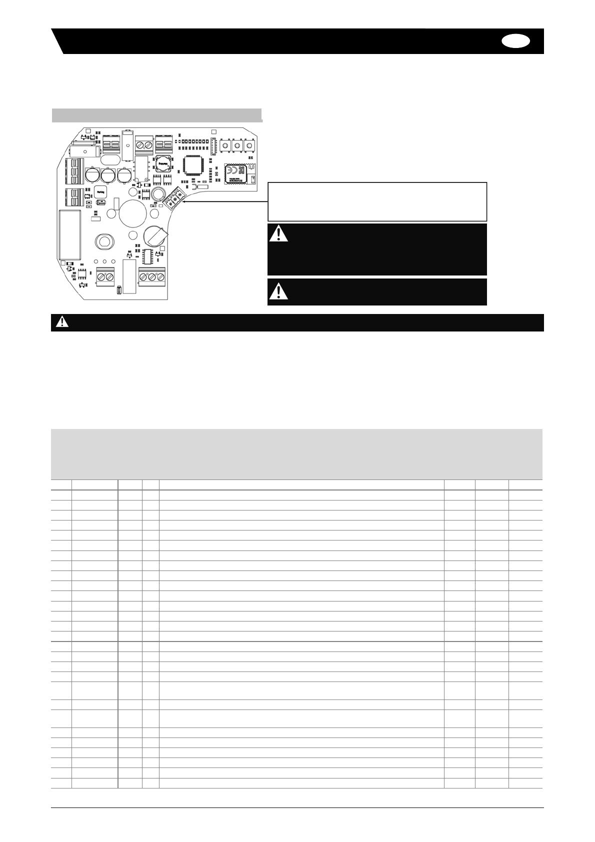
Conexiones eléctricas
Conectar el cable de comunicación MODBUS al conector RS485 (
0-A-B
) de la tarjeta GPS
Conectar el cable de alimentación eléctrica a las terminales 1 y 3 del conector de alimentación (Ca) de la tarjeta de
alimentación (ver p.28) :
1 : neutro (50/60 Hz) o negativo (DC)
3 : fase (50/60 Hz) o positivo (DC)
Registro
Función
R/W
Bytes
Descripción
valor mín.
valor por
defecto
valor máx.
1 0x03 R 2 Versión software 0 0 65535
9 0x03 / 0x10 R/W 2 Dirección del actuador 1 247 247
12 0x03 R 2 rampa de arranque (unidad : 0,1 s) 0 5 20
21 0x03 R 2 retrasos en la detección de la sobrecarga (unidad : 0,1 s) 0 10 20
22 0x03 R 2 Limitador de par (%) 10 100
27 0x03 R 2 Desbloqueo después de sobrecarga (unidad : 0,1 s) 0 10 20
30 0x03 R 2 Temperatura de seguridad (°C) 40 70 150
34 0x03 R 2 Temperatura mínima registrada -20 127
35 0x03 R 2 Temperatura máxima registrada 0 150
36 0x03 R 2 Temperatura actual (unidad : 0,1 °C) -200 1270
42 0x03 / 0x10 R/W 2 BBPR posición por defecto (“abierto”= 1 ; “inactivo”= 4 ; “cerrado”= 2) 1 2 4
50 0x03 / 0x10 R/W 2 Tipo de señal de pilotaje (“0_10 V”= 1 ; “4_20 mA”= 2) 1 2 2
51 0x03 / 0x10 R/W 2 Inversión de la señal de pilotaje (“normal”= 1 ; “Inverso”= 2) 1 1 2
60 0x03 / 0x10 R/W 2 Tipo de señal de recopia (“0_10V”= 1 ; “4_20 mA”= 2) 1 2 2
61 0x03 / 0x10 R/W 2 Inversión de la señal de recopia (“normal”= 1 ; “Inverso”= 2) 1 1 2
62 0x06 W 2 Señal de pilotaje (unidad : 0,1 %) (Modo manual solamente) 0 1000
63 0x03 R 2 Recopia (unidad : 0,1%) 0 1000
90 0x03 R 2 Estatus del sistema BBPR (“no disponible”= 0 ; “disponible”=1) 0 1 1
91 0x03 R 2 Nivel de carga de la batería (“HS”= 1 ; “se carga”= 2 ; “3 et 4”= cargada) 1 4
92 0x03 R 2 Contacto de informe de defecto (“no activado”= 0 ; “activado”=1) 0 0 1
100 0x03 / 0x06 R/W 2 Modo actual (“manual”= 0x01 ; “POSI”= 0x02 ; “Prog.”= 0x04 ;
“aprendizaje”= 0x16 ; “BBPR”= 0x64) 1 2 64
102 0x03 R 2 Posición (“apertura”= 7 ; “cierre”= 8 ; “stop”= 4 ; “sobrecarga”= 10) 4 10
103 0x03 R 2 Posición (“abierto”= 0x01 ; “apertura”= 0x17 ; “cerrado”= 0x02 ;
“cierre”= 0x18 ; “stop”= 0x04 ; “sobrecarga”= 0x16) 1 18
120 0x03 R 2 Número de ciclos 0 0 65535
122 0x03 R 2 Número de defectos 0 0 65535
123 0x03 R 2 Número de cortes de suministro eléctrico 0 0 65535
124 0x03 R 2 Tiempo de funcionamiento (horas) 0 65535
125 0x03 R 2 Tiempo de funcionamiento (minutas) 0 59
126 0x03 R 2 Tiempo de funcionamiento (segundas) 0 59
Conector RS485 (serie) para comunicación MODBUS-RTU
Para el último actuador de la línea (ver diagrama
p.27), es necesario conectar una resistencia de
terminación 120 Ω (suministrada) entre los
terminales A y B.
Para que el actuador pueda ser pilotado, debe
estar en modo "manual" (por defecto).
Para más información, consulte los manuales de los actuadores.
Tabla de registros


