La página se está cargando...

CORNER SINK BASE CABINET |
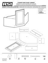
GABINETE DE BASE DE FREGADERO ESQUINADO
ASSEMBLY & INSTALLATION INSTRUCTIONS |
INSTRUCCIONES DE ENSAMBLAJE E INSTALACIÓN
Based on production dates, hardware and assembly methods are dierent.
2x
1x
S2*
6x
WD*
2x
90 DEGREE
BRACKET 1x
BR
2x
(SBP)
(DBP)
(LSP) BP
(SBP)
(TK)
(FC)
(RBP)
(DBP)
(BP)
(S2)
(DBP)
(S2)
(S2)
(S2)
° BR
2x
1x
S2*
6x
WD*
2x
90 DEGREE
BRACKET 1x
BR
2x
(SBP)
(DBP)
(LSP) BP
(SBP)
(TK)
(FC)
(RBP)
(DBP)
(BP)
(S2)
(DBP)
(S2)
(S2)
(S2)
° BR
• • • • • • • • • • • • • • • • • • • • • • • • •
Production dates June 2023 and later
will have two metal brackets.
Check packaging for production date
and green stripe. See pages: 5-8 then
skip to page 9.
• • • • • • • • • • • • • • • • • • • • • • • • •
Production dates prior to June 2023
will have cams and plastic angle brackets.
Check packaging for production date.
See pages: 2-4 then skip to page 9.
KC BR

CORNER SINK BASE CABINET |
GABINETE DE BASE DE FREGADERO ESQUINADO
2Install the diagonal back panel (DBP) to the
bottom panel (BP).
Instala el panel trasero diagonal (DBP) en el panel
inferior (BP).
ASSEMBLY & INSTALLATION INSTRUCTIONS |
INSTRUCCIONES DE ENSAMBLAJE E INSTALACIÓN
1Install plastic brackets (BR) on diagonal
back panel (DBP). Brackets are not pre-
drilled. Install screws directly through the bracket
into the panel.
Instala los soportes plásticos (BR) en el panel trasero
diagonal (DBP). Los soportes no están pretaladrados.
Instala los tornillos directamente en el panel, a través
del soporte.
BR
x
S*
x
DBP
2x
*ACTUAL SIZE
*TAMAÑO REAL
S*
x
BR
x
KC
x S*
x
WD*
x
S*
x

4Install the plastic braces to the side panels.
Instala los soportes plásticos en los paneles laterales.
BR
x S*
x
LSP RSP
3Install the two shorter side panels (SBP) to
the bottom panel.
Instala los dos paneles laterales más cortos (SBP) en
el panel inferior.
S
S SBP
BP
DBP
S
SBP S
4x
WD
S
x
WD*
x
WD*
x S
x
5Install the larger side panels (LSP) and (RSP)
onto the bottom panel.
Instala los dos paneles laterales más grandes (LSP) y
(RSP) en el panel inferior.
4x
WD
S
S
S
S
S
S
S
S
BP
SBP SBP
DBP
LSP RSP
6Lay the cabinet on its back. Install the
toe-kick plate (TK) to the side panels with
brackets. Secure the diagonal back panel (DBP) to
the side panels (SBP). Press the cams (KC2) into
the bottom panel (BP).
Acuesta el gabinete sobre su parte trasera. Instala la
placa del zócalo (TK) en los paneles laterales con los
soportes. Asegura el panel trasero diagonal (DBP) a los
paneles laterales (SBP). Presiona las levas (KC2) en el
panel inferior (BP).
S*
x KC
x
S
S S
S
TK
SBP
DPB
BP
KC
KC
7Install face frame (FC) onto bottom panel and
tighten cams (KC2).
Instala el marco frontal (FC) en el panel inferior y
aprieta las levas (KC2)
TK
DBP
SBP BP

8Carefully set the cabinet upright and secure the face frame (FC) with the brackets (BR).
Coloca el gabinete cuidadosamente en posición vertical y asegura el marco frontal (FC) con los soportes (BR).
S
S
S*
x

(SBP)
(LSP)
(BP)
(SBP)
(FC)
(RBP)
(DBP)
(TK)
RAW SIDE
LADO SIN ACABADO
CORNER SINK BASE CABINET |
GABINETE DE BASE DE FREGADERO ESQUINADO
Instala los soportes metal 135° (BR) en el panel trasero diagonal (DBP). Los soportes están pretaladrados.
Instala los tornillos directamente en el panel, a través del soporte.
Install two metal 135° brackets (BR) on diagonal back panel (DBP) in pilot holes.
135° BR
2x
S2*
4x
Careful not to overtorque screws
(DBP)
2x
(S2)
(S2)
Careful not to overtorque screws
Ten cuidado de no apretar
demasiado los tornillos
2x
1x
S2*
6x
WD*
2x
90 DEGREE
BRACKET 1x
BR
2x
(SBP)
(DBP)
(LSP) BP
(SBP)
(TK)
(FC)
(RBP)
(DBP)
(BP)
(S2)
(DBP)
(S2)
(S2)
(S2)
2x
1x
S2*
6x
WD*
2x
90 DEGREE
BRACKET 1x
BR
2x
(SBP)
(DBP)
(LSP) BP
(SBP)
(TK)
(FC)
(RBP)
(DBP)
(BP)
(S2)
(DBP)
(S2)
(S2)
(S2)
° BR
x S
x
2x
1x
S2*
6x
WD*
2x
90 DEGREE
BRACKET 1x
BR
2x
(SBP)
(DBP)
(LSP) BP
(SBP)
(TK)
(FC)
(RBP)
(DBP)
(BP)
(S2)
(DBP)
(S2)
(S2)
(S2)
2x
1x
S2*
6x
WD*
2x
90 DEGREE
BRACKET 1x
BR
2x
(SBP)
(DBP)
(LSP) BP
(SBP)
(TK)
(FC)
(RBP)
(DBP)
(BP)
(S2)
(DBP)
(S2)
(S2)
(S2)
S
x S
x
WD
x
° BR
x
° BR
x
(SBP)
(LSP)
(BP)
(SBP)
(FC)
(RBP)
(DBP)
(TK)
RAW SIDE
LADO SIN ACABADO
1Install two metal 135° brackets (BR) on diagonal back panel (DBP) in pilot holes. | Instala dos
soportes metálicos de 135° (BR) en el panel posterior diagonal (DBP) utilizando cuatro tornillos S2 en los
orificios guía
ASSEMBLY & INSTALLATION INSTRUCTIONS |
INSTRUCCIONES DE ENSAMBLAJE E INSTALACIÓN
Requires 2 people to assemble. Carefully hold and support entire unit when moving.
El ensamblaje requiere de 2 personas. Sostén y apoya con cuidado toda la unidad cuando la muevas.

(S2)
(SBP)
(DBP)
(BP)
4x
(WD)
(S2)
(S2) (S2)
(LSP) (RSP)
(S2)
(S2)
1x
135° BR
4x
90° BR
2x
S2*
12x
(S2)
2x
RAW SIDE
FINISHED SIDE
(BP)
(S2) (DBP) (S2) (S2)
(SBP)
(SBP)
(SBP)
WD*
2x
S2*
4x
(DBP)
(BP)
(S2)
FINISHED SIDE
RAW SIDE
(WD)
(BP) (S2)
2x
1x
FINISHED SIDE
LADO CON ACABADO
LADO CON ACABADO
LADO CON ACABADO
90° BR
1x
LADO SIN ACABADO
LADO SIN ACABADO
LADO SIN ACABADO
RAW SIDE
(S2)
(SBP)
(DBP)
(BP)
4x
(WD)
(S2)
(S2) (S2)
(LSP) (RSP)
(S2)
(S2)
1x
135° BR
4x
90° BR
2x
S2*
12x
(S2)
2x
RAW SIDE
FINISHED SIDE
(BP)
(S2) (DBP) (S2) (S2)
(SBP)
(SBP)
(SBP)
WD*
2x
S2*
4x
(DBP)
(BP)
(S2)
FINISHED SIDE
RAW SIDE
(WD)
(BP) (S2)
2x
1x
FINISHED SIDE
LADO CON ACABADO
LADO CON ACABADO
LADO CON ACABADO
90° BR
1x
LADO SIN ACABADO
LADO SIN ACABADO
LADO SIN ACABADO
RAW SIDE
2x
1x
S2*
6x
WD*
2x
90 DEGREE
BRACKET 1x
BR
2x
(SBP)
(DBP)
(LSP) BP
(SBP)
(TK)
(FC)
(RBP)
(DBP)
(BP)
(S2)
(DBP)
(S2)
(S2)
(S2)
S
x
2x
1x
S2*
6x
WD*
2x
90 DEGREE
BRACKET 1x
BR
2x
(SBP)
(DBP)
(LSP) BP
(SBP)
(TK)
(FC)
(RBP)
(DBP)
(BP)
(S2)
(DBP)
(S2)
(S2)
(S2)
WD
x
2x
1x
S2*
6x
WD*
2x
90 DEGREE
BRACKET 1x
BR
2x
(SBP)
(DBP)
(LSP) BP
(SBP)
(TK)
(FC)
(RBP)
(DBP)
(BP)
(S2)
(DBP)
(S2)
(S2)
(S2)
° BR
x
3Install 90° bracket (BR) to shorter side panels (SBP) and insert 2 wooden dowels into each SBP
panel, then flip unit to Install the two shorter side panels (SBP) to the bottom panel (BP) using
four S2 screws, and screw shorter side panels (SBP) to diagonal back panel (DBP). | Instala el soporte
de 90° (BR) en los paneles laterales más cortos (SBP) e inserta 2 clavijas de madera en cada panel SBP; luego,
voltea la unidad para instalar los dos paneles laterales más cortos (SBP) en el panel inferior (BP) utilizando
cuatro tornillos S2 y atornilla los paneles laterales más cortos (SBP) al panel posterior diagonal (DBP).
(S2)
(SBP)
(DBP)
(BP)
4x
(WD)
(S2)
(S2) (S2)
(LSP) (RSP)
(S2)
(S2)
1x
135° BR
4x
90° BR
2x
S2*
12x
(S2)
2x
RAW SIDE
FINISHED SIDE
(BP)
(S2) (DBP) (S2) (S2)
(SBP)
(SBP)
(SBP)
WD*
2x
S2*
4x
(DBP)
(BP)
(S2)
FINISHED SIDE
RAW SIDE
(WD)
(BP) (S2)
2x
1x
FINISHED SIDE
LADO CON ACABADO
LADO CON ACABADO
LADO CON ACABADO
90° BR
1x
LADO SIN ACABADO
LADO SIN ACABADO
LADO SIN ACABADO
RAW SIDE
2x
1x
S2*
6x
WD*
2x
90 DEGREE
BRACKET 1x
BR
2x
(SBP)
(DBP)
(LSP) BP
(SBP)
(TK)
(FC)
(RBP)
(DBP)
(BP)
(S2)
(DBP)
(S2)
(S2)
(S2)
S2
4x
2x
1x
S2*
6x
WD*
2x
90 DEGREE
BRACKET 1x
BR
2x
(SBP)
(DBP)
(LSP) BP
(SBP)
(TK)
(FC)
(RBP)
(DBP)
(BP)
(S2)
(DBP)
(S2)
(S2)
(S2)
WD
2x
(S2)
(SBP)
(DBP)
(BP)
4x
(WD)
(S2)
(S2) (S2)
(LSP) (RSP)
(S2)
(S2)
1x
135° BR
4x
90° BR
2x
S2*
12x
(S2)
2x
RAW SIDE
FINISHED SIDE
(BP)
(S2) (DBP) (S2) (S2)
(SBP)
(SBP)
(SBP)
WD*
2x
S2*
4x
(DBP)
(BP)
(S2)
FINISHED SIDE
RAW SIDE
(WD)
(BP) (S2)
2x
1x
FINISHED SIDE
LADO CON ACABADO
LADO CON ACABADO
LADO CON ACABADO
90° BR
1x
LADO SIN ACABADO
LADO SIN ACABADO
LADO SIN ACABADO
RAW SIDE
(S2)
(SBP)
(DBP)
(BP)
4x
(WD)
(S2)
(S2) (S2)
(LSP) (RSP)
(S2)
(S2)
1x
135° BR
4x
90° BR
2x
S2*
12x
(S2)
2x
RAW SIDE
FINISHED SIDE
(BP)
(S2) (DBP) (S2) (S2)
(SBP)
(SBP)
(SBP)
WD*
2x
S2*
4x
(DBP)
(BP)
(S2)
FINISHED SIDE
RAW SIDE
(WD)
(BP) (S2)
2x
1x
FINISHED SIDE
LADO CON ACABADO
LADO CON ACABADO
LADO CON ACABADO
90° BR
1x
LADO SIN ACABADO
LADO SIN ACABADO
LADO SIN ACABADO
RAW SIDE
2Install one 90° BR metal bracket in the rear center of the bottom panel (BP) using two S2 screws
through bracket into pilot holes. Install 2 wooden dowels into bottom panel (BP),Install the
diagonal back panel (DBP) to the bottom panel (BP) using two S2 screws. Be sure to push BP into
groove on DBP. | Instala un soporte metálico BR de 90° en el centro de la parte posterior del panel inferior
(BP) utilizando dos tornillos S2 a través del soporte en los orificios guía. Instala 2 clavijas de madera en el panel
inferior (BP). Instala el panel posterior diagonal (DBP) en el panel inferior (BP) utilizando dos tornillos S2.
Asegúrate de empujar el BP en la ranura en DBP.
4Install two metal 135° brackets (BR) into each side panel using pre-drilled holes and four S2
screws. Install two 90° brackets (BR), one in the center of each panel using two S2 screws. |
Instala dos soportes metálicos de 135° (BR) en cada panel lateral utilizando orificios pretaladrados y cuatro
tornillos S2. Instala dos soportes de 90° (BR), uno en el centro de cada panel usando dos tornillos S2.
2x
1x
S2*
6x
WD*
2x
90 DEGREE
BRACKET 1x
BR
2x
(SBP)
(DBP)
(LSP) BP
(SBP)
(TK)
(FC)
(RBP)
(DBP)
(BP)
(S2)
(DBP)
(S2)
(S2)
(S2)
S
x
2x
1x
S2*
6x
WD*
2x
90 DEGREE
BRACKET 1x
BR
2x
(SBP)
(DBP)
(LSP) BP
(SBP)
(TK)
(FC)
(RBP)
(DBP)
(BP)
(S2)
(DBP)
(S2)
(S2)
(S2)
° BR
x
2x
1x
S2*
6x
WD*
2x
90 DEGREE
BRACKET 1x
BR
2x
(SBP)
(DBP)
(LSP) BP
(SBP)
(TK)
(FC)
(RBP)
(DBP)
(BP)
(S2)
(DBP)
(S2)
(S2)
(S2)
° BR
x
(S2)
(SBP)
(DBP)
(BP)
4x
(WD)
(S2)
(S2) (S2)
(LSP) (RSP)
(S2)
(S2)
1x
135° BR
4x
90° BR
2x
S2*
12x
(S2)
2x
RAW SIDE
FINISHED SIDE
(BP)
(S2) (DBP) (S2) (S2)
(SBP)
(SBP)
(SBP)
WD*
2x
S2*
4x
(DBP)
(BP)
(S2)
FINISHED SIDE
RAW SIDE
(WD)
(BP) (S2)
2x
1x
FINISHED SIDE
LADO CON ACABADO
LADO CON ACABADO
LADO CON ACABADO
90° BR
1x
LADO SIN ACABADO
LADO SIN ACABADO
LADO SIN ACABADO
RAW SIDE

2x
1x
S2*
6x
WD*
2x
90 DEGREE
BRACKET 1x
BR
2x
(SBP)
(DBP)
(LSP) BP
(SBP)
(TK)
(FC)
(RBP)
(DBP)
(BP)
(S2)
(DBP)
(S2)
(S2)
(S2)
WD
x
2x
1x
S2*
6x
WD*
2x
90 DEGREE
BRACKET 1x
BR
2x
(SBP)
(DBP)
(LSP) BP
(SBP)
(TK)
(FC)
(RBP)
(DBP)
(BP)
(S2)
(DBP)
(S2)
(S2)
(S2)
S
x
2x
1x
S2*
6x
WD*
2x
90 DEGREE
BRACKET 1x
BR
2x
(SBP)
(DBP)
(LSP) BP
(SBP)
(TK)
(FC)
(RBP)
(DBP)
(BP)
(S2)
(DBP)
(S2)
(S2)
(S2)
S
x
5Install 4 wood dowels into the shorter side panels (SBP). Install the larger side panels (LSP) and
(RSP) onto the bottom panel (BP) using four S7 screws. Flip unit to install four S2 screws. Hold
panel down while screwing into pre-drilled holes to assure alignment. | Instala 4 clavijas de madera en
los paneles laterales más cortos (SBP). Instala los dos paneles laterales más grandes (LSP) y (RSP) en el panel
inferior (BP) utilizando cuatro tornillos S7. Voltea la unidad para instalar cuatro tornillos S2. Sostén el panel hacia
abajo mientras lo atornillas en los orificios pretaladrados para asegurar la alineación.
WD*
S2*
4x
4x
S7
4x 4x
S2*
(DBP)
4x
(WD)
(S7)
(S7) (LSP) (RSP)
(S7)
(BP)
(S7)
(SBP)
(SBP)
2x
(S2) (S2)
RAW SIDE
(FC)
(SBP) (BP)
(DBP)
(S2)
(S2)
90° BR
1x
FINISHED SIDE
LADO CON ACABADO
LADO SIN ACABADO
WD*
S2*
4x
4x
S7
4x 4x
S2*
(DBP)
4x
(WD)
(S7)
(S7) (LSP) (RSP)
(S7)
(BP)
(S7)
(SBP)
(SBP)
2x
(S2) (S2)
RAW SIDE
(FC)
(SBP) (BP)
(DBP)
(S2)
(S2)
90° BR
1x
FINISHED SIDE
LADO CON ACABADO
LADO SIN ACABADO
6Determine if you want the door to swing left or right and position face frame (FC) accordingly.
Install 90° bracket (BR) onto bottom of face frame (FC) in the pre-drilled pilot holes using two S2
screws. Then install face frame (FC) onto bottom panel (BP) using two S2 screws. | Determina si deseas
que la puerta gire hacia la izquierda o hacia la derecha y coloca el marco frontal (FC) según corresponda. Instala
el soporte de 90° (BR) en la parte inferior del marco frontal (FC) en los orificios pilotos pretaladrados utilizando
dos tornillos S2. Luego, instala el marco frontal (FC) en el panel inferior (BP) utilizando dos tornillos S2.
2x
1x
S2*
6x
WD*
2x
90 DEGREE
BRACKET 1x
BR
2x
(SBP)
(DBP)
(LSP) BP
(SBP)
(TK)
(FC)
(RBP)
(DBP)
(BP)
(S2)
(DBP)
(S2)
(S2)
(S2)
S
x
2x
1x
S2*
6x
WD*
2x
90 DEGREE
BRACKET 1x
BR
2x
(SBP)
(DBP)
(LSP) BP
(SBP)
(TK)
(FC)
(RBP)
(DBP)
(BP)
(S2)
(DBP)
(S2)
(S2)
(S2)
° BR
x
S2*
4x
(FC)
(SBP) (BP)
(DBP)
(S2)
90° BR
1x
DOOR
BR
FACE FRAME
MARCO DE LA CARA
PUERTA
(S2)
2x
(FC)
2x
S2*
4x
(FC)
(SBP) (BP)
(DBP)
(S2)
90° BR
1x
DOOR
BR
FACE FRAME
MARCO DE LA CARA
PUERTA
(S2)
2x
(FC)
2x

(FC)
(S2)
(S2)
(FC)
S2*
4x
(S2)
(BP)
(S2)
S2*
4x
(TK)
(DPB)
(SBP)
7Carefully set the cabinet upright and secure the face frame (FC) with the brackets (BR) and four
S2 screws. | Con cuidado, coloca el gabinete en posición vertical y asegura el marco frontal (FC) con los
soportes (BR) y cuatro tornillos S2.
2x
1x
S2*
6x
WD*
2x
90 DEGREE
BRACKET 1x
BR
2x
(SBP)
(DBP)
(LSP) BP
(SBP)
(TK)
(FC)
(RBP)
(DBP)
(BP)
(S2)
(DBP)
(S2)
(S2)
(S2)
S
x
6
78
S2*
4x
S2*
4x
S2*
4x
(FC)
(SBP)
(BP)
(DBP)
(S2)
(S2)
(S2)
(TK)
(S2)
(SBP)
(S2)
(BP)
(DPB)
(FC)
(FC)
(S2)
8CAREFULLY lay the cabinet on its back. Install the toe-kick plate (TK) to the side panels with
brackets using four S2 screws. | CON CUIDADO coloca el gabinete sobre su parte posterior. Instala la
placa del zócalo (TK) en los paneles laterales con los soportes utilizando cuatro tornillos S2.
2x
1x
S2*
6x
WD*
2x
90 DEGREE
BRACKET 1x
BR
2x
(SBP)
(DBP)
(LSP) BP
(SBP)
(TK)
(FC)
(RBP)
(DBP)
(BP)
(S2)
(DBP)
(S2)
(S2)
(S2)
S
x

STEP : CABINET INSTALLATION |
Select hardware that is best suited
for your wall type*
INSTALACIÓN DEL GABINETE | Selecciona los
herrajes que mejor se adapten a tu tipo de pared*
ASTUDS: Secure to wall
with #10 x 3" screws at
stud location.
VIGAS: Fíjalas a la pared con
tornillos núm.10 x 3 plg (7.62
cm) en la ubicación de las
vigas.
BDRYWALL: Drill holes and secure to the wall
with toggle bolts. Note: Use toggle bolts only
when cabinet cannot be
attached to a wall stud.
Cabinet must also be at-
tached to adjacent cabinet
as outlined in Step 3.
DRYWALL: Taladra orificios y
asegura a la pared con pernos
acodados. Nota: Usa pernos
acodados sólo si el gabinete
no se puede fijar a la viga de pared. El gabinete tam-
bién debe asegurarse a otro gabinete adyacente,
como lo indica el Paso 3.
CCONCRETE: Drill ¼"
holes, insert #10 wall
anchors and secure to wall
with #10 x 3" screws.
CONCRETO: Taladra orificios
de 1/4 plg 0.63 cm, inserta an-
clajes de pared Núm. 10 y fija a
la pared con tornillos Núm. 10 x 3 plg (7.62 cm)
IMPORTANT: Use “pan head” or “round head”
screws with seat washers. Seat screws tightly
against back rail or panel without driving into
back rail or panel material.
IMPORTANTE : usa tornillos de “cabeza plana bise-
lada” o “cabeza redonda” con arandelas de asiento.
Coloca los tornillos firmemente contra el panel o el riel
trasero sin insertarlos en el panel o el riel.
STEP : COUNTERTOP CLEAT
INSTALLATION
Locate and mark all studlocations. Use 2x4
framing material as cleats to support the
countertop. Use a level to ensure the cleats are
level. Drill 3/16” pilot holes through the cleat and
into the stud. Mount the cleat to the wall with
hardware appropriate for your wall type.
INSTALACIÓN DEL LISTÓN DEL MOSTRADOR
Localiza y marca todas las ubicaciones de vigas.
Instala material de enmarcado 2x4 como listones para
sostener el mostrador. Usa un nivel para garantizar
que los listones estén nivelados. Perfora orificios
pilotos de 3/16 plg a través del listón y dentro de
la viga. Monta el listón en la pared con el herraje
correcto según el tipo de pared.
STEP : ATTACH CABINETS TOGETHER
Use C-clamps to align the adjacent cabinets to
the CornerSink Cabinet. Use a level to ensure the
cabinets are flush and level with each other. Drill
a 1/8” pilot hole in the faceframe above or below
each door hinge location. Attach the adjacent
cabinets to the corner cabinet using #8 x 2 1/2”
screws and countersink for best appearance.
ATTENTION: You must drill pilot holes to attach
cabinets together.
CONECTA LOS GABINETES ENTRE SÍ
Usa abrazaderas en C para alinear los gabinetes
adyacentes al Gabinete de Fregadero Esquinado.
Usa un nivel para garantizar que los gabinetes
queden a ras y a nivel entre sí. Taladra un orificio
piloto de 1/8 plg en el marco frontal arriba o
debajo del lugar donde irán las bisagras de
las puertas. Une los gabinetes adyacentes al
gabinete esquinado, usando tornillos núm. 8
x 2 1/2 plg e instala al ras para darle un mejor
aspecto. ATENCIÓN: Debes taladrar orificios
pilotos para unir los gabinetes.
A
B
C
STEP 3:
36" 36"

STEP : MOUNT CABINETS TO THE WALL
Shim cabinets square (flat) to the wall so there
are no gaps between the back of the adjacent
cabinets and wall in mounting area. Drill a 3/16”
pilot hole at the stud locations through the back
panel of the adjacent cabinets and into the studs.
Mount the cabinets to the wall with hardware
appropriate for your wall type. Once your corner
cabinets have been installed work outword to
install the remaining cabinets.
IMPORTANT: Shim cabinets square (flat) to the
wall so there are no gaps between the back of the
adjacent cabinets and wall in mounting area. Drill
a 3/16” pilot hole at the stud locations through
the back rail of the adjacent cabinets and into
the studs. Mount the cabinets to the wall with
hardware appropriate for your wall type. Once
your corner cabinets have been installed work
outword to install the remaining cabinets.
MONTA LOS GABINETES EN LA PARED: Coloca en
posición los tres gabinetes en la esquina. El gabinete
esquinero debería estar a 91.44 cm de la pared en
ambos lados. Usa un nivel para garantizar que los
gabinetes queden derechos y a nivel entre sí. Si es
necesario, usa cuñas para nivelar. IMPORTANTE:
Calza los gabinetes en escuadra (plano) a la pared
para que no haya espacios entre la parte posterior
de los gabinetes adyacentes y la pared en el área
de montaje. Taladra un orificio piloto de 3/16 plg
en las ubicaciones de las vigas a través del panel
posterior de los gabinetes adyacentes y dentro de las
vigas. Monta los gabinetes en la pared con el herraje
correcto según el tipo de pared. Después de instalar
los gabinetes esquineros, prosigue con los demás.
STEP : INSTALL REMAINING CABINETS
Drill a 3/16” pilot hole at the stud locations
through the back panel and into the stud. Make
sure to place screws 1” or more from the top,
bottom and sides. Level and mount the cabinet to
the wall with #10 x 3” screw. If needed, shim the
cabinet to level. DO NOT COMPLETELY TIGHTEN
MOUNTING SCREWS UNTIL ALL CABINETS
HAVE BEEN ATTACHED TOGETHER. After
all cabinets have been attached together and
are level and secure, then tighten all mounting
screws. Take care to seat mounting screws tightly
against back rail or panel without driving into
back rail or panel material. Check to be sure that
all cabinets remain level after tightening.
INSTALA LOS GABINETES RESTANTES
Taladra un orificio piloto de 3/16 plg en las ubicaciones
de las vigas a través del panel trasero y dentro de la
viga. Asegúrese de colocar los tornillos a 2.54 cm o
más de la parte superior, inferior y laterales. Nivela y
monta el gabinete a la pared con el tornillo Núm. 10 x 3
plg. Si es necesario usa cuñas para nivelar el gabinete.
NO APRIETES POR COMPLETO LOS TORNILLOS
DE MONTAJE HASTA QUE LOS GABINETES ESTÉN
UNIDOS. Aprieta todos los tornillos de montaje
después que todos los gabinetes hayan sido unidos
firmemente y estén a nivel. Asegúrate de que los
tornillos de montaje descansen firmemente contra el
riel posterior o el panel sin que perforen el material de
estos. Verifica que todos los gabinetes queden a nivel
después de apretados los tornillos.
We have partnered with BILT™ to provide
3D interactive instructions for this product.
Download the free BILT™ app to a mobile
device and search “Woodmark”
Nos hemos asociado con BILT para proporcionar
instrucciones interactivas en 3D para este
producto. Descargue la aplicación gratuita BILT
en un dispositivo móvil y busque “Woodmark”

Important health notice: Some of the building materials used in
this home (or these building materials) emit formaldehyde. Eye,
nose, and throat irritation, headache, nausea and a variety of asthma-
like symptoms, including shortness of breath, have been reported as a
result of formaldehyde exposure. Elderly persons and young children, as
well as anyone with a history of asthma, allergies, or lung problems, may
be at greater risk. Research is continuing on the possible long-term
eects of exposure to formaldehyde. Reduced ventilation may allow
formaldehyde and other contaminants to accumulate in the indoor air.
High indoor temperatures and humidity raise formaldehyde levels. When
a home is to be located in areas subject to extreme summer
temperatures, an air-conditioning system can be used to control indoor
temperature levels. Other means of controlled mechanical ventilation
can be used to reduce levels of formaldehyde and other indoor air
contaminants. If you have any questions regarding the health eects of
formaldehyde, consult your doctor or local health department.
WARNING: This product can expose you to chemicals including
formaldehyde which is known to the State of California to cause cancer,
and methanol, which is known to the State of California to cause birth
defects or other reproductive harm. For more information go to www.
P65Warnings.ca.gov
AVISO IMPORTANTE PARA LA SALUD: Algunos materiales de construcción usados en esta
vivienda (o estos materiales de construcción) emiten formaldehído. La irritación en ojos, nariz
y garganta; los dolores de cabeza, náusea y otros síntomas parecidos al asma, como la falta de aire,
han sido identificados como consecuencias de la exposición al formaldehído. Los ancianos y los niños
pequeños, así como quienquiera con historial de asma, alergias o problemas pulmonares, pueden
correr mayor riesgo. Continúan las investigaciones sobre los posibles efectos a largo plazo por
exposición al formaldehído.
La poca ventilación pudiera causar acumulación del formaldehído u otros contaminantes del aire en
interiores. Las altas temperaturas y humedad en interiores incrementan los niveles de formaldehído.
Para viviendas en zonas de temperaturas extremas durante el verano puede usarse un sistema de aire
acondicionado a fin de controlar los niveles de temperatura en interiores. Otros medios de ventilación
mecánica controlada pueden usarse para reducir los niveles de formaldehído y otros contaminantes
del aire en interiores. En caso de pregunta o duda con respecto a los efectos del formaldehído en la
salud, consultar al médico o llamar al departamento de salud local.
ADVERTENCIA: Este producto puede exponerte a sustancias químicas incluyendo formaldehído,
que se considera en el estado de California como causante de cáncer, y metanol, que se considera
en el estado de California como causante enfermedades congénitas y otros daños al sistema repro-
ductor. Para más información, visite www.P65Warnings.ca.gov
*The fastening solutions described here are rec-
ommendations only, and are based on commonly
used installations. Each installer must evaluate
the specific characteristics of the particular wall
on which the cabinets are to be installed to en-
sure the proper fastening solution is used and the
product is fastened safely and securely. This may
require hardware or fastening methods which are
dierent from, or additional to, what is described
here. AWC DOES NOT WARRANT THE INSTAL-
LATION OF THIS PRODUCT.
*Las soluciones de sujeción aquí descritas son sólo
recomendaciones y se basan en las instalaciones más
comúnmente utilizadas. Cada instalador tiene que
evaluar las características específicas de la pared en
que se instalarán los gabinetes para garantizar que la
solución de sujeción sea apropiada y que el producto
quede sujeto segura y firmemente. Ello podría requerir
herrajes o métodos de sujeción diferentes o adicio-
nales a los descritos aquí. AWC NO GARANTIZA LA
INSTALACIÓN DE ESTE PRODUCTO.
Do you have a question about this product? Do you have damaged
or missing parts or need installation advice? DO NOT RETURN the
product to the store. We’re here to help.
¿Tiene alguna pregunta sobre este producto?¿Tiene piezas dañadas o
faltantes o necesitas algún consejo para la instalación? NO DEVUELVAS
el producto a la tienda. Estamos aquí para ayudarte.
Call us at/Llamenos al:
1-888-578-4009
Email us at/Envíanos un email a:
HOMEPRODUCTS_CC@WOODMARK.COM
from Mon-Fri EST/ de Lunes a Viernes Hora del
Este: 8AM-7PM EST
IMPORTANT
___________
IMPORTANTE
Reviews are important to us. If you are happy
with this product, please leave us a 5-star review.
Las reseñas son importantes para nosotros.
Si estás satisfecho con este producto, por favor,
déjanos una reseña de 5 estrellas.

EMAIL: HomeProducts_CC@woodmark.com TELEPHONE: U.S. Call (888) 578-4009 WEBSITE: www.AmericanWoodmark.com
AMERICAN WOODMARK
CORPORATION LIMITED WARRANTY
This warranty covers defects in materials and workmanship in your
American Woodmark Kitchen cabinets under normal home use. This
warranty is oered only to the original residential consumer purchaser
(“the Consumer”) and may not be transferred.
What This Warranty Covers: American Woodmark Corporation
(“AWC”), the manufacturer of this kitchen cabinetry, warrants its parts
and products to be free of defects in materials and workmanship from
the original date of purchase under normal home use. This warranty is
oered to the original residential consumer purchaser only and may not
be transferred.
How Long The Warranty Lasts: The coverage of this warranty lasts
for the lifetime of the original purchaser, so long as he or she owns the
home in which the product was first installed. Coverage for unfinished
kitchen cabinets lasts 1 year.
Warrantor: American Woodmark Corporation, 561 Shady Elm Road,
Winchester, VA 22602 (888) 578-4009
What American Woodmark Will Do Under The Warranty: During
the warranty period, AWC, at its option, will repair or replace any
part or product that proves to have substantial defects in materials
or workmanship, or AWC will provide an equivalent replacement
product, at no cost to the Consumer. AWC reserves the right to change
specifications in design and materials without notice and with no
obligation to retrofit products we previously manufactured.
Duties of the Consumer: If you purchased American Woodmark
cabinetry and need a replacement part or would like to file a warranty
claim, IMMEDIATELY NOTIFY AWC BY E-MAIL (Homeproducts_CC@
woodmark.com ) OR TELEPHONE (888-578-4009) OF THE ISSUE. You
must provide a copy of the original sales receipt from your purchase.
Hand Carving, Wood, Aging And Printing Limitations: Because of the
varying natural characteristics of wood and the eects of aging, product
shown in displays and/or printed materials will not be an exact match to
new cabinetry you will receive. Depending on the wood characteristics,
the age of a sample and the environment of the showroom, samples
will show some degree of variation from new product. In addition,
you should not expect all doors, drawer fronts, trim or molding to
match exactly in either finish or grain. Variation in wood is normal and
unavoidable. In addition, it is not possible to match our colors exactly in
printed materials. Therefore, you should view the actual samples when
making your color selection. Slight variation in size and design is also
characteristic of individually hand-carved items. This variation can occur
from carving to carving, which only adds to their uniqueness and beauty.
Limitations and Exclusions: This warranty does not cover defects or
damage which result from commercial use, improper transportation,
improper installation, use of unauthorized parts, mishandling, misuse,
abuse, neglect, abnormal use, improper maintenance, non-AWC repairs,
accidents, impact, or acts of God, such as hurricanes, fire, earthquakes
or floods, normal wear and tear, alterations, environmental conditions,
humidity absorption, or mold. This warranty, and any applicable implied
warranties, does not cover incidental or consequential damages arising
from any defects in the product, such as labor charges for installation
or removal of the product or any associated products. In addition,
variations in hand carved items, wood grain, finish color, aging or other
natural wood and stain characteristics are not considered defects and
are not covered by this warranty.
Disclaimers and Rights: AWC disclaims any implied warranty of
merchantability, and there are no express warranties other than those
set forth herein. ANY WARRANTY IMPLIED BY STATE LAW (WHETHER
OF MERCHANTABILITY OR FITNESS FOR A PARTICULAR USE OR
OTHERWISE) SHALL BE EFFECTIVE FOR ANY PRODUCT ONLY FOR
THE DURATION OF THE APPLICABLE LIMITED WARRANTY PERIOD
LISTED ABOVE. SOME STATES DO NOT ALLOW THE EXCLUSION OR
LIMITATION OF INCIDENTAL OR CONSEQUENTIAL DAMAGES, SO
THE ABOVE LIMITATION OR EXCLUSION MAY NOT APPLY TO YOU.
THIS WARRANTY GIVES YOU SPECIFIC LEGAL RIGHTS, AND YOU
MAY ALSO HAVE OTHER RIGHTS THAT VARY FROM STATE TO STATE.
How to Obtain Warranty Service: If you need replacement parts or
would like to make a warranty claim, please contact our Customer Care
Representative by mail, email, fax or telephone at the address or phone
numbers listed on this page. All warranty claims must include the model
number of the product, copy of the original receipt and the nature of the
problem. In addition, AWC may at its discretion require inspection of the
installation site or authorize the prepaid return of the claimed defective
part. Merchandise not preapproved for return will not be accepted and
the associated claim not accepted.
Products should be examined for defects prior to
installation. This warranty also does not cover labor charges
for installation or removal of the product or any associated
products. If upon inspection you find our product has a
damaged or missing part, it may not be necessary to return
the unit to the store of purchase. Please contact AWC
customer care to possibly obtain a replacement part.
GARANTÍA LIMITADA DE AMERICAN WOODMARK CORPORATION
Esta garantía cubre defectos en materiales y mano de obra en sus gabinetes de cocina Amer-
ican Woodmark bajo uso doméstico normal. Esta garantía se ofrece únicamente al comprador
consumidor residencial original (“el Consumidor”) y no puede transferirse.
Qué Cubre la Garantía: American Woodmark Corporation (“AWC”), el fabricante de estos
gabinetes de American Woodmark, garantiza que sus piezas y productos están libres de
defectos en materiales y mano de obra desde la fecha original de compra bajo uso doméstico
normal. Esta garantía se ofrece únicamente al comprador consumidor residencial original y no
puede transferirse.
Cuánto Dura la Garantía: La cobertura de esta garantía dura toda la vida del comprador
original, siempre que sea propietario de la vivienda en la que se instaló el producto por primera
vez. La cobertura para gabinetes de cocina sin acabado es de 1 año.
Garante: American Woodmark Corporation, 561 Shady Elm Road, Winchester, VA 22602
(888) 578-4009
Qué hará American Woodmark bajo la garantía: Durante el período de garantía, AWC, a
su opción, reparará o reemplazará cualquier pieza o producto que demuestre tener defectos
sustanciales en materiales o mano de obra, o AWC proporcionará un producto de reemplazo
equivalente, sin costo para el consumidor. AWC se reserva el derecho de cambiar las espe-
cificaciones de diseño y materiales sin previo aviso y sin ninguna obligación de renovar los
productos fabricados previamente.
Deberes del Consumidor: Si compró gabinetes de American Woodmark y necesita una
pieza de repuesto o desea presentar un reclamo de garantía, NOTIFIQUE INMEDIATAMENTE
A AWC POR CORREO ELECTRÓNICO (Homeproduc[email protected]) O POR TELÉ-
FONO (888-578-4009) DEL PROBLEMA. Debe proporcionar una copia del recibo de venta
original de su compra.
Limitaciones de talla a mano, madera, envejecimiento e impresión: Debido a las carac-
terísticas variables naturales de la madera y a los efectos del envejecimiento, el producto
mostrado en la exhibición y/o en los materiales impresos puede no coincidir exactamente con
los gabinetes nuevos que usted recibirá. Dependiendo de las características de la madera,
la edad de la muestra y las condiciones ambientales de la sala de exhibición, las muestras
variarán en cierto grado, del producto nuevo. Además, usted no deberá esperar que todas las
puertas, caras de los cajones, acabados o molduras tengan acabados o vetas idénticos. La
variación de la madera es normal e inevitable. Además, es imposible reproducir exactamente
nuestros colores en el material impreso. Por consiguiente, usted debe ver las muestras reales
al elegir su color. Una ligera variación en tamaño y diseño también es característica de los
artículos tallados a mano individualmente. Esta variación puede suceder en cada talla, lo que
solo le añade singularidad y belleza.
Limitaciones y Exclusiones: Esta garantía no cubre defectos o daños que resulten del uso
comercial, transporte inadecuado, instalación incorrecta, uso de piezas no autorizadas, mal
manejo, mal uso, abuso, negligencia, uso anormal, mantenimiento inadecuado, reparaciones
que no sean de AWC, accidentes, impactos o actos de Dios, como huracanes, incendios,
terremotos o inundaciones, desgaste normal, alteraciones, condiciones ambientales, absorción
de humedad o moho. Esta garantía y cualquier otra garantía implícita correspondiente, no
cubre daños incidentales o secundarios resultado de cualquier defecto en el producto, tales
como cargos por mano de obra por la instalación o retiro del producto o de cualquier producto
relacionado. Además, en los artículos tallados a mano, las variaciones en la veta de la madera,
el color del acabado, el envejecimiento u otras características de la madera o el tinte no se
considerarán defectos y no están cubiertos por esta garantía.
Exenciones de Responsabilidad y Derechos: AWC renuncia a cualquier garantía implícita
de comerciabilidad y no existen garantías expresas distintas de las aquí establecidas.
CUALQUIER GARANTÍA IMPLÍCITA POR LA LEY ESTATAL (YA SEA DE COMERCIABILIDAD
O APTITUD PARA UN USO PARTICULAR O DE OTRA MANERA) SERÁ EFECTIVA PARA
CUALQUIER PRODUCTO SOLAMENTE DURANTE LA DURACIÓN DEL PERÍODO DE GA-
RANTÍA LIMITADA APLICABLE INDICADO ARRIBA. ALGUNOS ESTADOS NO PERMITEN
LA EXCEPCIÓN O LIMITACIÓN DE DAÑOS DIRECTOS O INDIRECTOS, POR TANTO LA
EXCEPCIÓN O LIMITACIÓN ANTERIOR PUEDE NO SER APLICABLE EN SU CASO. ESTA
GARANTÍA LE OTORGA DERECHOS LEGALES ESPECÍFICOS Y ES POSIBLE QUE TAMBIÉN
GOCE DE OTROS DERECHOS QUE VARÍAN DE UN ESTADO A OTRO.
Cómo Recibir Servicio de Garantía: Si necesita piezas de reemplazo o le gustaría hacer una
reclamación de garantía, por favor, contacte a nuestro Representante de Atención al Cliente
por correo electrónico, fax o teléfono, por medio de la dirección o el número de teléfono provis-
tos en esta página. Todas las reclamaciones de garantía deben incluir el número de modelo del
producto, copia del recibo original y la naturaleza del problema. Además AWC podrá, a su dis-
creción, requerir una inspección del sitio de la instalación o autorizar la devolución prepagada
de la pieza defectuosa por la cual se hace la reclamación. No se aceptará ninguna mercancía
cuya devolución no haya sido previamente aprobada ni ninguna reclamación relacionada con
tal mercancía.
Antes de la instalación, los productos deben examinarse en busca de defectos. Esta
garantía tampoco cubre los cargos por mano de obra relacionados con la instalación
o retiro del producto o productos relacionados. Si al inspeccionar el producto ust-
ed encuentra que falta una pieza o que alguna de ellas está dañada, puede que no
sea necesario devolver la unidad a la tienda donde la compró. Por favor, contacte a
atención al cliente de AWC para determinar la posibilidad de obtener una pieza de
reemplazo.
/