Stern Green AB 1953 Touchless Deck Mounted Faucet Guía de instalación
- Tipo
- Guía de instalación

ELECTRONIC LAVATORY FAUCET
GRIFO ELECTRÓNICO PARA LAVABO
GREEN & GREEN 1000
INSTALLATION AND MAINTENANCE GUIDEINSTALLATION AND MAINTENANCE GUIDE
MANUAL DE INSTALACIÓN Y MANTENIMIENTOMANUAL DE INSTALACIÓN Y MANTENIMIENTO

1
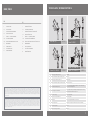
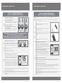
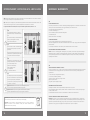
V battery Power supply for battery versions:EN
Pila de VFuente de alimentación para versiones a pilasES
V transformerPower supply for electricity versionsEN
Transformador de VFuente de alimentación para versiones eléctricasES
.. bar ( PSI). With water pressure of more than 8 bars,
use a pressure reducing valve
Recommended water pressureEN
,-, bar PSI. Con una presion de agua superior a 8 bar,
utilice una valvula reductora de presion
Presión de agua recomendadaES
mm. Adjustable.Preset sensor rangeEN
mm. Ajustable.Rango del sensor preestablecidoES
seconds. Adjustable with remote control.Security time:EN
segundos. Se puede modicar con el mando a distancia.Tiempo de seguridadES
Max. º CHot water temperatureEN
Máx. °CTemperatura del agua calienteES
Green AB Green B AB
Green B AB
Green E AB
Green E AB
Green AB
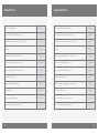
ES
INFORMACIÓN TÉCNICA
CONTENIDO DEL EMBALAJE
INFORMACIÓN PREVIA A LA INSTALACIÓN
INSTALACIÓN DEL GRIFO
GREEN TECHNICIAN’S MIXER
CONFIGURACIÓN DE PARÁMETROS
INSTRUCCIONES PARA LA SUSTITUCIÓN DE LA PILA
MANTENIMIENTO
LISTA DE REPUESTOS
SOLUCIÓN DE PROBLEMAS
GARANTÍA LIMITADA
EN
TECHNICAL DATA
PACK CONTENTS
PRE INSTALLATION INFORMATION
FAUCET INSTALLATION
GREEN TECHNICIAN’S MIXER
SETTINGS ADJUSTMENT
BATTERY REPLACEMENT INSTRUCTIONS
MAINTENANCE
SPARE PARTS LIST
TROUBLESHOOTING
LIMITED WARRANTY
INDEX / ÍNDICE TECHNICAL DATA / INFORMACIÓN TÉCNICA
(EN) The information in this document reflects products at the date of printing. Stern Engineering Ltd reserves the right, subject to all applicable laws, at any time, at its sole
discretion, and without notice, to discontinue or change the features, designs, materials and other specications of its products, and to either permanently or temporarily withdraw
any of the forgoing from the market. All information in this document is provided “as is” without warranty of any kind, either expressed or implied, including but not limited to any
implied warranties of merchantability, tness for a particular purpose, or non-infringement. Stern Engineering Ltd assumes no responsibility for errors or omissions in the information
presented in this document. In no event shall Stern Engineering Ltd be liable for any special, incidental, indirect or consequential damages of any kind, or any damages whatsoever
arising out of or in connection with the use or performance of this information. The tradenames, trademarks, logos and service marks presented in this document, including their
design, are the property of Stern Engineering Ltd or other third parties and you are not permitted to use them without the prior written consent of Stern Engineering Ltd or such third
party as may own them.
(ES) La información contenida en este documento refleja productos existentes en la fecha de impresión. Stern Engineering Ltd. se reserva el derecho, sujeto a la legislación vigente,
de discontinuar o modicar, en cualquier momento, a su sola discreción y sin previo aviso, las características, diseños, materiales y demás especicaciones de sus productos, así
como de retirar del mercado, de forma permanente o temporal, cualquiera de los productos aquí recogidos. Toda la información contenida en este documento se proporciona “tal
cual”, sin garantía de ninguna clase, expresa a implícita, lo que incluye, aunque no se limita a, garantía de comercialización e idoneidad para un n particular o no incumplimiento
de los derechos de propiedad intelectual. Stern Engineering Ltd. no asume ninguna responsabilidad sobre los errores u omisiones que pudiera haber en la información presentada
en este documento. En ninguna circunstancia será Stern Engineering Ltd. responsable de daños especiales, fortuitos, indirectos o derivados de ninguna clase, ni de ningún daño
en absoluto derivado o relacionado con el uso o interpretación de la presente información. Los nombres comerciales, marcas registradas y logos presentados en este documento,
incluido su diseño, son propiedad de Stern Engineering Ltd. u otras terceras partes y su uso está prohibido sin el previo consentimiento escrito de su propietario, ya sea Stern
Engineering Ltd. o dichas terceras partes.

32
(EN) Familiarize yourself with the part names and conrm that the parts are included.
(ES) Familiarícese con los nombres de las piezas y verique que están todas incluidas.
(EN) Familiarize yourself with the part names and conrm that the parts are included.
(ES) Familiarícese con los nombres de las piezas y verique que están todas incluidas.
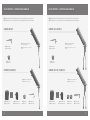
PACK CONTENTS / CONTENIDO DEL EMBALAJE PACK CONTENTS / CONTENIDO DEL EMBALAJE
GREEN AB1953
GREEN B/E AB1953
GREEN 1000 AB1953
GREEN 1000 B / E AB1953
OR OR
O O
EN X
Tap and attachments
with internal battery
ES X Grifo y accesorios, con pila
interna
EN X
Tap and attachments
with internal battery
ES X Grifo y accesorios, con pila
interna
EN X
Tap and attachments
ES X Grifo y accesorios
EN X
Tap and attachments
ES X Grifo y accesorios
EN X Filter
ES X Filtro
EN X Filter
ES X Filtro
EN X Filter
ES X Filtro
EN X Filters
ES X Filtros
EN x Allen Key
ES x Llave Allen
EN x Allen Key
ES x Llave Allen
EN x Allen Key
ES x Llave Allen
EN x Allen Key
ES x Llave Allen
EN V Battery box
ES Caja de pilas V
EN V Battery box
ES Caja de pilas V
EN V transformer
ES Transformador V
EN V transformer
ES Transformador V

54
INSTALLATION / INSTALACIÓN
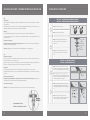
(EN) STEP 1 – PREPARATION FOR MOUNTING THE FAUCET
(ES) PASO 1 - PREPARACIÓN PARA EL MONTAJE DEL GRIFO
(EN) Shut o the water supply.
(EN) Cierre el suministro de agua.
(EN) Remove the hexagonal nut, disk, and
gasket. Do not remove the O-ring from the
escutcheon.
(ES) Retire la tuerca hexagonal, el disco y la
junta. No retire el anillo torico de la base del
grifo.
(EN) STEP 2 – INSTALLING THE FAUCET
(ES) PASO 2 - INSTALACIÓN DEL GRIFO
(EN) Place the faucet base into the hole in the
deck. Ensure that the O-ring is located between
the bottom of the faucet and the top of the deck.
O-RING
(ES) Coloque el grifo con el anillo tórico en el
oricio del lavabo o encimera. Asegúrese de que
el anillo tórico queda situado entre el lavabo o la
encimera y la parte inferior del grifo.
(EN) Slide the gasket and disk over the flexible
hose and secure the faucet in place by rmly
tightening the hexagonal nut onto the threaded
rod.
NUT /
TUERCA
DISC / DISCO
GASKET/
ARO TÓRICO
NUT /
TUERCA
DISC /
DISCO
GASKET/
ARO TÓRICO
O-RINGO-RING
(ES) Deslice la junta, el disco y la tuerca
hexagonal sobre el tubo flexible y je el grifo en
su sitio enroscando la tuerca con fuerza.
NUT /
TUERCA
DISC / DISCO
GASKET/
ARO TÓRICO
O-RING
(EN)
Check contents
Separate all parts from packaging and check each part with the pack contents section. Pay attention to the dierent
model variations.
Make sure all parts are accounted for before discarding any packaging material. If any parts are missing, do not
attempt to install this electronic faucet until you obtain the missing parts.
Warnings
Do not install the faucet facing a mirror or any other electronic system operated by an infrared sensor.
To prevent reflection problems, it is recommended to keep a minimum distance of cm between the faucet sensor
and the wash basin.
Preparation for Installation
Flush water supply lines thoroughly before installing the faucet. Do not allow dirt, Teflon tape or metal particles to
enter the faucet. Shut o water supply.
Important: All plumbing is to be installed in accordance with applicable codes and regulations.
(ES)
Vericación del contenido
Separe todas las piezas del embalaje y verique cada pieza con la sección “Contenido del embalaje”. Tenga en
cuenta las variaciones de los distintos modelos.
Asegúrese de que cuenta con todas las piezas antes de desechar cualquier material de embalaje. Si falta alguna de
las piezas, no intente instalar el grifo electrónico hasta que obtenga las piezas faltantes.
Advertencias
No instalar frente a un espejo ni frente a otro sistema electrónico que funcione con sensor de infrarrojos.
Para evitar problemas de reflejos, se recomienda mantener una distancia mínima de 30 cm entre el sensor del grifo
y el lavabo.
Preparación para la instalación
Asegúrese de purgar completamente con agua las tuberías de suministro antes de instalar el grifo. No permita que
se introduzcan en el grifo suciedad, cinta de teflón ni partículas metálicas.
Cierre el suministro de agua.
Importante: Toda la fontanería debe ser instalada de acuerdo con las normas y reglamentos vigentes.
PREINSTALLATION INFO / INFORMACIÓN PREVIA A LA INSTALACIÓN
Recommended hole size
Tamaño recomendado del oricio

76
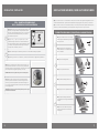
(EN) STEP 4 – CONNECTING THE POWER SOURCE
(ES) PASO 4 - CONEXIÓN DE LA FUENTE DE ALIMENTACIÓN
(EN) This product includes a self adjusting sensor. The ideal sensor range for the specic location will be set
automatically.
(EN) Este producto incluye un sensor autoadaptativo. Se establecerá de forma automática el rango ideal del
sensor para su ubicación concreta.
(EN) Important: Check that no objects are in front of the
sensor besides the washbasin.
(ES) Importante: Compruebe que no haya objetos delante
del sensor aparte del lavabo.
(EN) Now, remove the protecting sticker that covers the
sensor.
(ES) Retire la pegatina protectora que cubre el sensor.
(EN)
If your model is Green or Green :
Wait about seconds in order to allow the system to set
the ideal sensor range. Aer the self adjustment has taken
place the the solenoid valve will open and close for second
and a small amount of water will be leave the spout. Then the
product will be ready for use.
SECONDS/ SEGUNDOS
ABOUT/ APROX.
3O
(ES) Si su modelo es Green B o Green B:
Espere unos segundos para permitir al sistema
establecer el rango idóneo del sensor. Una vez completado
el autoajuste, la vállvula solenoide se abrirá durante un
segundo y se cerrará y saldrá una pequena cantidad de agua
por el caño. En ese momento el producto estará listo para
su uso.
(EN)
If your model is Green B or Green B:
Install the battery box on the wall underneath the sink using the two sided adhesive foam tape. The
cable connection must point down. (You can use an optional extension cable in order to assemble the
battery box up to . away from
the sink.)
(ES)
Si su modelo es Green B o Green 1000 B:
Instale la caja de pilas sobre la pared debajo del lavabo, utilizando la cinta adhesiva acolchada de dos
caras. La conexión del cable debe apuntar hacia abajo (puede utilizar la extensión de cable opcional
para instalar la caja de pilas a una distancia de hasta 3 metros (10 ) del lavabo).
(EN)
If your model is Green E or Green E:
Plug the transformer into the electricity socket and
connect the connectors.
(ES)
Si su modelo es Green E o Green E:
Enchufe el transformador en la toma de corriente y
conecte los conectores.
(EN) STEP 3 – CONNECTING THE WATER SUPPLY
(ES) PASO 3 - CONEXIÓN DEL SUMINISTRO DE AGUA
(EN) For Green / Green B/E AB
Connect the flexible pipe to the water supply.
For Green B/E AB versions
Connect the red flexible pipe to the hot water supply
and the blue flexible pipe to the cold water supply.
Para Green / Green B/E AB:
Conecte la tubería flexible a la entrada de agua.Para
Green B/E AB:
Conecte la tuberia flexible roja a la entrada de agua
caliente y el tubo flexible azul a la entrada de agua
fría.
(EN) MAKE SURE THAT THE FILTER(S) IS/ARE INSTALLED BETWEEN THE FLEXIBLE PIPE(S)
AND THE SHUT OFF VALVE(S) (ANGLE VALVE) (NOT SUPPLIED).
(ES) ASEGÚRESE DE QUE EL/LOS FILTRO(S) QUEDE(N) INSTALADO(S) ENTRE LA(S) TUBERÍA(S)
FLEXIBLE(S) Y LA(S) LLAVE(S) DE PASO (VÁLVULA(S) DE ÁNGULO) (NO SUMINISTRADAS)
(EN) Turn on the central water supply and the shut-o
valves (angle valves) and check for leaks.
(ES) Conecte el suministro central de agua y las llaves
de paso (valvulas de angulo) y verique que no haya
fugas.
3
(EN) Connect the power source.
(ES) Conecte la fuente de alimentación.
4
(EN) Once the power source is connected, wait
seconds to allow the system to set the ideal sensor
range. A red LED will flash continously to indicate this
adjustment period. The solenoid valve will open for
second to indicate that the ideal sensor range was set. 15
SECONDS/ SEGUNDOS
(ES) Una vez conectada la fuente de alimentación,
espere segundos para permitir al sistema establecer
el rango del sensor idóneo. La luz LED roja parpadeará
de forma continua para indicar que se está realizando
el ajuste. La válvula solenoide se abrirá durante un
segundo para indicar que el rango se ha establecido
5
(EN) If the automatically adjusted sensor range is not satisfactory to your purposes, please refer to the
section entitled “Settings adjustment”.
(ES) Si el rango establecido automáticamente no le satisface, consulte la sección “Conguración de
parámetros”.
INLET VERSION
INLETS VERSION
INSTALLATION / INSTALACIÓNINSTALLATION / INSTALACIÓN

98
STEP 4 – CONNECTING THE POWER SOURCE
PASO 4 - CONEXIÓN DE LA FUENTE DE ALIMENTACIÓN
(EN)
Wait about seconds in order to allow the system to set
the ideal sensor range. Aer the self adjustment has taken
place the solenoid valve will open and close for second and
a small amount of water will be leave the spout. Then the
product will be ready for use.
SECONDS/ SEGUNDOS
ABOUT/ APROX.
5
(ES)
Espere unos 5 segundos para permitir que el sistema
establezca el rango ideal del sensor. Una vez nalizado el
autoajuste, la válvula solenoide se abrirá durante un segundo
y se cerrará, y una pequeña cantidad de agua saldrá por el
caño. El producto estará listo para su uso.
(EN)
If the obtained range is unsatisfactory, refer to the section entitled “Settings adjustment”.
(ES)
Si el rango obtenido no es satisfactorio, consulte la sección titulada “Conguración de parámetros”.
(EN) NOTE: This model includes a special aerator that allows you to
adjust the water stream direction on site in order to prevent water
splashing if needed. To change the angle of the water stream, simply
move the adjustable tilting plate by pressing it smoothly.
ATTENTION! the aerator is tightened to prevent removal by hand.
(ES) NOTA: Este grifo incluye un aireador especial que permite
al usuario ajustar in situ la dirección del chorro de agua en caso
necesario, para evitar salpicaduras. Para modicar el ángulo del
chorro de agua, simplemente mueva la lámina basculante ajustable
con una ligera presion.
¡ATENCIÓN! El aireador está fuertemente apretado para evitar que se
pueda extraer manualmente.
TO REMOVE THE MIXING HANDLE / PARA RETIRAR LA PALANCA MEZCLADORA
(EN) Open the Allen screw at the the mixing
handle using the 2mm Allen key provided, and
remove the screw.
(ES) Suelte y retire el tornillo Allen de la
palanca mezcladora con la llave Allen de 2 mm
que se suministra.
(EN) Remove the mixing handle.
(ES) Retire la palanca mezcladora
(EN) Assemble the mixing handle cover.
(ES) Ponga la base de la palanza mezcladora.
(EN) Assemble the mixing handle Allen
screw and tighten it using the mm Allen key
provided.
(ES) Monte el tornillo Allen de la palanca
mezcladora y apriétela con la llave Allen
suministrada.
(EN) If your model is Green with technician’s mixer, this model allows removing the mixing handle in order to
allow the maintenance sta to adjust the water temperature without giving the same possibility to the end user.
(ES) Si su modelo es Green 1000 with technician’s mixer, este modelo permite retirar la palanca mezcladora para
permitir al personal de mantenimiento ajustar la temperatura del agua sin dar esta opción al usuario.
GREEN TECHNICIAN’S MIXER / GREEN TECHNICIAN’S MIXER
INSTALLATION / INSTALACIÓN

1110
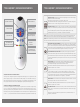
(EN) DETECTION RANGE: This faucet was supplied with a self adjusting sensor. The ideal detection range for
the specic location will be set automatically.
Only if necessary, use the remote control to adjust the sensor range as follows:
Press the RANGE button. Wait until a quick flashing of the LED in the sensor eye is perceived. Then, press + to
increase the range and – to reduce it. Every push will increase or decrease one level.
(ES) RANGO DE ALCANCE: Este grifo se suministró con un sensor autoadaptativo, que jará automáticamente
el rango del sensor más adecuado para cada ubicación concreta. Solo en caso necesario, utilice el mando a
distancia para ajustar el rango del sensor como sigue:
Pulse el botón RANGE, espere a que la luz LED del sensor parpadee rápidamente y pulse “+” para
incrementar el rango del sensor y “-“ para disminuirlo. Cada pulsación variará un nivel.
(EN) NOTE: Once you have changed the detection range with the remote control, the distance will be remembered by the
sensor, even if the power source is disconnected. To get back to the self adjustment mode, use the ADJ button only.
(ES) NOTA: Una vez modicado el rango de alcance con el mando a distancia, el sensor recordará la distancia incluso en caso
de desconexión de la fuente de alimentación. Para volver al modo de autoajuste, utilice el boton ADJ.
(EN ENTRANCE TO THE SELF ADJUSTMENT MODE: Check that no objects are in front of the sensor. Press the
ADJ button. Once a quick flashing of the LED of the sensor eye is perceived, remove your hand holding the
remote control and move away from the sensor area. The ideal sensor range for the specic location will be
set automatically. Once the self adjustment has taken place, the solenoid valve will be opened and closed
for second as an indication that the ideal sensor range was set and the product is ready for use.
(ES) ENTRADA AL MODO DE AJUSTE AUTOMÁTICO: Compruebe que no haya ningún objeto delante del
sensor. Pulse el boton ADJ. Cuando se perciba un rápido parpadeo de la LED del sensor, retire la mano que
sujeta el mando a distancia y aléjese de la zona del sensor. Se ajustará automáticamente el rango óptimo
para la ubicación concreta del producto. Una vez efectuado el ajuste, la válvula solenoide se abrirá durante
un segundo y se cerrará indicando que el rango óptimo del sensor se ha congurado y el producto está listo
para ser utilizado.
(EN SECURITY TIME: The Security time, prevents continuous running of water due to reflections or
vandalism. By default, if the sensor is covered for more than seconds the water flow will shut
automatically. To resume regular operation any obstruction must be removed.
Press the SEC button. Wait until a quick flashing of the LED in the sensor eye is perceived. Then, press + to
increase the security time and – to reduce it.
(ES) TIEMPO DE SEGURIDAD: El tiempo de seguridad evita la descarga continua de agua debida a reflejos
o a actos de vandalismo. Por defecto, si el sensor está tapado durante más de 90 segundos, el flujo
del agua cesará automáticamente. Para restablecer el normal funcionamiento, debe retirarse cualquier
causa de obstrucción. Pulse el boton “SEC”. Espere hasta que la LED del sensor parpadee rápidamente. A
continuación, pulse “+” para aumentar el tiempo de seguridad y “–” para disminuirlo.
EN DELAY IN TIME: It is recommended to change the delay in time for flush valves for urinals or toilets only.
If required, the delay in time can also be modied in faucets as follows:
Press the IN button. Wait until a quick flashing of the LED in the sensor eye is perceived. Then, press + to
increase the delay in time and – to reduce it.
(ES) TIEMPO DE REACCIÓN: Se recomienda cambiar el tiempo de reacción únicamente en fluxómetros para
urinario o para inodoro. En caso necesario, tambien puede modicarse el tiempo de reacción en los grifos de
la siguiente forma:
Pulse el boton IN y espere a que la LED del sensor parpadee. Pulse “+” para incrementar el tiempo de
respuesta y “-” para disminuirlo.
SETTINGS ADJUSTMENT / CONFIGURACIÓN DE PARÁMETROS SETTINGS ADJUSTMENT / CONFIGURACIÓN DE PARÁMETROS
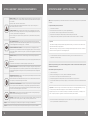
EN DETECTION RANGE
ES RANGO DE DETECCIÓN
EN DELAY IN TIME
ES TIEMPO DE REACCIÓN
EN SECURITY TIME
ES TIEMPO DE SEGURIDAD
EN COMFORT FLUSH
EN DESCARGA DE CONFORT
EN DELAY OUT TIME
ES TIEMPO DE RETRASO
EN TEMPORARY OFF FUNCTION
ES FUNCIÓN DE DESCONEXIÓN
TEMPORAL
EN RESET
ES REINICIO
EN SELF ADJUSTMENT MODE
ESENTRADA AL MODO DE
AJUSTE AUTOMÁTICO
EN HYGIENE FLUSH
ES DESCARGA HIGIÉNICA
EN ADJUSTING THE SETTINGS WITH THE REMOTE CONTROL
If necessary, the sensor settings can be adjusted as following: Shut o the water supply. In order to adjust the sensor with the
remote control, hold the remote control straight in front of the sensor in a distance of about 6-8” (cm). Choose the function
you want to adjust by pressing once on one of the function buttons. Aer pressing once on a specic function button, a quick
flashing of the LED at the front of the sensor will occur. At this stage, you can change the setting by pressing the (+) or the (-)
buttons, every push will increase or decrease one level. Aer nishing the adjustment, turn the water supply back on.
(ES) AJUSTE DE LA CONFIGURACIÓN CON EL MANDO A DISTANCIA
En caso necesario, la conguración del sensor puede ajustarse de la siguiente forma: Corte el suministro de agua. Para ajustar
el sensor con el mando a distancia, manténgalo justo delante del sensor a una distancia aproximada de a cm (6 a 8
pulgadas). Escoja la función que desea ajustar pulsando una vez uno de los botones de función. Después de pulsar una vez un
botón de función, la luz roja del sensor parpadeará rápidamente. En este momento puede cambiar la conguración presionando
los botones “+” o “-“; cada pulsación incrementará o disminuirá un nivel. Al nalizar el ajuste, restablezca el suministro de agua.

1312
EN DELAY OUT TIME: This button allows modifying the water flow time aer the user removes his hands from the
faucet. A delay out time close to 0 will save more water. An increased delay out time will make the user experience
more comfortable.
If required, the delay out time can be modied as follows:
Press the OUT button. Wait until a quick flashing of the LED in the sensor eye is perceived. Then, press + to
increase the delay out time and – to reduce it.
ES TIEMPO DE RETRASO: Este botón permite modicar el tiempo de flujo de agua después de que el usuario
retira las manos del sensor del grifo. Un tiempo de retraso mas largo resultará más agradable para el usuario. En
caso necesario, puede modicarse de la siguiente forma:
Pulse el botón OUT y espere a que la LED del sensor parpadee. Pulse “+” para incrementar el tiempo de retraso y
“-” para disminuirlo.
EN HOUR HYGIENE FLUSH: This model includes a hours hygiene flush which is disabled. To activate the
hygiene flush, press the clock button. Wait until a quick flashing of the LED in the sensor eye is perceived. Then press
+ to activate the hygiene flush. To disable it again, press – to deactivate it.
ES DESCARGA HIGIÉNICA A LAS HORAS: Este modelo incluye una función de descarga higiénica a las 24
horas del último uso, que está desactivada. Para activar la descarga higiénica, pulse el botón con un reloj. Espere
hasta ver un rápido parpadeo de la LED del sensor y pulse “+” para activar la descarga higiénica. Para desactivarla
de nuevo, pulse “-“.
EN COMFORT FLUSH: If your model includes a Comfort flush setting, it can be activated by pressing the flush
button.
When the button is pressed, one blink of the LED in the sensor eye is perceived. The pre-programmed flush cycle will
take place then.
The Comfort flush cannot be interrupted or deactivated by pressing any button until it is over.
ES DESCARGA DE CONFORT: Si su modelo incluye la función de descarga de confort, puede activarse presionando
el botón de descarga. Al pulsar el botón, la luz del sensor parpadea una vez. En ese momento tendrá lugar el ciclo de
descarga previamente programado. La descarga de confort no se puede interrumpir ni desactivar con ningún botón
una vez iniciada.
EN TEMPORARY OFF FUNCTION: This function is ideal to perform any kind of activity in front of the sensor without
operating the system (for example, cleaning).
The faucet will remain shut for minute when this button is pressed once. To cancel this function and to return to
normal operation press the On/O button again or wait minute.
ES FUNCIÓN DE DESCONEXIÓN TEMPORAL: Esta función es ideal para llevar a cabo cualquier actividad delante
del sensor sin poner el sistema en funcionamiento (por ejemplo, limpieza). El grifo quedará cerrado durante un
minuto cuando se pulse una vez este botón. Para cancelar esta función y volver al funcionamiento normal, pulse
de nuevo el botón de encendido y apagado o espere un minuto.
EN RESET BUTTON: This function restores all the factory settings except for the sensor range. If required, press
the Reset button and without releasing it, press the + button once.
ES REINICIO: Esta función permite al sensor volver a las especicaciones originales de fábrica, con excepción del
rango del sensor. En caso necesario, pulse el boton “RES” y, sin soltarlo, pulse una vez el botón “+”.
(EN) NOTE: To enter the self adjusting mode, use the ADJ button. To change the sensor range, use the RANGE button.
ES NOTA: Para entrar en el modo de autoajuste, utilice el boton ADJ. Para cambiar el rango del sensor, utilice el boton RANGE.
(EN) When the battery weakens, the LED indicator will blink at a constant rate. The battery must be replaced within
two weeks.
To replace the battery in Green, Green :
) Turn o the shut o valve.
Remove the faucet cover with the sensor, use the supplied Allen key.
3) Disconnect the connector coming from the electronic unit to the battery.
4) Replace the used battery with a new V battery. A Lithium battery is recommended.
) Carefully place the battery inside the body and reassemble the electronic unit connector to the battery.
(ES)Cuando la pila se esté agotando, el indicador LED parpadeará a un ritmo constante. Debe sustituirse la pila en
un máximo de dos semanas.
Para sustituir la pila en Green y Green :
Cierre la llave de paso.
) Retire la cubierta del grifo con el sensor, utilizando la llave Allen suministrada.
Desconecte el conector que va de la unidad electrónica a la pila.
) Sustituya la pila gastada con una pila nueva de V. Se recomienda el uso de pilas de litio.
Inserte cuidadosamente la pila en el cuerpo del grifo y conecte de nuevo el conector de la unidad electrónica a
la pila.
Important:
- Since water contacting the battery terminals rapidly drains the battery, do not allow moisture or water into the
system while the battery is being replaced.
- Make sure the O-ring is still in its groove and is not damaged. If needed replace it with a new one or clean and
lubricate it with silicon grease before reassembling the parts.
Importante: El contacto del agua con las terminales de la pila hace que se descargue rápidamente, por lo que
no debe permitir que entre humedad ni agua en el sistema durante la sustitución de la pila.
Asegúrese de que el aro tórico continúa en su ranura y no está dañado. En caso necesario, sustitúyalo por uno
nuevo o límpielo y lubríquelo con grasa de silicona antes de montar las partes de nuevo.
6) You must reassemble the faucet cover with the sensor within 30 seconds in order for the sensor self
adjustment to be done properly.
6) Debe montar de nuevo la cubierta del grifo con el sensor dentro de los segundos siguientes, para que
el sensor pueda realizar correctamente el autoajuste.
BATTERY REPLACEMENT / SUSTITUCIÓN DE LA PILA
SETTINGS ADJUSTMENT / CONFIGURACIÓN DE PARÁMETROS GREEN AB

1514
Important: Spent batteries should not be disposed of with normal household waste. Contact
your local authority for information on waste disposal and recycling.
1
(EN)
A. Disconnect the water proof connector
between the battery box and the electronic
unit.
B. Pull out the battery box from the battery box
holder by releasing the bottom clip.
C. Pull out the battery cover.
AB C
(ES)
A. Desconecte el conector resistente al agua
que hay entre la caja de pilas y la unidad
electrónica.
B. Tire para sacar la caja de pilas de su soporte
mientras libera la pestaña de la parte inferior.
C. Tire para sacar la cubierta de la pila.
2
(EN)
D. Replace the used battery with a new 9V
battery (Lithium battery is recommended).
E. Close the battery box and
slide it back on the battery
holder starting from the
bottom upwards.
F. Connect the connectors.
D E F
(ES)
D. Sustituya la pila usada con una pila nueva
de V (se recomienda el uso de pilas de litio).
E. Cierre la caja de pilas y deslícela para
colocarla en su soporte, de abajo hacia arriba.
F. Conecte los conectores.
3
(EN) IMPORTANT: Wait a few seconds before activating the product.
Close the battery compartment and ret the cover plate.
(ES) IMPORTANTE: Espere unos segundos antes de activar el producto.
Cierre el compartimento de la pila y coloque de nuevo la cubierta.
(EN) When the battery weakens, the LED indicator will blink at a constant rate when the user’s hands are within the
sensor range. The battery must be replaced within two weeks.
(ES) Cuando la pila se esté agotando, la luz indicadora parpadeará a una velocidad constante cuando las manos del
usuario estén en el rango del sensor. La pila debe reemplazarse en un plazo de dos semanas.
To replace the batteries in Green B, Green B / Para sustituir la pila en Green B, Green 1000 B:
EN
FILTER CLEANING INSTRUCTIONS
This faucet is provided with one / two stainless steel lter(s) preventing foreign particles to enter the lines. If the water flow has
decreased, this can be because the lter(s) is/are clogged. The lter(s) can be cleaned as follows:
. Shut-o the water shut o valve (angle valve).
. Disconnect the flexible pipe/s.
. Remove the lter(s) and wash it/them under running water.
. Reassemble the parts.
. Make sure that there is no water leakage.
SOLENOID VALVE SERVICING
The solenoid valve diaphragm requires periodical cleaning every six (6) month.
Remove the diaphragm from the solenoid valve and examine it for dirt. in case it is dirty or clogged, wash it under running water
and reassemble it.
Do not attempt to dismantle the solenoid valve if you are unfamiliar with electronic solenoid valves.
CARE AND CLEANING OF CHROME AND SPECIAL FINISHES
DO NOT use steel wool or cleansing agents containing alcohol, acid, abrasives, or the like. Use of any prohibited cleaning or
maintenance products or substances could damage the surface of the faucet. For surface cleaning of faucet use ONLY soap
and water, then wipe dry with clean cloth or towel. When cleaning bathroom tile, the faucets should be protected from any
splattering of harsh cleansers.
EN
INSTRUCCIONES PARA LA LIMPIEZA DE LOS FILTROS
Este grifo se suministra con uno o dos ltros de acero inoxidable que impiden la entrada de partículas externas en las tuberías.
Si ha disminuido el caudal de agua, puede deberse a que el ltro esta obstruido. El/los ltro(s) puede(n) limpiarse de la
siguiente forma:
1. Cierre la llave de paso del agua (válvula de angulo).
2. Desconecte el/las tubería(s) flexible(s).
3. Retire el/los ltro(s) y lávelo(s) bajo el agua corriente.
4. Monte las partes de nuevo.
5. Asegúrese de que no haya fugas de agua.
MANTENIMIENTO DE LA VÁLVULA SOLENOIDE
El diafragma de la válvula solenoide requiere una limpieza periódica cada seis (6) meses.
Retire el diafragma de la válvula solenoide y examínelo en busca de suciedad. Si está sucio u obstruido, lávelo bajo el agua
corriente y móntelo de nuevo.
No intente desarmar la válvula solenoide si no está familiarizado con válvulas solenoides electrónicas.
CUIDADOS Y LIMPIEZA DEL CROMADO Y ACABADOS ESPECIALES.
NO UTILICE lana de acero o productos de limpieza que contengan alcohol, ácido, ingredientes abrasivos o similares. El uso
de cualquier sustancia o producto prohibido para la limpieza o el mantenimiento puede dañar la supercie del grifo. Para la
limpieza de la supercie utilice SOLO agua y jabon, y aclare y seque con un pano o toalla limpia. Cuando se lleve a cabo la
limpieza de los azulejos, el grifo debe protegerse de las salpicaduras de los productos de limpieza.
MAINTENANCE / MANTENIMIENTO
BATTERY REPLACEMENT / SUSTITUCIÓN DE LA PILA
Importante: Las pilas usadas no deben desecharse junto con los residuos domésticos.
Póngase en contacto con las autoridades locales para obtener información sobre
eliminación de residuos y reciclaje.
GREEN AB

1716
-pack Solenoid Valve Kit
Seals and Screws Kit for Green/Green
Seals and Screws Kit for Green B/E/B/E
Cover Kit
pack Sensor Kit for Green/Green
pack Sensor Kit for Green B/Green B
-pack Sensor Kit for Green E / Green E
Battery box for V battery
pack V transformer (EU plug)
Mixing Handle kit
Remote Control B (Optional)
Soap & Water Remote Control (Optional)
Kit de válvula solenoide - Paquete de
Kit de juntas y tornillos para Green/Green
Kit de juntas y tornillos para Green B/E/B/E
Kit de tapa
Kit de sensor para Green/Green - Paquete de 10
Kit de sensor para Green B/Green B
Kit de sensor para Green E/Green E
Caja de pilas para pila de V
Transformador de V - Paquete de (enchufe EU)
Kit de palanca mezcladora
Mando a distancia botones (opcional)
Mando a distancia agua & jabón (opcional)
SPARE PARTS LIST LISTA DE REPUESTOS

1918
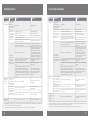
* “Security Mode”: If the sensor is covered for more than sec. the faucet will automatically shut off water flow.
To return to normal operation remove any blockage.
** In this case, the water flow will stop anyway after seconds because of the security time.
* “Modo de Seguridad”: Si el sensor esta cubierto durante más de segundos, el grifo cortará automáticamente el flujo de
agua. Para volver al funcionamiento normal, elimine cualquier obstrucción.
** En este caso, el flujo de agua cesará de todos modos tras 90 segundos, debido al tiempo de seguridad.
SOLUTIONCAUSE INDICATOR PROBLEM
Replace batteryLow battery.
. Sensor flashes
continuously
when user’s
hands are within
the sensor’s
range.
No water
coming out
of the faucet:
Increase the range. Range is too short.. LED in the
sensor does not
flash once when
user’s hands
are within the
sensor’s range.
Decrease the range. Range is too long.
The battery must be replaced. . Battery is completely used up
. Unit is in “Security Mode”*
Eliminate cause of reflection.
. Sensor is picking up reflections from the
washbasin or another object.
Connect the electronic unit
connectors to the solenoid.
. Connectors between the electronic unit and
solenoid are disconnected.
. LED in the
sensor flashes
once when
user’s hands
are within the
sensor’s range.
Unscrew solenoid, pull out the
plunger and the spring from
the solenoid and clean them.
Use scale remover material if
needed. When replacing the
plunger, please make sure that
the spring is in vertical position.
. Debris or scale in solenoid.
Clean the orice or replace
diaphragm.
. The central orice in the diaphragm is
plugged or the diaphragm is torn
Reduce the supply water
pressure.
. The water supply pressure is higher than
8 bar.
Shut o water supply and
unscrew one of the flexible
pipes in order to reduce the
pressure that blocks the
product.
. The water supply pressure is under 8 bars
and yet the pressure in the faucet’s body is
higher. This situation could be caused by a
sudden increase in the water supply pressure
that the back check prevents from dropping,
even aer water supply pressure drops under
8 bars.
Clean the orice or replace
diaphragm.
Debris or scale in diaphragm
. Sensor flashes
once when
user’s hands
are within the
sensor’s range.
Water flow
from spout
does not
stop:
Clean or eliminate case of
interference.
. Sensor is dirty or covered.**
. LED in the
sensor does not
flash once when
user’s hands
are within the
sensor’s range.
Decrease the range or eliminate
cause of reflection.
. Sensor is picking up reflections from the
washbasin or another object.
Remove, clean, re-installFilter or aerator is clogged
Water flow
diminished
SOLUCIÓNCAUSAINDICADORPROBLEMA
Sustituya la pilaPila agotada
. El sensor parpadea
contiuamente
cuando las manos
del usuario estan en el
rango del sensor
No sale agua
del grifo
Aumente el rango. El rango es demasiado corto . La LED del sensor
no parpadea una vez
cuando las manos
del usuario estan
situadas en el rango
del sensor.
Disminuya el rango.. El rango es demasiado largo.
La pila debe ser sustituida.. La pila está completamente agotada.
. La unidad está en “Modo de Seguridad”*.
Elimine el origen de los reflejos.
. El sensor está captando reflejos del lavabo o
de otro objeto.
Una los conectores de la unidad
electrónica a los de la válvula
solenoide.
. Los conectores de la unidad electrónica y la
solenoide están desconectados.
. La LED del
sensor parpadea
una vez cuando las
manos del usuario se
sitúan en el rango del
sensor.
Desatornille la solenoide, saque el
pistón y el resorte de la solenoide
y límpielos. Si es necesario,
utilice algun producto eliminador
de sarro. Al recolocar el pistón,
asegúrese de que el resorte queda
en posición vertical.
. Residuos o sarro en la solenoide.
Limpie el oricio o sustituya el
diafragma.
. El oricio central del diafragma está atascado o
el diafragma está roto.
Reduzca la presión del suministro
de agua.
. La presion del suministro de agua es superior
a 8 bar.
Corte el suministro de agua y
desenrosque una de las tuberías
flexibles para reducir la presión
que bloquea el grifo.
. La presión de agua es inferior a 8 bar y sin
embargo la presión en el cuerpo del grifo es
superior. La causa podría ser un incremento
repentino en la presión de agua que la válvula
antirretorno evita que disminuya, incluso después
de que la presión baje a menos de 8 bar.
Limpie el oricio o sustituya el
diafragma
Residuos o sarro en el diafragma
. El sensor parpadea
una vez cuando las
manos del usuario se
sitúan en el rango del
sensor.
El flujo de
agua no cesa
Disminuya el rango o elimine la
causa de los reflejos.
. El sensor esta sucio o tapado.**
. La LED del sensor
no parpadea una vez
cuando las manos del
usuario se sitúan en el
rango del sensor.
Retire, limpie y reinstale el ltro y
el aireador
. El sensor esta captando reflejos del lavabo o
de otro objeto.
Retire, limpie y reinstale el ltro y
el aireador
El ltro o el aireador están obstruidos
Water flow
dimi Caudal
de agua
disminuido
nished
TROUBLESHOOTING SOLUCIÓN DE PROBLEMAS

2120
LIMITED WARRANTY GARANTÍA LIMITADA
Y. Stern Engineering Ltd. warrants that its electronic products will be free of defects in
material and workmanship during normal use for two years from the date the product is
purchased.
If a defect is found in normal use, Y. Stern Engineering Ltd. will, at its discretion, repair,
provide a replacement part or product, or make appropriate adjustments. Damage caused
by accident, misuse, or abuse is not covered by this warranty. Improper care and cleaning
will void the warranty. Proof of purchase (original sales receipt) must be provided to Stern
Engineering Ltd. with all warranty claims.
Stern Engineering Ltd is not responsible for labor charges, installation, or other incidental
or consequential costs other than those noted above. In no event shall the liability of Stern
Engineering Ltd. exceed the purchase price of the product.
If you believe that you have a warranty claim, contact your Stern Distributor, Dealer or
Plumbing Contractor. Please be sure to provide all pertinent information regarding your
claim, including a complete description of the problem, the product, model number,
the date the product was purchased, from whom the product was purchased and the
installation date. Also include your original invoice.
Y. STERN ENGINEERING AND/OR SELLER DISCLAIM ANY LIABILITY FOR SPECIAL, INCIDENTAL
OR CONSEQUENTIAL DAMAGES. This warranty excludes product damage due to installation
error, incorrect maintenance, wear and tear, battery, product abuse, or product misuse,
whether performed by a contractor, service company, or the consumer. This warranty does
not cover product damage caused by the following:
- Incorrect installation.
- Inversions of supply pipes.
- Pressures or temperatures exceeding recommended limits.
- Improper manipulation, tampering, bad or lapsed maintenance.
- Foreign bodies, dirt or scale introduced by the water supply or sanitizer tank.
- Use of the soap or sanitizer outside of viscosity specications.
- Alteration of the original soap/foam/sanitizer dispenser components (including pipes).
Failure to adhere to the safety precautions and/or installation recommendations outlined
in this Installation Guide will void the warranty.
Y. Stern Engineering Ltd. garantiza que sus productos electrónicos estarán libres de
defectos, tanto en material como en mano de obra, con un uso normal, durante dos años
a partir de la fecha de compra del producto.
Si con el uso normal se detecta un defecto, Y. Stern Engineering Ltd., a su propio criterio,
reparará o sustituirá la pieza o producto, o realizará los ajustes pertinentes. Los daños
causados por accidente, mal uso o abuso no se encuentran bajo la cobertura de esta
garantía. El cuidado y la limpieza indebidos anularán la garantía. En todas las reclamaciones
de garantía debe aportarse a Y. Stern Engineering Ltd. la prueba de compra original.
Y. Stern Engineering Ltd. no es responsable de los gastos de mano de obra, instalación
u otros gastos incidentales o indirectos, aparte de los anteriormente mencionados. En
ningún caso la responsabilidad de Y. Stern Engineering Ltd. excederá el precio de compra
del producto.
Si cree que tiene una reclamación de garantía, póngase en contacto con su distribuidor,
vendedor o contratista de fontanería. Por favor, asegúrese de aportar toda la información
pertinente relacionada con su reclamación, incluida una descripción completa del
problema, el producto, el número de modelo, la fecha de compra del producto, a quien se
le compró el producto y la fecha de instalación. Incluya también su factura original.
Y. STERN ENGINEERING Y/O EL VENDEDOR DECLINAN CUALQUIER RESPONSABILIDAD POR
DAÑOS ESPECIALES, INCIDENTALES O INDIRECTOS. Esta garantía no incluye daños al
producto debidos a un error de instalación, mantenimiento incorrecto, uso y desgaste,
batería, composición del agua ni abuso o mal uso del producto, ya sea por parte de un
contratista, una compañía de servicios o el consumidor. Esta garantía no cubre daños al
producto causados por:
- Instalación incorrecta.
- Inversión de las tuberías de suministro.
- Presiones o temperaturas que excedan los límites recomendados.
- Manipulación inadecuada, forzamiento, mantenimiento deciente o incorrecto.
- Cuerpos extraños, suciedad o sarro introducidos a través del suministro de agua o desde
el depósito de jabón.
- Uso de jabón con viscosidad diferente a la especicada.
- Alteración de los componentes originales del dispensador de jabón líquido o en espuma
(incluidos los tubos).
El incumplimiento de las medidas de seguridad y/o las recomendaciones de instalación
contenidas en este manual de instalación invalidarán la garantía.

Passaic Avenue, Clifton NJ,, USA
Tel: + | Fax: +
Toll Free:
info@sternfaucets.com | tech@sternfaucets.com
. A
-
 1
1
-
 2
2
-
 3
3
-
 4
4
-
 5
5
-
 6
6
-
 7
7
-
 8
8
-
 9
9
-
 10
10
-
 11
11
-
 12
12
-
 13
13


