
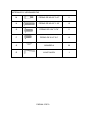
COM
P
A
PONENT
S
A
RT
A
B
C
D
E
A
S
S
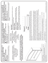
FIGUR
E
S
SEMB
L
WI
E
PA
G
L
Y INST
R
CKER
B
DESC
R
TAB
L
RIGH
T
LEF
T
BAC
K
MIDDL
G
E 1 OF 9
R
UCTIO
B
AR
R
IPTION
L
E TOP
T
PANEL
T
PANEL
K
PANEL
E PANEL
NS
QTY
1
1
1
1
1
SKU# 68636371

COM
P
A
PONENT
S
A
RT
F
G
H
I
J
K
L
S
FIGUR
E
E
D
O
PA
G
DESC
R
RIGH
T
LEF
T
BOTT
O
BOTT
L
SID
E
O
OR’S B
O
META
L
G
E 2 OF 9
R
IPTION
T
SHELF
SHELF
O
M SHELF
L
E RACK
E
DOOR
O
TTOM S
H
L
FRAME
H
ELF
QTY
1
1
1
2
1
1
1

HAR
D
D
WARET
O
M
N
O
P
Q
R
O
OLS
PA
G
M0.24”*
0
M0.24”*
1
0.24”*0
.
0.24”*
0
WA
S
ALLEN
G
E 3 OF 9
0
.47” BOL
T
1
.38’’ BOL
T
.
79” BOLT
0
.6” BOLT
S
HER
WRENCH
T
T
2
15
2
13
30
1

S
T
A.
B.
C.
N.
Q.
R.
B.
C.
D.
N.
Q.
R.
T
EP
1
2
Place
t
Right
P
Wash
e
Attach
by usi
n
t
he Table
T
P
anel (B)
a
e
rs (Q) an
d
the Back
n
g Washer
s
PA
G
T
op (A) fa
c
a
nd Left P
d
M0.24’’*1
Panel (D)
s
(Q) and
M
G
E 4 OF 9
e down o
n
anel (C) t
o
.38’’Bolts
(
to the Rig
M
0.24”*1.
3
n
a non-ab
r
o
the Tabl
e
(
N). Hand
t
h
t Panel (
B
3
8”Bolts (
N
r
asive sur
f
e
Top (A)
b
tighten on
B
) and Le
f
N
).Hand ti
g
f
ace.
A
ttac
b
y insertin
g
l
y.
f
t Panel (
C
g
hten only.
h
g
C
)

S
T
A.
D.
E.
N.
Q.
R.
B.
C.
E.
F.
H.
G.
P.
Q.
R.
T
EP
3
4
Attach
by usi
n
Attach
by usi
n
(G) to
and M
the Middl
n
g Washe
r
the Right
n
g Washe
r
the Left
P
0.24”*0.6
0
P
A
e Panel (
E
r
s (Q) and
Shelf (F)
t
r
s (Q) and
P
anel (C)
a
0
”Bolts (P)
.
A
GE 5 OF
E
) to the
B
M0.24”*1.
t
o the Rig
h
M0.24”*0.
a
nd Middl
e
.
Hand tig
h
9
B
ack Pane
l
3
8”Bolts (
N
h
t Panel (
B
6
0”Bolts (
P
Panel (E
)
h
ten only.
l (D) and
T
N
).Hand ti
g
B
) and Mi
d
P
). Attach
)
by using
T
able Top
g
hten only
.
d
dle panel
t
he Left S
h
Washers
(
(A)
.
(E)
h
elf
(
Q)

S
T
5
B.
C.
D.
H.
P.
Q.
R.
J.
K.
N.
O.
Q.
R.
T
EP
6
Conne
c
Back
P
Hand t
Place
t
Attach
Wash
e
Hand t
c
t the Bot
t
P
anel (D)
w
i
ghten onl
y
t
he item in
the Side
e
rs (Q) a
n
i
ghten onl
y
PA
G
t
om Shelf
(
w
ith Wash
e
y
.
the uprig
h
Doo
r
(J
)
n
d M0.24
”
y
.
G
E 6 OF 9
(
H) to Rig
h
e
rs (Q) an
d
h
t position.
)
to Door
’
”
*0.79”Bol
t
h
t Panel (
B
d
M0.24”*0
’
s Bottom
t
s (O), M
0
B
), Left Pa
0
.60”Bolts
(
Shelf (K
0.24”*1.3
8
nel (C) an
d
(
P).
) by usin
g
8
”Bolts (N
)
d
g
)
.

S
T
B
C
E
J
K
M
K.
L.
T
EP
7
8
Conne
c
M0.24
”
Attach
c
t the Sid
e
”
*0.47”Bolt
the Metal
PA
G
e
Door (J)
t
t
s (M). Ha
n
Frame (L)
G
E 7 OF 9
t
o Left pan
e
n
d tighten
o
onto the
D
e
l (C) and
o
nly.
D
oor’s Bot
t
Middle Pa
t
om Shelf
(
nel (E) wit
(
K).
h

ST
9
I
10
EP
9
Slip the
and Mid
(I) betw
e
Use All
e
tighteni
n
WICKE
R
Side Doo
r
dle Panel
e
en Right
P
e
n Wrenc
h
n
g may s
t
R
BAR.
P
r
’s (J) ribb
o
(E). Clos
e
P
anel (B)
a
h
(R) to ti
g
t
rip bolts
a
PA
GE 8 O
F
o
ns onto t
e
the Side
a
nd Middl
e
g
hten all b
a
nd wash
e
F
9
he hooks
o
Doo
r
(J).
P
e
Panel (E
)
olts. Do n
e
rs. Now
on the Le
f
P
lace the
B
)
.
ot over ti
g
you hav
e
f
t Panel (
C
B
ottle Rac
g
hten. Ov
e
e
your ne
w
C
)
k
e
r
w

Cleaning and Maintenance
●Clean with mild soap and water, rinse thoroughly, and dry completely. Do not use
bleach, acid, or other solvents on this item.
●We recommend the use of furniture covers to protect this item when not in use.
●Inspect and tighten all bolts on a regular basis to ensure proper performance and
safety.
●In order to prolong the life and beauty of your Wicker Bar Table,we recommend
storing it in a dry and protected area during off season periods.
PAGE 9 OF 9

DIRECTIVES D’ASSEMBLAGE
BAR EN OSIER
COMPOSANTES
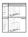
PIÈCE FIGURE DESCRIPTION QTÉ
A PLATEAU DE TABLE 1
B PANNEAU DROITE 1
C PANNEAU GAUCHE 1
D PANNEAU ARRIÈRE 1
E PANNEAU MILIEU 1
PAGE 1 DE 9
UGS N 68636371

COMPOSANTES
PIÈCE FIGURE DESCRIPTION QTÉ
F
TABLETTE DROITE 1
G TABLETTE GAUCHE 1
H
TABLETTE DU BAS 1
I
RÂTELIER À BOUTEILLES 2
J
PORTE LATÉRALE 1
K
TABLETTE INFÉRIEURE DE
PORTE 1
L
CADRE EN MÉTAL 1
PAGE 2 DE 9

QUINCAILLERIE ET OUTILS
M BOULON M 0,24 po x 0,47 po 2
N BOULONM 0,24 po x 1,38 po 15
O BOULON 0,24 po x 0,79 po 2
P BOULON 0,24 po x 0,6 po 13
Q RONDELLE 30
R CLÉ HEXAGONALE 1
PAGE 3 DE 9

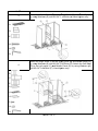
Étape
1
Placer le plateau de table (A) à l’envers sur une surface non
abrasive. Fixer le panneau droite (B) et le panneau gauche (C) au
plateau de table (A) en insérant les rondelles (Q) et les boulons M
0,24 po x 1,38 po (N). Serrer à la main uniquement.
A.
B.
C.
N.
Q.
R.
2 Fixer lepanneau arrière (D) au panneau droite (B) et le panneau
gauche (C) en utilisant les rondelles (Q) et les boulons M 0,24 po x
1,38 po (N). Serrer à la main uniquement.
B.
C.
D.
N.
Q.
R.
PAGE 4 DE 9

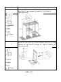
ÉTAPE
3 Fixer lepanneau du milieu (E) au panneau arrière (D) et le plateau de
table (C) en utilisant les rondelles (Q) et les boulons M 0,24 po x 1,38
po (N). Serrer à la main uniquement.
A.
D.
E.
N.
Q.
R.
4
Fixer latablette droite (F) au panneau droite (B) et le panneau du
milieu (E) en utilisant les rondelles (Q) et les boulons M 0,24 po x 0,60
po (N). Fixer la tablette gauche (G) au panneau gauche (C) et le
panneau du milieu (E) en utilisant les rondelles (Q) et les boulons M
0,24 po x 0,60 po (P). Serrer à la main uniquement.
B.
C.
E.
F.
H.
G.
P.
Q.
R.
PAGE 5 DE 9

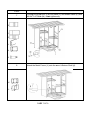
ÉTAPE
5 Fixer la tablette inférieure (H) au panneau droite (B), panneau de
gauche (C) et au panneau arrière (D) en utilisant les rondelles (Q) et
les boulons M 0,24 po x 0,60 po (P).
Serrer à la main uniquement.
B.
C.
D.
H.
P.
Q.
R.
6
Mettre l’article debout.
Fixer la Porte latérale (J) à la tablette inférieure de la porte (K) à
l’aide des rondelles (Q) et des boulons M 0,24 po x 0,79 po (O), M
0,24 po x1,38 po (N). Serrer à la main uniquement.
J.
K.
N.
O.
Q.
R.
PAGE 6 DE 9

ÉTAPE
7 Raccorder la porte latérale (J) au panneau gauche (C) et le panneau
du milieu (E) avec des boulons M 0,24 po x 0,47 po (M). Serrer à la
main uniquement.
B
C
E
J
K
M
8 Fixer le cadre métallique (L) à la tablette inférieure de la porte (K).
K.
L.
PAGE 7 DE 9

ÉTAPE
9
Glisser les rubans de la porte latérale (J) sur les crochets du panneau
gauche (C) et le panneau du milieu (E). Fermer la porte latérale (J).
Placer le râtelier à bouteille (I) entre le panneau droit (B) et le panneau
du milieu (E).
I
10 Utiliser une clé hexagonale (R) pour serrer tous les boulons. Ne pas
trop serrer. Trop serrer risque de détruire le pas des boulons et des
rondelles. Vous avez maintenant un nouveau BAR EN OSIER.
PAGE 8 DE 9

Nettoyage et entretien
• Nettoyer avec du savon doux et de l'eau, rincer soigneusement et bien sécher.
Ne pas utiliser de javellisant, d’acide ou autres solvants sur cet article.
• Nous recommandons l’usage de protections à meubles pour protéger cet article
entre les utilisations.
• Vérifier l’état et serrer tous les boulons régulièrement pour garantir l’utilisation et
la sécurité.
• Afin de prolonger la durée et la beauté de votre table de bar en osier, nous vous
recommandons de la ranger dans un endroit sec et protégé pendant les
périodes hors saison.
PAGE 9 DE 9

INSTRUCCIONES DE ENSAMBLADO
MESA DE BAR DE MIMBRE
COMPONENTES
PARTE FIGURA DESCRIPCIÓN CANTIDAD
A TABLERO 1
B PANEL DERECHO 1
C PANEL IZQUIERDO 1
D
PANEL POSTERIOR 1
E PANEL CENTRAL 1
PÁGINA 1 DE 9
n. de SKU: 68636371

COMPONENTES
PARTE FIGURA DESCRIPCIÓN CANTIDAD
F
ESTANTE DERECHO 1
G ESTANTE IZQUIERDO 1
H
ESTANTE INFERIOR 1
I
PORTABOTELLAS 2
J
PUERTA LATERAL 1
K
ESTANTE INFERIOR DE LA
PUERTA 1
L
MARCO DE METAL 1
PÁGINA 2 DE 9

MATERIALES Y HERRAMIENTAS
M PERNO DE M0.24”*0.47” 2
N PERNO DE M0.24”*1.38” 15
O
PERNO DE 0.24”*0.79” 2
P PERNO DE 0.24”*0.6” 13
Q ARANDELA 30
R LLAVE ALLEN 1
PÁGINA 3 DE 9

PASO
1
Coloque el tablero (A) boca abajo sobre una superficie no abrasiva.
Fije el panel derecho (B) y el panel izquierdo (C) al tablero (A)
insertando arandelas (Q) y pernos de M0.24’’*1.38’’ (N). Solo ajustar
a mano.
A.
B.
C.
N.
Q.
R.
2
Fije el panel posterior (D) al panel derecho (B) y al panel izquierdo (C)
usando arandelas (Q) y pernos de M0.24”*1.38” (N). Solo ajustar a
mano.
B.
C.
D.
N.
Q.
R.
PÁGINA 4 DE 9

PASO
3 Fije el panel central (E) al panel posterior (D) y al tablero (A) usando
arandelas (Q) y pernos de M0.24”*1.38” (N). Solo ajustar a mano.
A.
D.
E.
N.
Q.
R.
4
Fije el estante derecho (F) al panel derecho (B) y al panel central (E)
usando arandelas (Q) y pernos de M0.24”*0.60” (P). Fije el estante
izquierdo (G) al panel izquierdo (C) y al panel central (E) usando
arandelas (Q) y pernos de M0.24”*0.60” (P). Solo ajustar a mano.
B.
C.
E.
F.
H.
G.
P.
Q.
R.
PÁGINA 5 DE 9

PASO
5 Fije el estante inferior (H) al panel derecho (B), panel izquierdo (C) y
al panel posterior (D) con arandelas (Q) y pernos de M0.24”*0.60”
(P).
Solo ajustar a mano.
B.
C.
D.
H.
P.
Q.
R.
6
Coloque el artículo en la posición recta.
Fije la puerta lateral (J) al estante inferior de la puerta (K) usando
arandelas (Q), pernos de M0.24”*0.79” (O) y pernos de M0.24”*1.38”
(N). Solo ajustar a mano.
J.
K.
N.
O.
Q.
R.
PÁGINA 6 DE 9

PASO
7 Fije la puerta lateral (J) al panel izquierdo (C) y al panel central (E)
con pernos de M0.24”*0.47” (M). Solo ajustar a mano.
B
C
E
J
K
M
8 Fije el marco de metal (L) en el estante inferior de la puerta (K).
K.
L.
PÁGINA 7 DE 9

PASO
9
Deslice las bandas de la puerta lateral (J) en los ganchos del panel
izquierdo (C) y del panel central (E). Cierre la puerta lateral (J).
Coloque el portabotellas (I) entre el panel derecho (B) y el panel central
(E).
I
10
Use la llave Allen (R) para ajustar todos los pernos. No ajuste
demasiado. Si ajusta demasiado puede estropear los pernos y las
arandelas. Ahora tiene su nueva MESA DE BAR DE MIMBRE.
PÁGINA 8 DE 9

Limpieza y Mantenimiento
●Limpie con jabón suave y agua, enjuague bien y seque por completo. No use lejía,
ácido u otros solventes en este artículo.
● Se recomienda el uso de cubiertas para muebles para proteger este artículo
cuando no esté en uso.
● Inspeccione y ajuste todos los pernos regularmente para asegurar la seguridad y
el buen funcionamiento.
● Con el fin de prolongar la vida útil y belleza de su Mesa de Bar de Mimbre,
recomendamos que la guarde en un área seca y protegida durante los períodos
fuera de temporada.
PÁGINA 9 DE 9

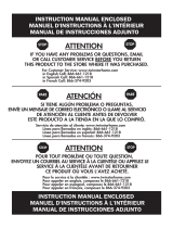
!Atención!
• No permita que ningún objeto afilado roce o toque la superficie del producto.
• No permita que hayan niños jugando alrededor mientras realiza la instalación.
• Por favor revise que todas las partes estén correctas antes de empezar con la
instalación.
• No asegure los pernos y tornillos hasta que la unidad completa haya sido
instalada y los ajustes se hayan establecido.
• Use solamente el Destornillador de cabeza hexagonal incluido.
NO UTILICE HERRAMIENTAS ELÉCTRICAS.
Las herramientas eléctricas pueden ajustar los tornillos demasiado y rasgar cables.
Para los tornillos:
1. Rondelle deben encontrarse al lado de la tudo.
2. Asegure cada tornillo hasta que sienta resistencia y los Espaciador empiecen
a presionar la tudo.
3. Asegure hasta un poco más de lo aceptado. No asegure los tornillos demasiado.
!Attention
• Ne laissez pas tout objet pointu de toucher ou de frotter la surface du produit.
• Lors de l'assemblage, de ne pas laisser les enfants jouer près de l'aire de travail.
• Veuillez confirmer que tous les éléments sont exacts avant d'entamer le
processus d'assemblage.
• Ne pas serrer tous les boulons et vis complètement jusqu'à l'unité entière a été
assemblé et mis en place.
• Utiliser les outils fournis. Ne pas utiliser des outils électriques.
Outils électriques peuvent renforcer des fils vis et bandes.
Pour chaque vis:
1. Arandela doit être à côté du tube.
2. Renforcer la résistance et chaque baiser jusqu'à ce que le espaceur
commence à pousser dans le tube.
3. Une rotation supplémentaire. Ne pas trop serrer.
!Warning!
• Do not let any sharp objects touch or rub the surface of the product.
• When assembling, do not let children play around the working area.
• Please confirm all parts are correct before starting the assembly process.
• Do not tighten all bolts and screws completely until the entire unit has been
assembled and set up.
• Use only the hex wrench provided. DO NOT USE POWER TOOLS.
Power tools can overtighten screws and strip threads
For each screw:
1. The washer must be next to the tube.
2. Tighten each screw until you meet resistance and spacer begins to push into
the tube.
3. Tighten one additional full rotation. DO NOT OVERTIGHTEN.
-
 1
1
-
 2
2
-
 3
3
-
 4
4
-
 5
5
-
 6
6
-
 7
7
-
 8
8
-
 9
9
-
 10
10
-
 11
11
-
 12
12
-
 13
13
-
 14
14
-
 15
15
-
 16
16
-
 17
17
-
 18
18
-
 19
19
-
 20
20
-
 21
21
-
 22
22
-
 23
23
-
 24
24
-
 25
25
-
 26
26
-
 27
27
-
 28
28


en otros idiomas
- français: YOTRIO Wicker Bar
- English: YOTRIO Wicker Bar
Artículos relacionados
Otros documentos
-
 Chimney Free 74303 Instrucciones de operación
-
 Delta Children Castille Bookcase/Hutch Assembly Instructions
-
none 62478 Guía de instalación
-
-
Twin-Star International WOOD FIREPLACE MANTEL 23MM1424 Instruction Manual Enclosed
-
Classic Flame 71388 Guía de instalación
-
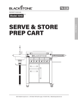 Blackstone 1948 Pro Series Prep/Serve and Store Cart El manual del propietario
-


