Hunter Fan Company 27181 Guía de instalación
- Tipo
- Guía de instalación

Installation Instructions:
1.Set the ceiling fan’s speed to the HIGH position
before installing this control.Do not change the ceil-
ing fan‘s speed setting after your speed control is
installed,as damage to your ceiling fan or All-Fan™
control may result.
2.Verify proper operation of the ceiling fan wall
switch before installation.Improper wiring can
damage the control,and will void the warranty.
3.Disconnect power to ceiling fan at the main electric
panel.Remove fuse or switch circuit breaker to OFF
position.
4.Refer to the Installation Figure for your All-Fan™
speed control.Remove wallplate to expose the wiring,
and disconnect the existing switch.
Install in a metal or plastic wallbox.
5.If 4 wall wires are visible,connect
each black wire lead to the All-Fan™
speed control’s black wire.If 2 wires
are visible,connect each to an All-Fan™
speed control lead.Use the wire nuts
supplied to make the connections.
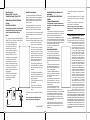
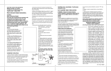
Refer to the Wiring Diagram,which
shows the proper connections.
If a ground wire is provided in your
electrical box,attach it to the ground
screw near the bottom of the mount-
ing plate.
6.Gently push wires and speed con-
trol into switch box.Attach the All-Fan™
speed control to switch box with the
two screws supplied.
7.Mount wallplate over control with
existing screws.
8.Move slider to the OFF position.
9.Restore power at main electrical
panel.
10.Operate ceiling fan moving slider to the desired
speed.
For best operation: select HIGH speed until
motor starts, then select desired speed.
Form 41312 (6/98)
Control deslizable para ventilador de 4
velocidades
Lea y guarde estas instrucciones
Cuidado:
! Riesgo de choque eléctrico
Todo el cableado y conexiones se deben hacer
de acuerdo con los códigos eléctricos nacionales
y locales.
Notas:
1.Para uso solamente con ventiladores de cielo raso que sean eléc-
tricamente reversibles y con capacidades de 1,6 A o menores.No se
debe usar con ninguna otra lámpara ni aparato eléctrico.
2.Se recomienda el uso de un circuito separado para los conjuntos
de luces de los ventiladores de cielo raso. Si el motor del ventilador
y el conjunto de luces se conectan juntos, el control de velocidad del
motor solamente se podrá usar cuando las luces estén apagadas.
Para usar el motor del ventilador y el conjunto de
luces juntos,este control se debe ajustar a alta
velocidad solamente.
Instrucciones de instalación:
1.Coloque el control de velocidad del ventilador
de cielo raso en la posición de Alta Velocidad
antes de instalar este control.No cambie el ajuste
de velocidad de su ventilador de cielo luego de
tener instalado el control de velocidad,puesto que
podría dañar su ventilador de cielo o el control All-
Fan.™
2.Verifique que el interruptor de pared del venti-
lador trabaja correctamente antes de la insta-
lación.Las conexiones incorrectas pueden dañar
el control y anularán la garantía.
3.Desconecte la energÌa eléctrica del ventilador
de cielo raso en el panel eléctrico principal.Retire
el fusible o coloque el disyuntor en la posición
“OFF”(apagado).
4.Vea la ilustración que muestra la instalación de
su control de velocidad All-Fan.™ Retire la placa
de la pared para exponer los cables y desconecte
el interruptor existente.
5.Si hay 4 alambres visibles,conecte cada alam-
bre del control de velocidad All-Fan™ a un alam-
bre negro.Si hay 2 alambres visibles,conecte cada uno a un
alambre del control de velocidad All-Fan.™ Use las tuercas de alam-
bres suministradas con el control para hacer las conexiones.
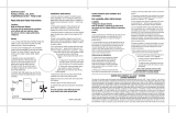
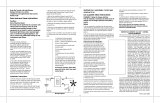
Consulte el Diagrama de Conexiones,que muestra la forma cor-
recta de conectar los alambres. Si su caja eléctrica contiene un
alambre de tierra,conéctelo al tornillo di tierra ubicado cerca de la
placa de montaje inferior.
6.Empuje los alambres y el control de velocidad,con mucho
cuidado,dentro de la caja del interruptor.Asegure el control de
velocidad All-Fan™ a la caja del interruptor con los dos tornillos
suministrados.
7.Monte la placa de la pared sobre el control con los tornillos
existentes.
8.Mueva la palanca deslizable a la posición “OFF”(apagada).
9.Vuelva a conectar la energía eléctrica en el panel eléctrico
principal.
10.Haga funcionar el ventilador de cielo raso moviendo la
palanca deslizable a la velocidad deseada.
Para la mejor operación: seleccione Alta Velocidad
hasta que el motor arranque y entonces seleccione la
velocidad deseada.
Quiet Fan Control
Ratings: 120 VAC, 1.6 A, 60 Hz
4-Speed Slide Control – Model 27181
Read and save these instructions.
Caution:
Risk of Electrical Shock!
All wiring must be performed in accordance with
national and local electrical codes. Use only to
control a single paddle-blade ceiling fan.
Notes:
1.For use only with electrically reversible ceiling fans
rated at 1.6 A or less.Not for use with any other light-
ing fixtures or electrical appliances.
2.Not for use with shaded-pole or
non-reversible motors.Not recom-
mended for use with the Hunter
Original.
®
For Hunter Original
®
series
fans,use Hunter control model
numbers 22691,26591,or 22798.
3.Separate wiring is recommended
for ceiling fan light kits.If the fan
motor and light kit are connected
together,this fan speed control may
be used only when the light kit is OFF.
To use the fan motor and light kit
together,this control must be set to
HIGH speed only.
4.MEDIUM and both LOW speeds
may vary from the ceiling fan’s
factory-set speeds because of
motor variations.
HUNTER FAN COMPANY ALL-FAN™ CONTROL
LIMITED WARRANTY
The Hunter Fan Company makes the following limited warranty
to the original purchaser of the ALL-FAN™ Control (“Control”):
Your Control is warranted to be free from defects in material and
workmanship for a period of one year from the
date of sale. If the Control malfunctions or fails
within the warranty period due to a defect in
material or workmanship we will replace it free
of charge. IF THE ORIGINAL PURCHASER
CEASES TO OWN THE CONTROL, THIS WAR-
RANTY AND ANY IMPLIED WARRANTY,
INCLUDING BUT NOT LIMITED TO ANY
IMPLIED WARRANTY OF MERCHANTABILITY
OR FITNESS FOR A PARTICULAR PURPOSE,
ARE VOIDED. THIS WARRANTY IS IN LIEU OF
ALL OTHER EXPRESS WARRANTIES. THE
DURATION OF ANY IMPLIED WARRANTY,
INCLUDING, BUT NOT LIMITED TO, ANY
IMPLIED WARRANTY OF MERCHANTABILITY
OR FITNESS FOR A PARTICULAR PURPOSE, IN
RESPECT TO ANY CONTROL, IS EXPRESSLY
LIMITED TO THE PERIOD OF THE EXPRESS
WARRANTY SET FORTH ABOVE FOR SUCH
CONTROL. This warranty excludes malfunctions
or failures which were caused by repairs by per-
sons not authorized by us, mishandling,
improper installation, modifications, or damage
to the Control while in your possession, or
unreasonable use. This warranty does not apply
to batteries or to deterioration or damage to the
product caused by the use of faulty batteries. To
obtain a replacement, return your Control
postage prepaid along with proof of purchase to Hunter Fan
Company Service Department at 2500 Frisco Avenue, Memphis,
Tennessee 38114. IN NO EVENT SHALL HUNTER FAN COMPANY
BE LIABLE FOR CONSEQUENTIAL OR INCIDENTAL DAMAGES.
SOME STATES DO NOT ALLOW LIMITATIONS ON HOW LONG AN
IMPLIED WARRANTY LASTS OR THE EXCLUSION OR LIMITA-
TIONS OF INCIDENTAL OR CONSEQUENTIAL DAMAGES SO THE
ABOVE LIMITATIONS OR EXCLUSIONS MAY NOT APPLY TO
YOU. THIS WARRANTY GIVES YOU SPECIFIC LEGAL RIGHTS
AND YOU MAY ALSO HAVE OTHER RIGHTS WHICH VARY FROM
STATE TO STATE.
Wiring Diagram
120VAC
60Hz
Black
Hot
Neutral
Black
Fan
Transcripción de documentos
Quiet Fan Control Ratings: 120 VAC, 1.6 A, 60 Hz 4-Speed Slide Control – Model 27181 Read and save these instructions. Caution: Risk of Electrical Shock! All wiring must be performed in accordance with national and local electrical codes. Use only to control a single paddle-blade ceiling fan. Notes: 1. For use only with electrically reversible ceiling fans rated at 1.6 A or less. Not for use with any other lighting fixtures or electrical appliances. 2. Not for use with shaded-pole or non-reversible motors. Not recommended for use with the Hunter Original.® For Hunter Original® series fans, use Hunter control model numbers 22691, 26591, or 22798. Installation Instructions: 1. Set the ceiling fan’s speed to the HIGH position before installing this control. Do not change the ceiling fan‘s speed setting after your speed control is installed, as damage to your ceiling fan or All-Fan™ control may result. 2. Verify proper operation of the ceiling fan wall switch before installation. Improper wiring can damage the control, and will void the warranty. 3. Disconnect power to ceiling fan at the main electric panel. Remove fuse or switch circuit breaker to OFF position. 4. Refer to the Installation Figure for your All-Fan™ speed control. Remove wallplate to expose the wiring, and disconnect the existing switch. Install in a metal or plastic wallbox. 5. If 4 wall wires are visible, connect each black wire lead to the All-Fan™ speed control’s black wire. If 2 wires are visible, connect each to an All-Fan™ speed control lead. Use the wire nuts supplied to make the connections. Refer to the Wiring Diagram, which shows the proper connections. 3. Separate wiring is recommended for ceiling fan light kits. If the fan motor and light kit are connected together, this fan speed control may be used only when the light kit is OFF. To use the fan motor and light kit together, this control must be set to HIGH speed only. If a ground wire is provided in your electrical box, attach it to the ground screw near the bottom of the mounting plate. 6. Gently push wires and speed control into switch box. Attach the All-Fan™ speed control to switch box with the two screws supplied. 4. MEDIUM and both LOW speeds may vary from the ceiling fan’s factory-set speeds because of motor variations. 7. Mount wallplate over control with existing screws. 8. Move slider to the OFF position. 9. Restore power at main electrical panel. Black Hot Black Fan 120VAC 60Hz 10. Operate ceiling fan moving slider to the desired speed. For best operation: select HIGH speed until motor starts, then select desired speed. Neutral Wiring Diagram Form 41312 (6/98) Control deslizable para ventilador de 4 velocidades 7. Monte la placa de la pared sobre el control con los tornillos existentes. Lea y guarde estas instrucciones 8. Mueva la palanca deslizable a la posición “OFF” (apagada). Cuidado: ! Riesgo de choque eléctrico 9. Vuelva a conectar la energía eléctrica en el panel eléctrico principal. Todo el cableado y conexiones se deben hacer de acuerdo con los códigos eléctricos nacionales y locales. Notas: 1. Para uso solamente con ventiladores de cielo raso que sean eléctricamente reversibles y con capacidades de 1,6 A o menores. No se debe usar con ninguna otra lámpara ni aparato eléctrico. 2. Se recomienda el uso de un circuito separado para los conjuntos de luces de los ventiladores de cielo raso. Si el motor del ventilador y el conjunto de luces se conectan juntos, el control de velocidad del motor solamente se podrá usar cuando las luces estén apagadas. Para usar el motor del ventilador y el conjunto de luces juntos, este control se debe ajustar a alta velocidad solamente. Instrucciones de instalación: 1. Coloque el control de velocidad del ventilador de cielo raso en la posición de Alta Velocidad antes de instalar este control. No cambie el ajuste de velocidad de su ventilador de cielo luego de tener instalado el control de velocidad, puesto que podría dañar su ventilador de cielo o el control AllFan.™ 2.Verifique que el interruptor de pared del ventilador trabaja correctamente antes de la instalación. Las conexiones incorrectas pueden dañar el control y anularán la garantía. 3. Desconecte la energÌa eléctrica del ventilador de cielo raso en el panel eléctrico principal. Retire el fusible o coloque el disyuntor en la posición “OFF” (apagado). 4.Vea la ilustración que muestra la instalación de su control de velocidad All-Fan.™ Retire la placa de la pared para exponer los cables y desconecte el interruptor existente. 5. Si hay 4 alambres visibles, conecte cada alambre del control de velocidad All-Fan™ a un alambre negro. Si hay 2 alambres visibles, conecte cada uno a un alambre del control de velocidad All-Fan.™ Use las tuercas de alambres suministradas con el control para hacer las conexiones. Consulte el Diagrama de Conexiones, que muestra la forma correcta de conectar los alambres. Si su caja eléctrica contiene un alambre de tierra, conéctelo al tornillo di tierra ubicado cerca de la placa de montaje inferior. 6. Empuje los alambres y el control de velocidad, con mucho cuidado, dentro de la caja del interruptor.Asegure el control de velocidad All-Fan™ a la caja del interruptor con los dos tornillos suministrados. 10. Haga funcionar el ventilador de cielo raso moviendo la palanca deslizable a la velocidad deseada. Para la mejor operación: seleccione Alta Velocidad hasta que el motor arranque y entonces seleccione la velocidad deseada. HUNTER FAN COMPANY ALL-FAN™ CONTROL LIMITED WARRANTY The Hunter Fan Company makes the following limited warranty to the original purchaser of the ALL-FAN™ Control (“Control”): Your Control is warranted to be free from defects in material and workmanship for a period of one year from the date of sale. If the Control malfunctions or fails within the warranty period due to a defect in material or workmanship we will replace it free of charge. IF THE ORIGINAL PURCHASER CEASES TO OWN THE CONTROL, THIS WARRANTY AND ANY IMPLIED WARRANTY, INCLUDING BUT NOT LIMITED TO ANY IMPLIED WARRANTY OF MERCHANTABILITY OR FITNESS FOR A PARTICULAR PURPOSE, ARE VOIDED. THIS WARRANTY IS IN LIEU OF ALL OTHER EXPRESS WARRANTIES. THE DURATION OF ANY IMPLIED WARRANTY, INCLUDING, BUT NOT LIMITED TO, ANY IMPLIED WARRANTY OF MERCHANTABILITY OR FITNESS FOR A PARTICULAR PURPOSE, IN RESPECT TO ANY CONTROL, IS EXPRESSLY LIMITED TO THE PERIOD OF THE EXPRESS WARRANTY SET FORTH ABOVE FOR SUCH CONTROL. This warranty excludes malfunctions or failures which were caused by repairs by persons not authorized by us, mishandling, improper installation, modifications, or damage to the Control while in your possession, or unreasonable use. This warranty does not apply to batteries or to deterioration or damage to the product caused by the use of faulty batteries. To obtain a replacement, return your Control postage prepaid along with proof of purchase to Hunter Fan Company Service Department at 2500 Frisco Avenue, Memphis, Tennessee 38114. IN NO EVENT SHALL HUNTER FAN COMPANY BE LIABLE FOR CONSEQUENTIAL OR INCIDENTAL DAMAGES. SOME STATES DO NOT ALLOW LIMITATIONS ON HOW LONG AN IMPLIED WARRANTY LASTS OR THE EXCLUSION OR LIMITATIONS OF INCIDENTAL OR CONSEQUENTIAL DAMAGES SO THE ABOVE LIMITATIONS OR EXCLUSIONS MAY NOT APPLY TO YOU. THIS WARRANTY GIVES YOU SPECIFIC LEGAL RIGHTS AND YOU MAY ALSO HAVE OTHER RIGHTS WHICH VARY FROM STATE TO STATE.-
 1
1

Hunter Fan Company 27181 Guía de instalación
- Tipo
- Guía de instalación
en otros idiomas
Artículos relacionados
Otros documentos
-
 Hunter Fan 27183 El manual del propietario
-
 Hunter Fan 27180 Manual de usuario
-
 Hunter Fan 27182 El manual del propietario
-
 Hunter Fan 22691 Manual de usuario
-
 Hunter Fan 27186 Manual de usuario
-
 Hunter Fan 27206 El manual del propietario
-
 Hunter Fan 27181 El manual del propietario
-
Hunter Fan 99814 El manual del propietario
-
 Hunter Fan 27180 El manual del propietario


