
Hunter Fan Co. © 2010 41317-01 r090111
Fig. 2-A Fig. 2-B
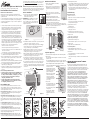
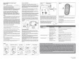
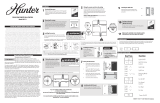
Figure 2
Ceiling
Plate
Receiver
Canopy
Antenna
Ceiling
Plate
Receiver
Canopy
Antenna
Ceiling
Bracket
Receiver
Receiver
Placement
On Motor
Fan
Motor
Motor
Mounting
Plate
Antenna
Ceiling
Bracket
Receiver
Fan Body
Antenna
Antenna
Receiver
Canopy
Bracket
Canopy Hands-Free
TM
Canopy Low Prole I Low Prole II Bracket Hanger
Fig. 2-C Fig. 2-D
Fig. 2-E
2-Wire Fan & Light Control Model 27186
120 VAC, 60 Hz,1.0 Amp Fan, 300 Watts incandescent light.
Operation (Figure 6.):
1. Turn ON the wall switch. The light will turn ON at maximum brightness.
2. Light Operation:
• Press and quickly release the light button on the wall control to turn the
light OFF or ON.
• Press and hold the light button for more than 1 second to turn the light
ON and gradually dim the light from maximum brightness down to OFF.
• Release the light button when the desired light level is reached.
• Continue to hold the light button to repeat the cycle (Maximum - Light
Level Decrease - OFF)
• Turning the light OFF resets the
dimming function. The next press
of the light button will turn the
light on to full brightness.
• After a power outage, the light
will remain off after power is
restored. Press and quickly
release the light button once to
turn the light back on after a
power outage.
3. Fan Operation:
• Press the High, Medium, or Low
speed buttons to turn the ceiling
fan ON at the desired speed.
• Press the fan OFF key to turn the
ceiling fan OFF.
• For best operation: Allow the
ceiling fan motor to start on
High, then select the desired
speed.
Read and Save these Instructions
Caution: Risk of Electrical Shock!
All wiring must be performed in accordance with national and local
electrical codes. If you are unfamiliar with the wiring codes, you should use
a qualied electrician.
To avoid overheating and possible damage to other equipment, do not install
to control a receptacle, uorescent light xture, motor operated appliance,
or transformer-supplied appliance. Use only to control one ceiling fan and
incandescent light xture.
1. This device complies with Part 15 of the FCC Rules. Operation is subject
to the following two conditions: (1) this device may not cause harmful
interference, and (2) this device must accept any interference received,
including interference that may cause undesired operation.
2. This equipment has been tested and found to comply with the limits for
a Class B digital device, pursuant to Part 15 of the FCC Rules. These
limits are designed to provide reasonable protection against harmful
interference in a residential installation. This equipment generates, uses
and can radiate radio frequency energy and, if not installed and used in
accordance with the instructions, may cause harmful interference to radio
communications. However, there is no guarantee that interference will not
occur in a particular installation. If this equipment does cause harmful
interference to radio or television reception, which can be determined by
turning the equipment off and on, the user is encouraged to try to correct
the interference by one or more of the following measures:
• Reorient or relocate the receiving antenna.
• Increase the separation between the equipment and receiver.
• Connect the equipment into an outlet on a circuit different from the one
the receiver is connected to.
• Consult the dealer or an experienced radio/TV technician for help.
3. For use only with electrically reversible ceiling fans rated at 1.0 amp or
less, and fan incandescent light kits rated at 300 watts or less.
4. Not for use with shaded-pole motors. Not recommended for use with the
Hunter Original
®
. For Hunter Original
®
series fans, use Hunter control
model numbers 27187, 22691, or 27189.
5. Medium and Low fan speeds are determined by the All-Fan
®
control and
thus may vary from the factory settings due to normal motor variations.
6. For use with Hunter Hanging systems (excludes Hunter Original) on
angled ceilings up to 34 degree pitch.
7. Any changes or modications to this equipment not expressly approved
by Hunter Fan Company will void the user’s authority to operate the
equipment.
Before Installing the All-Fan® Control:
1. Use the pull chain to set the fan speed to the HIGH position
before installation. DO NOT use the pull chain to change
the fan speed after installation, as damage to your ceiling
fan may result. The speed of the fan should only be
changed by the All-Fan® control.
2. Set the ceiling fan light kit to the ON position before
installing the All-Fan® control. The light level should only
be changed by the All-Fan® control.
Receiver Installation:
1. Disconnect power to the ceiling fan and light kit at
the main electrical panel. Remove fuse or move
circuit breaker to the OFF position.
IMPORTANT! Before installing this control, change
the factory default DIP switch settings to your own
unique code. Refer to Figure 1. Be sure the DIP switch
positions of the transmitter and receiver match, or the
ceiling fan will not function.
2. Select different combinations of DIP switches to prevent misoperation due
to other remote control fans, garage door openers, etc.
3. Determine your ceiling fan mounting type (Figure 2). Most installations
will be one of these ve types: Canopy Hanger, Hunter Hands-Free
TM
Canopy, Low Prole Styles I or II, or Bracket Hanger.
4. Install the ceiling fan according to its instructions, up to the point of
making the electrical connections. Connect receiver to ceiling fan
according to the mounting type as instructed in Figure 2.
5. If the fan is already installed, reverse the installation procedure to the
point of disconnecting the fan wiring. Connect receiver to ceiling fan
according to the mounting type as instructed in Figure 2.
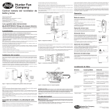
6. Use the 2 large wire nuts supplied to connect the receiver and house
wiring, then use the 3 small wire connectors supplied to connect the
receiver and ceiling fan wiring. Refer to the Wiring Diagram in Figure 3.
7. Be sure the antenna is positioned securely, so it does not interfere with
the ceiling fan motor. Refer to Figure 2. Do not modify or damage the
antenna wire, as control performance may be reduced. After securing the
receiver, antenna, and wiring, nish hanging the ceiling fan according to
its instructions.
Wall Control Installation:
1. Remove rocker-style wallplate (not included) to
expose the wall wiring.
2. If 4 wires are visible, connect each black wire to an
All-Fan® lead. Use 2 of the large wire connectors
supplied to make the connections. Refer to Figure
5.
3. If there is a ground wire in your electrical box,
attach it to the ground screw near the bottom of the
mounting plate.
4. Gently push wires and wall control into the
electrical box. Attach the All-Fan® control to the
switch box with the two screws provided.
5. Verify that the master switch is in the OFF position.
Press inward on each side of the wall control to
remove the face cover. Set the DIP switches in the wall control to match
the DIP switches in the receiver. Figure 4. Install a 12-volt alkaline battery
(A23, MN21, or equivalent). Replace the face cover.
6. Restore power at the electrical panel.
Fan Installation Types
NOTE: Some fans may have considerable excess lead wire. For easier
canopy installation, cut the excess wire, leaving a minimum of 6 inches
remaining. Restrip the fan lead wires 1/2 inch. Place remaining excess wire
into the ceiling electrical box as needed.
Canopy Hanger (Fig. 2-A): Place receiver in canopy. Connect wiring
as shown in Figure 3. Extend antenna through one of the ceiling plate
openings (approximately 3-6”).
Hunter Hands-Free
TM
Canopy (Fig. 2-B): Connect wiring as shown
in Figure 3. Place receiver inside mounting bracket. (On some Wisper
Wind
TM
models, the receiver must rest across the bottom of the mounting
bracket.) Extend antenna above the ceiling mounting bracket (approximately
3-6”).
Low Prole Style I (Fig. 2-C): Attach the receiver to the motor
mounting plate with 12” cable ties (not included). Cut off any extra cable
tie. Connect wiring as shown in Figure 3. Extend antenna through one of the
ceiling plate openings (approximately 3-6”).
Low Prole Style II (Fig. 2-D): Attach the receiver to the ceiling
bracket with 12” cable ties (not included). Trim off the excess cable tie
length. Connect wiring as shown in Figure 3. Extend antenna above the
ceiling mounting bracket (approximately 3-6”).
Bracket Hanger (Fig. 2-E): Starting with the antenna wire, slide
receiver inside mounting bracket. If a ground wire mounting screw prevents
the receiver from sliding into the bracket, move ground wire and screw to
ON
1 234
Figure 1.
ON
1 234
an unused hole at the top of the bracket or secure with a canopy mounting
screw. The bracket must remain properly grounded. Connect wiring as
shown in Figure 3. Extend antenna above the receiver (approximately 3 –
6˝).
Cable Tie Routing for Low Prole Fans (Figs. 2-C, 2-D): Insert
cable tie through openings as shown. DO NOT insert the cable tie through
the inside of the receiver. The cable tie can be placed across the length or
width of the receiver to best match your fan installation type.
ON
1234
A23 or MN21 12volt
Figure 4.
Figure 5.
Black from Wall
Bare from Wall
Fan Light
Fan Off
Fan Low
Fan Medium
Fan High
Master On/OFF
Figure 6.
ON
1 234
Live In
Nuetral In
Fan Out
Light Out
Common Out
To Ceiling Wires
To Fan Wires
White Common
Red or Black/White Stripe
Black Wire
White Common
Black Power
Figure 3.
Antenna
4. Manual Light Switch Operation:
• To turn the lights ON without battery power to the wall control, turn OFF
the master switch for 5 seconds, then turn the master switch back ON.
The light will turn on at full brightnes, and the fan will remain OFF.
• For everyday operation, leave the wall switch ON. However, if the
control will not be used for an extended period of time (5 days or more),
turn the wall switch OFF.
Troubleshooting
Operates only at close range.
1. Signal blocked from reaching receiver.
• Extend antenna into ceiling box, or move it for better reception.
2. Battery too weak.
• Replace with new, 12 Volt alkaline battery.
Inconsistent operation.
1. Signal partially blocked from reaching receiver.
• Extend antenna into ceiling box, or move it for better reception.
2. RF interference.
• Turn OFF wall switch for 5 seconds, then turn back ON.
3. Continuing RF interference.
• Change dip switch settings to a different code in both Transmitter and
Receiver.
No functions operate.
1. Main Power not restored.
• Replace fuse. Turn ON circuit breaker. Turn ON wall switch.
2. Fan pull chain not set to High.
• Turn OFF power at wall switch or main electric panel.
• Set fan pull chain to High speed.
3. Light pull chain not set to ON.
• Set light kit to ON.
4. Receiver wiring incorrect.
• Verify wiring connections.
5. Transmitter and receiver dip switches do not match.
• Set transmitter and receiver to same dip switch setting.
6. Battery too weak.
• Replace with new, alkaline battery.
The Hunter Fan Company makes the following limited warranty to the
original purchaser of the ALL-FAN® Control (“Control”): Your Control
is warranted to be free from defects in material and workmanship for a
period of one year from the date of sale. If the Control malfunctions or fails
within the warranty period due to a defect in material or workmanship
we will replace it free of charge. IF THE ORIGINAL PURCHASER
CEASES TO OWN THE CONTROL, THIS WARRANTY AND ANY
IMPLIED WARRANTY, INCLUDING BUT NOT LIMITED TO ANY IMPLIED
WARRANTY OF MERCHANTABILITY OR FITNESS FOR A PARTICULAR
PURPOSE, ARE VOIDED. THIS WARRANTY IS IN LIEU OF ALL OTHER
EXPRESS WARRANTIES. THE DURATION OF ANY IMPLIED WARRANTY,
INCLUDING, BUT NOT LIMITED TO, ANY IMPLIED WARRANTY OF
MERCHANTABILITY OR FITNESS FOR A PARTICULAR PURPOSE, IN
RESPECT TO ANY CONTROL, IS EXPRESSLY LIMITED TO THE PERIOD OF
THE EXPRESS WARRANTY SET FORTH ABOVE FOR SUCH CONTROL.
This warranty excludes malfunctions or failures which were caused by
repairs by persons not authorized by us, mishandling, improper installation,
modications, or damage to the Control while in your possession,
or unreasonable use. This warranty does not apply to batteries or to
deterioration or damage to the product caused by the use of faulty batteries.
To obtain a replacement, return your Control postage prepaid along with
proof of purchase to Hunter Fan Company Service Department at 2500
Frisco Avenue, Memphis, Tennessee, USA, 38114. SOME AMERICAN
STATES AND CANADIAN PROVINCES DO NOT ALLOW: (1) LIMITATIONS
ON HOW LONG AN IMPLIED WARRANTY LASTS; OR (2) THE EXCLUSION
OR LIMITATION OF DIRECT, INDIRECT, SPECIAL, OR CONSEQUENTIAL
DAMAGES. SO THE ABOVE LIMITATION OR EXCLUSIONS MAY NOT
APPLY TO YOU. THIS WARRANTY GIVES YOU SPECIFIC LEGAL RIGHTS
AND YOU MAY ALSO HAVE OTHER RIGHTS WHICH VARY FROM STATE
TO STATE OR PROVINCE TO PROVINCE. IN CANADA, THIS WARRANTY
IS IN ADDITION TO ANY STATUTORY WARRANTIES CONTAINED IN
ANY APPLICABLE LEGISLATION AND THE TERMS OF THIS WARRANTY
ARE NOT INTENDED TO EXCLUDE OR LIMIT YOU RIGHTS UNDER THOSE
STATUTES.
HUNTER FAN COMPANY ALL-FAN
®
CONTROL
LIMITED WARRANTY

Hunter Fan Co. © 2010 41509-05 r090111
ON
1 234
Figure 1.
ON
1 234
Fig. 2-A Fig. 2-B
Figura 2
Placa de techo
Receptor
Campana
Antena
Placa de techo
Receptor
Campana
Antena
Soporte de techo
Receptor
Colocacion del
receptor
en el motor
Motor
del
ventilador
Placa de
montaje
del motor
Antena
Soporte de techo
Receptor
Motor del
ventilador
Antena
Antena
Receptor
Campana
Soporte
Suspensión De Campana Campana Hunter
Hands-Free
TM
Perl Bajo Estilo I Perl Bajo Estilo II Suspensión De Soporte
Fig. 2-C Fig. 2-D
Fig. 2-E
ON
1234
A23 or MN21 12volt
Figure 4.
Figure 5.
Black from Wall
Bare from Wall
ON
1234
Live In
Nuetral In
Fan Out
Light Out
Common Out
A los cables del techo
A los cables del
ventilador
Blanco común
Rojo o de rayas Negro/Blanco
Cable negro
Blanco Común
De Potencia Negro
Figura 3.
Antenna
Control de Ventilador y Luz Universal Hunter
Modelo 27186
Ventilador 120 VCA, 60 Hz,1.0 A, Lámpara incandescente de 300 Vatios
Lea Y Guarde Estas Instrucciones
Precaución: ¡Riesgo de choque eléctrico!
1. Este dispositivo cumple con la parte 15 de las reglas FCC. La operación está
sujeta a las siguientes dos condiciones: (1) este dispositivo no puede causar
una interferencia perjudicial, y (2) este dispositivo debe tolerar cualquier
interferencia recibida, incluyendo interferencias que puedan causar una
operación no deseada.
2. Este equipo se ha probado y cumple con los límites para un dispositivo digital
clase B, de acuerdo con la Parte 15 de las reglas FCC. Estos límites están
diseñados para proporcionar una protección razonable contra la interferencia
perjudicial en una instalación residencial. Este equipo genera, usa y puede
radiar energía de radio frecuencia, y si no se instala y usa de acuerdo con
las instrucciones, puede causar interferencia perjudicial a la comunicación
por radio. Sin embargo, no hay garantía de que no pueda producirse
interferencia en una instalación en particular. Si este equipo causa alguna
interferencia perjudicial a la recepción de radio o televisión, lo que puede
determinarse apagando y encendiendo el equipo, el usuario debe tratar de
corregir la interferencia aplicando una o más de las medidas siguientes:
• Reoriente o reubique la antena receptora.
• Aumente la separación entre el equipo y el receptor.
• Conecte el equipo en una salida de un circuito diferente del circuito en el
que está conectado el receptor.
• Consulte con su representante de ventas o con un técnico experimentado de
radio/TV.
3. Sólo para uso con ventiladores de techo con inversión de rotación, de 1.0
amperio o menos, y con conjuntos de lámparas incandescentes de 300 vatios
o menos.
4. No debe usarse con motores de polo sombreado. No se recomienda su uso
con el modelo Hunter Original®. Para los ventiladores de la serie Hunter
Original®, use los controles Hunter modelos 22691, 27187, o 27189.
5. Las velocidades media y baja del ventilador son determinadas por el control
y pueden diferir de los ajustes de fábrica debido a variaciones normales del
motor.
6. Para uso con sistemas de suspensión Hunter (excluye Hunter original) en
techos inclinados de hasta 34 grados.
7. Todo cambio o modicación a este equipo no aprobado expresamente por
Hunter Fan Company anulará la autorización del usuario para operar el
equipo.
Antes De Instalar El Control All-Fan
®
:
1. Use el interruptor tirador de cadena para establecer la velocidad del
ventilador a la posición ALTA antes de la instalación. No use el tirador de
cadena para cambiar la velocidad del ventilador después de la instalación,
ya que podría dañarse su ventilador o el control universal. La ventilador del
ventilador sólo debe cambiarse usando el control universal.
2. Fije el conjunto de luz del ventilador de techo en la posición ON antes de la
instalación. El nivel de iluminación sólo debe cambiarse usando el control
universal.
Tipos De Instalación De Ventilador:
NOTA: Algunos ventiladores pueden tener un considerable exceso de conduc-
tor. Para una instalación más fácil de la campana, corte el alambre en exceso
dejando un mínimo de 6” (15 cm.) Pele nuevamente los extremos de los
alambres del ventilador 1/2”. Coloque el alambre de exceso restante en la caja
eléctrica de techo según sea necesario.
Suspensión De Campana (Fig. 2-A): Coloque el receptor en la campana.
Conecte los alambres como se muestra en la Figura 3. Extienda la antena a
través de una de las aberturas de la placa de techo (aproximadamente entre 3”
y 6”).
Campana Hunter Hands-Free™ (Fig. 2-B): Conecte los alambres como
se muestra en la Figura 3. Coloque el receptor dentro de un soporte de montaje.
Extienda la antena por encima del soporte de montaje de techo (aproximada-
mente entre 3” y 6”).
Perl Bajo Estilo I (Fig. 2-C): Conecte el receptor a la placa de montaje del
motor con bridas de 12” (no incluidos). Corte toda brida excedente. Conecte los
alambres como se muestra en la Figura 3. Extienda la antena a través de una de
las aberturas de la placa de techo (aproximadamente entre 3” y 6”).
Perl Bajo Estilo II (Fig. 2-D): Conecte el receptor al soporte de techo con
bridas de 12” (no incluidos). Recorte el exceso de longitud de bridas. Conecte
los alambres como se muestra en la Figura 3. Extienda la antena por encima del
soporte de montaje de techo (aproximadamente entre 3” y 6”).
Suspensión De Soporte (Fig. 2-E) : Comenzando con el alambre de la
antena, deslice el receptor dentro del soporte de montaje. Si el tornillo de mon-
taje de un alambre de tierra evita que el receptor se deslice en el soporte, mueva
el alambre de tierra y atorníllelo en un agujero no utilizado en la parte superior
del soporte o asegúrelo con un tornillo de montaje de campana. El soporte debe
permanecer puesto a tierra adecuadamente. Conecte los alambres como se
muestra en la Figura 3. Extienda la antena encima del receptor (aproximada-
mente entre 5” y 8”).
Colocación De Sujetacables Para Ventiladores De Perl Bajo (Fig.
2-C, 2-D): Introduzca el sujetacables a través de las aberturas, tal como se
muestra. NO introduzca el sujetacables a través del interior del receptor. El
sujetacables puede colocarse longitudinal o transversalmente al receptor para
adaptarse mejor al tipo de instalación de su ventilador.
Instalación Del Receptor:
1. Desconecte la alimentación de energía al ventilador
de techo y al conjunto de luces en el panel eléctrico
principal. Retire el fusible o mueva el interruptor
automático a la posición de apagado.
¡IMPORTANTE! Antes de instalar este control, veri-
que los ajustes del conmutador DIP predeterminados
en fábrica. Vea la Figura 1. Asegúrese que las posiciones del conmutador DIP
del transmisor y del receptor coincidan, o el ventilador de techo no funcionará.
Seleccione diferentes combinaciones de los conmutadores DIP para evitar la
operación incorrecta debido a controles remotos de otros ventiladores.
2. Seleccione diferentes combinaciones de conmutadores DIP para evitar la
operación incorrecta debido a otros controles remotos de ventiladores,
puertas de garaje, etc.
3. Determine el tipo de montaje de su ventilador de techo (Figura 2). La mayoría
de instalaciones será uno de estos cuatro tipos: Suspensión de campana,
Campana Hunter Hands-Free
TM
, Perl bajo Estilos I y II, o Suspensión de
soporte.
4. Instale el ventilador de techo de acuerdo con sus instrucciones, hasta la
realización de las conexiones eléctricas. Conecte el receptor al ventilador de
techo de acuerdo con el tipo de montaje, como se indica en la Figura 2.
5. Si el ventilador ya está instalado, apague la alimentación en el panel
eléctrico principal. Invierta el procedimiento de instalación de acuerdo con
las instrucciones del ventilador, hasta el punto de desconectar el cableado del
ventilador. Conecte el receptor al ventilador de techo de acuerdo con el tipo
de montaje, como se indica en la Figura 2.
6. Use los 2 empalmes plásticos grandes suministrados para conectar al receptor
con el cableado ya existente, y luego los 3 pequeños para conectar el
receptor y el ventilador de techo. Consulte el Diagrama de cableado en la
Figura 3.
7. Asegúrese que la antena esté ubicada en forma segura para que no pueda
Instalación de control de pared:
1. Retire la placa del interruptor de balancín (no incluido) para hacer visible el
cableado.
2. Si hay 4 alambres visibles, conecte cada alambre
negro con un cable All-Fan®. Use 2 de los conectores
de alambres grandes suministrados para hacer las
conexiones. Consulte la Figura 5.
3. Si hay un alambre de tierra en su caja eléctrica,
conéctelo al tornillo de tierra cerca de la parte inferior
de la placa de montaje.
4. Suavemente empuje los alambres y el control de
pared dentro de la caja eléctrica. Conecte el control
All-Fan® a la caja del interruptor con los dos tornillos
suministrados.
5. Verique que el interruptor principal esté en la
posición OFF (apagado). Presione hacia adentro en
cada lado del control de pared para retirar la cubierta. Fije los conmutadores
DIP en el control de pared para que coincidan con los conmutadores DIP en el
receptor. Figura 4. Instale una batería alcalina de 12 voltios (A23, MN21, o
equivalente). Reinstale la cubierta.
6. Restaure la energía en el tablero eléctrico.
Operación:
1. Encienda el interruptor de pared. La luz se encenderá a su máximo brillo.
2. Operación de la luz:
• Presione y libere rápidamente
el botón de luz en el control de
pared para apagar o encender
la luz. (La luz se encenderá con
el máximo brillo)
• Presione y mantenga
presionado el botón de luz
por más de 1 segundo para
encender la luz y disminuir
desde el brillo máximo hasta
apagado.
• Suelte el botón de luz cuando
se alcance el nivel de luz
deseado.
• Continúe presionando el botón
de luz para repetir el ciclo.
(Máximo–reducción de nivel de
luz–APAGADO)
• Al apagar la luz se restablece
la función de atenuación
de luz. La próxima vez que
presione el botón de luz, se
encenderá al brillo máximo.
• Después de un corte de energía
eléctrica, la luz permanecerá
apagada después de que se restablezca la energía eléctrica. Presione
y suelte rápidamente el botón de luz una vez para encender la luz
nuevamente después de un corte de energía eléctrica.
3. Operación Del Ventilador:
• Poussez sur les boutons de vitesse High, Medium ou Low (haute, moyenne ou
basse) pour mettre en marche le ventilateur à la vitesse désirée.
• Poussez sur la touche OFF pour arrêter le ventilateur de plafond.
• Pour un fonctionnement sans problème du ventilateur : Faites démarrer le
moteur de ventilateur sur High (vitesse haute), puis choisissez la vitesse
désirée.
4. Operación manual del interruptor de luz:
• Para encender las luces sin alimentación de baterías al control remoto,
apague el interruptor principal por 5 segundos y luego enciéndalo otra vez.
La luz se encenderá al brillo máximo y el ventilador quedará apagado.
• Para la operación diaria, deje el interruptor de pared encendido. Sin
embargo, si el control no va a usarse por tiempo prolongado (5 días o
más), apague el interruptor de pared.
Opera sólo en un rango restringido.
1. La señal no puede alcanzar al receptor.
• Extienda la antena en la caja de techo, o muévala para obtener una mejor
recepción.
2. Batería demasiado débil.
• Reemplace con una batería alcalina nueva de 12 voltios.
Operación irregular.
1. La señal sólo alcanza parcialmente al receptor.
• Extienda la antena en la caja de techo, o muévala para obtener una mejor
recepción.
2. Interferencia de RF.
• Apague el interruptor de pared por 5 segundos y luego enciéndalo otra vez.
3. Interferencia continua de RF.
• Cambie los ajustes a un código diferente en el transmisor y en el receptor.
No opera ninguna función.
1. La alimentación principal no se ha restaurado.
• Reemplace el fusible. Encienda el interruptor automático. Encienda el
interruptor de pared.
2. La cadena del ventilador no está jada en Alta.
• Apague la alimentación en el interruptor de pared o en el tablero eléctrico
principal.
• Coloque los tiradores de cadena de los ventiladores en velocidad ALTA.
3. El tirador de la cadena de luz no está colocado en ON (encendido).
• Fije el conjunto de luces en ON.
4. Cableado de receptor incorrecto.
• Verique las conexiones del cableado.
5. Los ajustes del transmisor y el receptor no coinciden.
• Fije el transmisor y el receptor al mismo ajuste.
6. Batería demasiado débil.
• Reemplace con una batería alcalina nueva de 12 voltios.
LOCALIZACIÓN DE FALLAS
GARANTÍA LIMITADA DEL CONTROL DE HUNTER FAN
COMPANY
Hunter Fan Company establece la siguiente garantía limitada al comprador
original del Control (“Control”): Garantizamos que su Control no tendrá
defectos en materiales ni mano de obra por un año a partir de la fecha de
compra. Si el Control presenta un funcionamiento defectuoso o una avería
dentro del período de garantía debido a un defecto en el material o la
mano de obra, lo reemplazaremos en forma gratuita. SI EL COMPRADOR
ORIGINAL DEJA DE POSEER EL CONTROL, ESTA GARANTÍA Y
CUALQUIER GARANTÍA IMPLÍCITA, INCLUYENDO, PERO SIN LIMITARSE
A TODA GARANTÍA IMPLÍCITA DE COMERCIABILIDAD O IDONEIDAD
PARA UN PROPÓSITO PARTICULAR, QUEDA ANULADA. ESTA GARANTÍA
SUSTITUYE A TODAS LAS OTRAS GARANTÍAS EXPRESAS. LA DURACIÓN
DE TODA GARANTÍA IMPLÍCITA, INCLUYENDO PERO SIN LIMITARSE A
CUALQUIER GARANTÍA IMPLÍCITA DE COMERCIABILIDAD O IDONEIDAD
PARA UN PROPÓSITO PARTICULAR, RELACIONADA CON CUALQUIER
CONTROL, ESTÁ EXPRESAMENTE LIMITADA AL PERÍODO DE LA
GARANTÍA EXPRESA ESTABLECIDA ANTERIORMENTE PARA DICHO
CONTROL. Esta garantía excluye funcionamientos defectuosos o fallas
causados por reparaciones realizadas por personas no autorizadas por
nosotros, mal uso, instalación incorrecta, modicaciones, o daños al
Control mientras esté en su posesión, o por un empleo no razonable. Esta
garantía no se aplica a las baterías ni al deterioro o daño al producto
causado por el uso de baterías defectuosas. Para obtener un reemplazo,
devuelva su Control con el franqueo prepagado junto con una prueba de
su compra al Departamento de servicio de Hunter Fan Company, en 2500
Frisco Avenue, Memphis, Tennessee 38114. EN NINGÚN CASO HUNTER
FAN COMPANY SERÁ RESPONSABLE DE DAÑOS PERJUDICIALES O
ACCESORIOS. ALGUNOS ESTADOS NO PERMITEN LIMITACIONES
SOBRE LA DURACIÓN DE UNA GARANTÍA IMPLÍCITA O LA EXCLUSIÓN
O LIMITACIÓN DE DAÑOS ACCESORIOS O PERJUDICIALES, ASÍ QUE
LAS LIMITACIONES O EXCLUSIONES ANTES MENCIONADAS PUEDEN
NO APLICARSE A USTED. ESTA GARANTÍA LE DA DERECHOS LEGALES
ESPECÍFICOS, PERO USTED TAMBIÉN PUEDE TENER OTROS DERECHOS
QUE VARÍAN DE ESTADO A ESTADO.
Boton de la Luz
Ventilador Apagado
Baja Velocidad
Media Velocidad
Alta Velocidad
Interruptor Principal
Figure 6.
interferir con el motor del ventilador de techo. Consulte la Figura 2. No
modique ni dañe el alambre de la antena, ya que podría perjudicar el
funcionamiento del control. Después de asegurar el receptor, la antena y el
cableado, termine de suspender el ventilador de techo de acuerdo con las
instrucciones.
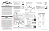
Transcripción de documentos
Read and Save these Instructions Cable Tie Routing for Low Profile Fans (Figs. 2-C, 2-D): Insert cable tie through openings as shown. DO NOT insert the cable tie through the inside of the receiver. The cable tie can be placed across the length or width of the receiver to best match your fan installation type. Caution: Risk of Electrical Shock! Receiver Installation: All wiring must be performed in accordance with national and local electrical codes. If you are unfamiliar with the wiring codes, you should use a qualified electrician. 1. Disconnect power to the ceiling fan and light kit at the main electrical panel. Remove fuse or move circuit breaker to the OFF position. IMPORTANT! Before installing this control, change the factory default DIP switch settings to your own unique code. Refer to Figure 1. Be sure the DIP switch positions of the transmitter and receiver match, or the ceiling fan will not function. 120 VAC, 60 Hz,1.0 Amp Fan, 300 Watts incandescent light. To avoid overheating and possible damage to other equipment, do not install to control a receptacle, fluorescent light fixture, motor operated appliance, or transformer-supplied appliance. Use only to control one ceiling fan and incandescent light fixture. 1. This device complies with Part 15 of the FCC Rules. Operation is subject to the following two conditions: (1) this device may not cause harmful interference, and (2) this device must accept any interference received, including interference that may cause undesired operation. 2. This equipment has been tested and found to comply with the limits for a Class B digital device, pursuant to Part 15 of the FCC Rules. These limits are designed to provide reasonable protection against harmful interference in a residential installation. This equipment generates, uses and can radiate radio frequency energy and, if not installed and used in accordance with the instructions, may cause harmful interference to radio communications. However, there is no guarantee that interference will not occur in a particular installation. If this equipment does cause harmful interference to radio or television reception, which can be determined by turning the equipment off and on, the user is encouraged to try to correct the interference by one or more of the following measures: • Reorient or relocate the receiving antenna. • Increase the separation between the equipment and receiver. • Connect the equipment into an outlet on a circuit different from the one the receiver is connected to. • Consult the dealer or an experienced radio/TV technician for help. 3. For use only with electrically reversible ceiling fans rated at 1.0 amp or less, and fan incandescent light kits rated at 300 watts or less. 4. Not for use with shaded-pole motors. Not recommended for use with the Hunter Original®. For Hunter Original® series fans, use Hunter control model numbers 27187, 22691, or 27189. 5. Medium and Low fan speeds are determined by the All-Fan® control and thus may vary from the factory settings due to normal motor variations. 6. For use with Hunter Hanging systems (excludes Hunter Original) on angled ceilings up to 34 degree pitch. 7. Any changes or modifications to this equipment not expressly approved by Hunter Fan Company will void the user’s authority to operate the equipment. 2 3 4 • For everyday operation, leave the wall switch ON. However, if the control will not be used for an extended period of time (5 days or more), turn the wall switch OFF. 3. If there is a ground wire in your electrical box, attach it to the ground screw near the bottom of the mounting plate. Troubleshooting No functions operate. 1. Main Power not restored. • Replace fuse. Turn ON circuit breaker. Turn ON wall switch. Figure 4. 5. Verify that the master switch is in the OFF position. Press inward on each side of the wall control to remove the face cover. Set the DIP switches in the wall control to match the DIP switches in the receiver. Figure 4. Install a 12-volt alkaline battery (A23, MN21, or equivalent). Replace the face cover. 2. Fan pull chain not set to High. • Turn OFF power at wall switch or main electric panel. • Set fan pull chain to High speed. 3. Light pull chain not set to ON. • Set light kit to ON. 4. Receiver wiring incorrect. 6. Restore power at the electrical panel. • Verify wiring connections. Black from Wall 5. Transmitter and receiver dip switches do not match. • Set transmitter and receiver to same dip switch setting. • Replace with new, alkaline battery. Operates only at close range. Figure 1. 1. Signal blocked from reaching receiver. 2. Select different combinations of DIP switches to prevent misoperation due to other remote control fans, garage door openers, etc. 3. Determine your ceiling fan mounting type (Figure 2). Most installations will be one of these five types: Canopy Hanger, Hunter Hands-FreeTM Canopy, Low Profile Styles I or II, or Bracket Hanger. 4. Install the ceiling fan according to its instructions, up to the point of making the electrical connections. Connect receiver to ceiling fan according to the mounting type as instructed in Figure 2. 5. If the fan is already installed, reverse the installation procedure to the point of disconnecting the fan wiring. Connect receiver to ceiling fan according to the mounting type as instructed in Figure 2. 6. Use the 2 large wire nuts supplied to connect the receiver and house wiring, then use the 3 small wire connectors supplied to connect the receiver and ceiling fan wiring. Refer to the Wiring Diagram in Figure 3. 7. Be sure the antenna is positioned securely, so it does not interfere with the ceiling fan motor. Refer to Figure 2. Do not modify or damage the antenna wire, as control performance may be reduced. After securing the receiver, antenna, and wiring, finish hanging the ceiling fan according to its instructions. White Common Antenna Nue tral Liv In e In 1 2 3 4 ON Lig ht t Ou mo nO ut Black Wire Figure 3. Red or Black/White Stripe White Common Hunter Hands-FreeTM Canopy (Fig. 2-B): Connect wiring as shown in Figure 3. Place receiver inside mounting bracket. (On some Wisper WindTM models, the receiver must rest across the bottom of the mounting bracket.) Extend antenna above the ceiling mounting bracket (approximately 3-6”). Canopy Bare from Wall Hands-FreeTM Canopy Receiver Low Profile Style II (Fig. 2-D): Attach the receiver to the ceiling bracket with 12” cable ties (not included). Trim off the excess cable tie length. Connect wiring as shown in Figure 3. Extend antenna above the ceiling mounting bracket (approximately 3-6”). 2. RF interference. 1. Turn ON the wall switch. The light will turn ON at maximum brightness. 2. Light Operation: • Press and quickly release the light button on the wall control to turn the light OFF or ON. • Press and hold the light button for more than 1 second to turn the light ON and gradually dim the light from maximum brightness down to OFF. • Release the light button when the desired light level is reached. • Continue to hold the light button to repeat the cycle (Maximum - Light Level Decrease - OFF) Fan Light Fan Low Fan Medium • Press the High, Medium, or Low speed buttons to turn the ceiling fan ON at the desired speed. Fan High • Press the fan OFF key to turn the ceiling fan OFF. Master On/OFF • For best operation: Allow the ceiling fan motor to start on High, then select the desired speed. Low Profile I Figure 6. Low Profile II Bracket Hanger Receiver Ceiling Bracket Ceiling Bracket Antenna Antenna • Extend antenna into ceiling box, or move it for better reception. Operation (Figure 6.): Ceiling Plate Ceiling Plate 1. Signal partially blocked from reaching receiver. Figure 5. 3. Fan Operation: t Ou Co m • Replace with new, 12 Volt alkaline battery. Inconsistent operation. • After a power outage, the light will remain off after power is restored. Press and quickly release the light button once to turn the light back on after a power outage. n Fa To Fan Wires NOTE: Some fans may have considerable excess lead wire. For easier canopy installation, cut the excess wire, leaving a minimum of 6 inches remaining. Restrip the fan lead wires 1/2 inch. Place remaining excess wire into the ceiling electrical box as needed. • Extend antenna into ceiling box, or move it for better reception. 2. Battery too weak. • Turning the light OFF resets the dimming function. The next press of the light button will turn the Fan Off light on to full brightness. Black Power To Ceiling Wires Fan Installation Types Hunter Fan Co. © 2010 1 • To turn the lights ON without battery power to the wall control, turn OFF the master switch for 5 seconds, then turn the master switch back ON. The light will turn on at full brightnes, and the fan will remain OFF. 6. Battery too weak. 2. Set the ceiling fan light kit to the ON position before installing the All-Fan® control. The light level should only be changed by the All-Fan® control. Bracket Hanger (Fig. 2-E): Starting with the antenna wire, slide receiver inside mounting bracket. If a ground wire mounting screw prevents the receiver from sliding into the bracket, move ground wire and screw to ON 2. If 4 wires are visible, connect each black wire to an All-Fan® lead. Use 2 of the large wire connectors supplied to make the connections. Refer to Figure 5. 1 2 3 4 1. Use the pull chain to set the fan speed to the HIGH position before installation. DO NOT use the pull chain to change the fan speed after installation, as damage to your ceiling fan may result. The speed of the fan should only be changed by the All-Fan® control. Low Profile Style I (Fig. 2-C): Attach the receiver to the motor mounting plate with 12” cable ties (not included). Cut off any extra cable tie. Connect wiring as shown in Figure 3. Extend antenna through one of the ceiling plate openings (approximately 3-6”). 1. Remove rocker-style wallplate (not included) to expose the wall wiring. 1 2 3 4 Before Installing the All-Fan® Control: Canopy Hanger (Fig. 2-A): Place receiver in canopy. Connect wiring as shown in Figure 3. Extend antenna through one of the ceiling plate openings (approximately 3-6”). 4. Manual Light Switch Operation: 4. Gently push wires and wall control into the electrical box. Attach the All-Fan® control to the switch box with the two screws provided. ON ON Wall Control Installation: A23 or MN21 12volt 2-Wire Fan & Light Control Model 27186 an unused hole at the top of the bracket or secure with a canopy mounting screw. The bracket must remain properly grounded. Connect wiring as shown in Figure 3. Extend antenna above the receiver (approximately 3 – 6˝). Receiver Fan Motor Antenna Receiver Motor Mounting Plate Antenna Antenna Receiver Br acket Fan Body • Turn OFF wall switch for 5 seconds, then turn back ON. 3. Continuing RF interference. • Change dip switch settings to a different code in both Transmitter and Receiver. HUNTER FAN COMPANY ALL-FAN® CONTROL LIMITED WARRANTY The Hunter Fan Company makes the following limited warranty to the original purchaser of the ALL-FAN® Control (“Control”): Your Control is warranted to be free from defects in material and workmanship for a period of one year from the date of sale. If the Control malfunctions or fails within the warranty period due to a defect in material or workmanship we will replace it free of charge. IF THE ORIGINAL PURCHASER CEASES TO OWN THE CONTROL, THIS WARRANTY AND ANY IMPLIED WARRANTY, INCLUDING BUT NOT LIMITED TO ANY IMPLIED WARRANTY OF MERCHANTABILITY OR FITNESS FOR A PARTICULAR PURPOSE, ARE VOIDED. THIS WARRANTY IS IN LIEU OF ALL OTHER EXPRESS WARRANTIES. THE DURATION OF ANY IMPLIED WARRANTY, INCLUDING, BUT NOT LIMITED TO, ANY IMPLIED WARRANTY OF MERCHANTABILITY OR FITNESS FOR A PARTICULAR PURPOSE, IN RESPECT TO ANY CONTROL, IS EXPRESSLY LIMITED TO THE PERIOD OF THE EXPRESS WARRANTY SET FORTH ABOVE FOR SUCH CONTROL. This warranty excludes malfunctions or failures which were caused by repairs by persons not authorized by us, mishandling, improper installation, modifications, or damage to the Control while in your possession, or unreasonable use. This warranty does not apply to batteries or to deterioration or damage to the product caused by the use of faulty batteries. To obtain a replacement, return your Control postage prepaid along with proof of purchase to Hunter Fan Company Service Department at 2500 Frisco Avenue, Memphis, Tennessee, USA, 38114. SOME AMERICAN STATES AND CANADIAN PROVINCES DO NOT ALLOW: (1) LIMITATIONS ON HOW LONG AN IMPLIED WARRANTY LASTS; OR (2) THE EXCLUSION OR LIMITATION OF DIRECT, INDIRECT, SPECIAL, OR CONSEQUENTIAL DAMAGES. SO THE ABOVE LIMITATION OR EXCLUSIONS MAY NOT APPLY TO YOU. THIS WARRANTY GIVES YOU SPECIFIC LEGAL RIGHTS AND YOU MAY ALSO HAVE OTHER RIGHTS WHICH VARY FROM STATE TO STATE OR PROVINCE TO PROVINCE. IN CANADA, THIS WARRANTY IS IN ADDITION TO ANY STATUTORY WARRANTIES CONTAINED IN ANY APPLICABLE LEGISLATION AND THE TERMS OF THIS WARRANTY ARE NOT INTENDED TO EXCLUDE OR LIMIT YOU RIGHTS UNDER THOSE STATUTES. Receiver Placement On Motor Canopy Fig. 2-A Canopy Canopy Fig. 2-B Fig. 2-C Fig. 2-D Fig. 2-E Figure 2 41317-01 r090111 muestra. NO introduzca el sujetacables a través del interior del receptor. El sujetacables puede colocarse longitudinal o transversalmente al receptor para adaptarse mejor al tipo de instalación de su ventilador. Instalación Del Receptor: ON Lea Y Guarde Estas Instrucciones ¡IMPORTANTE! Antes de instalar este control, verifique los ajustes del conmutador DIP predeterminados en fábrica. Vea la Figura 1. Asegúrese que las posiciones del conmutador DIP del transmisor y del receptor coincidan, o el ventilador de techo no funcionará. Seleccione diferentes combinaciones de los conmutadores DIP para evitar la operación incorrecta debido a controles remotos de otros ventiladores. 1. Este dispositivo cumple con la parte 15 de las reglas FCC. La operación está sujeta a las siguientes dos condiciones: (1) este dispositivo no puede causar una interferencia perjudicial, y (2) este dispositivo debe tolerar cualquier interferencia recibida, incluyendo interferencias que puedan causar una operación no deseada. 2. Este equipo se ha probado y cumple con los límites para un dispositivo digital clase B, de acuerdo con la Parte 15 de las reglas FCC. Estos límites están diseñados para proporcionar una protección razonable contra la interferencia perjudicial en una instalación residencial. Este equipo genera, usa y puede radiar energía de radio frecuencia, y si no se instala y usa de acuerdo con las instrucciones, puede causar interferencia perjudicial a la comunicación por radio. Sin embargo, no hay garantía de que no pueda producirse interferencia en una instalación en particular. Si este equipo causa alguna interferencia perjudicial a la recepción de radio o televisión, lo que puede determinarse apagando y encendiendo el equipo, el usuario debe tratar de corregir la interferencia aplicando una o más de las medidas siguientes: • Reoriente o reubique la antena receptora. • Aumente la separación entre el equipo y el receptor. • Conecte el equipo en una salida de un circuito diferente del circuito en el que está conectado el receptor. • Consulte con su representante de ventas o con un técnico experimentado de radio/TV. 3. Sólo para uso con ventiladores de techo con inversión de rotación, de 1.0 amperio o menos, y con conjuntos de lámparas incandescentes de 300 vatios o menos. 4. No debe usarse con motores de polo sombreado. No se recomienda su uso con el modelo Hunter Original®. Para los ventiladores de la serie Hunter Original®, use los controles Hunter modelos 22691, 27187, o 27189. 5. Las velocidades media y baja del ventilador son determinadas por el control y pueden diferir de los ajustes de fábrica debido a variaciones normales del motor. 6. Para uso con sistemas de suspensión Hunter (excluye Hunter original) en techos inclinados de hasta 34 grados. 7. Todo cambio o modificación a este equipo no aprobado expresamente por Hunter Fan Company anulará la autorización del usuario para operar el equipo. Antes De Instalar El Control All-Fan®: 2. Seleccione diferentes combinaciones de conmutadores DIP para evitar la operación incorrecta debido a otros controles remotos de ventiladores, puertas de garaje, etc. ON 1 2 3 4 • Para encender las luces sin alimentación de baterías al control remoto, apague el interruptor principal por 5 segundos y luego enciéndalo otra vez. La luz se encenderá al brillo máximo y el ventilador quedará apagado. 4. Suavemente empuje los alambres y el control de pared dentro de la caja eléctrica. Conecte el control All-Fan® a la caja del interruptor con los dos tornillos suministrados. Figure 4. 5. Verifique que el interruptor principal esté en la posición OFF (apagado). Presione hacia adentro en cada lado del control de pared para retirar la cubierta. Fije los conmutadores DIP en el control de pared para que coincidan con los conmutadores DIP en el receptor. Figura 4. Instale una batería alcalina de 12 voltios (A23, MN21, o equivalente). Reinstale la cubierta. • Para la operación diaria, deje el interruptor de pared encendido. Sin embargo, si el control no va a usarse por tiempo prolongado (5 días o más), apague el interruptor de pared. LOCALIZACIÓN DE FALLAS No opera ninguna función. 1. La alimentación principal no se ha restaurado. • Reemplace el fusible. Encienda el interruptor automático. Encienda el interruptor de pared. • Apague la alimentación en el interruptor de pared o en el tablero eléctrico principal. • Fije el conjunto de luces en ON. 4. Cableado de receptor incorrecto. • Verifique las conexiones del cableado. 5. Los ajustes del transmisor y el receptor no coinciden. 4. Instale el ventilador de techo de acuerdo con sus instrucciones, hasta la realización de las conexiones eléctricas. Conecte el receptor al ventilador de techo de acuerdo con el tipo de montaje, como se indica en la Figura 2. 5. Si el ventilador ya está instalado, apague la alimentación en el panel eléctrico principal. Invierta el procedimiento de instalación de acuerdo con las instrucciones del ventilador, hasta el punto de desconectar el cableado del ventilador. Conecte el receptor al ventilador de techo de acuerdo con el tipo de montaje, como se indica en la Figura 2. 6. Use los 2 empalmes plásticos grandes suministrados para conectar al receptor con el cableado ya existente, y luego los 3 pequeños para conectar el receptor y el ventilador de techo. Consulte el Diagrama de cableado en la Figura 3. 7. Asegúrese que la antena esté ubicada en forma segura para que no pueda Blanco Común De Potencia Negro A los cables del techo Antenna Nue tral Liv In 1 2 3 4 Co m mo nO Cable negro Rojo o de rayas Negro/Blanco Figura 3. Blanco común interferir con el motor del ventilador de techo. Consulte la Figura 2. No modifique ni dañe el alambre de la antena, ya que podría perjudicar el funcionamiento del control. Después de asegurar el receptor, la antena y el cableado, termine de suspender el ventilador de techo de acuerdo con las instrucciones. Opera sólo en un rango restringido. Figure 5. 1. La señal no puede alcanzar al receptor. Operación: 1. Encienda el interruptor de pared. La luz se encenderá a su máximo brillo. 2. Operación de la luz: Boton de la Luz Campana Hunter Hands-FreeTM 1. La señal sólo alcanza parcialmente al receptor. • Extienda la antena en la caja de techo, o muévala para obtener una mejor recepción. 2. Interferencia de RF. Ventilador Apagado Baja Velocidad • Cambie los ajustes a un código diferente en el transmisor y en el receptor. GARANTÍA LIMITADA DEL CONTROL DE HUNTER FAN COMPANY Media Velocidad Alta Velocidad Interruptor Principal Figure 6. • Después de un corte de energía eléctrica, la luz permanecerá apagada después de que se restablezca la energía eléctrica. Presione y suelte rápidamente el botón de luz una vez para encender la luz Placa de techo Receptor Soporte de techo Receptor Motor del ventilador Campana Fig. 2-A Campana Fig. 2-B Suspensión De Soporte Soporte de techo Antena Antena Perfil Bajo Estilo II Receptor Placa de techo Antena Receptor Placa de montaje del motor Antena Antena Receptor Soporte Motor del ventilador Colocacion del receptor en el motor Fig. 2-C Campana Fig. 2-D • Apague el interruptor de pared por 5 segundos y luego enciéndalo otra vez. 3. Interferencia continua de RF. • Al apagar la luz se restablece la función de atenuación de luz. La próxima vez que presione el botón de luz, se encenderá al brillo máximo. Perfil Bajo Estilo I 2. Batería demasiado débil. Operación irregular. Figura 2 Suspensión De Campana • Extienda la antena en la caja de techo, o muévala para obtener una mejor recepción. • Reemplace con una batería alcalina nueva de 12 voltios. • Presione y libere rápidamente el botón de luz en el control de pared para apagar o encender la luz. (La luz se encenderá con el máximo brillo) • Continúe presionando el botón de luz para repetir el ciclo. (Máximo–reducción de nivel de luz–APAGADO) ut • Reemplace con una batería alcalina nueva de 12 voltios. Bare from Wall • Suelte el botón de luz cuando se alcance el nivel de luz deseado. ON A los cables del ventilador • Fije el transmisor y el receptor al mismo ajuste. 6. Batería demasiado débil. • Presione y mantenga presionado el botón de luz por más de 1 segundo para encender la luz y disminuir desde el brillo máximo hasta apagado. e In t Ou Hunter Fan Co. © 2010 4. Operación manual del interruptor de luz: 3. Determine el tipo de montaje de su ventilador de techo (Figura 2). La mayoría de instalaciones será uno de estos cuatro tipos: Suspensión de campana, Campana Hunter Hands-FreeTM, Perfil bajo Estilos I y II, o Suspensión de soporte. ht Colocación De Sujetacables Para Ventiladores De Perfil Bajo (Fig. 2-C, 2-D): Introduzca el sujetacables a través de las aberturas, tal como se • Pour un fonctionnement sans problème du ventilateur : Faites démarrer le moteur de ventilateur sur High (vitesse haute), puis choisissez la vitesse désirée. 3. El tirador de la cadena de luz no está colocado en ON (encendido). Lig Suspensión De Soporte (Fig. 2-E) : Comenzando con el alambre de la antena, deslice el receptor dentro del soporte de montaje. Si el tornillo de montaje de un alambre de tierra evita que el receptor se deslice en el soporte, mueva el alambre de tierra y atorníllelo en un agujero no utilizado en la parte superior del soporte o asegúrelo con un tornillo de montaje de campana. El soporte debe permanecer puesto a tierra adecuadamente. Conecte los alambres como se muestra en la Figura 3. Extienda la antena encima del receptor (aproximadamente entre 5” y 8”). • Poussez sur les boutons de vitesse High, Medium ou Low (haute, moyenne ou basse) pour mettre en marche le ventilateur à la vitesse désirée. • Poussez sur la touche OFF pour arrêter le ventilateur de plafond. Figure 1. t Ou Perfil Bajo Estilo II (Fig. 2-D): Conecte el receptor al soporte de techo con bridas de 12” (no incluidos). Recorte el exceso de longitud de bridas. Conecte los alambres como se muestra en la Figura 3. Extienda la antena por encima del soporte de montaje de techo (aproximadamente entre 3” y 6”). 4 2. La cadena del ventilador no está fijada en Alta. n Fa Perfil Bajo Estilo I (Fig. 2-C): Conecte el receptor a la placa de montaje del motor con bridas de 12” (no incluidos). Corte toda brida excedente. Conecte los alambres como se muestra en la Figura 3. Extienda la antena a través de una de las aberturas de la placa de techo (aproximadamente entre 3” y 6”). 3 3. Operación Del Ventilador: • Coloque los tiradores de cadena de los ventiladores en velocidad ALTA. Tipos De Instalación De Ventilador: Campana Hunter Hands-Free™ (Fig. 2-B): Conecte los alambres como se muestra en la Figura 3. Coloque el receptor dentro de un soporte de montaje. Extienda la antena por encima del soporte de montaje de techo (aproximadamente entre 3” y 6”). 2 Black from Wall 2. Fije el conjunto de luz del ventilador de techo en la posición ON antes de la instalación. El nivel de iluminación sólo debe cambiarse usando el control universal. Suspensión De Campana (Fig. 2-A): Coloque el receptor en la campana. Conecte los alambres como se muestra en la Figura 3. Extienda la antena a través de una de las aberturas de la placa de techo (aproximadamente entre 3” y 6”). 3. Si hay un alambre de tierra en su caja eléctrica, conéctelo al tornillo de tierra cerca de la parte inferior de la placa de montaje. 1 6. Restaure la energía en el tablero eléctrico. 1 2 3 4 1. Use el interruptor tirador de cadena para establecer la velocidad del ventilador a la posición ALTA antes de la instalación. No use el tirador de cadena para cambiar la velocidad del ventilador después de la instalación, ya que podría dañarse su ventilador o el control universal. La ventilador del ventilador sólo debe cambiarse usando el control universal. NOTA: Algunos ventiladores pueden tener un considerable exceso de conductor. Para una instalación más fácil de la campana, corte el alambre en exceso dejando un mínimo de 6” (15 cm.) Pele nuevamente los extremos de los alambres del ventilador 1/2”. Coloque el alambre de exceso restante en la caja eléctrica de techo según sea necesario. ON A23 or MN21 12volt 1. Desconecte la alimentación de energía al ventilador de techo y al conjunto de luces en el panel eléctrico principal. Retire el fusible o mueva el interruptor automático a la posición de apagado. Precaución: ¡Riesgo de choque eléctrico! nuevamente después de un corte de energía eléctrica. 1. Retire la placa del interruptor de balancín (no incluido) para hacer visible el cableado. 2. Si hay 4 alambres visibles, conecte cada alambre negro con un cable All-Fan®. Use 2 de los conectores de alambres grandes suministrados para hacer las conexiones. Consulte la Figura 5. Control de Ventilador y Luz Universal Hunter Modelo 27186 Ventilador 120 VCA, 60 Hz,1.0 A, Lámpara incandescente de 300 Vatios Instalación de control de pared: Fig. 2-E Hunter Fan Company establece la siguiente garantía limitada al comprador original del Control (“Control”): Garantizamos que su Control no tendrá defectos en materiales ni mano de obra por un año a partir de la fecha de compra. Si el Control presenta un funcionamiento defectuoso o una avería dentro del período de garantía debido a un defecto en el material o la mano de obra, lo reemplazaremos en forma gratuita. SI EL COMPRADOR ORIGINAL DEJA DE POSEER EL CONTROL, ESTA GARANTÍA Y CUALQUIER GARANTÍA IMPLÍCITA, INCLUYENDO, PERO SIN LIMITARSE A TODA GARANTÍA IMPLÍCITA DE COMERCIABILIDAD O IDONEIDAD PARA UN PROPÓSITO PARTICULAR, QUEDA ANULADA. ESTA GARANTÍA SUSTITUYE A TODAS LAS OTRAS GARANTÍAS EXPRESAS. LA DURACIÓN DE TODA GARANTÍA IMPLÍCITA, INCLUYENDO PERO SIN LIMITARSE A CUALQUIER GARANTÍA IMPLÍCITA DE COMERCIABILIDAD O IDONEIDAD PARA UN PROPÓSITO PARTICULAR, RELACIONADA CON CUALQUIER CONTROL, ESTÁ EXPRESAMENTE LIMITADA AL PERÍODO DE LA GARANTÍA EXPRESA ESTABLECIDA ANTERIORMENTE PARA DICHO CONTROL. Esta garantía excluye funcionamientos defectuosos o fallas causados por reparaciones realizadas por personas no autorizadas por nosotros, mal uso, instalación incorrecta, modificaciones, o daños al Control mientras esté en su posesión, o por un empleo no razonable. Esta garantía no se aplica a las baterías ni al deterioro o daño al producto causado por el uso de baterías defectuosas. Para obtener un reemplazo, devuelva su Control con el franqueo prepagado junto con una prueba de su compra al Departamento de servicio de Hunter Fan Company, en 2500 Frisco Avenue, Memphis, Tennessee 38114. EN NINGÚN CASO HUNTER FAN COMPANY SERÁ RESPONSABLE DE DAÑOS PERJUDICIALES O ACCESORIOS. ALGUNOS ESTADOS NO PERMITEN LIMITACIONES SOBRE LA DURACIÓN DE UNA GARANTÍA IMPLÍCITA O LA EXCLUSIÓN O LIMITACIÓN DE DAÑOS ACCESORIOS O PERJUDICIALES, ASÍ QUE LAS LIMITACIONES O EXCLUSIONES ANTES MENCIONADAS PUEDEN NO APLICARSE A USTED. ESTA GARANTÍA LE DA DERECHOS LEGALES ESPECÍFICOS, PERO USTED TAMBIÉN PUEDE TENER OTROS DERECHOS QUE VARÍAN DE ESTADO A ESTADO. 41509-05 r090111-
 1
1
-
 2
2


en otros idiomas
- English: Hunter Fan 27186 User manual
Artículos relacionados
-
 Hunter Fan 27157 Manual de usuario
-
 Hunter Fan 27157 Manual de usuario
-
 Hunter Fan 27149 El manual del propietario
-
 Hunter Fan 27144 El manual del propietario
-
 Hunter Fan 99771 El manual del propietario
-
 Hunter Fan 27206 El manual del propietario
-
Hunter Fan 27210 El manual del propietario
-
 Hunter Fan 24756 El manual del propietario
-
Hunter Fan 99814 El manual del propietario
-
 Hunter Fan 99373 Ceiling Fan Remote Wall Control Manual de usuario


