BALTUR TBL 105P Manual User Instructions
- Categoría
- Chimeneas
- Tipo
- Manual User Instructions
Este manual también es adecuado para

TBL 85P
TBL 105P
TBL 130P
TBL 160P
TBL 210P
TBL 85P DACA
TBL 105P DACA
TBL 130P DACA
TBL 160P DACA
UK
SP
FR DE
Bedienungsanleitung
ORIGINAL INSTRUCTIONS (IT)
I
NSTRUCCIONES ORIGINALES (IT
)
I
STRUCTIONS ORIGINALES (IT)
ORIGINAL BEDIENUNGSANLEITUNG IN IT
0006081325_201210
Manual de instrucciones de uso. Manuel d’instructions pour
l’utilisation.
Manual user instructions.


3 / 28
0006081325_201210
ENGLISH
- Before using the burner for the first time please carefully read the chapter “WARNINGS NOTES FOR THE USER : HOW TO USE
THE BURNER SAFELY” in this instruction manual, which is an integral and essential part of the product. The works on the burner
and on the esystem have to be carried out only by competent people.
- Read carefully the instructions before starting the burner and service it.
- The system electric feeding must be disconnected before starting working on it.
- If the works are not carried out correctly it is possible to cause dangerous accidents.
BALTUR S.p.A.
Via Ferrarese 10 - 44042 CENTO (Ferrara) ITALIA
Tel. 051.684.37.11 Fax 051.685.75.27/28
(International Tel. ++39.051.684.37.11 - Fax ++39.051.683.06.86)
http://www.baltur.it - http://www.baltur.com - E-MAIL [email protected]
18/11/2010
Declaration of Conformity
We declare that our products
BPM...; BGN…; BT…; BTG…; BTL…; TBML...; Comist…;
GI…; GI…Mist; Minicomist…; PYR…; RiNOx…; Spark...;
Sparkgas...; TBG...;TBL...; TBML ...; TS…; IBR...; IB...
(Variant: … LX, for low NOx emissions)
Description:
forced air burners of liquid, gaseous and mixed fuels for residential and
industrial use meet the minimum requirements of the European Directives:
2009/142/CE ..............................................(D.A.G.)
2004/108/CE ...............................................(C.E.M.)
2006/95/CE .................................................(D.B.T.)
2006/42/CE ................................................(D.M.)
and conform to European Standards:
UNI EN 676:2008 (gas and combination, gas side)
UNI EN 267:2002 (diesel and combination, diesel side)
These products are therefore marked:
0085
Dr. Riccardo Fava
Managing Director / CEO
!
IMPORTANT / NOTE
i
INFORMATION
I
WARNING / ATTENTION
TECHNICAL DATA ........................................................................................................................................................................................................... 6
FUEL PIPE
....................................................................................................................................................................................................................... 8
APPLICATION OF BURNER TO BOILER
........................................................................................................................................................................ 12
ELECTRICAL CONNECTIONS
........................................................................................................................................................................................ 13
DESCRIPTION OF WORKING
........................................................................................................................................................................................ 14
FIRST FILLING UP OF PIPELINES
................................................................................................................................................................................. 15
STARTING UP AND REGULATION
................................................................................................................................................................................ 15
CHECKS
........................................................................................................................................................................................................................... 16
JACK ADJUSTMENT INSTRUCTIONS
........................................................................................................................................................................... 17
MAINTENANCE
............................................................................................................................................................................................................... 20
HOW TO FIND THE CAUSES OF IMPROPER WORKING AND HOW TO RECTIFY THEM
......................................................................................... 21
DETAILS OF SUNTEC PUMP
......................................................................................................................................................................................... 23
CAMS REGULATION SERVOMOTOR SQN 72.2B4A20
................................................................................................................................................. 24
ELECTRIC DIAGRAM
...................................................................................................................................................................................................... 26

4 / 28
0006081325_201210
ENGLISH
FOREWORD
These warning notes are aimed at ensuring the safe use of the compo-
nents of heating systems for civil use and the production of hot water.
They indicate how to act to avoid the essential safety of the components
being compromised by incorrect or erroneous installation and by improper
or unreasonable use. The warning notes provided in this guide also seek
to make the consumer more aware of safety problems in general, using
necessarily technical but easily understood language. The manufacturer
is not liable contractually or extra contractually for any damage caused
by errors in installation and in use, or where there has been any failure to
follow the manufacturer’s instructions.
GENERAL WARNING NOTES
• The instruction booklet is an integral and essential part of the product
and must be given to the user. Carefully read the warnings in the bo-
oklet as they contain important information regarding safe installation,
use and maintenance. Keep the booklet to hand for consultation when
needed.
• Equipment must be installed in accordance with current regulations,
with the manufacturer’s instructions and by quali ed technicians. By
the term ‘quali ed technicians’ is meant persons that are competent in
the eld of heating components for civil use and for the production of
hot water and, in particular, assistance centres authorised by the manu-
facturer. Incorrect installation may cause damage or injury to persons,
animals or things. The manufacturer will not in such cases be liable.
• After removing all the packaging make sure the contents are complete
and intact. If in doubt do not use the equipment and return it to the
supplier. The packaging materials (wooden crates, nails, staples, plastic
bags, expanded polystyrene, etc.) must not be left within reach of chil-
dren as they may be dangerous to them. They should also be collected
and disposed on in suitably prepared places so that they do no pollute
the environment.
• Before carrying out any cleaning or maintenance, switch off the equi-
pment at the mains supply, using the system’s switch or shut-off sy-
stems.
• If there is any fault or if the equipment is not working properly, de-ac-
tivate the equipment and do not attempt to repair it or tamper with it
directly. In such case get in touch with only quali ed technicians. Any
product repairs must only be carried out by BALTUR authorised assi-
stance centres using only original spare parts. Failure to act as above
may jeopardise the safety of the equipment. To ensure the ef ciency
and correct working of the equipment, it is essential to have periodic
maintenance carried out by quali ed technicians following the manufac-
turer’s instructions.
• If the equipment is sold or transferred to another owner or if the owner
moves and leaves the equipment, make sure that the booklet always
goes with the equipment so it can be consulted by the new owner and/
or installer.
• For all equipment with optionals or kits (including electrical), only origi-
nal accessories must be used.
I
WARNING NOTES FOR THE USER HOW TO USE THE BURNER SAFELY
BURNERS
• This equipment must be used only for its expressly stated use: applied
to boilers, hot air boilers, ovens or other similar equipment and not
exposed to atmospheric agents. Any other use must be regarded as
improper use and hence dangerous.
• The burner must be installed in a suitable room that has ventilation in
accordance with current regulations and in any case suf cient to ensure
correct combustion
• Do not obstruct or reduce the size of the burner’ air intake grills or the
ventilation openings for the room where a burner or a boiler is installed
or dangerous mixtures of toxic and explosive gases may form.
• Before connecting the burner check that the details on the plate corre-
spond to those of the utility supplies (electricity, gas, light oil or other
fuel).
• Do not touch hot parts of the burner. These, normally in the areas near
to the ame and any fuel pre-heating system, become hot when the
equipment is working and stay hot for some time after the burner has
stopped.
• If it is decided not to use the burner any more, the following actions must
be performed by quali ed technicians:
a) Switch off the electrical supply by disconnecting the power cable from
the master switch.
b) Cut off the fuel supply using the shut-off valve and remove the control
wheels from their position.
c) Render harmless any potentially dangerous parts.
Special warning notes
• Check that the person who carried out the installation of the burner xed
it securely to the heat generator so that the ame is generated inside
the combustion chamber of the generator itself.
• Before starting up the burner, and at least once a year, have quali ed
technicians perform the following operations:
a) Set the burner fuel capacity to the power required by the heat ge-
nerator.
b) Adjust the combustion air ow to obtain combustion yield of at least
the minimum set by current regulations.
c) Carry out a check on combustion to ensure the production of no-
xious or polluting unburnt gases does not exceed limits permitted
by current regulations.
d) Check the adjustment and safety devices are working properly.
e) Check the ef ciency of the combustion products exhaust duct.
f) Check at the end of the adjustments that all the adjustment devices
mechanical securing systems are properly tightened.
g) Make sure that the use and maintenance manual for the burner is
in the boiler room.
• If the burner repeatedly stops in lock-out, do not keep trying to manually
reset but call a quali ed technicians to sort out the problem.
• The running and maintenance of the equipment must only be carried
out by quali ed technicians, in compliance with current regulations.

5 / 28
0006081325_201210
ENGLISH
ELECTRICAL SUPPLY
• The equipment is electrically safe only when it is correctly connected to an
ef cient ground connection carried out in accordance with current safety
regulations. It is necessary to check this essential safety requirement.
If in doubt, call for a careful electrical check by a quali ed technicians,
since the manufacturer will not be liable for any damage caused by a
poor ground connection.
• Have quali ed technicians check that the wiring is suitable for the
maximum power absorption of the equipment, as indicated in the technical
plate, making sure in particular that the diameter of cables is suf cient
for the equipment’s power absorption.
• Adapters, multiple plugs and extension cables may not be used for the
equipment’s power supply.
• An ominpolar switch in accordance with current safety regulations is
required for the mains supply connection.
• The electrical supply to the burner must have neutral to ground
connection. If the ionisation current has control with neutral not to ground
it is essential to make a connection between terminal 2 (neutral) and the
ground for the RC circuit.
• The use of any components that use electricity means that certain
fundamental rules have to followed, including the following:
- do not touch the equipment with parts of the body that are wet or damp
or with damp feet
- do not pull on electrical cables
- do not leave the equipment exposed to atmospheric agents (such as
rain or sun etc.) unless there is express provision for this.
- do not allow the equipment to be used by children or inexpert
persons.
• The power supply cable for the equipment not must be replaced by the
user. If the cable gets damaged, switch off the equipment, and call only
on quali ed technicians for its replacement.
• If you decide not to use the equipment for a while it is advisable to switch
off the electrical power supply to all components in the system that use
electricity (pumps, burner, etc.).
GAS, LIGHT OIL, OR OTHER FUEL SUPPLIES
General warning notes
• Installation of the burner must be carried out by quali ed technicians
and in compliance with current law and regulations, since incorrect
installation may cause damage to person, animals or things, for which
damage the manufacturer shall not can be held responsible.
• Before installation it is advisable to carry out careful internal cleaning
of all tubing for the fuel feed system to remove any residues that could
jeopardise the proper working of the burner.
• For rst start up of the equipment have quali ed technicians carry out
the following checks:
• If you decide not to use the burner for a while, close the tap or taps that
supply the fuel.
Special warning notes when using gas
• Have quali ed technicians check the following:
a) that the feed line and the train comply with current law and
regulations.
b) that all the gas connections are properly sealed.
• Do not use the gas pipes to ground electrical equipment.
• Do not leave the equipment on when it is not in use and always close
the gas tap.
• If the user of is away for some time, close the main gas feed tap to the
burner.
• If you smell gas:
a) do not use any electrical switches, the telephone or any other object
that could produce a spark;
b) immediately open doors and windows to create a current of air that
will purify the room;
c) close the gas taps;
d) ask for the help of quali ed technicians.
• Do not block ventilation openings in the room where there is gas
equipment or dangerous situations may arise with the build up of toxic
and explosive mixtures.
FLUES FOR HIGH EFFICIENCY BOILERS AND SIMILAR
It should be pointed out that high ef ciency boilers and similar discharge
combustion products (fumes) at relatively low temperatures into the ue.
In the above situation, traditional ues (in terms of their diameter and heat
insulation) may be suitable because the signi cant cooling of the combustion
products in these permits temperatures to fall even below the condensation
point. In a ue that works with condensation there is soot at the point the
exhaust reaches the atmosphere when burning light oil or heavy oil or the
presence of condensate water along the ue itself when gas is being burnt
(methane, LPG, etc.). Flues connected to high ef ciency boilers and similar
must therefore be of a size (section and heat insulation) for the speci c use
to avoid such problems as those described above.
I
WARNING NOTES FOR THE USER HOW TO USE THE BURNER SAFELY

6 / 28
0006081325_201210
ENGLISH
TBL TBL TBL TBL TBL
85P/ P DACA 105P/ P DACA 130P/ P DACA 160P/ P DACA 210P
BURNER FIXING FLANGE 2 2 2 2 2
ISOLATING GASKET 1 1 1 1 1
STUD BOLTS N° 4 N° 4 N° 4 N° 4 N° 4
M 12 M 12 M 12 M 12 M 12
EXAGONAL NUTS N° 4 N°4 N° 4 N° 4 N° 4
M 12 M 12 M 12 M 12 M 12
FLAT WASHERS N° 4 N° 4 N° 4 N° 4 N° 4
Ø 12 Ø 12 Ø 12 Ø 12 Ø 12
TECHNICAL DATA TBL 85P
TBL 85P
DACA
TBL 105P
TBL 105P
DACA
TBL 130P
TBL 130P
DACA
TBL 160P
TBL 160P
DACA
TBL 210P
THERMIC CAPACITY MAX kW 850 1050 1300 1600 2100
MIN kW 200 320 400 500 800
OPERATION Two-stage
NOx EMMISION mg/kWh < 185 (Classe II EN 267)
MOTORE kW 1,1 1,5 2,2 2,2 3
r.p.m.
2800 2800 2800 2800
2800
ABSORBED ELECTRICAL POWER* kW 1,50 1,90 2,60 2,60 3,40
line fuse A
400 V
6 6 10 10 16
IGNITION TRANSFORMER
2 x 5 kV - 30 mA - 230 V/ 50 Hz
VOLTAGE
3N ~ 400 V ±10%- 50Hz
PROTECTION RATING
IP 40
FLAME DETECTOR
PHOTORESISTANCE
/NOISE** dBA 73 75,5 79 79 87
WEIGHT kg 82 88 92 92 95
Fuel max. viscosity (light-oil)
5,5 cst/20°C - 1,5° E / 20°C
FLOW RATE MAX kg/h 71,6 88,5 109,6 134,9 177
MIN kg/h 16,9 27 33,7 42,2 67,4
TECHNICAL DATA
*) Total absorption at start with ignition transformer on.
**) Noise levels measured by the manufacturer in the laboratory with burner running on test boiler, at maximum nominal thermal output (DACA verion burner).
STANDARD ACCESSORIES

A A1 A2 B B1 B2 C D
min
D
max
E
Ø
F
Ø
I L
min
L
max
M N
TBL 85P - P DACA
670 300 370 510 380 130 1245 175 400 161 159 260 225 300 M12 170
TBL 105P - P DACA
680 310 370 520 380 140 1250 175 400 180 178 280 250 325 M12 190
TBL 130P - P DACA
680 310 370 520 380 140 1250 175 400 180 178 280 250 325 M12 190
TBL 160P - P DACA
680 310 370 540 380 160 1280 200 450 224 219 320 280 370 M12 235
TBL 210P
680 310 370 540 380 160 1290 210 450 250 219 320 280 370 M12 255
N° 0002471141
7 / 28
0006081325_201210
ENGLISH
1) Combustion head
2) Gasket
3) Burner mounting ange
4) Burner head regulation device
5) 2° ame electrovalve
6) Safety valve
7) 1° ame electrovalve
OVERALL DIMENSIONS
10) Equipment
12) Ignition transformer
13) Motor contactor
14) Thermal relay
15) 7 pole plug
16) 4 pole plug
17) Schematic panel
ELECTRICAL BOX COMPONENTS
8) Hinge
9) Air regulation hydraulic jack
9a) Air regulation servomotor ( DACA)
10) Pump
11) Electric control panel
12) Motor

TBL 85P
TBL 85P DACA
TBL 105P
TBL 105P DACA
TBL 130P
TBL 130P DACA
TBL 160P
TBL 160P DACA
TBL 210P
TBL 210P DACA
8 / 28
0006081325_201210
ENGLISH
WORKING FIELD
The working fields are obtained from test boilers corresponding
to the standard EN267 and are indicatively for the combination
burner-boiler. For correct working of the burner the size of the
combustion chamber must correspond to current regulations; if
not the manufacturers must be consulted.
FUEL PIPE
The following description covers merely the basic requirements for
an efcient operation.
The unit is equipped with a self-suction pump, capable of sucking
oil directly from the tank also for the rst ll-up.
This statement holds only if the required conditions exist (refer to
table of distances and difference in levels). To ensure an efcient
operation, it is better to make suction and return pipes with welded
ttings and to avoid the use of threaded connections which often
cause air inltration’s interfering with the pump operation and
consequently with the burner. Where a removable tting is required,
use the welded ange method inserting a fuel resistant gasket to
obtain a positive sealing.
For systems requiring pipes with a relatively small diameter we
recommend the use of copper pipes. For unavoidable joints we
recommend the use of biconic ttings.
The annexed tables show the indicative diagrams for the different
types of systems depending on the position of the tank in respect
to the burner.
The suction pipe should run up-slope towards the burner to avoid
possible formation of gas bubbles. Where more burners are installed
in one boiler room, it is essential that every burner has its own
suction pipe. Only return pipes can lead to a single manifold pipe
with an adequate cross section leading to the tank. Never connect
the return pipe directly to the suction pipe.
It is a good practice to properly heat-insulate the suction and
return pipes to prevent cooling with would otherwise affect the unit
efciency.
Pipe diameters (to be strictly complied with are listed in the following
table.
The maximum amount of vacuum that the pump can withstand
noiselessly under normal operating conditions is 35 cm.Hg. ; if
these limit is exceeded normal pump operation will no longer be
guaranteed.
Maximum suction and return pressure = 1 bar.

9 / 28
0006081325_201210
ENGLISH
PIPES FOR LIGHT OIL BURNERS MODEL TBL 85P/ P DACA - 105P/ P DACA
GRAVITY SUPPLY SYSTEM
1 Tank
2 Feeding pipe
3 Wire-net lter
4 Pump
5 Degasier
6 Suction pipe
7 Return pipe
8 Automatic fuel interception
device at burner shut off
9 Non-return valve
DROP-TYPE SYSTEM WITH SUPPLY FROM THE TANK TOP
1 Tank
3 Wire-net lter
4 Pump
6 Suction pipe
7 Return pipe
8 Automatic fuel interception
device at burner shut off
9 One-way valve
10 Bottom valve
SUCTION - TYPE FEEDING SYSTEM
N.B. For any missing devices in the piping, follow existing regulations.
H = Difference in level between level in the tank and the pump axis.
L = Maximum length of suction pipe including the vertical lift.
For each bend or valve deduct 0,25 m.
P = 3,5 m. (max.)
H Total meters
meters meters
Ø i. 14 mm.
1 30
1,5 35
2 35
2,5 40
3 40
H Total meters
meters meters
Ø i. 14 mm.
1 30
1,5 35
2 35
2,5 40
3 40
PUMP AXIS
PUMP AXIS
1 Tank
3 Wire-net lter
4 Pump
6 Suction pipe
7 Return pipe
10 Bottom valve
PUMP AXIS
H
meters
Total meters
meters
Ø i. 14
mm.
Ø i. 16
mm.
0,5 26 45
1 22 38
1,5 19 31
2 14 25
2,5
11 19

10 / 28
0006081325_201210
ENGLISH
H = Difference in level between level in the tank and the pump axis.
L = Maximum length of suction pipe including the vertical lift. For each bend or valve deduct 0,25 m.
GRAVITY SUPPLY SYSTEM
1 Tank
2 Feeding pipe
3 Wire-net lter
4 Pump
5 Degasier
6 Suction pipe
7 Return pipe
8 Automatic fuel interception
device at burner shut off
9 Non-return valve
PUMP AXIS
DROP-TYPE SYSTEM WITH SUPPLY FROM THE TANK TOP
PUMP AXIS
SUCTION - TYPE FEEDING SYSTEM
1 Tank
3 Wire-net lter
4 Pump
6 Suction pipe
7 Return pipe
10 Bottom valve
PUMP AXIS
N.B. For any missing devices in the piping, follow existing regulations.
P = 3,5 m. (max.)
PIPES FOR LIGHT OIL BURNER MODEL TBL 130P/ P DACA - 160P/ P DACA - 210P
H Total meters
meters meters
Ø i. 16 mm.
1 40
1,5 45
2 45
2,5 50
3 50
H Total meters
meters meters
Ø i. 16 mm.
1 40
1,5 45
2 45
2,5 50
3 50
1 Tank
3 Wire-net lter
4 Pump
6 Suction pipe
7 Return pipe
8 Automatic fuel interception device at
burner shut off
9 One-way valve
10 Bottom valve
H
meters
Total meters
meters
Ø i. 14 mm. Ø i. 16 mm.
0,5 36 55
1 30 48
1,5 25 41
2 20 32
2,5 15 24
3 10 15
3,5 4 7,5

Nr. 0002901470
11 / 28
0006081325_201210
ENGLISH
AUXILIARY PUMP
In some cases (excessive distance or difference in level) it is
necessary to install a “loop-type” supply system with an auxiliary
pump, which dispenses with the connection of the burner pump
directly to the tank.
In this case the auxiliary pump can be put into operation when the
burner is started up and cut-off when the latter stops.
The electric wiring of the auxiliary pump is made by connecting
the coil (230 V) which controls the pump remote control switch to
terminals “N” (equipment terminal board) and “L1” (downstream
the motor remote control switch).
It is important to comply strictly with the previsions set forth here
below:
- The auxiliary pump should be installed as near as possible to
the fuel to be sucked.
- Its head should meet the requirements of subject system.
- We recommend a delivery rate equal to at least that of the
burner pump.
- Connection pipes should be sized to cope with the delivery
rate of the auxiliary pump.
- Always avoid to electrically connect the auxiliary pump directly
to the remote control switch of the burner motor.
HYDRAULIC DIAGRAM
LEGEND
1 - Foot valve
2 - Eventual air regulation motor
3 - 2
nd
ame nozzle
4 - 1
st
ame nozzle
5 - Safety valve normally closed
6 - 12 bar pump
7 - Valve normally closed
8 - Air gate control hydraulic jack
Note Pressure loss: TBL 85P - 85P DACA = 1 bar
TBL 105P - 105P DACA = 1,5 bar
TBL 130P - 130P DACA = 1,5 bar
TBL 160P - 160P DACA = 2 bar
TBL 210P = 2,5 bar

12 / 28
0006081325_201210
ENGLISH
APPLICATION OF BURNER TO BOILER
HEAD UNIT ASSEMNLY
• Adjust the position of connector flange 5 by loosening the
screws 6 so that the combustion head penetrates the advised
amount into the combustion chamber as recommended by the
generator’s manufacturer.
• Position the seal insulation 3 on the tube unit inserting cord 2
between flange and seal.
• Fasten the Combustion Head unit 4 to the boiler 1 by means
of the stud bolts, washers and the nuts provided 7.
!
Competely seal the space between the tube unit of the burner
and the hole in the refractory panel using suitable materials
to do so.
ASSEMBLYOFVENTILATION SYSTEM
• Position the half-hinge on the burner scroll in line with those on
the combustion head assembly.
• Put the hinge pin 10 in the position considered most suitable.
• Connect the cable switch on to thecorresponding electrodes,
close the hinge, locking the burner by means of screws 11.
COMPLETING BURNER SETUP
• Remove the protective yellow caps from the connectors beneath
the combustion head and close to the solenoid valves.
• Connect the 12 light oil pipes provided with the burner to their
corresponding connectors, making sure they are properly sealed.

13 / 28
0006081325_201210
ENGLISH
ELECTRICAL CONNECTIONS
The three-phase power supply line must have a switch with fuses. The
regulations further require a switch on the burner’s power supply line,
outside the boiler room and in an easily accessed position. For the
electrical connections (line and thermostats), follow the wiring diagram
enclosed. To carry out the connection of the burner to the power supply
line proceed as follows:
• Remove the lid by unscrewing the 4 screws (1) in figure 1, without
removing the transparent door. In this way the burner’s electrical
panel can be accessed. .
• Slacken le screws (2) and, after removing the cable float (3), pass
the two 7 and 4 pole plugs through the hole (see figure
• 2). Connect the power supply cables (4) to the contactor, connect
the cable to ground (5) and close the cable holder.
• Reposition the cable float as in figure 3. Turn the cam (6) so that
the float exerts sufficient pressure on the two cables, then tightethe
screws that fasten the cable float. Finally, connect the two 7 and
4-pole plugs.
!
the housings for the cables for the 7 and 4-pole plugs are provide
respectively for cable Ø 9.5÷10 mm and Ø 8.5÷9 mm, this to
make sure the protection rating is IP 54 (standard IEC EN60529)
for the electrical panel.
• reclose the electrical panel lid, tighten the 4 screws (1) with a torque
of about 5 Nm to ensure the correct seal. At this point to be able
to access the control panel (8), unfasten the transparent door (7),
using slight touch pressure in the direction of the arrows in figure 4,
move it the short distance to separate it from the lid.
• to properly resecure the transparent door on the panel proceed
as indicated in 5:position the hooks at their hooking points and (9)
slide the door in the direction indicated by the arrow until it clicks.
It is now well sealed.
!
only qualified technicians may open the burner’s electrical panel.
Figura 1
Figura 2
Figura 3
Figura 4
Figura 5

14 / 28
0006081325_201210
ENGLISH
DESCRIPTION OF WORKING
It is not advisable to have too large a burner for the boiler for heating and
for hot water as the burner may work for long periods with a single ame,
making the boiler work at lower than required output; as a result of this
the combustion products (fumes) emerge at too low a temperature (at
about 180° C in the case of heavy oil and 130° C with light oil), causing
soot to build up at the ue. In addition, when the boiler is working at
lower output than that indicated in the technical data, it is likely that acidic
condensate and soot will form in the boiler with the result that it will quickly
corrode and get clogged up. When the two-ame burner is installed on
a hot water boiler for heating use, it must be connected so that it works
normally with both ames, completely stopping without passing to the
rst ame when the preset temperature is reached. So that it works in
this way, do not install the second ame’s thermostat, and make a direct
bridge connection between the equipment’s terminals. In this way only
the burner’s capacity to switch on at low rate is used for a gentle ignition,
which is essential for boilers with a pressurised combustion chamber and
also very useful for normal boilers with depression combustion chamber.
The boiler’s start - stop is subject to the usual running or safety
thermostats.
By switching off switch 1, if the thermostats are closed, the voltage
reaches the command and control equipment (switching on Led 2) which
starts it working. The fan motor (LED 3) and the ignition transformer (LED
4) are then switched on. The motor turns the fan that carries out an air
wash of the combustion chamber and at the same time of the fuel pump
that cause circulation in the ducts that expels any gas bubbles through
the return valve. This pre-wash stage ends with the opening of the safety
solenoid valves and the rst ame (LED 5), which allows the fuel at a
pressure of 12 bar to get to the rst ame’s nozzle and from this to enter
the combustion chamber nely atomised. As soon as the vaporized fuel
leaves the nozzle it is lit by the charge between the electrodes on the
start of the motor. During rst ame ignition the air damper is kept in
the position registered on the screw which is accessed by unscrewing
the cap on the top of the hydraulic control piston (see page 39), if the
air adjustment servo motor is used (see page 46). If the ame appears
normally, with the safety time set by the electrical equipment passed,
this switches on the solenoid valve (closed at rest) of the second ame
(LED 6) (if the air adjustment servo motor is used, see page 46). The
opening of the 2nd ame allows the light oil, at a pressure of 12 bar, to
reach the 2nd nozzle and, at the same time, the control piston for the
combustion air adjuster moves down to open the adjuster further. The
travel distance of the piston can be registered with the screw with locking
nut, the burner is thus working at full rate. From when the ame appears
in the combustion chamber the burner is controlled by the photoelectric
cell and the thermostats.
The control equipment follows the program and switches the ignition
transformer off. When the temperature or the pressure in the boiler
reaches that set by the thermostat or pressure switch, the latter stops
the burner. Subsequently, when the temperature or the pressure falls
below the closing level of that of the thermostat or pressure switch, the
burner is switched back on again. If, for any reason, during the working
of the burner the ame is lost, after just one second the photoelectric cell
reacts to cut off the power supply from that relay to automatically switch
off the solenoid valves which intercepts the nozzles ow. The switch on
stage is thus repeated and, if the ame ignites again normally, the burner
starts working again normally, if not (if the ame is irregular or fails to
light completely) the equipment goes automatically into lock-out (LED 7).
!
The LMO44 device goes into lock-out after three
repetitions of the ignition cycle.
If the program is interrupted (due to a power supply failure, manual action
or the intervention of the thermostat, etc.) during the pre-wash stage,
the programmer returns to its starting position and will automatically
repeat the whole of the burner ignition sequence.
!
It is clear from the above that the choice of nozzles, depending
on the total capacity (2 nozzles working) desired, must be
made taking into account the capacity corresponding to the
working pressure of 12 bar using light oil. It is of course
possible to vary within wide limits the relationship between
the first and the second flames by replacing the nozzles.
Bear in mid however that for good working, the fuel supply with the rst
ame should not be less than the minimum capacity (as indicated on the
plate) for the specic model. A lower capacity will make ignition difcult
and combustion with the rst ame alone may not be good.
1 Main ON-OFF switch
2 Live voltage light
3 Fan working light
4 Transformer on light
5 2
nd
stage working light
6 1
st
stage working light
7 Control box lock-out light
8 Control box release button

15 / 28
0006081325_201210
ENGLISH
FIRST FILLING UP OF PIPELINES
After making sure that protective plastic caps inside the pump ttings
have been removed, proceed as follows :
• Set the burner switch on “0”.This operation prevents automatic
connection of the burner.
• With a three-phase burner make sure that the motor rotates
counter-clockwise, looking at the burner from the pump end.
The direction of rotation can be determined by observing the
direction of rotation of the fan through the port-hole on rear of
the fan scroll. To start the motor, close the remote control switch
manually (pressing on the mobile part) for a few seconds and
watch the direction of the rotation of the fan. Of it is necessary
to reserve the direction of rotation, invert two phases on line
input terminals counter motor K1
!
To positively determine the direction of rotation, wait until
the fan turns very slowly because it is quite possible to
misinterpret direction of rotation.
• Disconnected, if already connected, the flexible pipes from both
suction and return lines.
• Dip the end of the suction flexible pipe into a vessel containing
either lubrification oil or fuel oil (do not use low viscosity products
such as gas-oil, light oil, kerosene. etc).
• Now press on the mobile part of the motor remote control switch
to start up the motor and the pump. Wait until the pump has
sucked in an amount of lubrificant equal 1 or 2 glasses, then
stop. This operation will prevent the pump from operating dry
and will increase the suction power.
!
Pump operating at 2800 r.p.m. must not work dry otherwise
they will jam (seizure) within a very short time.
• Now connect the flexible pipes to the suction line and open
all the gate valves fitted on this line and any other similar fuel
cut-off device.
• Now press again on the mobile part of the motor remote
control switch to start up the pump which will suck fuel from the
tank. When fuel is seen coming out of the return line (not yet
connected), stop.
!
: If the pipe is long, it may be necessary to bleed the air out
through the cap; if the pump is not fitted with a breather cap,
remove the cap from the pressure test point.
• Connect the return flexible pipe to the return line and open the
valves fitted in this pipe. Now the burner is ready for lighting up.
STARTING UP AND REGULATION
Before starting up the burner make sure that :
• Feeding line connections to thermostats or pressure switches are
made exactly according to electric diagram of the control box.
• Check if there is fuel in the tank and water in the boiler.
• All the gate valves fitted on the fuel oil suction and return pipes
should be open; the same thing applies to any other fuel cut-off
device.
• Make sure that discharge of combustion products takes place
freely (boiler and chimney gate valves open).
• Make sure that burner head project into the combustion
chamber according to the manufacturer’s directives.
For compliance with this requirement, the burner is equipped
with a boiler mounting flange, which slides in respect to the
combustion head.
• The nozzles fitted on the burner should match the boiler
capacity but, if necessary, replace them with others.
Under no circumstances should the amount of delivered fuel
be higher than the maximum amount required by the boiler and
the max. amount permitted for the burner. To start the burner
proceed as follows:
!
The burners in TBL version are provided with switch to change
from 1
st
to 2
nd
stage.
• Avoid working with the second flame: position the 1
st
and 2
nd
stage switch on the printed circuit at its 1
st
stage position for
burners.
• Slightly open the air reg ula tor and let in a n
amount of air deemed to be necessary for burner
operation with the 1
st
flame and fix it in this position:
- for adjustment of the hydraulic jack see 0002935420,
- for adjustment of the servomotor see 0002935210.
Set the air control device in an intermediate position on the
combustion head (see the chapter “Air control on the combustion
head”).
• Close the isolating switch and control box switch.
• The small motor of the cyclic relay which will start to rotate
causing the connection of the burner component devices
according to the preset program. The burner will start operation
as described in the Chapter “Description of Operation”.
• When the burner operates with the 1
st
flame, adjust the amount
of air necessary,for an efficient combustion by following the
previous description under n. 2. It is better if the amount of air
for the 1st flame is slightly reduced in order to ensure a perfect
ignition also in the most critical conditions.
• After adjusting the amount of air for the 1
st
flame, stop the
burner by cutting off the current from isolating switch, connect
the terminals on the terminal board of the 2
nd
flame thermostat
among them and settle the 1
st
and 2
nd
stage switch in 2
nd
stage
Control box specifications
Control box and relativ
programmer
Safety time
in seconds
Preventilation and washing
time in seconds
Post-starting
in seconds
`time between 1st e 2nd flame
in seconds
LMO44 5 25 5 5

16 / 28
0006081325_201210
ENGLISH
position.
• Turning the screw that limits the piston travel distance in the
case of models with hydraulic jack (see 0002935420) or use air
adjustment cam air of the 2
nd
flame for servo motor models (see
0002935210) and set the air shutter opening in the 2
nd
stage
at a position considered suitable for the desired supply of fuel.
• Now connect the burner again; it will start and automatically
switch to the 2
nd
flame according to the present program.
• With the burner operating with the 2
nd
flame, adjust the amount
of air necessary to ensure an efficient combustion with the screw
mentioned under item 7. Combustion test should be made using
appropriate instruments. Make the regulation so as to obtain a
certain amount of carbon dioxide (CO
2
) in the smoke, varying
from min. 10% to max. 13% with a smoke number not exceeding
2 (Bacharach scale).
!
When first switching on the burner, shut downs may be
experienced during the passing from 1
st
- 2
nd
flame due to
the presence of air in the jack circuit. Slightly loosen the nut
blocking the jack pipe, carry out a few operating cycles until
there is a discharge of diesel from the nut / connection of
the jack. Tighten the nut when the operation is finished.
CHECKS
After starting up the burner, check the safety devices (photoresistance,
block, thermostats).
• The photocell is the flame control device and so it should trip if
the flame extinguishes during operation (this check should be
made after at least 1 minute from lighting up).
• The burner should be capable of blocking itself and
remain so when a normal flame does not come on during
start-up cycle and within the preset on control box.
The “lock-out” causes the motor and the burner to stop
immediately and corresponding “lock-out” warning lamp lights
up.To check the function photoresistant-cell and lock-out system
proceed as follows:
- Start up the burner.
- After at least one minute, remove the photo-cell from its seat
and pull it out and simulate flame failure by covering the photo-
cell (use a rag to close the window in the photocell support).
The burner flame should go to lock-out.
- Keep the photo-cell in the dark and the burner will start again,
but the photo-cell does see the light and the burner goes to
lock-out within the time preset by control box. The control
box can be reset only manually by pressing the appropriate
push-button.
• To check the thermostat efficiency, run the burner until the water
in the boiler reaches a temperature of at least 50 °c and then turn
the thermostat control knob to reduce the temperature until an
opening click is heard and simultaneous stopping of the burner.
The thermostat should trip within a maximum tolerance of 5 to 10
°C in respect to the control thermometer (boiler thermometer);
if not, change the setting on the thermostat scale to match that
of the thermometer.

N°0002935420
17 / 28
0006081325_201210
ENGLISH
Legend:
A – Hydraulic jack body
B – Air regulation screw 1
st
ame
C1, C2 – Ring nuts for adjusting and locking of air shutter
position in 1
st
ame
D – Air regulation screw 2
nd
ame
E – Locking nut
F – Air adjustment gate
G – Air inlet
H – Support eyelet
JACK ADJUSTMENT INSTRUCTIONS
Adjustment of 1st flame air shutter position
• To increase air supply capacity, turn ring nut C1 anticlockwise;
use the counter wrench on body A of the jack to prevent too
much being exerted on the eyelet of pin H. This action lowers
body A and favours the opening of air shutter F in first stage.
To reduce the flow of air turn ring nut C2 clockwise, also in this
case use the counter wrench on the body of the jack. In this
case body A is raised and favours the closing of air shutter F.
• After adjustment of the 1
st
flame air, lock the two ring nuts C1
and C2.
Adjustment of 2nd flame air shutter position
• Slacken the locking nut E.
• To increase 2
nd
flame air flow, slacken screw D; in this way the
travel distance of the hydraulic piston will be lengthened. To
reduce air flow tighten the screw.
• After 2
nd
flame air flow adjustment, tighten nut E.
!
To avoid damaging eyelet H, carry out all the adjustment
operations with use of wrench and counter wrench.

A B C D E
TBL 85P - 85P DACA 2 ÷ 2,5 19 5 2 ÷ 3 7,5 ÷ 8,5
TBL 105P - 105P DACA 2 ÷ 2,5 19 5 2 ÷ 3 7,5 ÷ 8,5
TBL 130P - 130P DACA 2 ÷ 2,5 19 5 2 ÷ 3 7,5 ÷ 8,5
TBL 160P - 160P DACA 2 ÷ 2,5 19 5 2 ÷ 3 7,5 ÷ 8,5
TBL 210P 12 ÷ 12,5 29 15 2 ÷ 3 7,5 ÷ 8,5
N°0002935131
18 / 28
0006081325_201210
ENGLISH
Legend:
1- Diffuser
2- Deector disk
3- Nozzle holder
4- Ignition electrodes
5- Nozzle
ELECTRODES/IONISATION PROBE
ADJUSTMENT DIAGRAM
After having installed the nozzle, check the correct position of the
electrodes and disk according to the following levels. It’s adviseable
to check levels after every intervention on head.
!
To prevent damage to the support effect nozzle assembly/
disassembly tasks with the aid of a wrench and counter-
wrench.
!
The use of an ionisation angle of 45° may significantly
improve combustion values with certain applications (e.g.
narrow combustion chambers).
RECOMENDED NOZZLES
MONAMRCH tipo PLP 60° (TBL 85P)
MONARCH tipo PLP 60° (TBL 105P)
MONARCH tipo PLP 60° (TBL 130P)
STEINEN tipo SS 45° (TBL 160P)
STEINEN tipo SS 45° (TBL 210P)

19 / 28
0006081325_201210
ENGLISH
COMBUSTION HEAD AIR ADJUSTMENT
The combustion head has an adjustment device so that the air
passage between the disk and the combustion head is opened
or closed. You are thus able to obtain, closing the passage, high
pressure upstream of the disk even at low capacity. The high speed
and turbulence of the air provides for its greater penetration into
the fuel and therefore an excellent mixture and flame stability. It
may be necessary to have high air pressure before the disk to
prevent flame fluctuations, particularly essential when the burner
works on the combustion chamber that is pressurized and/or at a
high thermal load.
It is clear from the above that the device that closes the air to the
blast-pipe must be set at a position such as to always obtain very
high air pressure behind the disk. It is advisable to adjust in such
a way as to obtain a closure of the air at the combustion head that
will require a significant opening of the air damper that regulates
the aspiration flow from the burner fan. This must of course be
the case when the burner is working at maximum desired supply.
In practice you have to start the adjustment with the device that
closes the air at the combustion head in an intermediate position,
switching on the burner for approximate adjustment as explained
previously.
When the maximum desired supply has been reached, the position
of the device that closes the air at the combustion head is corrected,
moving it forward and backwards, until the right amount of air is
flowing to the supply, with the air damper in significantly open.
!
The above adjustments are indicative only; position the
combustion head according to the characteristics of the
combustion chamber
X= Distance between combustion head and disk; adjust the
distance X following the indications below:
a) slacken screw 1
b) turn screw 2 to position the combustion head 3, referring to
index 4.
c) adjust the distance X between minimum and maximum
according the indications in the table.
COMBUSTION HEAD ADJUSTMENT SCHEME
BURNER X Value indicated by index 4
TBL 85P - TBL 85P DACA 100 ÷ 64 1 ÷ 5
TBL 105P - TBL 105P DACA 103 ÷ 67 1 ÷ 5
TBL 130P - TBL 130P DACA 103 ÷ 67 1 ÷ 5
TBL 160P - TBL 160P DACA 127,5 ÷ 91,5 1 ÷ 5
TBL 210P 132 ÷ 96 1 ÷ 5

gura 1
figura-2
figura-4
figura-3
20 / 28
0006081325_201210
ENGLISH
MAINTENANCE
Analyse combustion gases and check that the emission values are
correct at least once a year, in compliance with current law.
Check the fuel filter: if it is dirty, replace it.
Check that all the components of the combustion head are in a
good state, not deformed by the temperature and free from im-
purities or deposits from the installation environment or by poor
combustion and check also the electrodes are working efciently.
If the combustion head needs to be cleaned, remove the compo-
nents following the procedure indicated below:
• Disconnect the light oil 1 pipes from the connectors beneath the
combustion head (be careful of drips)
• Unscrew screws 2(four) and turn the burner around pin 3 in
thehinge (figure 1).
• After pulling out the ignition cables 4 from their electrodes,
completely unscrew the locking nuts 5 (two) from mixing unit
(figure 2).
• Lift up the mixing unit 6 (figure 3) until the pipes some out and
then pull the unit out completely in the direction indicated by
the arrow 7 in figure 4.
• To complete the maintenance operations proceed with the
reassembly of the mixing unit by carrying out the above
operations in reverse order, after checking the ignition
electrodes and the deflector disk are correctly positioned ( See
0002935131).
!
On closing the burner, gently pull towards the electrical panel,
putting them slightly in tension, the two ignition cables, and
then arrange them in their places (7) as in figure 2. This will
ensure that the two cables do not get damaged by the fan
during the working of the burner.

21 / 28
0006081325_201210
ENGLISH
REMEDY
1) Clean or replace it
2) Check all the smoke ducts in the boiler and
in the chimney
3) Replace the unit
4) Clean
1) Check the entire circuit
2) Replace them
3) Tighten them
4) Replace it
5) Re-set them in the required position
6) Clean or replace them, if necessary
1) Re-set it
2) Remove it from the tank with a suitable pump
(never use the burner for this job).
3) Reduce the amount of combustion air
4) Rectify the position of the combustion head
adjusting device
5) Clean or replace it
1) Check the supply line
2) Repair or replace it
3) Check the suction pipe
4) Fill up
5) Open it
6) Remove and clean it thoroughly
7) Change one phase in the
supply switch
8) Remove and clean it
9) Replace it
10) Check and replace, if necessary
11) Contact the electric company
1) Replace it according to instructions
2) Check and eliminate inltration’s
3) Remove and wash it
4) Adjust the length of the suction pipe and
shorten its distance
5) Replace them
1) Raise the setting or wait until they close owing
to natural temperature or pressure drop
2) Replace it
3) Close the switches or wait for voltage reac-
tivating
4) Check the connections and the thermostats
5) Replace it
TYPE OF IRREGULARITY
The burner goes to lock-out with the ame on
(Red lamp on).
The trouble is in the ame control device.
The burner goes to lock-out spraying fuel but the
ame does not ignite (Red lamp on).
The trouble is in the ignition device, providing
the fuel is in a good condition (not polluted)
with water or other impurities) and sufciently
atomized.
The burner goes to lock-out spraying fuel but
the ame does not ignite (Red lamp on).
The burner goes to lock-out without spraying
fuel (Red lamp on).
Noisy burner pump
Burner does not start
POSSIBLE CAUSE
1) Photoresistance severed or fouled with smoke
2) Insufcient draught
3) Photoresistant-cell circuit severed
4) Fouled disk or orice
1) Ignition circuit severed
2) The ignition transformer leads have dried up
3) The ignition transformer leads are not properly
connected
4) Ignition transformer severed
5) The electrode tips are not at the correct distance
6) Electrodes discharge to earth because they are
dirty or their insulation is cracked: check also
underneath the insulator clamps
1) Pump pressure is not normal
2) Water in the fuel
3) Too much combustion air
4) Air passage between the disk and orice closed
too much
5) Nozzle worn out or fouled
1) One phase missing
2) Electric motor inefcient
3) Gas oil not reaching the pump
4) No gas-oil in the tank
5) Gate valve on the suction pipe closed
6) Nozzle clogged
7) Motor (three-phase) rotates in the wrong direc-
tion (see arrow)
8) Bottom valve leaking or jammed
9) Defective pump
10) Inefcient solenoid valve
11) Voltage too low
1) Pipe diameter too small
2) Air inltration in the pipes
3) Dirty lter
4) Excessive distance between the tank and the
burner or a lot of accidental leakage’s (elbows,
curves, choking etc.)
5) Deteriorated exible pipes
1) Thermostats (boiler/room) or pressure switches
open
2) Photoresistant-cell in short circuit
3) No voltage with an open isolating switch or with
a tripped max. contactor switch or line voltage
failure
4) Thermostat line not wired according to diagram
or open thermostats
5) Trouble inside the control box
HOW TO FIND THE CAUSES OF IMPROPER WORKING AND HOW TO RECTIFY THEM

22 / 28
0006081325_201210
ENGLISH
TYPE OF IRREGULARITY
Defective ame with sparks
Flame badly shaped with smoke and soot
Defective pulsating escaping flame or
receding from the combustion orice
Corrosion inside the boiler
Soot at the chimney exit.
POSSIBLE CAUSE
1) Atomizing pressure too low
2) Too much combustion air
3) Inefcient nozzle, either fouled up or worn out
4) Water in the fuel
1) Insufcient combustion air ow
2) Inefcient nozzle, either fouled up or worn out
3) Combustion chamber unsuitably designed or too
small
4) Delivery nozzle inadequate in respect to the com-
bustion chamber size
5) Refractory lining unsuitable or excessive
6) Boiler or chimney ducts clogged
7) Low atomizing pressure
1) Excessive draught (only when there is a suction
fan in the chimney)
2) Inefcient nozzle, either fouled up or worn out
3) Water in the fuel
4) Dirty disk
5) Excessive combustion air ow
6) Air passage between disk and blast tube
1) Boiler operating temperature too low (below the
dew point)
2) High sulphur content in the fuel
3) Smoke temperature too low (below 180 °C)
1) Excessive cooling (below 180°C) of smoke before
exit outow, for an outside chimney not adequately
heat insulated or cold air inltration.
REMEDY
1) Re-set it at the required rating
2) Reduce combustion air ow
3) Clean it or replace it
4) Remove it from the tank using a suitable
pump (never use the burner pump for this
job)
1) Increase combustion air ow
2) Clean or replace it
3) Reduce the nozzle delivery rate to suit the
combustion chamber capacity or replace the
boiler
4) Increase nozzle delivery rate by replacing it
5) Modify it or make it lighter according to boiler
manufacturer’s instructions
6) Clean them
7) Rectify and re-set at the required value
1) Adjust the suction fan speed by changing the
pulley diameter
2) Clean or replace it
3) Remove it from the tank with a suitable pump
(never use the burner pump for this job)
4) Clean it
5) Reduce combustion air ow
6) Rectify the position of the blast tube
1) Increase the operating temperature
2) Change grade of fuel
3) Increase the nozzle delivery rate by replacing
it
1) Improve insulation and close any gap letting
cold air in.

8894-1
AJ4 - AJ6
0002900331
AN 47 - 57 - 67 - 77 - 97
23 / 28
0006081325_201210
ENGLISH
DETAILS OF SUNTEC PUMP
1 ELECTROVALVE (USUALLY CLOSED)
2 PRESSURE TEST POINT AND PUR GE POINT (1/8” G)
3 PRESSURE REGULATION SCREW
3.1 REMOVE THE NUT TO HAVE ACCESS TO THE PRESSU
READJUSTMENT SCREW
(AN..11-14 BAR, AJ..11-16 BAR)
4 RETURN
4.1 WAY-BACKWITH SCREW OF INNER BY-PASS
5 SUCTION
6 DELIVERY
7 VACUUM TEST POINT (1/8” G)
7.1 VACUUM GAUGE COUPLING
!
The pump is preset at a 12 bar pressure.

N°0002935210
24 / 28
0006081325_201210
ENGLISH
CAMS REGULATION SERVOMOTOR SQN 72.2B4A20
ADJUSTABLE CAMS
1 - Insertion and disinsertion lever motor connection camshaft.
2 .- Reference scale
3 - Position indicator
To modify the regulation of the cams utilized, operate the
respective rings (I - II - III....). The index of the ring indicate on
the respective reference scale the rotation angle taken up for
each cam.
I - Camma regolazione aria 2° amma (80°)
II - Chiusura totale aria (bruciatore fermo) (0°)
III - Camma regolazione aria 1° amma (20°)
IV - Camma inserzione valvola 2° amma (40°)

25 / 28
0006081325_201210
ENGLISH
1 mbar = 10 mmC.A. 100 Pa
1 kW = 860 kcal
light oil density ..................................................= 0,820 / 0,830 PCI = 10150
Special heating oil density .................................= 0,900 PCI = 9920
Domestic (3,5°E) heating oil density ...............= 0,940 PCI = 9700
Heavy oil density (7,9°E) ..................................= 0,970 / 0,980 PCI = 9650
PCI = Minimum caloric value
NOZZLE FLOW-RATE TABLE FOR LIGHT OIL
Nozzle
Pump pressure
Nozzle
7 8 9 10 11 12 13 14 15 16 17 18 19 20 21
G.P.H.
Nozzle output ow-rate
G.P.H.
0,40 1,27 1,36 1,44 1,52 1,59 1,67 1,73 1,80 1,86 1,92 1,98 2,04 2,10 2,15 2,20 0,40
0,50 1,59 1,70 1,80 1,90 1,99 2,08 2,17 2,25 2,33 2,40 2,48 2,55 2,62 2,69 2,75 0,50
0,60 1,91 2,04 2,16 2,28 2,39 2,50 2,60 2,70 2,79 2,88 2,97 3,06 3,14 3,22 3,30 0,60
0,65 2,07 2,21 2,34 2,47 2,59 2,71 2,82 2,92 3,03 3,12 3,22 3,31 3,41 3,49 3,58 0,65
0,75 2,38 2,55 2,70 2,85 2,99 3,12 3,25 3,37 3,49 3,61 3,72 3,82 3,93 4,03 4,13 0,75
0,85 2,70 2,89 3,06 3,23 3,39 3,54 3,68 3,82 3,96 4,09 4,21 4,33 4,45 4,57 4,68 0,85
1,00 3,18 3,40 3,61 3,80 3,99 4,16 4,33 4,50 4,65 4,81
4,96 5,10 5,24 5,37 5,51 1,00
1,10 3,50 3,74 3,97 4,18 4,38 4,58 4,77 4,95 5,12 5,29 5,45 5,61 5,76 5,91 6,06 1,10
1,20 3,82 4,08 4,33 4,56 4,78 5,00 5,20 5,40 5,59 5,77 5,95 6,12 6,29 6,45 6,61 1,20
1,25 3,97 4,25 4,50 4,75 5,00 5,20 5,40 5,60 5,80 6,00 6,20 6,35 6,55 6,70 6,85 1,25
1,35 4,29 4,59 4,87 5,13 5,38 5,62 5,85 6,07 6,28 6,49 6,69 6,88 7,07 7,26 7,44 1,35
1,50 4,77 5,10 5,41 5,70 5,90 6,24 6,50 6,75 6,98 7,21 7,43 7,65 7,86 8,06 8,26 1,50
1,65 5,25 5,61 5,95 6,27 6,58 6,87 7,15 7,42 7,68 7,93 8,18 8,41 8,64 8,87 9,09 1,65
1,75 5,56 5,95 6,31 6,65 6,98 7,29 7,58 7,87 8,15 8,41 8,67 8,92 9,17 9,41 9,64 1,75
2,00 6,30 6,80 7,21 7,60 7,97 8,33 8,67 8,99
9,31 9,61 9,91 10,20 10,48 10,75 11,01 2,00
2,25 7,15 7,65 8,15 8,55 8,97 9,37 9,75 10,12 10,47 10,85 11,15 11,47 11,79 12,09 12,39 2,25
2,50 7,95 8,50 9,01 9,50 9,97 10,41 10,83 11,24 11,64 12,02 12,39 12,75 13,10 13,44 13,77 2,50
3,00 9,54 10,20 10,82 11,40 11,96 12,49 13,00 13,49 13,96 14,02 14,87 15,30 15,72 16,12 16,52 3,00
3,50 11,13 11,90 12,62 13,30 13,95 14,57 15,17 15,74 16,29 16,83 17,34 17,85 18,34 18,81 19,28 3,50
4,00 12,72 13,60 14,42 15,20 15,94 16,65 17,33 17,99 18,62 19,23 19,82 20,40 20,95 21,50 22,03 4,00
4,50 14,31 15,30 16,22 17,10 17,94 18,73 19,50 20,24 20,95 21,63 22,30 22,95 23,57 24,19 24,78 4,50
5,00 15,90 17,00 18,03 19,00 19,93 20,82 21,67 22,48 23,27 24,04 24,78 25,49 26,19 26,87 27,54 5,00
5,50 17,49 18,70 19,83 20,90 21,92 22,90
23,83 24,73 25,60 26,44 27,25 28,04 28,81 29,56 30,29 5,50
6,00 19,00 20,40 21,63 22,80 23,92 24,98 26,00 26,98 27,93 28,84 29,73 30,59 31,43 32,25 33,04 6,00
6,50 20,67 22,10 23,44 23,70 25,91 27,06 28,17 29,23 30,26 31,25 32,21 33,14 34,05 34,94 35,80 6,50
7,00 22,26 23,79 25,24 26,60 27,90 29,14 30,33 31,48 32,58 33,65 34,69 35,69 36,67 37,62 38,55 7,00
7,50 23,85 25,49 27,04 28,50 29,90 31,22 32,50 33,73 34,91 36,05 37,16 38,24 39,29 40,31 41,31 7,50
8,30 26,39 28,21 29,93 31,54 33,08 34,55 35,97 37,32 38,63 39,90 41,13 42,32 43,48 44,61 45,71 8,30
9,50 30,21 32,29 34,25 36,10 37,87 39,55 41,17 42,72 44,22 45,67 47,07 48,44 49,77 51,06 52,32 9,50
10,50 33,39 35,69 37,86 40,06 41,73 43,74 45,41 47,20 48,90 50,50 52,00 53,50 55,00 56,40 57,80 10,50
12,00 38,20 40,80 43,30 45,60
47,80 50,00 52,00 54,00 55,90 57,70 59,50 61,20 62,90 64,50 66,10 12,00
13,80 43,90 46,90 49,80 52,40 55,00 57,50 59,80 62,10 64,20 66,30 68,40 70,40 72,30 74,30 76,00 13,80
15,30 48,60 52,00 55,20 58,10 61,00 63,70 66,30 68,80 71,10 73,60 75,80 78,00 80,20 82,20 84,30 15,30
17,50 55,60 59,50 63,10 66,50 69,80 72,90 75,80 78,70 81,50 84,10 86,70 89,20 91,70 94,10 96,40 17,50
19,50 62,00 66,30 70,30 74,10 77,70 81,20 84,50 87,70 90,80 93,70 96,60 99,40 102,20 104,80 107,40 19,50
21,50 68,40 73,10 77,50 81,70 85,70 89,50 93,20 96,70 100,10 103,40 106,50 109,60 112,60 115,60 118,40 21,50
24,00 76,30 81,60 86,50 91,20 95,70 99,90 104,00 107,90 111,70 115,40 118,90 122,40 125,70 129,00 132,20 24,00
28,00 89,00 95,20 101,00 106,40 111,60 116,60 121,30 125,90 130,30 134,60 138,70 142,80 146,70 150,50 154,20 28,00
30,00 95,40 102,00
108,20 114,00 119,60 124,90 130,00 134,90 139,60 144,20 148,70 153,00 157,20 161,20 165,20 30,00

26 / 28
0006081325_201210
ENGLISH
ELECTRIC DIAGRAM

27 / 28
0006081325_201210
ENGLISH

28 / 28
0006081325_201210
ENGLISH
DIN / IEC GB
GNYE GREEN / YELLOW
BU BLUE
BN BROWN
BK BLACK
BK* BLACK CONNECTOR WITH OVERPRINT
EN
A1 CONTROL BOX
B1 PHOTORESISTANCE
F1 THERMAL RELAY
FU1 FUSES
HO EXTERNAL BLOCK LAMP
H1 OPERATION LIGHT
H17 VENTILATOR LAMP
H18 2ND STAGE LAMP
H19 MAIN VALVES ON LIGHT
H2 LOCK-OUT SIGNAL LAMP
H23 TRANSFORMER LAMP
K1 MOTOR RELAY
KE EXTERNAL CONTACTOR
MV MOTOR
P1 HOUR METER
S1 ON-OFF SWITCH
S2 RE-SET PUSH BUTTON
S8 1ST – 2ND STAGE SWITCH
SG GENERAL SWITCH
T2 2ND STAGE THERMOSTAT
TA IGNITION TRANSFORMER
TC BOILER THERMOSTAT
TS SAFETY THERMOSTAT
X1 BURNER TERMINAL
X1B/S POWER SUPPLY CONNECTOR
X2B/S 2ND STAGE CONNECTOR
X9 TRASFORMER CONNECTOR
X18 SYNOPTIC CONNECTOR
Y1/Y2 1st / 2nd STAGE SOLENOID VALVE
Y10 AIR SERVOMOTOR
YS SAFETY VALVE
Z1 FILTER

3 / 28
0006081325_201210
ESPAÑOL
!
ADVERTENCIAS/NOTAS
i
INFORMACIÓN
I
PELIGRO/ATENCIÓN
BALTUR S.p.A.
Via Ferrarese 10 - 44042 CENTO (Ferrara) ITALIA
Tel. 051.684.37.11 Fax 051.685.75.27/28
(International Tel. ++39.051.684.37.11 - Fax ++39.051.683.06.86)
http://www.baltur.it - http://www.baltur.com - E-MAIL info@baltur.it
18/11/2010
Declaración de conformidad
Declaramos que nuestros productos
BPM...; BGN…; BT…; BTG…; BTL…; TBML...; Comist…;
GI…; GI…Mist; Minicomist…; PYR…; RiNOx…; Spark...;
Sparkgas...; TBG...;TBL...; TBML ...; TS…; IBR...; IB...
(Variante: … LX, para emisiones reducidas de NOx)
Descripción:
los quemadores por aire a presión de combustibles líquidos, gaseosos y mixtos
para uso residencial e industrial cumplen los requisitos mínimos de las directi-
vas comunitarias:
2009/142/CE ..............................................(D.A.G.)
2004/108/CE ...............................................(C.E.M.)
2006/95/CE .................................................(D.B.T.)
2006/42/CE ................................................(D.M.)
y cumplen las normas europeas:
UNI EN 676:2008 (gas y combinación, lado gas)
UNI EN 267:2002 (diésel y combinación, lado diésel)
Estos productos están marcados con:
0085
Dr. Riccardo Fava
Director Gerente/Director General
• Antesdeempezarausarelquemadorleadetenidamenteelfolleto“ADVERTENCIASDIRIGIDASALUSUARIOPARAUSARCON
SEGURIDADELQUEMADOR”quevaconelmanualdeinstruccionesyqueconstituyeunaparteintegranteyesencialdelproducto.
• Leaatentamentelasinstruccionesantesdeponerenfuncionamentolosquemadoresyefectuarlastareasdemantenimiento.
• Lostrabajosqueseefectúenalquemadoryalainstalacióndebenserefectuadossólamenteporpersonalcualificado.
• Laalimentacióneléctricadelainstalaciónsedebedesconectarantesdeiniciarlostrabajos.
• Silostrabajosnosonefectuadoscorrectamentesecorreelriesgodequeseproduzcanaccidentespeligrosos.
CARACTERISTICASTECNICAS..................................................................................................................................................................................... 6
LINEADIALIMENTACIÓN............................................................................................................................................................................................... 8
BOMBAAUXILIAR............................................................................................................................................................................................................ 11
APLICACIÓNDELQUEMADORALACALDERA............................................................................................................................................................ 12
CONEXIONESELÉCTRICAS.......................................................................................................................................................................................... 13
DESCRIPCIONDELFUNCIONAMIENTO....................................................................................................................................................................... 14
PRIMERLLENADOTUBERIA......................................................................................................................................................................................... 15
ENCENDIDOYREGULACION........................................................................................................................................................................................ 15
PARAELENCENDIDOPROCEDADELMODOSIGUIENTE:........................................................................................................................................ 15
CONTROLES
................................................................................................................................................................................................................... 16
INSTRUCCIONESPARALAREGULACIÓNDELGATOHIDRÁULICO.......................................................................................................................... 17
MANTENIMIENTO
........................................................................................................................................................................................................... 20
INSTRUCCIONESPARAAVERIGUARLASCAUSASDEIRREGULARIDADDELFUNCIONAMIENTOYELIMINACIÓNDELASMISMAS............. 21
PIEZASDELABOMBA................................................................................................................................................................................................... 23
REGLAJELEVASSERVOMOTORSQN72.2B4A20..................................................................................................................................................... 24
ESQUEMAELECTRICO.................................................................................................................................................................................................. 26

4 / 28
0006081325_201210
ESPAÑOL
Estasadvertenciastienenlanalidaddecontribuiralaseguridadcuando
seutilizanlaspartesqueseusaneninstalacionesdecalefaccióndeuso
civilyproduccióndeaguacalienteparausosanitario,indicandoquéhay
quehacerylasmedidasquehayqueadoptarparaevitarquesuscaracterí-
sticasoriginariasdeseguridaddejendeserloporunaeventualinstalación
incorrecta, un usoerróneo,impropiooinadecuado. La difusión de las
advertenciassuministradasenestaguíatienelanalidaddesensibilizar
alpúblicode«consumidores»sobrelosproblemasdeseguridadconun
lenguajenecesariamentetécnicoperofácilmente comprensible.Queda
excluidatodaresponsabilidadcontractualyextracontractualdelfabricante
pordañoscausadosdebidosaerroresenlainstalación,enelusoyporno
haberrespetadolasinstruccionesdadasporelfabricanteencuestión.
ADVERTENCIASGENERALES
• Ellibrodeinstruccionesconstituyeunaparteintegranteyesencialdel
productoytienequeentregarsealusuario.Hayqueleerdetenidamente
lasadvertenciascontenidasenellibrodeinstruccionespuessuministran
indicacionesimportantessobrelaseguridaddelainstalación,elusoy
elmantenimiento.Conserveconcuidadoellibroparapoderconsultarlo
encualquiermomento.
• Lainstalacióndelaparatodeberealizarserespetandolasnormasvigentes,
segúnlasinstruccionesdelfabricante,ytienequerealizarlaelpersonal
cualicadoprofesionalmente.Porpersonalcualicadoprofesionalmente
seentiendeelquecuentaconunacompetenciatécnicaenelsectordela
calefaccióndeusocivilyproduccióndeaguacalienteparausosanitario
y,enconcreto,loscentrosdeasistenciaautorizadosporelfabricante.
Unainstalaciónerróneapuedacausardañosapersonas,animalesy
cosas,delosqueelfabricantenosehaceresponsable.
• Despuésdehaberquitadotodoelembalajehayqueasegurarsedeque
elcontenidoestéíntegro.Encasodedudasnoutiliceelaparatoydiríjase
alproveedor.Laspartesdelembalaje(jaulademadera,clavos,grapas,
bolsasdeplástico,poliestirenoexpandido,etc.)notienenquedejarseal
alcancedelosniñospuessonpotencialesfuentesdepeligro.Además,
paraevitarquecontaminen,tienenquerecogerseydepositarseensitios
destinadosadichanalidad.
• Antesderealizarcualquieroperacióndelimpiezaodemantenimientohay
quedesconectarelaparatodelareddealimentacióneléctricamediante
elinterruptordelainstalaciónconlosórganosdecorteatalefecto.
• Encasodeaveríay/omalfuncionamientodelaparatohayquedesactivarlo,
absteniéndosederealizarcualquierintentodereparaciónointervención
directa.Diríjaseexclusivamenteapersonalcualicadoprofesionalmente.
Laeventualreparacióndelosaparatostienequehacerlasolamenteun
centrodeasistenciaautorizadoporBALTURutilizandoexclusivamente
repuestosoriginales.Sinoserespetaloanteriormentesepuedecom-
prometerlaseguridaddelaparato.Paragarantizarlaecaciadelaparato
yparaquefuncionecorrectamenteesindispensablequeelpersonal
cualicadoprofesionalmenterealiceelmantenimientoperiódicamente
ateniéndosealasindicacionessuministradasporelfabricante.
• Sielaparatosevendeopasaaotropropietario,osiustedsemudade
casaydejaelaparato,hayqueasegurarsesiempredequeellibrode
instruccionesestésiempreconelaparatoparaquepuedaserconsultado
porelnuevopropietarioy/oinstalador.
• Paratodoslosaparatosconelementosopcionalesokits(incluidoslos
eléctricos)hayqueutilizarsoloaccesoriosoriginales.
QUEMADORES
• Esteaparatoestádestinadosoloalusoparaelquehasidoexpresamente
previsto:aplicaciónacalderas,generadoresdeairecaliente,hornosu
otrascámarasdecombustiónsimilares,situadosenunlugarresguardado
deagentesatmosféricos.Cualquierotrousoseconsideraimpropioy
porlotantopeligroso.
• Elquemadortienequeinstalarseenunlocaladecuadoconaberturas
mínimasdeventilación,segúnloqueprescribenlasnormasvigentes,
queseansucientesparaobtenerunacombustiónperfecta.
• Nohayqueobstruirnireducirlasseccióndelasrejillasdeaspiracióndel
airedelquemadornilasaberturasdeventilacióndellocaldondeestá
colocadoelquemadorounacaldera,paraevitarquesecreensituaciones
peligrosascomolaformacióndemezclastóxicasyexplosivas.
• Antesdeconectarelquemadorhayqueasegurarsedequelosdatos
delasplacacorrespondanconlosdelareddealimentación(eléctrica,
gas,gasóleouotrocombustible).
• Nohayquetocarlaspartescalientesdelquemadorpuesnormalmente
estáncercadelallamaydeleventualsistemadeprecalentamientodel
combustibleysecalientanduranteelfuncionamiento,permaneciendoca-
lientesinclusodespuésdeunaparadanoprolongadadelquemador.
• Cuandosedecidanoutilizardenitivamenteelquemador,hayqueencar-
garalpersonalcualicadoprofesionalmentequerealicelasoperaciones
siguientes:
a)Desconectarlaalimentacióneléctricaquitandoelcabledealimentación
delinterruptorgeneral.
b)Cerrarlaalimentacióndelcombustiblepormediodelaválvulade
corteyquitarlosvolantesdemandodesualojamiento.
c)Hacerqueseaninocuaslaspartesquepodríanserpotencialesfuentes
depeligro.
Advertenciasparticulares
• Asegurarsedequequiensehaencargadodelainstalacióndelquemador
lohayajadormementealgeneradordecalordemaneraquelallamase
formedentrodelacámaradecombustióndelgeneradorencuestión.
• Antesdeponerenmarchaelquemadoryporlomenosunavezalaño,
elpersonalcualicadoprofesionalmentetienequerealizarlassiguientes
operaciones:
a)Regularelcaudaldelcombustibledelquemadorsegúnlapotencia
querequiereelgeneradordecalor.
b) Regular el caudal de aire comburente para obtener un valor de
rendimientodela combustión quesea por lomenosigual queel
mínimoimpuestoporlasnormasvigentes.
c)Controlarlacombustiónparaevitarqueseformengasesnoquemados
nocivosocontaminantes,superioresaloslímitesconsentidosporlas
normasvigentes.
d) Comprobar que funcionen bien los dispositivos de regulación y
seguridad.
e)Comprobarquefuncionecorrectamenteelconductodeexpulsiónde
losproductosdelacombustión.
f)Alnaldetodaslasregulacionescontrolarquetodoslossistemas
debloqueomecánicodelosdispositivosderegulaciónesténbien
apretados.
g)Asegurarsedequeenellocaldondeestálacalderaesténlasinstruc-
cionesdeusoymantenimientodelquemador.
• Sielquemadorseparabloqueándosevariasvecesnohayqueinsistir
rearmándolomanualmente;diríjasealpersonalcualicadoprofesional-
mentepararemediarelproblemaanómalo.
• El manejo y el mantenimiento tienen que hacerlos solo el personal
cualicadoprofesionalmente,respetandolasdisposicionesvigentes.
I
ADVERTENCIAS DIRIGIDAS AL USUARIO PARA USAR EL QUEMADOR EN
CONDICIONES DE SEGURIDAD PRELIMINARES

5 / 28
0006081325_201210
ESPAÑOL
ALIMENTACIÓNELÉCTRICA
• Laseguridadeléctricadelaparatoseconsiguesolocuandoelmismo
estáconectadocorrectamenteaunabuenainstalacióndepuestaa
tierra,realizadotalycomoestablecenlasnormasdeseguridadvigen-
tes.Esnecesariocomprobaresterequisitodeseguridadfundamental.
Encasodedudas,pidaalpersonalcualicadoprofesionalmenteque
hagauncontroldetenidodelainstalacióneléctricapueselfabricante
nosehaceresponsabledelosposiblesdañoscausadosporlafalta
depuestaatierradelainstalación.
• Hagaqueelpersonalcualicadoprofesionalmentecontrolequela
instalacióneléctricaseaadecuadaalapotenciamáximaabsorbida
porelaparato,indicadaenlaplaca,comprobandoconcretamenteque
laseccióndeloscablesdelainstalaciónseaidóneaalapotencia
absorbidaporelaparato.
• Paralaalimentacióngeneraldelaparatodelaredeléctricanoestá
permitidoelusodeadaptadores,enchufesmúltiplesy/oalargaderas.
• Paralaconexiónalaredhayqueponeruninterruptoromnipolar
comoprevélanormativadeseguridadvigente.
• Laalimentacióneléctricadelquemadortienequetenerelneutroa
tierra.Encasodesupervisióndelacorrientedeionizaciónconel
neutronoconectadoatierraesindispensableconectarentreelborne
2(neutro)ylatierraelcircuitoRC.
• Elusodecualquiercomponentequeutiliceenergíaeléctricacomporta
elrespetodealgunasreglasfundamentalescomo:
-notocarelaparatoconpartesdelcuerpomojadasohúmedasy/o
conlospiesdescalzos.
-notirardeloscableseléctricos
-nodejarelaparatoexpuestoaagentesatmosféricos(lluvia,sol,etc.)
denoserquenoestéexpresamenteprevisto.
-nopermitirqueelaparatolousenniñosopersonasinexpertas.
• Elcabledealimentacióndelaparatonotienequecambiarloel
usuario.Encasodequeelcableestéroto,apagueelaparatoypara
cambiarlo,diríjaseexclusivamenteapersonalprofesionalmente
cualicado.
• Sidecidenoutilizarelaparatoduranteunciertoperiodoesoportuno
apagarelinterruptoreléctricodealimentacióndetodosloscomponen-
tesdelainstalaciónqueutilizanenergíaeléctrica(bombas,quemador,
etc.).
ALIMENTACIÓNCONGAS,GASÓLEOUOTROSCOMBUSTIBLES
Advertenciasgenerales
• Lainstalacióndelquemadortienequerealizarlaelpersonalprofesio-
nalmentecualicadoydebeajustarsealasnormasydisposiciones
vigentes,yaqueunainstalaciónerróneapuedecausardañosa
personas,animalesocosas,delosqueelfabricantenopuedeser
consideradoresponsable.
• Antesdelainstalaciónseaconsejahacerunabuenalimpiezadeto-
doslostubosdelainstalacióndeabastecimientodelcombustiblepara
evitarposiblesresiduosquepodríancomprometerelbuenfunciona-
mientodelquemador.
• Laprimeravezqueseponeenfuncionamientoelaparato,elpersonal
cualicadoprofesionalmentetienequecontrolar:
a)laestanqueidadeneltramointerioryexteriordelostubosde
abastecimientodelcombustible;
b)laregulacióndelcaudaldelcombustiblesegúnlapotencia
requeridaporelquemador;
c)queelquemadorestéalimentadoporeltipodecombustiblepara
elquehasidodiseñado;
d)quelapresióndealimentacióndelcombustibleestécomprendi-
dadentrodelosvaloresindicadosenlaplacadelquemador;
e)quelainstalacióndealimentacióndelcombustibleestédimensio-
nadaparaelcaudalnecesariodelquemadoryquetengatodoslos
dispositivosdeseguridadycontrolprescritosporlasnormas
vigentes.
• Sisedecidenoutilizarelquemadorduranteunciertoperiodohayque
cerrarlallaveollavesdealimentacióndelcombustible.
Advertenciasparticularesparaelusodelgas
• Elpersonalcualicadoprofesionalmentetienequecontrolar:
a)quelalíneadeabastecimientodecombustibleylarampase
ajustenalasnormativasvigentes.
b)quetodaslasconexionesdelgasseanestancas.
• Noutilizarlostubosdelgascomopuestaatierradeaparatoseléctri-
cos.
• Nodejarelaparatoinútilmenteconectadocuandonoseutiliceycerrar
siemprelallavedelgas.
• Encasodeausenciaprolongadadelusuariodelaparatohayquecerrar
lallaveprincipalqueabastecegasalquemador.
• Siseadvierteolordegas:
a)noaccionarlosinterruptoreseléctricos,elteléfononicualquierotro
objetoquepuedaprovocarchispas;
b)abririnmediatamentepuertasyventanasparacrearunacorrientede
airequepuriqueellocal;
c)cerrarlasllavesdelgas;
d)pedirqueintervengaelpersonalcualicadoprofesionalmente.
• Noobstruirlasaberturasdeventilacióndellocaldondeestáinstalado
unaparatodegasparaevitarsituacionespeligrosascomolaformación
demezclastóxicasyexplosivas.
CHIMENEAS PARA CALDERAS DEALTO RENDIMIENTO Y SIMILA-
RES
Es oportuno precisar que las calderas de alto rendimiento y similares
descarganenlachimenealosproductosdelacombustión(humos)auna
temperaturarelativamentebaja.Enelcasoarribamencionadolaschime-
neastradicionales,dimensionadascomúnmente(sección yaislamiento
térmico)pueden noser adecuadaspara funcionarcorrectamente pues
elenfriamientoquelosproductosdelacombustiónsufrenalrecorrerlas
mismashaceprobablementequelatemperaturadisminuyapordebajodel
puntodecondensación.Enunachimeneaquetrabajaconunrégimende
condensaciónseformahollínenlazonadesalidaalaatmósferacuandose
quemagasóleoofuel-oil,oseformaaguadecondensaciónalolargodela
chimeneaencuestión,cuandosequemagas(metano,G.L.P.,etc.).Según
loanteriormentemencionadosededucequelaschimeneasconectadasa
calderasdealtorendimientoysimilarestienenqueestardimensionadas
(secciónyaislamientotérmico)parasuusoespecícoparaevitarelin-
convenientearribadescrito.
I
ADVERTENCIAS DIRIGIDAS AL USUARIO PARA USAR EL QUEMADOR EN
CONDICIONES DE SEGURIDAD PRELIMINARES

6 / 28
0006081325_201210
ESPAÑOL
TBL TBL TBL TBL TBL
85P/ P DACA 105P/ P DACA 130P/ P DACA 160P/ P DACA 210P
CONEXIÒNQUEMADOR 2 2 2 2 2
JUNTA
1 1 1 1 1
PERNOCONTOPE N°4 N°4 N°4 N°4 N°4
M12 M12 M12 M12 M12
TURCAS N°4 N°4 N°4 N°4 N°4
M12 M12 M12 M12 M12
ARANDELAS N°4 N°4 N°4 N°4 N°4
Ø12 Ø12 Ø12 Ø12 Ø12
CARACTERISTICASTECNICAS TBL 85P
TBL 85P
DACA
TBL 105P
TBL 105P
DACA
TBL 130P
TBL 130P
DACA
TBL 160P
TBL 160P
DACA
TBL 210P
POTENCIATERMICA MAXkW 850 1050 1300 1600 2100
MINkW 200 320 400 500 800
FUNZIONAMENTO Dostapas
EMISIONNOx mg/kWh <185(ClaseIIEN267)
MOTOR kW 1,1 1,5 2,2 2,2 3
r.p.m.
2800 2800 2800 2800
2800
POTENCIAELECTRICAABSORBiDA* kW 1,50 1,90 2,60 2,60 3,40
FUSIBLEDELINEA A
400V
6 6 10 10 16
TRANSFORMADORDEENCENDIDO
2x5kV-30mA-230V/50Hz
VOLTAJE
3N~400V±10%-50Hz
GRADODEPROTECCIÓN
IP40
DETECCIONLLAMA
FOTORESISTENZA
RUÍDO** dBA 73 75,5 79 79 87
PESO kg 82 88 92 92 95
Viscosidadmax.combustible(gasoleo)
5,5cst/20°C-1,5°E/20°C
CAUDAL MAXkg/h 71,6 88,5 109,6 134,9 177
MINkg/h 16,9 27 33,7 42,2 67,4
CARACTERISTICAS TECNICAS
*) Consumototal,enfasedearranque,coneltransformadordeencendidoconectado..
**)
Presiónsonoramedidaenlasaladepruebasdelfabricanteconelquemadorenfuncionamientoenunacalderadeprueba,conelcaudaltérmiconominalmáximo.(quemadorversiónDACA)
MATERIAL DE EQUIPO

A A1 A2 B B1 B2 C D
min
D
max
E
Ø
F
Ø
I L
min
L
max
M N
TBL 85P - P DACA
670 300 370 510 380 130 1245 175 400 161 159 260 225 300 M12 170
TBL 105P - P DACA
680 310 370 520 380 140 1250 175 400 180 178 280 250 325 M12 190
TBL 130P - P DACA
680 310 370 520 380 140 1250 175 400 180 178 280 250 325 M12 190
TBL 160P - P DACA
680 310 370 540 380 160 1280 200 450 224 219 320 280 370 M12 235
TBL 210P
680 310 370 540 380 160 1290 210 450 250 219 320 280 370 M12 255
N° 0002471141
7 / 28
0006081325_201210
ESPAÑOL
1) Cabezadecombustión
2) Junta
3) Bridaacoplamientoquemador
4) Dispositivoregulacióncabeza
5) Electrovalvula2°etapa
6) Electrovalvuladeseguridad
7) Electrovalvula1°etapa
DIMENSIONES MAXIMAS
8) Bisagra
8) Motor
9) Gatohidráulicoregulacióndeaire
9a) Servomotorregulaciónaire(DACA)
10) Bomba
11) Cuadroeléctrico
12) Motor
10)Centralita
12)Transformadordeencendido
13)Contactormotor
14)Relétérmico
15)Clavija7polos
16)Clavija4polos
17)Panelsinóptico
COMPONENTI CUADRO ELECTRICO

TBL85P
TBL85PDACA
TBL105P
TBL105PDACA
TBL130P
TBL130PDACA
TBL160P
TBL160PDACA
TBL210P
TBL210PDACA
8 / 28
0006081325_201210
ESPAÑOL
Losrangosdetrabajosehanobtenidoconcalderasdeprueba
quecumplenlosrequisitosdelanormaEN267ysonorientativos
pararealizarlosacoplamientosentreelquemadorylacaldera.
Paraqueelquemadorfuncionecorrectamentelasdimensiones
delacámaradecombustióntienenqueajustarsealanormativa
vigente;encasocontrariohayqueconsultarconlosfabricantes
LINEA DI ALIMENTACIÓN
Acontinuaciónsóloexponemoscuantoesnecesarioparagarantizar
elbuenfuncionamiento.
El aparato dispone de una bomba autoaspiradora capaz de
aspirardirectamenteelcombustible deltanqueinclusopara el
primerllenado.Estaafirmaciónesválidasiemprequesedenlas
condicionesnecesarias(véaselatablarelativaalasdistanciasy
desniveles).Paragarantizarunbuenfuncionamientoespreferible
quelastuberíasdeaspiraciónyretornoseefectúenconuniones
soldadasevitandolasjunturasroscadas,puestoqueéstasamenudo
permiteninfiltracionesdeairequeperjudicanelbuenfuncionamiento
delabombay,porlotanto,delquemador.
Cuandoseaindispensableefectuarunracordesmontable,useel
sistemadebridassoldadasconunajuntainterpuestaresistenteal
combustibleparaasegurarunselladoperfecto.Enlasinstalaciones
dondeseaprecisoutilizarunatuberíaconundiámetrobastante
pequeño,aconsejamoselusodetubodecobre.
Enlasjunturasinevitables,lesugerimoseluso deracoresde
«bicono».Acontinuación lesofrecemos unas tablascon los
esquemasgeneralesparadistintostiposdeinstalaciones,según
laposicióndeltanquerespectoalquemador.
La tubería de aspiración debe colocarse ensubida haciael
quemador,paraevitarlaposibleacumulacióndeburbujasdegas.
Sienunúnicocuartodecalderasseinstalamásdeunquemador,
esfundamentalquecadauno deellosdispongadeuntubode
aspiración.
Sólolostubosderetornopuedenconfluirenunúnicotubocon
secciónadecuadaparallegaraltanque.
Seacomosea,debeevitarlaconexióndirectadeltuboderetorno
al tubode aspiración. Esaconsejableaislarcorrectamentelas
tuberíasdeaspiraciónyderetornoparaevitarqueseproduzcan
enfriamientosqueperjudicaríanelbuenfuncionamiento.
Enlassiguientestablasindicamoslosdiámetrosdelastuberías
(rogamosrespetennuestrasindicaciones).Ladepresiónmáxima
quepuede soportarlabomba cuandofuncionaconnormalidad
ysinhacerruido esde35cm.Hg.;sisesuperaeste valor,no
garantizamoselfuncionamientonormaldelabomba.
Presiónmáximaenaspiraciónyretorno=1bar.
RANGO DE TRABAJO

9 / 28
0006081325_201210
ESPAÑOL
TABLA DIMENCIONAMIENTO TUBERIAS PARA QUEMADORES
MODELO TBL 85P/ P DACA - 105P/ P DACA
INSTALACION DE ALIMENTACION EN CAIDA
1-Tanque
2-Tuberíadealimentación
3-Filtrodered
4-Bomba
5-Desgasicador
6- Tuberíadeaspiración
7- Tuberíaderetornoquemador
8- Dispositivoautomáticodecorte
conelquemadorparado
9- Válvuladeunpaso(unidireccional)
INSTALACION EN CAIDA CON ALIMENTACION DE SIFON
1 -Tanque
3 -Filtrodered
4 -Bomba
6 -Tuberíadeaspiración
7 -Tuberíaderetorno
8 -Dispositivoautomáticodecortecon
elquemadorparado
9 - Válvuladeunpaso(unidireccional)
10- Válvuladepie
INSTALACION DE ALIMENTACION EN ASPIRACION
NOTA:
Cuandofaltenotrosaccesoriosenlastuberías,rogamosaténgansealasnormasvigentes.
H=Desnivelentrenivelmínimodeltanqueyelejedelabomba.
L=Longitudtotaldecadatubería,incluyendoeltramovertical.
Paracadacodoollavedeberestar0,25m.
CotaP=3,5m.(max.)
H L.Totalmetros
metros metros
Øi.14mm.
1 30
1,5 35
2 35
2,5 40
3 40
H L.Totalmetros
metros metros
Øi.14mm.
1 30
1,5 35
2 35
2,5 40
3 40
EJEBOMBA
EJEBOMBA
1- Tanque
3- Filtrodered
4- Bomba
6- Tuberíadeaspiración
7- Tuberíaderetorno
10- Válvuladepie
EJEBOMBA
H
metros
L.Totalmetros
metros
Øi.14
mm.
Øi.16
mm.
0,5 26
45
1 22 38
1,5 19 31
2 14 25
2,5
11 19

10 / 28
0006081325_201210
ESPAÑOL
INSTALACION DE ALIMENTACION EN CAIDA
1 - Tanque
2 - Tubería de alimentación
3 - Filtro de red
4 - Bomba
5 - Desgasicador
6 - Tubería de aspiración
7 - Tubería de retorno quemador
8 - Dispositivo automático de corte
con el quemador parado
9 - Válvula de un paso (unidireccional)
EJEBOMBA
INSTALACION EN CAIDA CON ALIMENTACION DE SIFON
EJEBOMBA
INSTALACION DE ALIMENTACION EN ASPIRACION
1-Tanque
3-Filtrodered
4-Bomba
6-Tuberíadeaspiración
7-Tuberíaderetorno
10-Válvuladepie
EJEBOMBA
NOTA:Cuandofaltenotrosaccesoriosenlastuberías,rogamosaténgansealasnormasvigentes.
H=Desnivelentrenivelmínimodeltanqueyelejedelabomba.
L=Longitudtotaldecadatubería,incluyendoeltramovertical.Paracadacodoollavedeberestar0,25m.
CotaP=3,5m.(max.)
TABLA DIMENCIONAMIENTO TUBERIAS PARA QUEMADOR
MODELO TBL 130P/ P DACA - 160 P/ P DACA - 210 P
H L.Totalmetros
metros metros
Øi.16mm.
1 40
1,5 45
2 45
2,5 50
3 50
H L.Totalmetros
metros metros
Øi.16mm.
1 40
1,5 45
2 45
2,5 50
3 50
1-Tanque
3-Filtrodered
4-Bomba
6-Tuberíadeaspiración
7-Tuberíaderetorno
8-Dispositivoautomáticodecorte
conelquemadorparado
9-Válvuladeunpaso(unidireccional)
10- Válvuladepie
H
metros
L.Totalmetros
metros
Øi.14mm. Øi.16mm.
0,5 36 55
1 30 48
1,5 25 41
2 20 32
2,5 15 24
3 10 15
3,5 4 7,5

Nr. 0002901470
11 / 28
0006081325_201210
ESPAÑOL
BOMBA AUXILIAR
Encasodeexcesivadistanciaodesnivelesnecesariorealizarla
instalaciónconuncircuitodealimentaciónde«anillo»,con una
bombaauxiliar,paraevitardeestemodolaconexióndirectadela
bombadelquemadoraltanque.
Enestecaso,puedeenchufarlabombaauxiliarcuandosepone
enmarchaelquemadorydesenchufarlacuandoseparedicho
quemador.Pararealizarlaconexióneléctricadelabombaauxiliar
conectelabobina(230V)queaccionaeltelerruptordelabombaa
losbornes2«N»y17decircuitoimpreso.
Esaconsejableseguirsiemprelasindicacionessiguientes:
-esnecesarioinstalarlabombaauxiliarlomáscercaposibledel
líquidoquehayqueaspirar
-laalturadeelevacióndeberegularsesegúnla instalaciónen
concreto
-aconsejamosqueelcaudalseaalmenosequivalentealdela
bombadelquemador
-eltamañodelastuberíasdeconexióndependedelcaudaldela
bombaauxiliar
- evite realizar la conexión eléctrica de la bomba auxiliar
directamentealtelerruptordelmotordelquemador.
ESQUEMA DE PRINCIPIO
LEYENDA
1- Vàlvuladepie
2- Eventualservomotorregulaciònaire
3- Tobera2°llama
4- Tobera1°llama
5- Valvuladeseguridadnormalmentecerrada
6- Bomba12bar
7- Valvulanormalmentecerrada
8- Gatohidraulicomandocierreaire
N.B.Perdidadecargacircuitohidraulico: TBL85P-85PDACA =1bar
TBL105P-105PDACA =1,5bar
TBL130P-130PDACA =1,5bar
TBL160P-160PDACA =2bar
TBL210P =2,5bar

12 / 28
0006081325_201210
ESPAÑOL
APLICACIÓN DEL QUEMADOR
A LA CALDERA
MONTAJE DEL GRUPO DE LA CABEZA
• Ajustarlaposicióndelabridadeunión5aflojandolostornillos
6demaneraquelacabezadecombustiónentreenlacámara
decombustiónladistanciaaconsejadaporelfabricantedel
generador.
•
Ponereneltubolajuntaaislante3intercalandolacuerda2
entrelabridaylajunta.
• FijarelGrupodelacabeza4enlacaldera1conlosespárragos,
lasarandelasylastuercasqueseentregan7.
!
Sellarcompletamenteconmaterialidóneoelespacioquehay
entreelsoportedelasboquillasdelquemadoryelagujero
delrefractariodentrodelapuertadelacaldera.
MONTAJE DEL CUERPO DE VENTILACIÓN
• Ponerlassemi-bisagrasquehayenelcuerpodelquemador
demaneraquecorrespondanconasqueyahayenelgrupo
delacabeza.
• Meterelpivotedelabisagra10enlaposiciónqueseconsidere
másidónea.
• Conectarloscables(encendidoeionización)aloselectrodos
correspondientesycerrarlabisagrafijandoelquemadorcon
lostornillos11

13 / 28
0006081325_201210
ESPAÑOL
CONEXIONES ELÉCTRICAS
Lalíneadealimentacióntrifásicatienequeteneruninterruptorcon
fusibles.Además,lasnormasrequierenquehayauninterruptoren
lalíneadealimentacióndelquemador,colocadofueradellocaldela
calderaenunlugaralquesepuedaaccederconfacilidad.Porloque
conciernealasconexioneseléctricas(líneaytermostatos)hayque
atenersealesquemaeléctricoadjunto.Pararealizarlaconexióndel
quemadoralalíneadealimentaciónhayqueseguirlospasossiguientes:
• Quitarlatapaquitandolos4tornillos(1)delafigura1,sinquitarla
tapitatransparente.Deestamanerasepuedeaccederalcuadro
eléctricodelquemador.
• Aflojarlostornillos(2)ydespuésdehaberquitadolaplaquitaque
aprietaloscables(3),pasarlasdosclavijasde7y4polos(véase
lafigura)porelagujero.Conectarloscablesdealimentación(4)
altelerruptor,fijarelcabledetierra(5)yapretarelsujetacablesen
cuestión.
• Volveraponerlaplaquitasujetacablescomoindicalafigura3.Girar
laexcéntrica(6)demaneraquelaplaquitaejerzaunaadecuada
presiónenlosdoscablesyluegoapretarlostornillosquesujetanla
plaquita.Porúltimoconectarlasdosclavijasde7y4polos.
!
los alojamientos de los cables para las clavijas de 7 y 4 polos
están concebidos respectivamente para un cable de Φ 9,5-10
mm y Φ 8,59 mm, para asegurar el grado de protección IP
54 (Norma CEI EN60529) del cuadro eléctrico.
•
Paravolveracerrarlatapadelcuadroeléctrico,ponerlos4tornillos
(1)ejercitandounpardeaprietedeaproximadamente5Nmpara
asegurarunacorrectahermeticidad.Ahora,paraaccederalpanel
demandos(8),desengancharlatapitatransparente(7),yconuna
ligerapresiónconlasmanosenladirecciónqueindicanlasflechas
delafigura4,hacerquesedesliceunpocoysepararladelatapa.
• Paracolocarcorrectamentelatapitatransparenteenelcuadro
procedercomoindicalafigura5:ponerlosganchosdemanera
quecorrespondanconlosalojamientos(9),desplazarlatapitaen
ladirecciónindicadaporlaflechahastaquesenoteunligeroclic.
Ahoralahermeticidadyaestágarantizada.
!
laaperturadelcuadroeléctricodelquemadorestásolopermitida
alpersonalprofesionalmentecualificado.
Figura1
Figura5
Figura2
Figura3
Figura4

14 / 28
0006081325_201210
ESPAÑOL
DESCRIPCION DEL FUNCIONAMIENTO
Noesaconsejablesobredimensionarelquemadoralacalderapara
lacalefacciónylaproduccióndeaguacalienteyaqueelquemador
puede trabajar tambiéndurantelargosperiodoscon una sola
llama,haciendoquetrabajelacalderaaunapotenciainferiorala
requerida;porconsiguientelosproductosdelacombustión(humos)
salenaunatemperaturaexcesivamentebaja(aproximadamente
a180°Cparaelfuely130°Cparaelgasóleo)formandohollín
enlasalidadelachimenea.Ademáscuandolacalderatrabajaa
unapotenciainferioralasindicadaenlosdatostécnicos,esmuy
probablequeseformecondensaciónácidayhollínenlacaldera
conunconsiguienteyrápidoatascamientoycorrosióndelamisma.
Cuandoelquemadordedosllamasestáinstaladoenunacaldera
paraproduciraguacalienteparacalefacción,tienequeconectarse
demaneraquetrabajeconunrégimennormalconambasllamas,
parándose completamente, sin quepasea la primera llama,
cuandoalcanzalatemperaturapreestablecida.Paraobtenereste
funcionamientonoseinstalaeltermostatodelasegundallamay
entreloscorrespondientesbornesdelacajadecontrolserealiza
unaconexión directa (puente). Deestamaneraseutiliza solo
lacapacidaddelquemadordeencenderseconcaudalreducido
pararealizarunencendidodelicado,condiciónindispensablepara
las calderascon cámaradecombustiónpresurizadaperomuy
útil tambiénen las calderas normales (cámaradecombustión
en depresión). El mando (arranque o parada) del quemador
estásubordinadosoloalostermostatosdefuncionamientoode
seguridad.
Alcerrarelinterruptor1,silostermostatosestáncerrados,latensión
llegaalacajademandoycontrol(seenciendeelled2)queiniciasu
funcionamiento;deestamaneraseactivanelmotordelventilador
(led3)yeltransformadordeencendido(led4).Elmotorponeen
rotaciónelventiladorqueefectúaunbarridoconairedelacámara
decombustiónyalmismotiempolabombadelcombustible,que
establecenunacirculaciónenlosconductosexpulsandoatravés
delretornolasposiblesburbujasdegas.Estafasedeprebarrido
terminaconlaaperturadelaselectroválvulasdeseguridadyde
la1°llama(led5)loquepermitequeelcombustible,conuna
presiónde12bar,lleguealaboquilladela1°llamaydeésta
quesalgahacialacámaradecombustiónpulverizadofinamente.
Nadamásqueelcombustiblepulverizadosaleporlaboquillase
incendiadebidoaladescargapresenteentreloselectrodoscuando
seponeenmarchaelmotor.Duranteelencendidodelaprimera
llamalaclapetadelairesemantieneenlaposiciónajustadaen
eltornilloalqueseaccedequitandolatuercadelapartesuperior
delpistónhidráulicodemando(véasep.83),encasodequese
hayautilizadoelservomotorderegulacióndelaire(véasep.90).
Siapareceregularmentelallama,unavezsuperadoeltiempode
seguridadprevistoporlacajaeléctricadecontrol,éstaactivala
electroválvula(cerradaenposicióndereposo)dela2°llama(led
6)(siseutilizaelservomotorderegulacióndelaire,(véasep.90).
Laaperturadelaválvuladela2°llamapermitequeelgasóleo,con
unapresiónde12bar,llegueala2°boquillayalmismotiempo,el
pistóndemandodelreguladordelairedecombustiónsedesplaza
haciaabajoabriendomáselreguladorencuestión.Lacarreradel
pistónsepuederegularmedianteeltornillocontuercadebloqueo;
elquemadorasífuncionaaplenorégimen.Desdeelmomentoen
queaparecelallamaenlacámaradecombustiónelquemadorestá
1 Interruptorgeneral
ENCENDIDO-APAGADO
2 Clavijapresenciatensión
3 Clavijafuncionamientoventilador
4 Clavijaactivacióntransformador
5 Clavijafuncionamiento2ªetapa
6 Clavijafuncionamiento1ªetapa
7Clavijabloqueocajadecontrol
8 Pulsadordedesbloqueo
delacajadecontrol
controladoygobernadoporlafotorresistenciayporlostermostatos.
La caja de control sigue con su programa y desactiva el
transformadordeencendido.Cuandolatemperaturaopresiónen
lacalderaalcanzaelvaloralquehasidotaradoeltermostatoo
presostato,estosintervienenhaciendoquesepareelquemador.
Luego,parabajarlatemperaturaopresiónpordebajodelvalorde
cierredeltermostatoopresostato,elquemadorseenciendede
nuevo.Siporalgúnmotivoduranteelfuncionamientofaltalallama,
intervieneinmediatamente(tiempo1segundo)lafotorresistencia
que,interrumpiendolaalimentacióndelreléhomónimo,haceque
automáticamentesedesactivenlaselectroválvulasquecortanel
flujodelasboquillas.Deestamaneraserepitelafasedeencendido
y,silallamasevuelveaencendernormalmente, elquemador
vuelveafuncionarnormalmente;denoserasí(llamairregularo
completamenteausente)elaparatoseponeenestadodebloqueo
automáticamente(led7).
!
ElaparatoLMO44sebloqueadespuésdetresrepeticiones
delciclodeencendido.
Siseinterrumpeelprograma(faltadetensión,intervenciónmanual,
intervencióndeltermostato,etc.)durantelafasedeprebarrido
el programador vuelve denuevo a suposicióninicialyrepite
automáticamentetodalafasedeencendidodelquemador.
!
Atendiendoatodoloexpuestoanteriormenteesevidente
quealelegirlasboquillas,segúnelcaudaltotal(2boquillas
enfuncionamiento)deseado,hayquetenerencuentalos
valoresdecaudalcorrespondientesalapresióndetrabajo
de 12bar delgasóleo. Obviamentela relaciónentrela
primera ylasegundallama sepuede variar,dentro de
amplioslímites,cambiandolasboquillas.
Tenga encuentade todasformasqueparaobtenerunbuen
funcionamiento,elsuministrodecombustibleconlaprimerallama
notienequeserinferioralcaudalmínimo(indicadoenlaplaca)de
cadamodeloespecífico.Uncaudalinferiorpuedehacerquesea
dificultosoelencendidoylacombustión,soloconlaprimerallama,
puedenoserbuena.

15 / 28
0006081325_201210
ESPAÑOL
PRIMER LLENADO TUBERIA
Tras haber controladoque sehayanextraidolostapones de
proteccióndeplásticocolocadosenlasconexionesdelabomba,
procedadelasiguientemanera:
• Pongaelinterruptorcolocadoenelquemadorenlaposición«0».
Asíevitamosqueelquemadorseconecteautomáticamente.
• Sielquemadorestrifásico,asegurésedequeelmotorgiraen
elsentidodelasagujasdelreloj,mirandoelquemadordesde
elladodelabomba.Parasabercualeselsentidoderotación,
observe elsentidoderotacióndelventiladoratravésdela
mirillaqueseencuentraenlaparteposteriordelcuerpodel
quemadorParaponerelmotorenmarcha,cierreeltelerruptor
manualmenteduranteunossegundos(aprietelapartemóvil)
ycompruebeelsentidoderotacióndelventilador.Sifuera
necesarioinvertirelsentidoderotación,cambiedelugardos
fasesenlosbornesdecontadormotorK1.
!
Paradeterminarconseguridadelsentidoderotación,espere
hastaqueelventiladorgiremuydespacioporqueesposible
interpretarerróneamenteelsentidoderotación.
• Desenchufeloslatiguillosdelastuberíasdeaspiraciónyretorno
(encasodequeyaestuvieranenchufados)
• Sumerjaelextremodellatiguillodeaspiraciónenunrecipiente
quecontengaaceitelubricanteofuel(nouseproductosdebaja
viscosidadcomogasóleo,petróleo,gasolina,keroseno,etc.)
• Aprietelapartemóvildeltelerruptordelmotorparaponerdicho
motorenmarchayporconsiguiente,hacerquefuncionela
bomba.Esperehastaquelabombahayaaspiradounacantidad
delubricanteequivalentea1o2vasosydespués,pareelmotor.
Conestaoperaciónevitamosquelabombafuncioneensecoy
aumentamoselpoderdeaspiración.
!
Lasbombasquetrabajana2800vueltasnodebentrabajaren
secobajoningúnconceptoo,delocontrario,sebloquearán
enmuypocotiempo(agarrotamiento).
• Conecteellatiguilloaltubodeaspiraciónyabratodaslas
válvulasdecompuerta colocadasenestatuberíaasícomo
cualquierotroelementodecortedelcombustible.
• Aprieteotravezlapartemóvildeltelerruptordelmotorparaque
labombasepongaenfuncionamientoyaspireelcombustible
deltanque.Cuandoveaqueelcombustiblesaledelatubería
deretorno(aúnsinconectar),pareelmotor.
!
Silatuberíaeslarga,quizásseanecesariopurgarelairedel
tapóncorrespondiente;silabombanodisponedetapónde
escape,quiteeltapóndelaconexiónmanómetro.
• Conecte el latiguillo de retorno a la tubería y abra las
válvulas de compuerta colocadas en esta tubería.
Ahorapodemosencenderelquemador.
ENCENDIDO Y REGULACION
Antesdeprocederalencendidoesnecesariocomprobarque:
• Lasconexionesalalíneadealimentación,alostermóstatos
opresóstatosesténrealizadassegúnelesquemaeléctricode
lainstalación.
• Debehabercombustibleeneltanqueyaguaenlacaldera.
• Todaslasválvulasdecompuertacolocadasenlatuberíade
aspiraciónyretornodelpetróleopesadodebenestarabiertas
aligualquecualquierotroelementodecortedelcombustible.
• Esprecisoquelaevacuacióndelosproductosdecombustión
seefectúesinobstáculos(paraello,lasclapetasdelacaldera
ydelachimeneadebenestarabiertas).
• Asegúresedequelacabezadelquemadorestéacopladaala
calderasegúnlasdisposicionesdelfabricantedelacaldera.
Parapoderrespetarestepunto,elquemadordisponedeuna
bridadeunióndelacalderaquesedesplazaalolargodela
cabezadecombustión.
• Es necesario que las boquillas que se apliquen al
quemador sean adecuadas a la potencia de la caldera
y en caso de que sea necesario, conviene substituirlas
por otras. En ningún caso la cantidad de combustible
suministradodebesersuperioralvalormáximoquerequiere
la caldera o al valor máximo que admite el quemador.
PARA EL ENCENDIDO PROCEDA
DEL MODO SIGUIENTE:
!
LosquemadoresenlaversiónTBLcuentanconuninterruptor
quepermitepasarmanualmentedelaprimeraalasegunda
etapa.
•
Eviteelfuncionamientodelasegundallama:pongaelinterruptor
de1ªy2ªetapadelcircuitoimpresoenlaposiciónde1ªetapa
paraquemadores.
• Abrirligeramenteelreguladordelaire,parapermitirelflujo
delaire quese presumenecesarioparaelfuncionamiento
delquemadorconla1ªllamaybloquearloenestaposición:
-paralaregulacióncongatohidráulicovéase0002935420,
-para laregulación con servomotor véase 0002935210.
Regularenunaposiciónintermediaeldispositivoderegulación
delaire en el cabezal de combustión (véase el capítulo
“Regulacióndelaireenelcabezaldecombustión”).
• Enchufeelinterruptorgeneralyeldelcuadrocomando
• El programador seactiva,empieza a ejecutar elprograma
preestablecido y activa los dispositivosquecomponen el
quemador.Elaparatoseenciendecomoestáexplicadoenel
capítulo«Descripcióndelfuncionamiento».
• Cuandoelquemadortrabajaconla1
a
llama,seprocedearegularel
airealacantidadnecesariaparaasegurarunabuenacombustión.
CARACTERISTICASCAJADECONTROL
Cajadecontrolycorrespondiente
programador
Tiempodeseguridad
ensegundos
Tiempodeprebarrido
ensegundos
Postencendido
ensegundos
`Tiempoentrela1ayla
2allamaensegundos
LMO44 5 25 5 5

16 / 28
0006081325_201210
ESPAÑOL
Paraello,sigalospasosdescritosenelpunton°2.Espreferibleque
lacantidaddeaireparala1
a
llamasealigeramenteescasapara
garantizarunencendidoperfectoinclusoenloscasosmásdifíciles.
• Trashaberreguladoelaireparala1
a
llama,pareelquemador
(desconectelacorrientedelinterruptorgeneral),conecteentre
sílosbornesdelaregletadebornesdeltermóstatode2
a
llama
ycoloqueelinterruptorde1
a
y2
a
etapaenlaposición2
a
etapa.
• Medianteeltornilloquelimitalacarreradelpistónparalos
modeloscongatohidráulico(véase0002935420)oenlaleva
deregulacióndelairedela2ªllamaparalosmodelos con
servomotor (véase 0002935210), configurarla aperturade
laclapetadelaireen2ªetapaenlaposiciónquesepresume
adecuadaparaelcaudaldecombustibledeseado.
!
Antesdeajustareltornilloderegulaciónesnecesarioaflojar
lacontratuercadebloqueo;unavezfinalizadalaregulación,
vuelvaabloquearlacontratuerca.
• Vuelvaa enchufar el quemador;ésteseenciendey pasa
automáticamenteala2
a
llama,deacuerdoconelprograma
establecidoporelprogramador.
• Cuandoelaparatofuncionaconla2
a
llama,procedaaregular
elairealamedidaqueseanecesariaparaasegurarunabuena
combustión(reguleeltornillocomoindicamosenelpunto7).El
controldelacombustióndeberealizarseconlosintrumentos
adecuados. Si no dispone de dichosinstrumentos, puede
basarseenelcolordelallama.Aconsejamosqueefectúela
regulacióndemaneraqueseobtengaunallamasuaveyde
colornaranjaclaro.Evitequelallamaseadecolorrojocon
presenciadehumo,odecolorblancocondemasiadoexceso
deaire.Elreguladordelairedebeestarenunaposiciónque
tolereunporcentajedeanhídridocarbónico(CO
2
)enloshumos
comprendidoentreunmínimode10%yunmáximode13%,
conunaopacidadquenoseasuperioralvalor2delaescala
deBacharach.
!
Al encenderse por vez primera el quemador pueden
producirse apagados durante el paso 1ª - 2ª llama debidos
a la presencia de aire en el circuito del gato hidráulico.
Aflojar ligeramente la tuerca que bloquea ligeramente
el tubito del gato mecánico, efectuar algunos ciclos de
funcionamiento hasta que salga el gasóleo por la tuerca /
empalme del gato hidráulico. Apretar la tuerca al finalizar
la operación.
CONTROLES
Cuandoelquemadorestéencendido,es precisocontrolar los
dispositivosdeseguridad(fotorresistencia,bloqueo,termóstatos).
• Lafotorresistenciaeseldispositivodecontroldellamay,porlo
tanto,debesercapazdeintervenirsiduranteelfuncionamiento
seapagalallama(estecontroldeberealizarsecuandohaya
pasadoalmenosunminutodesdeelencendido).
• El quemador debeestar encondicionesde bloquearse y
permanecerenestaposiciónsidurantelafasedeencendido
y duranteel tiempoestablecidopor lacaja de controlno
apareceunallamadeforma normal.Elbloqueoconllevala
paradainmediatadelmotory,porconsiguiente,laparadadel
quemador,yseiluminarálaseñalcorrespondientedebloqueo.
Paracontrolarlaeficaciadelafotorresistenciayelbloqueo,siga
lassiguientesindicaciones:
- Pongaelquemadorenfuncionamiento
- Cuandohayapasadoalmenosunminutodesdeelencendido
saquelafotorresistenciadesuposiciónysimulelafaltade
llamaoscureciendodichafotorresistencia(cierrelaventana
queseencuentraenelsoportedelafotorresistenciaconun
trapo).Deestemodoseapagalallamadelquemador.
- Si mantenemos la fotorresistencia en la oscuridad, el
quemadorse vuelveaencenderpero lafotorresistencia
novelaluzy,traseltiempoestablecidoporelprograma
delacajadecontrol,sebloquea.Lacajadecontrolsólo
se puede desbloquearmanualmenteapretando elbotón
correspondiente.
•
Paracontrolarlaeficaciadelostermóstatos,hagafuncionar
el quemadorhastaque el agua enla caldera alcanceal
menoslatemperaturade50°C.Después,ajustelatuercade
controldeltermóstatoparadisminuirlatemperaturahastaque
escucheeldisparodeaberturay,almismotiempo,laparada
delquemador.Eidisparodeltermóstatodebeproducirsecon
unadiferenciamáximade5+10°Crespectoaltermóstatode
control(termómetrodecaldera);encasocontrario,modifiquela
regulacióndelaescaladeltermóstatohastaquecorresponda
aladeltermómetro.

N°0002935420
17 / 28
0006081325_201210
ESPAÑOL
Leyenda:
A– Cuerpodelgatohidráulico
B– Tornilloderegulacióndelairedela1ªllama
C1,C2–Virolasderegulaciónybloqueodelaposicióndela
clapetadelaireenla1ªllama
D– Tornilloderegulacióndelairedela2ªllama
E– Tuercadebloqueo
F– Clapetaderegulacióndelaire
G– Entradadelaire
H– Anilladesoporte
INSTRUCCIONES PARA LA REGULACIÓN
DEL GATO HIDRÁULICO
Regulacióndelaposicióndelaclapetadelaireenla1ªllama
• Paraaumentarelcaudaldelairesuministradoaccionarlavirola
C1conrotaciónantihoraria;utilizarlacontrallavedelcuerpoA
delgatohidráulicoparaevitarunexcesivoesfuerzoenelperno
delaanillaH.ConestamaniobraelcuerpoAbajayfavorece
laaperturadelaclapetadelaireFenlaprimeraetapa.Para
disminuirelcaudaldelairesuministradoaccionarlavirolaC2
conrotaciónhoraria,utilizandosiempre lacontrallaveenel
cuerpodelgatohidráulico.EnestecasoelcuerpoAselevanta
yfavoreceelcierredelaclapetadelaireF.
• Unavezterminadalaregulacióndelaireenla1ªllamabloquear
lasdosvirolasC1yC2.
Regulacióndelaposicióndelaclapetadelaireenla2ªllama
• AflojarlatuercadebloqueoE.
• Paraaumentarelcaudaldelairesuministradoenla2ªllama
accionareltornilloDdesatornillándolo;deestemodosealarga
lacarreradelpistónhidráulico.Paradisminuirelcaudaldeaire
suministradoatornillarlo.
• Unavezterminadoelsuministrodelaireenla2ªllamaapretar
latuercaE.
!
ParaevitardañosenlaanillaH,efectuartodaslasoperaciones
deregulaciónconlaayudadeunallaveydeunacontrallave.

A B C D E
TBL 85P - 85P DACA
2÷2,5 19 5 2÷3 7,5÷8,5
TBL 105P - 105P DACA 2÷2,5 19 5 2÷3 7,5÷8,5
TBL 130P - 130P DACA 2÷2,5 19 5 2÷3 7,5÷8,5
TBL 160P - 160P DACA 2÷2,5 19 5 2÷3 7,5÷8,5
TBL 210P 12÷12,5 29 15 2÷3 7,5÷8,5
N°0002935131
18 / 28
0006081325_201210
ESPAÑOL
Después de haber montado el inyector, verificar elcorrecto
posiciónamientodeeléctrodosydiscosegúnlosvaloresindicados
debajo.Esoportunoefectuarunaverificacióndelosvaloresdespués
decadaintervenciónsobrelacabeza.
!
Para evitar dañar el soporte hay que efectuar las
operaciones de montaje / desmontaje de la boquilla
usando dos llaves, una llave delante sujetando y una
detrás apretando.
ESQUEMA DISPOSICIÓN DISCO / ELECTRODES
Leyenda:
1- Difusor
2- Disco deector
3- Soporte boquillas
4- Electrodos de encendido
5- Boquilla
BOQUILLACONSEJADOS:
MONARCHtipoPLP60°(TBL85P)
MONARCHtipoPLP60°(TBL105P)
MONARCHtipoPLP60°(TBL130P)
STEINENtipoSS45°(TBL160P)
STEINENtipoSS45°(TBL210P)
!
autilizacióndeboquillasconángulodepulverizaciónde45°
puedemejorarsensiblementelosvaloresdecombustiónen
aplicacionesdeterminadas(porej.:cámarasdecombustión
estrechas).

19 / 28
0006081325_201210
ESPAÑOL
REGULACIÓN DEL AIRE EN LA
CABEZA DE COMBUSTIÓN
Lacabezadecombustiónllevaundispositivoderegulaciónpara
abrirocerrarelpasodelaireentreeldiscoylacabeza.Deesta
maneraseconsigueobtener,cerrandoelpaso,unapresiónde-
lantedeldiscomuyelevadainclusoconbajoscaudales.Laele-
vadavelocidadyturbulenciadelairehacequeentremejorenel
combustibleporlotanto,unaóptimamezclayestabilidaddela
llama.Puedeserindispensabletenerunaelevadapresióndelaire
antesdeldiscoparaevitarpulsacionesdellama;estacondición
esindispensablecuandoelquemadortrabajaenunacámarade
combustiónpresurizaday/oconaltacargatérmica.
Atendiendoaloquesehadescritoconanterioridad,esevidente
queeldispositivoquecierraelaireenlacabezadecombustión
tienequeponerseenunaposicióntalquepermitaobtenersiem-
predetrásdeldiscounvalorelevadodelapresióndelaire.Se
aconsejahacerunaregulacióndemaneraqueelcierredelaireen
lacabezaseatalquerequieraunasensibleaperturadelaclapeta
delairequeregulaelujoenlaaspiracióndelventiladordelque-
mador;obviamenteestacondiciónhayquecontrolarlacuandoel
quemadortrabajaconelmáximocaudaldeseado.
Digamosquehayqueiniciarlaregulaciónconeldispositivoque
cierraelaireenlacabezadecombustiónenunaposicióninter-
media,encendiendoelquemadorparaunaregulaciónorientativa
comohemosexpuestoprecedentemente.
Cuandoseobtieneelsuministromáximodeseadohayquecor-
regirlaposicióndeldispositivoquecierraelaireenlacabezade
combustión,desplazandohaciaadelanteohaciadetrás,paraob-
tenerunujodeaireadecuadoalsuministro,conlaclapetadel
aireenlaaspiraciónunpocoabierta.
!
lasregulacionesarribaindicadassonsoloorientativas;poner
lacabezadecombustiónsegúnlascaracterísticas dela
cámaradecombustión
X= Distanciaentrecabeza-disco;regularladistanciaXsiguiendo
lasindicacionessiguientes:
a) aflojareltornillo1
b) actuarconeltornillo2paraponerlacabezadecombustión3
segúnlareferencia4.
c) regularladistanciaXentreelvalormínimoymáximosegún
loindicadoenlatabla.
ESQUEMA DE REGULACIÓN DE LA CABEZA
QUEMADOR
X
Valor indicado por la referencia 4
TBL85P-TBL85PDACA 100÷64 1÷5
TBL105P-TBL105PDACA 103÷67 1÷5
TBL130P-TBL130PDACA 103÷67 1÷5
TBL160P-TBL160PDACA 127,5÷91,5 1÷5
TBL210P 132÷96 1÷5

gura1
figura-2
figura-4
figura-3
20 / 28
0006081325_201210
ESPAÑOL
MANTENIMIENTO
Seráoportuno,efectuarporlomenosunavezalañoysegúnlas
normasvigentes,laanálisisdelosgasesdeescapeverificando
losvaloresdeemisión.
Comprobarelfiltrodelcombustible,siestásucioremplazarlo.
Verificarquetodoslaspartesdelacabezadecombustiónesténen
buenestado,nodeformadasporlatemperaturaysinimpurezaso
depósitosquederivendelambientedondeestálainstalaciónopor
unamalacombustión;controlarqueloselectrodosfuncionanbien.
Sifueranecesariolimpiarlacabezadecombustión,extraersus
partessiguiendolospasosindicadosacontinuación:
• Desconectelostubitosdegasóleo1delosracoresquehay
debajodelGrupo/Cabezadecombustión(cuidadoconelgoteo)
• Quitelostornillos2(n°4)ygireelquemadoralrededordelpivote
3metidoensubisagra(fig.1).
• Despuésdehabersacadoloscablesdeencendido4desus
electrodos,desenrosquecompletamentelastuercasdebloqueo
5(n°2)delgrupodemezcla(fig.2).
• Eleveelgrupodemezcla6(fig.3)hastaquesalganlostubitos
desualojamientoyluegosaquecompletamenteelgrupoenla
direcciónindicadaporlaflecha7delafigura4.
• Despuésdehaberterminadolasoperacionesdemantenimiento
vuelvaamontarelgrupodemezclasiguiendoenelsentido
contrariolasoperacionesarribadescritasydespuésdehaber
controladolacorrectaposicióndeloselectrodosdeencendido
ydeldiscodeflector(véaselafichadelap.84).
!
Cuandosecierraelquemador,tirardelicadamentehaciael
cuadroeléctrico,poniéndoleenligeratensiónlosdoscables
deencendido,luegometerlosensusalojamientos(7)como
indicalafigura2.Estoevitaráqueelventiladorlosdañe
duranteelfuncionamientodelquemador.

21 / 28
0006081325_201210
ESPAÑOL
INSTRUCCIONES PARA AVERIGUAR LAS CAUSAS DE IRREGULARIDAD
DEL FUNCIONAMIENTO Y ELIMINACIÓN DE LAS MISMAS
IRREGULARIDAD
El quemador se bloquea con llama. Luz
rojaencendida)Laaveríaseproduceenel
dispositivodecontroldellama.
Elquemadorsebloquea;pulverizacombus-
tibleperono seproducelallama(luzroja
encendida).
Laaveríaseproduceeneldispositivode
encendido;controlequeelcombustibleesté
enbuenascondiciones(nocontaminadode
aguaodemás)ysucientementepulveriza-
do.
Elquemadorsebloquea;pulverizacombus-
tibleperonoseproducelallama.(Luzroja
encendida).
Elquemadorsebloqueasinpulverizarcom-
bustible.(Luzrojaencendida).
Bombadelquemadorruidosa
POSIBLE CAUSA
1)Fotorresistenciacortadaosuciadehollín
2)Tiroinsuciente
3)Circuitodelafotorresistencia
4)Discoobocasucios
1)Interrupciónenelcircuitodeencendido
2)Cablesdeltransformadordeencendidossecos
3)Cablesdeltransformador deencendido mal
conectados
4)Transformadordeencendidocortado
5) Puntas de loselectrodosenuna distancia
equivocada
6)Electrodos conectadosentierra(suciedado
aislanteroto);controletambiéndebajodelos
bornesdejacióndelosaislantes
1)Presióndelabombanoregular
2)Aguaenelcombustible
3)Excesodeairedecombustión
4)Pasodeaireentredisco ybocademasiado
cerrado
5)Boquillagastadaosucia
1)Faltaunafase
2)Motoreléctriconofunciona
3)Gasóleonollegaalabomba
4)Faltagasóleoeneltanque
5)Lallavedelatuberíadeaspiraciónestácerrada
6)Boquillaobstruida
7)Motor(trifásico)giraensentidocontrario
8)Válvuladepiepierdeuobstruida
9)Bombadefectuosa
10)Electroválvulanofunciona
11)Tensióndemasiadobaja
1)Tuberíacondiámetrodemasiadopequeño
2)Entradadeaireenlastuberías
3)Filtrodesbastadorsucio
4)Demasiadadistanciaentretanqueyquema-
dor omuchaspérdidasaccidentales(codos,
cuellos,etc.)
5)Latiguillosdeteriorados
SOLUCIÓN
1)Limpiarosubstituir
2)Controlarpasoshumosencalderaychimenea
3)Substituircajadecontrol
4)Limpiar
1)Vericarelcircuito
2)Substituirlos
3)Versujeción
4)Substituirlos
5)Colocarenlaposiciónadecuada
6)Limpiarocambiar
1)Regulardenuevo
2)Eliminar del tanqueconbombaadecuada
(nuncaconlabombadelquemador)
3)Reducirelairedecombustión
4)Corregirlaposicióndeldispositivoderegula-
cióndelacabezadecombustión
5)Substituirolimpiar
1)Controlarlíneadealimentación
2)Repararosubstituir
3)Controlarlatuberíadeaspiración
4)Efectuarllenado
5)Abrir
6)Desmontarylimpiar
7)Invertirunafaseenelinterruptordealimen-
tación
8)Desmontarylimpiar
9)Substituir
10)Controlarysiesnecesariosubstituir
11)Ponerseencontactoconlaempresadela
energíaeléctrica
1)Substituirsiguiendolasinstruccionescorres-
pondientes
2)Vericaryeliminarpresenciadeaire
3)Desmontarylavar
4)Recticarelrecorridodelatuberíaparareducir
ladistancia
5)Substituir

22 / 28
0006081325_201210
ESPAÑOL
IRREGULARIDAD
Elquemadornoarranca
Llamadefectuosa conpresenciade
chispas
Llamamalformadaconhumoyhollín
Lallamaesdefectuosa,pulsaosealeja
delabocadecombustión
Corrosionesinternasenlacaldera
Hollínnlasalidadelachimenea
POSIBLE CAUSA
1)Termostatos(calderaoambienteopresóstatos
abiertos
2)Fotorresistenciaencortocircuito
3)Faltatensiónacausadeinter-ruptorgeneralabier-
to,interruptordemáximadelcontadordisparado
ofaltadetensiónenlínea
4)Lalíneadelostermostatosnosigueelesquema
oalgunodelostermostatosestáabierto
5)Averíainternadelacajadecontrol
1)Presióndepulverizacióndemasiadobaja
2)Excesodeairecomburente
3)Boquillainecazacausadesuciedadoavería
4)Aguaenelcombustible
1)Airedecombustióninsuciente
2)Boquillainecazdebidosuciedadoavería
3)Formaadecuadadelacámaradecombustión
4)Boquillaconcaudalinsucienterespectoalvolu-
mendelacámaradecombustión
5)Revestimientorefractarioexcesivooinadecuado
6)Pasosdehumoodelachimeneaobstruidos
7)Presióndepulverizaciónbaja
1)tiroexcesivo(sólocuandohayunventiladorde
aspiraciónenlachimenea)
2)Boquillainecazdebidoasuciedadoavería
3)Presenciadeaguaenelcombustible
4)Discosucio
5)Excesodeairedecombustión
6)Pasodeaireentreildiscoylabocademasiado
cerrado
1)Temperaturadetrabajodelacalderademasiado
baja(inferioralpuntoderocío)
2)Temperaturadeloshumosdema-siadobaja(por
debajodelos180°C)
1)Excesivoenfriamientodeloshumosantesde
lasalidaporlachimenea externa,porfaltade
aislamientooinltracionesdeairefrío.
SOLUCIÓN
1)Aumentarelvaloroesperarquesecierrenpor
disminución
2)Substituir
3)Cerrarlosinterruptoreso
e s p e r a r q u e v u e l v a l a t e n s i ó n
4) Controlar conexiones y termostatos
5)Substituirla
1)Colocaralvalorprevisto
2)Disminuirelairedecombustión
3)Limpiarosubstituir
4)Eliminardeltanqueconunabombaadecuada
(para estaoperaciónnousenuncalabomba
delquemador)
1)Aumentarelairedecombustión
2)Limpiarosubstituir
3)Modicarla,disminuirelcaudaldelaboquillacon
relaciónalacámaradecombustiónosubstituir
lacaldera
4)Aumentarelcaudaldelaboquillasubstituyendo
porotra
5) Modificarlo siguiendo las instruc-ciones del
fabricantedelacaldera
6)Limpiar
7)Regularlapresiónalvalorestablecido
1)Adecuarlavelocidaddelaaspira-ciónmodican-
dolosdiámetrosdelaspoleas
2)Limpiarosubstituir
3) Eliminarelaguadel tanqueconuna bomba
adecuada(pararealizarestaoperaciónnouse
nuncalabombadelquemador)
4)Limpiar
5)Reducirelairedecombustión
6)Corregirlaposicióndeldispositivoderegulación
delacabezadecombustión
1)Aumentarlatemperaturadetrabajo
2)Cambiardeboquillaparamayorcaudal
1)Mejorarelaislamientoyeliminartodaslasaber-
turasquepermitanlaentradadeairefrío

8894-1
AJ4 - AJ6
0002900331
AN 47 - 57 - 67 - 77 - 97
23 / 28
0006081325_201210
ESPAÑOL
1 ELECTROVALVULA(NORMALMENTECERRADA)
2 CONEXIÓNPARAMANOMETROYPURGADEAIRE(1/8”G)
3 TORNILLOREGULACIÓNPRESIÓN
3.1 QUITELATUERCA PARAACCEDERALTORNILLODE
REGULACIÓNDELAPRESIÓN
(AN..11-14BAR,AJ..11-16BAR)
4 RETORNO
4.1 RETORNOCONTORNILLOALLENDEBY-PASSINTERNO
5 ASPIRACION
6 IDA
7 CONEXIONVACUOMETRO(1/8”G)
7.1 CONNEXIÓN VACUÓMETRO Y TORNILLOALLEN DE
BY-PASSINTERNO
!
Labombaseregulapreviamenteenfàbricaaunapresión
de12bar.
PIEZAS DE LA BOMBA

N°0002935210
24 / 28
0006081325_201210
ESPAÑOL
REGLAJE LEVAS SERVOMOTOR SQN 72.2B4A20
LEVAS REGULABLES
1-Palancadeinsercionyesclusionunionmotorejedelevas
2.-Escaladereferencia
3- Indicatordeposición
Paramodicarlaregulaciondelaslevasutilizadas,seopera
conlosrespectivosanillos(I - II - III....).Elindicedelanilloindica
en larespectiva escaladereferenciael anguloderotacion
predispuestoparacadaleva.
I-Levaderegulacionaire2°llama(80°)
II-Cierretotalaire(quemadordetenido)(0°)
III- Levaregulacionaire1°llama(20°)
IV-Levaconexionvalvula2°llama(40°)

25 / 28
0006081325_201210
ESPAÑOL
1mbar =10mmC.A. 100Pa
1kW=860kcal
Densidaddelgasóleo............................................ =0,820/0,830 PCI=10150
Densidaddelespecial.......................................... =0,900 PCI=9920
Densidaddeldoméstico(3,5°E)............................ =0,940 PCI=9700
Densidaddeldenso(7,9°E).................................. =0,970/0,980 PCI=9650
PCI=Podercaloricoinferior
TABLA CAUDAL BOQUILLAS PARA GASÓLEO
Boquilla
Presión bomba
Boquilla
7 8 9 10 11 12 13 14 15 16 17 18 19 20 21
G.P.H.
Caudalalasalidadelaboquilla
G.P.H.
0,40 1,27 1,36 1,44 1,52 1,59 1,67 1,73 1,80 1,86 1,92 1,98 2,04 2,10 2,15 2,20 0,40
0,50 1,59 1,70 1,80 1,90 1,99 2,08 2,17 2,25 2,33 2,40 2,48 2,55 2,62 2,69 2,75 0,50
0,60 1,91 2,04 2,16 2,28 2,39 2,50 2,60 2,70 2,79 2,88 2,97 3,06 3,14 3,22 3,30 0,60
0,65 2,07 2,21 2,34 2,47 2,59 2,71 2,82 2,92 3,03 3,12 3,22 3,31 3,41 3,49 3,58 0,65
0,75 2,38 2,55 2,70 2,85 2,99 3,12 3,25 3,37 3,49 3,61 3,72 3,82 3,93 4,03 4,13 0,75
0,85 2,70 2,89 3,06 3,23 3,39 3,54 3,68 3,82 3,96 4,09 4,21 4,33 4,45 4,57 4,68 0,85
1,00 3,18 3,40 3,61 3,80 3,99 4,16 4,33 4,50 4,65 4,81 4,96 5,10 5,24 5,37 5,51 1,00
1,10 3,50 3,74 3,97 4,18 4,38 4,58 4,77 4,95 5,12 5,29 5,45 5,61 5,76
5,91 6,06 1,10
1,20 3,82 4,08 4,33 4,56 4,78 5,00 5,20 5,40 5,59 5,77 5,95 6,12 6,29 6,45 6,61 1,20
1,25 3,97 4,25 4,50 4,75 5,00 5,20 5,40 5,60 5,80 6,00 6,20 6,35 6,55 6,70 6,85 1,25
1,35 4,29 4,59 4,87 5,13 5,38 5,62 5,85 6,07 6,28 6,49 6,69 6,88 7,07 7,26 7,44 1,35
1,50 4,77 5,10 5,41 5,70 5,90 6,24 6,50 6,75 6,98 7,21 7,43 7,65 7,86 8,06 8,26 1,50
1,65 5,25 5,61 5,95 6,27 6,58 6,87 7,15 7,42 7,68 7,93 8,18 8,41 8,64 8,87 9,09 1,65
1,75 5,56 5,95 6,31 6,65 6,98 7,29 7,58 7,87 8,15 8,41 8,67 8,92 9,17 9,41 9,64 1,75
2,00 6,30 6,80 7,21 7,60 7,97 8,33 8,67 8,99 9,31 9,61 9,91 10,20 10,48 10,75 11,01 2,00
2,25 7,15 7,65 8,15 8,55 8,97 9,37 9,75 10,12 10,47 10,85 11,15
11,47 11,79 12,09 12,39 2,25
2,50 7,95 8,50 9,01 9,50 9,97 10,41 10,83 11,24 11,64 12,02 12,39 12,75 13,10 13,44 13,77 2,50
3,00 9,54 10,20 10,82 11,40 11,96 12,49 13,00 13,49 13,96 14,02 14,87 15,30 15,72 16,12 16,52 3,00
3,50 11,13 11,90 12,62 13,30 13,95 14,57 15,17 15,74 16,29 16,83 17,34 17,85 18,34 18,81 19,28 3,50
4,00 12,72 13,60 14,42 15,20 15,94 16,65 17,33 17,99 18,62 19,23 19,82 20,40 20,95 21,50 22,03 4,00
4,50 14,31 15,30 16,22 17,10 17,94 18,73 19,50 20,24 20,95 21,63 22,30 22,95 23,57 24,19 24,78 4,50
5,00 15,90 17,00 18,03 19,00 19,93 20,82 21,67 22,48 23,27 24,04 24,78 25,49 26,19 26,87 27,54 5,00
5,50 17,49 18,70 19,83 20,90 21,92 22,90 23,83 24,73 25,60 26,44 27,25 28,04 28,81 29,56 30,29 5,50
6,00 19,00 20,40 21,63 22,80 23,92 24,98 26,00 26,98 27,93
28,84 29,73 30,59 31,43 32,25 33,04 6,00
6,50 20,67 22,10 23,44 23,70 25,91 27,06 28,17 29,23 30,26 31,25 32,21 33,14 34,05 34,94 35,80 6,50
7,00 22,26 23,79 25,24 26,60 27,90 29,14 30,33 31,48 32,58 33,65 34,69 35,69 36,67 37,62 38,55 7,00
7,50 23,85 25,49 27,04 28,50 29,90 31,22 32,50 33,73 34,91 36,05 37,16 38,24 39,29 40,31 41,31 7,50
8,30 26,39 28,21 29,93 31,54 33,08 34,55 35,97 37,32 38,63 39,90 41,13 42,32 43,48 44,61 45,71 8,30
9,50 30,21 32,29 34,25 36,10 37,87 39,55 41,17 42,72 44,22 45,67 47,07 48,44 49,77 51,06 52,32 9,50
10,50 33,39 35,69 37,86 40,06 41,73 43,74 45,41 47,20 48,90 50,50 52,00 53,50 55,00 56,40 57,80 10,50
12,00 38,20 40,80 43,30 45,60 47,80 50,00 52,00 54,00 55,90 57,70 59,50 61,20 62,90 64,50 66,10 12,00
13,80 43,90 46,90 49,80 52,40 55,00 57,50 59,80
62,10 64,20 66,30 68,40 70,40 72,30 74,30 76,00 13,80
15,30 48,60 52,00 55,20 58,10 61,00 63,70 66,30 68,80 71,10 73,60 75,80 78,00 80,20 82,20 84,30 15,30
17,50 55,60 59,50 63,10 66,50 69,80 72,90 75,80 78,70 81,50 84,10 86,70 89,20 91,70 94,10 96,40 17,50
19,50 62,00 66,30 70,30 74,10 77,70 81,20 84,50 87,70 90,80 93,70 96,60 99,40 102,20 104,80 107,40 19,50
21,50 68,40 73,10 77,50 81,70 85,70 89,50 93,20 96,70 100,10 103,40 106,50 109,60 112,60 115,60 118,40 21,50
24,00 76,30 81,60 86,50 91,20 95,70 99,90 104,00 107,90 111,70 115,40 118,90 122,40 125,70 129,00 132,20 24,00
28,00 89,00 95,20 101,00 106,40 111,60 116,60 121,30 125,90 130,30 134,60 138,70 142,80 146,70 150,50 154,20 28,00
30,00 95,40 102,00 108,20 114,00 119,60 124,90 130,00 134,90 139,60 144,20 148,70 153,00 157,20 161,20 165,20 30,00

26 / 28
0006081325_201210
ESPAÑOL
ESQUEMA ELECTRICO

27 / 28
0006081325_201210
ESPAÑOL

28 / 28
0006081325_201210
ESPAÑOL
DIN/IEC
ES
GNYE VERDE/AMARILLO
BU AZUL
BN MARRÓN
BK NEGRO
BK*
CONDUCTORNEGROCONIMPRESIÓN
SP
A1 DISPOSITIVO
B1
FOTORESISTENCIA
F1 RELETERMICOIMPULSORDELABOMBA
FU1 FUSIBLE
HO
LAMPARABLOQUEOEXTERNA
H1 LUZINDICADORADEFUNZIONAMIENTO
H17 LUZVENTILADOR
H18 2DAETAPALUZ
H19 INDICADORLUMINOSODEFUNCIONAMIENTO
VÁLVULASPRINCIPALES
H2 LUZINDICADORADEDESBLOQUEO
H23 LUZTRASFORMADOR
K1 MOTORRELAIS
KE CONTACTOREXTERIOR
MV MOTORIMPULSOR
P1 CONTADORDEHORAS
S1 INTERRUPTORENCENDIDO-APAGADO
S2 PULSADORDEDESBLOQUEO
S8 INTERRUPTOR1°-2°ETAPA
SG INTERRUPTORGENERAL
T2 TERMOSTATO2ETAPA
TA TRANSFORMADOR
TC
TERMOSTATOCALDERA
TS TERMOSTATODESEGURIDAD
X1 REGLETADEBORNESDELQUEMADOR
X1B/S CONECTORDEALIMENTACIÓN
X2B/S 2DAETAPADELCONECTOR
X9 CONECTORTRASFORMADOR
X18 CONECTORSINÓPTICO
Y1/Y2 ELECTROVÁLVULAS1ª/2ªETAPA
Y10 SERVOMOTORAIRE
YS ELECTROVÁLVULADESEGURIDAD
Z1 FILTRO

3 / 28
0006081325_201210
FRANÇAIS
!
Avertissements / remarques
i
Information
I
Danger / Attention
BALTUR S.p.A.
Via Ferrarese 10 - 44042 CENTO (Ferrara) ITALIA
Tel. 051.684.37.11 Fax 051.685.75.27/28
(International Tel. ++39.051.684.37.11 - Fax ++39.051.683.06.86)
http://www.baltur.it - http://www.baltur.com - E-MAIL [email protected]
18/11/2010
Déclaration de Conformité
Nous déclarons que nos produits
BPM...; BGN…; BT…; BTG…; BTL…; TBML...; Comist…; GI…;
GI…Mist; Minicomist…; PYR…; RiNOx…; Spark...; Sparkgas...;
TBG...;TBL...; TBML ...; TS…; IBR...; IB...
(Variante : ...LX, pour basses émissions de Nox)
Description :
Brûleurs à air soufé de combustibles liquides, gazeux et mixtes, industriels et
domestiques respectent les critères de qualité minimale imposés par les Directives
européennes :
2009/142/CE ..............................................(D.A.G.)
2004/108/CE ...............................................(C.E.M.)
2006/95/CE .................................................(D.B.T.)
2006/42/CE ................................................(D.M.)
et sont conformes aux Normes européennes:
UNI EN 676:2008 (gaz et mixtes, côté gaz)
UNI EN 267:2002 (gasoil et mixtes, côté gasoil)
Ces produits sont ainsi marqués :
0085
Riccardo Fava
Président-directeur général
Baltur S.p.A
• Avantdecommenceràutiliselebrûleur,lireattentivementlesrecommandationsdelanotice“RECOMMANDATIONSAL’ATTENTION
DEL’UTILISATEURPOURUNUSAGEDUBRULEURENTOUTESECURITE”jointeaumanueld’instructionsetquiconstitueune
partieintégranteetessentielleduproduit.
• Lireattentivementlesinstructionsavantdemettreenfonctionlebruleuretpoursonentretiencorrect.
• Lestravauxsurlebruleuretsurl’installationdoiventetreexecutesseulementpardupersonnelqualifie.
• L’alimentationelectriquedel’installationdoitetredebrancheavantdecommencerlestravaux.
• Silestravauxnesontpasexecutescorrectementilyalapossibilitedecauserdedangereuxincidents.
CARACTERISTIQUESTECHNIQUES............................................................................................................................................................................ 6
LIGNED’ALIMENTATION................................................................................................................................................................................................ 8
APPLICATIONDUBRULEURALACHAUDIERE........................................................................................................................................................... 12
BRANCHEMENTSELECTRIQUES................................................................................................................................................................................. 13
DESCRIPTIONDEFONCTIONAMENT........................................................................................................................................................................... 14
PREMIERREMPLISSAGEDESTUYAUTERIES............................................................................................................................................................ 15
ALLUMAGEETRÉGLAGES............................................................................................................................................................................................ 15
CONTROLES
................................................................................................................................................................................................................... 16
ENTRETIEN
..................................................................................................................................................................................................................... 20
INSTRUCTIONSPOURLA DETERMINATION DES CAUSESD’IRREGULARITELORS DUFONCTIONNEMENT ET ELIMINATION DECES
IRREGULARITES............................................................................................................................................................................................................. 21
DETAILDELAPOMPE.................................................................................................................................................................................................... 23
REGULATION CAMES SERVOMOTEUR SQN 72.2B4A20....................................................................................................................................... 24
SCHEMAELECTRIQUE.................................................................................................................................................................................................. 26

4 / 28
0006081325_201210
FRANÇAIS
L’objectifdesesrecommandationsestdecontribuer,lorsdel’utilisation,à
lasécuritédescomposantspourinstallationsdechauffageàusageprivé
etproductiond’eauchaudeàusagesanitaire,enindiquantlescomporte-
mentsqu’ilestnécessaireouopportund’adopterand’éviterqueleursca-
ractéristiquesdesécuritéd’originesoientcompromisespard’éventuelles
installationsincorrectes,desusagesinappropriés,impropresouirraison-
nables.Ladiffusiondesrecommandationsgurantdansceguideaaussi
pourbutdesensibiliserlepublicdes«consommateurs»auxproblèmesde
sécuritéàtraversunlangagenécessairementtechniquemaisfacilement
accessible.Lefabricantdéclinetouteresponsabilitécontractuelleetextra
contractuelleencas de dommagesprovoquéspar des erreurslorsde
l’installationoudel’usageet,danstouslescas,parunnon-respectdes
instructionsfourniesparcefabricant.
RECOMMANDATIONSGENERALES
•Lanoticed’instructionsestunepartieintégranteetessentielleduproduit
etdoitêtreremiseàl’usager.Lireattentivementlesrecommandations
gurant dans la notice car elles fournissent d’importantes indications
concernantlasécuritéd’installation,d’utilisationetd’entretien.Conser-
versoigneusementlanoticepourtouteultérieureconsultation.
•L’installationdel’appareildoitêtreeffectuéeconformémentauxnormesen
vigueur,selonlesinstructionsdufabricantetpardupersonnelprofession-
nellementqualié.Parpersonnelqualiéonentenddupersonnelayant
lescompétencestechniquesnécessairesdanslesecteurdescomposants
d’installationsdechauffageàusageprivéetlaproductiond’eauchaude
àusagesanitaireet,plusparticulièrement,lescentresdeserviceaprès-
venteagréésparlefabricant.Unemauvaiseinstallationpeutprovoquer
desdommagesauxpersonnes,animauxouchoses,lefabricantdéclinant
touteresponsabilité.
•Aprèsavoirôtertouslesemballages,vérierl’étatducontenu.Encas
dedoute,nepasutiliserl’appareiletcontacterlefournisseur.Lesélé-
mentsdel’emballage(cageenbois,clous,agrafes,sachetsenplasti-
que,polystyrèneexpansé,etc.)nedoiventpasêtrelaissésàlaportée
desenfantsdanslamesureoùilsconstituentdessourcespotentielles
dedanger.Deplus,pourévitertoutepollution,ilsdoiventêtredéposés
dansdeslieuxprévusàceteffet.
•Avantd’effectuertouteopérationdenettoyageoud’entretien,débran-
cherl’appareilduréseaud’alimentationenintervenantsurl’interrupteur
del’installationet/ousurlesorganesdecoupuresappropriés.
•Encasdepanneet/oudemauvaisfonctionnementdel’appareil,ledésac-
tiveretnetenteraucuneactionderéparationoud’interventiondirecte.
S’adresserexclusivementàdupersonnelprofessionnellementqualié.
L’éventuelleréparationdesproduitsdoitêtreeffectuéeparuncentrede
serviceaprès-venteagrééparBALTURenutilisantexclusivementdes
piècesdétachées d’origine.Le non-respectde cetterecommandation
peutcompromettrelasécuritédel’appareil.Pourgarantirl’efciencede
cedernieretpourquesonfonctionnementsoitcorrect,ilestindispensa-
bledefaireeffectuerl’entretienpériodiquepardupersonnelprofession-
nellementqualiéenrespectantlesindicationsdufabricant.
•Sil’appareildoitêtrevenduoutransféréàunautrepropriétaireousicelui-ci
doitdéménageretlaissercedernier,toujoursvérierquelanoticeaccom-
pagnel’appareilanqu’ilpuisseêtreconsulterparlenouveaupropriétaire
et/ouparl’installateur.
•Pourtouslesappareilsavecoptionsoukit(ycomprislesélectriques)il
estnécessaired’utiliseruniquementdesaccessoiresoriginaux.
I
RECOMMANDATIONS A L’ATTENTION DE L’UTILISATEUR POUR UN USAGE DU
BRULEUR EN TOUTE SECURITE INTRODUCTION
BRULEURS
•Cetappareildoitêtreuniquementdestinéàl’usagepourlequelilaété
expressémentprévuàsqvoirappliquéàdeschaudières,générateurs
d’airchaud,foursouautresfoyerssimilaires,situésdansunlieuàl’abri
desagentsatmosphériques.Toutautreusageestconsidérécommeim-
propreetdoncdangereux.
•Lebrûleurdoitêtreinstallédansunlocaladaptéavecdesouverturesmi-
nimumsd’aération,correspondantauxnormesenvigueuretsufsantes
pourobtenirunecombustionparfaite.
•Nepasobstruerniréduirelasectiondesgrillesd’aspirationd’airdubrûleur,
ilenestdemêmepourlesouverturesd’aérationdelapièceoùestinstallé
unbrûleurouunechaudière,and’évitertoutesituationdangereusetelle
quelaformationdemélangestoxiquesetexplosifs.
•Avantderaccorderlebrûleur,vérierquelesdonnéesdelaplaquettesi-
gnalétiquecorrespondentàcellesduréseaud’alimentation(électrique,
gaz,oulouautrecombustible).
•Nepastoucherlespartieschaudesdubrûleur.Cesdernières,normale-
mentsituéesàproximitédelaammeetdel’éventuelsystèmedepré-
chauffageducombustible,chauffentdurantlefonctionnementetrestent
chaudesycomprisaprèsunarrêtnonprolongédubrûleur.
•Encasdedécisiondénitivedeneplusutiliserlebrûleur,ilestnécessaire
defaireeffectuerlesinterventionssuivantespardupersonnelqualié:
a)Couperl’alimentationélectriqueendébranchantlecâbled’alimenta-
tiondel’interrupteurgénéral.
b)Fermerl’alimentationducombustibleàl’aidedelavannemanuellede
coupureetôterlesvolantsdecommandedeleurlogement.
c)Rendreinoffensiveslespartiessusceptiblesdeconstituerdessources
potentiellesdedanger.
Recommandationsparticulières
•Vérierquelapersonnequiaeffectuél’installationdubrûleuraxésoli-
dementcedernieraugénérateurdechaleur,defaçonquelaammese
formeàl’intérieurdelachambredecombustiondugénérateur.
•Avantdedémarrerlebrûleuretaumoinsunefoisparan,faireeffectuer
lesinterventionssuivantespardupersonnelqualié:
a)Etalonnerledébitducombustibledubrûleurselonlapuissancerequi-
separlegénérateurdechaleur.
b)Réglerledébitd’aircomburantpourobtenirunevaleurderendement
delacombustionaumoinségaleauminimumimposéparlesnormes
envigueur.
c)Effectuerlecontrôledelacombustionand’éviterlaformationdegaz
nonbrûlésnocifsoupolluantsau-delàdeslimitesautoriséesparles
normesenvigueur.
d)Vérierlefonctionnementdesdispositifsderéglageetdesécurité.
e)Vérierlefonctionnementduconduitd’évacuationdesproduitsdela
combustion.
f)Alandesréglages,contrôlerquetouslessystèmesdeblocagemé-
caniquedesdispositifsderéglagesontbienserrés.
g)Vérierquelesinstructionsrelativesàl’utilisationetl’entretiendubrû-
leursetrouventdanslelocalchaudière.
•Encasdeblocagesrépétésdubrûleur,nepasinsisteraveclesprocédu-
resderéarmementmanuelmaiscontacterdupersonnelprofessionnel-
lementqualiépourremédieràcettesituationanormale.
•Laconduiteetl’entretiendoiventêtreeffectuésexclusivement pardu
personnelqualié,danslerespectdesdispositionsenvigueur.

5 / 28
0006081325_201210
FRANÇAIS
ALIMENTATIONELECTRIQUE
•Lasécuritéélectriquedel’appareilestatteinteuniquementlorsquece
dernierestcorrectementraccordéàuneinstallationdemiseàlaterre
efcace,exécutéecommeprévuparlesnormesdesécuritéenvigueur.
Cetteconditionrequisedesécuritéestfondamentale.Encasdedoute,
demanderuncontrôlesoignédel’installationélectriqueparduperson-
nelqualié;lefabricantn’estpasresponsableencasd’éventuelsdom-
magesprovoquésparl’absencedemiseàlaterredel’installation.
•Fairevérierpardupersonnel qualiéquel’installation électriqueest
adaptéeàlapuissancemaximumabsorbéeparl’appareil,indiquéesur
laplaquettesignalétique,envériantplusparticulièrementquelasec-
tiondescâblesdel’installationcorrespondàlapuissanceabsorbéepar
l’appareil.
•L’utilisationd’adaptateurs,prisesmultipleset/ourallongesn’estpasau-
toriséepourl’alimentationgénéraledel’appareil.
•Pourleraccordementauréseau,ilestnécessaired’installeruninterrup-
teuromnipolaire,commeprévuparlesnormesdesécuritéenvigueur.
•L’alimentationélectriquedubrûleurdoitprévoirleneutreàlaterre.En
casde supervisionducourantd’ionisationavec neutrenonreliéàla
terre,il estindispensable deraccorderlecircuitRCentrela borne2
(neutre)etlaterre.
•L’utilisationd’uncomposantquelconquefonctionnantàl’électricitéimpli-
quel’observationdecertainesrèglesfondamentales,àsavoir:
-Nepastoucherl’appareilavecdespartiesducorpsmouilléesouhumi-
deset/ouaveclespiedshumides.
-nepastirerlescâblesélectriques.
-nepaslaisserl’appareilexposéàdesagentsatmosphériques(pluie,soleil,
etc.)àmoinsquecelaaitétéexpressémentprévu.
-nepaspermettrequedesenfantsoudespersonnesinexpérimentées
utilisentl’appareil.
•Lecâbled’alimentationdel’appareilnedoitpasêtreremplacéparl’usa-
ger.Encasdedétérioration ducâble,éteindrel’appareiletcontacter
exclusivementdupersonnelqualiépoursonremplacement.
•Encasdenon-utilisationdel’appareilpendantunecertainepériode,ilcon-
vientd’éteindrel’interrupteurélectriqued’alimentationàtouslescompo-
santsdel’installationquiutilisentdel’énergieélectrique(pompes,brûleur,
etc.).
ALIMENTATIONAUGAZ,FIOULOUAUTRESCOMBUSTIBLES
Recommandationsgénérales
•L’installationdubrûleurdoitêtreeffectuéepardupersonnelprofession-
nellementqualiéet conformémentauxnormes etdispositionsenvi-
gueurcarunemauvaiseinstallationpeutprovoquerdesdommagesaux
personnes,animauxouchoses.Danscecas,lefabricantdéclinetoute
responsabilité.
•Avantl’installation,ilestconseilléd’effectuerunnettoyageinternesoigné
detouslestuyauxd’arrivéeducombustibleand’éliminerleséventuels
résidussusceptiblesde compromettrelebon fonctionnementdu brû-
leur.
•Lorsdelapremièremiseenservicedel’appareil,faireeffectuerlesvéri-
cationssuivantespardupersonnelqualié:
a)lecontrôledel’étanchéitédelapartieinterneetexternedestuyaux
d’arrivéeducombustible;
b)laréglagedudébitducombustibleenfonctiondelapuissancerequi-
seaubrûleur;
c)lebrûleurdoitêtrealimentéparletypedecombustiblepourlequelil
estprédisposé;
d)lapressiond’alimentationducombustibledoitêtrecomprisedansles
valeursindiquéessurlaplaquettesignalétiquedubrûleur;
e)l’installationd’alimentationducombustibledoitêtredimensionnéepour
ledébitnécessaireaubrûleuretdotéedetouslesdispositifsdesécurité
etdecontrôleprescritsparlesnormesenvigueur.
•Encasdenon-utilisationdubrûleurpendantunecertainepériode,fermer
lerobinetoulesrobinetsd’alimentationducombustible.
Recommandationsparticulièrespourl’utilisationdugaz
•Fairevérierpardupersonnelprofessionnellementqualié:
a)quelaligned’arrivéeetlarampesontconformesauxnormesetpre-
scriptionsenvigueur.
b)quetouslesraccordsdegazsontétanches.
•Nepas utiliser lestuyauxdu gazcommemise à laterred’appareils
électriques.
•Nepaslaisserl’appareilinutilementactivélorsqu’iln’estpasutiliséettoujours
fermerlerobinetdegaz.
•Encasd’absenceprolongédel’usagerdel’appareil,fermerlerobinet
principald’arrivéedugazaubrûleur.
•Encasd’odeurdegaz:
a)nepasactionnerd’interrupteursélectriques,nepasutiliserletélépho-
neettoutautreobjetsusceptibledeprovoquerdesétincelles;
b)ouvririmmédiatementlesportes etfenêtrespourcréerun courant
d’airpourpurierlapièce;
c)fermerlesrobinetsdegaz;
d)demanderl’interventiond’unpersonnelprofessionnellementqualié.
•Nepas obstruer lesouverturesd’aération delapièce où estinstallé
unappareilàgazand’évitertoutesituationdangereusetellequela
formationdemélangestoxiquesetexplosifs.
CHEMINEESPOURCHAUDIERESAHAUTRENDEMENTETSIMILAI-
RES
Ilconvientdepréciserqueleschaudièresàhautrendementetsimilaires
évacuentdanslacheminéelesproduitsdelacombustion(fumées)àune
températurerelativementbasse.Danscettecondition,lescheminéestra-
ditionnelles,dimensionnéesdefaçonhabituelle(sectionetisolationther-
mique)peuventnepasêtreadaptéespourfonctionnercorrectementcarle
refroidissementsensiblequelesproduitsdelacombustionsubissentpour
lesparcourirpermet,trèsprobablement,unediminutiondelatempératu-
remêmeendessousdupointdecondensation.Dansunecheminéequi
fonctionneaurégimedecondensation,onconstatelaprésencedesuie
àl’embouchuredansl’atmosphèrelorsquel’onbrûleduoulouduoul
lourdetlaprésenced’eaudecondensationlelongdelacheminéelorsque
l’onbrûledugaz(méthane,GPL,etc.).Onpeutdoncendéduirequeles
cheminéesraccordéesàdeschaudièresàhautrendementetsimilaires
doiventêtredimensionnées(sectionetisolationthermique)pourl’usage
spéciqueand’éviterl’inconvénientdécritprécédemment.
I
RECOMMANDATIONS A L’ATTENTION DE L’UTILISATEUR POUR UN USAGE DU
BRULEUR EN TOUTE SECURITE INTRODUCTION

6 / 28
0006081325_201210
FRANÇAIS
TBL TBL TBL TBL TBL
85P/ P DACA 105P/ P DACA 130P/ P DACA 160P/ P DACA 210P
BRIDEDEFIXATIONBRULEUR 2 2 2 2 2
JOINTISOLANT 1 1 1 1 1
GOUJONS N°4 N°4 N°4 N°4 N°4
M12 M12 M12 M12 M12
ECROUS N°4 N°4 N°4 N°4 N°4
M12 M12 M12 M12 M12
RONDELLESPLATES N°4 N°4 N°4 N°4 N°4
Ø12 Ø12 Ø12 Ø12 Ø12
CACTERISTIQUESTECHNIQUES TBL 85P
TBL 85P
DACA
TBL 105P
TBL 105P
DACA
TBL 130P
TBL 130P
DACA
TBL 160P
TBL 160P
DACA
TBL 210P
PUISSANCETHERMIQUE MAXkW 850 1050 1300 1600 2100
MINkW 200 320 400 500 800
FONCTIONNEMENT
Adeuxallures
EMISIÓNNOx mg/kWh <185(ClasseIIEN267)
MOTEUR kW 1,1 1,5 2,2 2,2 3
r.p.m.
2800 2800 2800 2800
2800
PUISSANCEELECTRIQUEABSOR-
BEE*
kW 1,50 1,90 2,60 2,60 3,40
FUSIBLELIGNE A
400V
6 6 10 10 16
TRANSFORMATEURD’ALLUMAGE
2x5kV-30mA-230V/50Hz
TENSION
3N~400V±10%-50Hz
DEGREDEPROTECTION
IP40
DETECTIONFLAMME
PHOTORESISTANCE
NIVEAUDEBRUIT** dBA 73 75,5 79 79 87
POIDS kg 82 88 92 92 95
Viscositemaxicombustible(gas-oil)
5,5cst/20°C-1,5°E/20°C
DEBIT MAXkg/h 71,6 88,5 109,6 134,9 177
MINkg/h 16,9 27 33,7 42,2 67,4
CARACTERISTIQUES TECHNIQUES
*) Absorptiontotaleenphasededépart,avectransformateurd’allumageenclenché.
**) Pressionsonoremesuréedanslelaboratoiredufabricant,avecbrûleurfonctionnantsurunechaudièred’essaiàlapuissancethermiquenominalemaximale.(bruleûrversionDACA)
ACCESSOIRES STANDARD

A A1 A2 B B1 B2 C D
min
D
max
E
Ø
F
Ø
I L
min
L
max
M N
TBL 85P - P DACA
670 300 370 510 380 130 1245 175 400 161 159 260 225 300 M12 170
TBL 105P - P DACA
680 310 370 520 380 140 1250 175 400 180 178 280 250 325 M12 190
TBL 130P - P DACA
680 310 370 520 380 140 1250 175 400 180 178 280 250 325 M12 190
TBL 160P - P DACA
680 310 370 540 380 160 1280 200 450 224 219 320 280 370 M12 235
TBL 210P
680 310 370 540 380 160 1290 210 450 250 219 320 280 370 M12 255
N° 0002471141
7 / 28
0006081325_201210
FRANÇAIS
1) Têtedecombustion
2) Joint
3) Bridedexationbrûleur
4) Dispositifderéglagetête
5) Electrovanne2°etage
6) Electrovannedesurete
7) Electrovanne1°etage
DIMENSION DE ENCOMBREMENT
8) Charnière
9) crichydrauliquerégulationaire
9) Servomoteurderéglagedel’air(DACA)
10)Pompe
11) Tableauélectrique
12 Moteur)
10) Equipment
12) Ignitiontransformer
13) Motorcontactor
14) Thermalrelay
15) 7poleplug
16) 4poleplug
17) Schematicpanel
TABLEAU ELECTRIQUE

TBL85P
TBL85PDACA
TBL105P
TBL105PDACA
TBL130P
TBL130PDACA
TBL160P
TBL160PDACA
TBL210P
TBL210PDACA
8 / 28
0006081325_201210
FRANÇAIS
DOMAINE DE FONCTIONNEMENT
Lesdomainesdefonctionnementsontobtenussurdeschaudières
d’essairépondantàlanorme EN267 etsontindicatifsence
qui concerne lesaccouplements brûleur-chaudière.Pour un
fonctionnementcorrectdubrûleur,lesdimensionsdelachambre
decombustiondoiventcorrespondreàlanormeenvigueur;dans
lecascontraire,ilestnécessairedecontacterlesfabricants.
LIGNE D’ALIMENTATION
L’illustration qui suit ne tient compte que des informations
nécessairesàassurerunfonctionnementcorrect.
L’appareilestdotéd’unepompeauto-aspirantepermettantd’aspirer
directementl’huiledepuislacuve,etcedèslepremierremplissage.
Ceciestvalable dans la mesureoù toutesles conditions de
fonctionnement du système d’autoaspirationsontréunies(voir
tableaurelatifauxdistancesetdénivellations).
Afind’assurerlebonfonctionnementdel’appareil,ilestpréférables
deformerlesconduitsd’aspirationetderetouràl’aidederaccord
soudés;onéviteainsilaprésencedesfiletsàjonctionquidonnent
lieu souvent à des infiltrations d’air susceptibles d’altérer le
fonctionnementdelapompeetparconséquent,dubrûleur.Pourles
casoùleraccordamovibleseraitinévitable,lesystèmedebrides
soudées avecinterpositiondejointsrésistantsaucombustible,
assureuneexcellentetenue.
Nousconseillonsde réaliseren cuivretoutescanalisations de
diamètremodeste.L’utilisationderaccords“bicônes”estvivement
recommandéeauxinévitablesjonctions.
Lestables ci-jointescomportentlesschémasélémentairesde
différentesinstallations,selonlapositiondelacuveparrapport
aubrûleur.
Leconduitd’aspirationdevramonterverslebrûleur,afind’éviter
l’accumulationd’éventuellesbullesdegaz.
Lors del’installationdeplusieursbrûleursdansunmêmelocal
àchaudières, chaquebrûleurdisposerade sonpropreconduit
d’aspiration.
Seulslesconduitsderetourpeuventconvergerversunconduitde
sectionuniquemenantàlacuve.
Évitersystématiquementleraccorddirectduconduitderetoursur
leconduitd’aspiration.
Mieuxvautisolerlesconduitsd’aspirationetderetourafind’éviter
tousrefroidissementsrisquantd’endommagerl’installation.
Lediamètresdes canalisations (à respecter rigoureusement),
figurentdanslestableauxci-après.
La dépression maximale dela pompedans des conditions de
fonctionnementrégulièresetsilencieuses,estdel’ordrede35cm.
Hg.;dèslorsquecettevaleurestdépassée, lefonctionnement
régulierde lapompen’est plusgarantit. Pression maximale à
l’inspirationetauretour=1bar.

9 / 28
0006081325_201210
FRANÇAIS
H L.totalemétres
mètres mètres
Øi.14mm.
1 30
1,5 35
2 35
2,5 40
3 40
TABLES DE CANALISATIONS POUR LES BRÛLEURS MODÈLE : TBL 85P/ P DACA - 105P/ P DACA
ALIMENTATION GRAVITATIONNELLE
1 Réservoir
2 Conduitd’alimentation
3 Filtreréseau
4 Pompe
5 Systèmededégazéication
6 Conduitd’aspiration
7 Conduitderetourbrûleur
8 Automatismed’interception,brûleuràl’arrêt
9 Vanneunidirectionnelle
INSTALLATION EN CHUTE AVEC ALIMENTATION PAR LE HAUT DU RÉSERVOIR
1. Réservoir
3. Filtreréseau
4. Pompe
6. Conduitd’aspiration
7. Conduitderetour
8. Automatismed’interception,brûleuràl’arrêt
9. Vanneunidirectionnelle
10. Vannedefond
INSTALLATION EN CHUTE AVEC ALIMENTATION PAR LE HAUT DU RÉSERVOIR
N.B. : Pour tout organe éventuellement manquant au système de
canalisations,consulterlesnormesenvigueur.
H= Dénivellationentreleniveauminimumduréservoiretl’axedelapompe.
L= Longueurtotaledescanalisations,parcoursverticalinclus.Pourchaquecoudeou
vanne,retirer0,25m.
ProfondeurP=3,5m.(max.)
H L.totalemétres
mètres mètres
Øi.14mm.
1 30
1,5 35
2 35
2,5 40
3 40
Axe de la pompe
Axe de la pompe
1. Réservoir
3. Filtreréseau
4. Pompe
6. Conduitd’aspiration
7. Conduitderetour
Axe de la pompe
H
mètres
L.totalemètres
mètres
Øi.14
mm.
Øi.16
mm.
0,5 26
45
1 22 38
1,5 19 31
2 14 25
2,5
11 19

10 / 28
0006081325_201210
FRANÇAIS
H L.Totalemètres
mètres
Øi.14mm. Øi.16mm.
0,5 36 55
1 30 48
1,5 25 41
2 20 32
2,5 15 24
3 10 15
3,5 4 7,5
ALIMENTATION GRAVITATIONNELLE
1 Réservoir
2 Conduitd’alimentation
3 Filtreréseau
4 Pompe
5 Systèmededégazéication
6 Conduitd’aspiration
7 Conduitderetourbrûleur
8 Automatismed’interception,brûleuràl’arrêt
9 Vanneunidirectionnelle
Axedelapompe
INSTALLATION EN CHUTE AVEC ALIMENTATION PAR LE HAUT DU RÉSERVOIR
Axedelapompe
INSTALLATION EN CHUTE AVEC ALIMENTATION PAR LE HAUT DU RÉSERVOIR
1Serbatoio
3Filtroarete
4Pompa
6Tubodiaspirazione
7Tubodiritorno
10Valvoladifondo
Axedelapompe
TABLES DE CANALISATIONS POUR LE BRÛLEUR MODÈLE : TBL 130P/ P DACA - 160P/ P DACA - 210P
H L.totalemètres
mètres mètres
Øi.16mm.
1 40
1,5 45
2 45
2,5 50
3 50
H L.totalemètres
mètres mètres
Øi.16mm.
1 40
1,5 45
2 45
2,5 50
3 50
1. Réservoir
3. Filtreréseau
4. Pompe
6. Conduitd’aspiration
7. Conduitderetour
8. Automatismed’interception,brûleuràl’arrêt
9. Vanneunidirectionnelle
10. Vannedefond
N.B. : Pourtoutorganeéventuellementmanquantausystèmedecanalisations,
consulterlesnormesenvigueur.
H= Dénivellationentreleniveauminimumduréservoiretl’axedelapompe.
L= Longueurtotaledescanalisations,parcoursverticalinclus.Pourchaque
coudeouvanne,retirer0,25m.
ProfondeurP=3,5m.(max.)

Nr. 0002901470
11 / 28
0006081325_201210
FRANÇAIS
LÉGENDE
1- Clapetdepied
2- Eventuelservomoteurderégulationair
3- Gicleur2°ètage
4- Gicleur1°ètage
5- Soupapedesecuritenormalementfermée
6- Pompe12bar
7- Soupapenormalementfermée
8- Vérinhidrauliquedecommandeduvoletdel’aire
N.B.pertedepressioncircuithydraulique: TBL85P-85PDACA =1bar
TBL105P-105PDACA =1,5bar
TBL130P-130PDACA =1,5bar
TBL160P-160PDACA =2bar
TBL210P =2,5bar
POMPE AUXILIAIRE (VOIR BT 8666/3)
Danscertains cas (distance ou dénivellation excessive), un
circuit d’alimentation en “anneau”, pourvu d’une pompe
auxiliaire, évitera le raccordement direct de la pompe au
brûleur de la cuve. La pompe auxiliaire pourra alors être
activéeàl’allumage dubrûleuretdésactivéelorsdesonarrêt.
Leraccordélectriquedelapompeauxiliaires’effectueenreliantla
bobine(230V)commandantl’interrupteurdelapompe,auxborniers
“N”(bornierdubrûleur)et“L1”(situéenavaldel’interrupteurdu
moteur).Veilleraurespectdesinstructionssuivantes:
- placerlapompeauxiliaireleplusprèspossibleduliquideà
aspirer;
- adaptersondébitauxbesoinsdel’installation;
- veilleràcequesondébitsoitaumoinségalàceluidelapompe
duoudesbrûleurs;
- considérerle débitmaximum dela pompeauxiliairepour
déterminerladimensiondestuyauteriesderaccordement;
- éviterimpérativementtoutraccordélectriquedirectdelapompe
auxiliaireaucontacteurdumoteurdubrûleur.
SCHEMA DE PRINCIPE DU
CIRCUIT HYDRAULIQUE

12 / 28
0006081325_201210
FRANÇAIS
APPLICATION DU BRULEUR
A LA CHAUDIERE
MONTAGE DU GROUPE TETE
• Adapterlapositiondelabridedefixation5endévissantlesvis
6defaçonquelatêtedecombustionpénètredanslefoyersur
lalongueurconseilléeparlefabricantdugénérateur.
• Positionnersurlefourreaulejointisolant3eninterposantla
corde2entrelabrideetlejoint.
• Fixerlegroupetête4àlachaudière1aumoyendesboulons
prisonniers,desrondellesetdesécrouscorrespondantsfournis
endotation7.
!
Sceller complètementavecdu matériel adapté l’espace
entrelefourreaudubrûleuretl’orificesituésurleréfractaire
àl’intérieurdelaportedelachaudière.
MONTAGE DU CORPS VENTILANT
• Positionnerlesdemi-charnièresprésentessurlavisdubrûleur
enfacedecellesprésentessurlegroupetête.
• Enfilerlegoujoncharnière10danslapositionlaplusadaptée.
• Relierlescâblesallumageauxélectrodescorrespondantes,fermer
lacharnièreenbloquantlebrûleuraumoyendesvis11(N.4).
ACHEVEMENT BRULEUR
• Enleverlesbouchonsdeprotectionenplastique(jaunes)des
raccordspositionnés souslegroupetêtedecombustiondu
brûleuretàproximitédesélectrovannes.
• Brancherlestuyauxdefioul12fournis aveclebrûleuraux
raccords respectifs en vérifiant leur parfaite étanchéité
hydraulique.

13 / 28
0006081325_201210
FRANÇAIS
BRANCHEMENTS ELECTRIQUES
La ligne d’alimentation triphasée doit être équipée d’un interrupteur
avecfusibles.Deplus,lesnormesprévoientuninterrupteursurlali-
gned’alimentationdubrûleur,situéàl’extérieurdulocalchaudière,en
positionfacilementaccessible.Encequiconcernelesbranchements
électriques(ligneetthermostats),respecterleschémaélectriquejoint.
Poureffectuerlebranchementdubrûleuràlaligned’alimentation,pro-
cédercommesuit.:
• Enleverlecouvercleendévissantles4vis(1)indiquéessurlafigure,
sansenleverlaportetransparente.Ilestalorspossibled’accéder
autableauélectriquedubrûleur.
• Desserrerlesvis(2)et,aprèsavoirenleverlaplaquettedeserrage
des câbles(3),faire passeràtraversl’orificelesdeux fichesà
7età4pôles(voirfigure2).Relierlescâblesd’alimentation(4)
autélérupteur,fixerlecâbledeterre(5)et serrerleserre-câble
correspondant.
• Repositionnerlaplaquettedeserragedescâblescommeindiqué
surlafigure3.Tournerl’excentrique(6)defaçonquelaplaquette
exerceunepressionadéquatesurlesdeuxcâblespuisserrerlesvis
quifixentlaplaquette.Enfin,relierlesdeuxfichesà7età4pôles.
!
les logements des câbles pour les fiches à 7 et 4 pôle sont
prévus respectivement pour des câbles de Φ 9,5÷10 mm et
Φ 8,5÷9 mm, ceci pour garantir le degré de protection IP 54
(Norme CEI EN60529) relatif au tableau électrique.
•
Pourrefermerlecouvercledutableauélectrique,visserles4vis
(1)enexerçantuncoupledeserraged’environ5Nmpourgarantir
uneétanchéitécorrecte.Acepoint,pouraccéderaupanneaude
commande(8),décrocherlaportetransparente(7),enexerçant
unelégèrepressionaveclesmainsdansladirectiondesflèches
indiquéesfigure4,lafairecoulissersurunbreftrajetpuislaséparer
ducouvercle.
• Pourrepositionnercorrectementlaportetransparentesurletableau,
procédercommeindiquéfigure5:positionnerlescrochetsenface
deleurslogementsrespectifs(9),fairecoulisserlaportedansla
direction indiquéeparlaflèchejusqu’aulégerdéclic.Acepoint
l’installationestcorrecte.
!
l’ouverturedutableauélectriquedubrûleurn’estautoriséqu’au
personnelprofessionnlementqualifié.
Figura1
Figura5
Figura2
Figura3
Figura4

14 / 28
0006081325_201210
FRANÇAIS
DESCRIPTION DE FONCTIONAMENT
Ilestdéconseillédesurdimensionnerlebrûleuràlachaudièrepour
lechauffageetlaproductiond’eauchaudesanitairedanslamesure
oùlebrûleurpeutaussifonctionnerpendantdelonguespériodes
àuneseuleflamme,enfaisantfonctionnerlachaudièreàune
puissanceinférieureàcellerequise,parconséquent,lesproduits
decombustion(fumées)sortentàunetempératureexcessivement
basse(environà180°Cpourlefioullourdet130°Cpourlefioul),ce
quiprovoquelaprésencedesuieàl’embouchuredelacheminée.De
plus,lorsquelachaudièrefonctionneàdespuissancesinférieures
àcellesindiquéesdanslescaractéristiquestechniques,ilesttrès
probablequeseformedelacondensationacideetdelasuiedans
lachaudière,avecpourconséquenceuneobstructionetlacorrosion
rapidedecettedernière.Lorsquelebrûleuràdeuxflammesest
installésurunechaudièrepourlaproductiond’eauchaudeàusage
sanitaire,ildoitêtreraccordéde façonàfonctionneraurégime
normalaveclesdeuxflammes,ens’arrêtantcomplètement,sans
passage àlapremièreflamme,lorsque latempératurepréfixée
estatteinte. Pour obtenir cefonctionnementparticulier,iln’est
pasnécessaired’installerlethermostat de la seconde flamme,
mais,entrelesbornesrespectivesduboîtierdecommandeetde
contrôle,réaliser unraccordementdirect (pont).Decettefaçon
onutiliseuniquementlacapacitédubrûleuràs’allumeràdébit
réduitpourréaliser unallumagedoux,condition indispensable
pourleschaudièresavecchambredecombustionsouspression
(pressurisée),maistrèsutileaussisurleschaudièresnormales
(chambresdecombustionendépression).
Lacommande(activationouarrêt)dubrûleurestsubordonnéeaux
thermostatshabituelsdefonctionnementoudesécurité.
Enfermantl’interrupteur1,silesthermostatssontfermés,latension
atteintleboîtierdecommandeetdecontrôle(allumageled2)qui
commenceàfonctionner.Sontainsiactivéslemoteurduventilateur
(led3)etletransformateurd’allumage(led4).Lemoteurmeten
rotationleventilateurquieffectueunlavageavecl’airdelachambre
decombustionet,simultanément,lapompeducombustible,qui
déterminentunecirculationdanslesconduitsenévacuant,àtravers
leretour,leséventuellesbullesdegaz.
Cettephasedeprélavagesetermineparl’ouverturedel’électrovanne
desécuritéetde1èreflamme(led5),cequipermetaucombustible,
àlapressionde12bars,d’atteindrelegicleurdela1èreflamme
et,depuiscedernier,deparvenirdanslachambredecombustion
finementpulvérisé.Dèsquelecombustiblepulvérisésortdugicleur,
ilestenflamméparladéchargeprésenteentrelesélectrodesdepuis
ledépartdumoteur.Durantl’allumagedelapremièreflamme,le
voletd’airrestedanslapositionrégléesurlavisappropriée, à
laquelleilestpossibled’accéderendévissantlebouchonprésent
surlapartiesupérieuredupistonhydrauliquedecommande(voir
page61)encasd’utilisationduservomoteurderéglagedel’air(
voirpage68).Silaflammeapparaîtrégulièrement,unefoisécoulé
letempsdesécuritéprévuparleboîtierélectrique,cedernieractive
l’électrovanne(ferméeaurepos)dela2èmeflamme(led6)(encas
d’utilisationduservomoteurderégulationdel’air).L’ouverturede
lavannedela2èmeflammepermetaufioul,àlapressionde12
bars,d’atteindrele2èmegicleur,et,simultanément,lepistonde
commandedurégulateurdel’airdecombustion,quisedéplace
verslebasenouvrantpluslerégulateur.Lacoursedupistonest
réglableenintervenantsurlavisappropriéemunied’unécroude
blocage,lebrûleurfonctionneainsiàpleinrégime.Dèsl’apparition
delaflammedanslachambredecombustion,lebrûleurestcontrôlé
etcommandéparlaphotorésistanceetparlesthermostats.Le
boîtierdecommandeet decontrôlepoursuitleprogramme et
désactiveletransformateurd’allumage.Lorsquelatempérature
oulapressiondanslachaudièreatteintlapressionàlaquelleest
réglélethermostatoulepressostat,cedernierintervientenarrêtant
lebrûleur.Ensuiteaprèsdiminutiondelatempératureoudela
pressionendessousdelavaleurdefermetureduthermostatou
dupressostat,lebrûleurs’allumeànouveau.Si,pouruneraison
quelconque,laflammevientàmanquerdurantlefonctionnement,
laphotorésistanceintervientimmédiatement(dansundélaid’une
seconde)et,eninterrompantl’alimentationdurelaishomonyme,
détermineautomatiquementladésactivationdesélectrovannes
quiinterceptentledébitdesgicleurs.Ainsilaphased’allumage
serépèteet,si laflammes’allumeà nouveaunormalement,le
fonctionnement dubrûleur reprend normalement,dans lecas
contraire(flammeirrégulièreoucomplètementabsente)leboîtier
decommandeetdecontrôlesebloqueautomatiquement(led7).
!
L’appareillageLMO44sebloqueaprèstroisrépétitionsdu
cycled’allumage.
Sileprogrammeestinterrompu(absencedetension,intervention
manuelle, interventiondethermostat,etc.)durant laphasede
prélavage, le programmateur retournedanssapositioninitiale
etrépèteautomatiquementtoutelaphased’allumagedubrûleur.
!
D’aprèslesexplicationsci-dessus,ilestévidentquelechoix
desgicleurs,enfonctiondudébittotal(2gicleursenfonction)
désirédoitêtreeffectuéentenantcomptedesvaleursdedébit
correspondantesàlapressiondefonctionnementsde12bars
dufioul.
Naturellement,ilestpossibledemodier,dansdelargeslimites,le
rapportentrelapremièreetlasecondeammeenremplaçantles
gicleurs.
1InterrupteurgénéralALLUME-ETEINT
2Témoinprésencetension
3Témoindefonctionnementventilateur
4Témoind’activationtransformateur
5Témoindefonctionnement2èmeallure
6Témoindefonctionnement1èreallure
7Témoindeblocageduboîtier
decommandeetdecontrôle
8Boutondedéblocageduboîtier
decommandeetdecontrôle

15 / 28
0006081325_201210
FRANÇAIS
PREMIER REMPLISSAGE
DES TUYAUTERIES
Veilleràcequelesbouchonsdeprotectionenplastiquesituéssur
lesraccordsdelapompeaientétédûmentretirés,puisprocéder
commesuit:
• positionnerl’interrupteurdubrûleursurlaposition“I”mise
soustension;
• s’ils’agitd’unbrûleurtriphasé,vérifierquelemoteurtourne
danslesensinversedesaiguillesd’unemontre;observerpour
cefairelebrûleurcôtépompe.Enétudiantlesensderotation
duventilateuràl’aidedutémoinlumineuxsituésurlapartie
postérieuredulimaçon,onpeutnoterlesensderotationdu
moteur.Fermermanuellementlecontacteur(enappuyantsur
sapartiemobile)durantquelquesinstantsetobserverlesens
derotationduventilateurafind’actionnerlemoteur.Inverser
sinécessairelesensderotation,enintervertissantlesdeux
phasesauxborniersd’entréedelignedecontacteurdemoteur.
!
attendreque leventilateurtourne très lentement pour
visualiserlesensderotationentoutesécurité;unemauvaise
interprétationdu sens derotation est,eneffet, toujours
possible.
•
retirerlesflexiblesdestuyauteriesd’aspirationetderetour(si
déjàraccordés);
• plongerl’extrémitéduflexible d’aspiration dansunrécipient
contenantdel’huilelubrifianteoucombustible(nepasutiliserde
produitsàfaibleviscositételsqueleFUEL,lepétrole,l’essence,
lekérosène,etc.);
• appuyeràprésentsurlacontacteurdumoteurafind’activerle
moteuretdonclapompe.Attendrequelapompeaitaspirée
unequantitédelubrifiantéquivalenteàunoudeuxverres,puis
relâcher.Cetteopérationapourbutd’éviterlefonctionnement
àsecdelapompeetpermetd’augmentersonpouvoiraspirant.
!
lespompestravaillantà2800toursnedoiventenaucuncas
tourneràsecsouspeinedesécuritépresqueinstantanée.
• raccorderàprésentleflexibleauconduitd’aspirationetouvrir
seséventuellesvannessituéessurcetteconduite,ainsiquesur
touslesautresorganesd’arrêtducombustible;
• presserde nouveaule contacteur dumoteur afind’activer
lapompepermettantl’aspirationducombustibledelacuve.
Relâcherlecontacteurlorsquelecombustiblesortduconduit
deretour(sipasencoreraccordé);
!
enprésence d’unlong conduit, il peut êtrenécessaire
d’évacuerl’airdeceluici;silapompenedisposepasd’un
purgeur,retirerlebouchondelaprisedemanomètre;
• raccorderleflexiblederetourauconduitetenouvrirlesvannes.
Lebrûleurestprêtpourl’allumage.
ALLUMAGE ET RÉGLAGES
Avantl’allumage,s’assurerque:
• lesliaisonsavecl’alimentationélectrique,lesthermostatsou
lespressostats,soient conformesauschéma électriquede
l’installation;
•
lacuvecontienneducombustible,etlachaudièresoitremplie
d’eauàunepressionminimumde1.5bars,estpurgéed’air;
• touteslesvannes des tuyauteries d’aspirationetderetour
defuelsoientouvertes;demêmepourlesvannesd’arrêtdu
combustible;
•
l’évacuationdesgazdecombustionsefasselibrement(volets
delachaudièreetdelacheminéeouverts);
• la tête du brûleur pénètre la chambre de combustion
conformémentauxinstructionsdufabricantdelachaudière.Le
brûleurdoitparconséquentdisposerd’unebridedefixationà
lachaudièrecoulissantesurlatêtedecombustion.
• les gicleursdubrûleur soient adaptésàlapuissance de la
chaudière;veilleràleursubstitutionsinécessaire.
Laquantitédecombustibledistribuéenedoitenaucuncasexcéder
lavaleurmaximalerequiseparlachaudièreettoléréeparlebrûleur.
Attention:latêtedecombustionrequiertdesgicleursformantun
angledepulvérisationde45°.
!
pour certains brûleurs, la qualité de l’allumage etdela
combustionenpremièrealluredépenddeladistributiondu
combustible;celle-cinedoitpasêtretropinférieureaudébit
minimum(indiquésurlaplaqued’identificationdubrûleur).
Procéder comme suit pour l’allumage :
!
le brûleursTBLsont dotéd’un interrupteur pourpasser
manuellementdela1
ère
àla2
ème
allure.
• Eviterlefonctionnementdelasecondeflamme:positionner
l’interrupteurde1èreet2èmealluresituésurlecircuitimprimé
enpositionde1èreallurepourbrûleurs.
• Ouvrir légèrement le régulateur d’air, pour permettre le
flux jugé nécessaire pour le fonctionnement du brûleur
avec la 1
ère
flamme et le bloquer dans cette position :
-pourleréglageaveclevérinhydraulique,voir0002935420,
-pour le réglage avec le servomoteur, voir 0002935210.
Réglerdansunepositionintermédiaireledispositifderéglage
del’airsurlatêtedecombustion(voirlechapitre“Réglagede
l’airsurlatêtedecombustion”).
• actionnerl’interrupteurgénéralLeboîtierdecommandeetde
contrôle(voirpage59)
• enclencherleprogrammateurafindedébuterleprogramme
pré-sélectionné;lesdifférentsélémentsdubrûleurssontactivés;
Lebrûleurs’allumeconformémentauchapitre“Descriptiondu
fonctionnement”;
CARACTERISTIQUES DE L’APPAREIL
Appareillageet
programmateur
Tempsdesécurité
expriméensecondes
Tempsdepré-ventilationetdepré-
balayageexpriméensecondes
Post-allumageexprimé
ensecondes
Tempsentrela1
ère
etla2
ème
allureexpriméensecondes
LMO44
5 25 5 5

16 / 28
0006081325_201210
FRANÇAIS
• lorsquelebrûleurestenpremièreallure,procéderauréglagede
l’airdefaçonàgarantirunebonnecombustion.Laquantitéd’air
nécessaireàlapremièrealluredoitêtrelégèrementinsuffisante
defaçonàassurerunallumageparfait,mêmedanslessituations
lespluscontraignantes;
• Couperlebrûleurenouvrantl’interrupteurgénéralaprèsavoir
procédéauréglagedel’aircircuitélectriquequicommande
l’activationdelasecondeflamme:positionnerl’interrupteur
1èreet2èmealluresurlecircuitimpriméenposition2èmeallure
• Enagissantsurlavisquilimitelacoursedupistonsurles
modèlesàvérinhydraulique(voir0002935420)ousurlacame
deréglagedel’airdela2
ème
flammesurlesmodèlesavec
servomoteur(voir 0002935210),réglerl’ouvertureduclapet
d’airàla2
ème
alluredanslapositionjugéeadéquatepourla
distributionsouhaitéedecombustible.
• Enclencherl’interrupteurgénéral;conformémentauprogramme,le
brûleurpasseautomatiquementàladeuxièmeallure;
• Régler l’arrivée d’air de façon à permettre une bonne
combustionlorsque lebrûleur fonctionneen2
ème
allure. Le
contrôledelacombustionsefait àl’aidedes outils prévus
à cet effet.A défaut, se fier à la couleur de la flamme.
Nousvousconseillonsderéglerl’arrivéed’airdefaçonàobtenir
uneflammemolle,orangeclairetd’éviteruneflammerouge
produisantdelafumée,ouuneflammeblancheprésentantune
teneurexcessiveenair.Lerégulateurd’airdoitpermettreune
présenced’anhydridecarbonique(CO
2
)danslesfuméesvariable
entreunminimumde10%etunmaximumde13%;l’indicede
fuméedoitêtreinférieurouégalà2(échelleBacharach).
!
Lorsdupremierallumagedubrûleur,desextinctionspeuvent
seproduiredurantlepassage1
ère
-2
ème
flamme,dusàla
présenced’airdanslecircuitduvérin.Desserrerlégèrement
l’écrouquibloqueletubeduvérin,effectuerquelquescyclesde
fonctionnementjusqu’àcequedugasoils’échappeparl’écrou
/raccordduvérin.Serrerl’écrouautermedel’opération.
CONTROLES
Contrôlerlebonfonctionnementdessystèmesdesécuritélorsque
lebrûleurestallumé(cellulephotorésistante,thermostats).
• Lacellulephotorésistanteest lesystèmedecontrôledela
flamme.Elledoitparconséquentintervenirsilaflammes’éteint
encoursdefonctionnement(cecontrôlenepeutêtreréaliséà
moinsd’uneminutedel’allumage);
• enphased’allumage,lebrûleurdoitsemaintenirdanscette
positiontantquelaflammen’apparaîtpasrégulièrement,etce
dansledélaipré-programmé.Lamiseensécuritéimpliquel’arrêt
immédiatdumoteuretparconséquent,dubrûleur.Letémoin
lumineuxdemiseensécuritécorrespondants’allume.Procéder
commesuitpourvérifierl’efficacitédelacellulephotorésistante
etdusystèmedesécurité:
- allumerlebrûleur;
- attendre au moins une minute puis retirer la cellule
photorésistanteenlafaisantglisserhorsdesonlogement;
l’absencedeflammeestalorssimuléeparl’obscurcissement
delacellulephotorésistante(fermerlafenêtredessinéedans
lesupportdelacellulephotorésistanteàl’aided’untissu)éviter
lecontactaveclesdoigts;laflammedubrûleurdoits’éteindre.
- cellule photorésistanteremisedansl’obscurité,lebrûleur
se rallume maisla cellulephotorésistante,ne percevant
paslalumière,stoppelebrûleuràl’issuedutempsimparti
parleprogramme.L’installationpeut alors êtreréarmée
manuellement.Il suffit pour cela d’actionnerlepoussoir
réservéàceteffet.
• pour tester l’efficacitédes thermostats,fairefonctionnerle
brûleurjusqu’àcequel’eauatteignelatempératureminimum
de50°Cpuisactionnerlapoignéedecommandeduthermostat
afindebaisserlatempératurejusqu’audéclicd’ouvertureet
l’arrêt simultané dubrûleur. Lethermostatintervientàune
différencede5 ÷10°Cmaximum avec lethermomètrede
contrôle(thermomètredelachaudière).Danslecascontraire,
modifierletarageduthermostatdefaçonàcequ’ilcorresponde
avecl’échelleduthermomètre.

N°0002935420
17 / 28
0006081325_201210
FRANÇAIS
Légende:
A– Corpsvérinhydraulique
B– Visderéglagedel'air1
ère
amme
C1,C2–Ecrousderéglageetdeblocageduclapetenposition
airen1
ère
amme
D– Visderéglagedel'air2
ème
amme
E– Ecroudeblocage
F– Clapetderéglagedel'air
G– Entréedel'air
H– Oeilletdesupport
INSTRUCTIONS POUR LE REGLAGE DU VERIN
Réglage de la position du clapet d’air en 1ère flamme
•
Pouraugmenterledébitd’airdistribué,agirsurl’écrouderéglage
C1entournantensensinversehoraire;utiliserlacontre-clé
surlecorpsAduvérinpouréviterunecontrainteexcessivesur
lepivotdel’œilletH.Parcettemanœuvre,onabaisselecorps
Aetonfavorisel’ouvertureduclapetd’airFenpremièreallure.
Pourréduireledébitd’airdistribué,agirsurl’écrouderéglage
C2entournantensenshoraire,toujoursaumoyendelacontre-
clésurlecorpsduvérin.Danscecas,lecorpsAsesoulèveet
favoriselafermetureduclapetd’airF.
• Autermeduréglagedel’airenpremièreflamme,bloquerles
deuxécrousderéglageC1etC2.
Réglage de la position du clapet d’air en 2ème flamme
• Desserrerl’écroudeblocageE.
• Pouraugmenterledébitd’airdistribuéen2
ème
flamme,agirsur
lavisDenladévissant;decettemanière,onallongelacourse
dupistonhydraulique.Visserpourréduireledébitd’airdistribué.
• Autermeduréglagedel’airen2
ème
flamme,serrerl’écrouE.
!
Pouréviterd’endommagerl’œillet H,effectuertoutesles
opérationsderéglageàl’aided’unecléetd’unecontre-clé.

A B C D E
TBL 85P - 85P DACA
2÷2,5 19 5 2÷3 7,5÷8,5
TBL 105P - 105P DACA 2÷2,5 19 5 2÷3 7,5÷8,5
TBL 130P - 130P DACA 2÷2,5 19 5 2÷3 7,5÷8,5
TBL 160P - 160P DACA 2÷2,5 19 5 2÷3 7,5÷8,5
TBL 210P 12÷12,5 29 15 2÷3 7,5÷8,5
N°0002935131
18 / 28
0006081325_201210
FRANÇAIS
SCHEMA DE REGLAGE DISQUE/ELECTRODES
Légende:
1-Diffuseur
2-Disquedéecteur
3-Fourreauportegicleur
4-Electrodesd’allumage
5-Gicleur
Après avoirmonter le gicleur,vérifierle position correcte des
électrodesetdudisque, selonlesvoleursindiquésci-dessous.
Ilest opportuneffectueruncontrôle desvaleursaprèschaque
interventionsurlatête.
!
Pourévitertoutendommagementdusupport,effectuerles
opérationsdemontage/démontagegicleuràl’aided’uneclé
etd’unecontre-clé”.
GIGLEURSCONSEILLES:
MONARCHtipoPLP60°(TBL85P)
MONARCHtipoPLP60°(TBL105P)
MONARCHtipoPLP60°(TBL130P)
STEINENtipoSS45°(TBL160P)
STEINENtipoSS45°(TBL210P)
!
L’utilisationdesgicleursavecunangledepulvérisationde
45°peutaméliorersensiblementlesvaleursdecombustion
dans desapplicationsdéterminées (ex.:chambres de
combustionétroites).

19 / 28
0006081325_201210
FRANÇAIS
REGLAGE DE L’AIR SUR LA
TETE DE COMBUSTION
Latêtedecombustionestdotéed’undispositifderéglagedefaçon
àouvriroufermerlepassagedel’airentreledisqueetlatête.
Onréussitainsiàobtenir,enfermantlepassage,unepression
élevéeenamontdudisque,mêmelorsquelesdébitssontfaibles.
Lavitesseélevéeetlaturbulencedel’airpermettentunemeilleure
pénétrationdecedernierdanslecombustibleet,parconséquent,
unexcellentmélangeetuneflammestable.Ilsepeutqu’ilsoit
indispensabled’avoirune pressiond’air élevéeenamont du
disquepouréviterlespulsationsdeflamme,cetteconditionest
pratiquementindispensablelorsquelebrûleurfonctionnesurun
foyerpressuriséet/ouàhautrendementthermique.
D’aprèscequenousvenonsd’exposer,ilestévidentqueledispositif
quifermel’airsurlatêtedecombustiondoitêtreportédansune
positionpermettantdetoujoursobtenirderrièreledisqueunevaleur
trèsélevéedepressiondel’air.
Ilestnécessaired’effectuerleréglagedefaçonàréaliserune
fermeturedel’airsurlatêtenécessitantuneouverturesensibledu
voletd’airquirégulelefluxdel’aspirationduventilateurbrûleur,
naturellement,cette conditiondoit avoirlieulorsquelebrûleur
fonctionneaudébitmaximumdésiré.
Enpratique,ilestnécessairedecommencerleréglageavecle
dispositifquifermel’airsurlatêtedecombustiondansuneposition
intermédiaire,enallumantlebrûleurpourunréglageindicatif,
commeexpliquéprécédemment.
Lorsqueledébitmaximumdésiréestatteint,corrigerlapositiondu
dispositifquifermel’airsurlatêtedecombustion,enledéplaçant
enavantouenarrièredefaçonàobtenirunfluxd’airadaptéau
débit,avecvoletd’airenaspirationsensiblementouvert.
!
Lesréglagesindiquésci-dessussontindicatifs;positionner
latêtedecombustionenfonctiondescaractéristiquesdu
foyer
X= Distancetête-disque;réglerladistanceXensuivant
lesindicationsci-dessous:
a) desserrerlavis1
b) agirsurlavis2pourpositionnerlatêtedecombu-
stion3enseréférantaurepère4.
c) réglerladistanceXentrelavaleurminimumetmaxi-
mumselonlesindicationsdutableau.
SCHEMA DE REGLAGE TETE
BRULEUR
X
Valeur indiquée au repère 4
TBL85P-TBL85PDACA 100÷64 1÷5
TBL105P-TBL105PDACA 103÷67 1÷5
TBL130P-TBL130PDACA 103÷67 1÷5
TBL160P-TBL160PDACA 127,5÷91,5 1÷5
TBL210P 132÷96 1÷5

gura 1
figura-2
figura-4
figura-3
20 / 28
0006081325_201210
FRANÇAIS
ENTRETIEN
Analyseraumoinsunefoisparanlesgazd’échappementdela
combustionenvérifiantl’exactitudedesvaleursdesémissions,
conformémentauxnormesenvigueur.
Contrôler le filtredu combustibleet remplacer-le lorsqu’ilest
encrassé.
Vérierquetouslescomposantsdelatêtedecombustionsonten
bonétat,nondéformésparlatempératureetexemptsd’impure-
tésoudedépôtsdérivantdusited’installationoud’unemauvaise
combustion,contrôlerl’efcacitédesélectrodes.
Encasdenécessitédenettoyerlatêtedecombustion,enextraire
lescomposantsensuivantlaprocédureci-dessous:
• Débrancherlestuyauxdefioul1desraccordssituéssousle
groupetêtedecombustiondubrûleur(attentionàl’égouttement)
• Dévisserlesvis2(N.4)ettournerlebrûleurautourdel’axe3
• enfilédanslacharnièreappropriée(fig.1).
• Après avoirenlevé lescâblesd’allumage4desélectrodes
respectives,dévissercomplètementlesécrousdeblocage5
(N.2)dugroupedemélange(fig.2).
• Souleverlegroupedemélange6(fig.3)jusqu’àcequeles
tuyauxsortentdeleurlogementpuisenlevertoutlegroupedans
ladirectionindiquéeparlaflèche7delafigure4.
• Compléter les opérations de maintenance, procéder au
remontagedugroupedemélangeenprocédantàl’inversedu
parcoursdécritci-dessusetaprèsavoirvérifiéquelaposition
desélectrodesd’allumageetdudisquedéflecteurestcorrecte.
!
Aumomentdelafermeturedubrûleur,tirerdélicatement
vers le tableau électrique, en les tendant légèrement,
lesdeuxcâblesd’allumagepuislespositionner dansles
logementsappropriés(7)figure2.Ceciafinquelesdeux
câblesnesoientpasendommagésparleventilateurdurant
lefonctionnementdubrûleur.

21 / 28
0006081325_201210
FRANÇAIS
NATURE DE L’IRREGULARITE
Lebrûleursemetsursécurité(témoinrouge
allumé).Lapanneestliéeausystèmede
contrôledelaamme.
Lebrûleursemetsursécuritéetpulvérisele
combustible sans qu’aucuneammene se
manifeste(témoinrougeallumé).
Lapanneestliéeausystèmeded’allumage,
si l’onconsidèreque lecombustible est de
bonnequalité(nonpolluéd’eauouautre)et
sufsammentpulvérisé.
Lebrûleursemetsursécuritéenpulvérisant
ducombustiblesansqu’aucuneammene
semanifeste(témoinrougeallumé).
Lebrûleursemetsursécuritésanspulvérisation
decombustible
Pompebrûleurbruyante
CAUSE POSSIBLE
1.cellulephotorésistantedéfectueuseousale
2.tirageinsufsant
3.cellulephotorésistantedéfectueuse
4.disqueoutêtesale
1.interruptionducircuitd’allumage
2.lescâblesdutransformateurd’allumage
sontdéfectueux.
3.lescâblesdutransformateurd’allumage
sontmalconnectés
4.transformateurd’allumagedéfectueux
5.lespointesdesélectrodesnesontpasàla
bonnedistance
6.lesélectrodessontàlamassecarelles
sontsalesouleurisolationestaltérée
1.lapressiondelapompeestirrégulière
2.présenced’eaudanslecombustible
3.excèsd’airdecombustion
4.passaged’airentreledisqueetla
têteexcessivementfermé
1.(une)phasemanquante
2.moteurélectriquedéfectueux
3.leoulneparvientàlapompe
4.manquedeouldanslacuve
5.lavanneduconduitd’aspirationestfermée
6.gicleurobstrué
7.lemoteur(triphasé)tournedanslesens
inverseausensindiquéparlaèche
8.lacrépineperdouestbloquée
9.pompedéfectueuse
10.électrovannedéfectueuse
11.tensiontropfaible
1.diamètredetuyauterietroppetit
2.inltrationd’airdanslestuyauteries
3.préltresale
4.distanceexcessiveentrelacuveetlebrûleur
oupertesaccidentellesabondantes(courbes,
coudes,étranglements,etc.)
5.exiblesdétériorés
REMEDE
1.nettoyerouremplacerlacellule
photorésistante
2.contrôlertouslespassagesdefuméesde
lachaudièreetdelacheminée
3.remplacerlebrûleur
4.nettoyer
1.vériertoutlecircuit
2.remplacerlescâblesdutransformateur
3.ressererlescâblesdutransformateur
4.remplacerletransformateur
5.ramenerlespointesdesélectrodesen
positionadéquate
6.nettoyerlesélectrodesetlesremplacer
sinécessaire
1.retirerlapompe
2.éliminerl’eaudelacuveàl’aided’une
pompeadaptée(nejamaisutiliserla
pompedubrûleurpourcetteopération)
3.réduirel’airdecombustion
4.corrigerlapositiondusystèmede
régulationdelatêtedecombustion
5.remplacerounettoyerlegicleur
1.contrôlerl’alimentationélectrique
2.réparerouremplacerlemoteurélectrique
3.contrôlerlestuyauteriesd’aspiration
4.remplirlacuve
5.ouvrirlavanne
6.démonteretnettoyertouteslespartiesdu
gicleur
7.intervertirl’unedesphasesdel’interrupteur
d’alimentation
8.démonteretnettoyerlacrépine
9.remplacerlapompe
10.contrôleretéventuellementremplacer
l’électrovanne
11.contacterlasociétéfournisseurde
l’énergieélectrique
1.laremplacersuivantlesinstructions
2.vérierlaprésencedecesinltrationset
leséliminer
3.démonterleltreetlenettoyer
4.modierlalongueurdelatuyauteriepour
favoriserl’aspirationdufuelenréduisant
ladistance
5.remplacerlesexibles
INSTRUCTIONS POUR LA DETERMINATION DES CAUSES D’IRREGULARITE
LORS DU FONCTIONNEMENT ET ELIMINATION DE CES IRREGULARITES

22 / 28
0006081325_201210
FRANÇAIS
NATURE DE L’IRREGULARITE
Lebrûleurnedémarrepas
Laammeestdéfectueuse
etémetdesétincelles
Laamme n’estpasconforme:elle
dégagedelafuméeetdelasuie
La flamme n’est pas stable, ou
décrochedelatêtedecombustion
Corrosionsinternesàlachaudière
Suieàlasortiedelacheminée
CAUSE POSSIBLE
1.thermostats(delachaudière,d’ambiance)
oupressostatsouverts
2.court-circuitdelacellulephotorésistante
3.tensioninsufsante:interrupteurgénéralouvert
ouinterrupteurdemaximaleducontacteur
enclenchéoumanquedetensionsurlaligne
4.lebranchementdesthermostatsnerespectepas
dèlementleschémaoul’undesthermostatsest
restéouvert
5.dommageinterneaubrûleur
1.pressiondepulvérisationtropfaible
2.excèsd’aircomburant
3.gicleurdéfectueuxcarsaleouusé
4.présenced’eaudanslecombustible
1.manqued’aircomburant
2.gicleurdéfectueuxcarsaleouusé
3.chambredecombustiondeformeinadaptéeou
troppetite
4.débitdugicleurinsufsantpourlevolumedela
chambredecombustion
5.revêtementréfractaireinadaptéouexcessif
6.tuyauteriesdelachaudièreoucheminée
obstruées
7.pressiondepulvérisationfaible
1.tirageexcessif(uniquementenprésenced’un
aspirateursurlacheminée)
2.gicleurdéfectueuxcarsaleouusé
3.présenced’eaudanslecombustible
4.disqueencrassé
5.excèsd’aircomburant
6.passaged’airexcessivementferméentreledisque
etlatête
1.températuredefonctionnementdelachaudière
tropfaible(inférieureaupointderosée)
2.hauteteneurducombustibleensoufre
3.températuredesfuméestropfaible(inférieureà
180°C)
1. refroidissement desfumées excessif(inférieur
à180°C) avantéchappementparlacheminée
extérieure,isolationinsufsanteouinltrationsd’air
froid
REMEDE
1.hausserlavaleurdesthermostatsouattendre
leurfermetureetlachutenaturelledela
températureoudelapression
2.remplacerlacellulephotorésistante
3.fermerlesinterrupteursouattendreleretour
àlanormaledelatension
4.contrôlerleraccordetlesthermostats
5.remplacerlebrûleur
1.ramenerlapressionàlavaleuradéquate
2.réduirel’airdecombustion
3.nettoyerouremplacerlegicleur
4.évacuerl’eaudelacuveàl’aided’unepompe
adaptée(nejamaisutiliserlapompedubrûleur
pourcetteopération)
1.augmenterl’aircomburant
2.nettoyerouremplacerlegicleur
3.modierouréduireledébitdugicleurselon
lesbesoinsdelachambredecombustionou
remplacerlachaudière
4.augmenterledébitdugicleurenleremplaçant
5.modierouallégerlerevêtementréfractaire
selonlesinstructionsdufabricantdelachaudière
6.nettoyerlestuyauteriesdelachaudièreetdela
cheminée
7.ramenerlapressionàlavaleuradéquate
1.adapterlavitessed’aspirationenmodiantles
diamètresdespoulies
2.nettoyerouremplacerlegicleur
3.éliminerl’eaudelacuveàl’aided’unepompe
adaptée(nejamaisutiliserlapompedubrûleur
pourcetteopération)
4.nettoyerledisque
5.réduirel’aircomburant
6.rectierlapositiondusystèmederégulationde
latêtedecombustion
1.augmenterlatempératuredefonctionnement
2.changerlaqualitéducombustibleutilisé
3.augmenterledébitdugicleurenleremplaçant
1.améliorerl’isolationetéliminertoutesles
ouverturespermettantl’arrivéed’airfroid

8894-1
AJ4 - AJ6
0002900331
AN 47 - 57 - 67 - 77 - 97
23 / 28
0006081325_201210
FRANÇAIS
DETAIL DE LA POMPE
1 ELECTROVANNE(NORMALEMENTFERMEE)
2 CONNEXIONDUMANOMÈTREET
ÉVENTDEL’AIR(1/8”)
3 VISDERÈGLAGEDELAPRESSION
3.1ENLEVERLECAPUCHONPOURACCÉDERÁLAVISDE
RÉGLAGEDELAPRESSION
(AN..11-14BAR,AJ..11-16BAR)
4 RETOUR
4.1 RETOURAVECBY-PASS
5 ASPIRATION
6 REFOULEMENT
7 CONNEXIONDUVACUOMÈTRE(1/8”)
7.1CONNEXIONDUVACUOMÉTERAVECBY-PASS
!
Lapompeestprérégléeenusineàunepressionde12
bars.

N°0002935210
24 / 28
0006081325_201210
FRANÇAIS
REGULATION CAMES SERVOMOTEUR SQN 72.2B4A20
REGLAGE DE CAMES
1- Levierd’insertionetd’arretaccoupementmoteurarbrea
cames.
2.- Échellederéférence.
3- Indicateurdeposition.
Pourmodierlereglagedecames,employerlesbagues(I - II
- III....).l’indexdelabaguedesigne,surl’échellederéférence
rspective,l’anglederotationxépourchaquecame.
I- Cammereglageair2°flamme(80°)
II- Cloturetotalair(bruleurarrete)(0°)
III- Cammereglageair1°flamme(20°)
IV- Cammeinsertionsoupape2°flamme(40°)

25 / 28
0006081325_201210
FRANÇAIS
TABLEAU DE DEBIT DES GICLEURS
1mbar =10mmC.A. 100Pa
1kW=860kcal
DensitéduFUEL................................................... =0,820/0,830 PCI=10150
DensitéduSpécial................................................. =0,900 PCI=9920
DensitéduDomestique(3,5°E)............................. =0,940 PCI=9700
DensitéduDense(7,9°E)..................................... =0,970/0,980 PCI=9650
PCI=Pointscaloriquesinférieurs
Gicleur
Pressiondelapompe
Gicleur
7 8 9 10 11 12 13 14 15 16 17 18 19 20 21
G.P.H.
Pressionalasortiedugicleur
G.P.H.
0,40 1,27 1,36 1,44 1,52 1,59 1,67 1,73 1,80 1,86 1,92 1,98 2,04 2,10 2,15 2,20 0,40
0,50 1,59 1,70 1,80 1,90 1,99 2,08 2,17 2,25 2,33 2,40 2,48 2,55 2,62 2,69 2,75 0,50
0,60 1,91 2,04 2,16 2,28 2,39 2,50 2,60 2,70 2,79 2,88 2,97 3,06 3,14 3,22 3,30 0,60
0,65 2,07 2,21 2,34 2,47 2,59 2,71 2,82 2,92 3,03 3,12 3,22 3,31 3,41 3,49 3,58 0,65
0,75 2,38 2,55 2,70 2,85 2,99 3,12 3,25 3,37 3,49 3,61 3,72 3,82 3,93 4,03 4,13 0,75
0,85 2,70 2,89 3,06 3,23 3,39 3,54 3,68 3,82 3,96 4,09 4,21 4,33 4,45 4,57 4,68 0,85
1,00 3,18 3,40 3,61 3,80 3,99 4,16 4,33 4,50 4,65 4,81 4,96 5,10 5,24 5,37 5,51 1,00
1,10 3,50 3,74 3,97 4,18 4,38 4,58 4,77 4,95 5,12 5,29 5,45 5,61 5,76
5,91 6,06 1,10
1,20 3,82 4,08 4,33 4,56 4,78 5,00 5,20 5,40 5,59 5,77 5,95 6,12 6,29 6,45 6,61 1,20
1,25 3,97 4,25 4,50 4,75 5,00 5,20 5,40 5,60 5,80 6,00 6,20 6,35 6,55 6,70 6,85 1,25
1,35 4,29 4,59 4,87 5,13 5,38 5,62 5,85 6,07 6,28 6,49 6,69 6,88 7,07 7,26 7,44 1,35
1,50 4,77 5,10 5,41 5,70 5,90 6,24 6,50 6,75 6,98 7,21 7,43 7,65 7,86 8,06 8,26 1,50
1,65 5,25 5,61 5,95 6,27 6,58 6,87 7,15 7,42 7,68 7,93 8,18 8,41 8,64 8,87 9,09 1,65
1,75 5,56 5,95 6,31 6,65 6,98 7,29 7,58 7,87 8,15 8,41 8,67 8,92 9,17 9,41 9,64 1,75
2,00 6,30 6,80 7,21 7,60 7,97 8,33 8,67 8,99 9,31 9,61 9,91 10,20 10,48 10,75 11,01 2,00
2,25 7,15 7,65 8,15 8,55 8,97 9,37 9,75 10,12 10,47 10,85 11,15
11,47 11,79 12,09 12,39 2,25
2,50 7,95 8,50 9,01 9,50 9,97 10,41 10,83 11,24 11,64 12,02 12,39 12,75 13,10 13,44 13,77 2,50
3,00 9,54 10,20 10,82 11,40 11,96 12,49 13,00 13,49 13,96 14,02 14,87 15,30 15,72 16,12 16,52 3,00
3,50 11,13 11,90 12,62 13,30 13,95 14,57 15,17 15,74 16,29 16,83 17,34 17,85 18,34 18,81 19,28 3,50
4,00 12,72 13,60 14,42 15,20 15,94 16,65 17,33 17,99 18,62 19,23 19,82 20,40 20,95 21,50 22,03 4,00
4,50 14,31 15,30 16,22 17,10 17,94 18,73 19,50 20,24 20,95 21,63 22,30 22,95 23,57 24,19 24,78 4,50
5,00 15,90 17,00 18,03 19,00 19,93 20,82 21,67 22,48 23,27 24,04 24,78 25,49 26,19 26,87 27,54 5,00
5,50 17,49 18,70 19,83 20,90 21,92 22,90 23,83 24,73 25,60 26,44 27,25 28,04 28,81 29,56 30,29 5,50
6,00 19,00 20,40 21,63 22,80 23,92 24,98 26,00 26,98 27,93
28,84 29,73 30,59 31,43 32,25 33,04 6,00
6,50 20,67 22,10 23,44 23,70 25,91 27,06 28,17 29,23 30,26 31,25 32,21 33,14 34,05 34,94 35,80 6,50
7,00 22,26 23,79 25,24 26,60 27,90 29,14 30,33 31,48 32,58 33,65 34,69 35,69 36,67 37,62 38,55 7,00
7,50 23,85 25,49 27,04 28,50 29,90 31,22 32,50 33,73 34,91 36,05 37,16 38,24 39,29 40,31 41,31 7,50
8,30 26,39 28,21 29,93 31,54 33,08 34,55 35,97 37,32 38,63 39,90 41,13 42,32 43,48 44,61 45,71 8,30
9,50 30,21 32,29 34,25 36,10 37,87 39,55 41,17 42,72 44,22 45,67 47,07 48,44 49,77 51,06 52,32 9,50
10,50 33,39 35,69 37,86 40,06 41,73 43,74 45,41 47,20 48,90 50,50 52,00 53,50 55,00 56,40 57,80 10,50
12,00 38,20 40,80 43,30 45,60 47,80 50,00 52,00 54,00 55,90 57,70 59,50 61,20 62,90 64,50 66,10 12,00
13,80 43,90 46,90 49,80 52,40 55,00 57,50 59,80
62,10 64,20 66,30 68,40 70,40 72,30 74,30 76,00 13,80
15,30 48,60 52,00 55,20 58,10 61,00 63,70 66,30 68,80 71,10 73,60 75,80 78,00 80,20 82,20 84,30 15,30
17,50 55,60 59,50 63,10 66,50 69,80 72,90 75,80 78,70 81,50 84,10 86,70 89,20 91,70 94,10 96,40 17,50
19,50 62,00 66,30 70,30 74,10 77,70 81,20 84,50 87,70 90,80 93,70 96,60 99,40 102,20 104,80 107,40 19,50
21,50 68,40 73,10 77,50 81,70 85,70 89,50 93,20 96,70 100,10 103,40 106,50 109,60 112,60 115,60 118,40 21,50
24,00 76,30 81,60 86,50 91,20 95,70 99,90 104,00 107,90 111,70 115,40 118,90 122,40 125,70 129,00 132,20 24,00
28,00 89,00 95,20 101,00 106,40 111,60 116,60 121,30 125,90 130,30 134,60 138,70 142,80 146,70 150,50 154,20 28,00
30,00 95,40 102,00 108,20 114,00 119,60 124,90 130,00 134,90 139,60 144,20 148,70 153,00 157,20 161,20 165,20 30,00

26 / 28
0006081325_201210
FRANÇAIS
SCHEMA ELECTRIQUE

27 / 28
0006081325_201210
FRANÇAIS

28 / 28
0006081325_201210
FRANÇAIS
DIN/IEC FR
GNYE
VERT/JAUNE
BU BLEU
BN MARRON
BK NOIR
BK* CONDUCTEURNOIRAVECSURIMPRESSION
FR
A1 APPAREILLAGE
B1
PHOTORESISTANCE
F1 RELAISTHERMIQUE
FU1 FUSIBLE
HO
LAMPEBLOCEXTERIEURE
H1 LAMPEMARCHE
H17 LAMPEMOTEUR
H18 2MEETAGELAMPE
H19 VOYANTDEFONCTIONNEMENT
VANNESPRINCIPALES
H2 LAMPEDEBLOCAGE
H23 LAMPETRASFORMATEUR
K1 RELAISMOTEUR
KE CONTACTEUREXTERIEUR
MV MOTEUR
P1
COMPTEURHORAIRE
S1 INTERRUPTEURMARCHEARRET
S2 BOUTONDEDEBLOCAGE
S8 INTERRUPTEUR1°-2°ALLURE
SG INTERRUPTEURGENERAL
T2 THERMOSTAT2ETAGE
TA TRASFORMATEURD’ALLUMAGE
TC THERMOSTATCHAUDIERE
TS THERMOSTATDESURETE
X1 BORNESDERACCORD
X1B/S CONNECTEURALIMENTATION
X2B/S 2METAPECONNECTEUR
X9 CONNECTEURTRASFORMATEUR
X18 CONNECTEURSYNOPTIQUE
Y1/Y2 ELETTROVANNES1ère/2èmeALLURE
Y10 SERVOMOTEURDEL’AIR
YS ELECTROVANNEDESURETE
Z1 FILTRE

3 / 28
0006081325_201210
DEUTSCH
• VorVerwendungdesBrennersmussderInhaltdesMerkblatts"HINWEISEFÜRDENBEDIENERZURSICHERENVERWENDUNGDES
BRENNERS",dasdemAnweisungshandbuchbeiliegtundeinenwesentlichenTeildesProduktsdarstellt,aufmerksamgelesenwerden.
• DieAnweisungenvorderInbetriebnahmedesBrennersundvorWartungsarbeitenaufmerksamdurchlesen.
• DieArbeitenamBrennerundanderAnlagedürfennurvonqualifiziertemPersonaldurchgeführtwerden.
• VorBeginnderArbeitenmussdieStromversorgungderAnlageunterbrochenwerden.
• BeiunsachgemäßerAusführungderArbeitenbestehtdieGefahrschwererUnfälle.
BALTUR S.p.A.
Via Ferrarese 10 - 44042 CENTO (Ferrara) ITALIA
Tel. 051.684.37.11 Fax 051.685.75.27/28
(International Tel. ++39.051.684.37.11 - Fax ++39.051.683.06.86)
http://www.baltur.it - http://www.baltur.com - E-MAIL [email protected]
Konformitätserklärung
Wir erklären, dass unsere Produkte
BPM...; BGN…; BT…; BTG…; BTL…; TBML...; Comist…; GI…;
GI…Mist; Minicomist…; PYR…; RiNOx…; Spark...;
Sparkgas...; TBG...;TBL...; TBML ...; TS…; IBR...; IB...
(Variante: … LX, für niedrige NOx-Emissionen)
Beschreibung:
Gebläsebrenner, gasförmige und gemischte Kraftstoffe, für den privaten
und industriellen Gebrauch erfüllen die Mindestanforderungen der
Europäischen Normen:
2009/142/CE ..............................................(D.A.G.)
2004/108/CE ...............................................(C.E.M.)
2006/95/CE .................................................(D.B.T.)
2006/42/CE ................................................(D.M.)
und entsprechen den europäischen Standards:
UNI EN 676:2008 (Gas und gemischt, Gas-Seite)
UNI EN 267:2002 (Diesel und gemischt, Diesel-Seite)
Diese Produkte sind daher gekennzeichnet:
0085
Dr. Riccardo Fava
Geschäftsführer / CEO
18/11/2010
!
WARNUNGEN - ANMERKUNGEN
i
INFORMATIONEN
I
GEFAHR / VORSICHT
TECHNISCHEDATEN..................................................................................................................................................................................................... 6
GASREGELSTRECKE
..................................................................................................................................................................................................... 8
HILFSPUMPE
................................................................................................................................................................................................................... 11
BEFESTIGUNGDESBRENNERSAMHEIZKESSEL..................................................................................................................................................... 12
ELEKTRISCHEANSCHLÜSSE....................................................................................................................................................................................... 13
BESCHREIBUNGDERFUNKTIONSWEISE................................................................................................................................................................... 14
VORDEMFÜLLENDERLEITUNGEN............................................................................................................................................................................ 15
ZÜNDUNGUNDEINSTELLUNG.................................................................................................................................................................................... 15
KONTROLLEN
................................................................................................................................................................................................................. 16
WARTUNG
....................................................................................................................................................................................................................... 20
ANWEISUNGEN ZUR FESTSTELLUNG VON STÖRUNGSURSACHEN BEI ZWEISTUFIGEN HEIZÖLBRENNERN UND
ZUIHRERBESEITIGUNG............................................................................................................................................................................................... 21
CHARAKTERISTIKAPUMPESUNTEC.......................................................................................................................................................................... 23
NOCKENREGELUNGSTELLMOTORSQN72.2B4A20................................................................................................................................................. 24
SCHALTPLAN
.................................................................................................................................................................................................................. 26

4 / 28
0006081325_201210
DEUTSCH
DieseHinweisesollenzurSicherheitbeiderBenutzungderKomponenten
fürHeizanlagenimHaushaltundWarmwasserbereitungbeitragen,indem
sieaufnotwendigeundempfohleneVerhaltensweisenhinweisen,umzu
vermeiden, dassihreursprünglichen Sicherheitsmerkmale durch eine
eventuelleunvorschriftsmäßigeInstallationoderfehlerhafte,unsachgemäße
oderunvernünftigeVerwendunggefährdetwerden.DurchdieVerbreitung
derHinweiseindiesemFührersollauchdie“Verbraucheröffentlichkeit”auf
dieSicherheitsproblemeaufmerksamgemachtwerden,unddasineiner
Sprache,diezwarnotwendigerweisetechnisch,aberdochleichtverstän-
dlichist.JedevertraglicheundaußervertraglicheHaftungdesHerstellers
fürSchäden,diedurchFehlerbeiderInstallationundbeiderBenutzung
oderdurchNichtbeachtungdervom HerstellergegebenenAnleitungen
hervorgerufenwerden,istausgeschlossen.
ALLGEMEINE HINWEISE
• DieBetriebsanleitung stellt einenergänzenden und wesentlichen
BestandteildesProduktsdarundmussdemBenutzerausgehändigt
werden.DieinderBetriebsanleitungenthaltenenHinweiseaufmerksam
durchlesen,dennsieliefernwichtigeSicherheitshinweisefürdieInstal-
lation,denBetriebunddieWartung.DieBetriebsanleitungfürspätere
Konsultationensorgfältigaufbewahren.
• DieInstallation des Geräts muss unter Beachtung der geltenden
NormennachdenAnleitungendesHerstellersundvonqualiziertem
Fachpersonaldurchgeführtwerden.UnterqualiziertemFachpersonal
istsolcheszuverstehen,dastechnischeKompetenzaufdemGebiet
derKomponentenvonHeizanlagenfürdenHaushaltundfürdieWarm-
wasserbereitungbesitzt,insbesonderedievomHerstellerautorisierten
Kundendienstzentren.EinefehlerhafteInstallationkannSchädenan
Personen,TierenundSachenverursachen,fürdiederHerstellernicht
haftbarist.
• NachEntfernenderVerpackungmussmansichüberdieVollständigkeit
undUnversehrtheitdesInhaltsvergewissern.ImZweifelsfalldasGerät
nichtbenutzenundsichandenLieferantenwenden.DieVerpackung-
selemente(Lattenkisten,Nägel, Klammern,Plastiksäcke,Styropor
usw.)dürfennichtinderReichweitevonKinderngelassenwerden,da
sieeinepotenzielleGefahrenquelledarstellen.Siemüssenaußerdem
zurVermeidungvonUmweltverschmutzunggesammeltundandafür
eingerichtetenStellenabgelegtwerden.
• VorDurchführungirgendwelcherReinigungs-oderWartungsarbeiten
dasGerätmitdemHauptschalterderAnlageund/odermitdafürvorge-
sehenenAbsperrorganenvomStromnetztrennen.
• BeieinemDefektund/oderschlechtemFunktionierendesGerätsdieses
ausschalten,keinenVersuchderReparaturoderdesdirektenEingriffs
unternehmen.SichausschließlichanqualiziertesFachpersonalwen-
den.DieeventuelleReparaturderProduktedarfnurvoneinemvon
BALTURautorisiertenKundendienstzentrum unterausschließlicher
VerwendungvonOriginalersatzteilendurchgeführtwerden.DieNichtbe-
achtungdesobenGesagtenkanndieSicherheitdesGerätsgefährden.
ZurGewährleistungderEfzienzdesGerätsundfürseineinwandfreies
Funktionierenistesunbedingterforderlich,dieturnusmäßigeWartung
vonqualiziertem FachpersonalunterBeachtungderHinweisedes
Herstellersdurchführenzulassen.
• WenndasGerätverkauftoderaneinenanderenEigentümerübergeben
werdensollteoderwennmanumziehenunddasGerätzurücklassen
muss,immersicherstellen,dassdieBetriebsanleitungbeimGerätbleibt,
sodasssievomneuenEigentümerbzw.vomInstallateurkonsultiert
werdenkann.
• Bei allenGeräten mit Sonderausstattungoder Einbausätzen (ein-
schließlichderelektrischen)dürfennurOriginalersatzteileverwendet
werden.
I
HINWEISE FÜR DEN BENUTZER ZUR SICHEREN BENUTZUNG DES BRENNERS
VORBEMERKUNG
BRENNER
• DiesesGerätdarfnurzudemZweckverwendetwerden,fürdenesau-
sdrücklichvorgesehenist;montiertanHeizkesseln,Warmluftgeneratoren,
ÖfenoderähnlichenFeuerungen,aneinemvorWitterungseinüssen
geschütztenOrt.JedeandereVerwendunggiltalsunsachgemäßund
damitgefährlich.
• DerBrennermussineinemgeeignetenRauminstalliertwerden,dessen
LüftungsöffnungendenvondengeltendenBestimmungenvorgeschrie-
benenMindestwertenentsprechenundfüreineperfekteVerbrennung
ausreichendsind.
• DieLuftansauggitterdesBrennersund die Lüftungsöffnungen des
Raums,indemsicheinBrennerodereinHeizkesselbendet,nicht
zustellenundihrenQuerschnittnichtverringern,um zuvermeiden,
dassgefährlicheSituationenwiedieBildunggiftigerundexplosiver
Gasgemischeentstehen.
• VordemAnschlussdesBrennerssichvergewissern,dassdieWerte
aufdemKenndatenschilddenendesVersorgungsnetzes(Strom,Gas,
HeizölodersonstigerBrennstoff)entsprechen.
• DieheißenTeiledesBrennersnichtberühren.Diesebendensichnorma-
lerweiseinderNähederFlammeunddeseventuellenVorwärmsystems
desBrennstoffs,sieerhitzensichwährenddesBetriebsundbleibenauch
beieinemkürzerenAusschaltendesBrennersheiß.
• Wennmanbeschließt,denBrennerendgültignichtmehrzubenutzen,
müssenvonqualiziertemFachpersonalfolgendeArbeitendurchgeführt
werden:
a)DieStromversorgungdurchTrennendesVersorgungskabelsvom
Hauptschalterunterbrechen.
b) Die Brennstoffzufuhr mit Hilfe des manuellen Absperr-
ventilsunterbrechenunddieSteuerräderausbauen.
c)Teile,diemöglicheGefahrenquellendarstellenkönnten,unschädlich
machen.
Besondere Hinweise
• Sichvergewissern,dassderInstallateurdesBrennersdiesensicher
amHeizkesselbefestigthat,sodassdieFlammeimInnerenderBren-
nkammerdesHeizkesselsentsteht.
• VordemStartdesBrennersundmindestenseinMalimJahrvonqua-
liziertemFachpersonalfolgendeArbeitendurchführenlassen:
a) DenBrennstoffdurchsatzdes Brenners aufdievom Heizkessel
verlangteLeistungabstimmen.
b)DenLuftdurchsatzdesBrennersregulieren,umeinenWirkungsgradder
Verbrennungzubekommen,dermindestensdengeltendenBestimmungen
entspricht.
c)DieKontrollederVerbrennungdurchführen,umdieBildunggesundhei-
tsschädlicheroderumweltbelastenderunverbrannterGaseingrößerem
Umfang,alsvondengeltendenBestimmungenzugelassenist,zu
vermeiden.
d)DieFunktionalitätderRegel-undSicherheitsvorrichtungenüberprü-
fen.
e)DaseinwandfreieFunktionierenderRauchgasausleitungüberprü-
fen.
f) Am Ende der Einstellungen kontrollieren, ob alle mechanischen
SicherungssystemederRegelvorrichtungengutangezogensind.
g)Sichvergewissern,dassimHeizkesselraumdieBetriebs-undWar-
tungsanleitungdesBrennersausliegt.
• Bei wiederholten Sperrhalten des Brenners nicht mit manuellen
Wiedereinschaltversuchen fortfahren, sondern sich an qualiziertes
Fachpersonalwenden,umdieseanomaleSituationzubeheben.
• BetriebundWartungdürfenausschließlichvonqualiziertemFachperso-
nalunterBeachtungdergeltendenVorschriftendurchgeführtwerden.

5 / 28
0006081325_201210
DEUTSCH
STROMVERSORGUNG
• Die elektrische Sicherheit des Geräts wird nur erreicht, wenn
dieses vorschriftsmäßig an einewirksame, nach den geltenden
SicherheitsbestimmungenausgeführteErdungsanlageangeschlossen
ist.DiesegrundlegendeSicherheitsvoraussetzungmussunbedingt
überprüft werden. Im Zweifelsfall eine gründliche Kontrolle der
ElektroanlagedurchqualiziertesFachpersonalanfordern,dennder
HerstellerhaftetnichtfüreventuelleSchäden,diedurchdiefehlende
ErdungderAnlageverursachtwerden.
• Durch qualifiziertes Fachpersonal kontrollieren lassen, ob die
ElektroanlagederaufdemKenndatenschildangegebenenmaximalen
Leistungsaufnahme des Geräts angepasst ist, wobei besonders
sicherzustellen ist,dassder Kabelquerschnitt derAnlage fürdie
LeistungsaufnahmedesGerätsgeeignetist.
• FürdieHauptversorgungdesGerätsvomStromnetzistdieVerwendung
vonAdaptern,Mehrfachsteckdosen und/oder Verlängerungennicht
erlaubt.
• FürdenNetzanschlussmusseinallpoligerSteckerbenutztwerden,wie
vondengeltendenSicherheitsbestimmungenvorgesehen.
• DieStromversorgungdesBrennersmusseinengeerdetenNullleiter
besitzen. Im Falle der Kontrolle desIonisationsstroms mit nicht
geerdetemNullleitermussunbedingtzwischenderKlemme2(Nullleiter)
undderErdederRC-Kreisangeschlossenwerden.
• DieVerwendungirgendwelcherKomponenten,dieelektrischeEnergie
benutzen,erfordertdieBeachtungeinigerGrundregeln,wie:
-DasGerätnichtmitnassenoderfeuchtenKörperteilenberühren.
-NichtandenStromkabelnziehen.
- Das Gerät keinen Witterungseinflüssen (Regen, Sonne usw.)
aussetzen,soweitdiesnichtausdrücklichvorgesehenist.
- Nichtzulassen, dass das GerätvonKindernoder unerfahrenen
Personenbenutztwird.
• DasVersorgungskabeldesGerätsdarfnichtvomBenutzerausgewechselt
werden.BeiBeschädigungdesKabelsdasGerätausschaltenundsich
für dieAuswechslungausschließlich anqualiziertesFachpersonal
wenden.
• Wennman beschließt,das Gerät für einebestimmte Zeitnichtzu
benutzen, empfiehlt es sich, an allen Komponenten derAnlage,
die elektrische Energie benutzen (Pumpen, Brennerusw.), den
Hauptschalterauszuschalten.
VERS O R GUN G M I T G A S, HEIZ Ö L O D ER A N DER E N
BRENNSTOFFEN
Allgemeine Hinweise
• DieInstallation desBrenners mussunterBeachtung dergeltenden
NormenundVorschriftenvonqualiziertemFachpersonaldurchgeführt
werden,denneinefehlerhafteInstallationkannSchädenanPersonen,
TierenundSachen verursachen,fürdiederHerstellernichthaftbar
gemachtwerdenkann.
• Vor der Installation empehlt sicheine gründlicheInnenreinigung
aller Leitungen der Brennstoffzuführungsanlage, um eventuelle
Rückständezubeseitigen,diedeneinwandfreienBetriebdesBrenners
beeinträchtigenkönnten.
• Vor der ersten Inbetriebnahme des Geräts von qualifiziertem
Fachpersonal folgende Kontrollen durchführen lassen:
a) Dichtheitskontrolle im inneren und äußerenAbschnitt der
Brennstofeitungen;
b)EinstellungdesBrennstoffdurchsatzesaufdievomBrennerverlangte
Leistung;
c) obder Brennermit dem Brennstofftypversorgtwird,für den er
eingerichtetist;
d) ob der Versorgungsdruck des Brennstoffs innerhalb
derWerteaufdemKenndatenschilddesBrennersliegt;
e)obdieBrennstoffversorgungsanlagefürdenvomBrennerbenötigten
Durchsatz ausreichend ist undobsie mit allen Sicherheits- und
Kontrollvorrichtungenversehen ist, die von dengeltendenNormen
vorgeschriebenwerden.
• Wenn man beschließt, den Brennerfür einebestimmteZeit nicht
zu benutzen,den Hahnoderdie Hähne der Brennstoffversorgung
schließen.
Besondere Hinweise für die Verwendung von Gas
• VonqualiziertemFachpersonalüberprüfenlassen:
a)obdieZuführungsleitungunddieRampedengeltendenNormenund
Vorschriftenentsprechen,
b)oballeGasanschlüssedichtsind.
• DieGasleitungennichtalsErdungfürElektrogerätebenutzen.
• DasGerätnichtunnötigeingeschaltetlassen,wennesnichtbenutzt
wird,undimmerdenGashahnschließen.
• BeilängererAbwesenheitdesBenutzersdesGerätsdenHaupthahn
derGaszuführungzumBrennerschließen.
• WennGasgeruchfestgestelltwird:
a)KeineElektroschalter,TelefoneoderirgendwelcheandereGeräte
betätigen,dieFunkenerzeugenkönnen;
b)sofortTürenundFensteröffnen,umeinenLuftstromzuerzeugen,
derdenRaumreinigt;
c)dieGashähneschließen;
d)dieHilfevonqualiziertemFachpersonalanfordern.
• DieLüftungsöffnungendesRaums,indemeingasbetriebenesGerät
installiert ist, nichtzustellen, um zuvermeiden, dass gefährliche
Situationen wiedie Bildunggiftiger und explosiver Gasgemische
entstehen.
KAMINE FÜR HEIZKESSEL MIT HOHEM WIRKUNGSGRAD UND
ÄHNLICHE
Hierzuistanzumerken, dassHeizkessel mithohemWirkungsgradund
ähnliche GeräteVerbrennungsprodukte (Rauch) mit relativ niedriger
TemperaturindenKaminentlassen.UnterdiesenBedingungenkannes
sein,dassherkömmliche,normaldimensionierteKamine(Querschnittund
Wärmeisolierung)nichtkorrektfunktionieren können,weildiespürbare
Abkühlung,diedieRauchgasebeimDurchlaufenderKamine erfahren,
sehr wahrscheinlich auch eineAbkühlungderTemperatur unter den
Kondensationspunktmöglichmacht.IneinemKamin,dermitKondensation
arbeitet,entstehtamAuslassindieAtmosphäreRuß,wennHeizöloder
HeizölLverbranntwird,oderKondenswasserimKamin,wennGas(Methan,
Flüssiggasusw.)verbranntwird.AusdemobenGesagtenergibtsichdaher,
dassKamine,dieanHeizkesselmithohemWirkungsgradundähnliche
angeschlossensind,sofürdenjeweiligenGebrauchdimensioniertsein
müssen(QuerschnittundWärmeisolierung),dassdieobenbeschriebenen
Unannehmlichkeitenvermiedenwerden.
I
HINWEISE FÜR DEN BENUTZER ZUR SICHEREN BENUTZUNG DES BRENNERS
VORBEMERKUNG

6 / 28
0006081325_201210
DEUTSCH
TBL 85P /
P DACA
TBL 105P /
P DACA
TBL 130P /
P DACA
TBL 160P /
P DACA
TBL 210P
ANSCHLUSSFLANSCHHEIZKESSEL 2 2 2 2 2
ISOLIERDICHTUNG 1 1 1 1 1
STEHBOLZEN Nr.4M12 Nr.4M12 Nr.4M12 Nr.4M12 Nr.4M12
MUTTERN Nr.4M12 Nr.4M12 Nr.4M12 Nr.4M12 Nr.4M12
UNTERLEGSCHEIBEN Nr.4Ø12 Nr.4Ø12 Nr.4Ø12 Nr.4Ø12 Nr.4Ø12
TECHNISCHEDATEN TBL 85P
TBL 85P
DACA
TBL 105P
TBL 105P
DACA
TBL 130P
TBL 130P
DACA
TBL 160P
TBL 160P
DACA
TBL 210P
HEIZLEISTUNG
MAXkW 850 1050 1300 1600 2100
MINkW 200 320 400 500 800
FUNKTIONSWEISE Zweistug
EMISSIONENNOx mg/kWh <185(KlasseIIgemäßEN267)
MOTOR kW 1,1 1,5 2,2 2,2 3
r.p.m.
2800 2800 2800 2800
2800
LEISTUNGSAUFNAHME* kW 1,50 1,90 2,60 2,60 3,40
SICHERUNGVersorgungsleitung A
400V
6 6 10 10 16
ZÜNDTRANSFORMATOR
2x5kV-30mA-230V/50Hz
SPANNUNG
3N~400V±10%-50Hz
SCHUTZGRAD
IP40
ERKENNUNGFLAMME
FOTOWIDERSTAND
LÄRM** dBA 73 75,5 79 79 87
GEWICHT kg 82 88 92 92 95
Max.ViskositätBrennstoff(Heizöl)
5,5cst/20°C-1,5°E/20°C
DURCHSATZ MAXkg/h 71,6 88,5 109,6 134,9 177
MINkg/h 16,9 27 33,7 42,2 67,4
TECHNISCHE DATEN
*) Gesamtleistungsaufnahme,beimStartmiteingeschaltetemZündtransformator.
**) SchalldruckimHerstellerlaborgemessen,mitBrennerinFunktionamTestkessel,mitmaximalerNenn-Wärmeleistung.(BrennerVersionDACA)
MATERIAL DER AUSRÜSTUNG

A A1 A2 B B1 B2 C D
min
D
max
E
Ø
F
Ø
I L
min
L
max
M N
TBL 85P - P DACA
670 300 370 510 380 130 1245 175 400 161 159 260 225 300 M12 170
TBL 105P - P DACA
680 310 370 520 380 140 1250 175 400 180 178 280 250 325 M12 190
TBL 130P - P DACA
680 310 370 520 380 140 1250 175 400 180 178 280 250 325 M12 190
TBL 160P - P DACA
680 310 370 540 380 160 1280 200 450 224 219 320 280 370 M12 235
TBL 210P
680 310 370 540 380 160 1290 210 450 250 219 320 280 370 M12 255
N° 0002471141
7 / 28
0006081325_201210
DEUTSCH
1) Brennerkopf
2) Dichtung
3) Brenneranschlussansch
4) Brennerregelantrieb
5) Elektroventil2.Flamme
6) Sicherheits-Elektroventil
7) Elektroventil1.Flamme
AUSSENABMESSUNGEN
8) Scharnier
9) HydraulischerHebebockLuftregelung
9a)Luftklappen-Stellmotor(DACA)
10)Pumpe
11) Schaltkasten
12)Motor
10) Vorrichtung
12) Zündtransformator
13) Motorschütz
14) Thermorelais
15) Stecker7Pin
16) Stecker4Pin
17) Steuergerät
KOMPONENTEN SCHALTKASTEN

TBL85P
TBL85PDACA
TBL105P
TBL105PDACA
TBL130P
TBL130PDACA
TBL160P
TBL160PDACA
TBL210P
TBL210PDACA
8 / 28
0006081325_201210
DEUTSCH
DieArbeitsbereichewurdenmitTestkesselngemäßderNormEN
267ermitteltundsindAnhaltswertefürdieBrenner-Heizkessel-
Paarungen.FürdiekorrekteFunktiondesBrennersmüssendie
AbmessungenderBrennkammerdergeltendenNormentsprechen.
InanderenFällensinddieHerstellerzukontaktieren.
GASREGELSTRECKE
DiefolgendenInformationenbeziehensichausschließlichaufeinen
reibungslosenBetrieb.
DieVorrichtungverfügtübereineautomatischeAnsaugpumpe,diein
derLageist,ÖlausdemTankauchfürdieersteFüllunganzusaugen.
DieseAussageistkorrekt,dadieerforderlichenVoraussetzungen
zutreffen(sieheTabellezuAbständenundHöhenunterschieden).
Umeinen einwandfreien Betriebzugewährleisten, solltendie
Ansaug- und Rücklaufrohre mit geschweißtenAnschlüssen
ausgeführt werden. Gewindeverbindungen solltenvermieden
werden, daüber diese Lufteindringen kann,die den Betrieb
derPumpeund damit des Brenners beeinträchtigt. Wenn ein
demontierbarerAnschluss erforderlich ist, ist ein System mit
geschweißtenFlanschenundBrennstoff-restistenterDichtungzu
verwenden,daseineneinwandfreienHaltsicherstellt.
FürAnlagen,beideneneinRohrmitrelativgeringemDurchmesser
erforderlichist,wirddieVerwendungvonKupferrohrenempfohlen.
WennRohrverbindungennichtvermiedenwerdenkönnen,wirddie
VerwendungvonDichtkegelverschraubungenempfohlen.
AufdenangeführtenAbbildungensindSchaltplänefürverschiedene
Anlagetypendargestellt,abhängigvonderPositiondesTanksim
VerhältniszumBrenner.DasAnsaugrohrmussansteigendzum
Brennerpositioniertwerden,umeineAnsammlungvonGasblasen
zuvermeiden.WennmehrereBrennerineinemeinzigenHeizraum
installiertwerden,mussjederBrennereineigenesAnsaugrohr
besitzen.
NurRücklaufrohredürfenbiszumTankineinemeinzigenRohrmit
einemgeeignetenQuerschnittzusammengefasstwerden.
InjedemFallistdiedirekteVerbindungdesRücklaufrohrsmitdem
Ansaugrohrzuvermeiden.
Esistimmerempfehlenswert,dasAnsaug-undRücklaufrohrzu
isolieren,umeinefunktionsschädigendeAbkühlungzuvermeiden.
DieDurchmesserderRohre(diestrikteinzuhaltensind)sindinden
folgendenTabellenaufgeführt.
DermaximaleUnterdruck,dervonderPumpebeiordnungsgemäßem
undruhigemBetriebverkraftetwerdenkann,beträgt0,47bar.Wenn
dieserWertüberschrittenwird,istdereinwandfreieBetriebder
Pumpenichtmehrgarantiert.
DerHöchstdruckfürAnsaugungundRücklauf=1bar.
ARBEITSBEREICH

9 / 28
0006081325_201210
DEUTSCH
TABELLE DER ROHRABMESSUNGEN FÜR BRENNER MODELL TBL 85P / P DACA - 105P/ P DACA
SCHWERKRAFT-VERSORGUNGSANLAGE
1Tank
2Versorgungsrohr
3Netzlter
4Pumpe
5Entgaser
6Ansaugrohr
7Brenner-Rücklaufrohr
8AutomatischeAbsperrvorrichtung
beiblockiertemBrenner
9Gleichlaufventil
SCHWERKRAFTANLAGE MIT VERSORGUNG VOM HÖCHSTEN PUNKT DES TANKS
1Tank
3Netzlter
4Pumpe
6Ansaugrohr
7Rücklaufrohr
8AutomatischeAbsperrvorrichtungbei
blockiertemBrenner
9Gleichlaufventil
10Fußventil
VERSORGUNGSANLAGE MIT ANSAUGUNG
HINWEIS:FürfehlendeTeilederRohresinddiegeltendenRichtlinienzubefolgen.
H=HöhenunterschiedzwischenMindesthöheinTankundPumpenachse.
L=GesamtlängedesRohrseinschließlichvertikalerAbschnitt.
FürjedenBogenoderAbsperrschieber0,25mabziehen.
HöheP=3,5mmax.)
H L.Gesamt
Meter Meter
Øi.14mm
1 30
1,5 35
2 35
2,5 40
3 40
H L.Gesamt
Meter Meter
Øi.14mm
1 30
1,5 35
2 35
2,5 40
3 40
PUMPENACHSE
PUMPENACHSE
1Tank
3Netzlter
4Pumpe
6Ansaugrohr
7Rücklaufrohr
10Fußventil
PUMPENACHSE
H
Meter
L.Gesamt
Meter
Øi.14mm Øi.16
mm
0,5 26
45
1 22 38
1,5 19 31
2 14 25
2,5
11 19

10 / 28
0006081325_201210
DEUTSCH
SCHWERKRAFT-VERSORGUNGSANLAGE
1Tank
2Versorgungsrohr
3Netzlter
4Pumpe
5Entgaser
6Ansaugrohr
7Brenner-Rücklaufrohr
8AutomatischeAbsperrvorrichtung
beiblockiertemBrenner
9Gleichlaufventil
PUMPENACHSE
SCHWERKRAFTANLAGE MIT VERSORGUNG VOM HÖCHSTEN PUNKT DES TANKS
PUMPENACHSE
VERSORGUNGSANLAGE MIT ANSAUGUNG
1Tank
3Netzlter
4Pumpe
6Ansaugrohr
7Rücklaufrohr
10Fußventil
PUMPENACHSE
HINWEIS:
Füreventuell
fehlendeTeilederRohre
diegeltendenNormen
einhalten.
H=HöhenunterschiedzwischenMindesthöheinTankundPumpenachse.
L=GesamtlängedesRohrseinschließlichvertikalerAbschnitt.
FürjedenBogenoderAbsperrschieber0,25mabziehen.
HöheP=3,5mmax.)
TABELLE DER ROHRABMESSUNGEN FÜR BRENNER MODELL TBL 130P/ P DACA - 160P/ P DACA - 210P
H L.Gesamt
Meter Meter
Øi.16mm
1 40
1,5 45
2 45
2,5 50
3 50
H L.Gesamt
Meter Meter
Øi.16mm
1 40
1,5 45
2 45
2,5 50
3 50
1Tank
3Netzlter
4Pumpe
6Ansaugrohr
7Rücklaufrohr
8AutomatischeAbsperrvorrichtungbei
blockiertemBrenner
9Gleichlaufventil
10Fußventil
H
Meter
L.Gesamt
Meter
Øi.14mm Øi.16mm
0,5 36 55
1 30 48
1,5 25 41
2 20 32
2,5 15 24
3 10 15
3,5 4 7,5

Nr. 0002901470
11 / 28
0006081325_201210
DEUTSCH
HILFSPUMPE
In einigen Fällen (große Distanzen oder Überwindung von
Höhenunterschieden) muss dieAnlage mit einem "Ring"-
VersorgungskreisundeinerHilfspumpeeingerichtetwerden,womit
einedirekteVerbindungderPumpedesBrennersmitdemTank
vermiedenwird.
IndiesemFallkanndieHilfspumpebeimAnlaufendesBrenners
inGang gesetztwerden undbei seinemAbschaltenebenfalls
abschalten.
FürdieelektrischeVerbindungderHilfspumpedenAnschlussder
Spule(230V),diedenSchaltschützderPumpesteuert,mitden
Befestigungsklemmen2(N)und17desSchaltkreisesverbinden.
Eswirdempfohlen,dienachstehendenAnweisungendurchgehend
einzuhalten:
-DieHilfspumpemusssonahewiemöglichanderFlüssigkeit
angeordnetwerden,diesieansaugensoll.
- DiePumphöhemussfürdiejeweiligeInstallationgeeignetsein.
- Eswirdeine Mindestdurchussmengevon mindestensdem
Umfangempfohlen,derauchfürdieBrennerpumpegilt.
-DieLeitungen müssen auf denDurchsatz der Hilfspumpe
ausgelegtsein.
-UnterkeinenUmständendarfderelektrischeAnschlussder
HilfspumpedirektamMotorschaltschützdesBrennermotors
erfolgen.
PRINZIPSCHALTBILD WASSERKREISLAUF
LEGENDE
1- Fußventil
2- Ggf.Luftregelungs-Stellmotor
3- Düse2.Flamme
4- Düse1.Flamme
5- Sicherheitsventilnormalerweisegeschlossen
6- Pumpe12bar
7- Ventilnormalerweisegeschlossen
8- HydraulischerHebebockLuftkontrolle
HINWEIS:DruckverlustHydraulikkreis:
TBL85P-85PDACA =1bar
TBL105P-105PDACA =1,5bar
TBL130P-130PDACA =1,5bar
TBL160P-160PDACA =2bar
TBL210P =2,5bar

12 / 28
0006081325_201210
DEUTSCH
BEFESTIGUNG DES BRENNERS
AM HEIZKESSEL
MONTAGE BRENNERGRUPPE
• Die PositiondesAnschlussflansches 5durch Lockern der
Schrauben6 soanpassen, dass der Brennerkopf soweit
wievomHersteller des Wärmeerzeugersempfohlenin die
Brennkammereindringt.
• DieDichtung 3aufdemFlammrohrpositionieren, dabeidie
Dichtschnur2zwischenFlanschundDichtungeinlegen.
• DieBrennergruppe4mitdenStehbolzen,denBeilagscheiben
undentsprechendenMuttern7andenHeizkesselanschrauben
!
Hinweis: Den Leerraum zwischen Flammrohr und
Bohrung in der hitzefesten Beschichtung der Kesseltür
vollständig mit geeignetem Material abdichten.
MONTAGE VENTILATORGEHÄUSE
•
DieScharnierhälftenamBrennerspiralgehäuseentsprechend
derScharnierhälftenanderBrennergruppepositionieren.
• DenScharnierstift10inderambestengeeignetenPosition
einsetzen.
•
DieZündkabelandiejeweiligenElektrodenanschließen,das
ScharnierschließenunddenBrennermitdenSchrauben11
fixieren(N.4).
FERTIGSTELLUNG BRENNER
• DiePlastik-Schutzkappen(gelb)vondenAnschlüssenunterG/
KopfundnahedenElektroventilenentfernen.
• Die Heizölrohre 12 des Brenners an den zutreffenden
Verbindungenanschließenunddeneinwandfreienhydraulischen
Sitzüberprüfen..

13 / 28
0006081325_201210
DEUTSCH
ELEKTRISCHE ANSCHLÜSSE
DiedreiphasigeVersorgungsleitungmussmiteinemTrennschalter
mitSicherungenausgerüstetsein.AußerdemverlangendieNormen
einen außerhalbdes Heizkesselraums in leicht zugänglicher
PositionanzubringendenSchalteranderVersorgungsleitungdes
Brenners.FürdieElektroanschlüsse(LeitungundThermostate)
siehebeiliegendenSchaltplan.UmdenAnschlussdesBrenners
andieVersorgungsleitungauszuführen,folgendermaßenvorgehen:
• ZurEntfernungdesDeckelsdie4Schrauben(1)ausAbbildung
1lösen,ohnedietransparenteKlappezuentfernen.Aufdiese
WeiseistderSchaltkastendesBrennerszugänglich.
• Die Schrauben(2) lockern und nach dem Entfernen der
Zugentlastung(3)diebeidenSteckermit7und4Pins(siehe
Abbildung2)durchdieÖffnungführen.DieVersorgungsadern
(4) an denSchaltschützanschließen, dasMassekabel(5)
befestigenunddieentsprechendeKabeleinführungfestziehen.
• DieZugentlastungwiedergemäßAbbildung3positionieren.
Den Exzenter(6)sodrehen,dassdieZugentlastungeinen
angemessenenDruckaufdiebeidenKabelausübt.Danndie
Schrauben zur Befestigung der Zugentlastungfestziehen.
ZuletztdiebeidenSteckermit7und4Pinsanschließen.
!
WICHTIGERHINWEIS:DieAufnahmenderKabelfürdie
Steckermit7und4PinssindfürKabelΦ9,5÷10mmund
Φ8,5÷9mmvorgesehen,umdenSchutzgradIP54(Norm
CEIEN60529)desSchaltkastenszugewährleisten.
• ZumSchließendesSchaltkastendeckelsdie4Schrauben(1)mit
einemDrehmomentvonca.5Nmeinschraubenundfestziehen,
umdieDichtigkeitdesSchaltkastenszugarantieren.Nundie
transparenteKlappe(7)aushängen,indemdiesemitleichtem
HändedruckeinkurzesStückinRichtungderPfeileinAbbildung
4geschobenundvomDeckelgetrenntwird,umZugangzum
Schaltpult(8)zuerhalten.
• UmdietransparenteKlappe wieder auf demSchaltkasten
zu positionieren, muss gemäßAbbildung5 vorgegangen
werden:DieRastnasenentsprechendihrerAussparungen(9)
positionierenunddieKlappeinPfeilrichtungschieben,bissie
einrastet.NunistdiekorrekteDichtheitgewährleistet.
!
WichtigerHinweis:DasÖffnendesBrennerschaltkastens
darfnurdurchFachpersonalerfolgen.
Abbildung1
Abbildung5
Abbildung2
Abbildung3
Abbildung4

14 / 28
0006081325_201210
DEUTSCH
BESCHREIBUNG DER FUNKTIONSWEISE
Esistnichtratsam,denBrennerdesHeizkesselsfürdieHeizung
unddieWarmwasserzubereitungzugroßzudimensionieren,dader
BrennerauchfürlangeZeiträumemitnureinerFlammearbeitenkann,
weshalbderHeizkesselmiteinerniedrigerenLeistungalsgefordert
arbeitet. Somit haben die austretendenVerbrennungsprodukte
(Rauchgase)eineextremniedrigeTemperatur(etwa180°Cbei
Schwerölund130°CbeiHeizöl),wodurchanderKaminmündung
Rauchauftritt.WennderHeizkesselmiteinerniedrigerenLeistung
arbeitet,alsindentechnischenDatenangegeben,istdieBildung
von saurem Kondenswasser und Rauch im Heizkessel sehr
wahrscheinlich. Diesführtzu einer schnellenVerstopfung und
KorrosiondesHeizkessels.WennderBrennermitzweiFlammen
miteinemHeizkesselfürdieZubereitungvonWarmwasserfürdie
Heizung installiertwurde,mussderBrenner soangeschlossen
werden,dasserimNormalbetriebmitbeidenFlammenarbeitet.
WenndiefestgelegteTemperaturerreichtwird,mussderBrenner
vollständiganhalten,ohnezurerstenFlammeüberzugehen.Um
dieseFunktionsweisezuerzielen,wirddasThermostatfürdiezweite
FlammenichtinstalliertundzwischendenbetreffendenKlemmen
derVorrichtungwirdeinedirekteVerbindungangelegt(Brücke).
AufdieseWeisewirdnurdieFähigkeitdesBrennersgenutzt,bei
einemgeringerenDurchflusseinesanfteZündungauszuführen.
DieseFähigkeitistfürdieHeizkesselmitVorkammerverbrennung
(Überdruck)unerlässlich, aberauchbeinormalen Heizkesseln
sehrnützlich(BrennkammerinUnterdruck).
DerBefehl(EinschaltenoderStopp)desBrennersunterliegtden
üblichenBetriebs-oderSicherheitsthermostaten.
Nach Einschalten des Schalters 1 und bei eingeschalteten
ThermostatenwirdSpannungandieSteuer-undKontrollvorrichtung
angelegt(EinschaltenLED2)unddiesenimmtdenBetriebauf.
Auf diese Weise werden der Gebläsemotor (LED 3)und der
Zündtransformator(LED4)eingeschaltet.DerMotorbeginntmit
derDrehungdesGebläserads,dermitderLuftderBrennkammer
eineReinigungdurchführt.GleichzeitigsorgtdieBrennstoffpumpe
fürdieZirkulationindenRohren.Gasblasenwerdenggf.überden
Rücklaufausgeschieden.DiesePhasederVorreinigungendetmit
derÖffnungderSicherheits-Elektroventileundder1.Flamme(LED
5).DerBrennstoffkannsomitmiteinemDruckvon12barzurDüse
der1.FlammegelangenundinderBrennkammerfeinzerstäubt
austreten.SobaldderzerstäubteBrennstoffausderDüseaustritt,
wirdervonderEntladunggezündet,dieseitdemStartdesMotors
zwischendenElektrodenvorhandenist.WährenddesEinschaltens
dererstenFlamme,mussdieLuftklappeinderaufderbetreffenden
SchrauberegistriertenPositiongehaltenwerden.AufdieSchraube
kannzugegriffenwerden,indemderStopfenaufderoberenSeite
desHydraulik-Steuerkolbens(sieheSeite17)gelöstwird,sofern
derLuftklappen-Stellmotorverwendetwird(sieheSeite24).Wenn
die FlammenachAblauf des vomElektrogerät vorgesehenen
Sicherheitszeitraumserscheint,schaltetdieserdasMagnetventil
(Ruhestellung)der2.Flammeein(LED6,fallsderLuftklappen-
Stellmotorverwendetwird,sieheSeite24).DurchdieÖffnungdes
Ventilsder2.FlammekanndasHeizölbeieinemDruckvon12bar
zur2.DüseundzumSteuerkolbendesVerbrennungsluftreglers
gelangen,dernachuntenbewegtwirdunddenReglerweiteröffnet.
DieBewegungdesKolbenskannmitderzugehörigenSchraube
undSpannmutter verstelltwerden. Der Brenner ist somit voll
betriebsfähig.SobalddieFlammeinderBrennkammererscheint,
wird der Brenner vom Fotowiderstandund denThermostaten
kontrolliertundgesteuert.
DieKontrollvorrichtungfährtmitdemProgrammfortundschaltet
denZündtransformatoraus.WenndieTemperaturoderderDruck
imHeizkesseldenWerterreicht,aufdendasThermostatoder
der Druckwächtereingestellt wurde, greifen Thermostat oder
DruckwächtereinundhaltendenBrenneran.NachdemAbsinken
derTemperaturbzw.des DrucksunterdenUnterbrechungswert
von Thermostat bzw. Druckwächter wird derBrenner erneut
eingeschaltet. Falls die Flamme währen des Betriebs aus
irgendeinem Grund ausgeht, wird sofort der Fotowiderstand
aktiv(innerhalb 1Sekunde).ErunterbrichtdieVersorgungdes
gleichnamigenRelaisundsorgtautomatischfürdieAbschaltung
derElektroventile,dieden DurchflussderDüsenüberwachen.
DieZündungsphase wirdsowiederholt und wenn die Flamme
erneutnormalgezündet wird,nimmtderBrennerdennormalen
Betriebwiederauf.Andernfalls(Flammeungleichmäßigodernicht
vorhanden)blockiertdieVorrichtungautomatisch(LED7).
!
Das Gerät LMO44 wird nach dreimaligem Wiederholen
des Startzyklus in den Sperrzustand versetzt
Wenn das Programm unterbrochen wird (fehlende Spannung,
manuellerEingriff,Thermostatusw.)kehrtdieProgrammsteuerung
inihreAusgangsposition zurückundwiederholtautomatischdie
gesamteZündungsphasedesBrenners.
!
Die Wahl der Düsen entsprechend des gewünschten
Gesamtdurchflusses(Verwendungvon2Düsen)muss,wie
obendargestellt,unterBerücksichtigungderDurchflusswerte
im Verhältnis zum Kraftstoff-Betriebsdruck von 12 bar
erfolgen.Esistselbstverständlichmöglich,dasVerhältnis
zwischen der ersten und der zweiten Flamme durch
AustauschenderDüsenweitgehendzuvariieren.
1 Hauptschalter
EINGESCHALTET-
AUSGESCHALTET
2 LeuchteSpannungspräsenz
3 FunktionsleuchteVentilator
4 LeuchteTransformator
eingeschaltet
5 Funktionsleuchte2.Stufe
6 Funktionsleuchte1.Stufe
7 LeuchteBlockierungVorrichtung
8 DrückerFreigabeVorrichtung

15 / 28
0006081325_201210
DEUTSCH
VOR DEM FÜLLEN DER LEITUNGEN
NachderKontrolle,obdiePlastik-SchutzkappenausderInnenseite
der Pumpenanschlüsseentfernt wurden,sindfolgendeSchritte
auszuführen:
1) Den Schalter auf dem Brenner in Position „O“ bringen.
Damitwird vermieden, dass derBrenner sichautomatisch
einschaltet.
2)WennderBrennerdreiphasigistsicherstellen,dassderMotor
sichausderSichtderPumpegegendenUhrzeigersinndreht.
DieDrehrichtungkannermitteltwerden,indemdieDrehrichtung
das Gebläserads überdie Leuchteauf der Rückseite des
Spiralgehäusesbetrachtetwird.UmdenMotorzustarten,den
SchaltschützfüreinenkurzenZeitraummanuellschließen(durch
DrückenaufdenbeweglichenTeil)unddieDrehrichtungdes
Gebläserads beobachten.FallsdieDrehrichtung umgekehrt
werdenmuss,diePositionderbeidenPhasenandenKlemmen
desSchützesvonMotorK1tauschen.
Hinweis: UmdieDrehrichtungmitSicherheitzuermitteln,warten,
bisdasGebläseradsichlangsamdreht.
3)DieSchläuchevomAnsaugrohrundvomRücklaufrohrtrennen,
fallssiebereitsangeschlossensind.
4)DasEndedesAnsaugschlauchsineinenBehältermitSchmieröl
oder Schweröl eintauchen (keineProdukte mit niedriger
ViskositätwieHeizöl,Öl,Kerosinusw.verwenden).
5)AufdenbeweglichenTeildesSchaltschützesdesMotorsdrücken,
umdenMotorunddamitdiePumpezustarten.Warten,bis
diePumpeeineMengevon1bis2GläsernSchmierstoffs
angesaugthat,unddannstoppen.DurchdiesemVorgangsoll
einTrockenlaufderPumpevermiedenunddieAnsaugkraft
erhöhtwerden.
Hinweis: DiePumpenmit2800Umdrehungendürfenaufkeinen
Falltrockenlaufen,dasieinkürzesterZeitblockierenwürden
(Kolbenfresser).
6)NundenSchlauchamAnsaugrohranschließenundalleetwaigen
AbsperrschieberdiesesRohrsundalleanderenElementezum
AbsperrendesBrennstoffsöffnen.
7)ErneutdenbeweglichenTeildesSchaltschützes desMotors
drücken,umdiePumpezustarten,diedenBrennstoffausdem
Tankabsaugt.WennderBrennstoffausdemRücklaufrohr(noch
nichtangeschlossen)austritt,stoppen.
Hinweis: WenndasRohrlangist,kanneserforderlichsein,
dieLuft überdendafür vorgesehenen Stopfenabzulassen.
WenndiePumpeüberkeinenStopfenverfügt,denStopfendes
Manometer-Anschlussesentfernen.
8) Den Rücklaufschlauch mit dem Rohr verbinden und die
AbsperrschieberaufdiesemRohröffnen.DerBrenneristdamit
bereitzurZündung.
ZÜNDUNG UND EINSTELLUNG
VorderZündungmussFolgendessichergestelltwerden:
a)DieAnschlüsse derVersorgungsleitung, der Thermostate
oderDruckwächterwurdengenaugemäßdemSchaltplander
Apparaturausgeführt.
b)EsbendetsichBrennstoffimTankundWasserimHeizkessel.
c)AlleAbsperrschieberdesAnsaug-undRücklaufrohrsdesHeizöls
sindebensowiealleanderenetwaigenElementezumAbsperren
desBrennstoffsgeöffnet.
d)DieAbleitung der Verbrennungsproduktekann frei erfolgen
(AbsperrschieberdesHeizkesselsunddesKaminssindgeöffnet).
e)Sicherstellen,dasssichderBrennerkopfinderBrennkammer
bendet,wievomHerstellerdesHeizkesselsvorgesehen.Damit
dieseVorgabeerfülltwerdenkann,verfügtderBrennerübereinen
Heizkessel-Anschlussansch,derimVerhältniszumBrennerkopf
verschobenwerdenkann.
f) Die auf dem Brenner angebrachten Düsen sind der
Leistung desHeizkessels angemessen. Wenn erforderlich,
müssen sie durch geeignete Düsen ersetzt werden.
InkeinemFalldarfdiegelieferteBrennstoffmengediemaximal
vom HeizkesselerforderteMenge und diefür den Brenner
maximalzulässigeMengeübersteigen.
ZurZündungistwiefolgtvorzugehen:
Hinweis: Die Brenner der SerieTBL verfügenübereinen
Schalter,mitdemmanuellvonder1.zur2.Stufegewechselt
werdenkann.
1)DenBetriebderzweitenFlammevermeiden:DenSchalterfür
die1.und2.StufeaufderSchalttafelinPositionfürdie1.Stufe
bringen.
2)DenLuftreglerleichtöffnen,umdenLuftusszuermöglichen,der
fürdieFunktiondesBrennersmitder1.Flammeerforderlichist,
undindieserPositionblockieren.DieLuftregulierungsvorrichtung
aufdemBrennerkopfineineZwischenpositionbringen(siehe
Kapitel„LuftregulierungaufdemBrennerkopf“).
3) Den Hauptschalter und den Schalter auf der Schalttafel
einschalten.
4) Die Programmsteuerung wird gestartet und beginnt, das
voreingestellteProgrammauszuführen.DieBrennerkomponenten
werden eingeschaltet. Das Gerät zündet, wie im Kapitel
"Funktionsbeschreibung"beschrieben.
5) Wenn der Brenner an der 1. Flamme in Funktion ist,
muss die erforderliche Luftmenge eingestellt werden,
wie in Nr. 2 beschrieben, um eine gute Verbrennung
sicherzustellen.Eswirdempfohlen,dieLuftmengefürdie
1.Flammerelativniedrigeinzustellen,umauchinschwierigen
FälleneineperfekteZündungzugewährleisten.
6) NachdemEinstellenderLuftfürdie1.FlammewirdderBrenner
gestoppt,indemdieStromzufuhrmithilfedesHauptschalters
unterbrochenwird.DerStromkreiszurSteuerungderzweiten
Flammewirdgeschlossen,indemderSchalterfürdie1.und2.
StufeaufderSchalttafelindiePositionfürdie2.Stufegebracht
wird.
EIGENSCHAFTENDERVORRICHTUNG
Gerätundentsprechender
Programmierer
Sicherheitszeit
inSekunden
Vorbelüftungszeitund
VorspülunginSekunden
Nachzünden
inSekunden
Zeitzwischen1.und2.
FlammeinSekunden
LMO44 5 25 5 5

16 / 28
0006081325_201210
DEUTSCH
• Die Schraube,diedie BewegungdesHydraulikkolbensder
Luftklappensteuerungder2.Flammeregelt,soweitlockern,
dass so viel Luft fließen kann, wie für die Verbrennung
desBrennstoffalserforderlichangesehenwird.
Hinweis: VordemDrehenderEinstellschraubedieSpannmutter
lockern.NachdemEinstellendieSpannmuttererneutfestziehen.
• Nun erneutdas Gerät einschalten, sodasseszündet und
automatischentsprechend desvonderProgrammsteuerung
eingestelltenProgrammszur2.Flammeübergeht.
• WenndasGerätmitder2.FlammeinBetriebist,mussdie
erforderlicheLuftmengeeingestellt werden (wie inPunkt 7
beschrieben),umeineguteVerbrennungsicherzustellen.Die
Kontrolle der Verbrennungistmitdendafürvorgesehenen
Instrumentendurchzuführen.Wenn
die entsprechenden Instrumente nicht verfügbar sind, ist
die Farbe der Flamme zur Kontrolle heranzuziehen.
Es wird empfohlen, die Einstellung so vorzunehmen, dass
eine Flammeweichundineinem hellenOrangetonerscheint.
Eine rote Flamme mit Rauchbildung sowie eine weiße
Flamme bei einer zu starken Luftzufuhr sind zu vermeiden.
DiePositiondesLuftreglersmusssoeingestelltwerden,dassein
ProzentanteilvonKohlendioxid((CO
2
)imRauchgasenthaltenist,
derzwischenminimal10%undmaximale13%liegt,beieiner
Rußziffervonmaximal2(Bacharach-Skala).
!
Bei der ersten Zündung des Brenners können die
FlammenbeidemÜbergangvonder1.aufdie2.Flamme
erlöschen,wasaufdiePräsenzvonLuftimKreislaufdes
Druckkolbenszurückzuführenist.DieMutter,diedasRohr
desDruckkolbens blockiert, etwas lockernund einige
Betriebszyklen bis zum Herausströmen des Gasölsaus
derMutterdesDruckkolbenanschlussesdurchführen.Nach
erfolgtemVorgangdieMuttererneutfestziehen
KONTROLLEN
WennderBrennergezündethat,müssendieSicherheitsvorrichtungen
kontrolliertwerden(Fotowiderstand,Blockierung,Thermostate).
• DerFotowiderstandistdieVorrichtungzurKontrollederFlamme
undmussdaher inder Lage seineinzugreifen, wenn die
FlammewährenddesBetriebserlischt(dieseKontrollemuss
nachmindestens1MinutenacherfolgterZündungausgeführt
werden).
•
DerBrennermussinderLagesein,einenBlockierungszustand
herzustellen und beizubehalten, wenn die Flamme beim
ZündvorgangundindemvonderSteuervorrichtungfestgelegten
Zeitraumnichtordnungsgemäßerscheint.DieBlockierungführt
zumsofortigenAnhaltendesMotorsunddamitauchdesBrenners
sowiezumEinschaltenderentsprechendenBlockierungsleuchte.
Zur Kontrolle der Funktion desFotowiderstands undder
BlockierungsindfolgendeSchritteauszuführen:
- DenBrennerstarten.
- Nach mindestens 1 Minute nach erfolgter Zündung
den Fotowiderstand aus seinem Sitz nehmen und
ein Fehlen der Flamme durch eine Verdunklung des
Fotowiderstandssimulieren(dasFensterinderHalterung
des Fotowiderstands mit einem Lappen abdecken).
DieFlammedesBrennersmussausgehen.
- WährendderFotowiderstandweiterhinimDunkelngehalten
wird,findeteineerneuteZündungdesBrennersstatt. Da
derFotowiderstandkeinLichterkennt,kommtesindervom
GeräteprogrammvorgesehenenZeitspannezurBlockierung.
DieBlockierungdesGerätskannnurmanuellaufgehoben
werden,indemderentsprechendeKnopfgedrücktwird.
• Zur Kontrolle der Funktion der Thermostate wird der
Brenner eingeschaltet,bisdasWasserim Heizkessel eine
Temperatur von mindestens50° C erreicht.Anschließend
dieTemperaturdurchDrehendesThermostat-Einstellknopfs
absenken,bisdieÖffnungausgelöstundderBrennerangehalten
wird.DerAuslöserdesThermostatsmussmiteinerAbweichung
vonmaximal5÷10°CimVergleichzumKontrollthermometer
(ThermometerdesHeizkessels)erfolgen.Andernfallsmussdie
TarierungderThermostatskalageändertwerden,sodasssieder
desThermometersentspricht.

N°0002935420
17 / 28
0006081325_201210
DEUTSCH
Legende:
A-Stopfen
B-Reg.-SchraubeLuft1.Flamme
C-Spannmutter
D-Reg.-SchraubeLuft2.Flamme
E-Spannmutter
F-Lufteinstell-klappe
G-EingangLuft
HINWEISE EINSTELLUNG HUBZYLINDER
Einstellung Position Luftklappe auf 1. Flamme
•
UmdenLuftdurchsatzzuerhöhen,betätigenSiedieNutmutter
C1gegenUhrzeigersinn; benutzenSiedenKonterschlüssel
auf das TeilA des Hubzylinders, um eine übertriebene
BeanspruchungaufBolzenderÖseHzuvermeiden.Aufdiese
WeisesinktdasTeilAunderleichtertdieÖffnungderLuftklappe
F1.Stufe.
- Umden Luftdurchsatz zu verringern, betätigen Sie die
NutmutterC2imUhrzeigersinn;benutzenSieimmernoch
denKonterschlüsselaufdenHubzylinder.IndiesemFallhebt
sichdasTeilAunderleichtertdieSchließungderLuftklappeF.
• NachderEinstellungderLuftauf1.Flamme,fixierenSiedie
zweiNutmutternC1undC2.
Einstellung Position Luftklappe auf 2. Flamme
• LösenSiedieBlockierungsmutterE.
• UmdenLuftdurchsatzauf2.Flammezuerhöhen,schraubenSie
dieSchraubeSaus;aufdieseWeiseverlängertsichdenHub
deshydraulischenKolbens.UmdenLuftdurchsatzzuverringern,
ziehenSiewiederdieSchraubefest.
• NachderEinstellungderLuftauf2.Flamme,fixierenSiedie
MutterE.
!
UmBeschädigungenaufderÖseHzuvermeiden,führenSie
alleEingriffemithilfeeinesSchlüsselsundKonterschlüssel
aus.

A B C D E
TBL 85P - 85P DACA
2÷2,5 19 5 2÷3 7,5÷8,5
TBL 105P - 105P DACA 2÷2,5 19 5 2÷3 7,5÷8,5
TBL 130P - 130P DACA 2÷2,5 19 5 2÷3 7,5÷8,5
TBL 160P - 160P DACA 2÷2,5 19 5 2÷3 7,5÷8,5
TBL 210P 12÷12,5 29 15 2÷3 7,5÷8,5
N°0002935131
18 / 28
0006081325_201210
DEUTSCH
EINSTELLSCHEMA SCHEIBE/ELEKTRODEN
Legende:
1-Diffusor
2-Stauscheibe
3-FlammrohrAusgangDüse
4-ElektrodenZündung
5-Düse
NachderMontagederDüsediekorrektePositionderElektroden
undderScheibeanhandderinmmangegebenenMaßeprüfen.
Es wirdempfohlen,nachjedemEingriffamKopfeinePrüfung
vorzunehmen.
Hinweis: Um eine Beschädigung der Halterung zu vermeiden,
die Vorgänge zur Montage/Demontage der Düse mithilfe
von Schlüssel und Nachschlüssel durchführen.
EMPFOHLENEDÜSEN:
MONARCHTypPLP60°(TBL85P)
MONARCHTypPLP60°(TBL105P)
MONARCHTypPLP60°(TBL130P)
STEINENTypSS45°(TBL160P)
STEINENTypSS45°(TBL210P)
Hinweis: Die Verwendung der Düsen mit einem Zerstäubung-
swinkel von 45° kann die Brennwerte bei bestimmten Anwen-
dungen deutlich verbessern (z. B. bei engen Brennkammern).

19 / 28
0006081325_201210
DEUTSCH
LUFTEINSTELLUNG AM BRENNERKOPF
AmBrennerkopfbefindetsicheineRegulierungsvorrichtung,mit
der derLuftdurchlass zwischen Stauscheibe undKopfweiter
geöffnetodergeschlossenwerdenkann.AufdieseWeisekannman
durchSchließendesDurchlassesauchbeiniedrigenDurchsätzen
einenerhöhtenDruckvorder Scheibeerhalten. Die erhöhte
GeschwindigkeitundTurbulenzderLuftermöglichteinbesseres
EindringenderselbenindenBrennstoffundinfolgedesseneine
guteDurchmischungundFlammenstabilität.Eskannnotwendig
sein,einenerhöhtenLuftdruckvorderScheibeherzustellen,umein
PulsierenderFlammezuvermeiden.DieseBedingungistpraktisch
unverzichtbar,wennderBrenneraufeinerFeuerungsanlagemit
Überdruckund/oderhoherWärmelastarbeitet.
Aus dem oben Gesagten ergibtsichoffensichtlich, dass die
Vorrichtung,diedieLuftamBrennerkopfdrosselt,ineinesolche
Stellung gebrachtwerdenmuss, dassmanhinterderScheibe
immereinenentschiedenhöherenLuftdruckwert bekommt.Es
wirdempfohlen,dieEinstellungsovorzunehmen,dassmaneinen
LuftabschlussamKopfherstellt,sodasseinespürbareÖffnungder
Luftklappe,diedenAnsaugluftstromdesBrennergebläsesreguliert,
erforderlichist.NatürlichmussdieseBedingungüberprüftwerden,
wennderBrennermitderhöchstengewünschtenZufuhrarbeitet.
ZuBeginndesEinstellungsvorgangsmussdieVorrichtung,die
dieLuftamBrennerkopfschließt,in mittlererStellungsein und
derBrennereingeschaltetwerden,umeinenAnhaltswertfürdie
Einstellungzubekommen,wieobenbeschrieben.
WenndiehöchstegewünschteZufuhrerreichtist,korrigiertmandie
SchließvorrichtungamBrennerkopfdurchVor-undZurückstellen
so,dassmaneinenandieZufuhrangepasstenLuftstrombekommt,
wobeisichaberdieLufteinstellklappeineinerdeutlichgeöffneten
Stellungbefindensoll.
!
DieobenangegebenenEinstellwertesindRichtwerte.Der
BrennerkopfmussentsprechenddenCharakteristikader
Brennkammerpositioniertwerden.
X=Abstand Brennerkopf-Scheibe; denAbstand Xgemäß den
folgendenAnweisungeneinstellen:
a) DieSchraube1lösen.
b) DieSchraube2verdrehen,umdenBrennerkopf3inBezugauf
dieSkala4zuverstellen.
c) DenAbstandXzwischendemMaximal-undMinimalwertgemäß
derTabelleeinstellen.
BRENNER X Von Skala 4 angegebener Wert
TBL85P-TBL85PDACA 100÷64 1÷5
TBL105P-TBL105PDACA 103÷67 1÷5
TBL130P-TBL130PDACA 103÷67 1÷5
TBL160P-TBL160PDACA 127,5÷91,5 1÷5
TBL210P 132÷96 1÷5
EINSTELLSCHEMA BRENNERKOPF

gura 1
figura-2
figura-4
figura-3
20 / 28
0006081325_201210
DEUTSCH
Abbildung-1
Abbildung-2
Abbildung-4
Abbildung-3
WARTUNG
EsmüssenregelmäßigdieAbgaswerteanalysiertunddieEinhal-
tungderzulässigenEmissionswertegeprüftwerden.
RegelmäßigdenÖllterersetzen,wenndieserverschmutztist.
Überprüfen,oballeKomponentendesBrennerkopfsingutemZu-
stand,nichtvonderTemperaturverformtund frei vonVerunrei-
nigungenoderAblagerungensind,dieausdemInstallationsraum
stammenoderdurcheineschlechteVerbrennungentstehenkön-
nen.LeistungderElektrodenkontrollieren.
Falls die Reinigung des Brennerkopfes erforderlich ist, sind die
KomponentengemäßdemfolgendenVerfahrenzuentnehmen:
• DieHeizölrohrederAnschlüsseunterG/Zylinderkopftrennen
(Tropfenvermeiden).
• DieSchrauben2(N.4)lösenunddenBrennerumdenStift3im
entsprechendenScharnierdrehen(Abb.1).
• NachderTrennungderZündkabelvondenjeweiligenElektroden
dieSpannmuttern 5 (N.2)vollständigvonder Mischgruppe
lösen(Abb.2).
• DieMischgruppe6(Abb.3)anheben,bisdieRohreausihrem
Sitztreten,unddanndiegesamteGruppeinderinAbbildung4
vonPfeil7angezeigtenRichtungherausziehen.
• NachAbschlussderWartungsarbeitendieMischgruppewieder
montieren,indemnachderKontrollederkorrektenPositionder
ZündelektrodenundStauscheibe(sieheDatenblattSeite18)die
obigenSchritteinumgekehrterReihenfolgeausgeführtwerden.
Wichtiger Hinweis
BeimSchließendesBrennersdiebeidenZündkabelvorsichtigin
RichtungSchaltkastenziehenundleichtunterZugsetzen,dannin
denentsprechendenSitzen(7)gemäßAbbildung2positionieren.
Sowirdverhindert,dassdiebeidenKabelimBrennerbetriebdurch
dasGebläseradbeschädigtwerden.

21 / 28
0006081325_201210
DEUTSCH
ANWEISUNGEN ZUR FESTSTELLUNG VON STÖRUNGSURSACHEN BEI
ZWEISTUFIGEN HEIZÖLBRENNERN UND ZU IHRER BESEITIGUNG
ART DER STÖRUNG
DasGerätblockiertmitFlamme(rote
Leuchtebrennt).DerDefektliegtbeider
Flammen-Kontrollvorrichtung.
DasGerätblockiertundspritztdabei
BrennstoffohneBildungderFlammeein
(roteLeuchtebrennt).
DerDefektliegtbeiderZündvorrichtung,
vorausgesetztderBrennstoffisteinwandfrei
(keinWasseroderandererStoffisteinge-
drungen)undausreichendzerstäubt.
DasGerätblockiertundspritztdabei
BrennstoffohneBildungderFlammeein.
(RoteLeuchtebrennt).
DasGerätblockiert,ohneBrennstoffeinzus-
pritzen(roteLeuchtebrennt).
PumpedesBrennersistlaut.
MÖGLICHE URSACHE
1)Fotowiderstandunterbrochenoderdurch
Rauchverschmutzt
2)Abzugunzureichend
3)KreislaufdesFotowiderstandsinderVorrich-
tungunterbrochen
4)ScheibeoderMundverschmutzt
1)UnterbrechungimZündkreislauf
2)DieLitzendesZündtransformatorsschlagen
nachMassedurch
3)DieLitzendesZündtransformatorssindnicht
gutverbunden
4)Zündtransformatordefekt
5)DieSpitzenderElektrodenhabennichtden
richtigenAbstand
6)DieElektrodenschlagennachMassedurch,da
sieverschmutztsindoderdieIsolierungges-
prungenist.AuchunterdenBefestigungsklem-
menderPorzellanisolatorenkontrollieren.
1)DruckderPumpeistnichtgleichmäßig
2)PräsenzvonWasserimBrennstoff
3)ZuvielVerbrennungsluft
4)LuftdurchlasszwischenScheibeundMundzu
starkgeschlossen
5)Düseverschlissenoderverschmutzt
1)EinePhasefehlt
2)Elektromotordefekt
3)HeizölgelangtnichtzurPumpe
4)KeinHeizölimTank
5)AbsperrschieberderAnsaugklappedesRohrs
istgeschlossen
6)Düseverstopft
7)DrehrichtungdesMotors(dreiphasig)istder
vomPfeilangezeigtenRichtungentgegenge-
setzt
8)Bodenventilundichtoderblockiert
9)Pumpedefekt
10)Elektroventilinefzient
11)Spannungzuniedrig
1)Rohrdurchmesserzuklein
2)LuftdringtinRohreein
3)Groblterverschmutzt
4)Abstandund/oderHöhenunterschiedzwischen
TankundBrennerzugroßodervielezufällige
Verluste(Kurven,Bögen,Verengungenusw.)
5)Schläucheverschlissen
ABHILFE
1)Reinigenoderersetzen
2)AlleRauchdurchlässeimHeizkesselundim
Kaminkontrollieren
3)Vorrichtungersetzen
4)Reinigen
1)GesamtenKreislaufüberprüfen
2)Ersetzen
3)Verbinden
4)Auswechseln
5)IndievorgeschriebenenPositionbringen
6)Reinigenoder,fallserforderlich,ersetzen
1)Einstellen
2)AusdemTankmithilfeeinergeeigneten
Pumpeentfernen(fürdiesenVorgangniemals
diePumpedesBrennersverwenden)
3)Verbrennungsluftverringern
4)DiePositionderReguliervorrichtungdesBren-
nerkopfskorrigieren
5)Ersetzenoderreinigen
1)Versorgungsleitungkontrollieren
2)Reinigenoderersetzen
3)Ansaugrohrkontrollieren
4)Füllen
5)Öffnen
6)AusbauenundalleTeilereinigen
7)EinePhaseimVersorgungsschalterinver-
tieren
8)Ausbauenundreinigen
9)Auswechseln
10)Kontrollierenundggf.ersetzen
11)DenStromversorgerhinzuziehen
1)EntsprechenddenAnweisungenersetzen
2)PrüfenundbetreffendeInltrationenentfernen
3)Ausbauenundspülen
4)GesamtenVerlaufdesAnsaugrohrsberichti-
genunddamitdenAbstandzuverringern
5)Ersetzen

22 / 28
0006081325_201210
DEUTSCH
ART DER STÖRUNG
Brennerkannnichtgestartetwerden.
(Gerätführt
Zündprogrammnichtaus.)
MangelhafteFlammemit
Funken.
FlammenichtgutgeformtmitRauch
undRuß.
Flammemangelhaft,pulsierendoder
üchtigamBrennermund.
InterneKorrosionimHeizkessel.
RußanderKaminmündung.
MÖGLICHE URSACHE
1)Thermostate(HeizkesseloderUmgebung)oder
Druckwächtersindgeöffnet
2)FotowiderstandinKurzschluss
3)FehlendeSpannung durchgeöffneten Haupt-
schalteroderausgelöstenSchalterfürZähler-
maximalwertoderfehlendeReihenspannung
4)DieReihederThermostatewurdenichtgemäß
demSchaltplandurchgeführtodereinThermostat
istnochoffen
5)DefektimInnerendesGeräts
1)Zerstäubungsdruckzuniedrig
2)ZuvielVerbrennungsluft
3)DüseaufgrundvonVerschmutzungoderVersch-
leißinefzient
4)WasserimBrennstoff
1)ZuwenigVerbrennungsluft
2)DüseaufgrundvonVerschmutzungoderVersch-
leißinefzient
3)Brennkammer hatungeeigneteForm oder ist
zuklein
4)DurchsatzderDüseunzureichendimVerhältnis
zumVolumenderBrennkammer
5)FeuerfesteAuskleidungnichtgeeignet(verringert
denRaumfürFlammezustark)
6)LeitungendesHeizkesselsoderKaminsverstopft
7)Zerstäubungsdruckzuniedrig
1)ÜbermäßigerAbzug(nurbei
vorhandenerKamin-Ansaugvorrichtung)
2)DüseaufgrundvonVerschmutzungoderVersch-
leißinefzient
3)PräsenzvonWasserimBrennstoff
4)VerschmutzteScheibe
5)ZuvielVerbrennungsluft
6)LuftdurchlasszwischenScheibeund
Mundstückzustarkgeschlossen
1)BetriebstemperaturdesHeizkesselszuniedrig
(unterTaupunkt)
2)Rauchgastemperaturzuniedrig, ca.unter130
°CfürHeizöl
1)ÜbermäßigeAbkühlung(unter130°C)desRauch-
gases vorAusgang durch nicht ausreichend
isoliertenexternenKaminoderdurchEindringen
kalterLuft
ABHILFE
1)Den Wert erhöhen oder warten, bis siesich
schließenundsichdieTemperaturbzw.derDruck
selbstständigverringert
2)Auswechseln
3)DieSchalterschließenoderwarten,bisdieSpan-
nungzurückkehrt
4)AnschlüsseundThermostatekontrollieren
5)Auswechseln
1)DenvorgesehenenWertwiedereinstellen
2)Verbrennungsluftverringern
3)Reinigenoderersetzen
4)DenTankmithilfeeinergeeignetenPumpeent-
leeren(FürdiesenVorgangniemalsdiePumpe
desBrennersverwenden)
1)Verbrennungslufterhöhen
2)Reinigenoderersetzen
3)DenHeizöl-DurchlassimVerhältniszurBrenn-
kammerverringern(eineüberhöhteHeizleistung
erweistsichalsniedrigeralsdieerforderliche
Heizleistung)oderdenHeizkesselersetzen
4)Düseersetzen,umdenDurchlasszuerhöhen
5)EntsprechenddenAnweisungendesHeizkessel-
Herstellersändern
6)FürihreReinigungsorgen
7)DenvorgegebenenWertwiederherstellen
1)DieAnsauggeschwindigkeitdurchÄndernder
Riemenscheiben-Durchmesseranpassen
2)Reinigenoderersetzen
3)AusdemTankmithilfeeinergeeignetenPumpe
entfernen (für diesen Vorgang niemals die
PumpedesBrennersverwenden)
4)Reinigen
5)Verbrennungsluftverringern
6)DiePositionderReguliervorrichtungdesBren-
nerkopfskorrigieren
1)Betriebstemperaturerhöhen
2)DurchsatzdesHeizölserhöhen,wennderHeiz-
kesseldieszulässt
1)Isolierungverbessern und jede Öffnung ent-
fernen,diedenZugangvonkalterLuftinden
Kaminermöglicht
ANWEISUNGEN ZUR FESTSTELLUNG VON STÖRUNGSURSACHEN BEI ZWEISTUFIGEN HEIZÖLBRENNERN UND
ZU IHRER BESEITIGUNG

8894-1
AJ4 - AJ6
0002900331
AN 47 - 57 - 67 - 77 - 97
23 / 28
0006081325_201210
DEUTSCH
1 MAGNETVENTIL(NORMALERWEISEGESCHLOSSEN)
2 ANSCHLUSSMANOMETERUNDENTLÜFTUNG(1/8”G)
3 DRUCK-EINSTELLSCHRAUBE
3.1MUTTERFÜRDENZUGANGZUR
DRUCKREGELUNG(AN..11-14BAR,AJ..11-16BAR)
4 RÜCKLAUF
4.1RÜCKLAUFMITSCHRAUBEDESINTERNENDRUCKAU-
SGLEICHERS
5 ANSAUGUNG
6 DRUCK
7 ANSCHLUSSUNTERDRUCKMESSER(1/8”G)
7.1ANSCHLUSSVAKUUMMETERUNDSCHRAUBEDES
INTERNENDRUCKAUSGLEICHERS
HINWEIS:DiePumpewirdvorabaufeinenDruckvon12bar
eingestellt.
CHARAKTERISTIKA PUMPE SUNTEC

N°0002935210
24 / 28
0006081325_201210
DEUTSCH
NOCKENREGELUNG STELLMOTOR SQN 72.2B4A20
1 Stift für dasEin- undAusschaltenderKupplung Motor-
Nockenwelle
2 Referenzskala
3 Positionsanzeiger
Um die Einstellung der verwendeten Nocken zu ändern,
die entsprechenden roten Ringe benutzen (I - II - III....). Der
Zeiger des Rings zeigt auf die jeweilige Referenzskala den
Drehwinkel, der für jeden Nocken eingestellt wurde.
I EinstellnockenderLuft2.Flamme(80°)
II KomplettschließungderLuft(Brennerausgeschaltet)(0°)
III EinstellnockenderLuft1.Flamme(20°)
IV NockenzurAktivierungdesVentils2.Flamme(40°)
EINSTELLBARE NOCKEN

25 / 28
0006081325_201210
DEUTSCH
1mbar =10mmCA 100Pa
1kW=860kcal
DichtevonHeizöl................................................... =0,820/0,830 Hi=10150
DichtevonSpecial-Heizöl...................................... =0,900 Hi=9920
DichtevonHaushalts-Heizöl(3,5°E)..................... =0,940 Hi=9700
DichtevonSchweröl(7,9°E)................................. =0,970/0,980 Hi=9650
Hi=UntererHeizwert(Heizwertinferiore)
TABELLE DER DURCHLASSWERTE
DER HEIZÖLDÜSEN
Düse
Druck Pumpe
Düse
7 8 9 10 11 12 13 14 15 16 17 18 19 20 21
G.P.H.
Durchlass am Ausgang der Düse
G.P.H.
0,40 1,27 1,36 1,44 1,52 1,59 1,67 1,73 1,80 1,86 1,92 1,98 2,04 2,10 2,15 2,20 0,40
0,50 1,59 1,70 1,80 1,90 1,99 2,08 2,17 2,25 2,33 2,40 2,48 2,55 2,62 2,69 2,75 0,50
0,60 1,91 2,04 2,16 2,28 2,39 2,50 2,60 2,70 2,79 2,88 2,97 3,06 3,14 3,22 3,30 0,60
0,65 2,07 2,21 2,34 2,47 2,59 2,71 2,82 2,92 3,03 3,12 3,22 3,31 3,41 3,49 3,58 0,65
0,75 2,38 2,55 2,70 2,85 2,99 3,12 3,25 3,37 3,49 3,61 3,72 3,82 3,93 4,03 4,13 0,75
0,85 2,70 2,89 3,06 3,23 3,39 3,54 3,68 3,82 3,96 4,09 4,21 4,33 4,45 4,57 4,68 0,85
1,00 3,18 3,40 3,61 3,80 3,99 4,16 4,33 4,50 4,65 4,81
4,96 5,10 5,24 5,37 5,51 1,00
1,10 3,50 3,74 3,97 4,18 4,38 4,58 4,77 4,95 5,12 5,29 5,45 5,61 5,76 5,91 6,06 1,10
1,20 3,82 4,08 4,33 4,56 4,78 5,00 5,20 5,40 5,59 5,77 5,95 6,12 6,29 6,45 6,61 1,20
1,25 3,97 4,25 4,50 4,75 5,00 5,20 5,40 5,60 5,80 6,00 6,20 6,35 6,55 6,70 6,85 1,25
1,35 4,29 4,59 4,87 5,13 5,38 5,62 5,85 6,07 6,28 6,49 6,69 6,88 7,07 7,26 7,44 1,35
1,50 4,77 5,10 5,41 5,70 5,90 6,24 6,50 6,75 6,98 7,21 7,43 7,65 7,86 8,06 8,26 1,50
1,65 5,25 5,61 5,95 6,27 6,58 6,87 7,15 7,42 7,68 7,93 8,18 8,41 8,64 8,87 9,09 1,65
1,75 5,56 5,95 6,31 6,65 6,98 7,29 7,58 7,87 8,15 8,41 8,67 8,92 9,17 9,41 9,64 1,75
2,00 6,30 6,80 7,21 7,60 7,97 8,33 8,67 8,99
9,31 9,61 9,91 10,20 10,48 10,75 11,01 2,00
2,25 7,15 7,65 8,15 8,55 8,97 9,37 9,75 10,12 10,47 10,85 11,15 11,47 11,79 12,09 12,39 2,25
2,50 7,95 8,50 9,01 9,50 9,97 10,41 10,83 11,24 11,64 12,02 12,39 12,75 13,10 13,44 13,77 2,50
3,00 9,54 10,20 10,82 11,40 11,96 12,49 13,00 13,49 13,96 14,02 14,87 15,30 15,72 16,12 16,52 3,00
3,50 11,13 11,90 12,62 13,30 13,95 14,57 15,17 15,74 16,29 16,83 17,34 17,85 18,34 18,81 19,28 3,50
4,00 12,72 13,60 14,42 15,20 15,94 16,65 17,33 17,99 18,62 19,23 19,82 20,40 20,95 21,50 22,03 4,00
4,50 14,31 15,30 16,22 17,10 17,94 18,73 19,50 20,24 20,95 21,63 22,30 22,95 23,57 24,19 24,78 4,50
5,00 15,90 17,00 18,03 19,00 19,93 20,82 21,67 22,48 23,27 24,04 24,78 25,49 26,19 26,87 27,54 5,00
5,50 17,49 18,70 19,83 20,90 21,92 22,90
23,83 24,73 25,60 26,44 27,25 28,04 28,81 29,56 30,29 5,50
6,00 19,00 20,40 21,63 22,80 23,92 24,98 26,00 26,98 27,93 28,84 29,73 30,59 31,43 32,25 33,04 6,00
6,50 20,67 22,10 23,44 23,70 25,91 27,06 28,17 29,23 30,26 31,25 32,21 33,14 34,05 34,94 35,80 6,50
7,00 22,26 23,79 25,24 26,60 27,90 29,14 30,33 31,48 32,58 33,65 34,69 35,69 36,67 37,62 38,55 7,00
7,50 23,85 25,49 27,04 28,50 29,90 31,22 32,50 33,73 34,91 36,05 37,16 38,24 39,29 40,31 41,31 7,50
8,30 26,39 28,21 29,93 31,54 33,08 34,55 35,97 37,32 38,63 39,90 41,13 42,32 43,48 44,61 45,71 8,30
9,50 30,21 32,29 34,25 36,10 37,87 39,55 41,17 42,72 44,22 45,67 47,07 48,44 49,77 51,06 52,32 9,50
10,50 33,39 35,69 37,86 40,06 41,73 43,74 45,41 47,20 48,90 50,50 52,00 53,50 55,00 56,40 57,80 10,50
12,00 38,20 40,80 43,30 45,60
47,80 50,00 52,00 54,00 55,90 57,70 59,50 61,20 62,90 64,50 66,10 12,00
13,80 43,90 46,90 49,80 52,40 55,00 57,50 59,80 62,10 64,20 66,30 68,40 70,40 72,30 74,30 76,00 13,80
15,30 48,60 52,00 55,20 58,10 61,00 63,70 66,30 68,80 71,10 73,60 75,80 78,00 80,20 82,20 84,30 15,30
17,50 55,60 59,50 63,10 66,50 69,80 72,90 75,80 78,70 81,50 84,10 86,70 89,20 91,70 94,10 96,40 17,50
19,50 62,00 66,30 70,30 74,10 77,70 81,20 84,50 87,70 90,80 93,70 96,60 99,40 102,20 104,80 107,40 19,50
21,50 68,40 73,10 77,50 81,70 85,70 89,50 93,20 96,70 100,10 103,40 106,50 109,60 112,60 115,60 118,40 21,50
24,00 76,30 81,60 86,50 91,20 95,70 99,90 104,00 107,90 111,70 115,40 118,90 122,40 125,70 129,00 132,20 24,00
28,00 89,00 95,20 101,00 106,40 111,60 116,60 121,30 125,90 130,30 134,60 138,70 142,80 146,70 150,50 154,20 28,00
30,00 95,40 102,00
108,20 114,00 119,60 124,90 130,00 134,90 139,60 144,20 148,70 153,00 157,20 161,20 165,20 30,00

26 / 28
0006081325_201210
DEUTSCH
SCHALTPLAN

27 / 28
0006081325_201210
DEUTSCH

28 / 28
0006081325_201210
DEUTSCH
DIN/IEC IT
GNYE
GRÜN/GELB
BU BLAU
BN BRAUN
BK SCHWARZ
BK*
SCHWARZERSTECKERMITAUFDRUCK
DE
A1 "STEURGERAT"
B1 FOTOWINDERSTAND
F1
"THERMISCHESRELAIS
FU1 "SICHERUNGS
H0 AUSSEREVERRIEGELUNGSKONTROLLLAMPE
H1 "BETRIEBSLAMPE
H17
MOTORLAMPE
H18 "2STUFELAMPE
H19 LAMPEHAUPTVENTILEEIN
H2 "BLOCKKONTROLLAMP
H23
TRANSFORMERLAMPE
K1 RELEMOTORVENTILADOR
KE EXTERNESCHUTZ
MV MOTOR
P1 "BETRIEBSSTUNDENDENZAHLER
S1
EINAUSSCHALTER
S2 ENTSPERRKNOPF
S8
SCHALTER1°-2°STUFE
SG ALLGEMEINERSCHLTER
T2 "THERMOSTAT2<DEG>STUFE
TA ZÜNDUNGSTRASFORMATOR
TC KESSELTHERMOSTAT
TS "SICHERHEITSTHERMOSTAT
X1 "ANSCHLUSSKLEMMEN
X1B/S
"SPG.VESORGUNGSTEIL
X2B/S 2STADIUMDESSTEKERS
X9 BUCHSENTEILTRASFORMATOR
X18 SYNOPTISCHERSTECKER
Y1/Y2
ELEKTROVENTILE1./2.STUFE
Y10 "STELLMOTOR
YS "SICHERHEITSVENTIL
Z1 FILTER


Baltur S.p.A.
Via Ferrarese, 10
44042 Cento (Fe) - Italy
Tel. +39 051-6843711
Fax: +39 051-6857527/28
www.baltur.it
info@baltur.it
- Technical data in this brochure are given as information only. Baltur reserves the right to change specification, without notice.
- El presente catàlogo tiene caràcter puramente indicativo. La Casa, por lo tanto, se reserva cualquier posibilitad de modificatiòn de datos técnicos y otras anotaciones.
- Ce manuel revêt caractère purement indicatif. La maison se reserve la possibilité de modifier des données tecniques et de tous autres informationes dans celui a indiquées.
- Der vorliegende Katalog hat rein informativen Charakter. Das Unternehmen behält sich alle Rechte vor, die technischen Daten sowie die anderen enthaltenen Informatio-
nen zu ändern.
-
 1
1
-
 2
2
-
 3
3
-
 4
4
-
 5
5
-
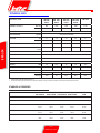 6
6
-
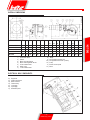 7
7
-
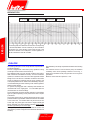 8
8
-
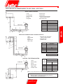 9
9
-
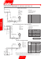 10
10
-
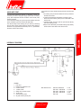 11
11
-
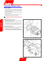 12
12
-
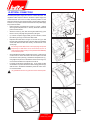 13
13
-
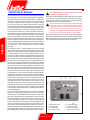 14
14
-
 15
15
-
 16
16
-
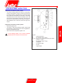 17
17
-
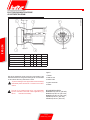 18
18
-
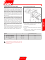 19
19
-
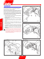 20
20
-
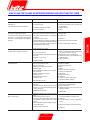 21
21
-
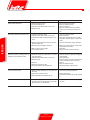 22
22
-
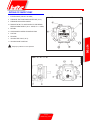 23
23
-
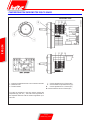 24
24
-
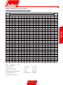 25
25
-
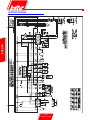 26
26
-
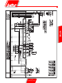 27
27
-
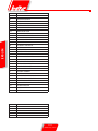 28
28
-
 29
29
-
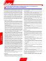 30
30
-
 31
31
-
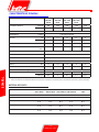 32
32
-
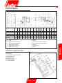 33
33
-
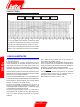 34
34
-
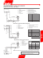 35
35
-
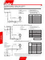 36
36
-
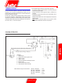 37
37
-
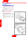 38
38
-
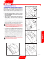 39
39
-
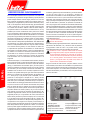 40
40
-
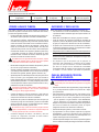 41
41
-
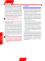 42
42
-
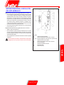 43
43
-
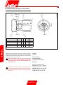 44
44
-
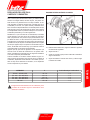 45
45
-
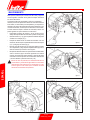 46
46
-
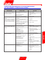 47
47
-
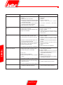 48
48
-
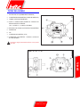 49
49
-
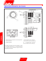 50
50
-
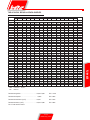 51
51
-
 52
52
-
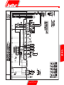 53
53
-
 54
54
-
 55
55
-
 56
56
-
 57
57
-
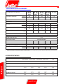 58
58
-
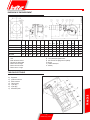 59
59
-
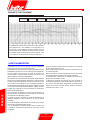 60
60
-
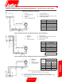 61
61
-
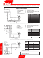 62
62
-
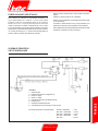 63
63
-
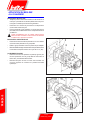 64
64
-
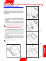 65
65
-
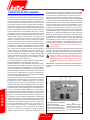 66
66
-
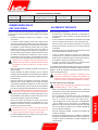 67
67
-
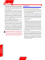 68
68
-
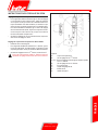 69
69
-
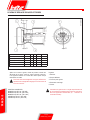 70
70
-
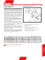 71
71
-
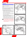 72
72
-
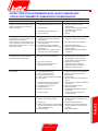 73
73
-
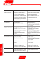 74
74
-
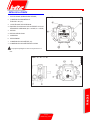 75
75
-
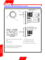 76
76
-
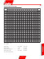 77
77
-
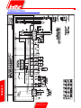 78
78
-
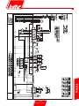 79
79
-
 80
80
-
 81
81
-
 82
82
-
 83
83
-
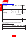 84
84
-
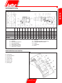 85
85
-
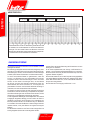 86
86
-
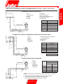 87
87
-
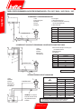 88
88
-
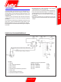 89
89
-
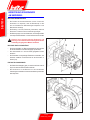 90
90
-
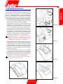 91
91
-
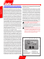 92
92
-
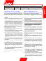 93
93
-
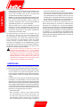 94
94
-
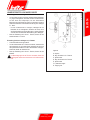 95
95
-
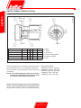 96
96
-
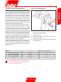 97
97
-
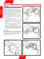 98
98
-
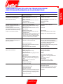 99
99
-
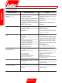 100
100
-
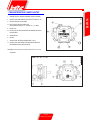 101
101
-
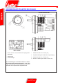 102
102
-
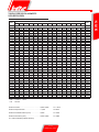 103
103
-
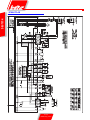 104
104
-
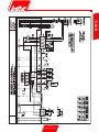 105
105
-
 106
106
-
 107
107
-
 108
108


BALTUR TBL 105P Manual User Instructions
- Categoría
- Chimeneas
- Tipo
- Manual User Instructions
- Este manual también es adecuado para
en otros idiomas
- français: BALTUR TBL 105P
- English: BALTUR TBL 105P
- Deutsch: BALTUR TBL 105P
Artículos relacionados
-
BALTUR TBL 130 P DACA 50Hz Use and Maintenance Manual
-
BALTUR TBML 800 ME 50Hz Use and Maintenance Manual
-
-
-
-
-
-
-
-
Otros documentos
-
Riello BG6.1D 1/230/50 Installer Manual
-
Riello G5R El manual del propietario
-
Atlantic SUNASANIT 3023 I 01 El manual del propietario
-
-
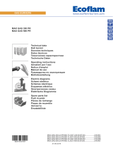 ECOFLAM MAX GAS 500 PR Operating Instructions Manual
-
Bernard Controls FQ Range Installation & Operation Manual
-
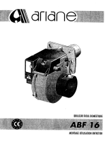 ARIANE ABF 16 El manual del propietario
-
-
Suntec Wellness KLIMATRONIC Heat Prime Manual de usuario
-
Bernard Controls AQ Range AQL Startup Manual

