
-1-
Documentazione
Tecnica
S18
rev. 1.1
02/2001
©
CAME
CANCELLI
AUTOMATICI
319S18
SCHEDA COMANDO
CONTROL BOARD
CARTE DE COMMANDE
STEUERPLATINE
TARJETA DE MANDO
SERIE Z |
Z SERIES
/ SÉRIE Z |
BAUREIHE Z |
SERIE Z
ZBX6
CANCELLI AUTOMATICI
CARATTERISTICHE GENERALI
ITALIANO
F U S I B IL I L I N E A 5 A
FU S. A C C ESSO RI 1A
T.C .A.
A F43S /S M
Descrizione
La scheda comando ZBX6 è adatta al
comando di automazioni scorrevoli
alimentati a 230V monofase della serie
BX-A/BX-B.
La scheda va inserita e fissata nel
contenitore porta-schede del moto-
riduttore (vedi descrizione di montaggio a
pag.6), ed alimentata con una tensione di
230V (a.c.) nei morsetti L1 e L2.
É protetta in ingresso con due fusibili da
5A, mentre i dispositivi di comando a
bassa tensione (24V) sono protetti con
fusibile da 1A.
La potenza complessiva degli accessori
(24V) non deve superare i 20W.
Il tempo lavoro è fisso a 80 secondi.
Sicurezza
Le fotocellule possono essere collegate e
predisposte per:
-
Riapertura
in fase di chiusura (2-C1), le
fotocellule rilevando un ostacolo durante
la fase di chiusura del
cancello, provocano
l'inversione di marcia fino
alla completa apertura;
-
Stop totale
(1-2), arresto
del cancello con l'esclu-
sione del ciclo di chiusura
automatica, per riprendere il movimento
del cancello, agire sulla pulsantiera o sul
radiocomando;
Altre funzioni
-
Chiusura automatica.
Il temporizzatore
di chiusura automatica si autoalimenta a
finecorsa in apertura. Il tempo prefissato
regolabile, è in ogni modo subordinato
dall'intervento di eventuali accessori di
sicurezza e si esclude dopo un intervento
di "stop" o in mancanza d'energia elettri-
ca;
-
"Uomo presente"
. Funzionamento del
cancello mantenendo premuto il pulsante
(esclude la funzione del radiocomando);
Regolazioni
- Tempo chiusura automatica;
Attenzione: prima di intervenire all’inter-
no dell’apparecchiatura, togliere la
tensione di linea.

-2-
GENERAL CHARACTERISTICS
ENGLISH
Description
The ZBX6 control board is used as a
remote control for BX-A/BX-B series
230V single-phase automated sliding
gates.
The board is introduced and fixed in
place in the gearmotor's circuit board
holder (see assembly description on
page 6), at 230V (a.c.) in terminals L1
and L2.
The inlet is protected with two 5A
fuses, while the low voltage (24V)
control devices are protected with a 1A
fuse.
The accessorie's total capacity (24V)
should not exceed 20W.
Fixed operating time of 80 seconds.
Safety
Photocells can be connected to abtain:
-
Re-opening
during closure (2-C1), if
the photocells identify an obstacle
while the gate is closing, they will
reverse the direction of movement until
the gate is completely open;
-
Total stop
(1-2), shutdown of gate
movement without automatic closing, a
pushbutton or radio remote control
must be actuated to resume
movement.
Other functions
-
Automatic closing.
The automatic
closing timer is automatically activated
at the end of the opening cycle. The
preset, adjustable automatic closing
time is automatically interrupted by the
activation of any safety system, and is
deactivated after a STOP command or
in case of power failure;
-
"Operator present"
. Gate operates
only when the pushbutton is held down
(the radio remote control system is
deactivated);
Adjiustments
- Automatic closure time;
IMPORTANT: Disconnect the unit from
the main power lines before carrying
out any operation inside the unit.

-3-
CARACTÉRISTIQUES GÉNÉRALES
FRANÇAIS
Description
La carte de commande ZBX6 est
indiquée pour commander les
automatismes coulissants alimentés à
230V et monophasés de la série BX-A/
BX-B.
Introduire la carte et la fixer dans le
porte-cartes du motoréducteur (voir
description du montage à la page 6).
La carte est alimentée avec une
tension de 230V (c.a.) dans les bornes
L1 et L2.
Elle est protégée à l'entrée par deux
fusibles de 5A, tandis que les
dispositifs de commande à basse
tension (24V) sont protégés par un
fusible de 1A.
La puissance totale des accessoires
(24V) ne doit pas dépasser 20W.
Temps de fonctionnement fixe de 80
sec.
Sécurité
Il est possible de brancher des
photocellules et de les programmer
pour:
-
Réouverture
en phase de fermeture
(2-C1), les cellules photoélectriques
provoquent l'inversion de marche
jusqu'à l'ouverture complète si elles
relèvent un obstacle durant la phase de
fermeture du portail;
-
Stop total
(1-2), arrêt du portail et
désactivation d’un éventuel cycle de
fermeture automatique; pour activer de
nouveau le mouvement, il faut agir sur
les boutons-poussoirs ou sur la
radiocommande.
Autres fonctions
-
Fermeture automatique.
Le tempo-
risateur de fermeture automatique est
autoalimenté à la fin du temps de la
course en ouverture. Le temps réglable
est programmé, cependant, il est
subordonné à l’intervention d’éventuels
accessoires de sécurité et il est exclu
après une intervention de “stop” ou en
cas de coupure de courant;
-
Fonction “homme mort”
. Fonc-
tionnement du portail en maintenant
appuyé le bouton-poussoir (exclut la
fonction de la radiocommande);
Réglages
- Temps de fermeture automatique;
ATTENTION: avant d'intervenir à
l'intérieur de l'appareillage, couper la
tension de ligne.

-4-
Beschreibung
Die Steuerplatine ZBX6 eignet sich zur
Steuerung der Automatik von
Schiebetoren der Baureihe BX-A und
BX-B mit 230V Einphasenversorgung.
Die Karte wird in das Kartenhalter-
Gehäuse des Getriebemotors
eingesetzt und dort befestigt (siehe
Montageanleitung auf S.6) und mit
einer Spannung von 230V (WS) über
die Klemmen L1 und L2 gespeist.
Die Karte ist am Eingang mit 2 5A-
Sicherungen geschützt, die Nieder-
spannungs-Steuervorrichtungen (24V)
dagegen sind mit einer 1A-Sicherung
geschützt.
Die Gesamtleistung der Zubehörteile
(24V) darf 20W nicht übersteigen.
Feste Laufzeit von 80 Sekunden.
Sicherheitsvorrichtungen
Die Lichtschranken können für
folgende Funktionen angeschlossen
bzw. vorbereitet werden:
-
Wiederöffnen
beim Schließen (2-C1),
die Lichtschranken ermitteln ein
Hindernis während des schließens
vom Tor und lösen die Umkehr der
Laufrichtung vom Tor aus, bis dieses
wieder vollständig geöffnet ist;
-
Totalstop
(1-2), sofortiger Stillstand
des Tores mit Ausschluß eventueller
Schließautomatik: Fortsetzung des
Torlaufs über Drucktaster- bzw. Funk-
sendersteuerung;
Andere Wahlfunktionen
-
Schließautomatik
. Der
Schließautomatik-Zeischalter speist
sich beim Öffnen am Ende der
Torlaufzeit selbst . Die voreingestellte
Zeit ist auf jeden Fall immer dem
Eingriff eventueller
Sicherheitsvorrichtungen
untergeordnet und schließt sich nach
einem “Stop”-Eingriff bzw. bei
Stromausfall selbst aus;
-
Funktion “Bedienung vom Steuerpult”
.
Torbetrieb durch Drucktasterbetätigung
(Funkfernsteuerung ausgeschlossen);
Einstellungen
- Zeit für das automatische Schließen;
ACHTUNG: Vor Eingriff im Innern des
Gerätes den Netzstecker ziehen.
ALLGEMEINE MERKMALE
DEUTSCH

-5-
Descripción cuadro de mando
La tarjeta de mando ZBX6 es idónea
para el accionamiento de automa-
tizaciones de puertas correderas
alimentadas a 230V monofásica de la
serie BX-A/BX-B.
La tarjeta se introduce y fija en la caja
respectiva en el motorreductor (véase
descripción montaje en pág.6), y se
alimenta con una tensión de 230V (c.a.)
en los bornes L1 y L2.
La tarjeta está protegida en la entrada
por dos fusibles de 5A, mientras que los
dispositivos de accionamiento de baja
tensión (24V) están protegidos por
fusible de 1A.
La potencia total de los accesorios
(24V) no tiene que superar los 20W.
Tiempo de trabajo fijo a 80 segundos.
Seguridad
Las fotocélulas pueden estar
conectadas y predispuestas para:
-
Reapertura
en la fase de cierre (2-
C1), las fotocélulas detectan un
obstáculo durante el cierre de la puerta,
provocando la inversión de marcha
hasta la apertura completa;
-
Parada total
(1-2), parada de la puerta
excluyendo el posible ciclo de cierre
automático; para reactivar el
movimiento es preciso actuar en el
teclado o en el mando a distancia);
Otras funciones
-
Cierre automático
. El temporizador de
cierre automático se autoalimenta en
fin-de-tiempo carrera en fase de aper-
tura. El tiempo prefijado regulable, sin
embargo, está subordinado a la
intervención de posibles accesorios de
seguridad y se excluye después de una
intervención de parada o en caso de
falta de energía eléctrica;
-
Función a "hombre presente"
. Fun-
cionamiento de la puerta manteniendo
pulsada la tecla (excluye la función del
mando a distancia).
Regulaciones
- Tiempo de cierre automático;
ATENCION: antes de actuar dentro del
aparado, quitar la tensión de línea.
CARACTERISTICAS GENERALES
ESPANOL

-6-
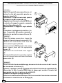
DESCRIZIONE DI MONTAGGIO -
ASSEMBLY DESCRIPTION
- DESCRIPTION DU MONTAGE
MONTAGEANLEITUNG -
DESCRIPTIÓN DEL MONTAJE
-Aprire lo sportello accesso sblocco, al-
lentare la vite del coperchio quadro co-
mando e levarlo (1).
-Rimuovere il copri-scheda dalla piastra
di supporto quadro comando (2).
-Agganciare e fissare la scheda ZBX6 nel-
la piastra di supporto quadro comando
con le viti predisposte (3).
-Riposizionare il supporto copri-schede
(4).
-Procedere al collegamento elettrico, fis-
sare il coperchio del quadro comando e
chiudere lo sportello accesso blocco (5).
-Open the release access door, loosen the
screws of the control panel cover and lift it (1).
-Remove the circuit board cover from the
control panel support plate (2).
-Hook and fix the ZBX6 board to the control
panel support plate with the appropriate
screws (3).
-Reposition the circuit board cover support
(4).
-Proceed with the electric connection, replace
the control panel cover and close the release
access door (5).
-Ouvrir le volet d'accès au déblocage, desserrer la vis du couvercle de l'armoire
de commande et l'enlever (1).
-Enlever le protège-carte de la plaque qui soutient l'armoire de commande (2).
-Accrocher et fixer la carte ZBX6 dans la plaque qui soutient l'armoire de
commande avec les vis prévues à cet effet (3).
-Remettre le support protège-cartes (4).
-Effectuer le branchement électrique, fixer le couvercle de l'armoire de commande
et refermer le volet d'accès au blocage (5).
ITALIANO
ENGLISH
FRANÇAIS
1
2

-7-
3
-Öffnen Sie die Klappe, die Zugriff auf die
Schalttafel gibt. Lösen Sie die Schrauben
von der Abdeckung der Schalttafel und
nehmen Sie die Abdeckung ab (1).
-Nehmen Sie die Kartenabdeckung von
der Halterungsplatte der Schalttafel ab
(2).
-Stecken Sie die Karte ZBX6 in die
Halterungsplatte der Schalttafel und
befestigen Sie die mit den entsprechenden
Schrauben (3).
-Bringen Sie die Kartenabdeckung wieder
an (4).
-Führen Sie den Stromanschluß durch.
Bringen Sie dann die Abdeckung wieder
auf der Schalttafel an und schließen Sie
die Klappe wieder (5).
-Abra la puerta de acceso al
desbloqueo, afloje el tornillo de la tapa
del cuadro de mando y quítelo (1).
-Quite el cubretarjeta de la placa de
soporte del cuadro de mando (2).
-Enganche y fije la tarjeta ZBX6 a la
placa de soporte del cuadro de mando,
con los tornillos suministrados (3).
-Vuelva a colocar el soporte
cubretaryeta (4).
-Realice la conexión eléctrica, fije la
tapa del cuadro de mando y cierre la
puerta de acceso al desbloqueo (5).
4
5
ESPANOL
DEUTSCH

-8-
SCHEDA BASE -
MOTHERBOARD
- CARTE BASE -
GRUNDPLATINE
- TARJETA BASE
F U S I B I L I L I N E A 5 A
FU S. AC C ESSO RI 1A
T.C .A .
A F43S /S M
1
2
3
4
5
6
8
7
9
9
COMPONENTI PRINCIPALI
1 Morsettiere di collegamento
2 Fusibili di linea 5A
3 Fusibile accessori 1A
4 Pulsante memorizzazione codice radio
5 Trimmer di regolazione tempo di chiusura automatica
6 Selettore funzioni a 2 dip (vedi pag.10)
7 Innesto scheda radiofrequenza (vedi tabella)
8 LED segnalazione
9 Asolature per fissaggio scheda
ITALIANO

-9-
HAUPTKOMPONENTEN
1 AnschlußKlemmenleiste
2 Hauptsicherung 5A
3 Zubehör-Sicherung 1A
4 Knöpfe zum Abspeicher der Radiocodes
5 Trimmer zur Einstellung Schließautomatik
6 Wählschalter für Funktionen mit 2 Dip (sehen S.10)
7 Steckanschluß Funkfrequenze-Platine AF (sehen Tabelle)
8 LED Kontrolleuchte zur Anzeige
9 Lochung für die Befestigung der Karte
PRINCIPALES COMPONENTES
1 Caja de bornes para las conexiónes
2 Fusibles de línea 5A
3 Fusible accesorios 1A
4 Teclas de memorización del código radio
5 Trimmer de regulación tiempo cierre automático
6 Selector de funciones con 2 dip (vedas pag.10)
7 Conexión tarjeta radiofrecuencia AF (vedas tabla)
8 LED de señal
9 Perforaciones para fijación de la tarjeta
MAIN COMPONENTES
1 Terminal block for external conections
2 Line fuses, 5A
3 Fuse on accessory power line, 1A
4 Radio-code save buttons
5 Trimmer for adjustment automatic closing
6 2-dip function switch (see pag.10)
7 Socket AF radiofrequency board (see table)
8 Signal LED
9 Grooves for board positioning
PRINCIPAUX COMPOSANTS
1 Plaque à bornes de connexion
2 Fusibles de ligne 5A
3 Fusible accessoires 1A
4 Boutons-poussoir mémorisation code radio
5 Trimmer de réglage fermeture automatique
6 Selecteur de fonctions à 2 interrupteurs à positions multiples (voir pag.10)
7 Branchement carte radiofréquence AF (voir tableau)
8 LED de signalisation
9 Fentes pour fixer la carte
ENGLISH
FRANÇAIS
ESPANOL
DEUTSCH

-10-
FUSIBILI LINEA 5A
FUS. ACCESSORI I 1A
T.C.A.
1 2
AF4 3S/SM
L1 L2 U V W E1
1112 7C110
FA FC F
1 OFF "Uomo presente" (esclude il fun-
zionamento del radiocomando)
disattivato; (1ON - attivato)
2 ON Chiusura automatica attivata;
(2OFF - disattivata)
REGOLAZIONI -
ADJUSTMENTS
- RÉGLAGES -
EINSTELLUNGEN
- REGULACIONES
Trimmer T.C.A.
= Regolazione tempo di
chiusura automatica da un minimo di 3
secondi a un massimo di 140 secondi.
SELEZIONI FUNZIONI -
SELECTION OF FUNCTIONS
- SÉLECTION FONCTIONS
FUNKTIONSWAHL
- SELECCIÓN DE LAS FUNCIONES
1 OFF "Operator present" (radio remote
control is deactivated when
function is selected) disabled;
(1ON - enabled)
2 ON Automatic closing enabled;
(2OFF - disabled)
1 OFF "Homme mort" (exclut la fonction
radiocommande) désactivèe;
(1ON-activée)
2 ON Fermeture automatique activée;
(2OFF - désactiée)
1 OFF Bedienung vom "Steuerpul" (bei
Wahl dieser Betriebsart wird die
Funkfernsteuerung ausgesch.)
deaktiviert; (1ON - aktiviert)
2 ON Schließautomatik aktiviert;
(2OFF - deaktiviert)
1 OFF "Hombre presente" (escluye la
función del mando de radio)
desactivado; (1ON - activado)
2 ON Cierre automático activado;
(2OFF - desactivado)
Trimmer T.C.A.
= Adjusts automatic
closing time from a minimum of 3 seconds
to a maximum of 140 seconds.
Trimmer T.C.A.
= Timer, auf dem die
Verzögerung für das automatische
Schlißen mit mindestens 3 Sekunden
und höchstens 140 Sekunden eingestellt
werden kann.
Trimmer T.C.A.
= Réglage du temps de
fermeture automatique d'un minimum de
3 secondes à un maximun de 140
secondes.
Trimmer T.C.A.
= Réglage du temps de
fermeture automatique d'un minimum de
3 secondes à un maximun de 140
secondes.
ON
OFF
FUSIBILI LINEA 5A
FUS. ACCESSORI I 1A
T.C.A.
1 2
AF4 3S/SM
L1 L2 U V W E1
1112 7C110
FA FC F
REGULACIÓN TRIMMERS
EINTELLUNG TRIMMERS
RÉGLAGE TRIMMERS
TRIMMERS ADJUSTMENT
REGOLAZIONE TRIMMERS
T.C .A .
ENGLISH FRANÇAIS
ESPANOL
ITALIANO
DEUTSCH
ENGLISH FRANÇAIS
ESPANOL
ITALIANO
DEUTSCH

-11-
Gruppo motore-finecorsa già collegati per montaggio a sinistra vista interna.
Per eventuale montaggio a destra:
- invertire FA-FC dei finecorsa sulla morsettiera;
- invertire le fasi U-V del motore sulla morsettiera.
The motor and limit switch unit are wired at the factory for mounting on the left-
hand side of the gate (as seen from the inside). If right-hand installation is desired:
- invert limit switch connections FA-FC on the terminal block;
- invert motor phase connections U-V on the terminal block.
Groupe moteur-fins de course déjà branchés pour le montage à gauche -
vue de l'intérieur.
Pour un éventuel montage à droite:
- inverser FA-FC des fins de course sur la plaque à bornes;
- inverser les phases U-V du moteur sur la plaque à bornes.
Das Motor-Anschlag-Aggregat schon für die Montage auf der linken Seite
angeschlossen, interne Ansicht.
Für eine eventuelle Montage auf der rechten Seite:
- die Öffnungs- und Schließungsphasen auf dem Klemmbrett invertieren;
- die U-V Phasen des Motors auf dem Klemmen tauschen.
Grupo motor-fin de carrera ya conectados para el montaje a la izquierda
vista interior.
Para el eventual montaje a la derecha:
- invertir FA-FC de los fines de carrera en el cuadro de bornes;
- invertir las fases U-V del motor en el cuadro de bornes.
COLLEGAMENTO FINECORSA -
LIMIT SWITCH CONNECTIONS
- BRANCHEMENT DE COURSE
ENDAUSSCHALTER-ANSCHLUSS
- CONEXION FINAL DE CARRERA
Gruppo finecorsa
Limit switch unit
Groupe fins de course
Anschlag-Gruppe
Grupo fin de carrera
Motore monofase 230V
230V single-phase motor
Moteur monophasé 230V
Einphasiger Motor 230V
Motor monofásico de 230V
Motore monofase 230V
230V single-phase motor
Moteur monophasé 230V
Einphasiger Motor 230V
Motor monofásico de 230V
Gruppo finecorsa
Limit switch unit
Groupe fins de course
Anschlag-Gruppe
Grupo fin de carrera
NC
NC
U W V
COM
FCFA F
M
NC
NC
U W V
F
CFA F
M
COM
ENGLISH
FRANÇAIS
ESPANOL
ITALIANO
DEUTSCH

-12-
COLLEGAMENTI ELETTRICI -
ELECTRICAL CONNECTIONS -
BRANCHEMENTS ÉLECTRIQUES
ELEKRISCHE ANSCHLÜSSE -
CONEXIONES ELÉCTRICAS
W
E1
U
W
V
L1
L2
10
11
Alimentazione 230V (a.c.)
230V (a.c.) power input
Alimentation 230V (c.a.)
Stromversorgung 230V (Wechselstrom)
Alimentación 230V (a.c.)
Motore monofase 230V (a.c.)
230V (a.c.) single-phase motor
Moteur monophasé 230V (c.a.)
Einphasenmotor 230V (Wechselstrom)
Motor monofásico 230V (a.c.)
Uscita 230V (a.c.) in movimento
(es.lampeggiatore - max. 25W)
230V (a.c.) output in motion
(e.g. flashing light - max. 25W)
Sortie 230V (c.a.) en mouvement
(ex. branchement clignotant - max. 25W)
Ausgang 230V (Wechselstrom) in Bewegung
(z.B. Blinker-Anschluß - max. 25W)
Salida de 230V (a.c.) en movimento
(p.ej. conexión lámpara intermitente - max. 25W)
Alimentazione accessori 24V (a.c.) max. 20W
24V (a.c.)Powering accessories (max 20W)
Alimentation accessoires 24V (c.a.) max. 20W
Zubehörspeisung 24V (Wechselstrom) max. 20W
Alimentación accesoios 24V (a.c.) max. 20W
Lampada spia (24V-3W max.) "cancello aperto"
(24V-3W max.) "gate-opened" signal lamp
Lampe-témoin (24V-3W max.) "portail ouverture"
Signallampe (24V-3W max.) "Tor Öffnen"
Lámpara indicadora (24V-3W max.) "puerta abierta"
11
FC
L1 L2 U V W E1
11 1 2 7 C110
FA FC F

-13-
11
FA
2
7
Lampada spia (24V-3W max.) "cancello chiuso"
(24V-3W max.) "gate-closed" signal lamp
Lampe-témoin (24V-3W max.) "portail fermeture"
Signallampe (24V-3W max.) "Tor Schließen"
Lámpara indicadora (24V-3W max.) "puerta cierre"
Pulsante stop (N.C.)
Pushbutton stop (N.C.)
Bouton-poussoir arrêt (N.F.)
Stop-Taste (N.C.)
Pulsador de stop (N.C.)
Contatto radio e/o pulsante per comando
Contact radio and/or button for control
Contact radio et/ou poussoir pour commande
Funkkontakt und/oder Taste Steuerart
Contacto radio y/o pulsador para mando
Contatto (N.C.) di «riapertura durante la chiusura»
Contact (N.C.) for «re-opening during the closing»
Contact (N.F.) de «réouverture pendant la fermeture»
Kontakt (Ruhekontakt) «Wiederöffnen beim Schliessen»
Contacto (N.C.) para la «apertura en la fase de cierre»
Collegamento finecorsa apre (vedi pag.11)
Connection limit switch opens (see pag.11)
Connexion fin de course ouverture (voir pag.11)
Anschluß Endschallter Öffnung (siehe S.11)
Conexión fin de carrera apertura (véase pàg.11)
Collegamento finecorsa chiude (vedi pag.11)
Connection limit switch closes (see pag.11)
Connexion fin de course fermeture (voir pag.11)
Anschluß Endschallter Schließung (siehe S.11)
Conexión fin de carrera cierre (véase pàg.11)
Collegamento antenna
Antenna connection
Connexion antenne
Antennenanschluß
Conexión antena
2
C1
F
FA
1
2
F
FC

-14-
PARA UTILIZAR EL MANDO A DISTANCIA ES PRE-
CISO:
1) Cortar la tensión al cuadro;
2) Si usa la tarjeta radiofrecuencia AF43S,
coloque el jumper de acuerdo con el tipo
de transmisor (fig.1), mientras que en la
tarjeta
AF43SM, siga las instrucciones en la hoja
correspondiente;
3) Introduzca la tarjeta radiofrecuencia
"AF" en el conector (fig.2);
LIMITATORE DI COPPIA MOTORE /
MOTOR TORQUE LIMITER
/ LIMITEUR DE COUPLE MOTEUR
DREHMOMENTBEGRENZER DES MOTORS
/ LIMITADOR DE PAR MOTOR
Per variare la coppia motrice, spostare il
faston indicato (con filo di colore nero) su
una delle 4 posizioni; 1 min. - 4 max
To vary the motor torque, move the
indicated faston to one of the four positions:
1=min, 4=max
Pour varier le couple du moteur, déplacer
le connecteur indiqué sur l'une des 4
positions; 1 min. - 4 max.
Zur Änderung des Motor-Drehmoments
den angegebenen Faston auf eine der 4
Stellungen positionieren: 1 min. - 4 max.
Para variar el par motor, desplazar el
faston indicado hasta una de las 4
posiciones; 1 mín. - 4 máx.
1
2 3 4
L2T
L1T
0
24
12
FUS. ACCESSORI 1A
L1T
01224
L2T C T
4) Codifique el transmisor (véase la hoja
de instrucciones correspondiente);
5) Conecte el cuadro;
6) Memorice la codificación en la tarjeta
de la siguiente manera:
a) mantenga apretada la tecla "CH1" en la
tarjeta base (el indicador luminoso de
señal parpadea);
b) con la tecla del transmisor se envía el
código, el indicador luminoso permanece
encendido para indicar que la
memorización se ha llevado a cabo (fig.3).
N.B.: si luego desea cambiar el código,
repita la secuencia descripta.
ENGLISH
FRANÇAIS
ESPANOL
ITALIANO
DEUTSCH
ESPANOL

-15-
B
A
COLLEGAMENTO PER 2 MOTORI ABBINATI -
CONNECTIONS FOR 2 COMBINED MOTORS
CONNEXIONS POUR 2 MOTEURS ACCOUPLÉS
ANSCHLUSSE FÜR 2 PARALLELGESCHALTETEN MOTOREN
- CONEXIÓN PARA 2 MOTORES ACOPLADOS
Nel caso d'installazione di due motori abbinati, procedere nel seguente modo:
- Coordinare il senso di marcia dei motoriduttori "A" e "B", modificando la
rotazione del motore "B" (vedi collegamento finecorsa);
- Su entrambi i quadri devono essere fatte le stesse regolazioni e funzioni (1);
- Eseguire i collegamenti elettrici tra le morsettiere del quadro "A" e "B" come
da «Fig. A»;
N.B. Nel caso di collegamento abbinato, non è previsto l'innesto della scheda
radiofrequenza, di conseguenza viene escluso l'utilizzo del radiocomando.
In case two combined motors are installed, proceed in the following manner:
- Coordinate the direction of the "A" and "B" gearmotors, modifying the rotation of
motor "B" (see limitswitch setting);
- The same settings and functions must be made on both control panels (1).
- Make the necessary electric connections between the terminal boards of the "A"
and "B" panels as in «Fig. A»;
N.B. In case of a paired connection, the coupling of the radio frequency board is not
provided for, so the use of the wireless control is excluded in this instance.
Pour installer deux moteurs accouplés, procéder comme suit:
- Coordonner le sens de marche des motoréducteurs "A" et "B" en modifiant
la rotation du moteur "B" (voir branchement interrupteur de fin de course);
- Les mêmes réglages et fonctions doivent être effectués sur les deux tableaux
(1).
- Effectuer les branchements électriques entre les plaques à borne du tableau
"A" et "B", comme indiqué sur la «Fig. A»;
N.B. En cas de branchement accouplé, la carte radiofréquence n'est pas prévue
et l'utilisation de la radiocommande est donc exclue.
ITALIANO
ENGLISH
FRANÇAIS

-16-
En el caso de instalación de dos motores combinados, actúe de la siguiente
manera:
-Coordine el sentido de marcha de los motorreductores "A" y "B", modifican-
do la rotación del motor «B» (véase conexión del final de carrera);
-Hay que realizar las mismas regulaciones y funciones en ambos cuadros (1);
-Realice las conexiones eléctricas entre los tableros de borne del cuadro "A"
y "B", como indicado en la «Fig. A»;
Nota. En el caso de conexión combinada, no está dispuesta la conexión de la
tarjeta de radiofrecuencia, por consiguiente se excluye el empleo del
radiocontrol.
Wenn zwei kombinierte Motoren installiert werden sollen, gehen Sie dazu bitte
folgendermaßen vor:
- Stimmen Sie die Laufrichtung der Getriebemotoren "A" und "B" aufeinander ab.
Andern Sie dazu die Drehrichtung vom Motor "B" (siehe endausschalter-anschluss);
- An beiden Schalttafeln müssen die gleichen Einstellungen erfolgen. Auch die
Funktionen müssen gleich sein (1);
-Führen Sie die elektrischen Anschlüsse zwischen den Klemmbretter von Schalttafel
"A" und "B" so durch, wie auf «Abb. A»
Hinweis. Bei kombiniertem Anschluß ist kein Einstecken der Radiofrequenzkarte
vorgesehen, d.h. daß die Verwendung von Fernbedienungen ausgeschlossen ist.
DEUTSCH
ESPANOL
FUSIBILI LINEA 5A
FUS. ACCESSORI I 1A
T.C.A.
1 2
AF 43S/ SM
L1 L2 U V W E1
1112 7C110
FA FC F
FUSIBILI LINEA 5A
FUS. ACCESSORI I 1A
T.C.A.
1 2
AF 43S/ SM
L1 L2 U V W E1
11 1 2 7 C110
FA FC F
FUNZIONI
FUNCTIONS
FONCTIONS
FUNKTIONEN
FUNCIONES
REGOLAZIONI
SETTING
RÉGLAGES
EINSTELLUNGEN
REGULACIONES
1

-17-
fig. A
Abb. A
10 11 1 2 7 C1
10 11 1 2 7 C1
(1-2)
(2-7)
(2-C 1)
Morsettiera del quadro
motore «A»
Terminal board of the "A" motor
control panel
Plaque à bornes du tableau du
moteur «A»
Klemmbrett der Schalttafel vom
Motor «A»
Tablero de bornes del cuadro
motor «A»
Morsettiera del quadro
motore «B»
Terminal board of the "B" motor
control panel
Plaque à bornes du tableau du
moteur «B»
Klemmbrett der Schalttafel vom
Motor «B»
Tablero de bornes del cuadro
motor «B»

-18-
ZA5
ENGLISH
PROCEDURE
A. insert an
AF card **.
B. encode
transmitter/s.
C. store code in
the
motherboard.
FRANÇAIS
PROCEDURE
A. placer une
carte AF **.
B. codifier le/s
émetteur/s.
C. mémoriser la
codification
sur la carte
base.
DEUTSCH
PROZEDUR
A. Stecken Sie
eine Karte
AF **.
B. Codieren Sie
den/die
Sender.
C. Speichern Sie
die Codierung
auf der
Grundplatine.
ITALIANO
PROCEDURA
A. inserire una
scheda AF **.
B. codificare il/i
trasmettitore/i.
C. memorizzare la
codifica sulla
scheda base.
INSTALLAZIONE DEL RADIOCOMANDO -
RADIO
CONTROL
INSTALLATION
-
INSTALLATION DE LA RADIOCOMMANDE
INSTALLATION
DER
RADIOSTEUERUNG
-
INSTALACIÓN DEL RADIOMANDO
ESPANOL
PROCEDIMIENTO
A. introducir
una tarjeta
AF **.
B. codificar el/
los
transmisor/
es.
C. memorizar la
codificación
en la tarjeta
base.
(**) Per trasmettitori con frequenza 433.92 AM (serie TOP e serie
TAM) bisogna, sulla relativa scheda AF43S, posizionare il jumper
come illustrato.
(**) On AM transmitters operating at 433.92 MHz (TOP and TAM
series), position the jumper connection on circuit card AF43S as
shown on the sheet.
(**) Pour les émetteurs de fréquence 433.92 AM (série TOP et
série TAM) il faut positionner le pontet sur la carte AF43S
correspondante de la façon indiquée.
(**) Bei Sendern mit einer Frequenz von 433.92 AM (Reihe TOP und
Reihe TAM) ist der auf der entsprechenden Platine AF43S befindliche
Jumper der Abbildung entsprechend zu positionieren.
(**) Para transmisores con frecuencia 433.92 AM (serie TOP y
serie TAM) es necesario, en la tarjeta corespondiente AF43S,
colocar el jumper como se indica
TOP
TAM
SCHEDA BASE
MOTHERBOARD
CARTE DE BASE
BASISKARTE
TARJETA BASE
SCHEDA "AF"
"AF" BOARD
CARTE "AF"
KARTE «AF»
TARJETA «AF»
La schedina AF deve essere inserita OBBLIGATORIAMENTE in assenza di tensione, perché la scheda madre la riconosce solo quando viene alimentata
The AF board should ALWAYS be inserted when the power is off because the motherboard only recognises it when it is powered.
La carte AF doit OBLIGATOIREMENT être branchée en l’absence de tension car la carte mère ne la reconnaît que quand elle est alimentée.
Vor Einschieben der Karte die Stromzufuhr UNBEDINGT abschalten, da die Erkennung durch die Hauptkarte nur über eine Neueinschaltung ( nur durch Versorgung) erfolgt.
La tarjeta AF se debe montar OBLIGATORIAMENTE en caso de falta de corriente, porque la tarjeta madre la reconoce sólo cuando está alimentada
zHM/azneuqerF
zHM/ycneuqerF
zHM/ecneuqerF
zHM/zneuqerF
zHM/aicneucerF
azneuqerfoidaradehcS
draobycneuqerfoidaR
ecneuqérfoidaretraC
enitalP-zneuqerfknuF
aicneucerfoidaratejraT
erotittemsarT
rettimsnarT
ruettemE
rednesknuF
rosimsnarT
599.62MF 031FA MFT
009.03MF 051FA MFT
29.334MA
MS34FA/S34FA POT/MAT
RS34FA OMOTA
INSERIMENTO SCHEDA AF -
AF BOARD INSERTION
- NSTALLATION DE LA CARTE AF
EINSTECKEN DER KARTE AF /
MONTAJE DE LA TARJETA AF
A
A F43S /S M

-19-
AT01 - AT02
vedi foglio istruzioni inserito nella confezione
della scheda AF43SR
see instruction sheet inside the pack of AF43SR circuit card
voir les instructions qui se trouve dans l'emballage
de la carte AF43SR
Siehe Anleitungen, die der Packung beiliegen der Platine AF43SR
ver hoja de instrucciones adjunta en el embalaje
de la tarjeta AF43SR
ATOMO
CODIFICA TRASMETTITORI -
TRANSMITTER ENCODING
- CODIFICATION DES EMETTEURS
CODIERUNG DER SENDER
- CODIFICACIÓN TRANSMISORES
B
vedi istruzioni su confezione
see instructions on pack
voir instructions sur l'emballage
Siehe Anleitungen auf der Packung.
ver instrucciones en el embalaje
T432S / T432SA
T434M - T314M
impostare solo il codice
set code only
ne saisir que le code
Stellen Sie nur den Code ein.
plantear sólo el código
P1=CH1
P2=CH2
P3=CH3
P4=CH4
1 2 3 4 5 6 7 8 9 10
C
P1 P2
P3 P4
TOP
impostare il codice sul dip-switch C e il canale su D (P1=CH1 e P2=CH2,
impostazione di default)
set the code to dip-switch C and channel to D (P1=CH1 and P2=CH2, default
setting)
saisir le code sur le commutateur dip C et le canal sur D (P1=CH1 et P2=CH2,
saisie de défaut)
Stellen Sie den Code auf den Dip-Switch C und den Kanal auf D (P1=CH1
und P2=CH2; Grundeinstellung).
plantear el código en el dip-switch C y el canal en D (P1=CH1 y P2=CH2,
planteamiento por defecto)
T432M - T312M
1 2 3 4 5 6 7 8 9 10
1 2 3 4
C
D
P1 P2
P2
CH1 CH2 CH3
CH4
P1
CH1 CH2 CH3
CH4
1 2 3 4 1 2 3 4 1 2 3 41 2 3 4
1 2 3 4 1 2 3 4 1 2 3 4 1 2 3 4
vedi foglio istruzioni inserito nella
confezione
see instruction sheet inside the pack
voir la notice d'instructions qui se
trouve dans l'emballage
Siehe Anleitungen, die der Packung
beiliegen.
ver hoja de instrucciones adjunta en el
embalaje
TAM
T132
T134
T138
T152
T154
T158
T432
T434
T438
TFM

-20-
CAME LOMBARDIA S.R.L.___COLOGNO M. (MI)
(+39) 02 26708293 (+39) 02 25490288
CAME SUD S.R.L. _________________NAPOLI
(+39) 081 752445 (+39) 081 7529109
CAME (AMERICA) L.L.C._________MIAMI (FL)
(+1) 305 5930227 (+1) 305 5939823
CAME AUTOMATISMOS S.A_________MADRID
(+34) 091 5285009 (+34) 091 4685442
CAME BELGIUM____________LESSINES
(+32) 068 333014 (+32) 068 338019
CAME CANCELLI AUTOMATICI S.P.A.
DOSSON DI CASIER (TREVISO)
(+39) 0422 (+39) 0422 490944
CANCELLI AUTOMATICI
CAME FRANCE S.A.___NANTERRE CEDEX (PARIS)
(+33) 01 46130505 (+33) 01 46130500
CAME GMBH____KORNTAL BEI (STUTTGART)
(+49) 07 11839590 (+49) 07 118395925
CAME GMBH________SEEFELD BEI (BERLIN)
(+49) 03 33988390 (+49) 03 339885508
CAME PL SP.ZO.O_________WARSZAWA
(+48) 022 8699933 (+48) 022 6399933
CAME UNITED KINGDOM LTD___NOTTINGHAM
(+44) 01159 387200 (+44) 01159 382694
A
SSISTENZA TECNICA
NUMERO VERDE
800 295830
W
EB
www.came.it
E-
MAIL
SISTEMA QUALITÀ
CERTIFICATO
ITALIANO
-Tenere
premuto il
tasto "CH1"
sulla scheda
base (il led di
segnalazione
lampeggia),
con un tasto
del trasmettito-
re s'invia il
codice, il led
rimarrà acceso
a segnalare
l'avvenuta
memorizzazione
(vedi fig.1).
DEUTSCH
-Halten Sie die
Taste CH1 an
der Basiskarte
gedrückt (die
Kontrolleuchte
blinkt). Senden
Sie den Code
mit einer Taste
vom Sender.
Der
Kontrolleuchte
bleibt jetzt an
und zeigt
dadurch das
erfolgte
Speichern an
(Abb.1).
ESPANOL
-Mantener
oprimida la
tecla "CH1" en
la tarjeta base
(el led de
señalización
parpadea), con
una tecla del
transmisor se
envía el
código, el led
permanece
encendido
para indicar
que el
almacenamendo
se ha
efectuado
(fig.1).
ENGLISH
-Keep the CH1
key pressed on
the base card
(the signal LED
will flash), and
with a key on
the transmitter
the code is
sent, the LED
will remain lit to
signal the
successful
saving of the
code (figure 1).
FRANÇAIS
-Appuyer sur
la touche
"CH1" sur la
carte de base
(le led de
signalisation
clignote), avec
une touche du
emetteur on
envoie le code,
le led restera
allumé pour
signaler que la
mémorisation
s'est effectuèe
(fig.1).
MEMORIZZAZIONE CODICE -
CODE STORAGE
- MEMORISATION DU CODE
SPEICHERN VOM CODE
- MEMORIZACIÓN CÓDIGO
C
T.L.
T.C .A .
A F43S /S M
PROG
CH1
LED di segnalazione
signal LED
LED de signalisation
Anzeigeleuchtdiode
LED de señal
Scheda radiofrequenza AF
AF radiofrequency board
Carte radiofrèquence AF
Funkfrequenz-Platine AF
Tarjeta radiofrecuencia AF
T.L.
T.C .A .
A F43S /S M
PROG
CH1
FIG. 1FIG. 1
FIG. 1FIG. 1
FIG. 1
Transcripción de documentos
Z | Z SERIES / SÉRIE Z | Z | SERIE Z Documentazione Tecnica S18 SCHEDA COMANDO CONTROL BOARD CARTE DE COMMANDE STEUERPLATINE TARJETA DE MANDO rev. 1.1 02/2001 ZBX6 CANCELLI AUTOMATICI F U S IB IL I L IN E A 5 A BAUREIHE © CAME CANCELLI AUTOMATICI 319S18 F U S .A C C E S S O R I1 A A F 4 3 S /S M SERIE T .C .A . CARATTERISTICHE GENERALI ITALIANO Descrizione La scheda comando ZBX6 è adatta al comando di automazioni scorrevoli alimentati a 230V monofase della serie BX-A/BX-B. La scheda va inserita e fissata nel contenitore porta-schede del motoriduttore (vedi descrizione di montaggio a pag.6), ed alimentata con una tensione di 230V (a.c.) nei morsetti L1 e L2. É protetta in ingresso con due fusibili da 5A, mentre i dispositivi di comando a bassa tensione (24V) sono protetti con fusibile da 1A. La potenza complessiva degli accessori (24V) non deve superare i 20W. Il tempo lavoro è fisso a 80 secondi. Sicurezza automatica, per riprendere il movimento del cancello, agire sulla pulsantiera o sul radiocomando; Altre funzioni - Chiusura automatica. Il temporizzatore di chiusura automatica si autoalimenta a finecorsa in apertura. Il tempo prefissato regolabile, è in ogni modo subordinato dall'intervento di eventuali accessori di sicurezza e si esclude dopo un intervento di "stop" o in mancanza d'energia elettrica; - "Uomo presente". Funzionamento del cancello mantenendo premuto il pulsante (esclude la funzione del radiocomando); Regolazioni - Tempo chiusura automatica; Le fotocellule possono essere collegate e Attenzione: prima di intervenire all’interpredisposte per: - Riapertura in fase di chiusura (2-C1), le no dell’apparecchiatura, togliere la fotocellule rilevando un ostacolo durante tensione di linea. la fase di chiusura del cancello, provocano l'inversione di marcia fino alla completa apertura; - Stop totale (1-2), arresto del cancello con l'esclusione del ciclo di chiusura -1- GENERAL CHARACTERISTICS ENGLISH Description The ZBX6 control board is used as a remote control for BX-A/BX-B series 230V single-phase automated sliding gates. The board is introduced and fixed in place in the gearmotor's circuit board holder (see assembly description on page 6), at 230V (a.c.) in terminals L1 and L2. The inlet is protected with two 5A fuses, while the low voltage (24V) control devices are protected with a 1A fuse. The accessorie's total capacity (24V) should not exceed 20W. Fixed operating time of 80 seconds. Safety Photocells can be connected to abtain: - Re-opening during closure (2-C1), if the photocells identify an obstacle while the gate is closing, they will reverse the direction of movement until the gate is completely open; -2- - Total stop (1-2), shutdown of gate movement without automatic closing, a pushbutton or radio remote control must be actuated to resume movement. Other functions - Automatic closing. The automatic closing timer is automatically activated at the end of the opening cycle. The preset, adjustable automatic closing time is automatically interrupted by the activation of any safety system, and is deactivated after a STOP command or in case of power failure; - "Operator present". Gate operates only when the pushbutton is held down (the radio remote control system is deactivated); Adjiustments - Automatic closure time; IMPORTANT: Disconnect the unit from the main power lines before carrying out any operation inside the unit. FRANÇAIS CARACTÉRISTIQUES GÉNÉRALES Description La carte de commande ZBX6 est indiquée pour commander les automatismes coulissants alimentés à 230V et monophasés de la série BX-A/ BX-B. Introduire la carte et la fixer dans le porte-cartes du motoréducteur (voir description du montage à la page 6). La carte est alimentée avec une tension de 230V (c.a.) dans les bornes L1 et L2. Elle est protégée à l'entrée par deux fusibles de 5A, tandis que les dispositifs de commande à basse tension (24V) sont protégés par un fusible de 1A. La puissance totale des accessoires (24V) ne doit pas dépasser 20W. Temps de fonctionnement fixe de 80 sec. Sécurité Il est possible de brancher des photocellules et de les programmer pour: - Réouverture en phase de fermeture (2-C1), les cellules photoélectriques provoquent l'inversion de marche jusqu'à l'ouverture complète si elles relèvent un obstacle durant la phase de fermeture du portail; - Stop total (1-2), arrêt du portail et désactivation d’un éventuel cycle de fermeture automatique; pour activer de nouveau le mouvement, il faut agir sur les boutons-poussoirs ou sur la radiocommande. Autres fonctions - Fermeture automatique. Le temporisateur de fermeture automatique est autoalimenté à la fin du temps de la course en ouverture. Le temps réglable est programmé, cependant, il est subordonné à l’intervention d’éventuels accessoires de sécurité et il est exclu après une intervention de “stop” ou en cas de coupure de courant; - Fonction “homme mort”. Fonctionnement du portail en maintenant appuyé le bouton-poussoir (exclut la fonction de la radiocommande); Réglages - Temps de fermeture automatique; ATTENTION: avant d'intervenir à l'intérieur de l'appareillage, couper la tension de ligne. -3- ALLGEMEINE MERKMALE DEUTSCH Beschreibung Die Steuerplatine ZBX6 eignet sich zur Steuerung der Automatik von Schiebetoren der Baureihe BX-A und BX-B mit 230V Einphasenversorgung. Die Karte wird in das KartenhalterGehäuse des Getriebemotors eingesetzt und dort befestigt (siehe Montageanleitung auf S.6) und mit einer Spannung von 230V (WS) über die Klemmen L1 und L2 gespeist. Die Karte ist am Eingang mit 2 5ASicherungen geschützt, die Niederspannungs-Steuervorrichtungen (24V) dagegen sind mit einer 1A-Sicherung geschützt. Die Gesamtleistung der Zubehörteile (24V) darf 20W nicht übersteigen. Feste Laufzeit von 80 Sekunden. - Totalstop (1-2), sofortiger Stillstand des Tores mit Ausschluß eventueller Schließautomatik: Fortsetzung des Torlaufs über Drucktaster- bzw. Funksendersteuerung; Andere Wahlfunktionen - Schließautomatik. Der Schließautomatik-Zeischalter speist sich beim Öffnen am Ende der Torlaufzeit selbst . Die voreingestellte Zeit ist auf jeden Fall immer dem Eingriff eventueller Sicherheitsvorrichtungen untergeordnet und schließt sich nach einem “Stop”-Eingriff bzw. bei Stromausfall selbst aus; - Funktion “Bedienung vom Steuerpult”. Torbetrieb durch Drucktasterbetätigung (Funkfernsteuerung ausgeschlossen); Sicherheitsvorrichtungen Die Lichtschranken können für folgende Funktionen angeschlossen bzw. vorbereitet werden: - Wiederöffnen beim Schließen (2-C1), die Lichtschranken ermitteln ein Hindernis während des schließens vom Tor und lösen die Umkehr der Laufrichtung vom Tor aus, bis dieses wieder vollständig geöffnet ist; -4- Einstellungen - Zeit für das automatische Schließen; ACHTUNG: Vor Eingriff im Innern des Gerätes den Netzstecker ziehen. ESPANOL CARACTERISTICAS GENERALES Descripción cuadro de mando La tarjeta de mando ZBX6 es idónea para el accionamiento de automatizaciones de puertas correderas alimentadas a 230V monofásica de la serie BX-A/BX-B. La tarjeta se introduce y fija en la caja respectiva en el motorreductor (véase descripción montaje en pág.6), y se alimenta con una tensión de 230V (c.a.) en los bornes L1 y L2. La tarjeta está protegida en la entrada por dos fusibles de 5A, mientras que los dispositivos de accionamiento de baja tensión (24V) están protegidos por fusible de 1A. La potencia total de los accesorios (24V) no tiene que superar los 20W. Tiempo de trabajo fijo a 80 segundos. - Parada total (1-2), parada de la puerta excluyendo el posible ciclo de cierre automático; para reactivar el movimiento es preciso actuar en el teclado o en el mando a distancia); Otras funciones - Cierre automático. El temporizador de cierre automático se autoalimenta en fin-de-tiempo carrera en fase de apertura. El tiempo prefijado regulable, sin embargo, está subordinado a la intervención de posibles accesorios de seguridad y se excluye después de una intervención de parada o en caso de falta de energía eléctrica; - Función a "hombre presente". Funcionamiento de la puerta manteniendo pulsada la tecla (excluye la función del mando a distancia). Seguridad Regulaciones Las fotocélulas pueden estar conectadas y predispuestas para: - Tiempo de cierre automático; - Reapertura en la fase de cierre (2C1), las fotocélulas detectan un obstáculo durante el cierre de la puerta, ATENCION: antes de actuar dentro del provocando la inversión de marcha aparado, quitar la tensión de línea. hasta la apertura completa; -5- DESCRIZIONE DI MONTAGGIO - ASSEMBLY DESCRIPTION - DESCRIPTION DU MONTAGE MONTAGEANLEITUNG - DESCRIPTIÓN DEL MONTAJE ITALIANO -Aprire lo sportello accesso sblocco, allentare la vite del coperchio quadro comando e levarlo (1). -Rimuovere il copri-scheda dalla piastra di supporto quadro comando (2). -Agganciare e fissare la scheda ZBX6 nella piastra di supporto quadro comando con le viti predisposte (3). -Riposizionare il supporto copri-schede (4). -Procedere al collegamento elettrico, fissare il coperchio del quadro comando e chiudere lo sportello accesso blocco (5). 1 ENGLISH -Open the release access door, loosen the screws of the control panel cover and lift it (1). -Remove the circuit board cover from the control panel support plate (2). -Hook and fix the ZBX6 board to the control panel support plate with the appropriate screws (3). -Reposition the circuit board cover support (4). -Proceed with the electric connection, replace the control panel cover and close the release access door (5). 2 FRANÇAIS -Ouvrir le volet d'accès au déblocage, desserrer la vis du couvercle de l'armoire de commande et l'enlever (1). -Enlever le protège-carte de la plaque qui soutient l'armoire de commande (2). -Accrocher et fixer la carte ZBX6 dans la plaque qui soutient l'armoire de commande avec les vis prévues à cet effet (3). -Remettre le support protège-cartes (4). -Effectuer le branchement électrique, fixer le couvercle de l'armoire de commande et refermer le volet d'accès au blocage (5). -6- DEUTSCH -Öffnen Sie die Klappe, die Zugriff auf die Schalttafel gibt. Lösen Sie die Schrauben von der Abdeckung der Schalttafel und nehmen Sie die Abdeckung ab (1). -Nehmen Sie die Kartenabdeckung von der Halterungsplatte der Schalttafel ab (2). -Stecken Sie die Karte ZBX6 in die Halterungsplatte der Schalttafel und befestigen Sie die mit den entsprechenden Schrauben (3). -Bringen Sie die Kartenabdeckung wieder an (4). -Führen Sie den Stromanschluß durch. Bringen Sie dann die Abdeckung wieder auf der Schalttafel an und schließen Sie die Klappe wieder (5). 3 4 ESPANOL -Abra la puerta de acceso al desbloqueo, afloje el tornillo de la tapa del cuadro de mando y quítelo (1). -Quite el cubretarjeta de la placa de soporte del cuadro de mando (2). -Enganche y fije la tarjeta ZBX6 a la placa de soporte del cuadro de mando, con los tornillos suministrados (3). -Vuelva a colocar el soporte cubretaryeta (4). -Realice la conexión eléctrica, fije la tapa del cuadro de mando y cierre la puerta de acceso al desbloqueo (5). 5 -7- SCHEDA BASE - MOTHERBOARD - CARTE BASE - GRUNDPLATINE - TARJETA BASE 1 F U S IB IL I L IN E A 5 A F U S .A C C E S S O R I1 A 9 9 2 A F 4 3 S /S M 5 T .C .A . 3 4 6 ITALIANO 1 2 3 4 5 6 7 8 9 -8- 8 COMPONENTI PRINCIPALI Morsettiere di collegamento Fusibili di linea 5A Fusibile accessori 1A Pulsante memorizzazione codice radio Trimmer di regolazione tempo di chiusura automatica Selettore funzioni a 2 dip (vedi pag.10) Innesto scheda radiofrequenza (vedi tabella) LED segnalazione Asolature per fissaggio scheda 7 ENGLISH 1 2 3 4 5 6 7 8 9 Terminal block for external conections Line fuses, 5A Fuse on accessory power line, 1A Radio-code save buttons Trimmer for adjustment automatic closing 2-dip function switch (see pag.10) Socket AF radiofrequency board (see table) Signal LED Grooves for board positioning FRANÇAIS 1 2 3 4 5 6 7 8 9 HAUPTKOMPONENTEN AnschlußKlemmenleiste Hauptsicherung 5A Zubehör-Sicherung 1A Knöpfe zum Abspeicher der Radiocodes Trimmer zur Einstellung Schließautomatik Wählschalter für Funktionen mit 2 Dip (sehen S.10) Steckanschluß Funkfrequenze-Platine AF (sehen Tabelle) LED Kontrolleuchte zur Anzeige Lochung für die Befestigung der Karte ESPANOL 1 2 3 4 5 6 7 8 9 PRINCIPAUX COMPOSANTS Plaque à bornes de connexion Fusibles de ligne 5A Fusible accessoires 1A Boutons-poussoir mémorisation code radio Trimmer de réglage fermeture automatique Selecteur de fonctions à 2 interrupteurs à positions multiples (voir pag.10) Branchement carte radiofréquence AF (voir tableau) LED de signalisation Fentes pour fixer la carte DEUTSCH 1 2 3 4 5 6 7 8 9 MAIN COMPONENTES PRINCIPALES COMPONENTES Caja de bornes para las conexiónes Fusibles de línea 5A Fusible accesorios 1A Teclas de memorización del código radio Trimmer de regulación tiempo cierre automático Selector de funciones con 2 dip (vedas pag.10) Conexión tarjeta radiofrecuencia AF (vedas tabla) LED de señal Perforaciones para fijación de la tarjeta -9- SELEZIONI FUNZIONI - SELECTION OF FUNCTIONS - SÉLECTION FONCTIONS FUNKTIONSWAHL- SELECCIÓN DE LAS FUNCIONES ITALIANO U V W E1 10 11 1 2 7 C1 FA FC F FUS. ACCE SSORII1A T.C .A. AF43S/SM L1 L2 FUSIBILI LINEA5A 1 2 ON OFF ENGLISH 1 OFF "Uomo presente" (esclude il funzionamento del radiocomando) disattivato; (1ON - attivato) 2 ON Chiusura automatica attivata; (2OFF - disattivata) FRANÇAIS 1 OFF "Operator present" (radio remote control is deactivated when function is selected) disabled; (1ON - enabled) 2 ON Automatic closing enabled; (2OFF - disabled) 1 OFF "Homme mort" (exclut la fonction radiocommande) désactivèe; (1ON-activée) 2 ON Fermeture automatique activée; (2OFF - désactiée) ESPANOL DEUTSCH 1 OFF Bedienung vom "Steuerpul" (bei Wahl dieser Betriebsart wird die Funkfernsteuerung ausgesch.) deaktiviert; (1ON - aktiviert) 2 ON Schließautomatik aktiviert; (2OFF - deaktiviert) 1 OFF "Hombre presente" (escluye la función del mando de radio) desactivado; (1ON - activado) 2 ON Cierre automático activado; (2OFF - desactivado) REGOLAZIONI - ADJUSTMENTS - RÉGLAGES - EINSTELLUNGEN - REGULACIONES U V W E1 10 11 1 2 7 C1 FA FC F T .C .A . FUS. ACCE SSORII1A T.C .A. AF43S/SM L1 L2 FUSIBILI LINEA5A 1 2 REGOLAZIONE TRIMMERS TRIMMERS ADJUSTMENT RÉGLAGE TRIMMERS EINTELLUNG TRIMMERS REGULACIÓN TRIMMERS ENGLISH Trimmer T.C.A. = Adjusts automatic closing time from a minimum of 3 seconds to a maximum of 140 seconds. DEUTSCH Trimmer T.C.A. = Timer, auf dem die Verzögerung für das automatische Schlißen mit mindestens 3 Sekunden und höchstens 140 Sekunden eingestellt werden kann. -10- ITALIANO Trimmer T.C.A. = Regolazione tempo di chiusura automatica da un minimo di 3 secondi a un massimo di 140 secondi. FRANÇAIS Trimmer T.C.A. = Réglage du temps de fermeture automatique d'un minimum de 3 secondes à un maximun de 140 secondes. ESPANOL Trimmer T.C.A. = Réglage du temps de fermeture automatique d'un minimum de 3 secondes à un maximun de 140 secondes. COLLEGAMENTO FINECORSA - LIMIT SWITCH CONNECTIONS - BRANCHEMENT DE COURSE ENDAUSSCHALTER-ANSCHLUSS - CONEXION FINAL DE CARRERA ITALIANO Gruppo motore-finecorsa già collegati per montaggio a sinistra vista interna. Per eventuale montaggio a destra: - invertire FA-FC dei finecorsa sulla morsettiera; - invertire le fasi U-V del motore sulla morsettiera. ENGLISH The motor and limit switch unit are wired at the factory for mounting on the lefthand side of the gate (as seen from the inside). If right-hand installation is desired: - invert limit switch connections FA-FC on the terminal block; - invert motor phase connections U-V on the terminal block. FRANÇAIS Groupe moteur-fins de course déjà branchés pour le montage à gauche vue de l'intérieur. Pour un éventuel montage à droite: - inverser FA-FC des fins de course sur la plaque à bornes; - inverser les phases U-V du moteur sur la plaque à bornes. DEUTSCH Das Motor-Anschlag-Aggregat schon für die Montage auf der linken Seite angeschlossen, interne Ansicht. Für eine eventuelle Montage auf der rechten Seite: - die Öffnungs- und Schließungsphasen auf dem Klemmbrett invertieren; - die U-V Phasen des Motors auf dem Klemmen tauschen. ESPANOL Grupo motor-fin de carrera ya conectados para el montaje a la izquierda vista interior. Para el eventual montaje a la derecha: - invertir FA-FC de los fines de carrera en el cuadro de bornes; - invertir las fases U-V del motor en el cuadro de bornes. NC NC F U W V COM FA FC NC FC NC FA F U W V COM M Gruppo finecorsa Limit switch unit Groupe fins de course Anschlag-Gruppe Grupo fin de carrera Motore monofase 230V 230V single-phase motor Moteur monophasé 230V Einphasiger Motor 230V Motor monofásico de 230V M Gruppo finecorsa Limit switch unit Groupe fins de course Anschlag-Gruppe Grupo fin de carrera Motore monofase 230V 230V single-phase motor Moteur monophasé 230V Einphasiger Motor 230V Motor monofásico de 230V -11- COLLEGAMENTI ELETTRICI - ELECTRICAL CONNECTIONS - BRANCHEMENTS ÉLECTRIQUES ELEKRISCHE ANSCHLÜSSE - CONEXIONES ELÉCTRICAS L1 L2 L1 L2 U W V W E1 10 11 11 FC -12- U V W E1 10 11 1 2 7 C1 FA FC F Alimentazione 230V (a.c.) 230V (a.c.) power input Alimentation 230V (c.a.) Stromversorgung 230V (Wechselstrom) Alimentación 230V (a.c.) Motore monofase 230V (a.c.) 230V (a.c.) single-phase motor Moteur monophasé 230V (c.a.) Einphasenmotor 230V (Wechselstrom) Motor monofásico 230V (a.c.) Uscita 230V (a.c.) in movimento (es.lampeggiatore - max. 25W) 230V (a.c.) output in motion (e.g. flashing light - max. 25W) Sortie 230V (c.a.) en mouvement (ex. branchement clignotant - max. 25W) Ausgang 230V (Wechselstrom) in Bewegung (z.B. Blinker-Anschluß - max. 25W) Salida de 230V (a.c.) en movimento (p.ej. conexión lámpara intermitente - max. 25W) Alimentazione accessori 24V (a.c.) max. 20W 24V (a.c.)Powering accessories (max 20W) Alimentation accessoires 24V (c.a.) max. 20W Zubehörspeisung 24V (Wechselstrom) max. 20W Alimentación accesoios 24V (a.c.) max. 20W Lampada spia (24V-3W max.) "cancello aperto" (24V-3W max.) "gate-opened" signal lamp Lampe-témoin (24V-3W max.) "portail ouverture" Signallampe (24V-3W max.) "Tor Öffnen" Lámpara indicadora (24V-3W max.) "puerta abierta" 11 FA 1 2 2 7 2 C1 F FA F FC Lampada spia (24V-3W max.) "cancello chiuso" (24V-3W max.) "gate-closed" signal lamp Lampe-témoin (24V-3W max.) "portail fermeture" Signallampe (24V-3W max.) "Tor Schließen" Lámpara indicadora (24V-3W max.) "puerta cierre" Pulsante stop (N.C.) Pushbutton stop (N.C.) Bouton-poussoir arrêt (N.F.) Stop-Taste (N.C.) Pulsador de stop (N.C.) Contatto radio e/o pulsante per comando Contact radio and/or button for control Contact radio et/ou poussoir pour commande Funkkontakt und/oder Taste Steuerart Contacto radio y/o pulsador para mando Contatto (N.C.) di «riapertura durante la chiusura» Contact (N.C.) for «re-opening during the closing» Contact (N.F.) de «réouverture pendant la fermeture» Kontakt (Ruhekontakt) «Wiederöffnen beim Schliessen» Contacto (N.C.) para la «apertura en la fase de cierre» Collegamento finecorsa apre (vedi pag.11) Connection limit switch opens (see pag.11) Connexion fin de course ouverture (voir pag.11) Anschluß Endschallter Öffnung (siehe S.11) Conexión fin de carrera apertura (véase pàg.11) Collegamento finecorsa chiude (vedi pag.11) Connection limit switch closes (see pag.11) Connexion fin de course fermeture (voir pag.11) Anschluß Endschallter Schließung (siehe S.11) Conexión fin de carrera cierre (véase pàg.11) Collegamento antenna Antenna connection Connexion antenne Antennenanschluß Conexión antena -13- ESPANOL PARA UTILIZAR EL MANDO A DISTANCIA ES PRE- 4) Codifique el transmisor (véase la hoja de instrucciones correspondiente); CISO: 5) Conecte el cuadro; 1) Cortar la tensión al cuadro; 2) Si usa la tarjeta radiofrecuencia AF43S, 6) Memorice la codificación en la tarjeta coloque el jumper de acuerdo con el tipo de la siguiente manera: de transmisor (fig.1), mientras que en la a) mantenga apretada la tecla "CH1" en la tarjeta base (el indicador luminoso de tarjeta AF43SM, siga las instrucciones en la hoja señal parpadea); b) con la tecla del transmisor se envía el correspondiente; código, el indicador luminoso permanece 3) Introduzca la tarjeta radiofrecuencia encendido para indicar que la "AF" en el conector (fig.2); memorización se ha llevado a cabo (fig.3). N.B.: si luego desea cambiar el código, repita la secuencia descripta. LIMITATORE DI COPPIA MOTORE / MOTOR TORQUE LIMITER / LIMITEUR DE COUPLE MOTEUR DREHMOMENTBEGRENZER DES MOTORS / LIMITADOR DE PAR MOTOR ITALIANO L2T 1 2 3 4 L1T 0 12 24 Per variare la coppia motrice, spostare il faston indicato (con filo di colore nero) su una delle 4 posizioni; 1 min. - 4 max ENGLISH To vary the motor torque, move the indicated faston to one of the four positions: 1=min, 4=max FRANÇAIS L1T L2T CT 0 12 24 FUS.ACCESSORI 1A ESPANOL Pour varier le couple du moteur, déplacer le connecteur indiqué sur l'une des 4 positions; 1 min. - 4 max. DEUTSCH Para variar el par motor, desplazar el Zur Änderung des Motor-Drehmoments faston indicado hasta una de las 4 den angegebenen Faston auf eine der 4 posiciones; 1 mín. - 4 máx. Stellungen positionieren: 1 min. - 4 max. -14- COLLEGAMENTO PER 2 MOTORI ABBINATI - CONNECTIONS FOR 2 COMBINED MOTORS CONNEXIONS POUR 2 MOTEURS ACCOUPLÉS ANSCHLUSSE FÜR 2 PARALLELGESCHALTETEN MOTOREN - CONEXIÓN PARA 2 MOTORES ACOPLADOS A B ITALIANO Nel caso d'installazione di due motori abbinati, procedere nel seguente modo: - Coordinare il senso di marcia dei motoriduttori "A" e "B", modificando la rotazione del motore "B" (vedi collegamento finecorsa); - Su entrambi i quadri devono essere fatte le stesse regolazioni e funzioni (1); - Eseguire i collegamenti elettrici tra le morsettiere del quadro "A" e "B" come da «Fig. A»; N.B. Nel caso di collegamento abbinato, non è previsto l'innesto della scheda radiofrequenza, di conseguenza viene escluso l'utilizzo del radiocomando. ENGLISH In case two combined motors are installed, proceed in the following manner: - Coordinate the direction of the "A" and "B" gearmotors, modifying the rotation of motor "B" (see limitswitch setting); - The same settings and functions must be made on both control panels (1). - Make the necessary electric connections between the terminal boards of the "A" and "B" panels as in «Fig. A»; N.B. In case of a paired connection, the coupling of the radio frequency board is not provided for, so the use of the wireless control is excluded in this instance. FRANÇAIS Pour installer deux moteurs accouplés, procéder comme suit: - Coordonner le sens de marche des motoréducteurs "A" et "B" en modifiant la rotation du moteur "B" (voir branchement interrupteur de fin de course); - Les mêmes réglages et fonctions doivent être effectués sur les deux tableaux (1). - Effectuer les branchements électriques entre les plaques à borne du tableau "A" et "B", comme indiqué sur la «Fig. A»; N.B. En cas de branchement accouplé, la carte radiofréquence n'est pas prévue et l'utilisation de la radiocommande est donc exclue. -15- DEUTSCH Wenn zwei kombinierte Motoren installiert werden sollen, gehen Sie dazu bitte folgendermaßen vor: - Stimmen Sie die Laufrichtung der Getriebemotoren "A" und "B" aufeinander ab. Andern Sie dazu die Drehrichtung vom Motor "B" (siehe endausschalter-anschluss); - An beiden Schalttafeln müssen die gleichen Einstellungen erfolgen. Auch die Funktionen müssen gleich sein (1); - Führen Sie die elektrischen Anschlüsse zwischen den Klemmbretter von Schalttafel "A" und "B" so durch, wie auf «Abb. A» Hinweis. Bei kombiniertem Anschluß ist kein Einstecken der Radiofrequenzkarte vorgesehen, d.h. daß die Verwendung von Fernbedienungen ausgeschlossen ist. ESPANOL En el caso de instalación de dos motores combinados, actúe de la siguiente manera: -Coordine el sentido de marcha de los motorreductores "A" y "B", modificando la rotación del motor «B» (véase conexión del final de carrera); -Hay que realizar las mismas regulaciones y funciones en ambos cuadros (1); -Realice las conexiones eléctricas entre los tableros de borne del cuadro "A" y "B", como indicado en la «Fig. A»; Nota. En el caso de conexión combinada, no está dispuesta la conexión de la tarjeta de radiofrecuencia, por consiguiente se excluye el empleo del radiocontrol. L1 L2 U V W E1 FUSIBILI LINEA5A 10 11 1 2 7 C1 FA FC F FUS. ACCESSORII1A T.C.A. AF43S/SM 1 1 2 FUNZIONI FUNCTIONS FONCTIONS FUNKTIONEN FUNCIONES U V W E1 10 11 1 2 7 C1 FA FC F FUS. ACCESSORII1A T.C.A. 1 2 -16- AF43S/SM L1 L2 FUSIBILI LINEA5A REGOLAZIONI SETTING RÉGLAGES EINSTELLUNGEN REGULACIONES fig. A Abb. A Morsettiera del quadro motore «A» Terminal board of the "A" motor control panel Plaque à bornes du tableau du moteur «A» Klemmbrett der Schalttafel vom Motor «A» Tablero de bornes del cuadro motor «A» 10 11 1 2 7 C1 Morsettiera del quadro motore «B» Terminal board of the "B" motor control panel Plaque à bornes du tableau du moteur «B» Klemmbrett der Schalttafel vom Motor «B» Tablero de bornes del cuadro motor «B» 10 11 1 2 7 C1 (1-2) (2-7) (2-C 1) -17- ZA5 INSTALLAZIONE DEL RADIOCOMANDO - RADIO CONTROL INSTALLATION INSTALLATION DER RADIOSTEUERUNG A. B. - - INSTALLATION DE LA RADIOCOMMANDE INSTALACIÓN DEL RADIOMANDO ITALIANO ENGLISH FRANÇAIS DEUTSCH ESPANOL PROCEDURA PROCEDURE PROCEDURE PROZEDUR PROCEDIMIENTO A. inserire una insert an A. placer une carte AF **. encode transmitter/s. B. codifier le/s émetteur/s. store code in the motherboard. C. scheda AF **. AF card **. codificare il/i B. trasmettitore/i. C. memorizzare la C. codifica sulla scheda base. A. B. mémoriser la codification sur la carte C. base. Stecken Sie eine Karte A. introducir una tarjeta AF **. B. codificar el/ los transmisor/ es. AF **. Codieren Sie den/die Sender. Speichern Sie die Codierung C. auf der Grundplatine. memorizar la codificación en la tarjeta base. INSERIMENTO SCHEDA AF - AF BOARD INSERTION - NSTALLATION DE LA CARTE AF EINSTECKEN DER KARTE AF / MONTAJE DE LA TARJETA AF A Frequenza / MHz Scheda radiofrequenza Trasmettitore Frequency / MHz Radiofrequency board Transmitter Frequence / MHz Carte radiofréquence Emetteur Frequenz / MHz Funkfrequenz-Platine Funksender Frecuencia / MHz Tarjeta radiofrecuencia Transmisor FM 26.995 AF130 TFM FM 30.900 AF150 TFM TOP TAM AF43S / AF43SM TAM / TOP AM 433.92 AF43SR ATOMO A F 4 3 S /S M SCHEDA BASE MOTHERBOARD CARTE DE BASE BASISKARTE TARJETA BASE (**) Per trasmettitori con frequenza 433.92 AM (serie TOP e serie TAM) bisogna, sulla relativa scheda AF43S, posizionare il jumper come illustrato. (**) On AM transmitters operating at 433.92 MHz (TOP and TAM series), position the jumper connection on circuit card AF43S as shown on the sheet. (**) Pour les émetteurs de fréquence 433.92 AM (série TOP et série TAM) il faut positionner le pontet sur la carte AF43S correspondante de la façon indiquée. SCHEDA "AF" "AF" BOARD CARTE "AF" KARTE «AF» TARJETA «AF» (**) Bei Sendern mit einer Frequenz von 433.92 AM (Reihe TOP und Reihe TAM) ist der auf der entsprechenden Platine AF43S befindliche Jumper der Abbildung entsprechend zu positionieren. (**) Para transmisores con frecuencia 433.92 AM (serie TOP y serie TAM) es necesario, en la tarjeta corespondiente AF43S, colocar el jumper como se indica La schedina AF deve essere inserita OBBLIGATORIAMENTE in assenza di tensione, perché la scheda madre la riconosce solo quando viene alimentata The AF board should ALWAYS be inserted when the power is off because the motherboard only recognises it when it is powered. La carte AF doit OBLIGATOIREMENT être branchée en l’absence de tension car la carte mère ne la reconnaît que quand elle est alimentée. Vor Einschieben der Karte die Stromzufuhr UNBEDINGT abschalten, da die Erkennung durch die Hauptkarte nur über eine Neueinschaltung ( nur durch Versorgung) erfolgt. La tarjeta AF se debe montar OBLIGATORIAMENTE en caso de falta de corriente, porque la tarjeta madre la reconoce sólo cuando está alimentada -18- CODIFICA TRASMETTITORI - TRANSMITTER ENCODING - CODIFICATION DES EMETTEURS B CODIERUNG DER SENDER - CODIFICACIÓN TRANSMISORES ATOMO AT01 - AT02 vedi foglio istruzioni inserito nella confezione della scheda AF43SR see instruction sheet inside the pack of AF43SR circuit card voir les instructions qui se trouve dans l'emballage de la carte AF43SR Siehe Anleitungen, die der Packung beiliegen der Platine AF43SR ver hoja de instrucciones adjunta en el embalaje de la tarjeta AF43SR TOP T432M - T312M D P1 P2 1 1 2 3 4 5 6 2 7 3 8 4 9 impostare il codice sul dip-switch C e il canale su D (P1=CH1 e P2=CH2, impostazione di default) set the code to dip-switch C and channel to D (P1=CH1 and P2=CH2, default setting) saisir le code sur le commutateur dip C et le canal sur D (P1=CH1 et P2=CH2, saisie de défaut) Stellen Sie den Code auf den Dip-Switch C und den Kanal auf D (P1=CH1 und P2=CH2; Grundeinstellung). plantear el código en el dip-switch C y el canal en D (P1=CH1 y P2=CH2, planteamiento por defecto) 10 P1 1 2 3 4 1 CH1 1 2 3 4 1 CH1 P2 P3 P4 1 2 3 4 5 6 7 8 9 impostare solo il codice set code only ne saisir que le code Stellen Sie nur den Code ein. plantear sólo el código 2 3 CH2 T434M - T314M P1 3 4 1 2 3 4 1 2 3 4 CH4 CH3 P2 C P1=CH1 P2=CH2 P3=CH3 P4=CH4 2 CH2 4 1 2 3 CH3 4 1 2 3 4 CH4 T432S / T432SA vedi istruzioni su confezione see instructions on pack voir instructions sur l'emballage Siehe Anleitungen auf der Packung. ver instrucciones en el embalaje 10 C TFM TAM T432 T434 T438 vedi foglio istruzioni inserito nella confezione see instruction sheet inside the pack voir la notice d'instructions qui se trouve dans l'emballage Siehe Anleitungen, die der Packung beiliegen. T132 T134 T138 T152 T154 T158 ver hoja de instrucciones adjunta en el embalaje -19- MEMORIZZAZIONE CODICE - CODE STORAGE - MEMORISATION DU CODE SPEICHERN VOM CODE - MEMORIZACIÓN CÓDIGO ITALIANO ENGLISH FRANÇAIS -Tenere premuto il tasto "CH1" sulla scheda base (il led di segnalazione lampeggia), con un tasto del trasmettitore s'invia il codice, il led rimarrà acceso a segnalare l'avvenuta memorizzazione (vedi fig.1). -Keep the CH1 key pressed on the base card (the signal LED will flash), and with a key on the transmitter the code is sent, the LED will remain lit to signal the successful saving of the code (figure 1). -Appuyer sur la touche "CH1" sur la carte de base (le led de signalisation clignote), avec une touche du emetteur on envoie le code, le led restera allumé pour signaler que la mémorisation s'est effectuèe (fig.1). DEUTSCH -Halten Sie die Taste CH1 an der Basiskarte gedrückt (die Kontrolleuchte blinkt). Senden Sie den Code mit einer Taste vom Sender. Der Kontrolleuchte bleibt jetzt an und zeigt dadurch das erfolgte Speichern an (Abb.1). ESPANOL -Mantener oprimida la tecla "CH1" en la tarjeta base (el led de señalización parpadea), con una tecla del transmisor se envía el código, el led permanece encendido para indicar que el almacenamendo se ha efectuado (fig.1). Scheda radiofrequenza AF AF radiofrequency board Carte radiofrèquence AF Funkfrequenz-Platine AF Tarjeta radiofrecuencia AF A F 4 3 S /S M FIG. 1 T .C .A . T .L . T .C .A . T .L . PROG PROG CH1 CH1 A F 4 3 S /S M C LED di segnalazione signal LED LED de signalisation Anzeigeleuchtdiode LED de señal ASSISTENZA TECNICA NUMERO VERDE 800 295830 CANCELLI AUTOMATICI SISTEMA QUALITÀ CERTIFICATO WEB www.came.it E-MAIL [email protected] CAME CANCELLI AUTOMATICI S.P.A. DOSSON DI CASIER (TREVISO) (+39) 0422 (+39) 0422 490944 -20- CAME LOMBARDIA S.R.L.___COLOGNO M. (MI) (+39) 02 26708293 (+39) 02 25490288 CAME SUD S.R.L. _________________NAPOLI (+39) 081 752445 (+39) 081 7529109 CAME (AMERICA) L.L.C._________MIAMI (FL) (+1) 305 5930227 (+1) 305 5939823 CAME AUTOMATISMOS S.A_________MADRID (+34) 091 5285009 (+34) 091 4685442 CAME BELGIUM____________LESSINES (+32) 068 333014 (+32) 068 338019 CAME FRANCE S.A.___NANTERRE CEDEX (PARIS) (+33) 01 46130505 (+33) 01 46130500 CAME GMBH____K ORNTAL BEI (STUTTGART) (+49) 07 11839590 (+49) 07 118395925 CAME GMBH________S EEFELD BEI (BERLIN) (+49) 03 33988390 (+49) 03 339885508 CAME PL SP.ZO.O_________WARSZAWA (+48) 022 8699933 (+48) 022 6399933 CAME UNITED KINGDOM LTD___NOTTINGHAM (+44) 01159 387200 (+44) 01159 382694-
 1
1
-
 2
2
-
 3
3
-
 4
4
-
 5
5
-
 6
6
-
 7
7
-
 8
8
-
 9
9
-
 10
10
-
 11
11
-
 12
12
-
 13
13
-
 14
14
-
 15
15
-
 16
16
-
 17
17
-
 18
18
-
 19
19
-
 20
20


CAME ZBX6 Manual de usuario
- Tipo
- Manual de usuario
- Este manual también es adecuado para
en otros idiomas
- français: CAME ZBX6 Manuel utilisateur
- italiano: CAME ZBX6 Manuale utente
- English: CAME ZBX6 User manual
- Deutsch: CAME ZBX6 Benutzerhandbuch
Artículos relacionados
-
CAME ZBX6 Manual de usuario
-
CAME ZBX6 El manual del propietario
-
-
-
CAME BXE Manual de usuario
-
CAME ZC3C El manual del propietario
-
-
-
-