
Serial number:
99046191A
RANGE HOOD
Series: TEN1 and TEN2
INSTALLATION, USE
AND CARE MANUAL
WWW.BROAN.COM

INSTALLATION MANUAL
TABLE OF CONTENTS
2
Safety . . . . . . . . . . . . . . . . . . . . . . . . . . . . . . . . . 3-4
Operation . . . . . . . . . . . . . . . . . . . . . . . . . . . . . . . .5
Cleaning and Maintenance . . . . . . . . . . . . . . . . . .6
Motor
Grease Filter(s)
Non-Ducted Recirculation Filter(s)
Fan Blade
Stainless Steel Cleaning
Painted Finish Cleaning
Installation . . . . . . . . . . . . . . . . . . . . . . . . . . . . 7-20
Recommended Tools
and Accessories for Installation . . . . . . . . . . . . 7
Install Ductwork (Ducted Installations Only) . . . 7
Contents . . . . . . . . . . . . . . . . . . . . . . . . . . . . . . 8
Prepare the Hood . . . . . . . . . . . . . . . . . . . . . . . 9-11
Prepare the Hood Location . . . . . . . . . . . . . . . . 12
EZ1 One-Person Installation . . . . . . . . . . . . . 12-14
Install the Hood (EZ1 Brackets) . . . . . . . . . . . 15-16
Standard Installation . . . . . . . . . . . . . . . . . . . 17
Install the Hood (Standard Installation) . . . . . 18
Connect the Wiring . . . . . . . . . . . . . . . . . . . . . . 19
Light Bulbs (TEN1 Series only) . . . . . . . . . . . . . 20
Install the Filter(s) . . . . . . . . . . . . . . . . . . . . . . . 20
Wiring Diagrams . . . . . . . . . . . . . . . . . . . . . . . . .21
Service Parts . . . . . . . . . . . . . . . . . . . . . . . . . 22-23
Warranty . . . . . . . . . . . . . . . . . . . . . . . . . . . . . . . .24

INSTALLATION MANUAL
SAFETY
3
!
WARNING
TO REDUCE THE RISK OF FIRE, ELECTRIC SHOCK, OR INJURY TO
PERSONS, OBSERVE THE FOLLOWING:
• Use this unit only in the manner intended by the manufacturer. If you have
questions, contact the manufacturer at the address or telephone number
listed in the warranty.
• Before servicing or cleaning unit, switch power off at service panel and
lock the service disconnecting means to prevent power from being
switched on accidentally. When the service disconnecting means cannot
be locked, securely fasten a prominent warning device, such as a tag, to
the service panel.
• Installation work and electrical wiring must be done by a qualified
person(s) in accordance with all applicable codes and standards, including
fire-rated construction.
• Sufficient air is needed for proper combustion and exhausting of
gases through the flue (chimney) of fuel burning equipment to prevent
backdrafting. Follow the heating equipment manufacturer’s guidelines and
safety standards such as those published by the National Fire Protection
Association (NFPA) and the American Society for Heating, Refrigeration
and Air Conditioning Engineers (ASHRAE) and the local code authorities.
• When cutting or drilling into wall or ceiling, do not damage electrical wiring
and other hidden utilities.
• Ducted fans must always be vented to the outdoors.
• Do not use this unit with any additional solid-state speed control device.
• To reduce the risk of fire, use only metal ductwork.
• This unit must be grounded.
• As an alternative, this product may be installed with the UL-approved cord
kit designated for this product, following instructions packed with the cord
kit.
• When applicable local regulations comprise more restrictive installation
and/or certification requirements, the aforementioned requirements prevail
on those of this document and the installer agrees to conform to these at
his own expense.
READ AND SAVE THESE INSTRUCTIONS
!
Intended for domestic cooking only
!
INSTALLER: LEAVE THIS MANUAL WITH HOMEOWNER.
Register your range hood online at www.broan.com

INSTALLATION MANUAL
SAFETY
4
!
WARNING
TO REDUCE THE RISK OF A RANGE TOP GREASE FIRE:
a) Never leave surface units unattended at high settings. Boilovers cause
smoking and greasy spillovers that may ignite. Heat oils slowly on low or
medium settings.
b) Always turn hood ON when cooking at high heat or when flambeing food
(i.e.: Crêpes Suzette, Cherries Jubilee, Peppercorn Beef Flambé).
c) Clean ventilating fan frequently. Grease should not be allowed to
accumulate on fan, filters or in exhaust ducts.
d) Use proper pan size. Always use cookware appropriate for the size of
the surface element.
TO REDUCE THE RISK OF INJURY TO PERSONS IN THE EVENT OF A
RANGE TOP GREASE FIRE, OBSERVE THE FOLLOWING*:
1. SMOTHER FLAMES with a close-fitting lid, cookie sheet or metal tray,
then turn off the burner. BE CAREFUL TO PREVENT BURNS. IF THE
FLAMES DO NOT GO OUT IMMEDIATELY, EVACUATE AND CALL
THE FIRE DEPARTMENT.
2. NEVER PICK UP A FLAMING PAN — You may be burned.
3. DO NOT USE WATER, including wet dishcloths or towels — This could
cause a violent steam explosion.
4. Use an extinguisher ONLY if:
A. You own a Class ABC extinguisher and you know how to operate it.
B. The fire is small and contained in the area where it started.
C. The fire department has been called.
D. You can fight the fire with your back to an exit.
* Based on “Kitchen Fire Safety Tips” published by NFPA.
!
CAUTION
• For indoor use only.
• For general ventilating use only. Do not use to exhaust hazardous or explosive materials
and vapors.
• To avoid motor bearing damage and noisy and/or unbalanced fan blade, keep drywall
spray, construction dust, etc. off range hood.
• Your hood motor has a thermal overload which will automatically shut off the motor if it
becomes overheated. The motor will restart when it cools down. If the motor continues to
shut off and restart, have the hood serviced.
• For best capture of cooking fumes, the bottom of the hood MUST NOT BE LESS than 18”
and at a maximum of 24” above the cooking surface.
• Always follow the cooking equipment manufacturer’s requirements regarding the ventilation
needs.
• To reduce the risk of fire and to properly exhaust air, be sure to duct air outside — Do not
exhaust air into spaces within walls or ceiling or into attics, crawl spaces or garage.
• When installing, servicing or cleaning the unit, it is recommended to wear safety glasses
and gloves.
• Please read specification label on product for further information and requirements.

INSTALLATION MANUAL
OPERATION
5
Operation
Always turn your hood on before you begin cooking to establish an air flow in the kitchen.
Let the blower run for a few minutes to clear the air after you turn off the range. This will help
keep the whole kitchen cleaner and fresher. Operate the hood as follows:
TEN2 SERIES
FILTER CLEANING REMINDER
When it is time to clean the hood and filters (refer to Cleaning and Maintenance on page 6), the
3 blower button LED indicators will flash slowly for 30 seconds after turning the blower OFF. This will
happen every time the blower is turned OFF until the filter cleaning reminder has been reset. Once
the cleaning is done, reset the filter cleaning reminder indicators by pressing on blower button for
3 seconds during the 30 seconds the 3 blower button LED indicators flash slowly.
BLOWER BUTTON
When blower is OFF, press this button to turn ON the blower at the last saved speed. If there was
no speed saved, the blower will be set on LOW speed.
NOTE: When LOW speed is activated from OFF, the blower starts on MEDIUM speed for a very
short lapse of time, and then resume to LOW speed.
To change the blower speed, press on this button again until the desired speed is reached (from
LOW to MEDIUM to HIGH speed to OFF). Each time a blower speed is activated, a beep is heard
and LED indicators light up to show the corresponding speed chosen (lower LED for LOW speed,
lower and center LEDs for MEDIUM speed and all LEDs for HIGH speed).
When blower is on (no matter the speed level), press and hold this button until the beep sound
ends; this will turn off the blower and save this blower speed to memory.
LIGHT BUTTON
When lights are OFF, press once on this button to turn ON the lights at the last saved setting. If
there was no light setting saved, the lights will be set on LOW intensity. Press another time to set
the lights on HIGH intensity. Pressing another time after the HIGH setting will turn OFF the lights.
Each time the lights are turned ON, a beep is heard and LED indicators light up to show the
corresponding intensity chosen (lower LED for LOW and both LEDs for HIGH).
When lights are on (no matter the lighting level), press and hold this button until the beep sound
ends; this will turn off the lights and save the chosen light intensity.
The LED modules included with this hood are the latest in LED cooktop illumination technology
specially designed to operate in the elevated temperatures of cooking - offering bright lighting and
lasting up to 25 times as long as a standard bulb and greater reliability than typical replacement
LED bulbs.
BLOWER SWITCH
I Turns blower on to LOW speed.
• Turns blower OFF.
II Turns blower on to HIGH speed.
LIGHT SWITCH
I Turns light on in LOW intensity.
• Turns light OFF.
II Turns light on to HIGH intensity.
TEN1 SERIES

INSTALLATION MANUAL
CLEANING AND MAINTENANCE
6
Cleaning and Maintenance
Proper maintenance of the Range Hood will assure proper performance of the unit.
MOTOR
The motor is permanently lubricated and never needs oiling. If the motor bearings make
excessive or unusual noise, replace the motor with the exact service motor. The fan blade should
also be replaced.
GREASE FILTER(S)
Grease filters should be cleaned frequently. Use a warm dishwashing detergent solution. Grease
filters are dishwasher safe.
Clean all-metal filters in the dishwasher using a non-phosphate detergent. Discoloration of the
filters may occur if using phosphate detergents, or as a result of local water conditions - but this
will not affect filters performance. This discoloration is not covered by the warranty. To minimize or
prevent discoloration, hand wash filters using a mild detergent.
NON-DUCTED RECIRCULATION FILTER(S)
The non-ducted recirculation filters should be changed every 3 to 6 months. Replace more often
if your cooking style generates extra grease, such as frying and wok cooking. Refer to installation
instructions included with non-ducted recirculation filters.
FAN BLADE
The fan blade should be cleaned frequently. Use a clean cloth soaked with warm detergent solution.
STAINLESS STEEL CLEANING
Do:
• Regularly wash with clean cloth or rag soaked with warm water and mild soap or liquid dish
detergent.
• Always clean in the direction of original polish lines.
• Always rinse well with clear water (2 or 3 times) after cleaning. Wipe dry completely.
• You may also use a specialized household stainless steel cleaner.
Don’t:
• Use any steel or stainless steel wool or any other scrapers to remove stubborn dirt.
• Use any harsh or abrasive cleansers.
• Allow dirt to accumulate.
• Let plaster dust or any other construction residues reach the hood. During construction/
renovation, cover the range hood to make sure no dust sticks to the stainless steel surface.
Avoid when choosing a detergent:
• Any cleaners that contain bleach will attack stainless steel.
• Any products containing: chloride, fl uoride, iodide, bromide will deteriorate surfaces
rapidly.
• Any combustible products used for cleaning such as acetone, alcohol, ether, benzol, etc.,
are highly explosive and should never be used close to a range.
PAINTED FINISH CLEANING:
Clean with warm water and mild detergent only. If discoloration occurs, use a finish polish such
as automotive polish. (DO NOT use rough abrasive cleaner or porcelain cleaner.)

INSTALLATION MANUAL
INSTALLATION
7
Recommended Tools and Accessories
for Installation
• Measuring tape
• Phillips screwdriver no. 2
• Flat blade screwdriver (to open knockout holes)
• Drill, 1/8” drill bit and 1½” hole saw (to mark holes for ducting and cut electrical access hole)
• 7/64” drill bit (to drill holes for EZ1 brackets mounting screws)
• Saw (to cut holes for ducted application)
• Wood shims (2) and wood screws (4) (required for installation to framed cabinet)
• Sheet metal shears (ducted installation only, for duct adjustment)
• Pliers (ducted installation only, for duct adjustment)
• Metal foil duct tape (for ducted applications)
• Scissors (to cut metal foil duct tape)
• Pencil
• Wire stripper
• Strain relief, 1/2” diameter (to secure house wiring cable to the hood)
Install Ductwork (Ducted Installations Only)
SOFFIT
18" MIN - 24" MAX
ABOVE
COOKING SURFACE
CABINET
3¼" X 10" DUCT
(FOR HORIZONTAL DISCHARGE)
WALL CAP
ROOF CAP
3¼" X 10" OR
7" ROUND DUCT
(FOR VERTICAL
DISCHARGE
)
HOUSE WIRING
(TOP OR BACK OF HOOD)
HOOD
NOTE: Distances over 24” are at the installer and user discretion.
1 ] Determine whether hood will discharge vertically (3¼” x 10” or 7” round),
or horizontally (3¼” x 10” only).
2 ] Decide where the ductwork will run between the hood and the outdoors.
3 ] Choose a straight, short duct run to allow the hood to perform most efficiently. Long duct
runs, elbows and transitions will reduce the performance of the hood. Use as few of them as
possible. When possible, use at least 2 foot straight runs before any turns. Larger ductwork
may be required for best performance with longer duct runs.
4 ] Install wall cap or roof cap (sold separately). Connect metal ductwork to cap and work back
towards the hood location. Use 2” metal foil duct tape to seal the joints between ductwork
sections.
For ADA compliance installation guidelines, please visit www.broan.com

INSTALLATION MANUAL
INSTALLATION
8
Contents
Before proceeding to the installation, check the contents of the box. If items are missing or
damaged, contact the manufacturer.
Make sure that the following items are included:
TEN2 Series TEN1 Series
(2) GREASE FILTERS
(1) 3¼” X 10”
D
AMPER ASSEMBLY*
(1) 7” R
OUND
DUCT CONNECTOR
(1) PARTS BAG*** CONTAINING:
(6) N
O. 8 X 5/8”
RD. HD.
W
OOD SCREWS
* FIND INSIDE
OF
HOOD
(2) INSTALLATION BRACKETS**
FOR FRAMED CABINET
(2) INSTALLATION BRACKETS**
FOR FRAMELESS CABINET
(1) TEMPLATE FOR DUCTING
(PRINTED BOTH SIDES)
(4) NO. 8-18 X 1/2”
M
ETAL SCREWS
(6) NO. 8 X 1/2”
C
OUNTERSUNK
WOOD SCREWS
EZ1 C
OMPONENTS
C
L
AB
Apoyar este borde contra la pared de atrásPlace this edge against back wall
VERTICAL EXHAUST
S
A
A
V
RTICAL EX
= 3¼” x 10”
= 3¼” x 14”
RECTANGULAR DUCTING7” ROUND DUCTING
OR
Use this template for marking;do not attempt to cut out the ducting hole through it.
NOTE: These cutouts are clearance holes; they do not need to be the exact size of ducting.
= 3¼ po x 10 po
= 3¼ po x 14 po
CONDUIT RECTANGULAIRECONDUIT ROND DE 7 PO
OU
= 3¼ pulg. x 10 pulg.
= 3¼ pulg. x 14 pulg.
CONDUCTO RECTANGULARCONDUCTO REDONDO
DE
7 PULG.
O
Appuyer ce bord au mur arrière
Utiliser ce gabarit pour marquer vos repères;ne pas tenter de découper
le trou pour le conduit à travers le gabarit.
NOTE : Les découpes incluent le jeu nécessaire à l’installation; elles ne doivent pas
être du format exact des conduits.
Use esta plantilla para crear marcados;no trate de cortar el
agujero del conducto a través de la plantilla.
NOTA: To be translated in Spanish.
MARK WHERE INDICATED
FOR THE APPROPRIATE SIZE DUCT OPENING
MARQUER LES REPÈRES AUX ENDROITS INDIQUÉS SELON
LE FORMAT DE CONDUIT UTILISÉ
TITLE TO BE TRANSLATED IN SPANISH
Electrical access hole center
A = single blower hood
B = double blower hood
Centre du trou pour fil
d’alimentation électrique
A = hotte ventilateur simple
B = hotte ventilateur double
To be translated in Spanish
Electrical access hole center
A = single blower hood
B = double blower hood
4¼”
10½”
14½”
8”
7½”
C
C
C
Bend template along graduated
scale when installing to framed
cabinet.
Pour une installation sous une
armoire à fond en retrait, utiliser les
lignes pour mesurer l’épaisseur du
décalage causé par le mur de
l’armoire et plier le gabarit en
conséquence.
To be translated in Spanish.
** FIND EZ1 BRACKETS ATTACHED INSIDE OF HOOD
*** FIND PARTS BAG BEHIND THE DAMPER ASSEMBLY INSIDE OF HOOD
(1) GREASE FILTER
(1) 3¼” X 10”
D
AMPER ASSEMBLY*
(1) P
ARTS BAG** CONTAINING:
* FIND INSIDE
OF
HOOD
(1) 7” ROUND
DUCT CONNECTOR
(1) BULB SUCTION
CUP TOOL
(5) NO. 8 X 5/8”
RD. HD.
W
OOD SCREWS
** FIND PA RTS BAG BEHIND
THE
DAMPER ASSEMBLY
INSIDE
OF HOOD

INSTALLATION MANUAL
INSTALLATION
9
Prepare the Hood
1 ] If present, remove all protective polyfilm from the hood and/or parts.
2 ] Using the finger cup or tab, remove the grease filter from the hood by pushing down and
tilting filter(s) out .
3 ] Remove the EZ1 brackets from inside the hood by cutting off the tie wrap (no EZ1 brackets
for TEN1 Series). Remove both screws holding damper assembly to hood. Remove parts bag
(captured behind the damper assembly). Remove damper assembly from inside the hood and
keep the screws for further use.
4 ] Remove the wiring cover (shaded part on illustration below) by sliding it out from the hood
and set it aside.
B
C
B
C
DAMPER
ASSEMBLY
SCREWS
EZ1
BRACKETS

INSTALLATION MANUAL
INSTALLATION
10
NON-DUCTED INSTALLATION ONLY
5 ] Remove 7” Round Duct Plate from top/back of hood (see illustration below).
6 ] Remove Electrical Power Cable Knockout from top (vertical wiring) or back (horizontal wiring)
of hood. Install an appropriate strain relief, 1/2” diameter (not included).
7 ] Remove 3 screws retaining the recirculation cover plate (shaded part in illustration below)
to the hood. Discard this plate with its screws.
7” ROUND
DUCT
PLATE
2 SCREWS
ELECTRICAL
POWER CABLE
KNOCKOUT
RECIRCULATION
COVER PLATE
SCREWS

INSTALLATION MANUAL
INSTALLATION
11
DUCTED INSTALLATION ONLY
TIP: Insert a small length of duct over the 3¼” x 10” damper assembly (for rectangular ducting)
or 7” round (for round ducting) and seal the joint using aluminum foil duct tape to ease
connection with the house ductwork.
8 ] Remove 3¼” x 10” vertical, 3¼” x 10” horizontal, or 7-inch round knockout plate as
appropriate for your ducting method (see FIGURES 1 A and 1 B).
NOTE: To accommodate off-center ductwork, the 7” round duct plate can be installed up
to 1/2” on either side of the hood center.
7” ROUND KNOCKOUT
PLATE (ALSO REMOVE
VERTICAL KNOCKOUT PLATE)
3¼” X 10”
VERTICAL
KNOCKOUT
PLATE
3¼” X 10”
HORIZONTAL
KNOCKOUT
PLATE
FIGURE 1 A
7” ROUND
DUCT
PLATE
SCREWS
FIGURE 3
3¼” X 10”
DAMPER
ASSEMBLY
TOP/BACK
EDGE OF
HOOD
DAMPER
FLAP
PIVOT
SCREWS
FIGURE 2 A FIGURE 2 B
FIGURE 1 B
3¼” X 10”
DAMPER
ASSEMBLY
BACK OF
HOOD
DAMPER
FLAP
PIVOT
SCREWS
9 ] Attach 3¼” x 10” Damper Assembly on top OR back of hood (if using 3¼” x 10” duct; shaded
part in FIGURE 2 A below) or 7” Round Duct Plate (if using 7-inch round duct, see FIGURE 3)
over the knockout opening. When installed, the 3¼” x 10” damper assembly must open as
shown in FIGURE 2 B.

INSTALLATION MANUAL
INSTALLATION
12
Prepare the Hood Location
NOTE: Before starting installation, read all the steps of these instructions.
Use the illustration below to identify your kitchen cabinet type.
EZ1 one-person installation system (TEN2 Series only)
EZ1 installation is designed for use with kitchen cabinets that have the same width designation as
the range hood width. If the cabinet is greater than 1/2” wider than the range hood width, please
use the standard installation method.
1 ] Use the proper template for vertical OR horizontal disharge (included) for placement of
ductwork and electrical cutout in cabinet or wall. For a non-ducted installation, DO NOT cut a
duct access hole, only cut the hole for electrical wiring. If replacing a hood and plan to use
the existing duct and electrical, steps 2 to 5 may not be necessary. If so, skip to step 6.
2 ] Measure and mark the hood center line on cabinet bottom.
3 ] Align the center line on template with the hood center line marked on the bottom of the
cabinet, placing the edge (where indicated) of the template against back wall. When using
with framed cabinet for vertical exhaust installation, fold over rear edge of template equal
to the depth of the cabinet frame at the wall (use graduations on template, C locations on
template). Tape the template in place.
NOTE: When facing the installation, A and B (on template) must be at right.
This manual covers 2 kinds of installation: the standard (without EZ1 brackets) and the EZ1
one-person installation system (using included template and brackets). Note that the EZ1 one-
person installation system is not available for TEN1 Series. For the standard installation, go to
page 17.
FRAMED CABINET FRAMELESS CABINET
CABINET FRONT
C
L
AB
Apoyar este borde contra la pared de atrásPlace this edge against back wall
VERTICAL EXHAUST
A
S
A
A
V
RTICAL EX
= 3¼” x 10”
= 3¼” x 14”
RECTANGULAR DUCTING7” ROUND DUCTING
OR
Use this template for marking; do not attempt to cut out the ducting hole through it.
NOTE: These cutouts are clearance holes; they do not need to be the exact size of ducting.
= 3¼ po x 10 po
= 3¼ po x 14 po
CONDUIT RECTANGULAIRECONDUIT ROND DE 7 PO
OU
= 3¼ pulg. x 10 pulg.
= 3¼ pulg. x 14 pulg.
CONDUCTO RECTANGULARCONDUCTO REDONDO
DE
7 PULG.
O
Appuyer ce bord au mur arrière
Utiliser ce gabarit pour marquer vos repères;ne pas tenter de découper
le trou pour le conduit à travers le gabarit.
NOTE : Les découpes incluent le jeu nécessaire à l’installation; elles ne doivent pas
être du format exact des conduits.
Use esta plantilla para crear marcados; no trate de cortar el
agujero del conducto a través de la plantilla.
NOTA: To be translated in Spanish.
MARK WHERE INDICATED
FOR THE APPROPRIATE SIZE DUCT OPENING
MARQUER LES REPÈRES AUX ENDROITS INDIQUÉS SELON
LE FORMAT DE CONDUIT UTILISÉ
TITLE TO BE TRANSLATED IN SPANISH
Electrical access hole center
A = single blower hood
B = double blower hood
Centre du trou pour fil
d’alimentation électrique
A = hotte ventilateur simple
B = hotte ventilateur double
To be translated in Spanish
Electrical access hole center
A = single blower hood
B = double blower hood
4¼”
10½”
14½”
8”
7½”
C
C
C
Bend template along graduated
scale when installing to framed
cabinet.
Pour une installation sous une
armoire à fond en retrait, utiliser les
lignes pour mesurer l’épaisseur du
décalage causé par le mur de
l’armoire et plier le gabarit en
conséquence.
To be translated in Spanish.
P
C
CABINET FRONT
C
L
AB
VERTICAL EXHAUST
A
S
A
A
V
RTICAL EX
= 3¼” x 10”
= 3¼” x 14”
RECTANGULAR DUCTING7” ROUND DUCTING
OR
Use this template for marking; do not attempt to cut out the ducting hole through it.
NOTE: These cutouts are clearance holes; they do not need to be the exact size of ducting.
= 3¼ po x 10 po
= 3¼ po x 14 po
CONDUIT RECTANGULAIRECONDUIT ROND DE 7 PO
OU
= 3¼ pulg. x 10 pulg.
= 3¼ pulg. x 14 pulg.
CONDUCTO RECTANGULARCONDUCTO REDONDO
DE
7 PULG.
O
Utiliser ce gabarit pour marquer vos repères;ne pas tenter de découper
le trou pour le conduit à travers le gabarit.
NOTE : Les découpes incluent le jeu nécessaire à l’installation; elles ne doivent pas
être du format exact des conduits.
Use esta plantilla para crear marcados; no trate de cortar el
agujero del conducto a través de la plantilla.
NOTA: To be translated in Spanish.
MARK WHERE INDICATED
FOR THE APPROPRIATE SIZE DUCT OPENING
MARQUER LES REPÈRES AUX ENDROITS INDIQUÉS SELON
LE FORMAT DE CONDUIT UTILISÉ
TITLE TO BE TRANSLATED IN SPA NI SH
Electrical access hole center
A = single blower hood
B = double blower hood
Centre du trou pour fil
d’alimentation électrique
A = hotte ventilateur simple
B = hotte ventilateur double
To be translated in Spanish
Electrical access hole center
A = single blower hood
B = double blower hood
4¼”
10½”
14½”
8”
7½”
C
C
C
Bend template along graduated
scale when installing to framed
cabinet.
Pour une installation sous une
armoire à fond en retrait, utiliser les
lignes pour mesurer l’épaisseur du
décalage causé par le mur de
l’armoire et plier le gabarit en
conséquence.
To be translated in Spanish.
A
C
ELECTRICAL
ACCESS HOLE
LOCATION (A)
(
IN CABINET BOTTOM)
CENTER LINE
FOLD TEMPLATE ALONG GRADUATED
SCALE
WHEN INSTALLING TO FRAMED
CABINET
.
VERTICAL EXHAUST
DUCTING
Electrical access hol
A = single blower ho
B = double blower
Centre du tr
d’alim
ELECTRICAL
ACCESS HOLE
LOCATION (A)
(
IN WALL)
CENTER LINE
A
C
L
AB
Place this edge against
cabinet bottom.
Appuyer ce bord contre le bas
de l’armoire.
Apoyar este borde contra
la base del armario.
HORIZONTAL EXHAUST
T
T
= 3¼ pulg. x 10 pulg.
= 3¼ pulg. x 14 pulg.
CONDUCTO RECTANGULAR
= 3¼” x 10”
= 3¼” x 14”
RECTANGULAR DUCTING
= 3¼ po x 10 po
= 3¼ po x 14 po
CONDUIT RECTANGULAIRE
MARK WHERE INDICATED
FOR THE APPROPRIATE SIZE DUCT OPENING
MARQUER LES REPÈRES AUX ENDROITS INDIQUÉS SELON
LE FORMAT DE CONDUIT UTILISÉ
TITLE TO BE TRANSLATED IN SPANISH
Use this template for marking;do not attempt to cut out the ducting hole through it.
NOTE: These cutouts are clearance holes; they do not need to be the exact size of ducting.
Utiliser ce gabarit pour marquer vos repères;ne pas tenter de découper
le trou pour le conduit à travers le gabarit.
NOTE : Les découpes incluent le jeu nécessaire à l’installation; elles ne doivent pas
être du format exact des conduits.
Use esta plantilla para crear marcados;no trate de cortar el
agujero del conducto a través de la plantilla.
NOTA: To be translated in Spanish.
Electrical access hole center
A = single blower hood
B = double blower hood
Centre du trou pour fil
d’alimentation électrique
A = hotte ventilateur simple
B = hotte ventilateur double
To be translated in Spanish
Electrical access hole center
A = single blower hood
B = double blower hood

INSTALLATION MANUAL
INSTALLATION
13
FRAMED CABINET
7/64”
XY
Z
Refer to the marking on the brackets to determine the correct installation side and
orientation.
Mate the corresponding bracket to the cabinet side frame, while placing rear end
of bracket against the wall. Use a pencil to mark 3 holes (there are 6 holes but only
3 are necessary).
Remove the bracket. Using a 7/64” drill bit, drill 3 holes where marked.
Assemble the bracket to the side frame using a Phillips screwdriver and 3 provided
no. 8 x 5/8” wood screws. Repeat for the other side frame.
7 ] Install the proper installation brackets according to the type of cabinet (framed or frameless).
See below.
4 ] Drill a 1/8” dia. pilot hole for house wiring, at A location on template.
5 ] Use a sharp pencil or 1/8” drill bit to mark the locations for the appropriate duct access
holes (16 locations for 7” round duct, or 4 corner locations for rectangular duct). Remove the
template.
6 ] Draw the border for the exhaust ducting by linking its marks (16 for round duct and 4 for
rectangular duct), then cut the opening in the cabinet bottom (vertical exhaust) or in the wall
(horizontal exhaust). Drill the house wiring hole by using a 1½” hole saw centered with the
pilot hole previously made in 4.

INSTALLATION MANUAL
INSTALLATION
14
[ \
7/64”
X
3 X
Y
Z
Refer to the marking on brackets to determine the correct installation side and orientation.
Align the corresponding bracket to the cabinet side, while placing rear end of bracket
against the wall. Draw a line on the outer edge of the bracket (as shown).
Slide the bracket towards the center of cabinet and align the outside edge of the
bracket with the marked line, keeping the rear end edge leaning on the wall.
Use a pencil to mark 3 holes.
Remove the bracket. Using a 7/64” drill bit, drill 3 holes where marked.
Assemble the bracket to the cabinet bottom using a Phillips screwdriver and 3 provided
countersunk wood screws. Repeat for the other cabinet side.
FRAMELESS CABINET

INSTALLATION MANUAL
INSTALLATION
15
Install the Hood (EZ1 Bracket) (TEN2 Series only)
1 ] Run house power cable between service panel and hood location.
2 ] There are 2 pairs of recessed holes on each side of the top of the hood (on rear: A and B,
on front C and D on illustration below); these holes allow the range hood to hang on the
brackets (previously installed).
3 ] Temporarily hang the hood on the brackets using its 2 recessed REAR HOLES (A and B).
While holding the hood, run the house power cable into the hood through the strain relief
previously installed in step 6 on page 10.
4 ] Unhook the rear holes from the brackets and hang the hood using its 2 recessed FRONT
HOLES (C and D). While holding the hood, attach the power cable to the hood using the
strain relief.
5 ] Hang the hood on the brackets using the 2 recessed FRONT HOLES (C and D). While
holding the hood, run the house power cable into the hood through the strain relief
previously installed in step 6 on page 10. Attach power cable to the hood.
NOTE: See final installation steps on next page.
HORIZONTAL EXHAUST INSTALLATION ONLY
OTE: N The following procedure applies to both framed or frameless cabinet installations.
DUCTED INSTALLATION ONLY
6 ] Connect the ductwork to the hood and use metal foil duct tape to make joints secure and
air-tight. Make sure the damper assembly (or round duct plate) enters the ductwork and
that the damper opens and closes freely.
A
B
A
B
D
C
VERTICAL EXHAUST INSTALLATION AND NON-DUCTED INSTALLATION ONLY

INSTALLATION MANUAL
INSTALLATION
16
7 ] For framed cabinet, secure the hood to the EZ1 brackets using 4 no. 8-18 x 1/2” metal screws
(included in parts bag). Insert 2 screws per side, in the slots (as shown in insets on illustration
below).
8 ] For frameless cabinet, secure the hood to the cabinet using 4 no. 8 x 5/8” round head wood
screws (included in parts bag). Insert 2 screws per side, in the slots (as shown in insets on
illustration below).
FRAMED CABINET FRAMELESS CABINET
WOOD
SCREWS
METAL
SCREWS

INSTALLATION MANUAL
INSTALLATION
17
1 ] Use the proper diagram below for placement of ductwork and electrical cutout in cabinet
or wall. For a non-ducted installation, DO NOT cut a duct access hole, only cut the hole for
electrical wiring.
2 ] Install half-way 4 ROUND HEAD no. 8 x 5/8” mounting screws into shims/cabinet, according
to the proper diagram above. (Mounting screws are included in parts bag, but wood shims
and shim mounting screws are not included.)
VERTICAL DUCT
ACCESS HOLE
10
15
/16"
5¼"
5¼"
CENTER
LINE
HOOD MOUNTING SCREWS (4)
ELECTRICAL
ACCESS HOLE
(
IN CABINET BOTTOM)
WOOD SHIMS
(
RECESSED-BOTTOM
CABINETS
ONLY)
CABINET FRONT
3/4"
1Ǫ"
1½"
7³/16"
4
7
/16"
CABINET
BOTTOM
12Ǭ" (30"
HOOD)
15Ǭ" (36"
HOOD)
18Ǭ" (42"
HOOD)
12Ǭ" (30"
HOOD)
15Ǭ" (36"
HOOD)
18Ǭ" (42"
HOOD)
3¼" X 10"
VERTICAL DUCTING
CABINET
BOTTOM
CABINET FRONT
HORIZONTAL DUCT
ACCESS HOLE
HOOD
MOUNTING
SCREWS (4)
ELECTRICAL
ACCESS HOLE
(
IN WALL)
3Ǭ"
CENTER
LINE
WOOD SHIMS
(
RECESSED-BOTTOM CABINETS ONLY)
13/16"
3/16"
5¼"
5¼"
12Ǭ" (30" HOOD)
15Ǭ" (36"
HOOD)
18Ǭ" (42"
HOOD)
12Ǭ" (30"
HOOD)
15Ǭ" (36"
HOOD)
18Ǭ" (42"
HOOD)
7³/
16"
3¼" X 10"
HORIZONTAL DUCTING
ELECTRICAL
ACCESS HOLE
(
IN CABINET BOTTOM)
HOOD MOUNTING SCREWS (4)
4¹¹/16"
8" DIA.
HOLE
7-IN. ROUND
DUCT
ACCESS
HOLE
7-IN. ROUND
DUCT
ACCESS
HOLE
WOOD SHIMS
(
RECESSED-BOTTOM
CABINETS
ONLY)
12Ǭ" (30"
HOOD)
15Ǭ" (36"
HOOD)
18Ǭ" (42"
HOOD)
12Ǭ" (30"
HOOD)
15Ǭ" (36"
HOOD)
18Ǭ" (42"
HOOD)
10
15
/16"
1½"
1Ǫ"
7³/
16"
7-IN. ROUND
VERTICAL DUCTING
Standard Installation (without EZ1 brackets)

INSTALLATION MANUAL
INSTALLATION
18
1 ] Run house power cable between service panel and hood location. Run the house power
cable into the hood through the strain relief previously installed in step 6 on page 10.
2 ] Hang hood from 4 mounting screws previously installed. Slide hood back towards wall until
mounting screw heads are engaged in narrow end of keyhole slots in top of hood. While
holding the hood, tighten screws securely. Attach power cable to the hood using the strain
relief.
DUCTED INSTALLATION ONLY
Install the Hood (Standard installation)
3 ] Connect ductwork to hood and use metal foil duct tape to make joints secure and air-tight.
Make sure the damper assembly (or round duct plate) enters the ductwork and that the
damper opens and closes freely.

INSTALLATION MANUAL
INSTALLATION
19
Connect the Wiring
1 ] Connect House Power Cable to range hood wiring: BLACK to BLACK, WHITE to WHITE and
GREEN or bare wire under GREEN ground screw.
!
WARNING
Risk of electric shock. Electrical wiring must be done by qualifi ed
personnel in accordance with all applicable codes and standards.
Before connecting wires, switch power off at service panel and lock
service disconnecting means to prevent power from being switched
on accidentally.
!
CAUTION
Ensure both tabs on inner top of hood are engaged in their corresponding slots in
wiring cover. Also, take care not to pinch wires while reinstalling wiring cover.
SCREW
MOTOR
GROUND
WIRE
HOUSE
POWER CABLE
GROUND
SCREW
2 ] Reinstall wiring cover and attach it to the hood using its retaining screw.
TABS ON INNER
TOP OF HOOD
ENGAGED IN
WIRING COVER
SLOTS.

INSTALLATION MANUAL
INSTALLATION
20
Install the Filter(s)
Ducted Installation Only:
Re-install grease filter(s) removed in step 2 on page 9 under “Prepare the Hood”.
Non-ducted Installation Only:
Purchase 1 or 2 non-ducted filters from your local distributor or retailer (see product specification
label inside of hood for filter type and part number). Attach the non-ducted filter(s) following
instructions packed with the non-ducted filter(s).
Light Bulbs (TEN1 Series only)
1 ] Align the bulb leads with the small indentations located on the border of the lamp location on
hood (see inset above), then install the bulbs by placing the bulb leads into their grooves in
the socket.
2 ] Gently push upwards and turn clockwise until secure.
The TEN1 Series range hoods require two shielded Halogen Bulbs (120 V, 50 W max., MR16 or
PAR16 with GU10 base) (not included).
NOTE: The Suction Cup Tool (included with hood) can be used to install and remove light bulbs.
Press suction cup tool on bulb and rotate counterclockwise to remove bulb or clockwise to
install bulb.
SUCTION
CUP TOOL
!
WARNING
Do not touch lamps during or soon after operation. Burns may occur. In order to prevent
the risk of personal injury, only install shielded halogen lamps. Also, never install a cool
beam, a dichroic lamp, a lamp not suitable for use in recessed luminaires or identified for
use in enclosed fixtures.
!
CAUTION
Most GU10 LED replacement bulbs commonly found in the market are not designed
for use in a cooking environment and might not perform as advertised. Their usage
with this product is not recommended.
BULB LEADS
BULB LEAD
GROOVES
(IN SOCKET)

INSTALLATION MANUAL
WIRING DIAGRAMS
21
12 34 56
1
2
3
4
J6
Override
J4
LED
J10
Interface
1
2
3
4
5
6
7
8
User interface mounted
to J10 on back of
control board.
J1
Transformer
J2
Power, Motor
5
4
3
2
1
5
4
3
2
1
6
7
Control Board
R
R
BL
BL
BK
W
BK
BK
W
G/Y
R (Low)
O (Medium)
BK (High)
W
120 V AC
Line
Neutral
Ground
G/Y
W
BK
O
R
FAN MOTOR
BN
BN/W
R
BK
LED
LED
W
COLOR CODE
BK
BL
BN
BN/W
BLACK
BLUE
BROWN
BROWN/WHITE
G/Y
O
R
W
GREEN/YELLOW
ORANGE
RED
WHITE
1
2
3
4
5
6
TEN2 SERIES
G/Y
W
BK
O
R
FAN MOTOR
BN
BN/W
G/Y
R (Low)
BK (High)
W
120 V AC
Line
Neutral
Ground
BK
BK
Motor Switch
Light Switch
Y (Low)
BL (High)
W
W
BK
BK
COLOR CODE
BK
BL
BN
BLACK
BLUE
BROWN
R
W
Y
RED
WHITE
YELLOW
BN/W
G/Y
O
BROWN/WHITE
GREEN/YELLOW
ORANGE
W
1
2
3
4
5
6
1
1
2
2
TEN1 SERIES

INSTALLATION MANUAL
SERVICE PARTS
22
KEY NO.PART NO.DESCRIPTION
QUANTITY
WHITE BLACK STAINLESS
30” 36” 30” 36” 30” 36” 42”
1
S97020029 R
ECIRCULATION COVER PLATE, BLACK (INCLUDING SCREWS) 1 1
S97020030 R
ECIRCULATION COVER PLATE, WHITE (INCLUDING SCREWS)11
S97020031 R
ECIRCULATION COVER PLATE, STAINLESS STEEL (INCLUDING SCREWS) 111
2 SR680708 7'' R
OUND DUCT PLATE (INCLUDING SCREWS) 1111111
3 S97020534 3¼”
X 10” DAMPER ASSEMBLY (INCLUDING SCREWS) 1111111
4 S97020409 B
LOWER MOTOR (INCLUDING 4 SCREWS AND 1 CAPACITOR) 1111111
5 S97020407 F
ANPELLER (INCLUDING ITEM 6) 1111111
6 SR99420635 C
LIP FOR FANPELLER 1111111
7
S99010434-002 G
REASE FILTER - MICRO MESH - TYPE C2 (SET OF 2) 1 1 1
S99010434-003 G
REASE FILTER - MICRO MESH - TYPE D2 (SET OF 2) 1 1 1
S99010434-004 G
REASE FILTER - MICRO MESH - TYPE E2 (SET OF 2) 1
8 S97020444 LED M
ODULE (PAIR) 1111111
9 S97020445 T
RANSFORMER 24 V, 18 VA (WITH SCREWS) 1111111
10
S97020432 C
APTOUCH CONTROL LED, WHITE (WITH SCREWS)11
S97020431 C
APTOUCH CONTROL LED, STAINLESS (WITH SCREWS) 111
S97020433 C
APTOUCH CONTROL LED, BLACK (WITH SCREWS)11
* S97020452 W
IRE HARNESS 1111111
* S97020360
P
ARTS BAG INCLUDING: 4 METAL SCREWS NO. 8-18 X 1/2”,
6 R
OUND HEAD NO. 8 X 5/8” WOOD SCREWS,
6
NO. 8 X 1/2” COUNTERSUNK WOOD SCREWS
1111111
* S97020466 N
ON-DUCTED FILTER - TYPE XC (SET OF 2) (NON-DUCTED INSTAL. ONLY)1 1 1
* S97020467 N
ON-DUCTED FILTER - TYPE XD (SET OF 2) (NON-DUCTED INSTAL. ONLY)1 1 1
* S97020468 N
ON-DUCTED FILTER - TYPE XE (SET OF 2) (NON-DUCTED INSTAL. ONLY)1
* S97020470 E
ASY INSTALL KIT (INCLUDING HARDWARE) 1111111
* S99527587 N
ON-DUCTED FILTER CLIP KIT - INCLUDES 4 CLIPS 1111111
TEN2 SERIES
* ITEM NOT SHOWN.
REPLACEMENT PARTS AND REPAIRS
In order to ensure your unit remains in good working condition, you must use Broan-NuTone LLC genuine replacement parts only. Broan-
NuTone LLC genuine replacement parts are specially designed for each unit and are manufactured to comply with all the applicable
certification standards and maintain a high standard of safety. Any third party replacement part used may cause serious damage and
drastically reduce the performance level of your unit, which will result in premature failing. Broan-NuTone LLC recommend to contact a
certified service depot for all replacement parts and repairs.

INSTALLATION MANUAL
SERVICE PARTS
23
* ITEM NOT SHOWN.
REPLACEMENT PARTS AND REPAIRS
In order to ensure your unit remains in good working condition, you must use Broan-NuTone LLC genuine replacement parts only. Broan-
NuTone LLC genuine replacement parts are specially designed for each unit and are manufactured to comply with all the applicable
certification standards and maintain a high standard of safety. Any third party replacement part used may cause serious damage and
drastically reduce the performance level of your unit, which will result in premature failing. Broan-NuTone LLC recommend to contact a
certified service depot for all replacement parts and repairs.
TEN1 SERIES
KEY NO.PART NO.DESCRIPTION
QUANTITY
WHITE BLACK STAINLESS
30” 36” 30” 36” 30” 36”
1
S97020029 R
ECIRCULATION COVER PLATE, BLACK (INCLUDING SCREWS) 1 1
S97020030 R
ECIRCULATION COVER PLATE, WHITE (INCLUDING SCREWS)11
S97020031 R
ECIRCULATION COVER PLATE, STAINLESS STEEL (INCLUDING SCREWS)11
2 SR680708 7'' R
OUND DUCT PLATE (INCLUDING SCREWS) 111111
3 S97020534 3¼”
X 10” DAMPER ASSEMBLY (INCLUDING SCREWS) 111111
4 S97020408 B
LOWER MOTOR (INCLUDING 4 SCREWS AND 1 CAPACITOR) 111111
5 S97020407 F
ANPELLER (INCLUDING ITEM 6) 111111
6 SR99420635 C
LIP FOR FANPELLER 111111
7 S99010436 G
REASE FILTER - OPEN MESH - TYPE A0 (1 PC.) 111111
8
S99030355 R
OCKER SWITCH, WHITE (SET OF 2) 1 1
S99030356 R
OCKER SWITCH, BLACK (SET OF 2) 1 1
S99030367 R
OCKER SWITCH, GREY (SET OF 2) 1 1
* S97020448 W
IRE HARNESS 111111
* S97018623
P
ARTS BAG INCLUDING: 5 ROUND HEAD NO. 8 X 5/8” WOOD SCREWS,
1 S
UCTION CUP TOOL
111111
* S97020464
N
ON-DUCTED FILTER - TYPE XA (1PC.)
(
NON-DUCTED INSTALLATION ONLY)
111111
* SV05921 S
HIELDED HALOGEN BULB 50 W, GU10 222222
* S99527587 N
ON-DUCTED FILTER CLIP KIT - INCLUDES 4 CLIPS 111111

INSTALLATION MANUAL
WARRANTY
24
Limited Warranty
Warranty Period and Exclusions: Broan-NuTone LLC (either being the “Company”) warrants to the original consumer
purchaser of its product (“you”) that the product (the “Product”) will be free from material defects in the Product or its
workmanship for a period of one (1) year from the date of original purchase (or such longer period as may be required by
applicable law). For Range Hood Product that includes built-in LED modules, the Company warrants the LED modules and
driver to be free from material defects for a period of three (3) years from the date of purchase.
The limited warranty period for any replacement parts provided by the Company and for any Products repaired or replaced
under this limited warranty shall be the remainder of the original warranty period (or such longer period as may be required
by applicable law).
This warranty does not cover fluorescent lamp starters, tubes, halogen and incandescent bulbs, fuses, filters, ducts, roof
caps, wall caps and other accessories for ducting that may be purchased separately and installed with the Product. This
warranty also does not cover (a) normal maintenance and service, (b) normal wear and tear, (c) any Products or parts
which have been subject to misuse, abuse, abnormal usage, negligence, accident, improper or insufficient maintenance,
storage or repair (other than repair by the Company), (d) damage caused by faulty installation, or installation or use
contrary to recommendations or instructions, (e) any Product that has been moved from its original point of installation,
(f) damage caused by environmental or natural elements, (g) damage in transit, (h) natural wear of finish, (i) Products
in commercial or nonresidential use, or (j) damage caused by fire, flood or other act of God or (k) Products with altered,
defaced or removed serial numbers. This warranty covers only Products sold to original consumers in the United States by
the Company or its U.S. distributors authorized by the Company.
This warranty supersedes all prior warranties and, subject to applicable law, is not transferable from the original consumer purchaser.
No Other Warranties: This Limited Warranty contains the Company’s sole obligation and your sole remedy for defective
products. The foregoing warranties are exclusive and in lieu of any other warranties and conditions, express or implied. THE
COMPANY DISCLAIMS AND EXCLUDES ALL OTHER EXPRESS WARRANTIES AND CONDITIONS, AND DISCLAIMS
AND EXCLUDES ALL WARRANTIES AND CONDITIONS IMPLIED BY LAW, INCLUDING WITHOUT LIMITATION
THOSE OF MERCHANTABILITY AND FITNESS FOR A PARTICULAR PURPOSE. To the extent that applicable law
prohibits the exclusion of implied warranties or conditions, the duration of any applicable implied warranty or condition is
limited to the period specified for the express warranty above. Some jurisdictions do not allow limitations on how long an
implied warranty lasts, so the above limitation may not apply to you. Any oral or written description of the Product is for the
sole purpose of identifying it and shall not be construed as an express warranty.
Whenever possible, each provision of this Limited Warranty shall be interpreted in such manner as to be effective and valid
under applicable law, but if any provision is held to be prohibited or invalid, such provision shall be ineffective only to the
extent of such prohibition or invalidity, without invalidating the remainder of such provision or the other remaining provisions
of the Limited Warranty.
Remedy: During the applicable limited warranty period, the Company will, at its option, provide replacement parts for, or
repair or replace, without charge, any Product or part thereof, to the extent the Company finds it to be covered by and in
breach of this limited warranty under normal use and service. The Company will ship the repaired or replaced Product or
replacement parts to you at no charge. You are responsible for all costs for removal, reinstallation and shipping, insurance or
other freight charges incurred in the shipment of the Product or part to the Company. If you must send the Product or part to
the Company, as instructed by the Company, you must properly pack the Product or part—the Company is not responsible
for damage in transit. The Company reserves the right to utilize reconditioned, refurbished, repaired or remanufactured
Products or parts in the warranty repair or replacement process. Such Products and parts will be comparable in function
and performance to an original Product or part and warranted for the remainder of the original warranty period (or such
longer period as may be required by applicable law).
Company reserves the right, in its sole discretion, to refund the money actually paid by you for the Product in lieu of repair or
replacement. If the Product or component is no longer available, replacement may be made with a similar product of equal
or greater value, at Company’s sole discretion. This is your sole and exclusive remedy for breach of this limited warranty.
Exclusion of Damages: THE COMPANY’S OBLIGATION TO PROVIDE REPLACEMENT PARTS, OR REPAIR,
REPLACE OR REFUND, AT THE COMPANY’S OPTION, SHALL BE YOUR SOLE AND EXCLUSIVE REMEDY UNDER
THIS LIMITED WARRANTY AND THE COMPANY’S SOLE AND EXCLUSIVE OBLIGATION. THE COMPANY SHALL
NOT BE LIABLE FOR INCIDENTAL, INDIRECT, CONSEQUENTIAL OR SPECIAL DAMAGES ARISING OUT OF OR IN
CONNECTION WITH THE PRODUCT, ITS USE OR PERFORMANCE. Incidental damages include but are not limited to
such damages as loss of time and loss of use. Consequential damages include but are not limited to the cost of repairing
or replacing other property which was damaged if the Product does not work properly.
THE COMPANY SHALL NOT BE LIABLE TO YOU, OR TO ANYONE CLAIMING UNDER YOU, FOR ANY OTHER
OBLIGATIONS OR LIABILITIES, INCLUDING, BUT NOT LIMITED TO, OBLIGATIONS OR LIABILITIES ARISING
OUT OF BREACH OF CONTRACT OR WARRANTY, NEGLIGENCE OR OTHER TORT OR ANY THEORY OF STRICT
LIABILITY, WITH RESPECT TO THE PRODUCT OR THE COMPANY’S ACTS OR OMISSIONS OR OTHERWISE.
Some jurisdictions do not allow the exclusion or limitation of incidental or consequential damages, so the above limitation
or exclusion may not apply to you. This warranty gives you specific legal rights, and you may also have other rights, which
vary from jurisdiction to jurisdiction. The disclaimers, exclusions, and limitations of liability under this warranty will not apply
to the extent prohibited by applicable law.
This warranty covers only replacement or repair of defective Products or parts thereof at the Company’s main facility and
does not include the cost of field service travel and living expenses.
Any assistance the Company provides to or procures for you outside the terms, limitations or exclusions of this limited warranty
will not constitute a waiver of such terms, limitations or exclusions, nor will such assistance extend or revive the warranty.
The Company will not reimburse you for any expenses incurred by you in repairing or replacing any defective Product,
except for those incurred with the Company’s prior written permission.
How to Obtain Warranty Service: To qualify for warranty service, you must (a) notify the Company at the address or
telephone number stated below within seven (7) days of discovering the covered defect, (b) give the model number and part
identification and (c) describe the nature of any defect in the Product or part. At the time of requesting warranty service, you
must present evidence of the original purchase date. If you cannot provide a copy of the original written limited warranty,
then the terms of the Company’s most current written limited warranty for your particular product will control. The most
current limited written warranties for the Company’s products can be found at www.broan.com.
Broan-NuTone LLC 926 West State Street, Hartford, WI 53027 www.broan.com 800-637-1453

CAMPANA
DE COCINA
Serie: TEN1 y TEN2
MANUAL DE INSTALACIÓN,
USO Y CUIDADO
Número de serie:
99046191A
WWW.BROAN.COM

MANUAL DE INSTALACIÓN
ÍNDICE
2
Seguridad . . . . . . . . . . . . . . . . . . . . . . . . . . . . . . 3-4
Funcionamiento . . . . . . . . . . . . . . . . . . . . . . . . . . .5
Limpieza y mantenimiento . . . . . . . . . . . . . . . . . .6
Motor
Filtro(s) de grasa
Filtro(s) de recirculación
Hélice
Limpieza del acero inoxidable
Limpieza de acabados pintados
Instalación . . . . . . . . . . . . . . . . . . . . . . . . . . . . 7-20
Herramientas y accesorios recomendados
para la instalación . . . . . . . . . . . . . . . . . . . . . . . 7
Instale los conductos
(instalaciones con conductos únicamente) . . . . 7
Contenido . . . . . . . . . . . . . . . . . . . . . . . . . . . . . 8
Prepare la campana . . . . . . . . . . . . . . . . . . . . . 9-11
Prepare la úbicación de la campana . . . . . . . . . 12
Instalación EZ1 por una persona . . . . . . . . . . 12-14
Instale la campana (soporte EZ1) . . . . . . . . . 15-16
Instalación normal . . . . . . . . . . . . . . . . . . . . . 17
Instale la campana (instalación normal) . . . . 18
Conecte el cableado . . . . . . . . . . . . . . . . . . . . . 19
Instale las bombillas
(Serie TEN1 solamente) . . . . . . . . . . . . . . . . . . 20
Instale el o los filtros . . . . . . . . . . . . . . . . . . . . . 20
Diagramas de cableados . . . . . . . . . . . . . . . . . .21
Piezas de repuesto . . . . . . . . . . . . . . . . . . . . 22-23
Garantía . . . . . . . . . . . . . . . . . . . . . . . . . . . . . . . .24

MANUAL DE INSTALACIÓN
SEGURIDAD
3
!
ADVERTENCIA
PARA REDUCIR EL RIESGO DE INCENDIO, DESCARGA ELÉCTRICA O
LESIÓN CORPORAL, RESPETE LAS SIGUIENTES INDICACIONE:
• Utilice esta unidad únicamente de la forma en que indica el fabricante.
Si tiene cualquier pregunta, póngase en contacto con el fabricante en la
dirección o el teléfono que aparecen en la garantía.
• Antes de reparar o limpiar el aparato, apáguelo en el tablero de servicio
y bloquee los medios de desconexión para impedir que la corriente se
conecte accidentalmente. Cuando no se pueda bloquear los medios de
desconexión, coloque un dispositivo de advertencia visible (como una
etiqueta) en el tablero de servicio.
• La instalación y la conexión eléctrica deben ser realizadas por personal
calificado de acuerdo con todos los códigos y normas aplicables, incluso
los relativos a la construcción ignífuga.
• Para lograr una combustión adecuada y una extracción correcta de los
gases a través de la salida del humo (chimenea) del equipo quemador
de combustible — evitando así el contratiro — es necesario disponer
de aire suficiente. Siga las directrices del fabricante del equipo de
material térmico y las normas de seguridad, como las que publica la
NFPA (asociación de protección contra los incendios) y la ASHRAE
(sociedad estadounidense de técnicos de calefacción, refrigeración y aire
acondicionado) así como los códigos de los organismos responsables
locales.
• Al cortar o perforar la pared o el techo, procure no dañar el cableado
eléctrico ni otras instalaciones de servicios públicos.
• Los ventiladores entubados siempre deben tener salida al exterior.
• No use esta unidad con ningún otro control de velocidad de estado sólido.
• Para reducir el riesgo de incendio, utilice sólo tuberías metálicas.
• Este aparato debe conectarse a tierra.
• Como alternativa, se puede instalar este producto con el juego de cable
de alimentación aprobado por UL y diseñado para el producto, siguiendo
las instrucciones incluidas con el cable.
• Cuando une reglamentación local esta en vigor y conlleva exigencias
de instalación y/o de certificación mas estrictas, susodichas exigencias
prevalecen sobre aquellas en este documento y el instalador acepta
someterse a estas exigencias a sus gastos.
LEA ESTAS INSTRUCCIONNES Y GUÁRDELAS
!
Exclusivamente para cocinas domésticas
!
INSTALADOR: ENTREGUE ESTE MANUAL AL PROPIETARIO.
Registre su campana de cocina en línea en www.broan.com

MANUAL DE INSTALACIÓN
SEGURIDAD
4
!
ADVERTENCIA
PARA REDUCIR EL RIESGO DE QUE ARDA LA GRASA EN LA PARTE
SUPERIOR DE LA COCINA:
a) No deje nunca recipientes de cocina a fuego vivo sin vigilancia. Los
desbordamientos producen humo y derrames grasientos que pueden inflamarse.
Caliente el aceite despacio, a fuego lento o mediano.
b) Ponga en marcha siempre la campana extractora al cocinar a temperaturas
elevadas o al cocinar alimentos flameados (crepas Suzette, cerezas jubilee, res
con pimienta flambeada).
c) Limpie el ventilador con frecuencia. No deje que la grasa se acumule en el
ventilador, ni en los filtros o en los conductos de evacuación.
d) Utilice cacerolas de tamaño apropiado. Emplee siempre un recipiente adecuado
para el tamaño de la placa.
PARA REDUCIR EL RIESGO DE LESIONES CORPORALES EN EL CASO
DE QUE ARDA LA GRASA EN LA PARTE SUPERIOR DE LA COCINA,
SIGA ESTAS INDICACIONES*:
1. SOFOQUE LAS LLAMAS con una tapa ajustada, una hoja o bandeja metálica
para hornear galletas, y apague luego el quemador. TENGA CUIDADO PARA
EVITAR QUEMADURAS. SI LAS LLAMAS NO SE APAGAN INMEDIATAMENTE,
EVACUE EL LUGAR Y LLAME A LOS BOMBEROS.
2. NO SUJETE NUNCA UNA SARTÉN EN LLAMAS ya que podría quemarse.
3. NO USE AGUA, ni trapos húmedos. Podría causar una violenta explosión de vapor.
4. Utilice un extintor SOLAMENTE si:
A. Tiene un extintor de tipo ABC y sabe usarlo.
B. El incendio es pequeño y está circunscrito a la zona donde empezó.
C. Ya ha llamado a los bomberos.
D. Puede tratar de apagar el fuego si dispone siempre de una salida detrás de usted.
* Fuente: “Kitchen Fire Safety Tips” publicado por la NFPA.
!
PRECAUCIÓN
• Sólo para una utilización en el interior.
• Sólo para ventilación general. No debe utilizarse para extraer materiales o vapores peligrosos o
explosivos.
• Para evitar daños en el cojinete del motor y que la hélice haga ruido o se desequilibre, mantenga
la unidad de alimentación lejos de los vaporizadores de pirca, del polvo de la construcción, etc.
• El motor de la campana tiene un dispositivo contra sobrecargas térmicas que apaga el motor
automáticamente si éste se sobrecalienta. El motor volverá a ponerse en marcha cuando se enfríe.
Si el motor sigue apagándose, haga examinar el motor.
• Para lograr una mejor captura de las impurezas producidas al cocinar, la parte inferior de la campana
deberá estar A UN MÍNIMO de 18” y un máximo de 24” sobre el nivel la superficie para cocina.
• Siga siempre las indicaciones del fabricante del equipo de cocina sobre las necesidades de
ventilación.
• Para reducir los riesgos de incendio y extraer el aire debidamente, el aire debe evacuarse fuera.
No extraiga el aire a espacios situados entre las paredes, en el techo o en el desván, falso techo o
garaje.
• Se aconseja llevar anteojos y guantes de seguridad al instalar, reparar o limpiar el aparato.
• Para mayor información y conocer los requisitos, lea la etiqueta con las especificaciones en el
producto.

INSTALLATION MANUAL
OPERATION
5
MANUAL DE INSTALACIÓN
FUNCIONAMIENTO
5
SERIE TEN1
INTERRUPTOR DEL VENTILADOR
I Pone en marcha el ventilador a BAJA velocidad.
• APAGA el ventilador.
II Pone en marcha el ventilador a ALTA velocidad.
INTERRUPTOR DE LA LUZ
I Enciende la luz a BAJA intensidad.
• APAGA la luz.
II Enciende la luz a ALTA intensidad.
Funcionamiento
Ponga la campana en marcha siempre antes de empezar a cocinar para crear una corriente
de aire en la cocina. Deje funcionar el ventilador impelente varios minutos para limpiar el aire
cuando ya haya apagado la cocina. De este modo, la cocina estará más limpia y despejada.
La campana funciona así:
SERIE TEN2
RECORDATORIO DE LIMPIEZA DE LOS FILTROS
Cuando todos los indicadores LED del botón del ventilador parpadeen lentamente durante
30 segundos tras apagar el ventilador, ello significa que ha llegado el momento de limpiar la
campana y los filtros (consulte la sección Limpieza y mantenimiento en la página 6). Este parpadeo se
produce cada vez que el ventilador está apagado, hasta que el recardatorio de limpieza sea reiniciado.
Una vez terminada la limpieza, reinicie el recordatorio de limpieza de los filtros presionando el
botón del ventilador durante 3 segundos (durante los 30 segundos de parpadeo de los indicatores LED).
BOTÓN DEL VENTILADOR
Cuando el ventilador impelente esté APAGADO, presione este botón para ENCENDER el ventilador
impelente en la última velocidad guardada. Si no se guardó ninguna velocidad, el ventilador se
situará en la velocidad BAJA.
NOTA: Cuando se active la velocidad BAJA a partir del ventilador APAGADO, éste empieza a
funcionar a velocidad MEDIA brevemente y luego pasa a velocidad BAJA.
Para cambiar la velocidad del ventilador impelente, presione de nuevo este botón hasta alcanzar
la velocidad deseada (de velocidad BAJA pasará a MEDIA y luego a ALTA). Si presiona de nuevo
el botón tras la velocidad ALTA, el ventilador se APAGARÁ. Cada vez que se activa la velocidad del
ventilador se oye un pitido y la luz de los indicadores LED se enciende para mostrar la velocidad
elegida correspondiente: LED inferior para velocidad BAJA, LED inferior y central para velocidad
MEDIA y todos los LED para velocidad ALTA.
Cuando el ventilador esté encendido, en cualquier velocidad, mantenga presionada este botón hasta
que acabe el pitido; de este modo, se apagará el ventilador y se guardará la última velocidad.
BOTÓN DE LAS LUCES
Cuando las luces estén apagadas, presione una vez este botón para ENCENDER las luces en la
intensidad que se guardó la última vez. Si no se guardó ninguna intensidad, se encenderán en la
intensidad BAJA. Presione de nuevo el botón para la intensidad ALTA. Si presiona una vez más
con las luces en intensidad ALTA, las luces se apagarán. Cada vez que se encienden las luces,
se oye un pitido y la luz de los indicadores LED se enciende para mostrar la intensidad elegida
correspondiente: LED inferior para intensidad BAJA y ambos LED para intensidad ALTA.
Cuando las luces estén encendidas, independientemente de la intensidad, mantenga presionada este
botón hasta que termine el pitido; de este modo, se apagarán las luces y se guardará la intensidad elegida.
Los módulos LED incluidos con esta campana extractora constituyen la más avanzada tecnología de
iluminación LED de superficies de cocción. Diseñados específicamente para operar a temperaturas
elevadas de cocción, estas luces LED ofrecen una iluminación muy clara, duran hasta 25 veces más
tiempo que los focos estándar y son mucho más fiables que las lámparas LED de recambio comunes.

INSTALLATION MANUAL
CLEANING AND MAINTENANCE
6
MANUEL D’INSTALLATION
NETTOYAGE ET ENTRETIEN
6
MANUAL DE INSTALACIÓN
LIMPIEZA Y MANTENIMIENTO
6
Limpieza y mantenimiento
El mantenimiento adecuado de la campana permitirá que funcione correctamente.
MOTOR
El motor está lubricado permanentemente y no necesita engrase nunca. Si los rodamientos del
motor hacen un ruido excesivo o no habitual, sustituya el motor por otro idéntico. También se
debería sustituir la hélice.
FILTRO(S) DE GRASA
Los filtros de grasa deberían limpiarse con frecuencia. Use una disolución de agua tibia y
detergente para vajilla. Los filtros de grasa se pueden lavar en el lavaplatos.
Lave los filtros metálicos en el lavaplatos con un detergente sin fosfato. Los filtros de pueden
descolorar si se lavan con detergentes con fosfato o debido a las características del agua local
pero esto no afecta su desempeño. Esta descoloración no está cubierta por la garantía. A fin de
reducir al mínimo o prevenir la descoloración, lave los filtros a mano con un detergente suave.
FILTRO(S) DE RECIRCULACIÓN
Los filtros de recirculación deberían cambiarse cada 3 a 6 meses. Sustitúyalo con mayor
frecuencia si su tipo de cocina genera más grasa, por ejemplo si fríe o cocina con wok. Consulte
las instrucciones de instalación que vienen con los filtros de recirculación.
HÉLICE
La hélice debería limpiarse con frecuencia. Use un trapo limpio empapado con una disolución de
agua tibia y detergente.
LIMPIEZA DEL ACERO INOXIDABLE
A hacer:
• Lávelo regularmente con un trapo limpio empapado con una disolución de agua tibia y jabón
suave o detergente para lavar vajillas.
• Limpie siempre en la dirección de las líneas de pulido.
• Enjuague siempre bien con agua limpia (2 o 3 veces) después de limpiar. Séquelo completamente.
• También puede usar un producto limpiador doméstico para acero inoxidable.
A no hacer:
• Usar lana de acero o de acero inoxidable o un rascador para quitar la suciedad más incrustada.
• Usar productos limpiadores agresivos o abrasivos.
• Dejar que se acumule la suciedad.
• Permitir que el polvo de yeso u otros residuos de construcción entren en contacto con la
campana. Durante los trabajos de construcción o renovación, cubra la campana para evitar
que el polvo se adhiera a las superficies de acero inoxidable.
Al elegir un detergente, evite:
• Los productos limpiadores que contengan blanqueador (lejía) ya que dañarán el acero inoxidable.
• Los productos que contengan: cloruro, fluoruro, yoduro, bromuro, ya que deteriorarán las
superficies rápidamente.
• Los productos combustibles que se usan para limpiar, tales como: acetona, alcohol, éter,
benzol, etc., ya que son muy explosivos y no deberían usarse nunca cerca de una cocina.
LIMPIEZA DE ACABADOS PINTADOS:
Limpie con agua tibia y un detergente suave únicamente. Si la superficie se descolora, use una
cera para acabados, como una cera para automóviles. (NO use productos limpiadores duros o
abrasivos ni limpiadores para porcelana.)

INSTALLATION MANUAL
INSTALLATION
7
MANUAL DE INSTALACIÓN
INSTALACIÓN
7
Herramientas y accesorios recomendados
para la instalación
• Cinta métrica
• Destornillador Phillips n.° 2
• Destornillador de punta plana (para abrir los orificios punzonados)
• Taladro, broca de 1/8” y serrucho de calar de 1½” (para cortar el orificio de acceso del cableado eléctrico)
• Broca de 7/64” (para taladrar orificios para los tornillos de montaje de los soportes EZ1)
• Calzos de madera (2) y tornillos para madera (4) (necesarios para la instalación en armario
de cocina con armazón)
• Sierra (para cortar orificios para aplicaciones con conductos)
• Cizalla (para instalaciones con conductos únicamente, para ajustar los conductos)
• Alicates (para instalaciones con conductos únicamente, para ajustar los conductos)
• Cinta adhesiva metálica (para aplicaciones con conductos)
• Tijeras (para cortar la cinta adhesiva metálica)
• Lápiz
• Desforrador de hilos
• Descarga de presión, de 1/2” de diámetro (para sujetar el cableado de la vivienda a la campana)
Instale los conductos
(instalaciones canalizadas únicamente
INTRADÓS
18” MÍN - 24” MÁX POR ENCIMA
DE
LA SUPERFICIE DE LA COCINA
ARMARIO
CONDUCTO DE 3¼” X 10”
(PARA EVACUACIÓN HORIZONTAL)
CAPUCHÓN MURAL
CAPUCHÓN PARA TEJADO
CONDUCTO DE 3¼” X 10”
O 7” REDONDO
(PARA EVACUACIÓN VERTICAL)
CABLEADO DE LA VIVIENDA
(PARTE SUPERIOR OR TRASERA
DE
LA CAMPANA)
CAMPANA
NOTA: Las distancias superiores a 24” son a discreción del instalador y del usuario.
1 ] Determine si la campana evacuará verticalmente (conducto redondo de 3¼” x 10” o 7”) u
horizontalmente (conducto de 3¼” x 10” únicamente).
2 ] Decida por dónde pasarán los conductos entre la campana y el exterior.
3 ] Elija un paso recto y corto para que la campana funcione de la forma más eficaz. Los
recorridos largos, los codos y las transiciones reducen el desempeño de la campana. Use
los menos posible. Cuando pueda, prevea al menos 2 pies de conducto recto antes de
cualquier giro. Pueden ser necesarios conductos más anchos para lograr mejor desempeño
cuando los conductos más largos giran.
4 ] Instale un capuchón mural o un capuchón para tejado (se venden por separado). Conecte el
conducto metálico al capuchón y vuelva al lugar donde se encuentra la campana. Use cinta
adhesiva metálica de 2” para sellar las juntas entre los tramos de los conductos.
Para las directrices de instalación conforme a la ADA, visite www.broan-nutone.com

INSTALLATION MANUAL
INSTALLATION
8
MANUAL DE INSTALACIÓN
INSTALACIÓN
8
Contenido
Antes empezar la instalación, verifique el contenido de la caja. Si faltan elementos o hay
elementos dañados, póngase en contacto con el fabricante.
Compruebe que estén en la caja los siguientes elementos:
Serie TEN2 Serie TEN1
(2) FILTROS DE GRASA
(1) CONJUNTO DE LA
CLAPETA
DE RETENCIÓN
*
DE 3¼” X 10”
(1) B
OLSA DE PIEZAS*** CONTENIDO:
(2) SOPORTES DE INSTALACIÓN**
PARA ARMARIOS CON ARMAZÓN
(2) SOPORTES DE INSTALACIÓN**
PARA ARMARIOS SIN ARMAZÓN
(1) PLANTILLA PARA INSTALACIÓN
DE
CONDUCTOS
(IMPRESA POR AMBOS LADOS)
(6) T
ORNILLOS DE CABEZA
REDONDA
PARA MADERA
N
.° 8 X 5/8”
(4) TORNILLOS PARA METAL
N
.° 8-18 X 1/2”
(6) TORNILLOS
EMBUDITOS
PARA
MADERA
N
.° 8 X 1/2”
C
OMPONENTES EZ1
** LOS SOPORTES EZ1 ESTÁN
DENTRO
DE LA CAMPANA
C
L
AB
Apoyar este borde contra la pared de atrásPlace this edge against back wall
S
A
A
V
RTICAL EX
= 3¼” x 10”
= 3¼” x 14”
RECTANGULAR DUCTING7” ROUND DUCTING
OR
Use this template for marking;do not attempt to cut out the ducting hole through it.
NOTE: These cutouts are clearance holes; they do not need to be the exact size of ducting.
= 3¼ po x 10 po
= 3¼ po x 14 po
CONDUIT RECTANGULAIRECONDUIT ROND DE 7 PO
OU
= 3¼ pulg. x 10 pulg.
= 3¼ pulg. x 14 pulg.
CONDUCTO RECTANGULARCONDUCTO REDONDO
DE
7 PULG.
O
Appuyer ce bord au mur arrière
Utiliser ce gabarit pour marquer vos repères;ne pas tenter de découper
le trou pour le conduit à travers le gabarit.
NOTE : Les découpes incluent le jeu nécessaire à l’installation; elles ne doivent pas
être du format exact des conduits.
Use esta plantilla para crear marcados;no trate de cortar el
agujero del conducto a través de la plantilla.
NOTA: To be translated in Spanish.
MARK WHERE INDICATED
FOR THE APPROPRIATE SIZE DUCT OPENING
MARQUER LES REPÈRES AUX ENDROITS INDIQUÉS SELON
LE FORMAT DE CONDUIT UTILISÉ
TITLE TO BE TRANSLATED IN SPANISH
Electrical access hole center
A = single blower hood
B = double blower hood
Centre du trou pour fil
d’alimentation électrique
A = hotte ventilateur simple
B = hotte ventilateur double
To be translated in Spanish
Electrical access hole center
A = single blower hood
B = double blower hood
4¼”
10½”
14½”
8”
7½”
C
C
C
Bend template along graduated
scale when installing to framed
cabinet.
Pour une installation sous une
armoire à fond en retrait, utiliser les
lignes pour mesurer l’épaisseur du
décalage causé par le mur de
l’armoire et plier le gabarit en
conséquence.
To be translated in Spanish.
* SE ENCUENTRA DENTRO
DE
LA CAMPANA
(1) CONECTOR
DE
CONDUCTO
REDONDO
DE
7”
*** LA BOLSA DE PIEZAS ESTÁ DETRÁS DEL CONJUNTO DE CLAPETA DE RETENCIÓN,
DENTRO DE LA CAMPANA
(1) FILTRO DE GRASA
(1) CONJUNTO DE LA
CLAPETA
DE RETENCIÓN*
DE 3¼” X 10”
(1) B
OLSA DE PIEZAS** CONTENIDO:
* SE ENCUENTRA DENTRO
DE
LA CAMPANA
(1) CONECTOR DE
CONDUCTO REDONDO DE 7”
(1) VENTOSA
PARA
BOMBILLAS
(5) TORNILLOS DE
CABEZA
REDONDA PARA
MADERA
N.° 8 X 5/8”
** LA BOLSA DE PIEZAS ESTÁ DETRÁS DEL
CONJUNTO
DE CLAPETA DE RETENCIÓN,
DENTRO DE LA CAMPANA

INSTALLATION MANUAL
INSTALLATION
9
MANUAL DE INSTALACIÓN
INSTALACIÓN
9
Prepare la campana
1 ] De haberla, retire de la campana y de todas las piezas la película protectora.
2 ] Use el orificio de agarre para retirar de la campana los filtros de grasa empujando hacia
abajo
e inclinando los filtros hacia fuera .
3 ] Retire los soportes EZ1 del interior de la campana cortando la tira de amarre (no hay
soportes EZ1 en la campana de serie TEN1). Retire ambos tornillos que sujetan el conjunto
de la clapeta a la campana. Retire la bolsa de piezas (sujeta detrás del conjunto de la
clapeta). Retire el conjunto de la clapeta del interior de la campana y conserve los tornillos
para usarlos posteriormente.
4 ] Retire la tapa del cableado (parte sombreada de la ilustración de abajo) deslizándola fuera
de la campana; póngala a un lado.
CONJUNTO
DE LA CLAPETA
TORNILLOS
SOPORTES
EZ1
B
C
B
C

INSTALLATION MANUAL
INSTALLATION
10
MANUAL DE INSTALACIÓN
INSTALACIÓN
10
INSTALACIÓN SIN CONDUCTOS ÚNICAMENTE
5 ] Retire la placa para conducto redondo de 7” de la parte superior trasera de la campana (véase
la ilustración de abajo.
6 ] Retire la parte punzonada para el cable de alimentación eléctrica desde la parte superior
(cableado vertical) o desde la parte trasera (cableado horizontal) de la campana. Instale una
descarga de presión adecuada de 1/2” de diámetro (no incluida).
7 ] Retire los 3 tornillos que sujetan la placa de cubierta de recirculación (parte sombreada
de la ilustración de abajo) a la campana. Deseche esta placa y los tornillos.
PLACA PARA
CONDUCTO
REDONDO
DE 7”
2 TORNILLOS
PARTE PUNZONADA
PARA EL CABLE DE
ALIMENTACIÓN ELÉCTRICA
PLACA DE CUBIERTA
DE RECIRCULACIÓN
TORNILLOS

INSTALLATION MANUAL
INSTALLATION
11
MANUAL DE INSTALACIÓN
INSTALACIÓN
11
INSTALACIÓN CON CONDUCTOS ÚNICAMENTE
CONSEJO: Introduzca una pequeña longitud de conducto en el conjunto de la clapeta de 3¼” x 10”
(para un conducto rectangular) o en la placa para conducto redondo de 7” (para un
conducto redondo) y selle la junta con cinta adhesiva de aluminio para facilitar la
conexión con los conductos de la vivienda.
8 ] Retire la placa punzonada vertical de 3¼” x 10”, la placa punzonada horizontal de 3¼” x 10”
o la placa punzonada redonda de 7 pulgadas, según el modo de evacuación elegido
(véanse las Figuras 1 A y 1 B).
NOTA: Para adaptarse a un conducto descentrado, la placa para conducto redondo de 7”
puede instalarse hasta 1/2” de cada lado del centro de la campana.
PLACA PUNZONADA
REDONDA DE 7”
(RETIRE TAMBIÉN LA PLACA
PUNZONADA VERTICAL)
PLACA
PUNZONADA
VERTICAL DE
3¼” X 10”
PLACA
PUNZONADA
HORIZONTAL
DE 3¼” X 10”
FIGURA 1 A
PLACA PARA
CONDUCTO REDONDO
DE 7”
TORNILLOS
FIGURA 3
CONJUTO DE
LA CLAPETA
DE 3¼” X 10”
PIVOTE DE LA
COMPUERTA
TORNILLOS
FIGURA 2 A FIGURA 2 B
FIGURA 1 B
9 ] Instale el conjunto de la clapeta de 3¼” x 10” en la parte superior O en la parte trasera
de la campana (si se usa el conducto de 3¼” x 10”; parte sombreada de la Figura 2 A
de abajo) o la placa para conducto redondo de 7” (si se usa el conducto redondo de
7 pulgadas, Figura 3) por encima de la abertura punzonada. Una vez instalado, el conjunto
de la clapeta de 3¼” x 10” debe abrirse como se ve en la Figura 2 B.
TORNILLOS
BORDE
SUPERIOR
TRASERO DE
LA CAMPANA
PARTE TRASERA
DE LA CAMPANA
CONJUTO DE
LA CLAPETA
DE 3¼” X 10”
PIVOTE DE LA
COMPUERTA

INSTALLATION MANUAL
INSTALLATION
12
MANUAL DE INSTALACIÓN
INSTALACIÓN
12
Prepare la ubicación de la campana
NOTA: antes de empezar la instalación, lea todas las etapas de estas instrucciones.
Use la ilustración de abajo para reconocer su tipo de armario de cocina.
Este manual cubre 2 tipos de instalación: la normal (sin soportes EZ1) y la instalación EZ1 por
una persona (usando la plantilla y los soporte provistos). Tenga en cuenta que el sistema de
instalación EZ1 por una persona no está disponible para la serie TEN1. Para la instalación normal,
vaya a la página 17.
ARMARIO CON ARMAZÓN ARMARIO SIN ARMAZÓN
Sistema de instalación EZ1 por una persona (serie TEN2 únicamente)
La instalación EZ1 está pensada para armarios de cocina que tienen la misma anchura que la de
la campana. Si el armario es 1/2” más ancho que la campana, use el modo de instalación normal.
1 ] Use la plantilla adecuada para la evacuación vertical U horizontal (incluidas) para colocar los
conductos y la alimentación eléctrica en el armario o en la pared. Para una instalación sin
conductos, NO corte el orificio de acceso al conducto; corte sólo el orificio para el cableado
eléctrico. Si sustituye una campana y prevé usar el conducto y la alimentación eléctrica
existentes, puede que las etapas 2 a 5 no sean necesarias. De ser el caso, pase a la
etapa 6.
2 ] Mida y marque la línea central de la campana en la parte inferior del armario.
3 ] Alinee la línea central de la plantilla con la línea central de la campana marcada en la parte inferior
del armario, colocando el borde (donde se indica) de la plantilla contra la pared trasera.
Cuando se use un armario con armazón para una instalación con salida vertical, pliegue
hacia atrás el borde de la plantilla en una medida equivalente a la profundidad del armazón
del armario en la pared (use las graduaciones de la plantilla, puntos C de la plantilla). Sujete
la plantilla con cinta adhesiva.
NOTA: Si se sitúa frente a la instalación, A y B (en la plantilla) deben estar a la derecha.
PARTE
DELANTERA
DEL ARMARIO
C
L
AB
Apoyar este borde contra la pared de atrásPlace this edge against back wall
VERTICAL EXHAUST
A
S
A
A
V
RTICAL EX
= 3¼” x 10”
= 3¼” x 14”
RECTANGULAR DUCTING7” ROUND DUCTING
OR
Use this template for marking;do not attempt to cut out the ducting hole through it.
NOTE: These cutouts are clearance holes; they do not need to be the exact size of ducting.
= 3¼ po x 10 po
= 3¼ po x 14 po
CONDUIT RECTANGULAIRECONDUIT ROND DE 7 PO
OU
= 3¼ pulg. x 10 pulg.
= 3¼ pulg. x 14 pulg.
CONDUCTO RECTANGULARCONDUCTO REDONDO
DE
7 PULG.
O
Appuyer ce bord au mur arrière
Utiliser ce gabarit pour marquer vos repères;ne pas tenter de découper
le trou pour le conduit à travers le gabarit.
NOTE : Les découpes incluent le jeu nécessaire à l’installation; elles ne doivent pas
être du format exact des conduits.
Use esta plantilla para crear marcados; no trate de cortar el
agujero del conducto a través de la plantilla.
NOTA: To be translated in Spanish.
MARK WHERE INDICATED
FOR THE APPROPRIATE SIZE DUCT OPENING
MARQUER LES REPÈRES AUX ENDROITS INDIQUÉS SELON
LE FORMAT DE CONDUIT UTILISÉ
TITLE TO BE TRANSLATED IN SPANISH
Electrical access hole center
A = single blower hood
B = double blower hood
Centre du trou pour fil
d’alimentation électrique
A = hotte ventilateur simple
B = hotte ventilateur double
To be translated in Spanish
Electrical access hole center
A = single blower hood
B = double blower hood
4¼”
10½”
14½”
8”
7½”
C
C
C
Bend template along graduated
scale when installing to framed
cabinet.
Pour une installation sous une
armoire à fond en retrait, utiliser les
lignes pour mesurer l’épaisseur du
décalage causé par le mur de
l’armoire et plier le gabarit en
conséquence.
To be translated in Spanish.
P
C
C
L
AB
VERTICAL EXHAUST
A
S
A
A
V
RTICAL EX
= 3¼” x 10”
= 3¼” x 14”
RECTANGULAR DUCTING7” ROUND DUCTING
OR
Use this template for marking;do not attempt to cut out the ducting hole through it.
NOTE: These cutouts are clearance holes; they do not need to be the exact size of ducting.
= 3¼ po x 10 po
= 3¼ po x 14 po
CONDUIT RECTANGULAIRECONDUIT ROND DE 7 PO
OU
= 3¼ pulg. x 10 pulg.
= 3¼ pulg. x 14 pulg.
CONDUCTO RECTANGULARCONDUCTO REDONDO
DE
7 PULG.
O
Utiliser ce gabarit pour marquer vos repères;ne pas tenter de découper
le trou pour le conduit à travers le gabarit.
NOTE : Les découpes incluent le jeu nécessaire à l’installation; elles ne doivent pas
être du format exact des conduits.
Use esta plantilla para crear marcados; no trate de cortar el
agujero del conducto a través de la plantilla.
NOTA: To be translated in Spanish.
MARK WHERE INDICATED
FOR THE APPROPRIATE SIZE DUCT OPENING
MARQUER LES REPÈRES AUX ENDROITS INDIQUÉS SELON
LE FORMAT DE CONDUIT UTILISÉ
TITLE TO BE TRANSLATED IN SPA NI SH
Electrical access hole center
A = single blower hood
B = double blower hood
Centre du trou pour fil
d’alimentation électrique
A = hotte ventilateur simple
B = hotte ventilateur double
To be translated in Spanish
Electrical access hole center
A = single blower hood
B = double blower hood
4¼”
10½”
14½”
8”
7½”
C
C
C
Bend template along graduated
scale when installing to framed
cabinet.
Pour une installation sous une
armoire à fond en retrait, utiliser les
lignes pour mesurer l’épaisseur du
décalage causé par le mur de
l’armoire et plier le gabarit en
conséquence.
To be translated in Spanish.
A
C
UBICACIÓN DEL
ORIFICIO DE ACCESO
DEL CABLE ELÉCTRICO (A)
(
EN LA PARTE INFERIOR DEL ARMARIO)
LÍNEA
CENTRAL
DOBLE LA PLANTILLA A LO LARGO DE LA
ESCALA GRADUADA AL INSTALAR LA CAMPANA
EN
UN ARMARIO CON ARMAZÓN
.
PARTE
DELANTERA
DEL ARMARIO
CONDUCTOS DE
SALIDA VERTICAL
Electrical access hol
A = single blower ho
B = double blower
Centre du tr
d’alim
A
C
L
AB
Place this edge against
cabinet bottom.
Appuyer ce bord contre le bas
de l’armoire.
Apoyar este borde contra
la base del armario.
HORIZONTAL EXHAUST
T
T
= 3¼ pulg. x 10 pulg.
= 3¼ pulg. x 14 pulg.
CONDUCTO RECTANGULAR
= 3¼” x 10”
= 3¼” x 14”
RECTANGULAR DUCTING
= 3¼ po x 10 po
= 3¼ po x 14 po
CONDUIT RECTANGULAIRE
MARK WHERE INDICATED
FOR THE APPROPRIATE SIZE DUCT OPENING
MARQUER LES REPÈRES AUX ENDROITS INDIQUÉS SELON
LE FORMAT DE CONDUIT UTILISÉ
TITLE TO BE TRANSLATED IN SPANISH
Use this template for marking;do not attempt to cut out the ducting hole through it.
NOTE: These cutouts are clearance holes; they do not need to be the exact size of ducting.
Utiliser ce gabarit pour marquer vos repères;ne pas tenter de découper
le trou pour le conduit à travers le gabarit.
NOTE : Les découpes incluent le jeu nécessaire à l’installation; elles ne doivent pas
être du format exact des conduit
s.
Use esta plantilla para crear marcados;no trate de cortar el
agujero del conducto a través de la plantilla.
NOTA: To be translated in Spanish.
Electrical access hole center
A = single blower hood
B = double blower hood
Centre du trou pour fil
d’alimentation électrique
A = hotte ventilateur simple
B = hotte ventilateur double
To be translated in Spanish
Electrical access hole center
A = single blower hood
B = double blower hood
LÍNEA
CENTRAL
UBICACIÓN DEL
ORIFICIO DE ACCESO
DEL CABLE ELÉCTRICO (A)
(
EN LA PARED)
CONDUCTOS DE
SALIDA HORIZONTAL

INSTALLATION MANUAL
INSTALLATION
13
MANUAL DE INSTALACIÓN
INSTALACIÓN
13
ARMARIO
CON ARMAZÓN
Acople el soporte correspondiente a la armazón lateral del armario colocando la parte
de atrás del soporte contra la pared. Use un lápiz para marcar 3 orificios (hay 6 orificios
pero sólo se necesitan 3).
Retire el soporte. Use una broca de 7/64” para taladrar 3 orificios donde los marcara.
Una el soporte al armazón lateral con un destornillador Phillips y 3 tornillos para
madera no 8 x 9/16” provistos. Repita la operación en el otro lado del armazón.
7/64”
XY
Z
Consulte las marcas de los soporte para establecer el lado y la orientación correctos de la
instalación (marcas en ingles solamente: front = frente, left = izquierda, lean on rear wall =
appoyar contra la pared de atrás).
7 ] Instale los soporte de instalación adecuados según el tipo de armario (con armazón o sin
armazón). Véase abajo.
4 ] Taladre un orificio piloto de 1/8” de diámetro para el cableado de la vivienda, en el punto A de
la plantilla.
5 ] Use un lápiz afilado o una broca de 1/8” para marcar los puntos para los orificios de acceso
de los conductos (16 puntos para un conducto redondo de 7”, o 4 puntos en las esquinas
para un conducto rectangular). Retire la plantilla.
6 ] Dibuje el borde de la evacuación de salida uniendo los puntos (16 puntos para un conducto
redondo de 7” y 4 puntos para un conducto rectangular), corte la abertura en la parte inferior
del armario (salida vertical) o en la pared (salida horizontal). Taladre el orificio para el
cableado de la vivienda usando un serrucho de calar de 1½” centrándolo en el orificio piloto
hecho en la etapa 4.

INSTALLATION MANUAL
INSTALLATION
14
MANUAL DE INSTALACIÓN
INSTALACIÓN
14
[ \
7/64”
X
3 X
Y
Z
Alinee el soporte correspondiente al lado del armario, colocando al mismo tiempo la
parte trasera del soporte contra la pared. Dibuje una línea a lo largo del borde exterior
del soporte (como se muestra).
Coloque el soporte en el centro del armario y alinee el borde lateral con la línea
marcada manteniendo la parte trasera apoyada en la pared.
Use un lápiz para marcar 3 orificios.
Retire el soporte. Use una broca de 7/64” para taladrar 3 orificios donde los marcara.
Una el soporte a la parte inferior del armario con un destornillador Phillips y 3 tornillos
embutidos para madera provistos. Repita la operación en el otro lado del armario.
ARMARIO
SIN ARMAZÓN
Consulte las marcas de los soporte para establecer el lado y la orientación correctos de la
instalación (marcas en ingles solamente: front = frente, left = izquierda, lean on rear wall =
appoyar contra la pared de atrás).

INSTALLATION MANUAL
INSTALLATION
15
MANUAL DE INSTALACIÓN
INSTALACIÓN
15
INSTALACIÓN CON CONDUCTOS ÚNICAMENTE
NOTA: Refiérase a la página siguiente para las últimas etapas de estas instrucciones.
Instale la campana (Soporte EZ1)
(serie TEN2 únicamente)
OTA: N El procedimiento siguiente se aplica a las instalaciones en armarios con armazón y sin
armazón.
1 ] Lleve el cable de alimentación de la vivienda del tablero de servicio al lugar de la campana.
2 ] Hay 2 pares de orificios rebajados en cada lado de la parte superior de la campana (en la
parte trasera: A y B, en la parte delantera C y D en la ilustración de abajo); estos orificios
permiten colgar la campana a los soportes (instalados previamente).
3 ] Cuelgue provisionalmente la campana de los soportes por medio de los dos (2) ORIFICIOS
TRASEROS rebajados (A y B). Mientras sujeta la campana, lleve el cable de alimentación
de la vivienda hasta la campana a través de la descarga de presión instalada previamente
en la etapa 6 en la página 10.
4 ] Desenganche los orificios traseros de los soportes y cuelgue la campana por medio de los
dos (2) ORIFICIOS DELANTEROS rebajados (C y D). Sujete el cable de alimentación a la
campana usando la descarga de presión.
5 ] Cuelgue la campana a los soportes usando los dos (2) ORIFICIOS DELANTEROS rebajados
(C y D). Mientras sujeta la campana, sujete el cable de alimentación a la campana usando
la descarga de presión instalada previamente en la etapa 6 en la página 10.
6 ] Conecte los conductos a la campana y use cinta adhesiva metálica para sellar las juntas.
Asegúrese de que el conjunto de la clapeta (o la placa del conducto redondo) entra en el
conducto y que la clapeta se abre y se cierra sin dificultad.
INSTALACIÓN CON SALIDA HORIZONTAL
A
B
D
C
A
B
INSTALACIÓN CON SALIDA VERTICAL Y INSTALACIÓN SIN CONDUCTOS

INSTALLATION MANUAL
INSTALLATION
16
MANUAL DE INSTALACIÓN
INSTALACIÓN
16
ARMARIO
CON ARMAZÓN
ARMARIO
SIN ARMAZÓN
7 ] En los armarios con armazón, sujete la campana a los soportes EZ1 por medio de los
(4) tornillos para metal no 8-18 x 1/2” (los tornillos vienen en la bolsa de piezas). Introduzca
(2) tornillos en cada lado, en las ranuras (como se ve en los detalles de la ilustración de
abajo).
8 ] En los armarios sin armazón, sujete la campana al armario por medio de los (4) tornillos
de cabeza redonda para madera no 8 x 5/8” (los tornillos vienen en la bolsa de piezas).
Introduzca (2) tornillos en cada lado, en las ranuras (como se ve en los detalles de la
ilustración de abajo).
TORNILLOS
PARA
METAL
TORNILLOS
PARA
MADERA

INSTALLATION MANUAL
INSTALLATION
17
MANUAL DE INSTALACIÓN
INSTALACIÓN
17
Instalación normal (sin soportes EZ1)
1 ] Use el diagrama adecuado de abajo para colocar los conductos y la alimentación eléctrica
en el armario o en la pared. Para una instalación sin conductos, NO corte el orificio de
acceso al conducto; corte sólo el orificio para el cableado eléctrico.
2 ] Instale parcialmente 4 tornillos de montaje de CABEZA REDONDA no 8 x 5/8” en el calzo
o en el armario, de acuerdo con el diagrama adecuado de arriba. (los tornillos de montaje
vienen en la bolsa de piezas, pero los calzos de madera y los tornillos de montaje de los
calzos no están incluidos).
10
15
/16"
5¼"
5¼"
3/4"
1Ǫ"
1½"
7³/16"
12Ǭ" (CAMPANA DE 30")
15Ǭ" (
CAMPANA DE 36")
18Ǭ" (
CAMPANA DE 42")
4
7
/16"
TORNILLOS DE MONTAJE
DE LA CAMPANA (4)
12Ǭ" (
CAMPANA DE 30")
15Ǭ" (
CAMPANA DE 36")
18Ǭ" (
CAMPANA DE 42")
PARTE DELANTERA DEL ARMARIO
PARTE INFERIOR
DEL ARMARIO
LÍNEA
CENTRAL
ORIFICIO PARA
ALIMENTACIÓN ELÉCTRICA
(
EN LA PARTE INFERIOR DEL ARMARIO)
CALZOS DE MADERA
(
ARMARIO CON PARTE INFERIOR
REBAJADA
ÚNICAMENTE)
ORIFICIO DE ACCESO PARA
CONDUCTO VERTICAL
EVACUACIÓN VERTICAL
DE 3¼” X 10”
3Ǭ"
13/16"
3/16"
5¼"
5¼"
7³/16"
12Ǭ" (
CAMPANA DE 30")
15Ǭ" (
CAMPANA DE 36")
18Ǭ" (
CAMPANA DE 42")
12Ǭ" (
CAMPANA DE 30")
15Ǭ" (
CAMPANA DE 36")
18Ǭ" (
CAMPANA DE 42")
LÍNEA
CENTRAL
ORIFICIO PARA
ALIMENTACIÓN ELÉCTRICA
(
EN LA PARED)
TORNILLOS DE
MONTAJE DE LA
CAMPANA (4)
ORIFICIO DE ACCESO PARA
CONDUCTO HORIZONTAL
PARTE
INFERIOR
DEL ARMARIO
CALZOS DE MADERA
(
ARMARIO CON PARTE INFERIOR
REBAJADA
ÚNICAMENTE)
PARTE DELANTERA DEL ARMARIO
EVACUACIÓN HORIZONTAL
DE 3¼” X 10”
4¹¹/16"
10
15
/16"
1½"
1Ǫ"
7³/
16"
12Ǭ" (
CAMPANA DE 30")
15Ǭ" (
CAMPANA DE 36")
18Ǭ" (
CAMPANA DE 42")
TORNILLOS DE MONTAJE
DE LA CAMPANA (4)
12Ǭ" (
CAMPANA DE 30")
15Ǭ" (
CAMPANA DE 36")
18Ǭ" (
CAMPANA DE 42")
PARTE DELANTERA DEL ARMARIO
PARTE INFERIOR
DEL ARMARIO
LÍNEA
CENTRAL
ORIFICIO PARA
ALIMENTACIÓN ELÉCTRICA
(
EN LA PARTE INFERIOR DEL ARMARIO)
CALZOS DE MADERA
(
ARMARIO CON PARTE INFERIOR
REBAJADA
ÚNICAMENTE)
EVACIACIóN
VERTICAL
DE 7"
REDONDA
EVACUACIÓN
VERTICAL
DE 7"
REDONDA
ORIFICIO DE 8"
DE DIÁMETRO
EVACUACIÓN VERTICAL
DE 7” REDONDA

INSTALLATION MANUAL
INSTALLATION
18
MANUAL DE INSTALACIÓN
INSTALACIÓN
18
1 ] Lleve el cable de alimentación de la vivienda del tablero de servicio al lugar de la campana.
Lleve el cable de alimentación de la vivienda a la campana a través de la descarga de
presión instalada previamente en la etapa 6 en la página 10.
2 ] Cuelgue la campana de los cuatro (4) tornillos de montaje instalados previamente. Coloque
de nuevo la campana contra la pared hasta que las cabezas de los tornillos de montaje se
introduzcan en el extremo estrecho de las ranuras de los orificios en forma de cerradura en la
parte superior de la campana. Mientras sujeta la campana, apriete los tornillos firmemente.
Sujete el cable de alimentación a la campana usando la descarga de presión.
Instale la campana (Instalación normal)
INSTALACIÓN CON CONDUCTOS ÚNICAMENTE
3 ] Conecte los conductos a la campana y use cinta adhesiva metálica para sellar las juntas.
Asegúrese de que el conjunto de la clapeta (o la placa del conducto redondo) entra en el
conducto y que la clapeta se abre y se cierra sin dificultad.

INSTALLATION MANUAL
INSTALLATION
19
MANUAL DE INSTALACIÓN
INSTALACIÓN
19
Conecte el cableado
1 ] Conecte el cable de alimentación de la vivienda al cableado de la campana: El hilo NEGRO
con el NEGRO, el BLANCO con el BLANCO y el VERDE o el hilo pelado con el tornillo
VERDE de tierra.
!
ADVERTENCIA
Riesgo de descarga eléctrica. El cableado eléctrico debe hacerlo
personal cualifi cado de acuerdo con los códigos y normas aplicables.
Antes de conectar los hilos, corte la corriente en el tablero de servicio
y bloquee éste para evitar que se ponga en marcha accidentalmente.
!
PRECAUCIÓN
Compruebe que ambas pestañas de la parte superior interna de la campana se hayan
introducido en sus ranuras correspondientes en la tapa de cableados. Asimismo,
procure que los hilos no queden pellizcados al volver a colocar la tapa.
TORNILLO
2 ] Vuelva a instalar la tapa de cableados y sujétela a la campana con su tornillo de retención.
PESTAÑAS DE LA
PARTE SUPERIOR
INTERNA DE LA
CAMPANA
INTRODUCIDAS
EN LAS RANURAS
DE LA TAPA DE
CABLEADOS.
HILO DE
TIERRA
DEL MOTOR
CABLE DE
ALIMENTACIÓN DE
LA VIVIENDA
TORNILLO
DE TIERRA

INSTALLATION MANUAL
INSTALLATION
20
MANUAL DE INSTALACIÓN
INSTALACIÓN
20
Instale el o los filtros
Instalación con conductos únicamente:
Vuelva a instalar los filtros de grasa que quitó en la etapa 2 en la página 9 (sección “Prepare la
campana”).
Instalación sin conductos únicamente:
Compre uno o dos filtros para instalación sin conductos a un distribuidor o minorista local (vea la
etiqueta de especificaciones del producto dentro de la campana para el tipo de filtro). Instale el o
los filtros sin conductos siguiendo las instrucciones que vienen con el filtro.
Instale las bombillas (Serie TEN1 solamente)
1 ] Alinee los plomos de las bombillas con los pequeñas marcas situadas en el borde de la
ubicación de la lámpara en la campana (véase el detalle arriba) e instale las bombillas
colocando los plomos en sus acanaladuras en el casquillo.
2 ] Empuje suavemente hacia arriba y gire en el sentido de las agujas de un reloj hasta fijar la
bombilla.
Instale dos bombillas halógenas con pantalla (120 V, 50 W máx., MR16 o PAR16 con base GU10)
(no incluido).
NOTA: Puede usarse la ventosa que viene con la campana para instalar y retirar las bombillas.
Presione la ventosa contra la bombilla y gire en sentido contrario a las agujas de un reloj
para retirar la bombilla o en el sentido de las agujas de un reloj para instalar la bombilla.
!
PRECAUCIÓN
La mayoría de las bombillas GU10 LED que suelen encontrarse en el mercado no
están pensadas para una cocina y puede que no funcionen como se anuncian. No se
aconseja usarlas con este producto.
PLOMOS DE
LA BOMBILLA
!
ADVERTENCIA
No toque las bombillas mientras funcionen o poco después de que hayan dejado de
funcionar. Podría quemarse. Para prevenir riesgos de daños personales, instale sólo
bombillas halógenas con pantalla. Asimismo, no instale nunca una bombilla de haz frío,
dicróica o no adecuada para luces encastradas o pensada sólo para lámparas cerradas.
ACANALADURAS
PARA LOS PLOMOS
DE LA BOMBILLA
(EN EL CASQUILLO)
MARCA
VENTOSA

INSTALLATION MANUAL
WIRING DIAGRAMS
21
MANUAL DE INSTALACIÓN
DIAGRAMAS DE CABLEADOS
21
12 34 56
1
2
3
4
J6
Interruptor
de anulación
J4
J10
Interfaz
1
2
3
4
5
6
7
8
Interfaz de usuario
conectado en J10
en la parte trasera
de la placa electrónica
J1
Transformador
J2
Potencia, Motor
5
4
3
2
1
5
4
3
2
1
6
7
Placa electrónica
R
R
AZ
AZ
NE
B
NE
NE
B
V/AM
R (Baja)
NA (Media)
NE (Alta)
B
120 V CA
V/AM
B
NE
NA
R
C
C/B
CÓDIGO DE COLORES
AZ
B
C
C/B
AZUL
BLANCO
CAFÉ
CAFÉ/BLANCO
NA
NE
R
V/AM
NARANJA
NEGRO
ROJO
VERDE/AMARILLO
MOTOR DEL
VENTILADOR
Línea
Neutro
Tierra
LED
1
2
3
4
5
6
R
NE
LED
LED
B
SERIE TEN2
V/AM
B
NE
NA
R
MOTOR DEL
VENTILADOR
C
C/B
V/AM
R (Baja)
NE (Alta)
B
120 V CA
Línea
Neutro
Tierra
NE
NE
Interruptor
de lampara
AM (Baja)
AZ (Alta)
B
B
NE
NE
CÓDIGO DE COLORES
AM
AZ
B
AMARILLO
AZUL
BLANCO
NE
R
V/AM
NEGRO
ROJO
VERDE/AMARILLO
C
C/B
NA
CAFÉ
CAFÉ/BLANCO
NARANJA
Interruptor
del motor
B
1
2
3
4
5
6
1
1
2
2
SERIE TEN1

MANUAL DE INSTALACIÓN
PIEZAS DE REPUESTO
22
* ÍTEM NO MOSTRADO.
SERIE TEN2
N N DE PIEZA DESCRIPCIÓN
CANTIDAD
BLANCA NEGRA ACERO INOX.
30” 36” 30” 36” 30” 36” 42”
1
S97020029 P
LACA DE CUBIERTA DE RECIRCULACIÓN, NEGRA (INCLUYE TORNILLOS) 1 1
S97020030 P
LACA DE CUBIERTA DE RECIRCULACIÓN, BLANCA (INCLUYE TORNILLOS)11
S97020031 P
LACA DE CUBIERTA DE RECIRCULACIÓN, ACERO INOX. (INCLUYE TORNILLOS) 111
2 SR680508 P
LACA DE CONDUCTO REDONDO DE 7” (INCLUYE TORNILLOS) 1111111
3 S97020534 C
ONJUNTO DE CLAPETA DE 3¼” X 10” (INCLUYE TORNILLOS) 1111111
4 S97020409 M
OTOR DEL VENTILADOR IMPELENTE (INCLUYE 4 TORNILLOS Y 1 CONDENSADOR)1111111
5 S97020407 H
ÉLICE (INCLUYE N.° 6) 1111111
6 SR99420635 C
LIP DE LA HÉLICE 1111111
7
S99010434-002 F
ILTRO DE GRASA - MICROFILTRACIÓN - TIPO C2 (JUEGO DE 2) 1 1 1
S99010434-003 F
ILTRO DE GRASA - MICROFILTRACIÓN - TIPO D2 (JUEGO DE 2) 1 1 1
S99010434-004 F
ILTRO DE GRASA - MICROFILTRACIÓN - TIPO E2 (JUEGO DE 2) 1
8 S97020452 M
ODULÓ DE LED (JUEGO DE 2) 1111111
9 S97020445 T
RANSFORMADOR 24 V, 18 VA (INCLUYE TORNILLOS) 1111111
10
S97020432 C
ONTROLES TÁCTILES SUAVES LED, BLANCO (INCLUYE TORNILLOS)11
S97020431 C
ONTROLES TÁCTILES SUAVES LED, ACERO INOX. (INCLUYE TORNILLOS) 111
S97020433 C
ONTROLES TÁCTILES SUAVES LED, NEGRO (INCLUYE TORNILLOS)11
* S97020452 H
ARNÉS DE HILOS 1111111
* S97020360
B
OLSA DE PIEZAS, INCLUYE: 4 TORNILLOS PARA METAL N° 8-18 X 1/2”,
6 T
ORNILLOS DE CABEZA REDONDA PARA MADERA N° 8 X 5/8”,
6 T
ORNILLOS EMBUDITOS PARA MADERA N° 8 X 1/2”
1 1 111
* S97020466 F
ILTRO DE RECIRC. - TIPO XC (JUEGO DE 2) (INSTAL. SIN CONDUCTOS úNICAMENTE)111
S97020467 F
ILTRO DE RECIRC. - TIPO XD (JUEGO DE 2) (INSTAL. SIN CONDUCTOS úNICAMENTE)111
S97020468 F
ILTRO DE RECIRC. - TIPO XE (JUEGO DE 2) (INSTAL. SIN CONDUCTOS úNICAMENTE)1
* S97020470 E
QUIPO PARA FÁCIL INSTALACIÓN (INCLUYE TORNILLOS) 1111111
* S99527587 J
UEGO DE SUJETADORES PARA FILTROS DE CARBÓN – INCLUYE 4 SUJETADORES 1111111
REPUESTOS Y REPARACIONES
Para que el aparato esté en buenas condiciones, use sólo repuestos genuinos Broan-NuTone LLC. Los repuestos genuinos Broan-
NuTone LLC están diseñados especialmente para cada unidad y han sido fabricados para responder a las normas de certificación
aplicables y mantener un alto nivel de seguridad. Los repuestos de otros fabricantes pueden dañar seriamente el aparato y reducir
drásticamente su nivel de rendimiento, lo cual podría causar una falla prematura. Broan-NuTone LLC recomienda comunicar con un
centro de servicios autorizado para todos los repuestos y reparaciones.

MANUAL DE INSTALACIÓN
PIEZAS DE REPUESTO
23
* ÍTEM NO MOSTRADO.
REPUESTOS Y REPARACIONES
Para que el aparato esté en buenas condiciones, use sólo repuestos genuinos Broan-NuTone LLC. Los repuestos genuinos Broan-
NuTone LLC están diseñados especialmente para cada unidad y han sido fabricados para responder a las normas de certificación
aplicables y mantener un alto nivel de seguridad. Los repuestos de otros fabricantes pueden dañar seriamente el aparato y reducir
drásticamente su nivel de rendimiento, lo cual podría causar una falla prematura. Broan-NuTone LLC recomienda comunicar con un
centro de servicios autorizado para todos los repuestos y reparaciones.
SERIE TEN1
N. N.º PIEZA DESCRIPCIÓN
CANTIDAD
BLANCA
ACERO
INOX.
N
EGRA
30” 36” 30” 36” 30” 36”
1
S97020029 P
LACA DE CUBIERTA DE RECIRCULACIÓN, NEGRA (INCLUYE TORNILLOS) 1 1
S97020030 P
LACA DE CUBIERTA DE RECIRCULACIÓN, BLANCA (INCLUYE TORNILLOS)11
S97020031 P
LACA DE CUBIERTA DE RECIRCULACIÓN, ACERO INOX. (INCLUYE TORNILLOS)11
2 SR680508 P
LACA DE CONDUCTO REDONDO DE 7” (INCLUYE TORNILLOS) 111111
3 S97020534 C
ONJUNTO DE CLAPETA DE 3¼” X 10” (INCLUYE TORNILLOS) 111111
4 S97020408 M
OTOR DEL VENTILADOR IMPELENTE (INCLUYE 4 TORNILLOS Y 1 CONDENSADOR)111111
5 S97020407 H
ÉLICE (INCLUYE N.° 6) 111111
6 SR99420635 C
LIP DE LA HÉLICE 111111
7 S99010436 F
ILTRO DE GRASA CON PESTAÑA DE PLÁSTICO - TIPO A 111111
8
S99030355 I
NTERRUPTOR OSCILANTE, BLANCO (JUEGO DE 2) 1 1
S99030356 I
NTERRUPTOR OSCILANTE, NEGRO (JUEGO DE 2) 1 1
S99030367 I
NTERRUPTOR OSCILANTE, GRIS (JUEGO DE 2) 1 1
* S97020448 H
ARNÉS DE HILOS 111111
* S97018623
B
OLSA DE PIEZAS, INCLUYE: 5 TORNILLOS DE CABEZA REDONDA PARA MADERA
N.° 8 X 5/8”, 1 VENTOSA
111111
* S97020464 F
ILTRO DE RECIRCULACIÓN CON CLIPS (INSTALACIÓN SIN CONDUCTOS úNICAMENTE)111111
* SV05921 B
OMBILLA HALÓGENA CON PANTALLA 50 W, GU10 222222
* 99527587 J
UEGO DE SUJETADORES PARA FILTROS DE CARBÓN – INCLUYE 4 SUJETADORES 111111

MANUAL DE INSTALACIÓN
GARANTÍA
24
Garantía limitada
Periodo y exclusiones de la garantía: Broan-NuTone LLC (sea esta la “Compañía”) garantiza al consumidor comprador original
de su producto (“usted”) que el producto (el “Producto”) estará libre de defectos en materiales o en mano de obra, por un periodo
de un (1) año a partir de la fecha de compra original (o por un periodo mayor según sea requerido por la legislación aplicable). Para
las campanas equipadas con módulos LED, la Compañía garantiza que los módulos LED y el controlador de los módulos LED
estarán libres de defectos materiales por un periodo de tres (3) años a partir de la fecha de compra original.
El periodo de garantía limitada para cualquier pieza de repuesto proporcionada por la compañía y para cualquier Producto
reparado o reemplazado bajo esta garantía limitada debe ser lo que reste del periodo de garantía original (o por un periodo mayor
según sea requerido por la legislación aplicable).
Esta garantía no cubre arrancadores de lámparas uorescentes, tubos, bombillas de halógeno e incandescentes, fusibles, ltros,
conductos, tapas de techo, tapas de pared ni otros accesorios que pudieran ser comprados por separado e instalados con el
producto. Esta garantía tampoco cubre (a) mantenimiento y servicio normal, (b) uso y desgaste normal, (c) Productos o piezas
sujetos a mal uso, abuso, uso anormal, negligencia, accidente, mantenimiento inadecuado o insu ciente, almacenamiento o
reparación (que no sea reparación por parte de la Compañía), (d) daños causados por instalación defectuosa, o bien instalación
o uso contrario a las recomendaciones o instrucciones, (e) cualquier Producto que se haya movido de su punto de instalación
original, (f) daños ocasionados por el medio ambiente o los elementos naturales, (g) daños en tránsito, (h) desgaste natural del
acabado, (i) Productos en uso comercial o no residencial, o (j) daños ocasionados por incendio, inundación u otro caso fortuito o
(k) Productos con un número de serie alterado, removido o mutilado. Esta garantía cubre solamente Productos vendidos a clientes
originales en los Estados Unidos por la Compañía o a distribuidores de EE. UU. autorizados por la Compañía.
Esta garantía sustituye todas las garantías anteriores y no es transferible del comprador consumidor original.
No hay otras garantías: Esta garantía limitada contiene la única obligación de la Compañía y su único recurso ante productos
defectuosos. Las garantías anteriores son exclusivas y en lugar de cualquier otra garantía, expresa o implícita. LA COMPAÑÍA
NIEGA Y EXCLUYE CUALQUIER OTRA GARANTÍA EXPRESA, Y NIEGA Y EXCLUYE TODAS LAS GARANTÍAS IMPLÍCITAS,
CONDICIONES Y ESTIPULACIONES IMPLICITAS POR LEY, INCLUYENDO, ENTRE OTRAS, LAS DE COMERCIALIZACIÓN
Y APTITUD PARA UN PROPÓSITO EN PARTICULAR. Hasta el grado en que la ley aplicable prohíba la exclusión de las
garantías implícitas, condiciones y estipulaciones, la duración de cualquier garantía implícita aplicable está limitada al periodo
especi cado para la garantía expresa antes mencionada. Algunas jurisdicciones no permiten limitaciones en la duración de una
garantía implícita, así que la limitación anterior tal vez no aplique en su caso. Cualquier descripción verbal o escrita del Producto
es para el único propósito de identi carlo y no deberá considerarse como una garantía expresa.
Siempre que sea posible, toda disposición de esta garantía limitada deberá ser interpretada de tal forma que sea efectiva y válida de
conformidad con la ley aplicable, pero si alguna disposición fuera considerada prohibida o inválida, quedará sin efecto solo en virtud
de dicha prohibición o invalidez, sin invalidar el resto de dicha disposición o las demás disposiciones restantes de la garantía limitada.
Recurso: Durante el periodo de garantía limitada aplicable, la Compañía, a su opción, suministrará piezas de repuesto, o reparará
o reemplazará, sin cargo alguno, cualquier Producto o pieza del mismo, hasta el grado en que la Compañía lo encuentre cubierto
bajo esta garantía limitada y en incumplimiento de la misma en condiciones normales de uso y servicio. La Compañía le enviará
el Producto reparado o reemplazado o las piezas de repuesto sin cargo. Usted es responsable de todos los costos de retiro,
reinstalación y envío, seguro u otros cargos de ete incurridos en el envío del Producto o pieza a la Compañía. Si debe enviar el
Producto o la pieza a la Compañía, tal como lo indique la Compañía, debe empaquetar adecuadamente el Producto o la pieza: la
Compañía no se hace responsable por los daños en tránsito. La Compañía se reserva el derecho de utilizar Productos o piezas
reacondicionados, renovados, reparados o refabricados en el proceso de reemplazo o reparación de garantía. Dichos Productos
y piezas serán comparables en función y desempeño a un Producto o una pieza original y tendrán garantía durante el resto del
periodo de la garantía original (o po un periodo mayor según sea requerido por la legislación aplicable).
La Compañía se reserva el derecho, a su sola discreción, a devolver el dinero que pagó por el Producto en lugar de la reparación
o sustitución. Si el producto o componente ya no está disponible o esta descontinuado, el reemplazo podrá ser efectuado por un
producto similar de igual o mayor valor, a criterio exclusivo de la Compañía. Este es su único y exclusivo recurso por incumplimiento
de esta garantía limitada.
Exclusión de daños: LA OBLIGACIÓN DE LA COMPAÑÍA DE SUMINISTRAR PIEZAS DE REPUESTO, O DE REPARAR
O REEMPLAZAR, A OPCIÓN DE LA COMPAÑÍA, SERÁ SU ÚNICO Y EXCLUSIVO RECURSO BAJO ESTA GARANTÍA
LIMITADA, Y LA ÚNICA Y EXCLUSIVA OBLIGACIÓN DE LA COMPAÑÍA. LA COMPAÑÍA NO SERÁ RESPONSABLE POR
DAÑOS INCIDENTALES, INDIRECTOS, RESULTANTES O ESPECIALES QUE SURJAN POR EL USO O DESEMPEÑO DEL
PRODUCTO, O EN RELACIÓN CON EL MISMO. Los daños incidentales incluyen pero no se limitan a daños tales como pérdida
de uso. Los daños consecuentes incluyen pero no se limitan a los gastos de reparación o sustitución de otra propiedad que fue
dañada si el Producto no funcionase apropiadamente.
LA COMPAÑIA NE SERÁ RESPONSABLE ANTE USTED, NI NINGÚN DERECHOHABIENTE, DE CUALQUIER OTRA OBLIGACIÓN
O RESPONSABILIDAD INCLUYENDO, PERO NO LIMITADO A, OBLIGACIONES O RESPONSABILIDADES DERIVADAS DEL
INCUMPLIMIENTO DE CONTRATO O GARANTÍA, NEGLIGENCIA U OTRO AGRAVIO O CULAQUIER TEORÍA DE RESPONSABILIDAD
OBJETIVA, CON RESPECTO AL PRODUCTO O ACTOS U OMISIONES DE LA COMPAÑIA DE CUALQUIER OTRA FORMA.
Algunas jurisdicciones no permiten la exclusión o limitación de daños incidentales o resultantes, por lo que la limitación antes
mencionada podría no aplicarse a usted. Esta garantía le otorga derechos legales especí cos, y usted podría tener otros derechos
que varían de jurisdicción a jurisdicción. Las aclaraciones, exclusiones y limitaciones de responsabilidad bajo esta garantía no
aplicarán en la medida que lo prohiban las leyes aplicables.
Esta garantía cubre únicamente el reemplazo o la reparación de Productos defectuosos o piezas de los mismos en la planta
principal de la Compañía, y no incluye el costo del viaje para el servicio de campo ni los viáticos.
Cualquier asistencia que proporcione o procure la Compañía para usted fuera de los términos, limitaciones o exclusiones de esta garantía
limitada no constituirá una renuncia a dichos términos, limitaciones o exclusiones, ni dicha asistencia extenderá o renovará la garantía.
La Compañía no le reembolsará ningún gasto en el que usted haya incurrido al reparar o reemplazar cualquier Producto
defectuoso, excepto los incurridos con el permiso previo por escrito de la Compañía.
Cómo obtener el servicio cubierto por la garantía: Para tener derecho al servicio cubierto por la garantía, usted debe (a)
noti car a la Compañía a la dirección o número de teléfono que aparecen abajo en un plazo de siete (7) días después de descubrir
el defecto cubierto, (b) proporcionar el número de modelo y la identi cación de la pieza y (c) describir la naturaleza de cualquier
defecto en el Producto o la pieza. En el momento de solicitar el servicio cubierto por la garantía, debe presentar un comprobante
de la fecha de compra original. Si usted no puede presentar una copia de la garantía limitada original por escrito, entonces regirán
los términos de la garantía limitada por escrito más actualizada de la compañía para su producto en particular. Las garantías
limitadas por escrito más actualizadas para los productos de la Compañía se pueden encontrar en www.broan.com.
Broan-NuTone LLC 926 West State Street, Hartford, WI 53027 www.broan.com 800-637-1453
-
 1
1
-
 2
2
-
 3
3
-
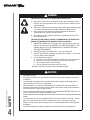 4
4
-
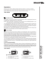 5
5
-
 6
6
-
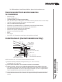 7
7
-
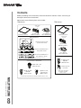 8
8
-
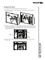 9
9
-
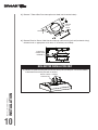 10
10
-
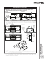 11
11
-
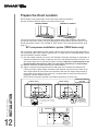 12
12
-
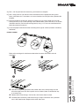 13
13
-
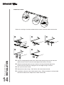 14
14
-
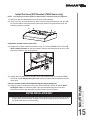 15
15
-
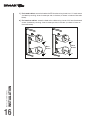 16
16
-
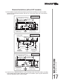 17
17
-
 18
18
-
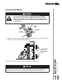 19
19
-
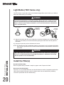 20
20
-
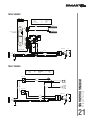 21
21
-
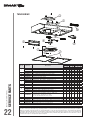 22
22
-
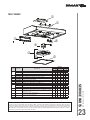 23
23
-
 24
24
-
 25
25
-
 26
26
-
 27
27
-
 28
28
-
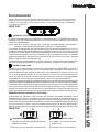 29
29
-
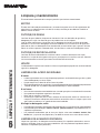 30
30
-
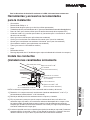 31
31
-
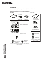 32
32
-
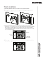 33
33
-
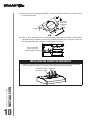 34
34
-
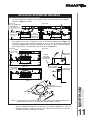 35
35
-
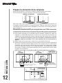 36
36
-
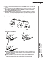 37
37
-
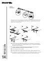 38
38
-
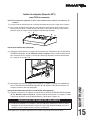 39
39
-
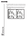 40
40
-
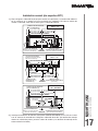 41
41
-
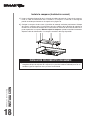 42
42
-
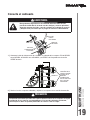 43
43
-
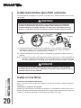 44
44
-
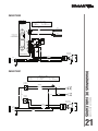 45
45
-
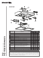 46
46
-
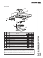 47
47
-
 48
48


Broan BNDF130BL Guía de instalación
- Categoría
- Campanas de cocina
- Tipo
- Guía de instalación
En otros idiomas
- English: Broan BNDF130BL Installation guide
Documentos relacionados
-
Broan QP130SS Instrucciones de operación
-
Broan BXT130BL Guía de instalación
-
Broan BXT130BL Manual de usuario
-
Broan SPE136SS Guía de instalación
-
Broan ALT330SS Guía de instalación
-
-
-
Broan VAUTOW Guía del usuario
-
Broan 90291-WI-01 Manual de usuario
Otros documentos
-
Kenmore 51282 El manual del propietario
-
 Kenmore Elite 233.51353 El manual del propietario
-
 Kenmore Elite 51413 El manual del propietario
-
Kenmore 51269 El manual del propietario
-
-
 Kenmore Elite 23351289710 El manual del propietario
-
 Kenmore Elite 23351353710 El manual del propietario
-
 Kenmore Elite 23351403710 El manual del propietario
-
 Kenmore Elite 51403 Guía de instalación
-
NuTone AR1 Series Guía de instalación


