Kenmore Elite 51403 Guía de instalación
- Categoría
- Campanas de cocina
- Tipo
- Guía de instalación

Use & Care / Installation Manual
Manual de Uso y Cuidado / Instalación
English / Español
Models/Modelos 51403*, 51413*
Kenmore Elite
®
Range Hood
Campana de cocina
* = width, anchura
P/N 99045662-002A
Sears Brands Management Corporation,
Hoff man Estates, IL 60179 USA
www.kenmore.com
www.sears.com
TM

2
READ AND SAVE THESE INSTRUCTIONS
TABLE OF CONTENTS KENMORE LIMITED WARRANTY
SECTION .............................................................PAGE
Warranty ................................................................................ 2
Safety Instructions ................................................................3
Operation ...............................................................................4
Cleaning .................................................................................5
Parts Included With Hood ..................................................6
Parts Not Included With Hood ..........................................6
Tools Needed ........................................................................6
Equivalent Duct Length Chart ............................................7
Install Ductwork ...................................................................8
Prepare The Hood ......................................................... 8-10
Prepare The Hood Location .........................................11-15
EZ1 One-Person Installation .................................11-12
Install The Hood (EZ1 Brackets) ................................13
Standard Installation (without EZ1 Brackets) ........ 14
Install The Hood (Standard Installation) ................ 15
Connect The Wiring ........................................................... 16
Install The Filters ................................................................ 16
Service Parts .......................................................................17
Master Protection Agreements ........................................ 18
When this appliance is installed, operated and maintained
according to all supplied instructions, the following warranty
coverage applies. To arrange for warranty service, call
1-800-4-MY-HOME® (1-800-469-4663).
• For one year from the date of purchase, any part of
this product that fails due to a defect in material or
workmanship will receive free repair or replacement if
repair proves impossible. The length of this coverage
does not apply to the fi nish of any painted or bright
metal part.
• For thirty days date of purchase, any painted or bright
metal part of this product will be replaced free of charge
if its fi nish is defective in material or workmanship.
All warranty coverage is void if this product is ever used for
other than private household purposes.
This warranty covers only defects in material and
workmanship, and will NOT pay for:
1. Consumable parts that can wear out from normal use,
including but not limited to fi lters, belts, light bulbs, and
bags.
2. A service technician to instruct the user in correct product
installation, operation or maintenance.
3. A service technician to clean or maintain this product.
4. Damage to or failure of this product if it is not installed,
operated or maintained according to the all instructions
supplied with the product.
5. Damage to or failure of this product resulting from
accident, abuse, misuse or use for other than its
intended purpose.
6. Damage to or failure of this product caused by the use
of detergents, cleaners, chemicals or utensils other than
those recommended in all instructions supplied with the
product.
7. Damage to or failure of parts or systems resulting from
unauthorized modifi cations made to this product.
Disclaimer of implied warranties; limitation of remedies
Customer’s sole and exclusive remedy under this limited
warranty shall be product repair as provided herein.
Implied warranties, including warranties of merchantability
or fi tness for a particular purpose, are limited to one
year or the shortest period allowed by law. Sears shall
not be liable for incidental or consequential damages.
Some states and provinces do not allow the exclusion
or limitation of incidental or consequential damages, or
limitation on the duration ofi mplied warranties of
merchantability or fi tness, so these exclusions or limitations
may not apply to you.
This warranty gives you specifi c legal rights, and you may
also have other rights which vary from state to state.
Sears Brands Management Corporation,
Hoff man Estates, IL 60179

3
Warranty Safety CleaningOperation Installation Service Parts
WARNING
TO REDUCE THE RISK OF FIRE, ELECTRIC SHOCK, OR
INJURY TO PERSONS, OBSERVE THE FOLLOWING:
1. Use this unit only in the manner intended by the
manufacturer. If you have questions, contact the
manufacturer at the address listed in the warranty.
2. Before servicing or cleaning unit, switch power off
at service panel and lock the service disconnecting
means to prevent power from being switched on
accidentally. When the service disconnecting means
cannot be locked, securely fasten a prominent warning
device, such as a tag, to the service panel.
3. Installation work and electrical wiring must be done by
a qualifi ed person(s) in accordance with all applicable
codes and standards, including fi re-rated codes and
standards.
4. Suffi cient air is needed for proper combustion and
exhausting of gases through the fl ue (chimney) of fuel
burning equipment to prevent backdrafting. Follow
the heating equipment manufacturer’s guideline and
safety standards such as those published by the
National Fire Protection Association (NFPA), and the
American Society for Heating, Refrigeration and Air
Conditioning Engineers (ASHRAE), and the local code
authorities.
5. When cutting or drilling into wall or ceiling, do not
damage electrical wiring and other hidden utilities.
6. To reduce the risk of fi re or electric shock, do not
use this range hood with an additional speed control
device.
7. Ducted fans must always be vented to the outdoors.
8. To reduce the risk of fi re, use only metal ductwork.
9. This unit must be grounded.
TO REDUCE THE RISK OF A RANGE TOP GREASE FIRE:
1. Never leave surface units unattended at high settings.
Boilovers cause smoking and greasy spillovers that
may ignite. Heat oils slowly on low or medium settings.
2. Always turn hood ON when cooking at high heat or
when cooking fl aming foods.
3. Clean ventilating fans frequently. Grease should not
be allowed to accumulate on fan or fi lter.
4. Use proper pan size. Always use cookware appropriate
for the size of the surface element.
WARNING
TO REDUCE THE RISK OF INJURY TO PERSONS IN THE
EVENT OF A RANGE TOP GREASE FIRE, OBSERVE THE
FOLLOWING:*
1. SMOTHER FLAMES with a close-fi tting lid, cookie
sheet, or metal tray, then turn off the burner. BE
CAREFUL TO PREVENT BURNS. If the fl ames do not
go out immediately, EVACUATE AND CALL THE FIRE
DEPARTMENT.
2. NEVER PICK UP A FLAMING PAN - You may be
burned.
3. DO NOT USE WATER, including wet dishcloths or
towels - a violent steam explosion will result.
4. Use an extinguisher ONLY if:
A. You know you have a Class ABC extinguisher and
you already know how to operate it.
B. The fi re is small and contained in the area where
it started.
C. The fi re department is being called.
D. You can fi ght the fi re with your back to an exit.
* Based on “Kitchen Fire safety Tips” published by NFPA.
CAUTION
1. For general ventilating use only. Do not use to exhaust
hazardous or explosive materials and vapors.
2. To avoid motor bearing damage and noisy and/
or unbalanced impellers, keep drywall spray,
construction dust, etc. off power unit.
3. For best capture of cooking impurities, your range
hood should be mounted so that the top of the hood
is 18-30” above the cooking surface.
4. Use only with range hood cord-connection kits that
have been investigated and found acceptable for use
with this model range hood.
5. Please read specifi cation label on product for further
information and requirements.
SAFETY INSTRUCTIONS
!
NOTE
If hood is to be installed Non-Ducted:
Purchase non-ducted fi lters and attach them to the
aluminum mesh fi lters.
!
INTENDED FOR DOMESTIC COOKING ONLY.
!
“Non-ducted Filters” available by calling Sears at
1-800-4-MY-HOME
®

4
OPERATION
BLOWER ACTIVATION/SPEED LEVEL CHANGE/
FILTER INDICATOR RESET
When blowers are OFF, press on this push button to turn
ON the blowers at the last saved speed. If there was
no speed saved, the blowers will be set on LOW speed.
NOTE: When LOW speed is activated from OFF,
the blowers start on MEDIUM speed for a very
short lapse of time, and then resume to LOW
speed.
To change the blower speed, press on this push button
again until the desired speed is reached (from LOW to
MEDIUM to HIGH speed to OFF). Each time a blower
speed is activated, a rotating blower icon appears on
left side of LCD screen, with dot(s) under it (the rotation
speed shows the chosen speed: slow for LOW with
one dot, faster for MEDIUM with 2 dots and fastest for
HIGH with 3 dots).
When blowers are on (no matter the speed level),
press and hold this push button until the blower icon
disappears from the LCD screen; this will turn off the
blowers and save the blower speed chosen.
Heat Sentry™
This hood is equipped with a protective device that
activates the blowers when an abnormally high heat
level is detected while the blowers are activated. During
the Heat Sentry activation, this device takes control of
the blowers and set them on MEDIUM speed while all
dots under the blower icon blink. However, the lights can
be still controlled. The blowers will remain on MEDIUM
speed until the heat is back to normal, they then return
to the speed previously selected.
NOTE: When excessive heat is detected, Heat Sentry
will shut off both blowers and lights while all
dots under the blower icon will blink faster.
Both blowers and lights will remain off until the
ambient temperature cools down; the blowers
will then start on MEDIUM speed (the lights
can be controlled again). The blowers will remain
on MEDIUM speed until the heat is back
to normal, they then return to the speed
previously selected.
1
NOTE: At range hood start-up or after a power failure,
a small icon (1) appears shortly (for ± 2 seconds)
on LCD screen; this is normal.
DELAY OFF
When the blowers are on, press this button to activate
the delay function. This icon appears on LCD screen
beside the blower icon to indicate the function is on.
The blowers will continue to operate for 10 minutes and
then, will shut off automatically (both blower and delay
icons will disappear from LCD screen). When Delay off
is activated, it is possible to change the blower speed
by pressing on blower push button without aff ecting the
remaining time of the delay.
To cancel the delay off function before the end of the
10-minute cycle, press again on delay off push button.
OPERATION
ON LIGHTING/LIGHT INTENSITY CHANGE
Press this push button to turn on the lights at the last
saved intensity; the light icon appears on right side
of LCD screen and the number of dots below it shows
which light intensity is on (one dot for LOW, two dots
for MEDIUM and three dots for HIGH).
To change the light intensity, press the push button
until the desired level is reached (from HIGH intensity,
pressing again will shut off the lights).
When lights are on (no matter the light intensity), press
and hold this push button until the light icon disappears
from the LCD screen; this will shut off the lights and
save the chosen light intensity.
The LED modules included with this hood are the
latest in LED cooktop illumination technology specially
designed to operate in the elevated temperatures of
cooking - off ering bright lighting and lasting up to 25
times as long as a standard bulb and greater reliability
than typical replacement LED bulbs.
MASTER ON/OFF
Press this push button to turn on the ligths and the
blowers at the last saved intensity. When either lights
or blowers are ON, pressing on this push button will
memorize the current blower speed and lighting level
prior to shut them OFF.
FILTER CLEANING REMINDER
This icon appears on LCD screen 30 seconds after
turning OFF the blowers when it is time to clean hood
and fi lters (refer to Cleaning and Maintenance on page
5). This happens every time the blowers are turned OFF
until the fi lter cleaning reminder has been reset. Once
the cleaning is done, reset the fi lter cleaning reminder by
pressing on blower activation push button for 3 seconds
while the icon appears on LCD screen for 30 seconds.

5
Warranty Safety CleaningOperation Installation Service Parts
WARNING: To reduce the risk of electric shock,
disconnect from power supply before cleaning.
Hybrid fi lters
Clean frequently using hot water and a mild
detergent or in your dishwasher. The hybrid fi lters
should be washed approximately every month
depending on the amount of usage. Wash more often
if your cooking style generates greater grease - like
frying foods or wok cooking.
Non-ducted recirculation fi lters
(available separately - see page 6)
The non-ducted recirculation fi lters should be changed
every 3 to 6 months. Replace more often if your
cooking style generates extra grease, such as
frying and wok cooking. Refer to installation
instructions included with non-ducted recirculation
fi lters.
Stainless steel hood surfaces
Do:
• Regularly wash with clean cloth or rag soaked
with warm water and mild soap or liquid dish
detergent.
• Always clean in the direction of original polish
lines.
• Always rinse well with clear water (2 or 3 times)
after cleaning. Wipe dry completely.
• You may also use a specialized household stainless
steel cleaner.
Don’t:
• Use any steel or stainless steel wool or any other
scrapers to remove stubborn dirt.
• Use any harsh or abrasive cleansers.
• Allow dirt to accumulate.
• Let plaster dust or any other construction residues
reach the hood. During construction/renovation,
cover the range hood to make sure no dust sticks
to the stainless steel surface.
Avoid when choosing a detergent:
• Any cleaners that contain bleach will attack
stainless steel.
• Any products containing: chloride, fl uoride, iodide,
bromide will deteriorate surfaces rapidly.
• Any combustible products used for cleaning such
as acetone, alcohol, ether, benzol, etc., are highly
explosive and should never be used close to a
range.
Blower assembly
The center of the fan wheels should be cleaned
frequently. Use a clean cloth soaked with warm
detergent solution.
The motors are permanently lubricated and never
need oiling. If the motor bearings make excessive or
unusual noise, replace the motor with the exact service
motor. The fan wheel should also be replaced.
CLEANING

6
PARTS INCLUDED WITH HOOD
TOOLS NEEDED FOR HOOD INSTALLATION
Hybrid Grease Filters
(2 per hood)
Parts Bag
(4 no. 8-18 x 1/2" metal screws,
4 washers, 6 no. 8 x 5/8" round head
wood screws, 6 no. 8 x 1/2" countersunk
wood screws)
Screwdriver
(Flat & Phillips no. 2)
Nutdriver
11/32"
Tape
Measure
Drill
(with 1/8" and
7/64" drill bits,
and 1½" hole saw)
Sabre Saw
Keyhole
Saw
-or-
Metal Foil
Duct Tape
Wire
Stripper
PARTS NOT INCLUDED WITH HOOD
OPTIONAL PARTS (purchase separately)
7-inch Round Damper
(For use with 7-inch Round Duct)
Sears Part No. 59183
Ducting Accessories
(See “Equivalent Duct Length Chart” on page 6 for
Ducting Accessory Model Nos.)
“Parts Not Included With Hood” available by calling
Sears at 1-800-4-MY-HOME
®
3¼” x 10”
Damper / Duct Connector
C
L
AB
Apoyar este borde contra la pared de atrásPlace this edge against back wall
VERTICAL EXHAUST
S
A
A
V
RTICAL EX
= 3¼” x 10”
= 3¼” x 14”
RECTANGULAR DUCTING7” ROUND DUCTING
OR
Use this template for marking; do not attempt to cut out the ducting hole through it.
NOTE: These cutouts are clearance holes; they do not need to be the exact size of ducting.
= 3¼ po x 10 po
= 3¼ po x 14 po
CONDUIT RECTANGULAIRECONDUIT ROND DE 7 PO
OU
= 3¼ pulg. x 10 pulg.
= 3¼ pulg. x 14 pulg.
CONDUCTO RECTANGULARCONDUCTO REDONDO
DE
7 PULG.
O
Appuyer ce bord au mur arrière
Utiliser ce gabarit pour marquer vos repères; ne pas tenter de découper
le trou pour le conduit à travers le gabarit.
NOTE : Les découpes incluent le jeu nécessaire à l’installation; elles ne doivent pas
être du format exact des conduits.
Use esta plantilla para crear marcados; no trate de cortar el
agujero del conducto a través de la plantilla.
NOTA: To be translated in Spanish.
MARK WHERE INDICATED
FOR THE APPROPRIATE SIZE DUCT OPENING
MARQUER LES REPÈRES AUX ENDROITS INDIQUÉS SELON
LE FORMAT DE CONDUIT UTILISÉ
TITLE TO BE TRANSLATED IN SPANIS H
Electrical access hole center
A = single blower hood
B = double blower hood
Centre du trou pour fil
d’alimentation électrique
A = hotte ventilateur simple
B = hotte ventilateur double
To be translated in Spanish
Electrical access hole center
A = single blower hood
B = double blower hood
4¼”
10½”
14½”
8”
7½”
C
C
C
Bend template along graduated
scale when installing to framed
cabinet.
Pour une installation sous une
armoire à fond en retrait, utiliser les
lignes pour mesurer l’épaisseur du
décalage causé par le mur de
l’armoire et plier le gabarit en
conséquence.
To be translated in Spanish.
EZ-1 One person Installation Kit
(including template for
ducting, printed both sides,
and installation brackets)
7” Round Duct Connector
Long Nose
Pliers
HR0064
Sheet Metal
Shears
Pencil
Non-Ducted Recirculation Filters
(Non-ducted hoods only)
(2 per hood)
Part Nos.:
S97020466 (30-in. width hoods)
S97020467 (36-in. width hoods)

7
Warranty Safety CleaningOperation Installation Service Parts
EQUIVALENT DUCT LENGTH CHART
Broan Model 401
Straight Duct
3¼-in. x 10-in. x 2-ft. long
Equivalent length
2 ft.
Broan Model 415
7-in. Round Elbow
Equivalent length
8 ft.
Broan Model 428
3¼-in. x 10-in.
Right-angle Elbow
Equivalent length
8.5 ft.
Broan Model 429
3¼-in. x 10-in.
Right-angle Flat Elbow
Equivalent length
24 ft.
Broan Model 430
3¼-in. x 10-in.
Right-angle
Short
Eave Elbow
Equivalent length
15 ft.
Broan Model 431
3¼-in. x 10-in.
Right-angle
Long
Eave Elbow
Equivalent length
15 ft.
Sears Model
59391
3¼-in. x
10-in.
Wall Cap
Equivalent
length
45 ft.
(7-ft. w/o
damper)
Sears
Model 59091
Roof Cap
(accepts 7-in. round
or 3¼-in. x 10-in. duct)
Equivalent length
30 ft. (7-ft. w/o damper)
Kenmore range hoods are designed to perform effi ciently when attached to long runs of duct. As a point of reference,
this hood will function at approximately 80% of its rated air fl ow when 30 equivalent feet of 7" round ductwork is
attached. Use this chart to calculate the equivalent duct length of your system.
Broan Model 407
Straight Duct
7-in. round x 2-ft. long
Equivalent length
2 ft.
Broan Model 412H
3¼-in. x 10-in. to
7-in. Round
Transition
Equivalent length
5.5 ft.
Broan Model 647
7-in. Round
Wall Cap
Equivalent length
34 ft.
(6-ft. w/o damper)
Sears Model “Ducting Accessories” available by calling:
Sears at 1-800-4-MY-HOME
®
Broan Model “Ducting Accessories” available by calling:
1-800-558-1711.

8
SOFFIT
18" MIN - 30" MAX
ABOVE
COOKING SURFACE
CABINET
3¼" X 10" DUCT
(FOR HORIZONTAL DISCHARGE)
WALL CAP
ROOF CAP
3¼" X 10" OR
7" ROUND DUCT
(FOR VERTICAL
DISCHARGE
)
HOUSE WIRING
(TOP OR BACK OF HOOD)
HOOD
1. Determine whether hood will discharge vertically
(3¼” x 10” or 7” Round) or horizontally (3¼” x 10”
only).
2. Run ductwork between the hood location and a roof
cap or wall cap.
3. Choose a straight, short duct run to allow the hood to
perform most effi ciently. Long duct runs, elbows and
transitions will reduce the performance of the hood.
Use as few of them as possible. When possible, use
at least 2 foot straight runs before any turns. Larger
ductwork may be required for best performance with
longer duct runs.
4. Install wall cap or roof cap (sold separately). Connect
metal ductwork to cap and work back towards the
hood location. Use 2” metal foil duct tape to seal the
joints between ductwork sections.
INSTALL DUCTWORK (DUCTED INSTALLATION ONLY)
NOTE: Distances over 30” are at the installer and user
discretion.
1. If present, remove all protective polyfi lm from the
hood and/or parts. Remove 7” Round Duct Plate
from top/back of hood (see illustration at right).
Keep the screws for further use.
PREPARE THE HOOD
2. Using the fi nger cup, remove the Hybrid Filters from
the hood by pushing down and tilting fi lters out.
7” ROUND
DUCT PLATE
SCREWS
B
C

9
Warranty Safety CleaningOperation Installation Service Parts
3. Using a 11/32” nut driver, remove the lock nut retaining
the fl ange of the right blower cover plate (shaded part
on illustration beside) to the inner back of hood (see
inset). Remove the right cover plate retaining screws
(7 screws), then set the blower cover along with its
screws and nut aside.
NOTE: Sightly lift up the cover plate before sliding it
towards the left to remove it.
1
2
3
45
6
7
BACK OF HOOD
LOCK NUT
ELECTRICAL
POWER
CABLE
KNOCKOUT
5. Remove Electrical Power Cable Knockout from top
(vertical exhaust) or back (horizontal exhaust) of
hood. For knockout removed from back of hood,
install an appropriate strain relief, 1/2” diameter
(not included). For knockout removed from top of
hood, the strain relief will be installed later.
EZ1
BRACKETS
4. Remove the parts bag, taped on the inner back of
hood, near the left corner. Remove the EZ1 brackets
from inside the hood by cutting off the tie wrap.
Discard the tie wrap.
PARTS BAG LOCATION
RECIRCULATION
COVER PLATE
SCREWS
NON-DUCTED INSTALLATIONS ONLY
6. Remove 3 screws retaining the recirculation cover plate to the hood. Discard this plate with its screws. Peel
off and discard the membrane (shaded part in illustration below) covering the recirculation grille, ensuring the
openings are totally cleared.

10
DUCTED INSTALLATIONS ONLY
7. Remove 3¼” x 10” vertical, 3¼” x 10” horizontal (both are the rectangular central knockout plates, see
hatched areas), or 7-inch round knockout plate as appropriate for your ducting method (see FIGURES 1 A and
1 B).
3¼” X 10”
DAMPER
ASSEMBLY
SCREWS
3¼” X 10”
DAMPER
ASSEMBLY
SCREWS
7” ROUND
KNOCKOUT PLATE
(ALSO REMOVE VERTICAL
KNOCKOUT PLATE)
3¼” X 10”
VERTICAL
KNOCKOUT
PLATE
3¼” X 10”
HORIZONTAL
KNOCKOUT
PLATE
FIGURE 1 A FIGURE 1 B
NOTE: To accommodate off -center ductwork, the 7” round duct plate can be installed up to 1/2” on either
side of the hood center.
7” ROUND
DUCT
PLATE
SCREWS
FIGURE 3
FIGURE 2 A
TOP/BACK
EDGE OF
HOOD
DAMPER
FLAP
PIVOT
FIGURE 2 B
BACK OF
HOOD
DAMPER
FLAP
PIVOT
8. Attach 3¼” x 10” Damper Assembly on top OR back of hood (if using 3¼” x 10” duct; shaded part in FIGURE 2 A)
or 7” Round Duct Plate (if using 7-inch round duct, FIGURE 3) over the knockout opening. When installed, the
3¼” x 10” damper assembly must open as shown in FIGURE 2 B.
TIP: Insert a small length of duct over the 3¼” x 10” damper assembly (for rectangular ducting) or 7” round (for
round ducting) and seal the joint using aluminum foil duct tape to ease connection with the house ductwork.

11
Warranty Safety CleaningOperation Installation Service Parts
PREPARE THE HOOD LOCATION
NOTE: Before starting installation, read all the steps
of these instructions.
Use the illustration beside to identify your kitchen
cabinet type.
EZ1 One-person installation system
This manual covers 2 kinds of installation: the standard
(without EZ1 brackets) and the EZ1 one-person
installation system (using included template and
brackets). For the standard installation, go to page 14.
FRAMED CABINET FRAMELESS CABINET
CABINET FRONT
C
L
AB
Apoyar este borde contra la pared de atrásPlace this edge against back wall
VERTICAL EXHAUST
A
S
A
A
V
RTICAL EX
= 3¼” x 10”
= 3¼” x 14”
RECTANGULAR DUCTING7” ROUND DUCTING
OR
Use this template for marking; do not attempt to cut out the ducting hole through it.
NOTE: These cutouts are clearance holes; they do not need to be the exact size of ducting.
= 3¼ po x 10 po
= 3¼ po x 14 po
CONDUIT RECTANGULAIRECONDUIT ROND DE 7 PO
OU
= 3¼ pulg. x 10 pulg.
= 3¼ pulg. x 14 pulg.
CONDUCTO RECTANGULARCONDUCTO REDONDO
DE
7 PULG.
O
Appuyer ce bord au mur arrière
Utiliser ce gabarit pour marquer vos repères; ne pas tenter de découper
le trou pour le conduit à travers le gabarit.
NOTE : Les découpes incluent le jeu nécessaire à l’installation; elles ne doivent pas
être du format exact des conduits.
Use esta plantilla para crear marcados; no trate de cortar el
agujero del conducto a través de la plantilla.
NOTA: To be translated in Spanish.
MARK WHERE INDICATED
FOR THE APPROPRIATE SIZE DUCT OPENING
MARQUER LES REPÈRES AUX ENDROITS INDIQUÉS SELON
LE FORMAT DE CONDUIT UTILISÉ
TITLE TO BE TRANSLATED IN SPANISH
Electrical access hole center
A = single blower hood
B = double blower hood
Centre du trou pour fil
d’alimentation électrique
A = hotte ventilateur simple
B = hotte ventilateur double
To be translated in Spanish
Electrical access hole center
A = single blower hood
B = double blower hood
4¼”
10½”
14½”
8”
7½”
C
C
C
Bend template along graduated
scale when installing to framed
cabinet.
Pour une installation sous une
armoire à fond en retrait, utiliser les
lignes pour mesurer l’épaisseur du
décalage causé par le mur de
l’armoire et plier le gabarit en
conséquence.
To be translated in Spanish.
P
C
CABINET FRONT
C
L
AB
VERTICAL EXHAUST
A
S
A
A
V
RTICAL EX
= 3¼” x 10”
= 3¼” x 14”
RECTANGULAR DUCTING7” ROUND DUCTING
OR
Use this template for marking; do not attempt to cut out the ducting hole through it.
NOTE: These cutouts are clearance holes; they do not need to be the exact size of ducting.
= 3¼ po x 10 po
= 3¼ po x 14 po
CONDUIT RECTANGULAIRECONDUIT ROND DE 7 PO
OU
= 3¼ pulg. x 10 pulg.
= 3¼ pulg. x 14 pulg.
CONDUCTO RECTANGULARCONDUCTO REDONDO
DE
7 PULG.
O
Utiliser ce gabarit pour marquer vos repères; ne pas tenter de découper
le trou pour le conduit à travers le gabarit.
NOTE : Les découpes incluent le jeu nécessaire à l’installation; elles ne doivent pas
être du format exact des conduits.
Use esta plantilla para crear marcados; no trate de cortar el
agujero del conducto a través de la plantilla.
NOTA: To be translated in Spanish.
MARK WHERE INDICATED
FOR THE APPROPRIATE SIZE DUCT OPENING
MARQUER LES REPÈRES AUX ENDROITS INDIQUÉS SELON
LE FORMAT DE CONDUIT UTILISÉ
TITLE TO BE TRANSLATED IN SPANISH
Electrical access hole center
A = single blower hood
B = double blower hood
Centre du trou pour fil
d’alimentation électrique
A = hotte ventilateur simple
B = hotte ventilateur double
To be translated in Spanish
Electrical access hole center
A = single blower hood
B = double blower hood
4¼”
10½”
14½”
8”
7½”
C
C
C
Bend template along graduated
scale when installing to framed
cabinet.
Pour une installation sous une
armoire à fond en retrait, utiliser les
lignes pour mesurer l’épaisseur du
décalage causé par le mur de
l’armoire et plier le gabarit en
conséquence.
To be translated in Spanish.
ELECTRICAL
ACCESS HOLE
LOCATION (B)
(
IN CABINET BOTTOM)
CENTER LINE
FOLD TEMPLATE ALONG GRADUATED
SCALE
WHEN INSTALLING TO FRAMED
CABINET
.
B
VERTICAL
EXHAUST DUCTING
EZ1 installation is designed for use with kitchen cabinets that have the same width designation as the range
hood width. If the cabinet is greater than 1/2” wider than the range hood width, please use the standard
installation method.
1. Use the proper template for vertical OR horizontal
disharge (included) for placement of ductwork and
electrical cutout in cabinet or wall. For a non-ducted
installation, DO NOT cut a duct access hole, only cut
the hole for electrical wiring. If replacing a hood and
plan to use the existing duct and electrical, steps 2 to
5 may not be necessary. If so, skip to step 6.
2. Measure and mark the hood center line on cabinet
bottom.
3. Align the center line on template with the hood
center line marked on the bottom of the cabinet,
placing the edge (where indicated) of the template
against back wall. When using with framed cabinet
for vertical exhaust installation, fold over rear edge
of template equal to the depth of the cabinet frame
at the wall (use graduations on template, C locations
on template). Tape the template in place.
NOTE: When facing the installation, A and B (on
template) must be at right.
ELECTRICAL
ACCESS HOLE
LOCATION (B)
(
IN WALL)
CENTER LINE
C
L
AB
Place this edge against
cabinet bottom.
Appuyer ce bord contre le bas
de l’armoire.
Apoyar este borde contra
la base del armario.
T
T
= 3¼ pulg. x 10 pulg.
= 3¼ pulg. x 14 pulg.
CONDUCTO RECTANGULAR
= 3¼” x 10”
= 3¼” x 14”
RECTANGULAR DUCTING
= 3¼ po x 10 po
= 3¼ po x 14 po
CONDUIT RECTANGULAIRE
MARK WHERE INDICATED
FOR THE APPROPRIATE SIZE DUCT OPENING
MARQUER LES REPÈRES AUX ENDROITS INDIQUÉS SELON
LE FORMAT DE CONDUIT UTILISÉ
TITLE TO BE TRANSLATED IN SPANISH
Use this template for marking; do not attempt to cut out the ducting hole through it.
NOTE: These cutouts are clearance holes; they do not need to be the exact size of ducting.
Utiliser ce gabarit pour marquer vos repères; ne pas tenter de découper
le trou pour le conduit à travers le gabarit.
NOTE : Les découpes incluent le jeu nécessaire à l’installation; elles ne doivent pas
être du format exact des conduits.
Use esta plantilla para crear marcados; no trate de cortar el
agujero del conducto a través de la plantilla.
NOTA: To be translated in Spanish.
Electrical access hole center
A = single blower hood
B = double blower hood
Centre du trou pour fil
d’alimentation électrique
A = hotte ventilateur simple
B = hotte ventilateur double
To be translated in Spanish
Electrical access hole center
A = single blower hood
B = double blower hood
B
ess hole center
wer hood
wer hood
HORIZONTAL
EXHAUST DUCTING
4. Drill a 1/8” dia. pilot hole for house wiring,
at B location on template.
5. Use a sharp pencil or 1/8” drill bit to mark the
locations for the appropriate duct access holes
(16 locations for 7” round duct, or 4 corner locations
for rectangular duct). Remove the template.
6. Draw the border for the exhaust ducting by linking its
marks (16 for round duct and 4 for rectangular duct),
then cut the opening in the cabinet bottom (vertical
exhaust) or in the wall (horizontal exhaust). Drill the
house wiring hole by using a 1½” hole saw centered
with the pilot hole previously made in 4.

12
FRAMED CABINET
7/64”
XY
Z
Refer to the marking on the brackets to determine
the correct installation side and orientation.
Mate the corresponding bracket to the cabinet
side frame, while placing rear end of bracket
against the wall. Use a pencil to mark 3 holes
(there are 6 holes but only 3 are necessary).
Remove the bracket. Using a 7/64” drill bit,
drill 3 holes where marked.
Assemble the bracket to the side frame using a
Phillips screwdriver and 3 provided no. 8 x 5/8”
wood screws. Repeat for the other side frame.
7. Install the proper installation brackets according to
the type of cabinet (framed or frameless). See below.
[ \
7/64”
X
3 X
Y
Z
Align the corresponding bracket to the cabinet
side, while placing rear end of bracket against
the wall. Draw a line on the outer edge of the
bracket (as shown).
Slide the bracket towards the center of cabinet
and align the outside edge of the bracket with the
marked line, keeping the rear end edge leaning
on the wall.
Use a pencil to mark 3 holes.
Remove the bracket. Using a 7/64” drill bit,
drill 3 holes where marked.
Assemble the bracket to the cabinet bottom using
a Phillips screwdriver and 3 provided countersunk
wood screws. Repeat for the other cabinet side
.
FRAMELESS CABINET
Refer to the marking on the brackets to determine
the correct installation side and orientation.

13
Warranty Safety CleaningOperation Installation Service Parts
A
B
D
C
HORIZONTAL EXHAUST INSTALLATION ONLY
A
B
Install the hood (EZ1 brackets)
NOTE: The following procedure applies to both
framed or frameless cabinet installations.
1. Run house power cable between service panel and
hood location.
2. There are 2 pairs of recessed holes on each side
of the top of the hood (on rear: A and B, on front
C and D on illustration beside); these holes allow
the range hood to hang on the brackets (previously
installed).
3. Temporarily hang the hood on the brackets using its
2 recessed REAR HOLES (A and B). While holding
the hood, run the house power cable into the hood
through the strain relief previously installed i
n step
5 on page 9.
4. Unhook the rear holes from the brackets and hang
the hood using its 2 recessed FRONT HOLES (C and
D). While holding the hood, go to step 6.
VERTICAL EXHAUST INSTALLATION ONLY
5. Hang the hood on the brackets using the 2 recessed
FRONT HOLES (C and D). While holding the hood,
tighten an appropriate strain relief, 1/2” diameter
(not included) to the power cable, then insert the
strain relief in the knockout hole.
DUCTED INSTALLATIONS ONLY
6. Connect the ductwork to the hood and use metal foil duct tape to make joints secure and air-tight. Make sure
the damper assembly (or round duct plate) enters the ductwork and that the damper opens and closes freely.
FRAMED CABINET FRAMELESS CABINET
WOOD
SCREWS
METAL
SCREWS
7. For framed cabinet, secure the hood to the EZ1
brackets using 4 no. 8-18 x 1/2” metal screws with
washers (screws and washers included in parts
bag). Insert 2 screws and washers per side, in the
slots (as shown in inset on illustration beside).
8. For frameless cabinet, secure the hood to the
cabinet using 4 no. 8 x 5/8” round head wood
screws (screws and washers included in parts bag).
Insert 2 screws and washers per side, in the slots (as
shown in inset on illustration beside).
9. Attach power cable to the hood using the strain
relief.

14
3¼” x 10”
VERTICAL DUCTING
3¼” x 10”
HORIZONTAL DUCTING
7” ROUND
VERTICAL DUCTING
1. Use these diagrams for proper placement of ductwork
and electrical cutout in cabinet or wall.
For a non-ducted installation, DO NOT cut a duct
access hole, only cut the hole for electrical wiring
Standard Installation (without EZ1 brackets)
VERTICAL DUCT
ACCESS HOLE
5¼"
5¼"
CENTER LINE
ELECTRICAL ACCESS
HOLE (
IN CABINET BOTTOM)
WOOD SHIMS
(
RECESSED-BOTTOM
CABINETS
ONLY)
CABINET FRONT
3/4"
1⅜"
1½"
9¾"
4
7
/16"
CABINET
BOTTOM
REAR HOOD MOUNTING SCREWS (2)
12⅞" (30" HOOD)
15⅞" (36"
HOOD)
12⅞" (30"
HOOD)
15⅞" (36"
HOOD)
CABINET
BOTTOM
CABINET FRONT
HORIZONTAL DUCT
ACCESS HOLE
REAR HOOD
MOUNTING
SCREWS (2)
ELECTRICAL
ACCESS HOLE
(
IN WALL)
3⅞"
CENTER
LINE
WOOD SHIMS
(
RECESSED-BOTTOM
CABINETS
ONLY)
13/16"
3/16"
5¼"
5¼"
9¾"
12⅞" (30"
HOOD)
15⅞" (36"
HOOD)
12⅞" (30"
HOOD)
15⅞" (36"
HOOD)
4¹¹/16"
8" DIA.
HOLE
7-IN. ROUND
7-IN. ROUND
DUCT
DUCT
ACCESS
ACCESS
HOLE
HOLE
7-IN. ROUND
DUCT
ACCESS
HOLE
1½"
1⅜"
9¾"
CENTER LINE
ELECTRICAL ACCESS
HOLE (
IN CABINET BOTTOM)
REAR HOOD MOUNTING SCREWS (2)
WOOD SHIMS
(
RECESSED-BOTTOM
CABINETS
ONLY)
12⅞" (30" HOOD)
15⅞" (36"
HOOD)
12⅞" (30"
HOOD)
15⅞" (36"
HOOD)
2. Install part-way two (2) ROUND HEAD no. 8 x 5/8”
mounting screws into shims/cabinet, according to the
proper diagram above, the other 2 ROUND HEAD
no. 8 x 5/8” mounting screws will be used later.
(Mounting screws are included in parts bag, but wood
shims and shim mounting screws are not included).

15
Install the Hood (Standard Installation)
1. Run house power cable between service panel and
hood location. For hood with power cable access
located on back of hood, run the house power cable
into the hood through the strain relief previously
installed in step 8 on page 8. For hood with power
cable access located on top, tighten the strain relief
to the power cable before inserting the strain relief
in the knockout hole.
2. Hang hood from (2) mounting screws previously installed.
Slide hood back towards wall until mounting screw
heads are engaged in narrow end of keyhole slots in
top of hood. Tighten screws securely and maintain a
hold on the hood until completing step 3.
DUCTED INSTALLATIONS ONLY
4. Connect the ductwork to the hood and use metal foil duct tape to make joints secure and air-tight. Make sure
the damper assembly (or round duct plate) enters the ductwork and that the damper opens and closes freely.
NOTE: Two installers are recommended because of the weight of this hood.
Warranty Safety CleaningOperation Installation Service Parts
BACK OF HOOD
S
CREW PREVIOUSLY
TIGHTENED IN STEP 2
3. Secure the hood to the cabinet using 2 no. 8 x 5/8”
round head wood screws and 2 washers (screws and
washers included in parts bag). Insert 1 screw and
washer per side, in the slots (as shown beside. Attach
power cable to the hood using the strain relief.

16
WARNING: Risk of electric shock. Electrical
wiring must be done by qualifi ed personnel
in accordance with all applicable codes and
standards. Before connecting wires, switch
power off at service panel and lock service
disconnecting means to prevent power from
being switched on accidentally.
1. Connect House Power Cable to range hood wiring:
BLACK to BLACK, WHITE to WHITE and GREEN or
bare wire under GREEN ground screw.
2. Reinstall the blower cover plate (shaded part on
illustration beside) using the lock nut and7screws
previously removed in step 3 on page 9. Pay attention
to screw 1 location; from back of hood point of view, it
must be located on left side of the lock nut (see inset).
CONNECT THE WIRING
MOTORS
GROUND
WIRE
HOUSE
POWER
CABLE
GROUND
SCREW
Ducted Installation Only:
Re-install grease fi lters removed in step 2 on page 8,
under “Prepare the Hood”.
INSTALL THE FILTERS
“Non-ducted Filters” available by calling Sears at
1-800-4-MY-HOME
®
Non-ducted Installation Only:
Purchase two non-ducted fi lters (see part number in
Service parts list). Attach the non-ducted fi lters following
instructions packed with the non-ducted fi lters.
1
2
3
45
6
7
BACK OF HOOD
LOCK NUT
1

17
Warranty Safety CleaningOperation Service PartsInstallation
SERVICE PARTS
1
2
3
4
7
5
6
9
KEY NO. PART NO. DESCRIPTION
QUANTITY
51403 51413
1 S97020031 R
ECIRCULATION COVER PLATE, STAINLESS STEEL (INCLUDING SCREWS)11
2 SR680508 7'' R
OUND DUCT PLATE (INCLUDING SCREWS)11
3 S97020534 3¼”
X 10” DAMPER ASSEMBLY (INCLUDING SCREWS)11
4 S97020412 C
APACITOR 22
5 S97020842 B
LOWER ASS'Y CW (INCLUDING ITEMS 4 AND 6 AND HARDWARE)11
6 SR99420635 C
LIP FOR FANPELLER 11
7
S97020204-002 G
REASE FILTER - HYBRID - TYPE C1 (SET OF 2) 1
S97020204-003 G
REASE FILTER - HYBRID - TYPE D1 (SET OF 2) 1
8 S97020843 B
LOWER ASS'Y CCW (INCLUDING ITEMS 4 AND 6 AND HARDWARE)11
9 S97020797 A
UTOTRANSFORMER (WITH SCREWS)11
10 S97020444 LED
MODULE (PAIR)11
11 S97020438 LCD C
ONTROL (WITH SCREWS)11
12 S97020445 T
RANSFORMER 24 V 18 VA (WITH SCREWS)11
* S97020796 W
IRE HARNESS WITH AUTOTRANSFORMER AND FUSE 11
* S97020360
P
ARTS BAG INCLUDING: 4 METAL SCREWS NO. 8-18 X 1/2”,
4 WASHERS, 6 ROUND HEAD NO. 8 X 5/8” WOOD SCREWS,
6 NO. 8 X 1/2” COUNTERSUNK SCREWS
11
* S97020466 N
ON-DUCTED FILTER - TYPE XC (SET OF 2) (NON-DUCTED INSTALLATION ONLY)1
* S97020467 N
ON-DUCTED FILTER - TYPE XD (SET OF 2) (NON-DUCTED INSTALLATION ONLY)1
* S99527587 N
ON-DUCTED FILTER CLIP KIT (INCLUDES 4 CLIPS)11
* S97020470 E
ASY INSTALL KIT (INCLUDING HARDWARE)11
Order replacement parts by PART NO. - not by KEY NO.
* Not illustrated
R
EPLACEMENT PARTS AND REPAIRS
In order to ensure your unit remains in good working condition, you must use the manufacturer genuine replacement parts only.
The manufacturer genuine replacement parts are specially designed for each unit and are manufactured to comply with all
the applicable certifi cation standards and maintain a high standard of safety. Any third party replacement part used may
cause serious damage and drastically reduce the performance level of your unit, which will result in premature failing. The
manufacturer recommends to contact a certifi ed service depot for all replacement parts and repairs.
8
6
10
11
12

18
MASTER PROTECTION AGREEMENTS
Congratulations on making a smart purchase. Your new
Kenmore
®
product is designed and manufactured for
years of dependable operation. But like all products, it
may require preventive maintenance or repair from time
to time. That’s when having a Master Protection
Agreement can save you money and aggravation.
The Master Protection Agreement also helps extend the
life of your new product. Here’s what the Agreement*
includes:
Parts and labor needed to help keep products
operating properly under normal use, not just de-
fects. Our coverage goes well beyond the
product warranty. No deductibles, no functional
failure excluded from coverage - real protection.
Expert service by a force of more than 10,000
authorized Sears service technicians, which means
someone you can trust will be working on your product.
Unlimited service calls and nationwide service, as
often as you want us, whenever you want us.
“No-lemon” guarantee – replacement of your
covered product if four or more product failures occur
within twelve months.
Product replacement if your covered product can’t be
fi xed.
Annual Preventive Maintenance Check at your
request – no extra charge.
Fast help by phone – we call it Rapid Resolution –
phone support from a Sears representative on all
products. Think of us as a “talking owner’s manual.”
Power surge protection against electrical damage
due to power fl uctuations.
$250 Food Loss Protection annually for any food
spoilage that is the result of mechanical failure of any
covered refrigerator or freezer.
Rental reimbursement if repair of your covered
product takes longer than promised.
10% discount off the regular price of any non-covered
repair service and related installed parts.
Once you purchase the Agreement, a simple phone call is
all that it takes for you to schedule service. You can call
anytime day or night, or schedule a service appointment
online.
The Master Protection Agreement is a risk free purchase.
If you cancel for any reason during the product warranty
period, we will provide a full refund. Or, a prorated refund
anytime after the product warranty period expires.
Purchase your Master Protection Agreement today!
Some limitations and exclusions apply. For prices and
additional information in the U.S.A. call 1-800-827-6655. *
Sears Installation Service
For Sears professional installation of home appliances,
garage door openers, water heaters, and other major
home items, in the U.S.A. call 1-800-4-MY-HOME
®
.

19
Garantía Instalación
Piezas de servicio
Seguridad Operación
Limpieza
LEA Y CONSERVE ESTAS INSTRUCCIONES
TABLA DE CONTENIDO GARANTÍA LIMITADA DE KENMORE
SECCIÓN .........................................................PÁGINA
Garantía ............................................................................... 19
Instrucciones de seguridad .............................................. 20
Operación ............................................................................ 21
Limpieza ...............................................................................22
Piezas incluidas con la campana ....................................23
Piezas no incluidas con la campana ..............................23
Herramientas necesarias ...................................................23
Cuadro de largo equivalentes de conducto ................. 24
Instale los conductos ..........................................................25
Prepare la campana .................................................. 25-27
Prepare la ubicación para la campana .................. 28-32
Instalación EZ1 por una persona ....................... 28-29
Instale la campana (Soportes EZ1) ........................ 30
Instalación normal (Sin soportes EZ1) .....................31
Instale la campana (Instalación normal) ...............32
Conecte el cableado .........................................................33
Instale los fi ltros ..................................................................33
Piezas de servicio ...............................................................34
Acuerdos de Protección Maestros ...................................35
Si se instala, opera y mantiene este electrodoméstico
conforme a todas las instrucciones suministradas, se
aplica la siguiente cobertura de garantía.
Para disponer servicio bajo garantía, llame al
1-800-4-MY-HOME® (1-800-469-4663).
• Durante un año desde la fecha de compra, cualquier
parte de este producto que falle debido a un defecto
en material o mano de obra recibirá reparación o
sustitución gratuita si se hace imposible repararlo. La
duración de esta cobertura no es aplicable al acabado
de ninguna pieza de metal brillante o pintada.
• Durante treinta días desde la fecha de compra, se
reemplazará sin cargo toda parte de metal brillante
o pintada de este producto si está defectuoso su
acabado en cuanto a material o mano de obra.
Toda cobertura de garantía queda nula si se utiliza
este producto para otro fi n que no sea su uso en una
casa particular.
Esta garantía cubre solamente defectos en material
y mano de obra, y NO abarca:
1. Piezas consumibles que pueden desgastarse por
el uso normal, como fi ltros, correas, bombillas y
bolsas, entre otras.
2. Un técnico de servicio para indicar al usuario la
instalación, operación o el mantenimiento correcto
del producto.
3. Un técnico de servicio para estar a cargo de la
limpieza y el mantenimiento de este producto.
4. Daños o fallas de este producto si no se instala, op-
era o mantiene conforme a todas las instrucciones
entregadas con el producto.
5. Daños o fallas de este producto resultantes de
accidente, maltrato, uso indebido o utilización
distinta del propósito del producto.
6. Daño o avería de este producto causada por el uso
de detergentes, limpiadores, agentes químicos o
utensilios que no sean los recomendados en todas
las instrucciones entregadas con el producto.
7. Daño o falla de piezas o sistemas resultante de
modifi caciones no autorizadas realizadas a este producto.
Limitación de garantías implícitas; limitación de remedios
El único y exclusivo remedio del cliente conforme a
esta garantía limitada será la reparación del producto
como se indica aquí. Las garantías implícitas, como
garantías de comerciabilidad o idoneidad para un fi n
particular, se limitan a un año o el menor periodo que
permita la ley. Sears no será responsable de daños
fortuitos o consecuentes. Algunos estados y provincias
no permiten excluir o limitar daños for tuitos o consecuentes,
ni limitar la duración de garantáis implícitas de
comerciabilidad o idoneidad, de tal modo que
es posible que estas exclusiones o limitaciones no
correspondan a su caso.
Esta garantía le concede derechos legales específi cos,
y usted puede tener también otros derechos que
varían de un estado a otro.
Sears Brands Management Corporation, Hoff man
Estates, Illinois 60179

20
INSTRUCCIONES DE SEGURIDAD
!
PREVISTO PARA COCINAR DOMÉSTICO SOLAMENTE.
!
ADVERTENCIA
PARA REDUCIR EL RIESGO DE INCENDIO, CHOQUE
ELÉCTRICO, O LESIÓN A PERSONAS, OBSERVE LO
SIGUIENTE:
1. Utilice esta unidad sólo en la manera prescrita
por el fabricante. Si tiene usted alguna pregunta,
comuniqúese con el fabricante a la dirección o al
télefono indicados en la garantía.
2. Antes de efectuar algún servicio o limpieza, se debe
desconectar la corriente eléctrica en el armario de
circuitos y asegurarlo con llave para evitar que la
corriente sea conectada accidentalmente. Cuando
el medio de desconexión del servicio no puede ser
trabado, sujete un dispositivo de advertencia evidente,
tal como una etiqueta, al panel de servicio.
3. Todo trabajo do instalación y cableado eléctrico
debe ser realizado por personal califi cado y de
acuerdo con todos los códigos y normas pertinentes,
incluyendo los códigos y normas relacionados con
construcción clasifi cada para incendio.
4. Aire suficiente es necesario para facilitar la
combustión adecuada y la salida apropiada de gases
por la chimenea de la unidad y para evitar corrientes
de aire invertidas. Siga las instrucciones y medidas
de seguridad del fabricante del equipo y de las
sociedades profesionales de equipos do calentadores
y los reglamentos de seguridad locales.
5. Al cortar o perforar la pared o el techo, no dañe el
cableado eléctrico y otros servicios públicos ocultos.
6. Para reducir el riesgo de incendio o de descarga
eléctrica, no utilice esta campana con un dispositivo
de control de velocidad adicional.
7. Los ventiladores con conducto deberán siempre tener
una salida hacia el exterior.
8. Para reducir el riesgo de incendio, use sólo conductos
de metal.
9. Esta unidad se debe instalar con conexión a tierra.
PARA REDUCIR EL RIESGO DE UN INCENDIO POR
GRASA EN LA ESTUFA:
1. Nunca deje las unidades de superfi cie sin supervisión
cuando tengan ajustes altos. Los reboses pueden
provocar humo y derrames grasosos que se pueden
incendiar. Caliente lentamente el aceite en un ajuste
bajo o medio.
2. Siempre ENCIENDA la campana cuando cocine con
alta temperatura o cuando cocine alimentos que se
puedan incendiar.
3. Limpie con frecuencia los ventiladores. No debe
permitir que la grasa se acumule en el ventilador ni
en el fi ltro.
4. Utilice un sartén de tamaño adecuado. Siempre utilice
el utensilio adecuado al tamaño del elemento do
superfi cie.
ADVERTENCIA
PARA REDUCIR EL RIESGO DE LESIONES A PER-
SONAS EN CASO DE INCENDIO DE GRASA EN LA
ESTUFA, OBSERVE LO SIGUIENTE:*
1. APAGUE LAS LLAMAS con una tapa ajustada,
plancha para galletitas o charola decorativa, y
luego apague la hornilla. TENGA CUIDADO DE
EVITAR QUEMADURAS. Si las llamas no se apagan
de inmediato, EVACÚE EL LUGAR Y LLAME AL
DEPARTAMENTO DE BOMBEROS.
2. NUNCA LEVANTE UNA SARTEN QUE ESTÉ EN
LLAMAS - Usted se podrá quemar.
3. NO UTILICE AGUA, incluyendo toallas de cocina
mojadas - puede resultar una explosión de vapor
violenta.
4. Utilice un extintor SOLAMENTE si:
A. Usted sabe que tiene un extintor de clase ABC y
ya sabe utilizarlo.
B. El incendio es pequeño y contenido dentro del área
donde se inició.
C. Los bomberos han sido avisados.
D. Usted puede combatir el incendio con una salida
a su espalda.
* Basado en las recomendaciones para “Seguridad en
la Cocina” publicadas por NFPA de los EE.UU.
PRECAUCIÓN
1. Solamente para uso general de ventilación. No utilice
para descargar materiales peligrosos o materiales y
vapores explosivos.
2. Para evitar daños al cojinete del motor y evitar que
las paletas del ventilador emitan mucho ruido o estén
fuera de equilibrio, mantenga el motor libre de pelusa,
polvo, etc.
3. Para obtener mejores resultados en la captura de
impurezas, la parte superior de la campana debe
estar montada de forma tal que la campana quede
de 18-30” de distancia de la superfi cie de la estufa.
4. Use sólo kits de cable de conexión para campana de
cocina cuyo uso ya se haya estudiado y aprobado
para este modelo de campana.
5. Por favor, lea la etiqueta de especificaciones
del producto para mayores informaciones y
requerimientos.
!
NOTA
Si se instalará la campana en un sistema sin conductos:
• Compre dos fi ltros de recirculación y Instale los
fi ltros de recirculación siguiendo las instrucciones
que vienen con los fi ltros.
“Filtros de recirculación”
disponibles llamando a:
Sears en 1-800-4-MY HOME®

21
Garantía Instalación
Piezas de servicio
Seguridad Operación
Limpieza
OPERACIÓN
VENTILADOR IMPELENTE: ACTIVACIÓN, CAMBIO
DE VELOCIDAD, REINICIO DEL INDICADOR DE
LOS FILTROS
Cuando el ventilador impelente esté APAGADO, presione
este botón pulsador para ENCENDER el ventilador en
la última velocidad guardada. Si no se guardó ninguna
velocidad, el ventilador se situará en la velocidad BAJA.
NOTA: Cuando se active la velocidad BAJA a partir del
ventilador APAGADO, éste empieza a funcionar
a velocidad MEDIA brevemente y luego pasa a
velocidad BAJA.
Para cambiar la velocidad del ventilador impelente,
presione de nuevo este botón pulsador hasta alcanzar la
velocidad deseada (de velocidad BAJA pasará a MEDIA
y luego a ALTA). Si presiona de nuevo el botón tras la
velocidad ALTA, el ventilador se APAGARÁ. Cada vez que
se activa la velocidad del ventilador, aparece el icono de
un ventilador girando en el lado izquierdo de la pantalla
LCD, con uno o varios puntos debajo. La velocidad con la
que gira indica la velocidad seleccionada: lento para la
velocidad BAJA (un punto), más rápido para la velocidad
MEDIA (2 puntos) y máxima velocidad para la velocidad
ALTA (3 puntos).
Cuando el ventilador esté encendido, en cualquier
velocidad, mantenga presionado este botón pulsador
hasta que desaparezca el icono del ventilador de la
pantalla LCD; de este modo, se apagará el ventilador y se
guardará la última velocidad seleccionada.
Heat Sentry ™
Esta campana viene equipada con un dispositivo de
protección que activa el ventilador impelente al detectar
un nivel de calor anormalmente alto cuando el ventilador
está activado. Cuando el dispositivo Heat Sentry está
activado, toma el control del ventilador y lo pone en la
velocidad MEDIA. Entre tanto, todos los puntos del icono
del ventilador parpadean.
Sin embargo, las luces se pueden controlar. El ventilador
seguirá en velocidad MEDIA hasta que el calor alcance un
nivel normal, momento en el que el ventilador volverá a la
velocidad seleccionada anteriormente.
NOTA: Cuando se detecta un calor excesivo, el dispositivo
Heat Sentry apaga el ventilador y las luces
mientras que todos los puntos debajo del icono
del ventilador parpadean más rápidamente. El
ventilador y las luces permanecerán apagados
hasta que la temperatura ambiente se enfríe;
luego, el ventilador empezará a funcionar a
velocidad MEDIA (las luces pueden controlarse
de nuevo). El ventilador funcionará a velocidad
MEDIA hasta que el calor vuelva a la situación
normal, momento en el que el ventilador volverá a
la velocidad seleccionada anteriormente.
1
NOTA: Al poner en marcha la campana de la cocina
o tras un corte de corriente, en la pantalla
LCD aparecerá brevemente ( ± 2 segundos) un
pequeño icono (1); es normal.
PARADA RETARDADA
Cuando el ventilador esté encendido, presione este
botón pulsador para activar la función de retardo. Este
icono aparece en la pantalla LCD al lado del icono del
ventilador para indicar que la función está activada. El
ventilador seguirá funcionando durante 10 minutos y luego
se apagará automáticamente (el icono del ventilador y el
de parada retardada desaparecerán de la pantalla LCD).
Cuando la función de parada retardada está activada, se
puede cambiar la velocidad del ventilador presionando el
botón pulsador del ventilador sin que ello afecte el tiempo
de retardo restante.
Para anular la función de parada retardada antes de
que acabe el ciclo de 10 minutos, presione de nuevo en el
botón pulsador de parada retardada.
OPERACIÓN
ILUMINACIÓN, CAMBIO DE INTENSIDAD DE LAS
LUCES
Presione este botón pulsador para encender las luces
con la intensidad que se guardó la última vez. En la
parte derecha de la pantalla LCD aparecerá el icono
de la luz; el número de puntos que aparecen debajo del
icono indica la intensidad de las luces (un punto signifi ca
intensidad BAJA; dos puntos, intensidad MEDIA y tres
punto, intensidad ALTA).
Para cambiar la intensidad de las luces, presione el botón
pulsador hasta lograr el nivel deseado (si presiona una
vez más con las luces en intensidad ALTA, las luces se
apagarán).
Cuando las luces estén encendidas, independientemente
de la intensidad, mantenga presionado este botón
pulsador hasta que desaparezca el icono de la luz de la
pantalla LCD; de este modo, se apagarán las luces y se
guardará la intensidad elegida.
Los módulos LED incluidos con esta campana extractora
constituyen la más avanzada tecnología de iluminación
LED de superfi cies de cocción. Diseñados específi camente
para operar a temperaturas elevadas de cocción, estas
luces LED ofrecen una iluminación muy clara, duran hasta
25 veces más tiempo que los focos estándar y son mucho
más fi ables que las lámparas LED de recambio comunes.
ENCENDIDO/APAGADO PRINCIPAL
Presione este botón pulsador para encender las luces
y el ventilador impelente en los niveles de intensidad
guardados la última vez. Cuando las luces o el ventilador
estén ENCENDIDOS, al presionar este botón pulsador se
memorizará la velocidad del ventilador y la intensidad de
las luces en ese momento antes de APAGARLOS.
RECORDATORIO DE LIMPIEZA DE LOS FILTROS
Este icono aparece en la pantalla LCD 30 segundos
después de APAGAR el ventilador cuando llega el
momento de limpiar la campana y los fi ltros (consulte
la sección Limpieza y mantenimiento en la página 22).
Esto ocure cada vez que el ventilador impelente esté
APAGADO hasta que el recordatorio de limpieza de los
fi ltros esta reinicie. Una vez terminada la limpieza, reinicie
el recordatorio de limpieza de los fi ltros presionando
el botón pulsador de activación del ventilador durante
3 segundos) cuando la duración de 30 segundos de la
aparición del icono.

22
LIMPIEZA
ADVERTENCIA: Para reducir el riesgo de una
descarga eléctrica, desconecte el suministro
eléctrico antes de limpiar la unidad.
Filtros híbridos
Limpie frecuentemente los fi ltros con agua caliente
y un detergente suave. Los fi ltros se pueden lavar en
lavaplatos. Se debe lavar los fi ltros de malla de aluminio
aproximadamente cada mes, dependiendo de su uso.
Lávelos con mayor frecuencia si su forma de cocinar
genera más grasa - como, por ejemplo, frituras o ‘wok’.
Filtros de recirculación
(disponibles por separado – ver página 22)
Los fi ltros de recirculación deberían cambiarse cada
3 a 6 meses. Sustitúyalo con mayor frecuencia si su
tipo de cocina genera más grasa, por ejemplo si
fríe o cocina con wok. Consulte las instrucciones de
instalación que vienen con el fi ltro de recirculación.
Superfi cies de acero inoxidable de la campana
A hacer:
• Lávelo regularmente con un trapo limpio empapado
con una disolución de agua tibia y jabón suave o
detergente para lavar vajillas.
• Limpie siempre en la dirección de las líneas de pulido.
• Enjuague siempre bien con agua limpia (2 o 3 veces)
después de limpiar. Séquelo completamente.
• También puede usar un producto limpiador
doméstico para acero inoxidable.
A no hacer:
• Usar lana de acero o de acero inoxidable o un
rascador para quitar la suciedad más incrustada.
• Usar productos limpiadores agresivos o abrasivos.
• Dejar que se acumule la suciedad.
• Permitir que el polvo de yeso u otros residuos de
construcción entren en contacto con la campana.
Durante los trabajos de construcción o renovación,
cubra la campana para evitar que el polvo se
adhiera a las superfi cies de acero inoxidable.
Al elegir un detergente, evite:
• Los productos limpiadores que contengan blanqueador
(lejía) ya que dañarán el acero inoxidable.
• Los productos que contengan: cloruro,
fl uoruro,
yoduro, bromuro, ya que deteriorarán las
superfi cies rápidamente.
• Los productos combustibles que se usan para
limpiar, tales como: acetona, alcohol, éter, benzol,
etc., ya que son muy explosivos y no deberían
usarse nunca cerca de una cocina.
Montaje de los ventiladores
Los motores estan lubricados permanentemente y
no necesitan engrase nunca. Si los rodamientos de
uno motor hacen un ruido excesivo o no habitual,
sustituya este motor por otro idéntico. También se
debería sustituir su rueda
. El centro de las ruedas de
los ventiladores deberian limpiarse con frecuencia. Use
un trapo limpio empapado con una disolución de agua
tibia y detergente.

23
Garantía Instalación
Piezas de servicio
Seguridad Operación
Limpieza
PIEZAS INCLUIDAS CON LA CAMPANA
TOOLS NEEDED FOR HOOD INSTALLATION
Filtros de grasa híbrido
(2 por campana)
Bolsa de piezas
(4 tornillos para metal n.° 8-18 x 1/2",
4 arandelas, 6 tornillos de cabeza redonda
para madera n.° 8 x 5/8", 6 tornillos
embuditos para madera n.° 8 x 1/2")
Destornillador
(chato y Phillips)
Cinta métrica
Perforadora
(con broca de 1/8",
broca de 7/64", y
serrucho de calar
de 1½")
Cinta adhesiva
metálica
para conductos
Pelador de
cable
PIEZAS NO INCLUIDAS CON LA CAMPANA
PIEZAS OPTATIVAS (compra separada)
Regulador de tiro
redondo de 7"
(Para uso con conducto
redondo de 7"
Pieza Sears N.° 59183
Conjunto de la clapeta
de retención
3¼” x 10”
C
L
AB
Apoyar este borde contra la pared de atrásPlace this edge against back wall
VERTICAL EXHAUST
S
A
A
V
RTICAL EX
= 3¼” x 10”
= 3¼” x 14”
RECTANGULAR DUCTING7” ROUND DUCTING
OR
Use this template for marking; do not attempt to cut out the ducting hole through it.
NOTE: These cutouts are clearance holes; they do not need to be the exact size of ducting.
= 3¼ po x 10 po
= 3¼ po x 14 po
CONDUIT RECTANGULAIRECONDUIT ROND DE 7 PO
OU
= 3¼ pulg. x 10 pulg.
= 3¼ pulg. x 14 pulg.
CONDUCTO RECTANGULARCONDUCTO REDONDO
DE
7 PULG.
O
Appuyer ce bord au mur arrière
Utiliser ce gabarit pour marquer vos repères; ne pas tenter de découper
le trou pour le conduit à travers le gabarit.
NOTE : Les découpes incluent le jeu nécessaire à l’installation; elles ne doivent pas
être du format exact des conduits.
Use esta plantilla para crear marcados; no trate de cortar el
agujero del conducto a través de la plantilla.
NOTA: To be translated in Spanish.
MARK WHERE INDICATED
FOR THE APPROPRIATE SIZE DUCT OPENING
MARQUER LES REPÈRES AUX ENDROITS INDIQUÉS SELON
LE FORMAT DE CONDUIT UTILISÉ
TITLE TO BE TRANSLATED IN SPANIS H
Electrical access hole center
A = single blower hood
B = double blower hood
Centre du trou pour fil
d’alimentation électrique
A = hotte ventilateur simple
B = hotte ventilateur double
To be translated in Spanish
Electrical access hole center
A = single blower hood
B = double blower hood
4¼”
10½”
14½”
8”
7½”
C
C
C
Bend template along graduated
scale when installing to framed
cabinet.
Pour une installation sous une
armoire à fond en retrait, utiliser les
lignes pour mesurer l’épaisseur du
décalage causé par le mur de
l’armoire et plier le gabarit en
conséquence.
To be translated in Spanish.
Sistema de instalación EZ1
por una persona
(incluso plantilla para
instalación de conductos,
impresa por ambos lados,
y soportes de instalación)
Conector de conducto
redondo de 7”
Pinzas de
punta
HR0064
Tijera para
hojalatero
Accesorios para conductos
(Vea el “Cuadro de largo equivalente de conducto”
de la página 23 para obtener los Nos. de Modelos de
Accesorios para Conductos).
Las “Piezas no incluidas con la campana” están
disponibles llamando a Sears al 1-800-4-MY-HOME
®
Sierra
de punta
Serrucho
de punta
-o-
Destornillador
para tuercas
11/32"
Lápiz
Filtros de recirculación
(Campana sin conducto
unicamente)
(2 por campana)
PiezaS Sears:
N.° S97020466 (anchura de 30'')
N.° S97020467 (anchura de 36'')

24
CUADRO DE LARGO EQUIVALENTE DE CONDUCTO
Modelo Broan 401
Conducto recto
3¼-pulg. x 10-pulg. x 2-pies
de largo. Largo equivalente
2 pies
Modelo Broan 415
Acodado redondo
de 7 pulg.
Largo equivalente
8 pies
Modelo Broan 428
3¼-pulg. x 10-pulg.
Acodado con
ángulo recto
Largo equivalente
8.5 pies
Modelo Broan 429
3¼-pulg. x 10-pulg.
Acodado plano con
ángulo recto
Largo equivalente
24 pies
Modelo Broan 430
3¼-pulg. x 10-pulg.
Acodado
con alero corto
y ángulo recto.
Largo equivalente
15 pies
Modelo Broan 431
3¼-pulg. x 10-pulg.
Acodado
con alero largo
y ángulo recto
Largo equivalente
15 pies
Modelo Sears 59391
3¼-pulg. x
10-pulg.
Tapón de
pared
Largo
equivalente
45 pies
(7 pies sin
regulador de tiro)
Modelo Sears 59091
Tapón de techo
(acepta ducto de 7-pulg. redondo
o de 3¼-pulg. x 10-pulg.). Largo
equivalente 30 pies
(7 pies] sin regulador de tiro)
Las campanas de cocina Kenmore fueron diseñadas para su desempeño efi ciente cuando se las sujeta a largos
recorridos de conducto. Como punto de referencia, esta campana funcionará a aproximadamente el 80% de su
fl ujo de aire nominal cuando se le sujeta 30 pies equivalentes de conducto redondo de 7". Utilice esta cuadro para
calcular el largo equivalente de conducto de su sistema.
Modelo Broan 407
Conducto recto
7-pulg. alrededor x 2 pies
de largo. Largo equivalente
2 pies
Modelo Broan 412H
3¼-pulg. x 10-pulg.
a 7-pulg.
Transición redondo
Largo equivalente
5.5 pies
Modelo Broan 647
7-pulg. Tapón de
pared redondo
Largo equivalente
34 pies
(6 pies sin regulador
de tiro)
“Accesorios para conductos” modelo Sears disponibles llamando a:
Sears en 1-800-4-MY HOME®
“Accesorios para conductos” modelo Broan disponibles llamando a:
1-800-558-1711.

25
Seguridad LimpiezaOperación Instalación
Piezas de servicio
Garantía
INTRADÓS
18” MÍN - 30” MÁX POR ENCIMA
DE
LA SUPERFICIE DE LA COCINA
ARMARIO
CONDUCTO DE 3¼” X 10”
(P
ARA EVACUACIÓN HORIZONTAL)
CAPUCHÓN MURAL
CAPUCHÓN PARA TEJADO
CONDUCTO DE 3¼” X 10”
O 7” REDONDO
(PARA EVACUACIÓN VERTICAL)
CABLEADO DE LA VIVIENDA
(PARTE SUPERIOR OR TRASERA
DE
LA CAMPANA)
CAMPANA
1. Determine si la campana evacuará verticalmente
(conducto redondo de 3¼” x 10” o 7”) u horizontalmente
(conducto de 3¼” x 10” únicamente).
2. Decida por dónde pasarán los conductos entre la
campana y el exterior.
3. Elija un paso recto y corto para que la campana funcione
de la forma más efi caz. Los recorridos largos, los
codos y las transiciones reducen el desempeño de
la campana. Use los menos posible. Cuando pueda,
prevea al menos 2 pies de conducto recto antes de
cualquier giro. Pueden ser necesarios conductos más
anchos para lograr mejor desempeño cuando los
conductos más largos giran.
4. Instale un capuchón mural o un capuchón para tejado
(se venden por separado). Conecte el conducto metálico
al capuchón y vuelva al lugar donde se encuentra la
campana. Use cinta adhesiva metálica de 2” para
sellar las juntas entre los tramos de los conductos.
INSTALE LOS CONDUCTOS (iNSTALACIONES CANALIZADAS ÚNICAMENTE)
NOTA: Las distancias superiores a 30” son a discreción
del instalador y del usuario.
1. De haberla, retire de la campana y de todas las
piezas la película protectora. Retire el conector de
conducto redondo de 7” de la parte superior trasera
de la campana (véase la ilustración al lado).
PREPARE LA CAMPANA
2. Use el orifi cio de agarre para retirar de la campana
los fi ltros de grasa híbridos empujando hacia abajo
e inclinando los fi ltros hacia fuera.
TORNILLOS
B
C
CONECTOR DE
CONDUCTO
REDONDO DE 7”

26
SOPORTES
EZ1
PLACA DE
CUBIERTA DE
RECIRCULACIÓN
PARTE
PUNZONADA
PARA EL
CABLE DE
ALIMENTACIÓN
ELÉCTRICA
5. Retire la parte punzonada para el cable de alimentación
eléctrica desde la parte superior (salida vertical) o desde la
parte trasera (salida horizontal) de la campana. Para la
parte punzonada quitado desde la parte trasera
de la campana, instale una descarga de presión
adecuada de 1/2” de diámetro (no incluida). Para la
parte punzonada quitado desde la parte superior de
la campana, la descarga de presión será instalada
más tarde.
3. Utilice un destornillador para tuercas de 11/32” para
remover la tuerca de bloqueo que sujetan el reborde
de la placa de cubierta derecha (parte sombreada
de la ilustración al lado) a la parte trasera interna de
la campana (vease el recuadro). Retire los 7 tornillos
que sujetan la placa de cubierta derecha, después
desmonte la placa de cubierta y consérvelo con su
tornillos y tuerca de bloqueo.
NOTA: Levante ligeramente la placa de cubierta antes
de deslizarla hacia la izquierda para sacarla.
PARTE TRASERA
DE LA CAMPANA
TUERCA DE
BLOQUEO
1
2
3
45
6
7
4. Retire la bolsa de piezas que esta sujeta con cinta
adhesiva a la campana; en la esquina inferior izquierda
de la campana. Retire los soportes EZ1 del interior
de la campana cortando la tira de amarre, y quite
esta tira de amarre
UBICACIÓN DE LA
BOLSA DE PIEZAS
TORNILLOS
INSTALACIÓN SIN CONDUCTOS ÚNICAMENTE
6. Retire los 3 tornillos que sujetan la placa de cubierta de recirculación a la campana. Deseche esta placa y los
tornillos. Remueva la membrana (parte sombreada de la ilustración de abajo) cubriendo la reja de recirculación,
asegurándose que las aperturas están totalmente despejadas.

27
Garantía Seguridad Operación Instalación
Piezas de servicio
Limpieza
INSTALACIÓN CON CONDUCTOS ÚNICAMENTE
TORNILLOS
TORNILLOS
TORNILLOS
FIGURA 3
FIGURA 2 A FIGURA 2 B
7. Retire la placa punzonada vertical de 3¼” x 10”, la placa punzonada horizontal de 3¼” x 10” (ambos están
las placas punzonadas rectangular centrales, veanse las zonas rayadas), o la placa punzonada redonda de
7 pulgadas, según el modo de evacuación elegido (véanse las FIGURAS 1 A y 1 B).
FIGURA 1 A FIGURA 1 B
PLACA PUNZONADA
REDONDA DE 7”
(RETIRE TAMBIÉN LA PLACA
PUNZONADA VERTICAL)
PLACA
PUNZONADA
VERTICAL
DE 3¼” X 10”
PLACA
PUNZONADA
HORIZONTAL
DE 3¼” X 10”
8. Instale el conjunto de la clapeta de 3¼” x 10” en la parte superior O en la parte trasera de la campana
(si se usa el conducto de 3¼” x 10”; parte sombreada de la
FIGURA 2 A de abajo) o el conector de conducto
redondo de 7” (si se usa el conducto redondo de 7 pulgadas, FIGURE 3) por encima de la abertura punzonada.
Una vez instalado, el conjunto de la clapeta de 3¼” x 10” debe abrirse como se ve en la FIGURA 2 B.
CONJUTO DE
LA CLAPETA
DE 3¼” X 10”
CONJUTO DE
LA CLAPETA
DE 3¼” X 10”
PIVOTE DE LA
COMPUERTA
PIVOTE DE LA
COMPUERTA
BORDE
SUPERIOR
TRASERO DE
LA CAMPANA
PARTE TRASERA
DE LA CAMPANA
CONECTOR DE
CONDUCTO
REDONDO
DE 7”
NOTA: Para adaptarse a un conducto descentrado, el conector de conducto redondo de 7” puede instalarse
hasta 1/2” de cada lado del centro de la campana.
CONSEJO: Introduzca una pequeña longitud de conducto en el conjunto de la clapeta de 3¼” x 10” (para un
conducto rectangular) o en la placa para conducto redondo de 7” (para un conducto redondo) y selle
la junta con cinta adhesiva de aluminio para facilitar la conexión con los conductos de la vivienda.

28
PREPARE LA UBICACIÓN DE LA CAMPANA
NOTA: Antes de empezar la instalación, lea todas las
etapas de estas instrucciones.
Use la ilustración de la derecha para reconocer su tipo
de armario de cocina.
Sistema de instalación EZ1 por una persona
Este manual cubre 2 tipos de instalación: la normal
(sin soportes EZ1) y la instalación EZ1 por una persona
(usando la plantilla y los soporte provistos). Para la
instalación normal, vaya a la página 31.
ARMARIO CON ARMAZÓN ARMARIO SIN ARMAZÓN
C
L
AB
Apoyar este borde contra la pared de atrásPlace this edge against back wall
VERTICAL EXHAUST
A
S
A
A
V
RTICAL EX
= 3¼” x 10”
= 3¼” x 14”
RECTANGULAR DUCTING7” ROUND DUCTING
OR
Use this template for marking; do not attempt to cut out the ducting hole through it.
NOTE: These cutouts are clearance holes; they do not need to be the exact size of ducting.
= 3¼ po x 10 po
= 3¼ po x 14 po
CONDUIT RECTANGULAIRECONDUIT ROND DE 7 PO
OU
= 3¼ pulg. x 10 pulg.
= 3¼ pulg. x 14 pulg.
CONDUCTO RECTANGULARCONDUCTO REDONDO
DE
7 PULG.
O
Appuyer ce bord au mur arrière
Utiliser ce gabarit pour marquer vos repères; ne pas tenter de découper
le trou pour le conduit à travers le gabarit.
NOTE : Les découpes incluent le jeu nécessaire à l’installation; elles ne doivent pas
être du format exact des conduits.
Use esta plantilla para crear marcados; no trate de cortar el
agujero del conducto a través de la plantilla.
NOTA: To be translated in Spanish.
MARK WHERE INDICATED
FOR THE APPROPRIATE SIZE DUCT OPENING
MARQUER LES REPÈRES AUX ENDROITS INDIQUÉS SELON
LE FORMAT DE CONDUIT UTILISÉ
TITLE TO BE TRANSLATED IN SPANISH
Electrical access hole center
A = single blower hood
B = double blower hood
Centre du trou pour fil
d’alimentation électrique
A = hotte ventilateur simple
B = hotte ventilateur double
To be translated in Spanish
Electrical access hole center
A = single blower hood
B = double blower hood
4¼”
10½”
14½”
8”
7½”
C
C
C
Bend template along graduated
scale when installing to framed
cabinet.
Pour une installation sous une
armoire à fond en retrait, utiliser les
lignes pour mesurer l’épaisseur du
décalage causé par le mur de
l’armoire et plier le gabarit en
conséquence.
To be translated in Spanish.
P
C
C
L
AB
VERTICAL EXHAUST
A
S
A
A
V
RTICAL EX
= 3¼” x 10”
= 3¼” x 14”
RECTANGULAR DUCTING7” ROUND DUCTING
OR
Use this template for marking; do not attempt to cut out the ducting hole through it.
NOTE: These cutouts are clearance holes; they do not need to be the exact size of ducting.
= 3¼ po x 10 po
= 3¼ po x 14 po
CONDUIT RECTANGULAIRECONDUIT ROND DE 7 PO
OU
= 3¼ pulg. x 10 pulg.
= 3¼ pulg. x 14 pulg.
CONDUCTO RECTANGULARCONDUCTO REDONDO
DE
7 PULG.
O
Utiliser ce gabarit pour marquer vos repères; ne pas tenter de découper
le trou pour le conduit à travers le gabarit.
NOTE : Les découpes incluent le jeu nécessaire à l’installation; elles ne doivent pas
être du format exact des conduits.
Use esta plantilla para crear marcados; no trate de cortar el
agujero del conducto a través de la plantilla.
NOTA: To be translated in Spanish.
MARK WHERE INDICATED
FOR THE APPROPRIATE SIZE DUCT OPENING
MARQUER LES REPÈRES AUX ENDROITS INDIQUÉS SELON
LE FORMAT DE CONDUIT UTILISÉ
TITLE TO BE TRANSLATED IN SPANISH
Electrical access hole center
A = single blower hood
B = double blower hood
Centre du trou pour fil
d’alimentation électrique
A = hotte ventilateur simple
B = hotte ventilateur double
To be translated in Spanish
Electrical access hole center
A = single blower hood
B = double blower hood
4¼”
10½”
14½”
8”
7½”
C
C
C
Bend template along graduated
scale when installing to framed
cabinet.
Pour une installation sous une
armoire à fond en retrait, utiliser les
lignes pour mesurer l’épaisseur du
décalage causé par le mur de
l’armoire et plier le gabarit en
conséquence.
To be translated in Spanish.
B
PARTE
DELANTERA
DEL ARMARIO
UBICACIÓN DEL
ORIFICIO DE ACCESO
DEL CABLE ELÉCTRICO (B)
(
EN LA PARTE INFERIOR DEL ARMARIO)
LÍNEA CENTRAL
D
OBLE LA PLANTILLA A LO LARGO DE LA
ESCALA GRADUADA AL INSTALAR LA CAMPANA
EN
UN ARMARIO CON ARMAZÓN.
PARTE
DELANTERA
DEL ARMARIO
CONDUCTOS DE
SALIDA VERTICAL
La instalación EZ1 está pensada para armarios de cocina que tienen la misma anchura que la de la campana. Si
el armario es 1/2” más ancho que la campana, use el modo de instalación normal.
1. Use la plantilla adecuada para la evacuación vertical
U horizontal (incluidas) para colocar los conductos y la
alimentación eléctrica en el armario o en la pared.
Para una instalación sin conductos, NO corte el orifi cio
de acceso al conducto; corte sólo el orifi cio para el
cableado eléctrico. Si sustituye una campana y prevé
usar el conducto y la alimentación eléctrica existentes,
puede que las etapas 2 a 5 no sean necesarias. De
ser el caso, pase a la etapa 6.
2. Mida y marque la línea central de la campana en la
parte inferior del armario.
3. Alinee la línea central de la plantilla con la línea
central de la campana marcada en la parte inferior
del armario, colocando el borde (donde se indica)
de la plantilla contra la pared trasera. Cuando se
use un armario con armazón para una instalación
con salida vertical, pliegue hacia atrás el borde de
la plantilla en una medida equivalente a la profun-
didad del armazón del armario en la pared (use las
graduaciones de la plantilla, puntos C de la plantilla).
Sujete la plantilla con cinta adhesiva.
NOTA: Si se sitúa frente a la instalación, A y B (en
la plantilla) deben estar a la derecha.
C
L
AB
Place this edge against
cabinet bottom.
Appuyer ce bord contre le bas
de l’armoire.
Apoyar este borde contra
la base del armario.
HORIZONTAL EXHAUST
T
T
= 3¼ pulg. x 10 pulg.
= 3¼ pulg. x 14 pulg.
CONDUCTO RECTANGULAR
= 3¼” x 10”
= 3¼” x 14”
RECTANGULAR DUCTING
= 3¼ po x 10 po
= 3¼ po x 14 po
CONDUIT RECTANGULAIRE
MARK WHERE INDICATED
FOR THE APPROPRIATE SIZE DUCT OPENING
MARQUER LES REPÈRES AUX ENDROITS INDIQUÉS SELON
LE FORMAT DE CONDUIT UTILISÉ
TITLE TO BE TRANSLATED IN SPANISH
Use this template for marking; do not attempt to cut out the ducting hole through it.
NOTE: These cutouts are clearance holes; they do not need to be the exact size of ducting.
Utiliser ce gabarit pour marquer vos repères; ne pas tenter de découper
le trou pour le conduit à travers le gabarit.
NOTE : Les découpes incluent le jeu nécessaire à l’installation; elles ne doivent pas
être du format exact des conduits.
Use esta plantilla para crear marcados; no trate de cortar el
agujero del conducto a través de la plantilla.
NOTA: To be translated in Spanish.
Electrical access hole center
A = single blower hood
B = double blower hood
Centre du trou pour fil
d’alimentation électrique
A = hotte ventilateur simple
B = hotte ventilateur double
To be translated in Spanish
Electrical access hole center
A = single blower hood
B = double blower hood
B
ess hole center
wer hood
wer hood
LÍNEA
CENTRAL
UBICACIÓN DEL
ORIFICIO DE ACCESO
DEL CABLE ELÉCTRICO (B)
(
EN LA PARED
)
CONDUCTOS DE
SALIDA HORIZONTAL
4. Taladre un orifi cio piloto de 1/8” de diámetro para el
cableado de la vivienda, en el punto B de la plantilla.
5. Use un lápiz afi lado o una broca de 1/8” para
marcar los puntos para los orifi cios de acceso de
los conductos (16 puntos para un conducto redondo
de 7”, o 4 puntos en las esquinas para un conducto
rectangular). Retire la plantilla.
6. Dibuje el borde de la evacuación de salida uniendo
los puntos (16 puntos para un conducto redondo de
7” y 4 puntos para un conducto rectangular), corte
la abertura en la parte inferior del armario (salida
vertical) o en la pared (salida horizontal). Taladre el
orifi cio para el cableado de la vivienda usando un
serrucho de calar de 1½” centrándolo en el orifi cio
piloto hecho en la etapa 4.

29
Garantía Seguridad LimpiezaOperación Instalación
Piezas de servicio
Consulte las marcas de los soporte para establecer
el lado y la orientación correctos de la instalación
(marcas en ingles solamente: front = frente, left =
izquierda, lean on rear wall = appoyar contra la
pared de atrás).
Acople el soporte correspondiente a la armazón
lateral del armario colocando la parte de atrás
del soporte contra la pared. Use un lápiz para
marcar 3 orifi cios (hay 6 orifi cios pero sólo se
necesitan 3
).
Retire el soporte. Use una broca de 7/64” para
taladrar 3 orifi cios donde los marcara.
7. Instale los soporte de instalación adecuados según el tipo
de armario (con armazón o sin armazón). Véase abajo.
Una el soporte al armazón lateral con un
destornillador Phillips y 3 tornillos para madera
n.° 8 x 9/16” provistos. Repita la operación en el
otro lado del armazón.
Alinee el soporte correspondiente al lado del
armario, colocando al mismo tiempo la parte
trasera del soporte contra la pared. Dibuje una
línea a lo largo del borde exterior del soporte
(como se muestra).
Coloque el soporte en el centro del armario y alinee
el borde lateral con la línea marcada manteniendo
la parte trasera apoyada en la pared.
Consulte las marcas de los soporte para establecer
el lado y la orientación correctos de la instalación
(marcas en ingles solamente: front = frente, left =
izquierda, lean on rear wall = appoyar contra la
pared de atrás).
Use un lápiz para marcar 3 orifi cios.
Retire el soporte. Use una broca de 7/64” para
taladrar 3 orifi cios donde los marcara.
Una el soporte a la parte inferior del armario con
un destornillador Phillips y 3 tornillos embutidos
para madera provistos. Repita la operación en el
otro lado del armario.
ARMARIO CON ARMAZÓN
7/64”
XY
Z
[ \
7/64”
X
3 X
Y
Z
ARMARIO SIN ARMAZÓN

30
INSTALACIÓN CON SALIDA HORIZONTAL
Instale la campana (Soportes EZ1)
NOTA: El procedimiento siguiente se aplica a las
instalaciones en armarios con armazón y sin armazón.
1. Lleve el cable de alimentación de la vivienda del
tablero de servicio al lugar de la campana.
2. Hay 2 pares de orifi cios rebajados en cada lado de
la parte superior de la campana (en la parte trasera:
A y B, en la parte delantera C y D en la ilustración de
derecha); estos orifi cios permiten colgar la campana
a los soportes (instalados previamente).
3. Cuelgue provisionalmente la campana de los soportes
por medio de los dos (2) ORIFICIOS TRASEROS
rebajados (A y B). Mientras sujeta la campana, lleve
el cable de alimentación de la vivienda hasta la
campana a través de la descarga de presión instalada
previamente en la etapa 5 en la página 26.
4. Desenganche los orifi cios traseros de los soportes y
cuelgue la campana por medio de los dos (2) ORIFICIOS
DELANTEROS rebajados (C y D). Mientras sujeta la
campana, pase a la etapa 6.
INSTALACIÓN CON SALIDA VERTICAL
5. Cuelgue la campana a los soportes usando los dos (2)
ORIFICIOS DELANTEROS rebajados (C y D). Mientras
sujeta la campana, apriete una descarga de presión
adecuada de 1/2” de diámetro (no incluida) al cable de
alimentación, después inserte la descarga de presión
en el orifi cio punzonado.
INSTALACIÓN CON CONDUCTOS ÚNICAMENTE
6. Conecte los conductos a la campana y use cinta adhesiva metálica para sellar las juntas. Asegúrese de que
el conjunto de la clapeta (o la placa del conducto redondo) entra en el conducto y que la clapeta se abre y
se cierra sin difi cultad.
ARMARIO
CON ARMAZÓN
ARMARIO
SIN ARMAZÓN
7. En los armarios con armazón, sujete la campana a
los soportes EZ1 por medio de los (4) tornillos para
metal no 8-18 x 1/2” y las arandelas (los tornillos y las
arandelas vienen en la bolsa de piezas). Introduzca
(2) tornillos (y la arandela) en cada lado, en las
ranuras (como se ve en los detalles de la ilustración
de derecha).
8. En los armarios sin armazón, sujete la campana al
armario por medio de los (4) tornillos de cabeza
redonda para madera no 8 x 5/8” (los tornillos y las
arandelas vienen en la bolsa de piezas). Introduzca
(2) tornillos (y la arandela) en cada lado, en las
ranuras (como se ve en los detalles de la ilustración
de derecha).
A
B
9. Sujete el cable de alimentación a la campana por
medio de la descarga de presión.
TORNILLOS
PARA METAL
TORNILLOS
PARA MADERA
A
B
D
C

31
Garantía Seguridad LimpiezaOperación Instalación
Piezas de servicio
EVACUACIÓN VERTICAL
DE 3¼” x 10”
EVACUACIÓN HORIZONTAL
DE 3¼” x 10”
EVACUACIÓN VERTICAL
DE 7” REDONDA
1. Use el diagrama adecuado de abajo para colocar los
conductos y la alimentación eléctrica en el armario
o en la pared.
Para una instalación sin conductos, NO corte el
orifi cio de acceso al conducto; corte sólo el orifi cio
para el cableado eléctrico.
5¼"
5¼"
LÍNEA CENTRAL
3/4"
1Ǫ"
1½"
9¾"
4
7
/16"
TORNILLOS TRASEROS DE MONTAJE DE LA CAMPANA (2)
ORIFICIO PARA
ALIMENTACIÓN
ELÉCTRICA (
EN LA PARTE
INFERIOR
DEL ARMARIO)
CALZOS DE MADERA
(
ARMARIO CON PARTE INFERIOR
REBAJADA
ÚNICAMENTE)
PARTE INFERIOR
DEL ARMARIO
PARTE DELANTERA
DEL ARMARIO
ORIFICIO DE ACCESO PARA
CONDUCTO VERTICAL
12Ǭ"(CAMPANA DE 30")
12Ǭ"(
CAMPANA DE 30")
15Ǭ"(CAMPANA DE 36")
15Ǭ"(
CAMPANA DE 36")
3Ǭ"
13/16"
3/16"
5¼"
5¼"
9¾"
ORIFICIO PARA
ALIMENTACIÓN ELÉCTRICA
(
EN LA PARED)
LÍNEA
CENTRAL
TORNILLOS TRASEROS
DE MONTAJE DE
LA CAMPANA (2)
PARTE
INFERIOR
DEL ARMARIO
CALZOS DE MADERA
(
ARMARIO CON PARTE INFERIOR
REBAJADA
ÚNICAMENTE)
PARTE DELANTERA DEL ARMARIO
ORIFICIO DE ACCESO PARA
CONDUCTO HORIZONTAL
12Ǭ"(CAMPANA DE 30") 12Ǭ"(CAMPANA DE 30")
15Ǭ"(CAMPANA DE 36") 15Ǭ"(CAMPANA DE 36")
4¹¹/16"
1½"
Ǫ
9¾"
PARTE INFERIOR
DEL ARMARIO
LÍNEA CENTRAL
CALZOS DE MADERA
(
ARMARIO CON PARTE INFERIOR
REBAJADA
ÚNICAMENTE)
PARTE DELANTERA
DEL ARMARIO
TORNILLOS TRASEROS DE MONTAJE DE LA CAMPANA (2)
ORIFICIO PARA
ALIMENTACIÓN
ELÉCTRICA (
EN LA PARTE
INFERIOR
DEL ARMARIO)
EVACIACIóN
VERTICAL
DE 7"
REDONDA
EVACUACIÓN
VERTICAL
DE 7"
REDONDA
ORIFICIO DE 8"
DE DIÁMETRO
12Ǭ"(CAMPANA DE 30") 12Ǭ"(CAMPANA DE 30")
15Ǭ"(CAMPANA DE 36") 15Ǭ"(CAMPANA DE 36")
2. Instale parcialmente dos (2) tornillos de montaje de
CABEZA REDONDA n.° 8 x 5/8” en el calzo o en el
armario, de acuerdo con el diagrama adecuado de
arriba. Los otros dos tornillos de CABEZA REDONDA
no 8 x 5/8” estarán utilizados mas tárde. (Los tornillos
de montaje vienen en la bolsa de piezas, pero los
calzos de madera y los tornillos de montaje de los
calzos no están incluidos.)
Instalación normal (sin soportes EZ1)

32
INSTALACIÓN CON CONDUCTOS ÚNICAMENTE
4. Conecte los conductos a la campana y use cinta adhesiva metálica para sellar las juntas. Asegúrese de que el conjunto
de la clapeta (o la placa del conducto redondo) entra en el conducto y que la clapeta se abre y se cierra sin difi cultad.
Instale la campana (Instalación normal)
1. Lleve el cable de alimentación de la vivienda del tablero
de servicio al lugar de la campana. Si el orifi cio de
acceso del cable alimentación de la campana este
en su parte trasera, lleve el cable de alimentación de
la vivienda a la campana a través de la descarga
de presión instalada previamente en la etapa 5 en
la página 26. Si el orifi cio del cable alimentación
de la campana este en su parte superior, sujete una
descarga de presión adecuada de 1/2” de diámetro
(no incluida) al cable de alimentación antes de
insertar este descarga de presión a través el orifi cio y
sujete el cable de alimentación a la campana.
2. Cuelgue la campana de los dos 2 tornillos de montaje
instalados previamente. Coloque de nuevo la campana
contra la pared hasta que las cabezas de los tornillos
de montaje se introduzcan en el extremo estrecho de
las ranuras de los orifi cios en forma de cerradura en
la parte superior de la campana. Apriete los tornillos
fi rmemente y sostenga la campana hasta que la etapa
3 esta terminada.
NOTA: Debido al peso de esta campana, se aconseja quela instalen dos instaladores.
PARTE TRASERA
DE LA CAMPANA
T
ORNILLO APRETADO
PREVIAMENTE A LA ETAPA 2
3. Sujete la campana al armario por medio de dos
tornillosde montaje de CABEZA REDONDA no 8 x 5/8”
(los tornillos y las arandelas vienen en la bolsa de
piezas). Introduzca 1 tornillo (y la arandela) en cada
lado, en las ranuras (como se ve en los detalles de la
ilustración al lado). Sujete el cable de alimentación a
la campana usando la descarga de presión.

33
ADVERTENCIA: Riesgo de descarga eléctrica.
El cableado eléctrico debe hacerlo personal
cualifi cado de acuerdo con los códigos y
normas aplicables. Antes de conectar los hilos,
corte la corriente en el tablero de servicio
y bloquee éste para evitar que se ponga en
marcha accidentalmente.
1. Conecte el cable de alimentación de la vivienda
al cableado de la campana: El hilo NEGRO con el
NEGRO, el BLANCO con el BLANCO y el VERDE o el
hilo pelado con el tornillo VERDE de tierra.
CONECTE EL CABLEADO
HILO DE
TIERRA DE LOS
MOTORES
CABLE DE
ALIMENTACIÓN
DE LA VIVIENDA
TORNILLO
DE TIERRA
2. Reinstalar la placa de cubierta del ventilador
(parte sombreada de la ilustración al lado)
utilizado la tuerca de bloqueo y los tornillos
previamente quitados en la etapa 3 en la página 26.
Prestar atención a la ubicación del tornillo 1, desde
el punto de vista de la parte trasera de la campana,
su ubicación debe ser a la izquierda de la tuerca de
bloqueo (vease el recuadro).
1
2
3
45
6
7
1
PARTE TRASERA
DE LA CAMPANA
TUERCA DE
BLOQUEO
Instalación con conductos únicamente:
Vuelva a instalar los fi ltros de grasa que quitó en
la etapa 2 , en la página 25 (sección “Prepare la
campana”).
INSTALE LOS FILTROS
“Filtros de recirculación” disponibles llamando a:
Sears en 1-800-4-MY HOME®
Garantía Seguridad LimpiezaOperación
Piezas de servicio
Instalación
Instalación sin conductos únicamente:
Compre dos fi ltros para instalación sin conductos (vea
el número de pieza en piezas de servicio). Instale los
fi ltros de recirculación siguiendo las instrucciones que
vienen con los fi ltros.

34
PIEZAS DE SERVICIO
Pida piezas de reposición por su PIEZA NO. – no por su CLAVE N.°
* No ilustrado
R
EPUESTOS Y REPARACIONES
Para que el aparato esté en buenas condiciones, use sólo repuestos genuinos del fabricante unicamente. Estas piezas se han
diseñado especialmente para cada unidad y se han fabricado conforme a las normas de certifi cación aplicables y un elevado
nivel de seguridad. El uso de repuestos de otros fabricantes podría causar daños graves y reducir radicalmente el desempeño
de la unidad, causando así fallas prematuras. El fabricante también aconseja ponerse en contacto con un taller de reparación
homologado por el fabricante para todos los repuestos y reparaciones.
1
2
3
4
7
5
6
9
CLAVE N.° PIEZA N.° DESCRIPCIÓN
CANTIDAD
51403 51413
1 S97020031 RP
LACA DE CUBIERTA DE RECIRCULACIÓN, ACERO INOX. (INCLUYE TORNILLOS)11
2 SR680508 C
ONECTOR DE CONDUCTO REDONDO DE 7'' (INCLUYE TORNILLOS)11
3 S97020534 C
ONJUNTO DE CLAPETA DE 3¼” X 10” (INCLUYE TORNILLOS)11
4 S97020412 C
ONDENSADOR 22
5 S97020842 M
ONTAJE DEL VENTILADOR ROTACIÓN A DERECHA (INCL. N.° 4, N.° 6 Y FERRERIA DE MONTAJE)1 1
6 SR99420635 C
LIP DE LA HÉLICE 11
7
S97020204-002 F
ILTRO DE GRASA - HíBRIDO - TYPO C1 (JUEGO DE 2) 1
S97020204-003 F
ILTRO DE GRASA - HíBRIDO - TYPO D1 (JUEGO DE 2) 1
8 S97020843 M
ONTAJE DEL VENTILADOR ROTACIÓN A IZQUIERDA (INCL. N.° 4, N.° 6 Y FERRERIA DE MONTAJE)1 1
9 S97020797 A
UTOTRANSFORMADOR (INCLUYE TORNILLOS)11
10 S97020444 M
ÓDULO DE LED (JUEGO DE 2) 1 1
11 S97020438 C
ONTROL CON PANTALLA DE CRiSTAL LíQUIDO (INCLUYE TORNILLOS)11
12 S97020445 T
RANSFORMADOR 24 V 18 VA (INCLUYE TORNILLOS)11
* S97020796 H
ARNÉS DE HILOS CON AUTOTRANSFORMADOR Y FUSIBLE 11
* S97020360
B
OLSA DE PIEZAS, INCLUYE: 4 TORNILLOS PARA METAL N.° 8-18 X 1/2”,
6
TORNILLOS DE CABEZA REDONDA PARA MADERA N.° 8 X 9/16”,
6 TORNILLOS EMBUTIDOS N.° 8 X 1/2”, 4 ARANDELAS
11
* S97020466 F
ILTRO DE RECIRCULACIÓN - TYPO XC (JUEGO DE 2) (INST. SIN CONDUCTOS úNICAMENTE)1
* S97020467 F
ILTRO DE RECIRCULACIÓN - TYPO XD (JUEGO DE 2) (INST. SIN CONDUCTOS úNICAMENTE)1
* S99527587 J
UEGO DE SUJETADORES PARA FILTROS DE CARBÓN – INCLUYE 4 SUJETADORES 11
* S97020470 E
QUIPO PARA FÁCIL INSTALACIÓN (INCLUYE TORNILLOS)11
8
6
10
11
12

35
Garantía Seguridad LimpiezaOperación
Piezas de servicio
ACUERDOS DE PROTECCIÓN MAESTROS
Instalación
Felicitaciones por haber realizado una compra inteligente. Su
nuevo producto Kenmore
®
está diseñado y fabricado para
ofrecer años de funcionamiento confi able. Pero como todo
producto, es posible que requiera mantenimiento preventivo
o reparaciones periódicamente. Es entonces cuando tener un
Acuerdo Maestro de Protección le puede ahorrar dinero y
molestias.
El Acuerdo Maestro de Protección también le ayuda a
extender la vida útil de su nuevo producto. Esto es lo que
incluye el Acuerdo*:
Las piezas y la mano de obra necesarias para ayudar a
mantener los productos funcionando adecuadamente bajo
condiciones normales de uso; no sólo los defectos. Nuestra
cobertura va más allá de la garantía del producto. No se
excluyen de la cobertura los deducibles ni los fallos de
funcionamiento: una protección verdadera.
Servicio experto por una fuerza laboral de más de 10,000
técnicos de servicio autorizados de Sears, lo cual signifi ca
que alguien en quien usted puede confi ar trabajará en su
producto.
Llamadas de servicio ilimitadas y servicio en todo el país,
tan seguido como nos requiera, siempre que nos requiera.
Garantía a su entera satisfacción – reemplazo de su
producto cubierto si éste falla cuatro o más veces en un
plazo de 12 meses.
Reemplazo de su producto cubierto si éste no puede ser
arreglado.
Revisión de mantenimiento preventivo anual a petición
suya – sin cargo adicional.
Asistencia rápida por teléfono — nosotros le llamamos
Resolución Rápida — asistencia telefónica de un
representante de Sears para todos los productos. Piense
en nosotros como un “manual del propietario hablante”.
Protección contra sobrecargas eléctricas ante daños
ocasionados por fl uctuaciones de la corriente.
$250 anuales en Protección contra la pérdida de alimentos
por cualquier desperdicio de alimentos que sea resultado
del fallo mecánico de cualquier refrigerador o congelador
cubierto.
Reembolso por alquiler si la reparación de su producto
cubierto toma más tiempo del estipulado.
10% de descuento del precio normal en todo servicio
de reparaciones no cubierto y en las piezas instaladas
relacionadas.
Una vez que compre el Acuerdo, todo lo que necesita hacer
es una simple llamada para programar el servicio. Puede
llamar a cualquier hora del día o de la noche, o puede
programar en línea una cita de servicio.
El Acuerdo Maestro de Protección es una compra exenta de
riesgos. Si cancela por algún motivo durante el periodo de
garantía del producto, le proporcionaremos un reembolso
total o bien un reembolso prorrateado una vez que venza el
periodo de garantía del producto. ¡Adquiera el Acuerdo
Maestro de Protección hoy mismo!
Aplican algunas limitaciones y exclusiones. Para obtener
precios e información adicional en los Estados Unidos llame al
1-800-827-6655*.
La cobertura en Canadá varía en algunos artículos. Para
obtener los detalles completos comuníquese a Sears Canadá
en el 1-800-361-6665.
Servicio de instalación de Sears
Si desea la instalación profesional de Sears en electrodomésticos,
abridores de puertas de cochera, calentadores de agua u otros
aparatos domésticos importantes en Estados Unidos o Canadá
llame al teléfono 1-800-4-MY-HOME
®
.

-
 1
1
-
 2
2
-
 3
3
-
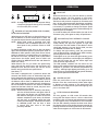 4
4
-
 5
5
-
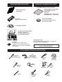 6
6
-
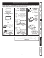 7
7
-
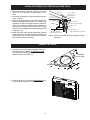 8
8
-
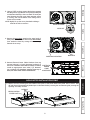 9
9
-
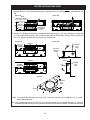 10
10
-
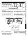 11
11
-
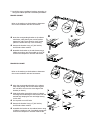 12
12
-
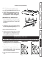 13
13
-
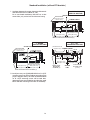 14
14
-
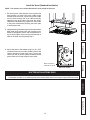 15
15
-
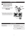 16
16
-
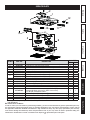 17
17
-
 18
18
-
 19
19
-
 20
20
-
 21
21
-
 22
22
-
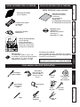 23
23
-
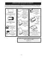 24
24
-
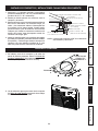 25
25
-
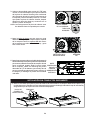 26
26
-
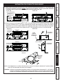 27
27
-
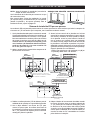 28
28
-
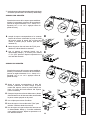 29
29
-
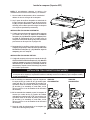 30
30
-
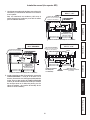 31
31
-
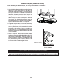 32
32
-
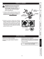 33
33
-
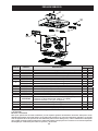 34
34
-
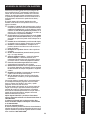 35
35
-
 36
36


Kenmore Elite 51403 Guía de instalación
- Categoría
- Campanas de cocina
- Tipo
- Guía de instalación
En otros idiomas
- français: Kenmore Elite 51403 Guide d'installation
- English: Kenmore Elite 51403 Installation guide