ATEN CM1164A Guía de inicio rápido
- Categoría
- Conmutadores KVM
- Tipo
- Guía de inicio rápido

1
4
2
5
6
7
8
1 2
3 4
PC1PC2PC3PC4
3
7
1
2 2
3
4
5 6 7 8 9
32
4
1
5
6
A
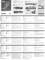
Hardware Review
Front View
1
KVM Status Panel
2
Port Selection Pushbuttons
3
Mode Selection Pushbutton
4
OSD (Esc)
5
Selection button
6
Direction/Function buttons
7
Console Audio Ports
8
USB 2.0 Peripheral Port
9
I
R Receiver
1
Plug your USB keyboard and USB mouse into the USB Console
Ports located on the unit’s rear panel.
2
Plug your DVI display into the Console DVI-D Single Link Port
located on the unit’s rear panel.
3
If you are using an IP phone headset or separate microphone and
speakers, plug them into the analog audio ports on the unit’s front
panel. These audio ports have priority over those on the rear panel.
4
If you are using separate speakers and microphone, plug them into
the console analog audio ports on the unit’s rear panel.
5
Using the DVI KVM cable set, plug the DVI-D Single Link cable connector
and the accompanying USB and audio connectors into their corresponding
sockets on the rear of the switch.
6
At the other end of the cable, plug the DVI and USB cables into their
respective ports on the computer(s) that is(are) the source of DVI
content.
7
Plug your USB peripherals into the type A sockets (one easy-access
port is located on the front for portable devices; the second is
located on the rear).
8
Connect the power cord to the switch and to an AC power source.
9
Power on the displays and the computers/devices.
Note: The recommended power-on sequence is Port 1–Port 2–Port
3–Port 4.
Operation
There are several convenient methods you can use to operate the CM1164A
and display the source device(s) connected to it.
Manual Switching
Use the pushbuttons (1 to 4) located on the front panel of the CM1164A to
switch between ports.
IR Remote Control
To select a source device with the remote control, press the numbered button
(1 to 4) that corresponds to the port to which it is connected.
© Copyright 2019 ATEN
®
International Co., Ltd.
ATEN and the ATEN logo are trademarks of ATEN International Co., Ltd. All rights reserved. All
other trademarks are the property of their respective owners.
Part No. PAPE-1223-771G Printing Date: 05/2019
4-Port USB DVI Multi-View KVMP
™
Switch
Quick Start Guide
CM1164A
CM1164A 4-Port USB DVI Multi-View KVMP™ Switch
www.aten.com
Commutateur KVMP™ multi-vues DVI USB 4 ports CM1164A
www.aten.com
4-Port-USB-DVI-Mehrfachansicht-KVMP™-Switch CM1164A
www.aten.com
Conmutador KVMP™ DVI USB Multipantalla de 4 puertos CM1164A
www.aten.com
CM1164A 4-портовый коммутатор USB DVI Multi-View KVMP™
www.aten.com
Switch KVMP™ Multi-View DVI USB 4 porte CM1164A
www.aten.com
Keyboard Hotkeys
You can switch ports using the console keyboard by fi rst activating the Hotkey
Setting Mode (HSM).
Hotkey Setting Mode
Invoking HSM
To invoke HSM do the following:
1. Press and hold down the Num Lock key
2. Press and release the minus key
3. Release the Num Lock key
Additionally, you can activate the On-Screen Display (OSD) and confi gure the
CM1164A – including assigning the KVM, Audio and USB Link focus for each
port, setting up channels, selecting the Display mode, and so on. To turn on
the OSD screen, press the OSD pushbutton on the front panel of the device, or
the OSD button in the remote control. You can use the remote control or the
console mouse to navigate the OSD menu.
Support and Documentation Notice
All information, documentation, fi rmware,
software utilities, and specifi cations
contained in this package are subject to
change without prior notifi cation by
the manufacturer.
To reduce the environmental impact of our
products, ATEN documentation and software
can be found online at
http://www.aten.com/download/
Technical Support
www.aten.com/support
이 기기는 업무용(A급) 전자파적합기기로서 판매자 또는
사용자는 이 점을 주의하시기 바라며, 가정외의 지역에
서 사용하는 것을 목적으로 합니다.
Scan for
more information
EMC Information
FEDERAL COMMUNICATIONS COMMISSION INTERFERENCE
STATEMENT:
This equipment has been tested and found to comply with the
limits for a Class A digital device, pursuant to Part 15 of the FCC
Rules. These limits are designed to provide reasonable protection
against harmful interference when the equipment is operated
in a commercial environment. This equipment generates, uses,
and can radiate radio frequency energy and, if not installed
and used in accordance with the instruction manual, may cause
harmful interference to radio communications. Operation of
this equipment in a residential area is likely to cause harmful
interference in which case the user will be required to correct the
interference at his own expense.
FCC Caution: Any changes or modifi cations not expressly
approved by the party responsible for compliance could void the
user's authority to operate this equipment.
Warning: Operation of this equipment in a residential
environment could cause radio interference.
This device complies with Part 15 of the FCC Rules. Operation
is subject to the following two conditions: (1) this device may
not cause harmful interference, and (2) this device must accept
any interference received, including interference that may cause
undesired operation.
A
Description du matériel
Vue avant
1
Voyants d'état USB
2
Boutons de sélection de port
3
Bouton de sélection du mode
4
Bouton OSD (Échap)
5
Bouton de sélection
6
Boutons de direction/fonction
7
Ports audio de console
8
Port périphérique USB 2.0
9
Récepteur infrarouge
A
Hardwareübersicht
Vorderseitige Ansicht
1
USB-Statusanzeigefeld
2
Portauswahl-Drucktasten
3
Betriebsmodus-Auswahltaste
4
OSD-Taste (Esc)
5
Auswahltaste
6
Richtungs-/Funktionstasten
7
Konsol-Audioports
8
USB 2.0-Port für Peripheriegeräte
9
Infrarot-Empfänger
A
Presentación del hardware
Vista frontal
1
Panel de estado USB
2
Botones de selección de puerto
3
Botón de selección de modo
4
Botón OSD (Esc)
5
Botón de selección
6
Botones de dirección/función
7
Puertos de consola de audio
8
Puerto USB 2.0 para periféricos
9
Receptor de infrarrojos
A
Hardware
Vista anteriore
1
Pannello di stato USB
2
Pulsanti di selezione della porta
3
Pulsante di selezione della modalità
4
Pulsante OSD (Esc)
5
Pulsante di selezione
6
Pulsante direzioni/funzioni
7
Porte di collegamento audio alla
console
8
Porta USB 2.0 periferica
9
Ricevitore ad infrarossi
1
Branchez les câbles de votre clavier USB et de votre souris USB sur les ports
de console USB situés à l'arrière de l'appareil.
2
Branchez votre écran DVI sur le port de console DVI-D Single Link situé sur
le panneau arrière de l’appareil.
3
Si vous utilisez un casque pour téléphonie IP ou un microphone et des haut-
parleurs à part, branchez-les sur les ports audio analogiques situés sur le
panneau avant de l'appareil. Ces ports audio ont la priorité sur ceux situés
sur le panneau arrière.
4
Si vous utilisez des haut-parleurs et microphone externes, branchez-les sur
les ports audio analogiques de console situés à l'arrière de l'appareil.
5
À l'aide du jeu de câbles KVM DVI, branchez le connecteur du câble DVI-D
Single Link ainsi que les connecteurs USB et audio associés sur les prises
correspondantes à l'arrière du commutateur.
6
A l’autre extrémité du câble, branchez les connecteurs DVI et USB dans les
ports correspondants de l’ordinateur (des ordinateurs) constituant la source
du contenu DVI.
7
Branchez vos périphériques USB sur les prises de type A (l'une est située
à l'avant pour en faciliter l’accès pour les appareils portables, tandis que
l'autre est à l'arrière).
2
Verbinden Sie Ihr DVI-Anzeigegerät mit dem DVI-D-Anschluss (Single Link)
auf der Geräterückseite.
3
Wenn Sie ein Headset für VoIP-Telefonie oder ein externes Mikrofon und
externe Lautsprecher verwenden, schließen Sie diese an die analogen
Audioports auf der Gerätevorderseite an. Diese Audioanschlüsse erhalten
Priorität gegenüber den Anschlüssen der Geräterückseite.
4
Wenn Sie separate Lautsprecher und ein externes Mikrofon verwenden,
schließen Sie diese an die analogen Audioports auf der Geräterückseite an.
5
Verbinden Sie die DVI-D- (Single Link) und die USB- und Audio-Stecker des
DVI-KVM-Kabelsets mit den betreffenden Buchsen auf der Rückseite des
Switches.
6
Verbinden Sie am anderen Kabelende die DVI- und USB-Kabel mit den
geeigneten Buchsen des Computers bzw. der Computer, die als DVI-
Signalquelle verwendet werden sollen.
7
Verbinden Sie Ihre USB-Geräte mit den Typ-A-Anschlussbuchsen (die eine
befi ndet sich auf der Gerätevorderseite, die andere auf der -rückseite).
8
Schließen Sie das Netzkabel an den Switch und an eine geeignete
Stromquelle an.
9
Schalten Sie die Displays und die Computer bzw. Geräte ein.
1
Conecte el teclado USB y el mouse USB a los puertos de consola USB
ubicados en el panel posterior del equipo.
2
Conecte su pantalla DVI al puerto de consola DVI-D Single Link ubicado en
el panel posterior de la unidad.
3
Si emplea unos cascos para telefonía sobre IP o unos altavoces y micrófono
externos, conéctelos a los puertos de audio analógicos ubicados en el panel
anterior de la unidad. Estos puertos de audio tienen prioridad sobre los del
panel posterior.
4
Si emplea altavoces y micrófono externos, conéctelos a los puertos de audio
analógicos de consola ubicados en el panel posterior de la unidad.
5
Mediante el juego de cables KVM HDMI incluido, enchufe los conectores
del cable DVI-D Single Link y demás conectores USB y audio a los puertos
correspondientes ubicados en la parte posterior del conmutador.
6
En el otro extremo del cable, enchufe los cables DVI y USB en los puertos
correspondientes de las computadoras que desee emplear como fuente de
los contenidos DVI.
7
Conecte sus periféricos USB a los puertos de tipo A (uno de fácil acceso
ubicado en el panel anterior y el segundo en el panel posterior del equipo).
1
Collegare la tastiera ed il mouse USB alle porte USB della console poste sul
pannello posteriore del dispositivo.
2
Collegare il monitor DVI alla porta DVI-D Single Link della console posta sul
pannello posteriore del dispositivo.
3
Se si utilizzano un set di cuffi a e microfono per IP phone o microfono e
altoparlanti separati, collegarli alle porte audio analogiche sul pannello
anteriore del dispositivo. Queste porte audio hanno la priorità su quelle del
pannello posteriore.
4
Se si utilizzano degli altoparlanti e dei microfoni esterni, collegarli alle porte
audio analogiche console poste sul pannello posteriore del dispositivo.
5
Quando si utilizza il cavo DVI KVM, collegare il connettore del cavo DVI-D
Single Link e i connettori audio e USB che lo accompagnano alle relative
prese sul retro dello switch.
6
All’altra estremità del cavo, inserire i cavi DVI e USB nelle rispettive porte
sul/sui computer da cui provengono i contenuti DVI.
7
Collegare le periferiche USB alle prese di tipo A (una porta con l’accesso
facilitato si trova sul lato anteriore, per i dispositivi portatili; la seconda è
situata sul lato posteriore).
8
Branchez le cordon d’alimentation au commutateur et à une source
d’alimentation CA.
9
Mettez sous tension les écrans et les ordinateurs/appareils.
Remarque : pour la mise sous tension, il est recommandé de respecter l’ordre
suivant : port 1–port 2–port 3–port 4.
Fonctionnement
Vous pouvez utiliser diverses méthodes pratiques pour faire fonctionner le
CM1164A et affi cher le ou les périphérique(s) source connecté(s).
Commutation manuelle
Utilisez les boutons poussoirs (1 à 4) situés sur le panneau avant du CM1164A
pour commuter entre les ports.
Télécommande infrarouge
Pour sélectionner un périphérique source à l’aide de la télécommande, appuyez
sur la touche numérotée (1 à 4) correspondant au port auquel il est connecté.
Hinweis: Wir empfehlen Ihnen, die Geräte der Reihe nach einzuschalten,
also z.B. Port 1–Port 2–Port 3–Port 4.
Bedienung
Sie können den CM1164A auf verschiedene Arten bedienen und die
angeschlossene(n) Signalquelle(n) anzeigen.
Manuelle Portumschaltung
Verwenden Sie die Drucktasten (1 bis 4) auf der Vorderseite des CM1164A, um
zwischen den Ports umzuschalten.
Infrarot-Fernbedienung
Um eine Signalquelle über die Fernbedienung auszuwählen, drücken Sie
die Zifferntaste (1 bis 4) mit der Nummer, die den Port des angeschlossenen
Gerätes darstellt.
Hotkey-Tasten
Sie können auch zwischen den Ports über die Konsoltastatur umschalten. Dazu
müssen Sie zunächst den Hotkey-Modus aktivieren.
8
Conecte el cable de alimentación al conmutador y a una toma eléctrica.
9
Encienda las pantallas y las computadoras o dispositivos.
Nota: La secuencia de encendido recomendada es Puerto 1–Puerto 2–
Puerto 3–Puerto 4.
Funcionamiento
Puede manejar el CM1164A de diferentes maneras muy prácticas a la hora de
visualizar la imagen de los dispositivos fuente de señal que tiene conectados.
Conmutación manual
Utilice los pulsadores (1 al 4) del panel frontal del CM1164A para conmutar
entre los puertos.
Mando a distancia por infrarrojos
Para seleccionar un dispositivo fuente con el mando a distancia, pulse la tecla
numérica (1 a 4) que corresponde al número del puerto donde tiene conectado
el dispositivo en cuestión.
8
Collegare il cavo d’alimentazione allo switch e a una fonte di corrente CA
adatta.
9
Accendere gli schermi e i computer/dispositivi.
Nota: la sequenza di accensione consigliata è Porta 1 – Porta 2 – Porta 3 –
Porta 4.
Funzionamento
Sono disponibili diversi comodi metodi per utilizzare il CM1164A e visualizzare
i dispositivi sorgente a esso connessi.
Commutazione manuale
Utilizzare i pulsanti (da 1 a 4) del pannello anteriore del CM1164A per passare
da una porta all’altra.
Telecomando a infrarossi
Per selezionare un dispositivo sorgente tramite telecomando, premere il
pulsante numerato (da 1 a 4) corrispondente alla porta a cui è collegato il
dispositivo.
Raccourcis clavier
Pour commuter entre les ports à l’aide du clavier de la console, activez d’abord
le mode de raccourcis clavier (HSM)
Mode de raccourcis clavier
Activation du mode de raccourcis clavier
Pour activer le mode de raccourcis clavier, procédez comme suit :
1. Appuyez sur la touche Verr num et maintenez-la enfoncée.
2. Appuyez sur la touche Moins [-], puis relâchez-la.
3. Relâchez la touche Verr num.
De plus, vous pouvez activer l’affi chage à l’écran (OSD) et confi gurer le
CM1164A, à savoir attribuer les contrôles KVM, Audio et USB Link à chaque
port, paramétrer les canaux, sélectionner le mode d’affi chage, etc. Pour activer
l’affi chage à l’écran, appuyez sur le bouton poussoir OSD situé sur le panneau
avant du périphérique ou utilisez la touche OSD de la télécommande. Pour
naviguer dans le menu OSD, vous pouvez utiliser la télécommande ou la souris
de la console.
Hotkey-Einrichtung
Hotkey-Modus (HSM) aktivieren
Gehen Sie zur Aktivierung des HSM folgendermaßen vor:
1. Halten Sie die Taste Num gedrückt.
2. Drücken Sie die Taste Minus, und lassen Sie sie los.
3. Lassen Sie die Taste Num los.
Weiterhin können Sie das OSD-Bildschirmmenü des CM1164A aufrufen
und ihn hier konfi gurieren. Dabei können Sie die KVM, Audio und USB-
Signale einem Port zuordnen, Kanäle einrichten, den Anzeigemodus
wählen usw. . Um das OSD-Bildschirmmenü einzublenden, drücken Sie die
OSD-Taste am vorderseitigen Bedienfeld des Gerätes oder die OSD-Taste
auf der Fernbedienung. Im OSD-Bildschirmmenü können Sie mithilfe der
Fernbedienung oder der Konsolmaus navigieren.
Teclas de acceso directo
Puede conmutar entre los puertos con el teclado de consola. Para ello, primero
tendrá que activar el modo de teclas de acceso directo.
Modo de teclas de acceso directo
Activar el modo de teclas de acceso directo
Para activar el modo de teclas de acceso directo:
1. Mantenga pulsada la tecla Bloq Num.
2. Pulse la tecla Menos [-] y suéltela.
3. Suelte la tecla Bloq Num.
Además, podrá activar el menú en pantalla (OSD) y confi gurar el CM1164A.
Ello incluye funciones tales como la asignación del control KVM, de las señales
de audio y USB a puertos individuales, el ajuste de canales, la selección del
modo de pantalla etc. Para activar el menú en pantalla, pulse el botón OSD
del panel frontal del dispositivo o el botón OSD del mando a distancia. Puede
emplear el mando a distancia o el mouse de la consola para navegar en el
menú OSD.
Tasti di scelta rapida
È possibile cambiare porta tramite la tastiera della console attivando prima la
modalità d’impostazione dei tasti di scelta rapida (HSM)
Modalità d’impostazione dei tasti di scelta rapida (HSM)
Richiamare HSM
Per attivare HSM, procedere come segue:
1. Premere e tenere premuto il tasto Bloc Num.
2. Premere e rilasciare il tasto ‘meno’
3. Rilasciare il tasto Bloc Num
Inoltre, è possibile attivare l’OSD e confi gurare il CM1164A, compresa
l’assegnazione di KVM, audio e collegamento USB per ciascuna porta,
l’impostazione dei canali, la selezione della modalità di visualizzazione ecc. Per
attivare l’OSD, premere il tasto OSD sul panello anteriore del dispositivo o due
volte il pulsante OSD sul telecomando. Per spostarsi nel menu OSD, è possibile
utilizzare il telecomando o il mouse della console.
A
Обзор оборудования
Вид спереди
1
Панель состояния USB
2
Кнопки выбора порта
3
Кнопка выбора режима работы
4
Кнопка вызова/закрывания экранного
меню
5
Кнопка выбора
6
Кнопки выбора направления/функции
7
Звуковые порты консоли
8
Порт USB 2.0 для периферийных
устройств
9
ИК-приемник
(номера на схеме соответствуют шагам установки) и выполните следующие
действия.
1
Подключите клавиатуру и мышь USB к портам USB консоли,
расположенным на задней панели устройства.
2
Подключите устройство отображения DVI к порту одноканальный DVI-D
консоли, расположенному на задней панели устройства.
3
Если используется гарнитура IP-связи либо отдельные микрофон и
динамики, подключите их к аналоговым аудио портам на лицевой панели
устройства. Эти аудио порты имеют более высокий приоритет, чем те,
что расположены на задней панели.
4
Если используются отдельные динамики и микрофон, подключите их к
аналоговым аудио портам консоли на задней панели устройства.
5
Используя комплект кабелей DVI KVM, подключите разъем
одноканального DVI-D и идущие вместе с ним разъемы USB и аудио к
соответствующим портам на задней панели переключателя.
6
С другой стороны кабеля подключите разъемы DVI и USB к
соответствующим портам компьютера(ов), являющегося источником DVI-
содержимого.
7
Подключите периферийные устройства USB к портам USB типа А (один
порт быстрого доступа расположен на лицевой панели и предназначен
для портативных устройств; другой расположен на задней панели).
8
Подключите шнур питания к переключателю и источнику переменного
тока.
9
Включите устройства отображения и компьютеры/устройства.
Примечание. Рекомендуется следующая последовательность включения:
порт 1 – порт 2 – порт 3 – порт 4.
Работа
Имеется несколько удобных способов работы с CM1164A и отображения
содержимого с подключенных к нему устройств-источников.
Ручное переключение
Для переключения между портами используйте кнопки (1-4) на лицевой
панели CM1164A.
ИК-пульт ДУ
Чтобы выбрать устройство-источник с помощью пульта ДУ, нажмите
кнопку с цифрой (1-4), соответствующей порту, к которому подключено это
устройство.
Горячие клавиши на клавиатуре
Для переключения портов с помощью клавиатуры консоли сначала
активируйте режим настройки горячих клавиш
Режим настройки горячих клавиш
Вызов режима настройки горячих клавиш
Для вызова режима настройки горячих клавиш выполните следующие
действия.
1. Нажмите и удерживайте клавишу Num Lock.
2. Нажмите и отпустите клавишу с минусом.
3. Отпустите клавишу Num Lock.
Кроме того, можно вызвать экранное меню (OSD) и задать конфигурацию
CM1164A – включая назначение фокуса KVM, аудио и USB каждому порту,
задание каналов, выбор режима отображения и т. д. Чтобы включить
экранное меню, нажмите кнопку OSD на лицевой панели устройства либо
кнопку OSD на пульте ДУ. Для перемещения по экранному меню можно
использовать пульт ДУ или мышь консоли.
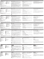
B
Package Contents
1 CM1164A 4-Port USB DVI Multi-View KVMP™ Switch
4 KVM Cables (DVI-D, USB, Audio)
1 Power Cord
1 IR Remote Control
1 Rack Mount Kit
1 User Instructions
Hardware Installation
A
Hardware Review
Вид сзади
1
Входные/выходные порты
управления гирляндным
подключением
2
Область портов консоли
3
Область DVI KVM
4
Разъем питания/выключатель
питания
5
Клемма заземления
6
ИК-приемник (дополнительно)
B
Установка оборудования
Подключение кабелей
Перед началом установки CM1164A ознакомьтесь со схемой установки
Rear View
1
Daisy Chain Control In/Out Ports
2
Console Port Section
3
DVI KVM Section
4
Power Socket/Power Switch
5
Grounding Terminal
6
IR Receiver (Extension)
Vue arrière
1
Ports d’entrée/sortie de contrôle
en chaîne
2
Section des ports de console
3
Section KVM DVI
4
Connecteur d’alimentation/
Interrupteur d’alimentation
5
Prise de terre
6
Récepteur infrarouge (rallonge)
Rückseitige Ansicht
1
Ein- und Ausgänge für
Reihenschaltung
2
Konsolportabschnitt
3
DVI-KVM-Abschnitt
4
Kaltgerätebuchse/Netzschalter
5
Erdungsanschluss
6
nfrarot-Empfänger (Erweiterung)
Vista posterior
1
Puertos de entrada/salida para
conexión en margarita
2
Sección de puertos de consola
3
Sección KVM DVI
4
Entrada e interruptor de
alimentación
5
Toma de tierra
6
Receptor de infrarrojos (extensión)
Vista posteriore
1
Porte d’entrata/uscita controllo a
cascata
2
Sezione della porta di
collegamento alla console
3
Sezione DVI KVM
4
Presa/Interruttore d’alimentazione
5
Terminale di messa a terra
6
Ricevitore ad infrarossi
(estensione)
B
Hardware Installation
Cable Connection
To set up your CM1164A installation, refer to the installation diagram
(the numbers in the diagrams correspond to the steps, above), and do the
following:
B
Installation du matériel
Branchement des câbles
Pour procéder à l'installation de votre CM1164A, reportez-vous au schéma
d'installation (les numéros du schéma correspondent aux étapes à suivre, voir
ci-dessus) et procédez comme suit :
B
Hardware installieren
Kabelverbindung
Zur Installation des CM1164A, siehe das Installationsdiagramm (die Nummern
im Diagramm entsprechen der Reihenfolge), und gehen Sie wie folgt vor:
1
Verbinden Sie Ihre USB-Tastatur und USB-Maus mit den USB-
Konsolanschlüssen auf der Rückseite des Gerätes.
B
Instalar el hardware
Conexión de cables
Para instalar su CM1164A, véase el diagrama de instalación (los números del
diagrama corresponden a las diferentes etapas a seguir) y proceda como se
indica a continuación:
B
Installazione dell’hardware
Connessione dei cavi
Per installare il CM1164A, fare riferimento all’illustrazione (i numeri nelle
illustrazioni corrispondono alle fasi) e procedere come segue:
Front View
Rear View
To prevent damage to your installation from power
surges or static electricity, it is important that all
connected devices are properly grounded.
La página se está cargando ...
Transcripción de documentos
Package Contents B 1 CM1164A 4-Port USB DVI Multi-View KVMP™ Switch 4 KVM Cables (DVI-D, USB, Audio) 1 Power Cord 1 IR Remote Control 1 Rack Mount Kit 1 User Instructions Support and Documentation Notice Hardware Installation 7 3 A Technical Support Hardware Review www.aten.com/support 5 Front View 7 4 1 PC4 PC3 PC2 EMC Information 3 2 4-Port USB DVI Multi-View KVMP™ Switch Quick Start Guide 2 5 6 7 8 8 5 2 1 FEDERAL COMMUNICATIONS COMMISSION INTERFERENCE STATEMENT: This equipment has been tested and found to comply with the limits for a Class A digital device, pursuant to Part 15 of the FCC Rules. These limits are designed to provide reasonable protection against harmful interference when the equipment is operated in a commercial environment. This equipment generates, uses, and can radiate radio frequency energy and, if not installed and used in accordance with the instruction manual, may cause harmful interference to radio communications. Operation of this equipment in a residential area is likely to cause harmful interference in which case the user will be required to correct the interference at his own expense. FCC Caution: Any changes or modifications not expressly approved by the party responsible for compliance could void the user's authority to operate this equipment. Warning: Operation of this equipment in a residential environment could cause radio interference. 9 1 Rear View © Copyright 2019 3 4 International Co., Ltd. 1 3 2 4 2 ATEN and the ATEN logo are trademarks of ATEN International Co., Ltd. All rights reserved. All 6 other trademarks are the property of their respective owners. Part No. PAPE-1223-771G Scan for more information PC1 CM1164A ATEN® All information, documentation, firmware, software utilities, and specifications contained in this package are subject to change without prior notification by the manufacturer. To reduce the environmental impact of our products, ATEN documentation and software can be found online at http://www.aten.com/download/ This device complies with Part 15 of the FCC Rules. Operation is subject to the following two conditions: (1) this device may not cause harmful interference, and (2) this device must accept any interference received, including interference that may cause undesired operation. Printing Date: 05/2019 4 6 To prevent damage to your installation from power surges or static electricity, it is important that all connected devices are properly grounded. 이 기기는 업무용(A급) 전자파적합기기로서 판매자 또는 사용자는 이 점을 주의하시기 바라며, 가정외의 지역에 서 사용하는 것을 목적으로 합니다. CM1164A 4-Port USB DVI Multi-View KVMP™ Switch A Hardware Front View 1 2 3 4 5 6 7 8 9 Review www.aten.com 1 Rear View KVM Status Panel Port Selection Pushbuttons Mode Selection Pushbutton OSD (Esc) Selection button Direction/Function buttons Console Audio Ports USB 2.0 Peripheral Port IR Receiver 1 2 3 4 5 6 Daisy Chain Control In/Out Ports Console Port Section DVI KVM Section Power Socket/Power Switch Grounding Terminal IR Receiver (Extension) 2 3 4 5 6 B Hardware Installation Cable Connection To set up your CM1164A installation, refer to the installation diagram (the numbers in the diagrams correspond to the steps, above), and do the following: 7 Plug your USB keyboard and USB mouse into the USB Console Ports located on the unit’s rear panel. Plug your DVI display into the Console DVI-D Single Link Port located on the unit’s rear panel. If you are using an IP phone headset or separate microphone and speakers, plug them into the analog audio ports on the unit’s front panel. These audio ports have priority over those on the rear panel. If you are using separate speakers and microphone, plug them into the console analog audio ports on the unit’s rear panel. Using the DVI KVM cable set, plug the DVI-D Single Link cable connector and the accompanying USB and audio connectors into their corresponding sockets on the rear of the switch. At the other end of the cable, plug the DVI and USB cables into their respective ports on the computer(s) that is(are) the source of DVI content. Plug your USB peripherals into the type A sockets (one easy-access port is located on the front for portable devices; the second is located on the rear). 8 9 Connect the power cord to the switch and to an AC power source. Power on the displays and the computers/devices. Note: The recommended power-on sequence is Port 1–Port 2–Port 3–Port 4. Operation There are several convenient methods you can use to operate the CM1164A and display the source device(s) connected to it. Manual Switching Use the pushbuttons (1 to 4) located on the front panel of the CM1164A to switch between ports. IR Remote Control To select a source device with the remote control, press the numbered button (1 to 4) that corresponds to the port to which it is connected. Keyboard Hotkeys You can switch ports using the console keyboard by first activating the Hotkey Setting Mode (HSM). Hotkey Setting Mode Invoking HSM To invoke HSM do the following: 1. Press and hold down the Num Lock key 2. Press and release the minus key 3. Release the Num Lock key Additionally, you can activate the On-Screen Display (OSD) and configure the CM1164A – including assigning the KVM, Audio and USB Link focus for each port, setting up channels, selecting the Display mode, and so on. To turn on the OSD screen, press the OSD pushbutton on the front panel of the device, or the OSD button in the remote control. You can use the remote control or the console mouse to navigate the OSD menu. Commutateur KVMP™ multi-vues DVI USB 4 ports CM1164A A Description Vue avant 1 2 3 4 5 6 7 8 9 du matériel 1 Vue arrière Voyants d'état USB Boutons de sélection de port Bouton de sélection du mode Bouton OSD (Échap) Bouton de sélection Boutons de direction/fonction Ports audio de console Port périphérique USB 2.0 Récepteur infrarouge www.aten.com 1 2 3 4 5 6 Ports d’entrée/sortie de contrôle en chaîne Section des ports de console Section KVM DVI Connecteur d’alimentation/ Interrupteur d’alimentation Prise de terre Récepteur infrarouge (rallonge) B Installation du matériel Branchement des câbles 2 3 4 5 6 Pour procéder à l'installation de votre CM1164A, reportez-vous au schéma d'installation (les numéros du schéma correspondent aux étapes à suivre, voir ci-dessus) et procédez comme suit : 7 Branchez les câbles de votre clavier USB et de votre souris USB sur les ports de console USB situés à l'arrière de l'appareil. Branchez votre écran DVI sur le port de console DVI-D Single Link situé sur le panneau arrière de l’appareil. Si vous utilisez un casque pour téléphonie IP ou un microphone et des hautparleurs à part, branchez-les sur les ports audio analogiques situés sur le panneau avant de l'appareil. Ces ports audio ont la priorité sur ceux situés sur le panneau arrière. Si vous utilisez des haut-parleurs et microphone externes, branchez-les sur les ports audio analogiques de console situés à l'arrière de l'appareil. À l'aide du jeu de câbles KVM DVI, branchez le connecteur du câble DVI-D Single Link ainsi que les connecteurs USB et audio associés sur les prises correspondantes à l'arrière du commutateur. A l’autre extrémité du câble, branchez les connecteurs DVI et USB dans les ports correspondants de l’ordinateur (des ordinateurs) constituant la source du contenu DVI. Branchez vos périphériques USB sur les prises de type A (l'une est située à l'avant pour en faciliter l’accès pour les appareils portables, tandis que l'autre est à l'arrière). Branchez le cordon d’alimentation au commutateur et à une source d’alimentation CA. 9 Mettez sous tension les écrans et les ordinateurs/appareils. Remarque : pour la mise sous tension, il est recommandé de respecter l’ordre suivant : port 1–port 2–port 3–port 4. Raccourcis clavier Fonctionnement Activation du mode de raccourcis clavier Pour activer le mode de raccourcis clavier, procédez comme suit : 1. Appuyez sur la touche Verr num et maintenez-la enfoncée. 2. Appuyez sur la touche Moins [-], puis relâchez-la. 3. Relâchez la touche Verr num. 8 Vous pouvez utiliser diverses méthodes pratiques pour faire fonctionner le CM1164A et afficher le ou les périphérique(s) source connecté(s). Commutation manuelle Utilisez les boutons poussoirs (1 à 4) situés sur le panneau avant du CM1164A pour commuter entre les ports. Télécommande infrarouge Pour sélectionner un périphérique source à l’aide de la télécommande, appuyez sur la touche numérotée (1 à 4) correspondant au port auquel il est connecté. Pour commuter entre les ports à l’aide du clavier de la console, activez d’abord le mode de raccourcis clavier (HSM) Mode de raccourcis clavier De plus, vous pouvez activer l’affichage à l’écran (OSD) et configurer le CM1164A, à savoir attribuer les contrôles KVM, Audio et USB Link à chaque port, paramétrer les canaux, sélectionner le mode d’affichage, etc. Pour activer l’affichage à l’écran, appuyez sur le bouton poussoir OSD situé sur le panneau avant du périphérique ou utilisez la touche OSD de la télécommande. Pour naviguer dans le menu OSD, vous pouvez utiliser la télécommande ou la souris de la console. www.aten.com 4-Port-USB-DVI-Mehrfachansicht-KVMP™-Switch CM1164A A Hardwareübersicht Vorderseitige Ansicht 1 2 3 4 5 6 7 8 9 USB-Statusanzeigefeld Portauswahl-Drucktasten Betriebsmodus-Auswahltaste OSD-Taste (Esc) Auswahltaste Richtungs-/Funktionstasten Konsol-Audioports USB 2.0-Port für Peripheriegeräte Infrarot-Empfänger 2 Rückseitige Ansicht 1 2 3 4 5 6 Ein- und Ausgänge für Reihenschaltung Konsolportabschnitt DVI-KVM-Abschnitt Kaltgerätebuchse/Netzschalter Erdungsanschluss nfrarot-Empfänger (Erweiterung) 3 4 5 6 B Hardware installieren Kabelverbindung 7 Zur Installation des CM1164A, siehe das Installationsdiagramm (die Nummern im Diagramm entsprechen der Reihenfolge), und gehen Sie wie folgt vor: 1 Verbinden Sie Ihre USB-Tastatur und USB-Maus mit den USBKonsolanschlüssen auf der Rückseite des Gerätes. 8 9 Verbinden Sie Ihr DVI-Anzeigegerät mit dem DVI-D-Anschluss (Single Link) auf der Geräterückseite. Wenn Sie ein Headset für VoIP-Telefonie oder ein externes Mikrofon und externe Lautsprecher verwenden, schließen Sie diese an die analogen Audioports auf der Gerätevorderseite an. Diese Audioanschlüsse erhalten Priorität gegenüber den Anschlüssen der Geräterückseite. Wenn Sie separate Lautsprecher und ein externes Mikrofon verwenden, schließen Sie diese an die analogen Audioports auf der Geräterückseite an. Verbinden Sie die DVI-D- (Single Link) und die USB- und Audio-Stecker des DVI-KVM-Kabelsets mit den betreffenden Buchsen auf der Rückseite des Switches. Verbinden Sie am anderen Kabelende die DVI- und USB-Kabel mit den geeigneten Buchsen des Computers bzw. der Computer, die als DVISignalquelle verwendet werden sollen. Verbinden Sie Ihre USB-Geräte mit den Typ-A-Anschlussbuchsen (die eine befindet sich auf der Gerätevorderseite, die andere auf der -rückseite). Schließen Sie das Netzkabel an den Switch und an eine geeignete Stromquelle an. Schalten Sie die Displays und die Computer bzw. Geräte ein. Hinweis: Wir empfehlen Ihnen, die Geräte der Reihe nach einzuschalten, also z.B. Port 1–Port 2–Port 3–Port 4. Bedienung Sie können den CM1164A auf verschiedene Arten bedienen und die angeschlossene(n) Signalquelle(n) anzeigen. Manuelle Portumschaltung Verwenden Sie die Drucktasten (1 bis 4) auf der Vorderseite des CM1164A, um zwischen den Ports umzuschalten. Infrarot-Fernbedienung Um eine Signalquelle über die Fernbedienung auszuwählen, drücken Sie die Zifferntaste (1 bis 4) mit der Nummer, die den Port des angeschlossenen Gerätes darstellt. Hotkey-Einrichtung Hotkey-Modus (HSM) aktivieren Gehen Sie zur Aktivierung des HSM folgendermaßen vor: 1. Halten Sie die Taste Num gedrückt. 2. Drücken Sie die Taste Minus, und lassen Sie sie los. 3. Lassen Sie die Taste Num los. Weiterhin können Sie das OSD-Bildschirmmenü des CM1164A aufrufen und ihn hier konfigurieren. Dabei können Sie die KVM, Audio und USBSignale einem Port zuordnen, Kanäle einrichten, den Anzeigemodus wählen usw. . Um das OSD-Bildschirmmenü einzublenden, drücken Sie die OSD-Taste am vorderseitigen Bedienfeld des Gerätes oder die OSD-Taste auf der Fernbedienung. Im OSD-Bildschirmmenü können Sie mithilfe der Fernbedienung oder der Konsolmaus navigieren. Hotkey-Tasten Sie können auch zwischen den Ports über die Konsoltastatur umschalten. Dazu müssen Sie zunächst den Hotkey-Modus aktivieren. Conmutador KVMP™ DVI USB Multipantalla de 4 puertos CM1164A A Presentación Vista frontal 1 2 3 4 5 6 7 8 9 del hardware Panel de estado USB Botones de selección de puerto Botón de selección de modo Botón OSD (Esc) Botón de selección Botones de dirección/función Puertos de consola de audio Puerto USB 2.0 para periféricos Receptor de infrarrojos 1 Vista posterior 1 2 3 4 5 6 www.aten.com Puertos de entrada/salida para conexión en margarita Sección de puertos de consola Sección KVM DVI Entrada e interruptor de alimentación Toma de tierra Receptor de infrarrojos (extensión) B Instalar el hardware Conexión de cables 2 3 4 5 6 Para instalar su CM1164A, véase el diagrama de instalación (los números del diagrama corresponden a las diferentes etapas a seguir) y proceda como se indica a continuación: 7 Conecte el teclado USB y el mouse USB a los puertos de consola USB ubicados en el panel posterior del equipo. Conecte su pantalla DVI al puerto de consola DVI-D Single Link ubicado en el panel posterior de la unidad. Si emplea unos cascos para telefonía sobre IP o unos altavoces y micrófono externos, conéctelos a los puertos de audio analógicos ubicados en el panel anterior de la unidad. Estos puertos de audio tienen prioridad sobre los del panel posterior. Si emplea altavoces y micrófono externos, conéctelos a los puertos de audio analógicos de consola ubicados en el panel posterior de la unidad. Mediante el juego de cables KVM HDMI incluido, enchufe los conectores del cable DVI-D Single Link y demás conectores USB y audio a los puertos correspondientes ubicados en la parte posterior del conmutador. En el otro extremo del cable, enchufe los cables DVI y USB en los puertos correspondientes de las computadoras que desee emplear como fuente de los contenidos DVI. Conecte sus periféricos USB a los puertos de tipo A (uno de fácil acceso ubicado en el panel anterior y el segundo en el panel posterior del equipo). 8 9 Conecte el cable de alimentación al conmutador y a una toma eléctrica. Encienda las pantallas y las computadoras o dispositivos. Nota: La secuencia de encendido recomendada es Puerto 1–Puerto 2– Puerto 3–Puerto 4. Funcionamiento Puede manejar el CM1164A de diferentes maneras muy prácticas a la hora de visualizar la imagen de los dispositivos fuente de señal que tiene conectados. Conmutación manual Utilice los pulsadores (1 al 4) del panel frontal del CM1164A para conmutar entre los puertos. Mando a distancia por infrarrojos Para seleccionar un dispositivo fuente con el mando a distancia, pulse la tecla numérica (1 a 4) que corresponde al número del puerto donde tiene conectado el dispositivo en cuestión. Teclas de acceso directo Puede conmutar entre los puertos con el teclado de consola. Para ello, primero tendrá que activar el modo de teclas de acceso directo. Modo de teclas de acceso directo Activar el modo de teclas de acceso directo Para activar el modo de teclas de acceso directo: 1. Mantenga pulsada la tecla Bloq Num. 2. Pulse la tecla Menos [-] y suéltela. 3. Suelte la tecla Bloq Num. Además, podrá activar el menú en pantalla (OSD) y configurar el CM1164A. Ello incluye funciones tales como la asignación del control KVM, de las señales de audio y USB a puertos individuales, el ajuste de canales, la selección del modo de pantalla etc. Para activar el menú en pantalla, pulse el botón OSD del panel frontal del dispositivo o el botón OSD del mando a distancia. Puede emplear el mando a distancia o el mouse de la consola para navegar en el menú OSD. Switch KVMP™ Multi-View DVI USB 4 porte CM1164A A Hardware Vista anteriore 1 2 3 4 5 6 7 8 9 Pannello di stato USB Pulsanti di selezione della porta Pulsante di selezione della modalità Pulsante OSD (Esc) Pulsante di selezione Pulsante direzioni/funzioni Porte di collegamento audio alla console Porta USB 2.0 periferica Ricevitore ad infrarossi www.aten.com 1 Vista posteriore 1 2 3 4 5 6 Porte d’entrata/uscita controllo a cascata Sezione della porta di collegamento alla console Sezione DVI KVM Presa/Interruttore d’alimentazione Terminale di messa a terra Ricevitore ad infrarossi (estensione) 2 3 4 5 6 B Installazione dell’hardware Connessione dei cavi 7 Per installare il CM1164A, fare riferimento all’illustrazione (i numeri nelle illustrazioni corrispondono alle fasi) e procedere come segue: Collegare la tastiera ed il mouse USB alle porte USB della console poste sul pannello posteriore del dispositivo. Collegare il monitor DVI alla porta DVI-D Single Link della console posta sul pannello posteriore del dispositivo. Se si utilizzano un set di cuffia e microfono per IP phone o microfono e altoparlanti separati, collegarli alle porte audio analogiche sul pannello anteriore del dispositivo. Queste porte audio hanno la priorità su quelle del pannello posteriore. Se si utilizzano degli altoparlanti e dei microfoni esterni, collegarli alle porte audio analogiche console poste sul pannello posteriore del dispositivo. Quando si utilizza il cavo DVI KVM, collegare il connettore del cavo DVI-D Single Link e i connettori audio e USB che lo accompagnano alle relative prese sul retro dello switch. All’altra estremità del cavo, inserire i cavi DVI e USB nelle rispettive porte sul/sui computer da cui provengono i contenuti DVI. Collegare le periferiche USB alle prese di tipo A (una porta con l’accesso facilitato si trova sul lato anteriore, per i dispositivi portatili; la seconda è situata sul lato posteriore). 8 9 Collegare il cavo d’alimentazione allo switch e a una fonte di corrente CA adatta. Accendere gli schermi e i computer/dispositivi. Nota: la sequenza di accensione consigliata è Porta 1 – Porta 2 – Porta 3 – Porta 4. Funzionamento Sono disponibili diversi comodi metodi per utilizzare il CM1164A e visualizzare i dispositivi sorgente a esso connessi. Commutazione manuale Utilizzare i pulsanti (da 1 a 4) del pannello anteriore del CM1164A per passare da una porta all’altra. Telecomando a infrarossi Per selezionare un dispositivo sorgente tramite telecomando, premere il pulsante numerato (da 1 a 4) corrispondente alla porta a cui è collegato il dispositivo. Tasti di scelta rapida È possibile cambiare porta tramite la tastiera della console attivando prima la modalità d’impostazione dei tasti di scelta rapida (HSM) Modalità d’impostazione dei tasti di scelta rapida (HSM) Richiamare HSM Per attivare HSM, procedere come segue: 1. Premere e tenere premuto il tasto Bloc Num. 2. Premere e rilasciare il tasto ‘meno’ 3. Rilasciare il tasto Bloc Num Inoltre, è possibile attivare l’OSD e configurare il CM1164A, compresa l’assegnazione di KVM, audio e collegamento USB per ciascuna porta, l’impostazione dei canali, la selezione della modalità di visualizzazione ecc. Per attivare l’OSD, premere il tasto OSD sul panello anteriore del dispositivo o due volte il pulsante OSD sul telecomando. Per spostarsi nel menu OSD, è possibile utilizzare il telecomando o il mouse della console. CM1164A 4-портовый коммутатор USB DVI Multi-View KVMP™ A Обзор оборудования Вид спереди 1 2 3 4 5 6 7 8 9 B Панель состояния USB Кнопки выбора порта Кнопка выбора режима работы Кнопка вызова/закрывания экранного меню Кнопка выбора Кнопки выбора направления/функции Звуковые порты консоли Порт USB 2.0 для периферийных устройств ИК-приемник Вид сзади 1 2 3 4 5 6 Входные/выходные порты управления гирляндным подключением Область портов консоли Область DVI KVM Разъем питания/выключатель питания Клемма заземления ИК-приемник (дополнительно) Установка оборудования Подключение кабелей Перед началом установки CM1164A ознакомьтесь со схемой установки www.aten.com (номера на схеме соответствуют шагам установки) и выполните следующие действия. 1 Подключите клавиатуру и мышь USB к портам USB консоли, расположенным на задней панели устройства. 2 Подключите устройство отображения DVI к порту одноканальный DVI-D консоли, расположенному на задней панели устройства. 3 Если используется гарнитура IP-связи либо отдельные микрофон и динамики, подключите их к аналоговым аудио портам на лицевой панели устройства. Эти аудио порты имеют более высокий приоритет, чем те, что расположены на задней панели. 4 Если используются отдельные динамики и микрофон, подключите их к аналоговым аудио портам консоли на задней панели устройства. 5 Используя комплект кабелей DVI KVM, подключите разъем одноканального DVI-D и идущие вместе с ним разъемы USB и аудио к соответствующим портам на задней панели переключателя. 6 С другой стороны кабеля подключите разъемы DVI и USB к соответствующим портам компьютера(ов), являющегося источником DVIсодержимого. 7 Подключите периферийные устройства USB к портам USB типа А (один порт быстрого доступа расположен на лицевой панели и предназначен для портативных устройств; другой расположен на задней панели). Подключите шнур питания к переключателю и источнику переменного тока. 9 Включите устройства отображения и компьютеры/устройства. Примечание. Рекомендуется следующая последовательность включения: порт 1 – порт 2 – порт 3 – порт 4. 8 Работа Имеется несколько удобных способов работы с CM1164A и отображения содержимого с подключенных к нему устройств-источников. Ручное переключение Для переключения между портами используйте кнопки (1-4) на лицевой панели CM1164A. ИК-пульт ДУ Чтобы выбрать устройство-источник с помощью пульта ДУ, нажмите кнопку с цифрой (1-4), соответствующей порту, к которому подключено это устройство. Горячие клавиши на клавиатуре Для переключения портов с помощью клавиатуры консоли сначала активируйте режим настройки горячих клавиш Режим настройки горячих клавиш Вызов режима настройки горячих клавиш Для вызова режима настройки горячих клавиш выполните следующие действия. 1. Нажмите и удерживайте клавишу Num Lock. 2. Нажмите и отпустите клавишу с минусом. 3. Отпустите клавишу Num Lock. Кроме того, можно вызвать экранное меню (OSD) и задать конфигурацию CM1164A – включая назначение фокуса KVM, аудио и USB каждому порту, задание каналов, выбор режима отображения и т. д. Чтобы включить экранное меню, нажмите кнопку OSD на лицевой панели устройства либо кнопку OSD на пульте ДУ. Для перемещения по экранному меню можно использовать пульт ДУ или мышь консоли.-
 1
1
-
 2
2


ATEN CM1164A Guía de inicio rápido
- Categoría
- Conmutadores KVM
- Tipo
- Guía de inicio rápido
En otros idiomas
- français: ATEN CM1164A Guide de démarrage rapide
- italiano: ATEN CM1164A Guida Rapida
- English: ATEN CM1164A Quick start guide
- Deutsch: ATEN CM1164A Schnellstartanleitung
- русский: ATEN CM1164A Инструкция по началу работы
- português: ATEN CM1164A Guia rápido
- polski: ATEN CM1164A Skrócona instrukcja obsługi
- 日本語: ATEN CM1164A クイックスタートガイド
- Türkçe: ATEN CM1164A Hızlı başlangıç Kılavuzu
Documentos relacionados
-
ATEN CM1164 Guía de inicio rápido
-
ATEN CM1284 Guía de inicio rápido
-
-
ATEN CS1642A Guía de inicio rápido
-
-
ATEN CM0264 Guía de inicio rápido
-
-
ATEN CS1922M Guía de inicio rápido
-
ATEN CS1944DP-AT-U Guía de inicio rápido
-