
1) TURN OFF POWER.
IMPORTANT: Before you start, NEVER attempt any work without
shutting off the electricity until the work is done.
a) Go to the main fuse, or circuit breaker, box in your home. Place
the main power switch in the “OFF” position.
b) Unscrew the fuse(s), or switch “OFF” the circuit breaker switch(s),
thatcontrolthepowertothextureorroomthatyouareworking
on.
c) Placethewallswitchinthe“OFF”position.Ifthexturetobe
replaced has a switch or pull chain, place those in the “OFF” position.
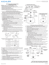
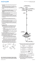
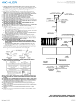
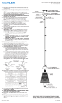
2) Thread hexnut onto threaded pipe so that approximately 5 threads are
exposed above hexnut. Thread that end of threaded pipe into mounting
strap. Thread second hexnut onto end of threaded pipe protruding from
back of mounting strap. Tighten both hexnuts against mounting strap
3) Attach mounting strap to outlet box. (Screws not provided)
4) Connect safety cable assembled to canopy to mounting bracket.
(Thiswillallowforxturetobesupportedwhilewireconnectionsare
made.)
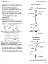
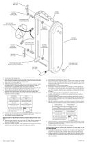
5) Grounding instructions: (See Illus. A or B).
A) Onxtureswheremountingstrapisprovidedwithaholeand
two raise dimples. Wrap ground wire from outlet box around
green ground screw, and thread into hole.
B) Onxtureswhereacuppedwasherisprovided.Attachground
wire from outlet box under cupped washer and green ground
screw, and thread into mounting strap.
Ifxtureisprovidedwithgroundwire.Connectxturegroundwireto
outlet box ground wire with wire connector. (Not provided.) After following
the above steps.
Never connect ground wire to black or white power supply wires.
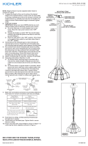
6) Make wire connections (connectors not provided.) Reference chart
below for correct connections and wire accordingly.
7) Pushxturetowall,carefullypassingthreadedpipethroughhole.
8) Securexturetowallusingthreadedcap.
INSTRUCTIONS FOR MOUNTING FIXTURE OUTDOORS AND/OR
IN WET LOCATIONS.
9) Mountingsurfaceshouldbeclean,dry,atand1/4”largerthatthe
canopy on all sides. Any gaps between the mounting surface and
canopyexceeding3/16”shouldbecorrectedasrequired.
10) With silicone caulking compound, caulk completely around where back
of canopy meets the wall surface to prevent water from seeping into
outlet box.
1) APAGUE LA ALIMENTACIÓN ELÉCTRICA.
IMPORTANTE: Antes de comenzar, NUNCA trate de trabajar sin antes
desconectarlacorrientehastaqueeltrabajosetermine.
a) Vaya a la caja principal de fusibles, o interruptor o caja de circuitos
desucasa.Coloqueelinterruptordelacorrienteprincipalen
posición de apagado “OFF”.
b) Desatornilleel(los)fusible(s),ocoloqueelinterruptoro
interruptoresdelbreakerenposicióndeapagado“OFF”,que
controla (n) la corriente hacia el artefacto o habitación donde está
trabajando.
c) Coloqueelinterruptordeparedenposicióndeapagado“OFF”.Si
elartefactoquesevaareemplazartieneuninterruptorocadena
quesejala,colóquelosenlaposicióndeapagado“OFF”.
2) Rosquelatuercahexagonaleneltuboroscadodemodoque
aproximadamente 5 roscas estén expuestas arriba de la tuerca hexagonal.
Rosqueeseextremodeltuboroscadoenlaabrazaderademontaje.
Rosqueunasegundatuercahexagonalenelextremodeltuboroscado
quesobresaledeatrásdelaabrazaderademontaje.Aprieteambas
tuercas hexagonales contra la abrazadera de montaje.
3) Sujete la plancha para montar a la caja de conexión. (No se proveen
los tornillos.)
4) Conecte el cable de seguridad montado a la capuchon dentro del
cartelademontaje.(Estopermitequeelartefactoseasoportado
mientras se hagan las conexiones de alambres)
5) Instrucciones de conexión a tierra solamente para los Estados Unidos.
(Vea la ilustracion A o B).
A) Enlaslámparasquetieneneleje,demontajeconunagujero
y dos hoyuelos realzados. Enrollar el alambre a tierra de la caja
tomacorrientealrededordeltornilloverdeypasarloporelaquiero.
GREEN GROUND
SCREW
CUPPED
WASHER
A
B
OUTLET BOX
GROUND
FIXTURE
GROUND
DIMPLES
WIRE CONNECTOR
(NOT PROVIDED)
OUTLET BOX
GROUND
GREEN GROUND
SCREW
FIXTURE
GROUND
Connect Black or
Red Supply Wire to:
Connect
White Supply Wire to:
Black White
*Parallel cord (round & smooth) *Parallel cord (square & ridged)
Clear, Brown, Gold or Black
without tracer
Clear, Brown, Gold or Black
with tracer
Insulated wire (other than green)
with copper conductor
Insulated wire (other than green)
with silver conductor
*Note: When parallel wires (SPT I & SPT II)
are used. The neutral wire is square shaped
or ridged and the other wire will be round in
shape or smooth (see illus.)
Neutral Wire
DateIssued:11/30/12 IS-9704-US
THREADED CAP
TAPA ROSCADA
B) En las lámparas con una arandela acopada. Fijar el alambre a
tierra de la caja tomacorriente del ajo de la arandela acoada y
tornilloverde,ypaserporelejedemontaje.
Si la lámpara viene con alambre a tierra. Conecter el alambre a tierra
de la lámpara al alambre a tierra de la caja tomacorriente con un conector
de alambres. (No incluido) Espués de seguir los pasos anteriores.
Nunca conectar el alambra a tierra a los alambres eléctros negro o blanco.
6) Haga les conexiones de los alambres (no se proveen los connectores.)
La tabla de referencia de abajo indica las conexiones correctas y los
alambres correspondientes.
7) Empuje el artefacto a la pared pasando cuidadosamente el tubo
roscado a través del agujero.
8) Sujete la unidad contra la pared apretándola con la tapa roscada.
INSTRUCCIONES PARA EL MONTAJE DEL ARTEFACTO AL AIRE
LIBRE Y/O EN UN LUGAR MOJADO.
9) Lasuperciedemontajedebeestarlimpia,seca,serplanay1/4”más
grandequeelesdudeteentodoslosbordes.Cualquierespaciolibre
entrelasuperciedemontajeyelescudetequeexcedade3/16”debe
corregirsesegúnserequiera.
10) Calafatee totalmente con compuesto de calafatear de silicona alrededor
dondeelescudetesientaenlasuperciedelaparedparaimpedirla
entrada de agua en la caja de conexiones.
Conectar el alambre de
suministro negro o rojo al
Conectar el alambre de
suministro blanco al
Negro Blanco
*Cordon paralelo (redondo y liso)
*Cordon paralelo (cuadrado y estriado)
Claro, marrón, amarillio o negro
sin hebra identificadora
Claro, marrón, amarillio o negro
con hebra identificadora
Alambre aislado (diferente del verde)
con conductor de cobre
Alambre aislado (diferente del
verde) con conductor de plata
*Nota: Cuando se utiliza alambre paralelo
(SPT I y SPT II). El alambre neutro es de forma
cuadrada o estriada y el otro alambre será de
forma redonda o lisa. (Vea la ilustracíón).
Hilo Neutral
THREADED PIPE
TUBO ROSCADO
MOUNTING STRAP
PLANCHA PARA
MONTAR
ARANDELA
CONCAVA
A
B
TIERRA DE LA
CAJA DE SALIDA
TORNILLO DE TIERRA,
VERDE
DEPRESIONES
TIERRA
ARTEFACTO
CONECTOR DE ALAMBRE
(NO SE PROVEE)
TIERRA DE LA
CAJA DE SALIDA
TORNILLO DE TIERRA,
VERDE
TIERRA
ARTEFACTO
HEXNUT
TUERCA
HEXAGONAL
SAFETY CABLE
CABLE DE
SEGURIDAD
La página se está cargando...
Transcripción de documentos
1) TURN OFF POWER. IMPORTANT: Before you start, NEVER attempt any work without shutting off the electricity until the work is done. a) Go to the main fuse, or circuit breaker, box in your home. Place the main power switch in the “OFF” position. b) Unscrew the fuse(s), or switch “OFF” the circuit breaker switch(s), that control the power to the fixture or room that you are working on. c) Place the wall switch in the “OFF” position. If the fixture to be replaced has a switch or pull chain, place those in the “OFF” position. 2) Thread hexnut onto threaded pipe so that approximately 5 threads are exposed above hexnut. Thread that end of threaded pipe into mounting strap. Thread second hexnut onto end of threaded pipe protruding from back of mounting strap. Tighten both hexnuts against mounting strap 3) Attach mounting strap to outlet box. (Screws not provided) 4) Connect safety cable assembled to canopy to mounting bracket. (This will allow for fixture to be supported while wire connections are made.) 5) Grounding instructions: (See Illus. A or B). A) On fixtures where mounting strap is provided with a hole and two raise dimples. Wrap ground wire from outlet box around green ground screw, and thread into hole. B) On fixtures where a cupped washer is provided. Attach ground wire from outlet box under cupped washer and green ground screw, and thread into mounting strap. If fixture is provided with ground wire. Connect fixture ground wire to outlet box ground wire with wire connector. (Not provided.) After following the above steps. Never connect ground wire to black or white power supply wires. A B WIRE CONNECTOR (NOT PROVIDED) OUTLET BOX GROUND SAFETY CABLE CABLE DE SEGURIDAD MOUNTING STRAP PLANCHA PARA MONTAR THREADED PIPE HEXNUT TUBO ROSCADO TUERCA HEXAGONAL THREADED CAP TAPA ROSCADA FIXTURE GROUND FIXTURE GROUND DIMPLES GREEN GROUND SCREW OUTLET BOX GROUND GREEN GROUND SCREW CUPPED WASHER 6) Make wire connections (connectors not provided.) Reference chart below for correct connections and wire accordingly. Connect Black or Red Supply Wire to: Connect White Supply Wire to: Black White *Parallel cord (round & smooth) *Parallel cord (square & ridged) Clear, Brown, Gold or Black without tracer Clear, Brown, Gold or Black with tracer Insulated wire (other than green) with copper conductor Insulated wire (other than green) with silver conductor *Note: When parallel wires (SPT I & SPT II) are used. The neutral wire is square shaped or ridged and the other wire will be round in shape or smooth (see illus.) Neutral Wire 7) Push fixture to wall, carefully passing threaded pipe through hole. 8) Secure fixture to wall using threaded cap. INSTRUCTIONS FOR MOUNTING FIXTURE OUTDOORS AND/OR IN WET LOCATIONS. 9) Mounting surface should be clean, dry, flat and 1/4” larger that the canopy on all sides. Any gaps between the mounting surface and canopy exceeding 3/16” should be corrected as required. 10) With silicone caulking compound, caulk completely around where back of canopy meets the wall surface to prevent water from seeping into outlet box. 1) APAGUE LA ALIMENTACIÓN ELÉCTRICA. IMPORTANTE: Antes de comenzar, NUNCA trate de trabajar sin antes desconectar la corriente hasta que el trabajo se termine. a) Vaya a la caja principal de fusibles, o interruptor o caja de circuitos de su casa. Coloque el interruptor de la corriente principal en posición de apagado “OFF”. b) Desatornille el (los) fusible (s), o coloque el interruptor o interruptores del breaker en posición de apagado “OFF”, que controla (n) la corriente hacia el artefacto o habitación donde está trabajando. c) Coloque el interruptor de pared en posición de apagado “OFF”. Si el artefacto que se va a reemplazar tiene un interruptor o cadena que se jala, colóquelos en la posición de apagado “OFF”. 2) Rosque la tuerca hexagonal en el tubo roscado de modo que aproximadamente 5 roscas estén expuestas arriba de la tuerca hexagonal. Rosque ese extremo del tubo roscado en la abrazadera de montaje. Rosque una segunda tuerca hexagonal en el extremo del tubo roscado que sobresale de atrás de la abrazadera de montaje. Apriete ambas tuercas hexagonales contra la abrazadera de montaje. 3) Sujete la plancha para montar a la caja de conexión. (No se proveen los tornillos.) 4) Conecte el cable de seguridad montado a la capuchon dentro del cartela de montaje. (Esto permite que el artefacto sea soportado mientras se hagan las conexiones de alambres) 5) Instrucciones de conexión a tierra solamente para los Estados Unidos. (Vea la ilustracion A o B). A) En las lámparas que tienen el fleje, de montaje con un agujero y dos hoyuelos realzados. Enrollar el alambre a tierra de la caja tomacorriente alrededor del tornillo verde y pasarlo por el aquiero. Date Issued: 11/30/12 B) En las lámparas con una arandela acopada. Fijar el alambre a tierra de la caja tomacorriente del ajo de la arandela acoada y tornillo verde, y paser por el fleje de montaje. Si la lámpara viene con alambre a tierra. Conecter el alambre a tierra de la lámpara al alambre a tierra de la caja tomacorriente con un conector de alambres. (No incluido) Espués de seguir los pasos anteriores. Nunca conectar el alambra a tierra a los alambres eléctros negro o blanco. A B CONECTOR DE ALAMBRE (NO SE PROVEE) TIERRA DE LA CAJA DE SALIDA TIERRA ARTEFACTO TIERRA ARTEFACTO TORNILLO DE TIERRA, VERDE DEPRESIONES TIERRA DE LA CAJA DE SALIDA TORNILLO DE TIERRA, VERDE ARANDELA CONCAVA 6) Haga les conexiones de los alambres (no se proveen los connectores.) La tabla de referencia de abajo indica las conexiones correctas y los alambres correspondientes. Conectar el alambre de suministro negro o rojo al Conectar el alambre de suministro blanco al Negro Blanco *Cordon paralelo (redondo y liso) *Cordon paralelo (cuadrado y estriado) Claro, marrón, amarillio o negro sin hebra identificadora Claro, marrón, amarillio o negro con hebra identificadora Alambre aislado (diferente del verde) con conductor de cobre Alambre aislado (diferente del verde) con conductor de plata *Nota: Cuando se utiliza alambre paralelo (SPT I y SPT II). El alambre neutro es de forma cuadrada o estriada y el otro alambre será de forma redonda o lisa. (Vea la ilustracíón). Hilo Neutral 7) Empuje el artefacto a la pared pasando cuidadosamente el tubo roscado a través del agujero. 8) Sujete la unidad contra la pared apretándola con la tapa roscada. INSTRUCCIONES PARA EL MONTAJE DEL ARTEFACTO AL AIRE LIBRE Y/O EN UN LUGAR MOJADO. 9) La superficie de montaje debe estar limpia, seca, ser plana y 1/4” más grande que el esdudete en todos los bordes. Cualquier espacio libre entre la superficie de montaje y el escudete que exceda de 3/16” debe corregirse según se requiera. 10) Calafatee totalmente con compuesto de calafatear de silicona alrededor donde el escudete sienta en la superficie de la pared para impedir la entrada de agua en la caja de conexiones. IS-9704-US-
 1
1
-
 2
2


Kichler Lighting 9704BK Manual de usuario
- Tipo
- Manual de usuario
- Este manual también es adecuado para
en otros idiomas
- français: Kichler Lighting 9704BK Manuel utilisateur
- English: Kichler Lighting 9704BK User manual
Artículos relacionados
-
 Kichler Lighting 44003NI Manual de usuario
-
 Kichler Lighting 43201OZ Manual de usuario
-
 Kichler Lighting 42580OZ Manual de usuario
-
 Kichler Lighting 43600WZC Manual de usuario
-
 Kichler Lighting 43754AUB Manual de usuario
-
 Kichler Lighting 43745OZ Manual de usuario
-
 Kichler Lighting 43670NI Manual de usuario
-
 Kichler Lighting 44009MIZ Manual de usuario
-
 Kichler Lighting 43792NI Manual de usuario
-
 Kichler Lighting 9357BKT Manual de usuario


