FMI GA9050A-1 Instrucciones de operación
- Categoría
- Chimeneas
- Tipo
- Instrucciones de operación

Save this manual for future reference.
For more information, visit www.fmiproducts.com
GA9050A-1 SERIES
MANUAL ON/OFF SAFETY VALVE/PILOT KIT
For All Single, Dual and Triple Burner
Natural and Propane/LP Gas Logs
WARNING: If the information in this manual is not
-
—
-
-
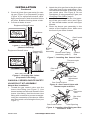
The GA9050A-1 Series Manual On/Off Safety Valve/Pilot kit contains the following:
• PiezoIgnitor 097159-04
• ManualValve 901068-02
• PilotBurner(withnatural
gasorice) 901069-01
• PiezoIgnitorElectrode 901072-01
• SteelShroud-PilotKit 901139-01
• PilotKitIncidentals 901152-01
• ControlDialInstructions 901042-01
• Brass3/8FLRx3/8MPTElbow 14264
• 18"Propane/LPBrassOrice 901065-02
• 24"Propane/LPBrassOrice 901065-03
• 30"Propane/LPBrassOrice 901065-04
• Propane/LPBrassAirMixer 901066-02
• Propane/LPPilotBurnerOrice901070-01
• Screw1/4"#8“B”pt(4ea.) 901075-01
• PilotValveControlDial 901079-01
• PilotValveDialExtension3" 901080-01
• PropaneConversionDecal 901691-01

www.fmiproducts.com
901054-01N2
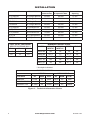
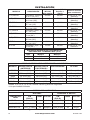
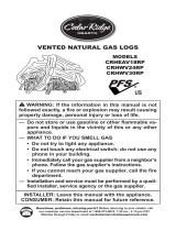
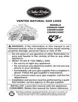
MODEL DESCRIPTION
Natural Gas
B
Minimum Vent
(C,F)VSR18 18"SingleBurner 50,000 40,000 8"dia.
(C,F)VSR24 24"SingleBurner 60,000 50,000 8"dia.
CPVSR18 18"SingleBurner 50,000 40,000 8"dia.
CPVSR24 24"SingleBurner 60,000 50,000 8"dia.
(C,F)VDR18 18"DualBurner 55,000 45,000 8"dia.
(C,F)VDR24 24"DualBurner 65,000 55,000 8"dia.
(C,F)VDR30 30"DualBurner 70,000 60,000 8"dia.
BFLT18 18"TripleBurner 65,000 55,000 8"dia.
BFLT24 24"TripleBurner 70,000 60,000 8"dia.
*Add6"ifsafetyvalve/pilotisused
**Atdepthindicated
Gas Min. Max.
NG 5.5" 10.5"
LP 11" 13"
PROPANE/LP
LOG SIZE
18SR/DR 0.120 31 Blue 0.073 49 Red
24SR/DR/BFLT18 0.129 30 Green 0.086 44
Orange
30DR/BFLT24 0.1405 28 Yellow 0.089 43 Black
INSTALLATION
MODEL
WIDTH*
BACK
WIDTH**
DEPTH HEIGHT
18DR/SR 28" 16" 14" 18"
24DR/SR 29
3
/
4
" 17" 15
1
/
2
" 18"
30DR 36" 27" 18" 18"
BFLT18 28" 16" 15
1
/
2
" 18"
BFLT24 30" 22" 15
1
/
2
" 18"
Figure 1 - Technical Information Charts

www.fmiproducts.com
901054-01N 3
CHECK GAS TYPE
YoumustinstallthisON/OFFSafetyValve/
PilotKitifyourgastypeispropane/LP.Forad-
ditionalconvenienceandsafety,thisON/OFF
SafetyValve/PilotKitcanbeusedwithnatural
gas.Ifyouareunsureoftheproperapplica-
tion,calldealerwhereyouboughtlogset.
Ifthereplacedoesnothaveagassupply
shutoffvalve,onemustbeinstalled.
-
the external regulator between the
Installation Items Needed
Beforeinstallinglogset,makesureyouhave
theitemslistedbelow.
• piping(checklocalcodes)
• sealant(resistanttopropane/LPgas)
• equipmentshutoffvalve*
• testgaugeconnection*
• adjustable(crescent)wrenchorpliers
• sedimenttrap
• teejoint
• pipewrench
• exiblegasline
• 10mmDeepSocket
*A equipment shutoff valve with 1/8" NPT
tapisanacceptablealternativetotestgauge
connection.Purchasetheoptionalequipment
shutoffvalvefromyourdealer.
INSTALLATION
Continued
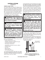
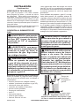
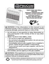
Forpropane/LPunits,theinstallermustsupply
anexternalregulator.Theexternalregulator
willreduceincominggaspressure.Youmust
reduceincominggaspressuretobetween11"
and14"ofwater.Ifyoudonotreduceincom-
inggaspressure, heater regulator damage
could occur. Install external regulator with
theventpointingdownasshowninFigure2.
Pointingtheventdownprotectsitfromfreez-
ingrainorsleet.
WARNING: Never connect
gas is commonly known as
-
1/2" diameter or greater to allow
Installationmustincludeanequipmentshut-
offvalve,union,andplugged1/8"NPTtap.
LocateNPTtapwithinreachfortestgauge
hookup.NPTtapmustbeupstreamfromlog
set(seeFigure3,page4).
IMPORTANT:Installequipmentshutoffvalve
in an accessible location.Theequipment
shutoff valve is for turning on or shutting off
thegastotheappliance.
Figure 2 - External Regulator on
Propane/LP Supply Tank with Vent
Pointing Down
ExternalRegulator
VentPointingDown
Propane/LP
SupplyTank

www.fmiproducts.com
901054-01N4
Checkyour building codesfor any special
requirementsforlocatingequipmentshutoff
valvetoappliance.
ApplypipejointsealantlightlytomaleNPT
threads.Thiswillpreventexcesssealantfrom
goingintopipe.Excesssealantinpipecould
resultinacloggedburnerorice.
sealant that is resistant to liquid
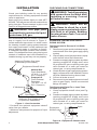
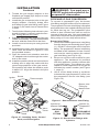
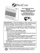
Werecommendthatyou installa sediment
trapin supply line as shown in Figure 3.
Locatesedimenttrapwhereitiswithinreach
forcleaning.Installinpipingsystembetween
fuelsupplyandheater.Locatesedimenttrap
wheretrappedmatterisnotlikelytofreeze.
Asedimenttraptrapsmoistureandcontami-
nants.Thiskeepsthemfromgoingintologset
controls.Ifsedimenttrapisnotinstalledoris
installedwrong,logsetmaynotrunproperly.
INSTALLATION
Continued
Natural Gas
FromGasMeter
(5"W.C.**to10.5"
W.C.Pressure)
FromExternal
Regulator
(11"W.C.**to14"
W.C.Pressure)
Figure 3 - Gas Connection
* Purchase the optional equipmentshutoff
valvefromyourdealer.
**Minimuminletpressureforpurposeofinput
adjustment.
3"Minimum
SedimentTrap(Optionalfor
Propane/LPInstallation)
EquipmentShutoffValve*
ApprovedFlexibleGasHose
(ifallowedbylocalcodes)
Tee Joint
PipeNipple
Cap
Figure 4 - Equipment Shutoff Valve
Open
Closed
Equipment
Shutoff Valve
CHECKING GAS CONNECTIONS
and connections for leaks after
WARNING: Never use an
-
PIPING SYSTEM
Test Pressures In Excess Of 1/2 PSIG
1. Disconnectlogsetanditsindividualequip-
mentshutoffvalvefromgassupplypiping
system.
2. Capoffopenendofgaspipewhereequip-
mentshutoffvalvewasconnected.
3. Pressurizesupplypipingsystembyeither
opening propane/LP supply tank valve
forpropane/LPgasoropeningmaingas
valve located onor neargas meterfor
naturalgas,orusingcompressedair.
4. Checkalljointsofgassupplypipingsystem.
Applynoncorrosiveleakdetectionuidto
alljoints.Bubblesformingshowaleak.
5. Correctallleaksatonce.
6. Reconnectlogsetandequipmentshutoff
valvetogassupply.Checkreconnected
ttingsforleaks.
Test Pressures Equal To or Less Than
1. Closeequipmentshutoffvalve(seeFig-
ure4).
2. Pressurizesupplypipingsystembyeither
opening propane/LPsupplytank valve
forpropane/LPgasoropeningmaingas
valve located onor neargas meterfor
naturalgas,orusingcompressedair.

www.fmiproducts.com
901054-01N 5
INSTALLATION
Continued
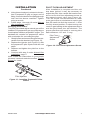
Figure 5 - Checking Gas Joints
(Natural Gas Only)
Gas Meter
EquipmentShutoffValve
Propane/LP
SupplyTank
EquipmentShutoffValve
Figure 6 - Checking Gas Joints
(Propane/LP Gas Only)
VALVE/PILOT KIT ASSEMBLY
Natural Gas Installation
1. Thread the gas control valve onto the
burner inlet tting(see Figure7). Use
threadsealantonthemalethreadsofthe
burnerinlettting.Holdthe burnerinlet
ttingwithawrenchtopreventovertight-
eningtheconnectiontotheburner.Make
surethecontrolrodisfacingthefront(see
Figure7).
BurnerInletFitting
(containingorice)
GasControl
Valve
Burner
Pan
Assembly
Figure 7 - Installing Gas Control Valve
Control
Rod
Figure 8 - Gas Control Valve with
Thermocouple and Pilot
Thermocouple
andLine
Pilotand
Line
GasControlValve
PilotFlow
Adjustment
Screw
Figure 9 - Installing Inlet Fitting and Gas
Connector Tube
GasControlValve
GasInlet
Fitting
Gas
Connector
Tube
InletOpening
3. Checkalljointsfromgasmeterfornatu-
ralgas(Figure5)orpropane/LPsupply
(Figure6)toequipmentshutoff valve.
Applynoncorrosiveleakdetectionuidto
alljoints.Bubblesformingshowaleak.
4. Correctallleaksatonce.
2. Attachthepilotgaslinetothepilotoutlet
ofthegascontrolvalveandtighten.Con-
nectthethermocoupletotherearofthe
gascontrolvalve.SeeFigure8.Donot
overtighten.Ifusingpropane/LPgas,see
Changing Pilot Orice,page6.
3. Installtheinletttingintotheinletopen-
ingofthegascontrolvalve(seeFigure
9).Usethreadsealantonthemalepipe
threads.
4. Place the burner pan assemblyin the
center of the replaceoor. Make sure
thefrontofpanfacesforward.

www.fmiproducts.com
901054-01N6
5. Thread the gas supply adaptor to the
replacegassupplypipe.Adjusttomost
convenientposition.
6. Installthegasconnectortubetothegas
supply adaptor. Carefullyshape tube
andattachtogasinlettting(seeFigure
9,page5).Becarefulnottocausekinks
intube.
7. Testforleaksfollowinginstructionsinyour
hearthkitowner’smanualunderthesec-
tion Testing Burner for Leaks.
8. Retightenandadjustthelocationofthegas
controlasnecessary.Thegascontrolshould
belevel,withthecontrolrodtothefront.
9. Installcovertoburnerpanusingscrews
provided.
10.Installthermocouple,pilot,andignitoronto
valvecoverasshowninFigure10.Use
theprovidedscrews.
11.Pushthecontrolrodextensionontothe
“D”shapedcontrolrodthroughthecenter
holeinthecover.
12.Installthepositiondecalandcontrolknob
making sure to align the marks with the
correctstoppositionsofthegascontrol.
Pilotpositionwillallowtheknobtopush
inabout1/2".Alignthedecalsinthepilot
position.
INSTALLATION
Continued
Piezo
Ignitor
Control
Rod
Extension
Screw
Valve
Cover
Control
Knob
Figure 10 - Installing Cover, Control
Knob, and Piezo Ignitor
Thermocouple
Ignitor
Pilot
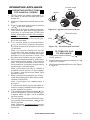
Figure 12 - Burner Inlet Fittings with
Injectors
GAS
PROPANE/LP
Injectorfor
NaturalGas
Injectorfor
Propane/LP
Gas
Figure 11 - Remove Burner Inlet Fitting
BurnerInlet
Fittingfor
NaturalGas
WARNING: You must use a
PROPANE/LP GAS CONVERSION
Toconvert to propane/LP gas, the burner
inletttingandpilotoricemustbereplaced.
Thepropane/LPburnerinletttingissupplied
alongwiththreecolorcodedoricespre-sized
foreach sizelogset.The propane/LPpilot
oriceis also includedand can beused to
convertallsizelogsets.Youmustinstallthe
correctsizeoriceintothepropane/LPburner
ttingusinga10mmdeepsocketdriver.
1. Removethenaturalgasburnerinlettting
fromtheburnerpanassembly(seeFigure
11).DONOTremovetheoricefromthis
tting.Thepropane/LPburnerinlettting
includedinthehardwarekithas6holes
andmustbeusedtoreplacethenatural
gasinlettting(seeFigure12).
2. Besuretousethecorrectoriceforyour
appliance. The hardware kit included
withthisappliancecontainsoriceswith
acone-likeshape.Theoricesarecolor
codedforeachrespectivesizelogsetas
indicatedbymodelnumber(see Figure
1,page2).
3. Usea10mmdeepsocketornutdriver
tothreadthenewpropane/LPoriceinto
the propane/LPburnerinlettting(see
Figure12).

www.fmiproducts.com
901054-01N 7
4. Usingthreadsealant(resistanttotheac-
tionofpropane/LPgas)onlargerendof
tting,screwtheburnerinletttingthrough
holeand intoburner manifold.Tighten
usingawrench.
5. Followsteps1through12underNatural
Gas Installation,page5.
Thepilotisprovidedwithanaturalgasorice
installed.Forpropane/LPgasyoumustremove
itandreplaceitwithanpropane/LPorice.The
hardwarekitcontainsanpropane/LPorice
witharedstripeforconvertingthepilot.
1. Gentlyloosenandremovethepilotlinecon-
nectionfromthebracket(seeFigure13).
2. Replacetheinjector(seeFigure13)with
thepropane/LPpilotinjectorwiththered
stripe.
3. Replaceandtightenthepilotlinetothe
bracket.
4. Continuewithstep3underNatural Gas
Installation, page5.
Note:Followtheinstructionsinyourhearth
kitowner’smanualunderthesection,Testing
Burner for Leaks.
Afterinstallation is complete and the unit
hasbeen ignited, itmaybe necessary to
adjustthepilot.Useasmallat-headscrew-
drivertoturntheowadjustmentscrewon
themanual controlvalve(see Figure14).
Turn the screw counterclockwise to allow
moregastooworclockwisetorestrictgas
ow.Becarefultolimittheturnsto2
1
/
2
from
thefullyclosedposition.Furtherturningcan
resultingasleakingattheadjustmentscrew
andthepilotamesizewilldiminish.The
properpilotowwillresultinastrongblue
amebetween1/2"and1"long.
INSTALLATION
Continued
Figure 13 - Installing Propane/LP Pilot
Orice
O
F
F
P
I
L
O
T
O
N
PilotInjector
PilotFlow
Adjustment
Screw
Figure 14 - Pilot Flow Adjustment Screw

www.fmiproducts.com
901054-01N8
Pilot
Thermocouple
Figure 16 - Thermocouple and Pilot
TO APPLIANCE
1. Turncontrolknobclockwise to the
PILOTposition.
2. Pressinandturncontrolclockwise
totheOFFposition.
3. Closeequipmentshutoffvalve(seeFigure
4,page4).
OPERATING APPLIANCE
1.
STOP!Read the safety information, in
theowner’smanual includedwithyour
hearthkit.
2. Makesureequipmentshutoffvalveisfully
open.
3. Pressinandturncontrolknobclockwise
totheOFFposition.
4. Waitve(5)minutestoclearoutanygas.
Then smellfor gas aroundlog set and
nearoor.Ifyousmellgas,STOP!See
SafetyinformationandAir For Combus-
tion and Ventilation, inyour hearth kit
owner’smanual.Ifyoudon’t smellgas,
gotothenextstep.
5.
Turn control knob counterclockwise
tothePILOTpositionandpress
in.Keepcontrolknobpressedinforve
(5)seconds.
Note: You may be running this log set
for the rst time after hooking up to gas
supply. If so, control knob may need to be
pressed in for 30 seconds or more. This
will allow air to bleed from gas system.
6. Withcontrolknobpressedin,pushdown
andreleaseignitorbutton.Thiswilllight
pilot.Thepilotisattachedtotherearof
thefrontburner.Ifneeded,keeppressing
ignitorbuttonuntilpilotlights.
Note: If pilot does not stay lit, contact a
qualied service person or gas supplier
for repairs. Until repairs are made, light
pilot with match.
7. Keepcontrolknobpressedinfor30sec-
ondsafterlightingpilot.After30seconds,
releasecontrolknob.
Note: If pilot goes out, repeat steps 3
through 7.
Ifcontrolknobdoesnotpopupwhenre-
leased,contactaqualiedserviceperson
orgassupplierforrepairs.
8. Turncontrolknobcounterclockwise
totheONposition.Burner shouldlight.
If burner does not light, call a qualied
serviceperson.
9. Toleavepilotlitandshutoffburnersonly,
turncontrolknobclockwise
to the
PILOTposition.
Note: Follow the Troubleshooting section
in the owner’s manual included with your
hearth kit.
Ignitor
Pilot
FROM"PILOT"POSITION
SLIGHTPUSHTO
TURNOFF
PULLPUSH
TOLIGHT
ON
ON
FROM"PILOT"POSITION
SLIGHTPUSHTO
TURNOFF
PULLPUSH
TOLIGHT
FROM"PILOT"POSITION
SLIGHTPUSHTO
TURNOFF
PULLPUSH
TOLIGHT
ON OFF
On
Off
OFF
OFF
Figure 15 - Ignitor and Control Knob
ControlKnob

www.fmiproducts.com
901054-01N 9
NOTES
_____________________________________________________
______________________________________________________
______________________________________________________
______________________________________________________
______________________________________________________
______________________________________________________
______________________________________________________
______________________________________________________
______________________________________________________
______________________________________________________
______________________________________________________
______________________________________________________
______________________________________________________
_____________________________________________________
______________________________________________________
______________________________________________________
______________________________________________________
______________________________________________________
______________________________________________________
______________________________________________________
______________________________________________________
______________________________________________________

901054-01
Rev.N
09/09
WARRANTY
KEEP THIS WARRANTY
FMI PRODUCTS, LLC LIMITED WARRANTIES
New Products
Standard Warranty:FMIPRODUCTS,LLCwarrantsthisnewproductandanypartsthereoftobefreefromdefects
inmaterialandworkmanshipforaperiodoftwo(2)yearsfromthedateofrstpurchasefromanauthorizeddealer
providedtheproducthasbeeninstalled,maintainedandoperatedinaccordancewithFMIPRODUCTS,LLC’s
warningsandinstructions.
Forproductspurchasedforcommercial,industrialorrentalusage,thiswarrantyislimitedto90daysfromthedate
ofrstpurchase.
Limited Warranty:FMIPRODUCTS,LLCwarrantsfactoryreconditionedproductsandanypartsthereoftobe
freefromdefectsinmaterialandworkmanshipfor30daysfromthedateofrstpurchasefromanauthorizeddealer
providedtheproducthasbeeninstalled,maintainedandoperatedinaccordancewithFMIPRODUCTS,LLC’s
warningsandinstructions.
Terms Common to All Warranties
Thefollowingtermsapplytoalloftheabovewarranties:
Alwaysspecifymodelnumberandserialnumberwhencontactingthemanufacturer.Tomakeaclaimunderthis
warrantythebillofsaleorotherproofofpurchasemustbepresented.
Thiswarrantyisextendedonlytotheoriginalretailpurchaserwhenpurchasedfromanauthorizeddealer,andonly
wheninstalledbyaqualiedinstallerinaccordancewithalllocalcodesandinstructionsfurnishedwiththisproduct.
Thiswarrantycoversthecostofpart(s)requiredtorestorethisproducttoproperoperatingconditionandanallow-
anceforlaborwhenprovidedbyaFMIPRODUCTS,LLCAuthorizedServiceCenteroraproviderapprovedby
FMIPRODUCTS,LLC.Warrantypartsmustbeobtainedthroughauthorizeddealersofthisproductand/orFMI
PRODUCTS,LLCwhowillprovideoriginalfactoryreplacementparts.Failuretouseoriginalfactoryreplacement
partsvoidsthiswarranty.
Travel,handling,transportation,diagnostic,material,laborandincidentalcostsassociatedwithwarrantyrepairs,
unlessexpresslycoveredbythiswarranty,arenotreimbursableunderthiswarrantyandaretheresponsibilityof
theowner.
Excludedfromthiswarrantyareproductsorpartsthatfailorbecomedamagedduetomisuse,accidents,improper
installation,lackofpropermaintenance,tampering,oralteration(s).
ThisisFMIPRODUCTS,LLC’sexclusivewarranty,andtothefullextentallowedbylaw;thisexpresswarranty
excludesanyandallotherwarranties,expressorimplied,writtenorverbalandlimitsthedurationofanyandall
impliedwarranties,includingwarrantiesofmerchantabilityandtnessforaparticularpurposetotwo(2)yearson
newproductsand30daysonfactoryreconditionedproductsfromthedateofrstpurchase.FMIPRODUCTS,LLC
makesnootherwarrantiesregardingthisproduct.
FMIPRODUCTS,LLC’sliabilityislimitedtothepurchasepriceoftheproduct,andFMIPRODUCTS,LLCshallnot
beliableforanyotherdamageswhatsoeverunderanycircumstancesincludingindirect,incidental,orconsequential
damages.
Somestatesdonotallowlimitationsonhowlonganimpliedwarrantylastsortheexclusionorlimitationofincidental
orconsequentialdamages,sotheabovelimitationorexclusionmaynotapplytoyou.
Thiswarrantygivesyouspeciclegalrights,andyoumayalsohaveotherrightswhichvaryfromstatetostate.
Forinformationaboutthiswarrantycontact:
Model(
locatedonproductoridenticationtag
) _____________________________
SerialNo.(
locatedonproductoridenticationtag
) __________________________
DatePurchased __________________________
Keepreceiptforwarrantyverication.
2701S.HarborBlvd.
SantaAna,CA92704
1-866-328-4538
www.fmiproducts.com

Guarde este manual para referencias futuras.
Para obtener más información, visite www.fmiproducts.com
SERIE GA9050A-1 PAQUETE DE PILOTO Y VÁLVULA DE
CIERRE DE SEGURIDAD MANUAL
Para todos los leños con quemador sencillo, doble o triple de
gas natural y propano o gas LP
-
— La instalación y el servicio deben ser realizados
-
información adicionales consulte a un instalador ca-
Elpaquetede piloto yválvuladecierre de seguridad manualde laserie GA9050A-1
contiene lo siguiente:
• encendidopiezoeléctrico 097159-04
• válvulamanual 901068-02
• quemadordepiloto(con
orificioparagasnatural) 901069-01
• electrodoparaencendido
piezoeléctrico 901072-01
• armazóndeacero,paquetede
piloto 901139-01
• elementosnoincluidosenel
paquetedepiloto 901152-01
• instructivoparaelcuadrante
demando 901042-01
•
cododelatónde3/8FLRx3/8MPT
14264
• orificiode45.7cm(18")delatón
parapropanoogasLP 901065-02
• orificiode61cm(24")delatón
parapropanoogasLP 901065-03
• orificiode76.2cm(30")de
latónparapropanoogasLP 901065-04
• mezcladordeairedelatón
parapropanoogasLP 901066-02
• orificioparaquemadorde
pilotoparapropanoogasLP 901070-01
• tornillode1/4"#8“B”pt(4) 901075-01
• cuadrantedemandopara
válvuladepiloto 901079-01
• extensiónde7.62cm(3")para
cuadrantedeválvuladepiloto 901080-01
•
etiquetadeconversiónalpropano
901691-01

www.fmiproducts.com
901054-01N12
MODELO DESCRIPCIÓN
Entrada
Gas natural
Entrada
gas LP
Abertura mínima
(C,F)VSR18 Quemador sencillo
de45.7cm(18")
50,000 40,000 20.32cm(8")de
diámetro
(C,F)VSR24 Quemador sencillo
de61cm(24")
60,000 50,000 20.32cm(8")de
diámetro
CPVSR18 Quemador doble de
45.7cm(18")
50,000 40,000 20.32cm(8")de
diámetro
CPVSR24 Quemador sencillo
de61cm(24")
60,000 50,000 20.32cm(8")de
diámetro
(C,F)VDR18
Quemador doble de
45.7cm(18")
55,000 45,000 20.32cm(8")de
diámetro
(C,F)VDR24
Quemador doble de
61cm(24")
65,000 55,000 20.32cm(8")de
diámetro
(C,F)VDR30 Quemador doble de
76.2cm(30")
70,000 60,000 20.32cm(8")de
diámetro
BFLT18 Quemador triple de
45.7cm(18")
65,000 55,000 20.32cm(8")de
diámetro
BFLT24 Quemador triple de
61cm(24")
70,000 60,000 20.32cm(8")de
diámetro
*Añada15.2cm(6")sisevaautilizarválvulaypilotodeseguridad
**Alaprofundidadindicada
Gas Mínimo Máximo
GN 5.5" 10.5"
LP 11" 13"
PROPANO O GAS LP
TAMAÑO DEL
LEÑO
CM
COLOR CM
COLOR
18SR/DR 0.304(0.120) 31 Azul 0.185(0.073) 49 Rojo
24SR/DR/BFLT18 0.327(0.129) 30 Verde 0.218(0.086) 44
Naranja
30DR/BFLT24 0.357(0.1405) 28 Amarillo 0.226(0.089) 43 Negro
INSTALACIÓN
MEDIDAS MÍNIMAS DEL INTERIOR DE LA CHIMENEA
MODELO ANCHO PARTE
ANTERIOR*
ANCHO PARTE
POSTERIOR**
18DR/SR 71.1cm(28") 40.6cm(16") 35.6cm(14") 45.7cm(18")
24DR/SR 75.6cm(29.8") 43.2cm(17") 39.4cm(15.5") 45.7cm(18")
30DR 91.4cm(36") 68.6cm(27") 45.7cm(18") 45.7cm(18")
BFLT18 71.1cm(28") 40.6cm(16") 39.4cm(15.5") 45.7cm(18")
BFLT24 76.2cm(30") 55.9cm(22") 39.4cm(15.5") 45.7cm(18")
Figura 1 - Tablas de información técnica

www.fmiproducts.com
901054-01N 13
*Unaválvuladecierredeequipoconrosca
tipoNPTde1/8"esunaalternativaaceptable
alaconexióndemedidordeprueba.Adquiera
laválvulaopcionaldecierrede equipo del
distribuidor.
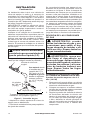
ParaunidadesdepropanoogasLP,elinsta-
ladordebeproveerunreguladorexterno.El
reguladorexternoreducirálapresióndelgas
entrante.Usteddebereducirlapresióndelgas
entrantedemaneraqueseadeentre11"y14"
deagua.Sinoreducelapresióndelgasentran-
te,sepuedenproducirdañosalreguladordel
calentador.Instaleelreguladorexternoconla
ventilaapuntandohaciaabajo,comosemuestra
enlafigura2.Siapuntalaventilahaciaabajose
protegedelalluviaheladaoaguanieve.
ADVERTENCIA: nunca co-
-
mente tubería nueva de hierro
Si la tubería es demasiado an-
Si el gas es propano o LP debe instalar
estepaquete depiloto y válvula de cierre
de seguridad . Paramayor convenienciay
seguridad,estepaquetedepilotoyválvulade
cierredeseguridadsepuedeutilizarcongas
natural.Sinoestásegurosobrelaaplicación
correcta,llamealproveedorquelevendióel
juegodeleños.
Silachimeneanotieneválvulaparacerrarla
alimentacióndegas,debeinstalaruna.
GAS
requiere una conexión de entra-
-
-
o gas LP directamente al sumi-
Instale el regulador externo entre
el calentador y el suministro de
Antesdeinstalareljuegodeleños,asegú-
resedetenerlosartículosqueseindicana
continuación.
• tubería(consulteloscódigoslocales),
• sellador(resistentealpropanoogasLP),
• válvuladecierredelequipo*,
• conexióndemedidordeprueba*,
• pinzasollaveajustable,
• trampadesedimentos,
• uniónT,
• llaveparatubería,
• líneadegasflexible,
• llavedecubode10mm.
INSTALACIÓN
Continuación
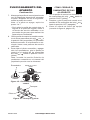
Figura 2 - Regulador externo en el
tanque de suministro de propano o gas
LP con la ventila orientada hacia abajo
Reguladorexterno
Ventilaapuntandohaciaabajo
Tanquede
suministro
depropanoo
gasLP

www.fmiproducts.com
901054-01N14
La instalación debe incluiruna válvula de
cierrede equipo, launión y elconector de
suministroconroscatipoNPTde1/8".Sitúe
laconexiónconroscatipoNPTasualcance
paralaconexióndelmedidordeprueba.La
conexióntipoNPTdebeestarantesdeljuego
deleños(consultelafigura3).
IMPORTANTE: instale laválvula de cierre
delequipoenunsitioaccesible.Laválvula
decierredelequipoesparaabrirocerrarel
suministrodegasalaparato.
Verifiquesiloscódigosdesuinmueblees-
tablecen requerimientos especiales para la
ubicacióndeválvulasdecierredeequipos.
Apliqueunapequeña cantidadde sellador
detuberíaen lasroscasNPTmacho. Esto
evitaráqueelexcesodeselladorentreala
tubería.Elexcesodeselladorenlatubería
puedeocasionarquelosorificiosdelquema-
dorsetapen.
ADVERTENCIA: use sellador
INSTALACIÓN
Continuación
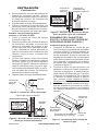
Gas naturaldesde
elmedidordegas
(presiónde5**a
10.5pulg.deC.A.)
desdeelregulador
externo(presión
de11**a14pulg.
deC.A.)
Figura 3 - Conexión de gas
*Adquiera la válvula opcional de cierre de
equipoconsudistribuidor.
**Presióndeentradamínimaparapropósitos
deajustedeentrada.
Unmínimo
de7.62cm
(3pulg.)
Trampadesedimentos(opcionalparala
instalaciónconpropanoogasLP)
Válvuladecierrede
equipo*
Mangueraflexibleaprobadaparagas(en
casoqueloscódigoslocaleslapermitan)
UniónT
NipledetuboTapa
Se recomienda instalar una trampa de se-
dimentosenlalíneadesuministrocomose
muestra enla figura3. Sitúe la trampade
sedimentosdemaneraquesepuedatener
accesoaellaparalimpieza.Instálelaen el
sistemadelatuberíaentreelsuministrode
combustibleyelcalentador.Sitúelatrampa
desedimentosdondeseapocoprobableque
losmaterialesatrapadosenellasecongelen.
La trampa de sedimentos atrapahumedad
y contaminantes. Lo cual evitaque estos
lleguenaloscontrolesdel juego de leños.
Silatrampadesedimentosnoseinstalao
seinstalaincorrectamente,esposiblequeel
juegodeleñosnofuncionecorrectamente.
DE GAS
todas las tuberías de gas y sus
ADVERTENCIA: nunca use
una llama al descubierto en
-
1. Desconecteeljuegodeleñosysuválvula
decierrecorrespondientedelsistemade
tuberíadealimentacióndegas.
2. Coloqueunatapaenelextremoabierto
deltubodegasdondeestabaconectada
laválvuladecierredelequipo.
3. Regulelapresióndelsistemadetubería
de suministro abriendo la válvula del
tanquedesuministrodepropanoogas
LP,encasoqueutiliceestetipodegas,
o bien, abriendo la válvulaprincipal de
gasqueselocalizaenelmedidordegas
natural ocercade éste,o usando aire
comprimido.

www.fmiproducts.com
901054-01N 15
4. Revisetodaslasunionesdelsistemade
tubería de suministro de gas. Aplique
líquidoparadetectarfugasnocorrosivo
en todaslasuniones.La formación de
burbujasindicaráunafuga.
5. Reparetodaslasfugasinmediatamente.
6. Vuelvaaconectareljuegodeleñosyla
válvuladecierredelequipoalsuministro
degas.Reviselosconectoresqueseco-
locaronnuevamenteenbuscadefugas.
1. Cierre la válvula de cierre del equipo
(consultelafigura4).
2. Regulelapresióndelsistemadetubería
de suministro abriendo la válvula del
tanquedesuministrodepropanoogas
LP,encasoqueutiliceestetipodegas,
o bien, abriendo la válvulaprincipal de
gasqueselocalizaenelmedidordegas
natural ocercade éste,o usando aire
comprimido.
3. Sitienegas natural, revise lasuniones
desdeelmedidordegashastalaválvula
decierre(figura5)ysitienesuministro
depropanoogasLP,desdeelsuministro
hastalaválvuladecierre(figura6).Apli-
quelíquidoparadetectarfugasnocorro-
sivoentodaslasuniones.Laformación
deburbujasindicaráunafuga.
4. Reparetodaslasfugasinmediatamente.
INSTALACIÓN
Continuación
Abierta
Cerrada
Válvulade
cierrede
equipo
Figura 5 - Revisión de las uniones de gas
(Para gas natural solamente)
Medidor
degas
Válvuladecierredeequipo
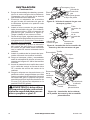
1. Enrosque laválvulade control de gas
conlaconexióndeentradadelquemador
(consultelafigura7).Apliqueselladoren
laroscamachodelaconexióndeentra-
dadelquemador.Sujetelaconexiónde
entradadelquemadorconunallavepara
evitarquelaconexiónalquemadorquede
muyapretada.Compruebequelavarilla
decontrolestéorientadahaciaelfrente
(consultelafigura7).
2. Conectela línea de gas del pilotoa la
salidadelaválvuladecontrolyapriétela.
Conecteeltermoparalaparteposterior
delaválvuladecontroldegas.Consulte
lafigura8enlapágina14.Noloapriete
enexceso. Si utilizapropanoo gas LP
gas, consulte Cómo cambiar el orificio
del piloto,enlapágina17.
3. Instalelaconexióndeentradaenlaaber-
turadeentradadelaválvuladecontrol
degas(consultelafigura9enlapágina
14).Apliqueselladorenlaroscamacho
deltubo.
Conexióndeentradadel
quemador(conorificio)
Válvulade
controlde
gas
Ensamblaje
decharolay
quemador
Figura 7 - Instalación de la válvula de
control de gas
Varillade
control
Tanquede
suministrode
propanoogasLP
Válvulade
cierrede
equipo
Figura 6 - Revisión de las uniones de gas
(Para propano o gas LP solamente)
Figura 4 - Válvula de cierre del equipo

www.fmiproducts.com
901054-01N16
4. Pongaelensamblajedecharolayquema-
dorenelcentrodelpisodelachimenea.
Compruebequeelfrentedelacharola
estéorientadohaciaadelante.
5. Enrosque el adaptador de suministro
degasaltubodesuministrodegasde
lachimenea.Ajústeloalaposiciónmás
conveniente.
6. Instaleeltuboconectordegasaladap-
tadordesuministrodegas.Concuidado,
déleformaaltuboyfíjeloalconectorde
entrada de gas (consulte la figura 9).
Tengacuidadodenoretorcereltubo.
7. Revisesihayfugas,sigalasinstrucciones
delmanualdelpropietariodelachimenea
queaparecenenlasecciónCómo detec-
tar fugas en el quemador.
8. Vuelvaaapretar y ajuste la ubicación
del control de gas según serequiera.
Elcontroldegasdebeestarhorizontal
conlavarilladecontrolorientadahacia
adelante.
9. Instalelacubiertadelacharoladelque-
madorutilizandolostornillosincluidos.
10.Pongaeltermopar,pilotoyencendedor
sobrelacubiertadelaválvula,talcomose
muestraenlafigura10.Utilicelostornillos
incluidos.
11.Insertelaextensióndelavarilladecontrol
enlavarilladecontrolenformadeletra
"D"atravésdelorificiodelcentrodela
cubierta.
12.Pongalaetiquetaconlasposicionesyla
perilladecontrol,asegurándosequecada
marcacorrespondaalaposicióncorrecta
delcontroldegas.Laposicióndelpiloto
permitirápresionarlaperillaalrededorde
13mm(1/2")Alinee lasetiquetasen la
posiciónPILOTO(piloto).
ADVERTENCIA: debe utilizar
-
INSTALACIÓN
Continuación
Encendido
piezoeléctrico
Extensión
dela
varillade
control
Tornillo
Cubiertade
laválvula
Perillade
control
Figura 10 - Instalación de la cubierta,
de la perilla de control y del encendido
piezoeléctrico
Termopar
Encendedor
Piloto
Figura 8 - Válvula de control de gas con
termopar y piloto
Termoparylínea
Piloto y
línea
Válvulade
controlde
gas
Tornilloparaajustar
elflujodelpiloto
Figura 9 - Instalación de la conexión de
entrada y del tubo conector de gas
Válvulade
controldegas
Conexión
dela
entradade
gas
Tubo
conectorde
gas
Aberturade
laentrada

www.fmiproducts.com
901054-01N 17
CONVERSIÓN A PROPANO O GAS LP
Para convertir a propano o gas LP, debe
reemplazarlaconexióndeentradadelque-
madoryelorificiodelpiloto.Laconexiónde
entrada del quemador para propano o gas
LPseproporcionajuntocontresorificiosde
diferentetamaño,cadaunoidentificadocon
uncolordistinto,paracadajuegodeleños.
Tambiénseincluyeelorificiodepilotopara
propanoogasLP,elcualsepuedeutilizar
paraconvertirtodoslostamañosdejuegos
deleños.Debeinstalarelorificiodeltamaño
correspondientealaconexióndelquemador
parapropanoogasLPconunallavedecubo
de10mm.
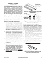
Conexión de entrada del quemador
1. Quitelaconexióndeentradadelquemador
delensamblajede charola y quemador
(consultelafigura11).NOquiteelorificio
deestaconexión.Laconexióndeentrada
delquemadorparapropanoogasLPque
se incluye en elpaquete de ferretería
tieneseisorificiosysedebeutilizarpara
reemplazarlaconexióndeentradapara
gasnatural(consultelafigura12).
2. Asegúresedeutilizarelorificiodetamaño
correctoparaelaparato.Elpaquetede
ferreteríaqueseincluyeconesteapa-
rato contiene orificiosdeforma cónica.
Losorificiossedistinguenporcolor,rojo
paracadatamañodejuegodeleños,tal
comoseindicaenelnúmerodemodelo
(consultelafigura1enlapágina12).
3. Utiliceunallavedecubode10mmouna
llave de tuercas para colocarelnuevo
orificioparapropanoogasLPenlaco-
nexióndeentradadelquemador(consulte
lafigura12).
4. Apliqueselladorpararoscas,resistente
alaaccióndelpropanoogasLP,enel
extremoanchodelaconexiónyatornille
laconexióndeentradadelquemadora
travésdelorificiohastael tubomúltiple
delquemador.Aprieteconunallave.
5. Realicelospasos1a12deInstalación
para gas natural,enlapágina15.
INSTALACIÓN
Continuación
Figura 12 - Conexiones de entrada del
quemador con inyectores
PARA GAS
PARA
PROPANO O
GAS LP
Inyector
paragas
natural
Inyector
para
propanoo
gasLP
Figura 11. Quite la conexión de entrada
del quemador
Conexiónde
entradadel
quemadorpara
gas natural
Elpilotoseproporcionaconorificioparagas
natural instalado. Para propano o gasLP,
deberetirarloyreemplazarloporunorificio
parapropanoogasLP.Elpaquetedeferrete-
ríacontieneunorificioparapropanoogasLP
conunafranjarojaparaconvertirelpiloto.
1. Concuidado,aflojeyquitelaconexión
delalíneadelpilotodelsoporte(con-
sultelafigura15).
2. Vuelvaacolocarelinyector(consultela
figura13)conelinyectordepilotopara
propanoogasLPconfranjaroja.
3. Reempláceloyaprietelalíneadelpiloto
enelsoporte.
4. Continúeconelpaso3delaInstalación
para gas natural, enlapágina13.
Nota:sigalasinstruccionesdelmanualdelpro-
pietariodelachimeneaqueaparecenenlasec-
ciónCómo detectar fugas en el quemador.
O
F
F
P
I
L
O
T
O
N
Inyectordelpiloto
Figura 13 - Instalación del orificio del
piloto para propano o gas LP

www.fmiproducts.com
901054-01N18
FUNCIONAMIENTO DEL
APARATO
1. ¡ALTO!Lealainformaciónsobreseguri-
dadcontenidaenelmanualdelpropietario
proporcionadojuntoconlachimenea.
2. Asegúresedequelaválvuladecierredel
equipoestécompletamenteabierta.
3. Presioneygirelaperilladecontrolenel
sentidodelasmanecillasdelreloj
hastalaposiciónOFF(apagado).
4. Esperecinco(5)minutosaquesedisipe
elgas.Luego,acérqueseparaverificarsi
sepercibeoloragasalrededordeljuego
deleñoseinclusocercadelsuelo.Siper-
cibeoloragas,¡DETÉNGASE!Consulte
lainformacióndeSeguridad y Aire para
combustión y ventilación,provistaenel
manualdel propietario de la chimenea.
Sinopercibeoloragas,continúeconel
siguientepaso.
5. Girelaperilladecontrolensentidocon-
trarioaldelasmanecillasdelreloj
alaposiciónPILOT(piloto)ypresiónela.
Manténgalapresionadadurantecinco(5)
segundos.
Nota: posiblemente ésta sea la primera
vez que hace funcionar este juego de
leños después de conectarlo al suministro
de gas. Si es así, es posible que deba
presionar la perilla de control durante 30
segundos o más. Esto permitirá que el
aire salga del sistema de gas.
6. Continúepresionandolaperilladecon-
troly,almismotiempo,oprimaysuelte
elbotóndeencendido.Estoencenderá
el piloto. El piloto está instalado en la
parteposteriordelquemadorfrontal.Si
es necesario, continúe presionando el
botóndelencendidohastaqueelpiloto
seencienda.
Nota: si el piloto no permanece encen-
dido, comuníquese con una persona de
servicio calificado o con su proveedor de
gas para que realice las reparaciones ne-
cesarias. Encienda el piloto con un fósforo
hasta que se realicen las reparaciones.
INSTALACIÓN
Continuación
Unavezquehayaterminadolainstalacióny
encendidolaunidad,posiblementeseanece-
sarioajustarelpiloto.Conundesarmadorpla-
nopequeño,gireeltornillodeajusteprovisto
enlaválvuladecontrolmanual(consultela
figura14).Gireeltornilloensentidocontrario
aldelasmanecillasdelrelojparaaumentar
elflujoy,paradisminuirlo,gireeltornilloen
elsentidodelasmanecillasdelreloj.Tenga
cuidadodelimitarlasvueltasa2
1
/
2
desdela
posiciónenlaqueelflujoestácompletamente
cerrado.Sigiraeltornillomásdeloindicado,
elgaspodríafugarsedeltornillodeajustey
la flama delpiloto seharíamáspequeña.
Elflujocorrectoalpilotoescuandolaflama
adquiereuncolorazulfuerteymidede1.3a
2.5cm(1/2"a1")delargo.
Tornillopara
ajustarelflujo
delpiloto
Figura 14 - Tornillo para ajustar el flujo
del piloto

www.fmiproducts.com
901054-01N 19
Encendedor
Figura 15 - Encendedor y perilla de
control
Piloto
Termopar
Figura 16 - Termopar y piloto
CÓMO CERRAR EL
AL APARATO
1. Girelaperilladecontrolenelsentidode
lasmanecillas del reloj
hasta la
posiciónPILOT(piloto).
2. Presioneygirelaperilladecontrolenel
sentidodelasmanecillasdelreloj
hastalaposiciónOFF(apagado).
3. Cierre la válvula de cierre del equipo
(consultelafigura4,página15).
Perilladecontrol
Piloto
DESDE LA POSICIÓN "PILOT"
-
OPRIMA PARA ENCENDER
ON
ON
DESDE LA POSICIÓN "PILOT"
-
Y OPRIMA PARA ENCENDER
DESDE LA POSICIÓN
LIGERAMENTE PARA
PARA ENCENDER
ON
APAGADO
Off
On
7. Mantengalaperilladecontrolpresionada
por30segundosdespuésdeencender
elpiloto.Despuésdelos 30segundos,
sueltelaperilladecontrol.
Nota: si el piloto se apaga, repita los
pasos 3 a 7.
•Sialsoltarlaperilladecontroléstano
regresaasuposiciónoriginal,llamea
untécnicodeserviciocalicadooasu
proveedordegasparaquerealicenlas
reparacionesnecesarias.
8. Girelaperilladecontrolensentidocontra-
rioaldelasmanecillasdelreloj
a
laposiciónON(encendido).Elquemador
deberáencender.Sielquemadornoen-
ciende,llameaunapersonadeservicio
calificada.
9. Paradejarelpilotoencendidoyapagar
sólo losquemadores,girelaperilla de
control en el sentido de las manecillas
del reloj
hasta la posición PILOT
(piloto).
Nota: consulte la sección Solución de
problemas contenida en el manual del
propietario provisto con la chimenea.
FUNCIONAMIENTO DEL
APARATO
Continuación

901054-01
Rev.N
09/09
GARANTÍA
GUARDE ESTA GARANTÍA
GARANTÍAS LIMITADAS DE FMI PRODUCTS, LLC
Productos nuevos
Garantía estándar:FMIPRODUCTS,LLCgarantizaqueesteproductonuevoycualquieradesuspartesestaránlibres
dedefectosenmaterialesymanodeobraduranteunperiododeun(2)añoapartirdelafechadelacompraoriginal
deundistribuidorautorizado,siempreycuandoelproductohayasidoinstalado,mantenidoyoperadodeacuerdocon
lasadvertenciaseinstruccionesdeFMIPRODUCTS,LLC.
Paraproductosadquiridosdeusocomercial,industrialoparaalquiler,estagarantíaestálimitadaa90díasapartirde
lafechadelacompraoriginal.
Productos reacondicionados de fábrica
Garantía limitada:FMIPRODUCTS,LLCgarantizaesteproductoreacondicionadodefábricaycualquieradesuspartes
contracualquierdefectoenmaterialesymanodeobradurantelosprimeros30díasapartirdelafechadelacompra
conundistribuidorautorizado,siempreycuandoelproductosehayainstalado,mantenidoyoperadodeacuerdocon
lasadvertenciaseinstruccionesdeFMIPRODUCTS,LLC.
Lossiguientestérminosseaplicanatodaslasgarantíasmencionadasanteriormente:
Especifiquesiemprelosnúmerosdemodeloydeseriealcomunicarseconelfabricante.Parahacerunareclamaciónal
amparodeestagarantíasedeberápresentarlafacturauotrocomprobantedecompra.
Estagarantíaseextiendesóloalcompradorminoristaoriginalcuandoelproductoseadquiriódeundistribuidorautorizadoy
solamentesilainstalaciónlarealizauninstaladorcalificadoquesigalosrequisitosdeloscódigoslocalesylasinstrucciones
quesehanincluidoconesteproducto.
Estagarantíacubreelcostodelaspiezasnecesariaspararestauraresteproductoasuscondicionescorrectasdefun-
cionamientoyunacantidadcompensatoriaparalamanodeobracuandoseanproporcionadasporuncentrodeservicio
autorizadodeFMIPRODUCTS,LLCoundistribuidoraprobado.Laspiezasbajogarantíasedebenobtenerdedistribuidores
autorizadosparaesteproductoodeDESAHeating,LLC,quienproporcionarápiezasdereemplazooriginalesdefábrica.
Estagarantíaquedaanuladasinoseutilizanpiezasdereemplazooriginalesdefábrica.
Losgastosdeviaje,manejo,transporte,diagnóstico,materiales,manodeobraycostosindirectosrelacionadosconlas
reparacionesbajogarantíanosonreembolsablesbajoestagarantíaysonresponsabilidaddelpropietario,amenosque
esténexplícitamentecubiertosporestagarantía.
Estagarantíanocubrelosproductosopiezasquefallenoresultendañadosaconsecuenciadelusoincorrecto,accidentes,
instalaciónincorrecta,faltademantenimientoadecuado,manipulaciónoalteraciones.
ÉstaeslagarantíaexclusivadeFMIPRODUCTS,LLCy,paratodoslosefectoslegales,estagarantíaexplícitaexcluye
atodaslasdemásgarantías,explícitasoimplícitas,escritasoverbales,ylimitaladuracióndecualquieradelasgarantías
implícitas,inclusolasgarantíasdecomerciabilidadeidoneidadparaunusoparticular,alplazodeun(2)añoparaproductos
nuevosy30díasparaproductosreacondicionadosdefábrica,apartirdelafechadelacompraoriginal.FMIPRODUCTS,
LLCnoofreceningunaotragarantíarelacionadaconesteproducto.
LaresponsabilidaddeFMIPRODUCTS,LLCselimitaalpreciodecompradelproductoyFMIPRODUCTS,LLCno
sehace responsable deningún otro daño bajo ningunacircunstancia, que incluyendaños indirectos, incidentalesy
consecuentes.
Algunosestadosnopermitenlaslimitacionesaladuracióndelasgarantíasimplícitasoalaexclusiónolimitacióndedaños
incidentalesoconsecuentes,demodoqueesposiblequelalimitaciónoexclusiónanteriornoseapliqueausted.
Estagarantíaleotorgaderechoslegalesespecíficosyposiblementetengaotrosderechosquevaríandeunestadoa
otro.
Paraobtenerinformaciónsobreestagarantía,comuníquesecon:
Modelo(localizadoenelproductooenlaetiquetadeidentificación) _________________________
Númerodeserie(localizadoenelproductooenlaetiquetadeidentificación) __________________
Fechadecompra ___________________________
Conservesureciboparalaverificacióndelagarantía.
2701S.HarborBlvd.
SantaAna,CA92704
1-866-328-4537
www.fmiproducts.com
-
 1
1
-
 2
2
-
 3
3
-
 4
4
-
 5
5
-
 6
6
-
 7
7
-
 8
8
-
 9
9
-
 10
10
-
 11
11
-
 12
12
-
 13
13
-
 14
14
-
 15
15
-
 16
16
-
 17
17
-
 18
18
-
 19
19
-
 20
20


FMI GA9050A-1 Instrucciones de operación
- Categoría
- Chimeneas
- Tipo
- Instrucciones de operación
en otros idiomas
- English: FMI GA9050A-1 Operating instructions
Artículos relacionados
Otros documentos
-
 Utilitech 9008073046 Guía de instalación
-
allen+roth SPK-200L Manual de usuario
-
Comfort Glow CVDR18 El manual del propietario
-
 ProCom Heating CRHEAV18RP Manual de usuario
-
 ProCom Heating CRHEAV18RP Manual de usuario
-
 ProCom Heating 140012 Manual de usuario
-
 ProCom Heating 140012 Guía de instalación
-
 Accu-Flo Meter Service Ltd. 01N Series Instrucciones de operación


