Husky F226VWD Manual de usuario
- Categoría
- Compresores de aire
- Tipo
- Manual de usuario

OPERATOR’S MANUAL
26 Gallon Portable Air Compressor
F226VWD / 585-819
Your air compressor has been engineered and manufactured to Husky’s high standard for dependability,
ease of operation, and operator safety. When properly cared for, it will give you years of rugged, trouble-
free performance.
Thank you for buying a Husky product.
SAVE THIS MANUAL FOR FUTURE REFERENCE
WARNING: To reduce the risk of injury, the user must read and understand the operator’s manual before
using this product.
02/09/2009

This tool has many features for making its use more pleasant and enjoyable. Safety, performance, and dependability have been
given top priority in the design of this product making it easy to maintain and operate.
CAUTION
This compressor is intended to be used at a duty cycle 50%.
DANGER
This compressor/pump is not equipped and should not be used to supply breathing quality air. Additional equipment
wouldbenecessarytoproperlylterandpurifytheairtomeetminimalspecicationsforGradeDbreathingasdescribed
inCompressed GasAssociation Commodity Specication G 7.1 - 1966, OSHA29CFR1910.134. Compressed Gas
Association, 4221 Walney Road, Fifth Floor, Chantilly, VA 20151-2923, (703) 788-2700, www.cganet.com.Any such
additional equipment has not been examined and no implication of proper use for breathing air is intended or implied. If this
compressor is altered in any way, existing warranties shall be voided. Husky and MAT Holdings, Inc. disclaim
any liabilities whatsoever for any loss, personal injury, or damage.
TABLE OF CONTENTS
g GeneralSafetyRules .............................................................1-2
g SpecicSafetyRules...............................................................3
g Symbols........................................................................4-5
g Electrical ........................................................................6
g GlossaryofTerms .................................................................7
g Features........................................................................8-9
g Assembly ........................................................................9
g Operation.....................................................................10-13
g Maintenance ....................................................................14
g Troubleshooting ..................................................................15
g ExplodedView...................................................................16
g Parts List .......................................................................17
g Warranty .......................................................................18
g Notes ..........................................................................19
INTRODUCTION

WARNING
Readandunderstandallinstructions.Failuretofollowall
instructionslistedbelowmayresultinelectricshock,re,
and/or serious personal injury.
SAVE THESE INSTRUCTIONS
WORK AREA
g Keep your work area clean and well lit. Cluttered
benchesanddarkareasinviteaccidents.Floormustnotbe
slippery from wax or dust.
gDo not operate power tools in explosive atmospheres,
such as in the presence of flammable liquids, gases,
or dust. Power tools create sparks which may ignite the
dust or fumes.
g Keep bystanders, children, and visitors away while
operating tools. Distractions can cause youto lose
control.
g Operate air compressor in an open area at least 18 in.
away from any wall or object that could restrict the
flow of fresh air to ventilation openings.
ELECTRICAL SAFETY
g Avoid body contact with grounded surfaces such as
pipes, radiators, ranges, and refrigerators. There is an
increased risk of electric shock if your body is grounded.
g Don’t expose power tools to rain or wet conditions.
Water entering a power tool will increase the risk of electric
shock.
g Do not abuse the cord. Never use the cord to carry the
tool or pull the plug from an outlet. Keep cord away
from heat, oil, sharp edges, or moving parts. Replace
damaged cords immediately. Damaged cords increase
the risk of electric shock.
g When operating a power tool outside, use an outdoor
extension cord marked “W-A” or “W”. These cords are
rated for outdoor use and reduce the risk of electric shock.
PERSONAL SAFETY
g Eye protection which conforms to ANSI specifications
and provides protection against flying particles both
from the FRONT and SIDE should ALWAYS be worn by
the operator and others in the work area when loading,
operating, or servicing this tool. Eye protection is
requiredtoguardagainstyingfastenersanddebris,which
could cause severe eye injury.
g The employer and/or user must ensure that proper eye
protection is worn.WerecommendaWideVisionSafety
Mask for use over eyeglasses or standard safety glasses
thatprovideprotectionagainstyingparticlesbothfromthe
front and side. Always use eye protection which is marked
tocomplywithANSIZ87.1.
g Additional safety protection will be required in some
environments.Forexample,theworkingareamayinclude
exposure to a noise level which can lead to hearing
damage. The employer and user must ensure that any
necessary hearing protection is provided and used by the
operator and others in the work area. Some environments
will require the use of head protection equipment. When
required, the employer and user must ensure that head
protectionmarkedtocomplywithANSIZ89.1isused.
g Stay alert, watch what you are doing, and use common
sense when operating a power tool. Do not use tool
while tired or under the influence of drugs, alcohol, or
medication. A moment of inattention while operating power
tools may result in serious personal injury.
g Dress properly. Do not wear loose clothing or jewelry.
Contain long hair. Keep your hair, clothing, and
gloves away from moving parts. Loose clothes, jewelry,
or long hair can be caught in moving parts.
g Do not overreach. Keep proper footing and balance at
all times. Proper footing and balance enables better
control of the tool in unexpected situations.
g Use safety equipment. Always wear eye protection.
Dustmask,nonskidsafetyshoes,hardhat,orhearing
protection must be used for appropriate conditions.
g Do not use on a ladder or unstable support. Stable
footing on a solid surface enables better control of the tool
in unexpected situations.
TOOL USE AND CARE
g Do not exceed the pressure rating of any component
in the system.
g Protect material lines and air lines from damage or
puncture. Keep hose and power cord away from sharp
objects,chemicalspills,oil,solvents,andwetoors.
g Check hoses for weak or worn condition before each
use, making certain all connections are secure.Donot
use if defect is found. Purchase a new hose or notify an
authorized service center for examination or repair.
g Release all pressures within the system slowly. Dust
and debris may be harmful.
g Store idle tools out of the reach of children and other
untrained persons. Tools are dangerous in the hands of
untrained users.
Page 1
GENERAL SAFETY RULES

g Maintain tools with care.Followmaintenanceinstructions.
Properly maintained tools are easier to control.
g Check for misalignment or binding of moving parts,
breakage of parts, and any other condition that may
affect the tool’s operation. If damaged, have the tool
serviced before using. Many accidents are caused by
poorly maintained tools.
g Never point any tool toward yourself or others.
g Keep the exterior of the air compressor dry, clean, and
free from oil and grease. Always use a clean cloth when
cleaning. Never use brake fluids, gasoline, petroleum-
based products, or any strong solvents to clean the unit.
Followingthisrulewillreducetheriskofdeteriorationofthe
enclosure plastic.
SERVICE
g Tool service must be performed only by qualified repair
personnel. Service or maintenance performed by
unqualiedpersonnelmayresultinariskofinjury.
g Disconnect power supply, open drain valve to
decompress tank and allow water to drain, and allow
air compressor to become cool to the touch before
servicing. Turn pressure regulator knob fully c l o c k w i s e
after shutting off compressor.
g When servicing a tool, use only identical replacement
parts. Follow instructions in the Maintenance section
of this manual. Use of unauthorized parts or failure to
follow Maintenance instructions may create a risk of injury.
Page 2
GENERAL SAFETY RULES

g Know your power tool.Readoperator’smanualcarefully.
Learnitsapplicationsandlimitations,aswellasthespecic
potentialhazardsrelated tothistool.Followingthisrulewill
reducetheriskofelectricshock,re,orseriousinjury.
g Drain tank of moisture after each day’s use. If unit will
not be used for a while, it is best to leave drain valve open
until such time as it is to be used. This will allow moisture
to completely drain out and help prevent corrosion on the
inside of tank.
g Risk of Fire or Explosion.Onlysprayammableliquids
suchaspaintsorlacquers.Neversprayammableliquids
inaconnedarea.Sprayareamustbewellventilated.Do
notsmokewhilesprayingorspraywheresparkorameis
present. Keep compressors as far from the spraying area
aspossible,atleast15feetfromthesprayingareaandall
explosive vapors.
g Risk of Bursting.Donotadjustregulatortoresultinoutput
pressure greater than marked maximum pressure of
attachment. Do not use a pressure greater than maximum
rated pressure of compressor.
g If connected to a circuit protected by fuses, use time-
delay fuses with this product.
g To reduce the risk of electric shock, do not expose to
rain. Store indoors.
g Inspect tank yearly for rust, pin holes, or other
imperfections that could cause it to become unsafe.
Never weld or drill holes in the air tank.
g Make sure the hose is free of obstructions or snags.
Entangled or snarled hoses can cause loss of balance or
footing and may become damaged.
g Use the air compressor only for its intended use. Do
not alter or modify the unit from the original design or
function.
gAlways be aware that misuse and improper handling of
this tool can cause injury to yourself and others.
gNever leave a tool unattended with the air hose attached.
gDo not operate this tool if it does not contain a legible
warning label.
gDo not continue to use a tool or hose that leaks air or
does not function properly.
g Always disconnect the air supply and power supply
before making adjustments, servicing a tool, or when a
tool is not in use.
gDo not attempt to pull or carry the air compressor by
the hose.
g Your tool may require more air consumption than this
air compressor is capable of providing.
g Never store tool with air connected. Storing the tool with
airconnectedcanresultinunexpectedringandpossible
serious personal injury.
gAlways follow all safety rules recommended by the
manufacturer of your air tool, in addition to all safety
rules for the air compressor. Following this rule will
reduce the risk of serious personal injury.
gNever direct a jet of compressed air toward people or
animals. Take care not to blow dust and dirt towards
yourself or others. Followingthisrulewillreducetherisk
of serious injury.
gProtect your lungs. Wear a face or dust mask if the
operationisdusty.Followingthisrulewillreducetherisk
of serious personal injury.
g Do not use this air compressor to spray chemicals. Your
lungs can be damaged by inhaling toxic fumes. A
respirator may be necessary in dusty environments or when
sprayingpaint.Donotcarrywhilepainting.
g Inspect tool cords and hoses periodically and, if
damaged, have repaired at your nearest Authorized
Service Center. Constantly stay aware of cord
location.Followingthisrulewillreducetheriskofelectric
shockorre.
g Never use an electrical adaptor with this grounded plug.
g Check damaged parts. Before further use of the air
compressor or air tool, a guard or other part that is
damaged should be carefully checked to determine
that it will operate properly and perform its intended
function. Check for alignment of moving parts,
binding of moving parts, breakage of parts,
mounting, and any other conditions that may affect
its operation. A guard or other part that is
damaged should be properly repaired or replaced by
an authorized service center. Following this rule will
reducetheriskofshock,re,orseriousinjury.
g Make sure your extension cord is in good condition.
When using an extension cord, be sure to use one
heavy enough to carry the current your product will
draw. A wire gauge size (A.W.G.) of at least 14 is
recommended for an extension cord 50 feet or less in
length. A cord exceeding 100 feet is not recommended.
If in doubt, use the next heavier gauge. The smaller
the gauge number, the heavier the cord. An undersized
cord will cause a drop in line voltage resulting in loss of
power and overheating.
g Save these instructions.Refertothemfrequentlyanduse
them to instruct others who may use this air compressor. If
you loan someone this tool, loan them these instructions
also.
Page 3
SPECIFIC SAFETY RULES

Page 4
Some of the following symbols may be used on this tool. Please study them and learn their meaning. Proper interpretation
of these symbols will allow you to operate the tool better and safer.
SYMBOLS
SYMBOL NAME DESIGNATION/EXPLANATION
V Volts Voltage
A Amperes Current
Hz Hertz Frequenct(cyclespersecond)
Alternating Current Type of current
Class II Construction Double-insulatedconstructon
Wet Conditions Alert Donotexposetorainoruseindamplocations.
ReadTheOperator’sManual To reduce the risk of injury, user must read and understand
operator’s manual before using this product.
Eye Protection Always wear safety goggles or safety glasses with side shields
and, as necessary, a full face shield when operating this product.
Safety Alert Precautions that involve your safety.
RiskofBursting Donotadjustregulatortoresultinoutputpressuregreaterthan
marked maximum pressure of attachment. Donotuseapres-
sure greater than maximum rated pressure of compressor.
RiskofFireorExplosion Donotsprayammableliquidinaconnedarea.Sprayarea
mustbewellventilated.Donotsmokewhilesprayingorspray
wheresparkorameispresent.Keepcompressorsasfarfrom
thesprayingareaaspossible,atleast15feetfromthespraying
area and all explosive vapors.
RiskofElectricalShock HazardousVoltage:Disconnectfrompowersourcebeforeser-
vicing.
Compressor must be grounded.
Hot Surface To reduce the risk of injury or damage, avoid contact with any
hot surface.
RisktoBreathing Air obtained directly from the air compressor should never be
used to supply air for human consumption.

Page 5
SYMBOLS
The following signal words and meanings are intended to explain the levels of risk associated with this product.
SYMBOL SIGNAL MEANING
DANGER
Indicates an imminently hazardous situation, which, if not avoided, will result in death or
serious injury.
WARNING
Indicates a potentially hazardous situation, which, if not avoided, could result in death or
serious injury.
CAUTION
Indicates a potentially hazardous situation, which, if not avoided, may result in minor or
moderate injury.
CAUTION
(WithoutSafetyAlertSymbol)Indicatesasituationthatmayresultinpropertydamage.
SERVICE
Servicing requires extreme care and knowledge and should be
performedonlybyaqualiedservicetechnician.Forservicewe
suggest you return the product to the nearest AUTHORIZED
SERVICE CENTER for repair. When servicing, use only identical
replacement parts.
WARNING
To avoid serious personal injury, do not attempt to use this
product until you read thoroughly and understand
completely the operator’s manual. If you do not
understand the warnings and instructions in the operator’s
manual, do not use this product. Call customer service for
assistance.
The operation of any power tool can result in foreign objects being thrown into your eyes, which can
result in severe eye damage. Before beginning power tool operation, always wear safety goggles or
safetyglasseswithsideshieldsand,whenneeded,afullfaceshield.WerecommendWideVisionSafety
Mask for use over eyeglasses or standard safety glasses with side shields. Always use eye protection
whichismarkedtocomplywithANSIZ87.1.
WARNING
SAVE THESE INSTRUCTIONS

EXTENSION CORDS
Useonly3-wireextensioncordsthathave3-pronggrounding
plugsand3-polereceptaclesthataccepttheproduct’splug.
When using a power tool at a considerable distance from the
power source, use an extension cord heavy enough to carry
the current that the product will draw. An undersized exten-
sion cord will cause a drop in line voltage, resulting in a loss
of power and causing the motor to overheat. Use the chart
provided below to determine the minimum wire size required
in an extensioncord. Only round jacketed cords listed by
Underwriter’sLaboratories(UL)shouldbeused.
When working with the product outdoors, use an extension
cord that is designed for outside use. This is indicated by the
letters “WA” on the cord’s jacket.
Beforeusinganextensioncord,inspectitforlooseorexposed
wires and cut or worn insulation.
WARNING
Keep the extension cord clear of the working area.
Position the cord so that it will not get caught on lumber,
tools, or other obstructions while you are working with a
powertool.Failuretodosocanresultinseriouspersonal
injury.
WARNING
Check extension cords before each use. If damaged
replace immediately. Never use the product with a
damaged cord since touching the damaged area could
cause electrical shock resulting in serious injury.
ELECTRICAL CONNECTION
This product is powered by a precision-built electric motor. It
should be connected to a power supply that is 120 volts, 60
Hz, AC only (normal household current). Do not operate
thisproductondirectcurrent(DC).Asubstantialvoltagedrop
will cause a loss of power and the motor will overheat. If the
product does not operate when plugged into an outlet, double
check the power supply.
SPEED AND WIRING
Theno-loadspeedofthisproductisapproximately3,450rpm.
This speed is not constant and decreases under a load or with
lowervoltage.Forvoltage,thewiringinashopisasimpor-
tant as the motor’s horsepower rating. A line intended only for
lights cannot properly carry a power tool motor. Wire that is
heavy enough for a short distance will be too light for a greater
distance. A line that can support one power tool may not be
able to support two or three products.
GROUNDING INSTRUCTIONS
This product must be grounded. In the event of a malfunction
or breakdown, grounding provides a path of least resistance
for electric current to reduce the risk of electric shock. This
product is equipped with an electric cord having an equipment-
grounding conductor and a grounding plug. The plug must be
plugged into a matching outlet that is properly installed and
grounded in accordance with all local codes and ordinances.
Donotmodifytheplugprovided.Ifitwillnotttheoutlet,have
theproperoutletinstalledbyaqualiedelectrician.Improper
connection of the equipment-grounding conductor can result
in a risk of electric shock. The conductor with insulation having
an outer surface that is green with or without yellow stripes is
the equipment-grounding conductor. If repair or replacement
of the electric cord or plug is necessary, do not connect the
equipment-grounding conductor to a live terminal.
Checkwithaqualiedelectricianorservicepersonnelifthe
grounding instructions are not completely understood, or if in
doubtastowhethertheproductisproperlygrounded.Repair
or replace a damaged or worn cord immediately.
This product is intended for use on a circuit that has an outlet
liketheoneshowninFigure1.Italsohasagroundingpinlike
theoneshown.Onlyconnecttheproducttoanoutlet
having the same conguration as the plug. Do not use an
adapter with this product.
Figure1
Page 6
ELECTRICAL
**Ampererating(onproductdataplate)
0 - 2.0 2.1-3.4 3.5-5.0 5.1-7.0 7.1-12.0 12.1-16.0
Cord Length Wire Size (A.W.G.)
25´ 16 16 16
16
14 14
50´ 16 16 16 14 14 12
100´ 26 16 14 12 10 —
**Usedon12gauge-20ampcircuit.
NOTE:AWG=AmericanWireGauge
GROUNDING PIN
120V GROUNDED OUTLET

Page 7
GLOSSARY OF TERMS
Air Filter
Porous element contained within a metal or plastic housing
attached to the compressor cylinder head which removes
impurities from the intake air of the compressor.
Air Tank
Cylindrical component which contains the compressed air.
Check Valve
Devicethatpreventscompressedairfromowingbackfrom
the air tank to the compressor pump.
Cut-In Pressure
The low pressure at which the motor will automatically restart.
Cut-Off Pressure
The high pressure at which the motor will automatically shut
off.
Electric Motor
Devicewhichprovidestherotationalforcenecessarytooperate
the compressor pump.
Manual Automatic/Off Switch
Control which turns the air compressor on or off. The pressure
switch will not automatically start and control the compressor
unlessthemanualAutomatic/OffSwitchisintheAUTOMATIC
( l ) position.
NPT (National Pipe Thread)
A seal thread tape must be used to provide a leak-free seal on
pipe threaded connections.
Pressure Regulator Knob
Regulatestheoutgoingpressurefromtheairoutlettothetool.
It is possible to increase or decrease the pressure at the outlet
by adjusting this control knob.
Pressure Switch
Automatically controls the on/off cycling of the compressor. It
stops the compressor when the cut-off pressure in the tank
is reached and starts the compressor when the air pressure
drops below the cut-in pressure.
PSI (Pounds Per Square Inch)
Measurement of the pressure exerted by the force of the
air. The actual psi is measured by a pressure gauge on the
compressor.
Pump
Produces the compressed air with a reciprocating piston
contained within the cylinder.
Regulator Pressure Gauge
Displaysthecurrentlinepressure.Linepressureisadjusted
by rotating the pressure regulator knob.
Pressure Relief Valve
Prevents air pressure in the air tank from rising over a
predetermined limit.
SCFM (Standard Cubic Feet Per Minute)
A unit of measure of air delivery.
Tank Pressure Gauge
Indicates the pressure in the air tank.
Thermal Overload Switch
Automatically shuts off the compressor if the temperature of
the electric motor exceeds a predetermined limit.

Page 8
FEATURES
PRODUCT SPECIFICATIONS
RunningHorsepower .....................................................1.5HP
Air Tank Capacity ........................................................... 26gal.
Air Pressure ........................................................ 150psimax.
AirDelivery ............................................... 4.0SCFM@90psi
Lubrication ...................................................................Oil-Free
Gauges ...............................................................2 in. diameter
Input................................... 120V,60Hz,ACOnly,15.0Amps
Net Weight .................................................................111.0lbs.
Figure2
PRESSURE REGULATOR
GAUGE
TANK PRESSURE
GAUGE
PRESSURE
REGULATOR KNOB
AUTOMATIC / OFF
PRESSURE RELIEF VALVE
HANDLE
MOTOR
RESET BUTTON

Page 9
FEATURES
HANDLE
The air compressor is equipped with a padded carrying handle
for ease of use.
OIL-FREE INDUCTION MOTOR
Your air compressor features permanently lubricated bearings.
PRESSURE REGULATOR KNOB
Use the pressure regulator knob to adjust the amount of air
being delivered through the hose.
PRESSURE RELIEF VALVE
The pressure relief valve is designed to automatically release
air if the air receiver pressure exceeds the preset maximum.
REGULATOR PRESSURE GAUGE
The current line pressure is displayed on the regulator
pressure gauge. This pressure can be adjusted by rotating the
pressure regulator knob.
TANK PRESSURE GAUGE
The tank pressure gauge indicates the pressure of the air in
the tank.
ASSEMBLY
ATTACHING HOSE
See Figure 3.
g Make sure the air compressor is off and unplugged.
gRotatepressureregulatorknobfullycounterclockwise.
g Insert hose adapter end of air hose into female coupler end
in air compressor.
FEMALE COUPLER
HOSE ADAPTER
END
PRESSURE REGULATOR KNOB OFF
Figure3
KNOW YOUR AIR COMPRESSOR
See Figure 2.
The safe use of this product requires an understanding of the information on the product and in this operator’s manual as well
asaknowledgeoftheprojectyouareattempting.Beforeuseofthisproduct,familiarizeyourselfwithalloperatingfeaturesand
safety rules.

Page 10
OPERATION
WARNING
If any parts are damaged or missing do not operate this
productuntilthepartsarereplaced.Failuretoheedthis
warning could result in serious personal injury.
WARNING
Do not attempt to modify this product or create
accessories not recommended for use with this product.
Anysuchalterationormodicationismisuseandcould
result in a hazardous condition leading to possible
serious personal injury.
WARNING
Donotattachairchuckorothertooltotheopenendof
the hose until start-up has been completed.
WARNING
Do not allow familiarity with products to make you
careless.Rememberthatacarelessfractionofasecond
issufcienttoinictseriousinjury.
WARNING
Always wear safety goggles or safety glasses with side
shields when operating power tools. Failure to do so
could result in objects being thrown into your eyes
resulting in possible serious injury.
WARNING
Do not use any attachments or accessories not
recommended by the manufacturer of this product. The
use of attachments or accessories not recommended
can result in serious personal injury.
CAUTION
Donotuseinanenvironmentthatisdustyorotherwise
contaminated. Using the air compressor in this type of
environment may cause damage to the unit.
UNPACKING
g Carefully remove the product from the box. Make sure that all items listed in the packing list are included.
g Inspect the product carefully to make sure no breakage or damage occurred during shipping.
gDonotdiscardthepackingmaterialuntilyouhavecarfullyinspectedandsatisfactorilyoperatedtheproduct.
gIfanypartsaredamagedormissing,pleasecall1-866-340-3912forassistance.
PACKING LIST
Aircompressor1
Instructionmanual1

Page 11
OPERATION
APPLICATIONS
Air compressors are utilized in a variety of air system
applications. Match hoses, connectors, air tools, and
accessories to the capabilities of the air compressor.
You may use this tool for the purposes listed below:
gOperatingsomelightdutyairpoweredtools.
gInatingtires,airbeds,sportsequipment,etc.
(Inationaccessoriessoldseparately)
TURNING THE AIR COMPRESSOR ON/OFF
See Figure 4.
g Turn the power switch to the AUTOMATIC position to power
the compressor on.
g To turn the air compressor off, turn the power switch to the
OFF position.
USING THE AIR COMPRESSOR
See Figures 4-5.
g Ensure power switch is in the OFF position and air
compressor is unplugged.
g If not already installed, attach hose to compressor as
previously instructed.
gAttach1/4in.NPTmaleconnector ttingoftoolandinto
female couple end of air hose.
WARNING
AlwaysensuretheswitchisintheOFFpositionandthe
regulator pressure gauge reads zero before changing air
toolsordisconnectingthehosefromtheairoutlet.Failure
to do so could result in possible serious personal injury.
gRotateregulatorknobclockwisetoopenairflow.
g Connect the power cord to the power supply.
g Turn the switch AUTOMATIC.
g Rotatepressureregulatorknobtodesiredlinepressure.
Turning the knob clockwise increases air pressure at the
outlet; turning counterclockwise reduces air pressure at
the outlet.
gFollowingallsafetyprecautionsinthismanualandthe
manufacturer’s instructions in the air tool manual, you
may now proceed to use your air powered tool.
WARNING
Your tool may require more air consumption than this air
compressor is capable of providing. Check the tool
manual to avoid damage to the tool or risk of personal
injury.
gIf using an ination accessory, control the amount of air
ow with the pressure regulator knob. Turning the knob
fullycounterclockwisewillcompletelystoptheowofair.
NOTE: Always use the minimum amount of pressure
necessary for your application. Using a higher pressure
than needed will drain air from the tank more rapidly and
cause the unit to cycle on more frequently.
gWhennished,alwaysdrainthetankandunplugtheunit.
Never leave the unit plugged in and/or running unattended.
(Seepage15fordraininginstructions.)
OFF/AUTOMATIC
OFFAUTOMATIC
QUICK-CONNE CT
AIR FITTING
1/4 in. QUICK
COU PLER
Figure4
Figure5

Page 12
OPERATION
WARNING
Always disconnect the air supply and power supply
before making adjustments, servicing a tool, or when a
tool is not in use.
DRAINING THE TANK
See Figure 6-1, 6-2.
To help prevent tank corrosion and keep moisture out of the air
used, the tank of the compressor should be drained daily.
To drain:
g Turn the air compressor off.
g Pull the ring on the pressure relief valve to release until
pressure gauge reads less than 20 psi.
g Release the ring.
g Open the drain valve allowing air to bleed from the
tank. (6-1)
g Tilt tank as shown in figure 8 to drain moisture from tank
into a suitable container.
NOTE: Condensate is a polluting material and should be
disposed of in compliance with local regulations.
g If drain valve is clogged, release all air pressure, remove
and clean valve, then reinstall.
WARNING
Unplug the air compressor and release all air from the
tank before servicing. Failure to depressurize tank before
attempting to remove valve may cause serious personal
injury.
g Close the drain valve. (6-2)
Figure 6-2Figure 6-1

CHECKING THE PRESSURE RELIEF VALVE
See Figure 7-8.
DANGER
Donotattempttotamperwiththepressurereliefvalve.
Anythingloosenedfromthisdevicecouldyupandhit
you.Failuretoheedthiswarningcouldresultindeathor
serious personal injury.
The pressure relief valve will automatically release air if
the air receiver pressure exceeds the preset maximum.
The valve should be checked before each day of use by
pulling the ring by hand.
gTurntheaircompressoronandallowthetanktoll.The
compressor will shut off when the pressure reaches the
preset maximum.
g Turn the air compressor off.
g Pull the ring on the pressure relief valve to release air for
threetoveseconds.
gReleasethering.Airmustimmediatelystopescaping
when the ring is released. Any continued loss of air
after releasing the ring indicates a problem with the
pressure relief valve. Discontinue use and seek service
before continued use of the air compressor.
WARNING
If air leaks after the ring has been released, or if the valve
is stuck and cannot be actuated by the ring, do not use the
air compressor until the pressure relief valve has been
replaced. Use of the air compressor in this condition
could result in serious personal injury.
RESET BUTTON
See Figure 9.
This compressor is equipped with a manual reset overload
protector which will shut off motor if it becomes overloaded.
IfoverloadprotectorshutsmotorOFFfrequently,lookforthe
following causes.
Low voltage
Lack of proper ventilation/room temperature too high
Wrong gauge wire or length of extension cord
To reset the air compressor:
g Turn the air compressor off.
g Unplug air compressor and wait until compressor cools
down.
g Plug the air compressor into an approved outlet.
g Turn the air compressor on.
g Press the reset button.
Page 13
OPERATION
Figure9
Figure7
PRESSURE RELIEF
VALVE
CHECK VALVE
PRESSURE RELIEF VALVE
RING
TO RELEASE AIR
Figure8
RESET BUTTON

Page 14
MAINTENANCE
WARNING
When servicing, use only identical Husky replacement
parts. Use of any other parts may create a hazard or
cause product damage.
WARNING
Do not attempt to modify this product or create
Always wear safety goggles or safety glasses with side
shields during power tool operation or when blowing dust.
If operation is dusty, also wear a dust mask.
WARNING
Always release all pressure, disconnect from power
supply, and allow unit to cool to the touch before cleaning
or making repairs on the air compressor.
GENERAL MAINTENANCE
Humidity in the air causes condensate to form in the air tank.
This condensate should be drained daily and/or every hour,
using the instructions found in Draining the Tank.
The pressure relief valve automatically releases air if the air
receiver pressure exceeds the preset maximum. Check the
pressure relief valve before each use following the instructions
found in Checking the Pressure Relief Valve.
Inspect the tank yearly for rust, pin holes, or other imperfections
that could cause it to become unsafe.
Avoid using solvents when cleaning plastic parts. Most plastics
are susceptible to damage from various types of commercial
solvents and may be damaged by their use. Use clean cloths to
remove dirt, dust, oil, grease, etc.
WARNING
Donotatanytimeletbrakeuids,gasoline,petroleum-
based products, penetrating oils, etc., come in contact
with plastic parts. Chemicals can damage, weaken or
destroy plastic which may result in serious personal
injury.Electrictoolsusedonberglassmaterial,wallboard,
spackling compounds, or plaster are subject to accelerated
wearandpossibleprematurefailurebecausetheberglass
chips and grindings are highly abrasive to bearings,
brushes, commutators, etc. Consequently, we do not
recommended using this tool for extended work on these
types of materials. However, if you do work with any of
these materials, it is extremely important to clean the tool
using compressed air.
LUBRICATION
Allofthebearingsinthistoolarelubricatedwithasufcient
amount of high grade lubricant for the life of the unit under
normal operating conditions. Therefore, no further lubrication
of the bearings is required.
CLEANING THE AIR FILTER
See Figure 10.
Fromtimetotime,theairlterneedstoberemoved and
cleaned.
g Turn the air compressor off.
g Unplug the air compressor.
g Turntheairtercovercounterclockwisetoremove.
g Removeairlterfromairlterhousing.
g Blowcompressedairthroughtheairlterfor10-15seconds.
STORAGE
1.Draintankofmoisture.
2. When not in use, store compressor in a cool, dry place.
3.Disconnecthoseandhangopenendsdowntoallowany
moisture to drain.
4. Wrap the power cord on handle
Figure10

Page 15
TROUBLESHOOTING
PROBLEM POSSIBLE CAUSE SOLUTION
Compressor will not run Loss of power or overheating
No electrical power
Blownshop/housefuse
Shop/house breaker open
PushButtonoverloadisactuated
Pressure switch bad
Tank is full of air
Check for proper use of extension cord
Check to be sure unit is plugged in
Check fuse/breaker or motor overload
Replaceshop/houseblownfuse
Resetshop/housebreaker,determiningwhy
problem happened
Depress the Push Button Overload button.
Seemanualpage13
Take compressor to service center
Motor hums but cannot run or runs slowly Low voltage
Wrong gauge wire or length of extension cord
Shorted or open motor winding
Defectivecheckvalveorunloader
Call an electrician
Check for proper gauge wire and cord length
Take compressor to service center
Take compressor to service center
Fusesblow/circuitbreakertripsrepeatedly Incorrect size fuse, circuit overload
Wrong gauge wire or length of extension cord
Defectivecheckvalveorunderloader
Check for proper fuse, use time-delay fuse,
disconnect other electrical appliances from
circuit or operate compressor on its own
branch circuit
Check for proper gauge wire and cord length
Take compressor to service center
Push Button Overload protector cuts out
repeatedly
Low voltage
Lack of proper ventilation/room temperature
too high
Wrong gauge wire or length of extension cord
Call an electrician
Move compressor to well-ventilated area
Check for proper gauge wire and cord length
Air receiver pressure drops when compressor
shuts off
Loose connections
(ttings,tubing,etc.)
Loose drain valve
Check valve leaking
Check all connections with soap and water
solution and tighten
Tighten drain valve
Take compressor to service center
Excessive moisture in discharge air Excessive water in air tank
High humidity
Draintank
Movetoareaoflesshumidity;useairlinelter
Compressor runs continuously Defectivepressureswitch
Excessive air usage
Take compressor to service center
Decrease air usage; compressor not large
enough for tool’s requirement
Compressor vibrates Loose mounting bolts Tighten mounting bolts
Air output lower than normal Brokeninletvalves
Connections leaking
Take compressor to service center
Tighten connections

EXPLODED VIEW - Item Item #103155 | Model #F226VWD | SKU# 585-819
1
2
3
4
5
6
7
8
9
10
11
12
13
14
15
16
17
18
19
20
21
22
23
24
25
26
27
28
29
30
31
32
33
34
35
36
37
38
39
40
41
42
44
43
45
46
47
48
49
50
51
52
53
54
55
56
57
58
59
60
61
62
63
64
65
66
Page 16

PARTS LIST - Item #103155 | Model #F226VWD | SKU# 585-819
Page 17
NOTES
1 E100296 Shroud,Front,F2,Black 1
2 1 AirFilter,Base 1
3 1 AirFilter,Element 1
4 1 AirFilter,Cap 1
5 Screw,M5x0.8x15mm,
Lefthandthreads 1
6 Washer,Flat,M5 1
7 E100297 Fan,F2 1
8 2 Screw,M5x0.8x25mm,SHCS 1
9 2 Nut,M5x0.8 1
10 2 Piston 1
11 2 Ring,Piston 1
12 2 Cap,Piston 1
13 2 Screw,M5x0.8x16mm,SHCS 1
14 Screw,M6x1x35mm,SHCS 4
15 Washer,Lock,M6 4
16 Head,F2 1
17 3 Screw,M3x0.4x5mm,HFHS 1
18 3 Washer,Lock,M3 1
19 3 Retainer,OutletValve 1
20 3 Valve,Outlet 1
21 3 O-Ring,Head 1
22 3 Plate,Valve 1
23 3 O-Ring,Cylinder 1
24 3 Valve,Inlet 1
25 3 Retainer,InletValve 1
26 3 Screw,M3x0.4x5mm,HFHS 1
27 2 Cylinder 1
28 Motor/Pump,F2 1
29 E100300 Shroud,Rear,F2,Black 1
30 E100299 Shroud,Endcap,Motor 1
31 Screw,M6x1x12,HFHS 6
32 E100793 Grip,Handle 1
33 E103485 Handle 1
34 E100307 Coupler,QuickConnect 1
35 E103744 Gauge,2”,150psiRedLine, 1
250psimax,BackInlet
36 E103753 Regulator,withTallKnob 1
37 Nipple,1/4”mnptx40mm
38 E103744 Gauge,2”,150psiRedLine, 1
250psimax,BackInlet
39 E102612 Valve,Safety,165psi 1
40 E102750 Switch,Pressure,150psiCutOut 1
41 Bolt,M8x1.25x25mm 4
42 Washer,Lock 4
43 Tank,Asm,26Gallon,Vertical 1
44 PowerCord 1
45 Screw,M8x1.25x15mm,HFHS 4
46 Washer,Lock,M8 4
47 Washer,Flat,M8 4
48 Nut,1/4Compression 1
49 E103161 Tube,Relief,Copper 1
50 Nut,1/4Compression 1
51 E101362 Valve,Check 1
52 Nut,3/8Compression 1
53 E103162 Tube,Outlet,Copper 1
54 Nut,13mm,Flare 1
55 Elbow,13mm,Flarexmnpt 1
56 2 Bearing 1
57 2 Screw,M6x1x35mm,SHCS 1
58 2 Eccentric 1
Includes #54
59 Bolt,M10x1.25x39mm,HHSH 2
60 E100306 Wheel,7” 2
61 Washer,Flat,M10 2
62 Nut,Lock,M10x1.25 2
63 E100098 Valve,Drain 1
64 Nut,M8x1.25 2
65 E100240 Isolator,Round 2
66 Bolt,M8x1.25x30mm 2
Item
Number
Kit
Number
Part
Number
Description Quantity
Item
Number
Kit
Number
Part
Number
Description Quantity
Kit
Number
Part
Number
Kit Name Reference Number
1 E101611 AirFilterKit 8-13
2 E103495 PistonKit 27
3 E103497 ValvePlateAsmKit 56-58

Page 18
WARRANTY
LIMITED WARRANTY STATEMENT
MAT Holdings, Inc. warrants to the original retail purchaser
that this MAT Holdings, Inc. product is free from defect in
material and workmanship and agrees to repair or replace,
at MAT Holdings, Inc.’s discretion, any defective product
free of charge within these time periods from the date of
purchase.
gOne year if the product is usedfor personal, family or
household use;
g 90 days, if used for any other purpose, such as commercial
or rental.
This warranty extends to the original retail purchaser only
and commences on the date of the original retail purchase.
Any part of the MAT Holdings, Inc. product.manufactured or
supplied by MAT Holdings, Inc. and found in the reasonable
judgment of MAT Holdings, Inc. to be defective in material or
workmanship will be repaired or replaced by an authorized
MAT Holdings, Inc. service dealer without charge for parts
and labor.
The product, including any defective part, must be returned
to an authorized service dealer within the warranty period.
The expense of delivering the MAT Holdings, Inc. product to
the dealer for warranty work and the expense of returning it
back to the owner after repair or replacement will be paid by
the owner. MAT Holdings, Inc.’s responsibility in respect to
claims is limited to making the required repairs or replace-
ments and no claim of breach of warranty shall be cause for
cancellation or rescission of the contract of sale of any MAT
Holdings, Inc. product. Proof of purchase will be required by
the dealer to substantiate any warranty claim. All warranty
work must be performed by an authorized MAT Holdings,
Inc. service dealer.
Thiswarrantyislimitedtoninety(90)daysfromthedateof
original retail purchase for any MAT Holdings, Inc. product
that is used for rental or commercial purposes, or any other
income-producing purpose.
This warranty does not cover any MAT Holdings, Inc. product
that has been subject to misuse, neglect, negligence, or ac-
cident, or that has been operated in any way contrary to the
operatinginstructionsasspeciedinthisoperator’smanual.
This warranty does not apply to any damage to the MAT
Holdings, Inc. product that is the result of improper mainte-
nance or to any MAT Holdings, Inc. product that has been
alteredormodied.Thewarrantydoesnotextendtorepairs
made necessary by normal wear or by the use of parts or
accessories which are either INCOMPATIBLE WITH THE
MAT HOLDINGS, INC. product or adversely affect its
operation, performance, or durability.
MAT Holdings, Inc. reserves the right to change or improve
the design of any MAT Holdings, Inc. product without as-
suming any obligation to modify any product previously
manufactured.
ALLIMPLIEDWARRANTIESARELIMITEDINDURATION
TOTHESTATEDWARRANTYPERIOD.ACCORDINGLY,
ANY SUCH IMPLIED WARRANTIES INCLUDING MER-
CHANTABILITY, FITNESS FOR A PARTICULAR PUR-
POSE, OR OTHERWISE, ARE DISCLAIMED IN THEIR
ENTIRETYAFTERTHEEXPIRATIONOFTHEAPPROPRI-
ATETWO-YEAR,ONE-YEAR,ORNINETYDAYWARRAN-
TY PERIOD. MAT Holdings, Inc.’s OBLIGATION UNDER
THISWARRANTYISSTRICTLYANDEXCLUSIVELYLIM-
ITEDTOTHE REPAIROR REPLACEMENT OF DEFEC-
TIVEPARTSANDMATHoldings,Inc.DOESNOTASSUME
ORAUTHORIZEANYONETOASSUMEFORTHEMANY
OTHER OBLIGATION. SOME STATES DO NOTALLOW
LIMITATIONS ONHOWLONGAN IMPLIED WARRANTY
LASTS,SOTHEABOVELIMITATIONMAYNOTAPPLYTO
YOU.MATHoldings,Inc.ASSUMESNORESPONSIBILITY
FORINCIDENTAL,CONSEQUENTIAL,OROTHERDAM-
AGES INCLUDING, BUT NOT LIMITED TO, EXPENSE
OF RETURNINGTHE MAT Holdings, Inc. PRODUCTTO
ANAUTHORIZEDSERVICEDEALERANDEXPENSEOF
DELIVERING IT BACK TO THE OWNER, MECHANIC’S
TRAVELTIME,TELEPHONEORTELEGRAMCHARGES,
RENTALOFALIKEPRODUCTDURINGTHETIMEWAR-
RANTY SERVICE IS BEING PERFORMED, TRAVEL,
LOSS OR DAMAGE TO PERSONAL PROPERTY, LOSS
OFREVENUE,LOSSOFUSEOFTHEPRODUCT,LOSS
OFTIME,ORINCONVENIENCE.SOMESTATESDONOT
ALLOWTHEEXCLUSIONORLIMITATIONOFINCIDEN-
TAL OR CONSEQUENTIAL DAMAGES, SOTHEABOVE
LIMITATIONOREXCLUSIONMAYNOTAPPLYTOYOU.
Thiswarrantygivesyouspeciclegalrights,andyoumay
also have other rights which vary from state to state.
This warranty applies to all MAT Holdings, Inc. products man-
ufactured or supplied by MAT Holdings, Inc. and sold in the
United States and Canada.
Tolocateyournearestservicedealer,dial1-866-340-3912.

Page 19
NOTES


MANUAL DEL OPERADOR
Compresor de aire portportátil
de 98,4 LITROS
(26 galones)
F226VWD / 585-819
Su compresor de aire ha sido diseñado y fabricado de conformidad con las estrictas normas de Husky
parabrindarabilidad,facilidaddeusoyseguridadparaeloperador.Coneldebidocuidado,lebrindará
muchosañosdesólidoyecientefuncionamiento.
Le agradecemos la compra de un producto Husky.
GUARDE ESTE MANUAL PARA FUTURAS CONSULTAS
ADVERTENCIA: Para reducir el riesgo de lesiones, el usuario debe leer y comprender el manual del
operador antes de usar este producto.
02/09/2009

Estaherramientaofrecenumerosascaracterísticasparahacermásagradableyplacenterosuuso.Eneldiseñodeestepro-
ductosehaconferidoprioridadalaseguridad,eldesempeñoylaabilidad,porlocualsefacilitasumanejo
y mantenimiento.
PRECAUCIÓN
Estecompresorestádiseñadoparautilizarseenunciclodeserviciodel50%.
PELIGRO
Estecompresor(obomba)noestáequipadoydebeevitarseutilizarloparasuministrarairepararespirar.Esnecesario
equipoadicionalparaltrarypuricardebidamenteelaireandequecumplalasespecicacionesmínimasdeGrado
Dpararespiración,segúnseexplicaenlaEspecicacióndeProductosG7.1-1966delaAsociacióndeProveedores
deEquipodeGasComprimido(CompressedGasAssociation),OSHA29CFR1910.134.CompressedGasAssociation,
422221WalneyRoad,FifthFloor,Chantilly,VA20151-2923,(703)788-2700,www.cganet.com.Talequipoadicionalnoha
sido examinado y no debe suponerse o deducirse ninguna conclusión con respecto al correcto uso del aire de respiración.
Si se altera de cualquier forma este compresor, quedan anuladas todas las garantías presentes. Husky y MAT Holdings,
Inc., se eximen de toda responsabilidad de cualquier tipo por cualquier pérdida, lesión corporal o daño material.
ÍNDICE DE CONTENIDO
g Reglasdeseguridadgenerales......................................................1-2
g Reglasdeseguridadespecícas .....................................................3
g Símbolos .......................................................................4-5
g Aspectos eléctricos ................................................................6
g Glosariodetérminos ...............................................................7
g Características...................................................................8-9
g Armado .........................................................................9
g Funcionamiento ................................................................10-13
g Mantenimiento ...................................................................14
g Solución de problemas ............................................................15
g Diagramadeloscomponentes ......................................................16
g Lista de las piezas................................................................17
g Garantía........................................................................18
g Notas ..........................................................................19
INTRODUCCIÓN

ADVERTENCIA
Lea y comprenda todas las instrucciones. El incumplim-
iento de las instrucciones señaladas abajo puede causar
descargas eléctricas, incendios y lesiones serias.
GUARDE ESTAS INSTRUCCIONES
ÁREA DE TRABAJO
g Mantenga limpia y bien iluminada el área de
trabajo. Una mesa de trabajo mal despejada y una
mala iluminación son causas comunes de accidentes.
El piso debe no estar resbaloso debido a la presencia
de cera o polvo.
gNo utilice herramientas motorizadas en atmósferas
explosivas, como las existentes alrededor de líquidos,
gasesypolvosinamables.Lasherramientaseléctricas
generan chispas que pueden encender el polvo y los
vapores inflamables.
g Mantenga alejados a los circunstantes, niños ydemás
presentes al utilizar herramientas. Toda distracción
puede causar la pérdida del control de la herramienta.
g Utilice el compresor de aire en un área abierta por lo
menos a 46 cm (18 pulg.) de cualquier pared u objeto
que pudiera restringir el flujo de aire fresco a las aber
turas de ventilación.
SEGURIDAD ELÉCTRICA
g Evite el contacto del cuerpo con las superficies de objetos
conectados a tierra, como las tuberías, radiadores,
estufas y refrigeradores. Existe un mayor riesgo de
descargaseléctricassielcuerpoestáencontactocontierra.
g No exponga las herramientas eléctricas a la lluvia ni a
condiciones de humedad. La introducción de agua en
una herramienta eléctrica aumenta el riesgo de descargas
eléctricas.
g No maltrate el cordón eléctrico. Nunca use el cordón
eléctrico para portar la herramienta ni para sacar la
clavija de una toma de corriente. Mantenga el cordón
lejos del calor, aceite, bordes afilados y piezas móviles.
Cambie de inmediato todo cordón eléctrico dañado.
Los cordones eléctricos dañados aumentan el riesgo de
descargas eléctricas.
g Al utilizar una herramienta eléctrica en el exterior,
utilice un cordón eléctrico de extensión que lleve
las marcas “W-A” o “W”. Estoscordoneseléctricosestán
aprobados para el uso en el exterior y reducen el riesgo de
descargas eléctricas.
SEGURIDAD PERSONAL
g Al cargar, utilizar y dar servicio a esta herramienta, el
operador y demás personas SIEMPRE deben llevar
puesta protección ocular que cumpla con las especifi
caciones ANSI y ofrezca protección contra partículas
que salgan disparadas del FRENTE y de los LADOS.
Se requiere protección ocular como protección contra
sujetadores y desechos que salgan disparados, los cuales
pueden causar lesiones oculares serias.
g Tanto el patrón como el operador deben asegurarse de
que se use protección ocular adecuada. Recomendamos
una careta protectora de visión amplia encima de los
anteojos normales o de los anteojos de seguridad que
ofrecen protección frontal y lateral contra partículas que
salen disparadas. Siempre póngase protección ocular con
lamarcadecumplimientodelanormaANSIZ87.1.
g En algunos entornos se requiere protección adicional.
Porejemplo,eneláreadetrabajopuedehaberexposición
a un nivel de ruido que puede dañar el oído. El patrón y el
operador deben asegurarse de contar con toda la protección
auditiva necesaria y de que sea usada por el operador
mismoydemáspersonaspresenteseneláreadetrabajo.
En algunos entornos se requiere el uso de equipo de
protección para la cabeza. Cuando se requiera, el patrón
y el operador deben asegurarse de que la protección usada
para la cabeza lleve la marca de cumplimiento con la norma
ANSIZ89.1.
g Permanezca alerta, preste atención a lo que esté
haciendo, y aplique el sentido común al utilizar
herramientas eléctricas. No utilice la herramienta si
está cansado o se encuentra bajo los efectos de alguna
droga, alcohol o medicamento. Un momento de inatención
al utilizar una herramienta eléctrica puede causar lesiones
corporales serias.
g Vístase adecuadamente. No vista ropas holgadas ni joyas.
Recójase el cabello si está largo. Mantenga el cabello, la
ropa y los guantes alejados de las piezas móviles. Las ropas
holgadas, las joyas y el cabello largo pueden engancharse en
las piezas móviles.
g No estire el cuerpo para alcanzar mayor distancia.
Mantenga una postura firme y buen equilibrio en todo
momento. Laposturarmeyelbuenequilibriopermiten
un mejor control de la herramienta en situaciones
inesperadas.
g Use equipo de seguridad. Siempre póngase protección
ocular. Cuando lo exijan las circunstancias debe
ponerse careta contra el polvo, zapatos de seguridad
antiderrapantes, casco o protección auditiva.
g No utilice la unidad al estar en una escalera o en un
soporte inestable. Una postura estable sobre una
superficie sólida permite un mejor control de la
herramienta en situaciones inesperadas.
Página 1
REGLAS DE SEGURIDAD GENERALES

EMPLEO Y CUIDADO DE LA HERRAMIENTA
g No sobrepase la presión nominal de ningún componente
del sistema.
g Proteja de daños y perforaciones los conductos de
material y de aire. Mantenga la manguera y el cordón de
corriente lejos de objetos alados, productos químicos
derramados, aceite, solventes y pisos mojados.
g Antes de usar la unidad revise las mangueras para ver
muestran daños o desgaste, asegurándose de que
estén seguras todas las conexiones. No utilice la unidad
siencuentraalgúndefecto.Adquieraunamangueranueva
o lleve la unidad a un centro de servicio autorizado para
que la examinen y reparen.
g Purgue lentamente todas las presiones internas del
sistema. El polvo y la basura pueden ser dañinos.
g Guarde las herramientas que no estén en uso fuera del
alcance de los niños y de toda persona no capacitada
en el uso de las mismas. Las herramientas son peligrosas
en manos de personas no capacitadas en el uso de las
mismas.
g Dé mantenimiento con cuidado a las herramientas. Siga
todas las instrucciones de mantenimiento. Las herramientas
que han recibido el debido mantenimiento se controlan con
mayor facilidad.
g Revise para ver si hay desalineación o atoramiento de
piezas móviles, ruptura de piezas o toda otra condición
que pueda afectar el funcionamiento de la herramienta.
Si se daña la herramienta, llévela a servicio antes de
volver a utilizarla. Numerosos accidentes son causados
por herramientas mal cuidadas.
g Nunca apunte ninguna herramienta hacia sí u otras
personas.
g Mantenga el exterior del compresor de aire seco, limpio y
libre de aceite y grasa. Siempre utilice un paño limpio
para la limpieza de la unidad. Nunca utilice uidos para
frenos, gasolina, productos a base de petróleo ni solventes
fuertes para limpiar la unidad. Con el cumplimiento de esta
regla se reduce el riesgo de deterioro del alojamiento de
plásticodelaunidad.
SERVICIO
g El servicio de la herramienta sólo debe ser efectuado
por personal de reparación calificado. Todo servicio o
mantenimientoefectuadoporpersonalnocalicadopuede
signicarunriesgodelesiones.
g Desconecte el suministro de corriente, abra la válvula
de drenaje para purgar la presión del tanque y permitir
que se drene el agua, y por último permita que se
enfríe el compresor antes de darle servicio. Girela
completamente a la izquierda la perilla de regulación
de la presión antes de apagar el compresor.
g Al dar servicio a una herramienta, sólo utilice piezas de
repuesto idénticas. Siga las instrucciones señaladas
en la sección “Mantenimiento” de este manual. El
empleo de piezas no autorizadas o el incumplimiento de
las instrucciones de mantenimiento puede signicar un
riesgo de lesiones.
Página 2
REGLAS DE SEGURIDAD GENERALES
g Familiarícese con su herramienta eléctrica. Lea
cuidadosamente el manual del operador. Aprenda sus
usosylimitaciones,asícomolosposiblespeligrosespecícos
de esta herramienta. Con el cumplimiento de esta regla se
reduce el riesgo de una descarga eléctrica, incendio o lesión
seria.
g Después del uso de cada día, drene toda la humedad
del tanque. Sinovaautilizarselaunidaddurantealgún
tiempo,esmejordejarabiertalaválvuladedrenajehasta
cuandovuelvaausarseaquélla.Deestamanerasepermite
drenar completamente la humedad y se impide la corrosión
del interior del tanque.
g Riesgo de incendio o explosión. Sólo rocíe líquidos
inamablestalescomopinturasolacas.Nuncarocíelíquidos
inamablesenunárealimitada.Eláreaderociadodebe
estar bien ventilada. No fume mientras esté rociando con
pistola,nirocíedondehayapresenteschispasoamas.
Mantengaloscompresorestanlejosdeláreadepinturay
de vapores explosivos como sea posible, por lo menos a
4,6m(15pies).
g Riesgo de estallido. No ajuste el regulador para producir
unapresióndesalidasuperioralapresiónmáximamarcada
en el aditamento. No utilice una presión superior a la presión
nominalmáximadelcompresor.
g Si va a conectar este producto a un circuito protegido
con fusibles, utilice fusibles con retardo de tiempo.
g Para reducir el riesgo de una descarga eléctrica no
expongalaunidadalalluvia.Guardelaunidadenelinterior.
g Inspeccione anualmente el tanque para ver si tiene
herrumbre, picaduras u otras imperfecciones que
pudieran afectar la seguridad de la unidad. Nunca suelde
el tanque de aire ni perfore agujeros en el mismo.
g Asegúrese de que la manguera no esté obstruida ni
enganchada. Si la manguera se enreda o engancha puede
causar una pérdida del equilibrio o postura y puede
dañarse.
REGLAS DE SEGURIDAD ESPECÍFICAS

Página 3
REGLAS DE SEGURIDAD ESPECÍFICAS
g Solamente utilice el compresor de aire para el propósito
especificado. No altere ni modifique la unidad con
respecto a su diseño y funcionamiento originales.
gSiempre tenga presente que el uso y manejo indebidos
de esta herramienta puede causarle lesiones a usted y
a otras personas.
gNunca deje desatendida ninguna herramienta con la
manguera de aire conectada.
gNo utilice esta herramienta si no tiene una etiqueta de
advertencia.
gNo continúe usando ninguna herramienta o manguera
que tenga fugas de aire o que no funcione correctamente.
g Siempre desconecte el suministro de aire y el de
corriente antes de efectuar ajustes, dar servicio a la
herramientaocuandonoestéusándoseésta.
gNo intente tirar de la manguera ni acarrear el compresor
tomándolo por la misma.
g Una herramienta determinada puede necesitar más
aire del que este compresor es capaz de suministrar.
g Nunca tienda equipaa con herramienta con aire
conectado. Almacenar el instrumento con aire conectado
puede tener como resultado despedir y herida inesperado
personal, grave y posible.
gSiempre siga todas las reglas de seguridad recomenda
das por el fabricante de la herramienta de aire, además de
todas las reglas de seguridad del compresor de aire. Con
el cumplimiento de esta regla se reduce el riesgo de lesiones
serias.
g Nunca dirija un chorro de aire comprimido hacia personas
o animales. Tenga cuidado de no soplar polvo o tierra
hacia sí u otras personas. Con el cumplimiento de esta regla
se reduce el riesgo de posibles lesiones serias.
gProtéjase los pulmones. Use una careta o mascarilla contra
el polvo si la operación genera mucho polvo. Con el
cumplimiento de esta regla se reduce el riesgo de lesiones
corporales serias.
g No utilice este compresor de aire para rociar productos
químicos. Pueden resultar afectados los pulmones
debido a la inhalación de emanaciones tóxicas. Puede
ser necesario utilizar un respirador en entornos
polvorientos o al rociar pintura. No acarree la unidad
mientras esté pintando.
g Inspeccione periódicamente los cordones eléctricos y
las mangueras de las herramientas, y si están dañados,
permita que los reparen en el centro de servicio
autorizado más cercano de la localidad. Observe
constantemente la ubicación del cordón eléctrico. Con
el cumplimiento de esta regla se reduce el riesgo de una
descarga eléctrica o incendio.
g Nunca use un adaptador eléctrico con esta clavija de
conexión a tierra.
g Revise para ver si hay piezas dañadas. Antes de seguir
utilizando el compresor o la herramienta de aire, es
necesario inspeccionar cuidadosamente toda protección
o pieza dañada para determinar si funcionará correcta-
mente y desempeñará la función a la que está destinada.
Verifique la alineación de las partes móviles, que no
haya atoramiento de las mismas, que no haya piezas
rotas, el montaje de las piezas y cualquier otra condición
que pudiera afectar su funcionamiento. Toda protección
o pieza que esté dañada debe repararse apropiadamente
o reemplazarse en un centro de servicio autorizado.
Con el cumplimiento de esta regla se reduce el riesgo de
una descarga eléctrica, incendio o lesión grave.
g Asegúrese de que esté en buen estado el cordón de
extensión. Al utilizar un cordón de extensión, utilice
uno del suficiente calibre para soportar la corriente
que consume el producto. Se recomienda que los con
ductores sean de calibre 14 (A.W.G.) por lo menos para
un cordón de extensión de 15 metros (50 pies) de largo
o menos. No se recomienda utilizar un cordón con más
de 30 metros (100 pies) de largo. Si tiene dudas, utilice un
cordón del calibre más grueso siguiente. Cuanto
menor es el número de calibre, mayor es el grueso del
cordón. Un cordón de un calibreinsuciente causa una
caída en el voltaje de línea, y produce recalentamiento y
pérdida de potencia.
g Guarde estas instrucciones. Consúltelasconfrecuencia
y empléelas para instruir a otras personas que puedan utilizar
este compresor de aire. Si presta a alguien esta herramienta,
facilítele también las instrucciones.

Página 4
Es posible que se empleen en esta herramienta algunos de los siguientes símbolos. Le suplicamos estudiarlos y aprender
susignicado.Unacorrectainterpretacióndeestossímboloslepermitiráutilizarmejorydemaneramásseguralaherramienta.
SÍMBOLOS
SÍMBOLO NOMBRE DENOMINACIÓN/EXPLICACIÓN
V Volts Voltaje
A Amperes Corriente
Hz Hertz Frecuencia(ciclosporsegundo)
Corriente alterna Type of current
FabricaciónClaseII Double-insulatedconstructon
Alertadecondicioneshúmedas Noexpongalaunidadalalluvianilauseenlugareshúme-
dos.
Lea el manual del operador Para reducir el riesgo de lesiones, el usuario debe leer y com-
prender el manual del operador antes de usar este producto.
Protección ocular Cuando utilice este producto, póngase siempre gafas de segu-
ridad, anteojos protectores con protección lateral, o una careta
protectora completa.
Alerta de seguridad Precauciones para su seguridad.
Riesgodeestallido No ajuste el regulador para producir una presión de salida su-
perioralapresiónmáximamarcadaeneladitamento.No utilice
unapresiónsuperioralapresiónnominalmáximadelcompresor
Riesgodeestallidooexplosión Eláreaderociadodebeestarbienventilada.Nofumemien-
tras esté rociando con pistola, ni rocíe donde haya presentes
chispasoamas.Mantengaloscompresorestanlejosdelárea
de pintura y de vapores explosivos como sea posible, por lo
menosa4,6m(15pies).
Riesgodedescargaeléctrica Voltaje peligroso: Desconecte del suministro de corriente la
unidad antes de proporcionarle servicio. El compresor debe
conectarse a tierra.
Superciecaliente Para reducir el riesgo de lesiones corporales o daños materi-
alesevitetocartodasuperciecaliente.
Riesgoderespiración El aire obtenido directamente del compresor nunca debe uti-
lizarse para consumo humano.

Página 5
SÍMBOLOS
Lassiguientespalabrasdeseñalizaciónysussignicadostienenelobjeto
de explicar los niveles de riesgo relacionados con este producto.
SÍMBOLO SEÑAL SIGNIFICADO
PELIGRO
Indicaunasituaciónpeligrosainminente,lacual,sinoseevita,causarálamuerteole-
siones serias.
ADVERTENCIA
Indica una situación peligrosa posible, la cual, si no se evita, podría
causar la muerte o lesiones serias.
PRECAUCIÓN
Indica una situación peligrosa posible, la cual, si no se evita, podría
causar lesiones menores o leves.
PRECAUCIÓN
(Sinelsímbolodealertadeseguridad.)Indicaunasituaciónquepuedeproducirdaños
materiales.
SERVICIO
El servicio de la herramienta requiere extremo cuidado y cono-
cimientos técnicos, por lo cual sólo debe ser efectuado por un
técnicodeserviciocalicado.Paradarservicioalaherramienta,
le sugerimos llevarla al CENTRO DE SERVICIO AUTORIZADO
de su preferencia para que la reparen. Al dar servicio a la uni-
dad, sólo utilice piezas de repuesto idénticas.
ADVERTENCIA
Para evitar lesiones corporales serias, no intente utilizar
este producto sin haber leído y comprendido totalmente
elmanualdeloperador.Guardeestemanualdelopera-
doryestúdielofrecuentementeparalograrunfunciona-
miento seguro y continuo de este producto, y para instruir
a otras personas quienes pudieran utilizarlo.
Cualquier herramienta eléctrica en funcionamiento puede lanzar objetos hacia los ojos, lo cual puede
causar serios daños a los mismos. Antes de comenzar a utilizar una herramienta eléctrica, póngase
siempre gafas de seguridad, anteojos protectores con protección lateral o careta completa cuando sea
necesario.Recomendamoslacaretaprotectoradevisiónampliaencimadelosanteojosnormales,o
losanteojosprotectoresestándarconprotecciónlateral.Siemprepóngaseprotecciónocularconla
marcadecumplimientodelanormaANSIZ87.1.
ADVERTENCIA
GUARDE ESTAS INSTRUCCIONES

CORDONES DE EXTENSIÓN
Sólo utilice cordones de extensión de tres conductores con
clavijas de tres patillas y receptáculos de tres polos que
acepten la clavija del cordón del compresor. Al utilizar el com-
presor de aire a una distancia considerable del suministro de
corriente, asegúrese de utilizar un cordón de extensión del
gruesosucienteparasoportarelconsumodecorrientedel
compresor.Uncordóndeextensióndeungruesoinsuciente
causaunacaídaenelvoltajedelínea,ademásdeproducir
unapérdidadepotenciayunrecalentamientodelmotor.Bás-
ese en la tabla suministrada abajo para determinar el calibre
mínimo requerido de los conductores del cordón de extensión.
Solamente deben utilizarse cordones con forro redondo regis-
tradosenUnderwriter’sLaboratories(UL).
Al trabajar a la intemperie con el compresor, utilice un cordón
de extensión fabricado para uso en el exterior. Tal caracterís-
ticaestáindicadaconlasletras“WA”enelforrodelcordón.
Antes de utilizar un cordón de extensión, inspecciónelo para
versitieneconductoresojosoexpuestosyaislamientocor-
tado o gastado.
ADVERTENCIA
Mantengaelcordóndeextensiónfueradeláreadetrabajo.
Al trabajar con una herramienta eléctrica, coloque el
cordón de tal manera que no pueda enredarse en la madera,
herramientas o ninguna obstrucción. La inobservancia
de esta advertencia puede causar lesiones serias.
ADVERTENCIA
Inspeccione los cordones de extensión cada vez antes de
usarlos.Si están dañados, reemplácelos de inmediato.
Nunca utilice el compresor con un cordón dañado, ya que
si toca la parte dañada puede producirse una descarga
eléctrica, y las consecuentes lesiones serias.
CONEXIÓN ELÉCTRICA
Estecompresordeaireestáaccionadoporunmotoreléctrico
fabricadoconprecisión.Debeconectarseúnicamenteauna
línea de voltaje de 120 V, 60 Hz, de corriente alterna sola-
mente (corriente normal para uso doméstico). No utilice esta
herramientaconcorrientecontinua(c.c.).Unacaídaconsiderable
de voltaje causa una pérdida de potencia y el recalentamiento
del motor. Si el compresor no funciona al conectarlo en una
toma de corriente, vuelva a revisar el suministro de corriente.
VELOCIDAD Y CABLEADO
Lavelocidadenvacíodeestecompresores3450rpmaproxi-
madamente. Esta velocidad no es constante y disminuye du-
rante el corte o con un voltaje bajo. En cuanto al voltaje, el ca-
bleado de un taller es tan importante como la potencia nominal
del motor. Una línea destinada sólo para luces no puede ali-
mentar el motor de una herramienta eléctrica. El cable con el
calibresucienteparaunadistanciacortaserádemsiadodel-
gado para una mayor distancia. Una línea que alimenta una
herramientaeléctricaquizánoseasucientepara alimentar
dos o tres herramientas.
INSTRUCCIONES DE CONEXIÓN A TIERRA
Este producto se debe conectar a tierra. En caso de un mal
funcionamiento o desperfecto, la conexión a tierra brinda a la
corriente eléctrica una trayectoria de mínima resistencia para
disminuir el riesgo de una descarga eléctrica. Este compresor
deaireestáequipadodeuncordóneléctricoconunaclavija
dotada de un conductor de conexión a tierra. La clavija debe
conectarse en una toma de corriente igual que esté instalada y
conectada a tierra correctamente, de conformidad con los códi-
gos y reglamentos de la localidad.
Nomodiquelaclavijasuministrada.Sinoentraenlatomade
corriente,llameaunelectricistacalicadoparaqueinstaleuna
toma de corriente adecuada. Si se conecta de forma incorrecta
el conductor de conexión a tierra del equipo puede presentarse
un riesgo de descarga eléctrica.
Elconductorconaislamientoquetieneunasupercieexterior
verde con o sin tiras amarillas es el conductor de conexión a
tierra del equipo. Si es necesaria la reparación o reemplazo del
cordón eléctrico o de la clavija, no conecte el conductor de con-
exión a tierra a una terminal portadora de corriente.
Consulteaunelectricistacalicadootécnicodeserviciosino
ha comprendido completamente las instrucciones de conexión
atierraosinoestásegurosilaherramientaestáconectadaa
tierra correctamente.
Repareoreemplacedeinmediatotodocordóndañadoogastado.
Este compresor de aire debe utilizarse conectado a un circu-
itoconunatomadecorrientecomolamostradaenlagura
1.Tambiéndisponedeunapatilladeconexiónatierracomo
la mostrada. Este producto debe conectarse a tierra. Conecte
el producto solamente a un tomacorriente que tenga la misma
conguraciónqueelenchufe.Noutiliceunadaptadorconeste
producto.
Figura1
Página 6
ASPECTOS ELÉCTRICOS
**Amperaje(apareceenlaplacadedatosdelcompresor)
0 - 2.0 2.1-3.4 3.5-5.0 5.1-7.0 7.1-12.0 12.1-16.0
Longitud del cordón Calibre conductores (A.W.G.)
25´ 16 16 16
16
14 14
50´ 16 16 16 14 14 12
100´ 26 16 14 12 10 —
**Seusaenloscircuitosdecalibre12,de20A.
NOTA:AWG=Calibreconductoresnormaamericana
PATILLA DE
CONExIóN A TIERRA
TOMA DE CORRIENTE DE
120 V CON CONExIóN A TIERRA

Página 7
GLOSARIO DE TÉRMINOS
Bomba
Es el dispositivo que produce el aire comprimido mediante un
pistón de vaivén contenido dentro del cilindro.
Filtro de aire
Es un elemento poroso contenido dentro de un alojamiento de
metaloplásticounidoalcilindrodelaculatadelcilindrodel
compresor, el cual sirve para eliminar las impurezas del aire
de entrada del compresor.
Interruptor de Automático/Apagado Manual
Control que enciende o apaga el compresor de aire. El inter-
ruptordepresiónnoenciendeycontrolaautomáticamente
elcompresoramenosqueelinterruptordeAutomático/Apa-
gado manual esté en la posición de
AUTOMÁTICO ( l ).
Interruptor de presión
Sirve para controlar los ciclos de encendido y apagado del
compresor. Apaga el compresor cuando se alcanza la presión
de interrupción del tanque y arranca el compresor cuando la
presión del aire desciende abajo de la presión de interrup-
ción.
Interruptor de sobrecarga térmica
Sirvepara apagarautomáticamenteel compresorsila tem-
peratura del motor eléctrico se excede de un límite predeter-
minado.
Manómetro del tanque
Sirve para indicar la presión interna del tanque.
Manómetro regulador
Muestra la presión actual en el conducto. La presión del con-
ducto se ajusta girando la perilla de regulación de presión.
Motor eléctrico
Es el dispositivo encargado de suministrar la fuerza rotatoria
necesaria para accionar la bomba del compresor.
NPT (Norma Nacional de Roscado de Tubos)
Debeutilizarse una cinta selladoraderoscasparatener un
sello a prueba de fugas en las conexiones roscadas de tu-
bos.
PCEPM (Pies cúbicos estándar por minuto)
La unidad de medida de suministro de aire.
Perilla de regulación de presión
Sirve para regular la presión de la salida de aire dirigida a la
herramienta. Es posible aumentar o disminuir la presión pre-
sente en la salida ajustando esta perilla de control.
Presión de activación
Eslapresiónbajaalacualarrancaautomáticamenteelmo-
tor.
Presión de interrupción
Eslapresiónaltaalacualseapagaautomáticamenteelmo-
tor.
PSI (Libras por pulgada cuadrada)
Son las unidades de medida de la presión ejercida por la fuer-
za del aire. La presión real en PSI es medida por el manómet-
ro del compresor.
Tanque de aire
Es un componente cilíndrico que contiene el aire comprimido.
Válvula de retención
Es un dispositivo cuya función es impedir que el aire comprim-
ido se regrese del tanque de aire a la bomba del compresor.
Válvula de presión alivio
Sufunciónesimpedirquelapresióndelaireasciendamás
alládeunlímitepredeterminado.

Página 8
CARACTERÍSTICAS
ESPECIFICACIONES DEL PRODUCTO
Potencia de funcionamiento ..........................................1.5HP
Capacidad del tanque de aire.........................98,4Lb(26gal.)
Presión de aire .............................1034,4kPA(150psi),máx.
Suministro de aire.....................113,28DCPM(4,0PCEPM)@
620kPa(90psi)
Lubricación ........................................ Lubricación permanente
Manómetros...............50,8mm(2pulg.)dediámetroCorriente
de entrada .........................120V,60Hz,15.0A,sólocorr.alt.
Peso neto ..................................................... 50,3kg(111,0lb)
Figura2
MANóMETRO DEL
PERILLA DE REGULACIóN
MANóMETRO DEL
TANQUE
PERILLA DE REGULACIóN
DE PRESIóN
AUTOMATICO /
APAGADO
VALVULA DE SEGURIDAD
MANGO DE ACARREO
MOTOR
BOTóN DE REAJUSTE

Página 9
CARACTERÍSTICAS
MANGO
Elcompresordeaireestáequipadoconunmangodetrans-
porte acolchado para facilitar el uso.
MOTOR INDUCCIÓN DE LUBRICACIÓN
PERMANENTE
El compresor incorpora cojinetes lubricados permanentemente.
PERILLA DE REGULACIÓN DE PRESIÓN
Para ajustar la cantidad de aire suministrada a través de la
manguera, utilice la perilla de regulación de presión.
MANÓMETRO REGULADOR
La presión actual del conducto aparece en el manómetro
regulador. Esta presión puede ajustarse girando la perillade
regulación de presión.
VÁLVULA DE PRESIÓN ALIVIO
Laválvuladepresiónalivioestádiseñadaparasoltaraire
automáticamentesilapresióndelaparatoreceptordelaire
sobrepasaellímitemáximoprefijado.
MANÓMETRO DEL TANQUE
El manómetro indica la presión del aire en el interior del tanque.
ARMADO
CÓMO CONECTAR LA MANGUERA Y EL
ACOPLADOR RÁPIDO
Vea la figura 3.
gAsegúrese de que esté apagado y desconectado el
compresor de aire.
gGirecompletamentealaizquierdalaperilladeregulación
de presión.
g Introduzca el extremo del adaptador para manguera de la
manguera de aire en el extremo del acoplador hembra en
el compresor de aire.
ACOPLADOR HEMBRA
ADAPTADOR DE
MANGIERA
PERILLA DE REGULACÓN
DE PRESIÓN
APAGADO
Figura3
FAMILIARÍCESE CON EL COMPRESOR
Vea la Figura 2.
El uso seguro que este producto requiere la comprensión de la información impresa en la herramienta y en el manual del
operador así como ciertos conocimientos sobre el proyecto a realizar. Antes de usar este producto, familiarícese con todas las
características de funcionamiento y normas de seguridad.

Página 10
FUNCIONAMIENTO
ADVERTENCIA
Si faltan piezas, no utilice este producto sin haber reem-
plazado todas las piezas faltantes. La inobservancia de
esta advertencia puede causar lesiones serias.
ADVERTENCIA
Nointentemodicaresteproductonihaceraccesorios
no recomendados para la misma. Cualquier alteración o
modicación constituye maltrato el cual puede causar
una condición peligrosa, y como consecuencia posibles
lesiones corporales serias.
ADVERTENCIA
Noconecteelconectordeinadoolaotraherramienta
en el extremo abierto de la manguera sin haber efectuado
el procedimiento inicial.
ADVERTENCIA
No permita que su familarización con las productos lo
vuelva descuidado. Tenga presente que un descuido de
uninstanteessucienteparacausarunalesiónseria.
ADVERTENCIA
Cuando utilice productos, póngase siempre gafas de
seguridad o anteojos protectores con protección lateral.
La inobservancia de esta advertencia puede causar el
lanzamiento de objetos a los ojos, y por consecuencia
posibles lesiones serias.
ADVERTENCIA
Noutiliceningúnaditamentooaccesorionorecomendado
por el fabricante de este producto. El empleo de adita-
mentos o accesorios no recomendandos podría causar
lesiones serias.
CAUTION
Noutilicelaunidadenningúnentornopolvorientoocon-
taminado de cualquier forma. Si se utiliza el compresor
de aire en este tipo de entorno puede dañarse.
USOS
Los compresores de aire se utilizan en una variedad
de sistemas de suministro de aire. Las mangueras,
conectores, herramientas de aire y accesorios deben
corresponder a la capacidad del compresor de aire.
Esta herramienta puede emplearse para los fines enumer-
ados abajo:
g Accionamiento de algunas herramientas de aire deber ligero
gInado de neumáticos, colchones de aire, equipo para
deportes, etc. (Los accesorios de la inación vendieron
separadamente)
DESEMPAQUETADO
gExtraigacuidadosamentedelacajalaherramienta.Asegúresedequeesténpresentestodoslosartículosenumeradosen
la lista de empaquetado.
g Inspeccione cuidadosamente la herramienta para asegurarse de que no haya sufrido ninguna rotura o daño durante el transporte.
g No deseche el material de empaquetado sin haber inspeccionado cuidadosamente la herramienta y haberla utilizado
satisfactoriamente.
gSihaypiezasdañadasofaltantes,lesuplicamosllamaral1-866-539-1710,dondelebrindaremosasistencia.
LISTA DE EMPAQUETADO
Compresordeaire1
Manualdeinstrucciones1

Página 11
FUNCIONAMIENTO
CÓMO ENCENDER/APAGAR
EL COMPRESOR DE AIRE
Vea la Figura 4.
gGireelinterruptordecorrientealaposicióndeAUTOMÁTICO
para encender el compresor.
g Para apagar el compresor, gire el interruptor de corriente a
la posición de APAGADO.
USO DEL COMPRESOR
Vea las figuras 4-5.
g Asegúrese de que el interruptor de corriente esté en
la posición de AUTOMÁTICO (O) y el compresor esté
desconectado.
gSi no está instalada aún la manguera, conéctela al
compresor de la forma indicada previamente.
gConecteeladaptadormachode6,35mm(1/4pulg.)NPT
de la herramienta en el extremo del acoplador hembra de
la manguera de aire.
ADVERTENCIA
Siempre asegúrese de que el interruptor esté en la
posicióndeAUTOMÁTICO(O)yelmanómetroregulador
indique cero antes de cambiar de herramienta de aire o
desconectar la manguera de la salidad de aire. La in-
observancia de esta advertencia puede causar lesiones
corporales serias.
gGirelaperilladereguladorelujoaladerechaalairelibre.
g Conecte el cordón al suministro de corriente.
g Ponga el interruptor en la posición de AUTOMÁTICO (O).
g Girelaperilladeregulacióndepresiónparaponerlaen
la presión del conducto deseada. Si se gira a la derecha
la perilla se aumenta la presión de aire en la salida; si
se gira a la izquierda se disminuye dicha presión.
g Ahora puede proceder a utilizar la herramienta accionada
por aire deseada, siguiendo lasa medidas de precaución
indicadas en este manual y las instrucciones del fabricante
de la herramienta de aire señaladas en el manual de la
misma.
ADVERTENCIA
Your tool may require more air consumption than this air
compressor is capable of providing. Check the tool
manual to avoid damage to the tool or risk of personal
injury.
gSivaausarunaccesoriodeinado,controlelacantidad
deujodeaireconlaperilladeregulacióndepresión.El
ujodeairesedetienecompletamentegirandototalmente
a la izquierda la perilla.
NOTA: Siempre use la cantidad de presión mínima nec
esaria en cada caso. Si usa una presión mayor de la nece
saria se drena el aire del tanque con mayor rapidez y la
unidad efectúa con mayor frecuencia su ciclo de
funcionamiento.
g Al terminar, siempre drene el tanque y desconecte la unidad.
Nunca deje conectada ni funcionando desatendida la unidad.
(Vealapagina15paradrenadodeltanque.)
APAGADO/AUTOMÁTICO
APAGADO
(OFF)
AUTOMÁTICO
(AUTOMATIC)
CONEXIÓN DE AIRE DE
CONEXIÓN RÁPIDA
ADAPTADOR MACHO DE
6,35 mm (1/4 pulg.) NPT
Figura4
Figura5

Página 12
FUNCIONAMIENTO
ADVERTENCIA
Siempre desconecte el suministro de aire y el de cor-
riente antes de efectuar ajustes, dar servicio a la herra-
mienta o cuando no esté usándose ésta.
DRENADO DEL TANQUE
Vea la figura 6-1, 6-2.
Como ayuda para impedir la corrosión del tanque y mantener
el aire libre de humedad, debe drenarse diariamente el tanque
del compresor.
Para drenar el tanque:
g Apague el compresor de aire.
g Tire del aro de la válvula de presión alivio para soltar aire
hasta que manómetro lee menos que 20 psi.
g Suelte el aro.
g Abra la válvula de drenaje permitiendo que escape el
aire del tanque. (6-1)
g Incline el tanque cuando mostrado en la figura 8 drene la
humedad del tanque, recibiéndola en un recipiente adecuado.
NOTA: La humedad condensada es material contaminante
y debe desecharse de conformidad con los reglamentos
locales.
g Si se tapa la válvula de drenaje, purgue toda la presión de
aire, retire la válvula, límpiela y vuelva a instalarla.
ADVERTENCIA
Unplug the air compressor and release all air from the
tank before servicing. Failure to depressurize tank before
attempting to remove valve may cause serious personal
injury.
g Cierre la válvula de drenaje. (6-2)
Figura 6-2Figura 6-1

REVISIÓN DE LA VÁLVULA DE PRESIÓN ALIVIO
Vea las figuras 7-8.
PELIGRO
No intente forzar o alterar la válvula de presión alivio.
Cualquier pieza oja de este dispositivo puede volar y
golpearlo. La inobservancia de esta advertencia podría
causar lesiones serias, e incluso la muerte.
La válvula de presión alivio está diseñada para soltar
aireautomáticamentesilapresióndelaparatoreceptor
delairesobrepasaellímitemáximoprefijado.Debere-
visarselaválvulacadadíaantesdeusarlaunidad;para
ello, tire del aro con la mano.
g Encienda el compresor y permita que se llene el tanque.
El compresor se apaga cuando la presión alcanza el límite
máximoprejado.
g Apague el compresor.
gTiredelarodelaválvuladepresiónalivioparasoltaraire
durante tres o cinco segundos.
g Suelte el aro. Al soltar el aro, el aire debe dejar de salir de
inmediato. Cualquier pérdida de aire que permanezca
despuésdesoltarseelarodelaválvuladepresiónalivio
indica un problema en ésta. Interrumpa el uso de la unidad
permita que se dé servicio a la misma antes de volver a
usar el compresor.
ADVERTENCIA
Sisefugaairedespuésdesoltarelaro,osiestápegada
laválvulaynopuedeaccionarseconelaro,noutiliceel
compresordeaire,sinohastahaberreemplazadolavál-
vula. Utilizar el compresor de aire en estas condiciones
puede producir lesiones serias.
BOTÓN DE REAJUSTE
Vea la figura 9.
Estecompresorestáequipadoconunprotectorcontrasobre-
cargasde restablecimientomanualque apagaráelmotor si
éste se sobrecarga.
SielprotectorcontrasobrecargasAPAGAfrecuentementeel
motor, busque las causas siguientes.
Bajovoltaje
Falta de ventilación apropiada / temperatura ambiente
demasiado alta
Calibre de alambre o longitud del cordón de extensión incorrectos
Para reajustar el compresor de aire:
g Apague el compresor de aire.
g Desconecteelcompresordeairyesperehastaque
compresor se enfríe.
g Enchufe el compresor de aire en una toma de corriente
aprobada.
g Encienda el compresor de aire.
g Presione el botón de reajuste.
Página 13
FUNCIONAMIENTO
Figura9
Figura7
VáVáLVULA DE
PRESIóN ALIVIO
VÁVáLVULA DE
CHEQUE
VáVáLVULA DE PRESIóN ALIVIO
ANILLO
PARA ALIVIO AIRE
Figura8
BOTóN DE
REAJUSTE

ADVERTENCIA
Al dar servicio a la unidad, sólo utilice piezas de repuesto
Husky idénticas. El empleo de piezas diferentes puede
causar un peligro o dañar el producto.
ADVERTENCIA
Siempre use gafas de seguridad o anteojos protectores
con protección lateral al usar herramientas eléctricas o al
soplar el polvo con aire comprimido. Si la operación gen-
era mucho polvo, también póngase una mascarilla contra
el polvo.
ADVERTENCIA
Siempre purgue toda la presión, desconecte la unidad
del suministro de corriente y permita que se enfríe antes
de limpiarla o efectuarle reparaciones.
MANTENIMIENTO GENERAL
La humedad del aire causa se condensa en el tanque. Esta
humedad condensada debe drenarse diariamente y/o cada
hora siguiendo las instrucciones encontradas en el apartado
Drenadodeltanque.
La válvula de presión alivio está diseñada para soltar aire
automáticamente si la presión del aparato receptor del aire
sobrepasa el límite máximo prejado. Revise la válvula de
presión alivio cada vez antes de usar la unidad siguiendo las
instruccionesindicadasenelapartadoRevisióndelaválvula
de presión alivio.
Inspeccione anualmente el tanque para ver si tiene herrum-
bre, picaduras u otras imperfecciones que pudieran afectar la
seguridad de la unidad.
Eviteelempleodesolventesallimpiarpiezasdeplástico.La
mayoríade losplásticosson susceptiblesadiferentes tipos
de solventes comerciales y pueden resultar dañados. Utilice
paños limpios para eliminar la suciedad, el polvo, el aceite, la
grasa, etc.
ADVERTENCIA
Donotatanytimeletbrakeuids,gasoline,petroleum-
based products, penetrating oils, etc., come in contact
with plastic parts. Chemicals can damage, weaken or
destroy plastic which may result in serious personal
injury.Electrictoolsusedonberglassmaterial,wallboard,
spackling compounds, or plaster are subject to accelerated
wearandpossibleprematurefailurebecausetheberglass
chips and grindings are highly abrasive to bearings,
brushes, commutators, etc. Consequently, we do not
recommended using this tool for extended work on these
types of materials. However, if you do work with any of
these materials, it is extremely important to clean the tool
using compressed air.
LUBRICACIÓN
Todosloscojinetesdeestaherramientaestánlubricadoscon
sucientecantidaddeaceitedealtacalidadparatodalavida
útilde launidaden condicionesnormalesde funcionamien-
to. Por lo tanto, no se necesita lubricación adicional de los
cojinetes.
LIMPIEZA DEL FILTRO DE AIRE
Vea la figura 10.
Cadaciertotiempo,sedeberetirarylimpiarelltrodeaire.
gApague el compresor de aire.
g Desconecteelcompresordeaire.
g Gire la cubierta del ltro de aire hacia la izquierda para
retirarla.
g Retireelltrodeairedelalojamientodelltrodeaire.
g Haga pasar el aire comprimido a través del ltro de aire
durante10-15segundos.
ALMACENAMIENTO
1.Dreneeltanqueparaeliminarlahumedad.
2. Cuando el compresor no se esté utilizando, almacénelo en
un lugar fresco y seco.
3.Desconectelamangueraycuelguelosextremosabiertos
orientados hacia abajo para permitir el drenaje de la humedad.
4.Enrolle el cable de alimentación en el mango.
Página 14
MANTENIMIENTO
Figura10

Página 15
SOLUCIÓN DE PROBLEMAS
PROBLEMA CAUSA POSIBLE SOLUCIÓN
El compresor no arranca Recalentamientoopérdidadepotencia
No hay corriente eléctrica
Fusiblefundidoeneltallerocasa
Disyuntorabiertoeneltallerocasa
La sobrecarga del pulsador es accionada
Interruptor de presión defectuoso
Tanque lleno de aire
Veriquecordóndeextensiónestéusándose
de forma correcta
Reviseparaasegurarsedequeestéconecta-
dalaunidad;Revisefusible,disyuntoropro-
tector contra sobrecarga térmica
Reemplace el fusible fundido del taller o
casa
Restablezcaeldisyuntordeltallerocasa,y
determine la causa del problema
Deprimalasobrecargadelpulsador
Reemplace el interruptor de presión. Con-
sultelapágina13delmanual.
Lleve el compresor a un centro de servicio
El motor zumba pero no funciona o lo hace
con lentitud
Voltajebajo
Cordón de extensión de calibre o longitud
equivocados
Eldevanadodelmotortienecortooestáabierto
Válvuladeretenciónodeseguridaddefec-
tuosa
Llame a un electricista
Veriquequeelcalibreylalongituddelcable
sean los correctos
Lleve el compresor a un centro de servicio
Lleve el compresor a un centro de servicio
Los fusibles se funden o el disyuntor del cir-
cuito se dispara continuamente
Fusibledecapacidadincorrecta,sobrecarga
en el circuito
Cordón de extensión de calibre o longitud
equivocados
Válvuladeretenciónodeseguridaddefectuosa
Veriquequeelfusibleseadelacapacidad
correcta, use un fusible con retardo de tiem-
po, desconecte otros aparatos eléctricos del
circuito o conecte el compresor a un subcir-
cuito exclusivo
Veriquequeelcalibreylalongituddelcable
sean los correctos
Lleve el compresor a un centro de servicio
Sobrecarga de pulsador contra sobrecar-
ga térmica interrumpe la corriente continu-
amente
Voltajebajo
Ventilacióninsuciente/temperaturaambien-
tal demasiado elevada
Cordón de extensión de calibre o longitud
equivocados
Llame a un electricista
Lleve el compresor a un lugar bien ventilado
Veriquequeelcalibreylalongituddelcable
sean los correctos
La presión del aparato receptor del aire de-
sciende cuando se apaga el compresor
Conexionesojas(adaptadores,mangueras,
etc.)
Válvuladedrenajeoja
Reviseparaversihayfugasenlaválvula
Revisetodaslasconexionesconsoluciónde
agua y jabón, y apriételas
Aprietelaválvuladedrenaje
Lleve el compresor a un centro de servicio
Humedad excesiva en el aire de descarga Excessive water in air tank
High humidity
Dreneeltanque
Lleve la unidad a un lugar de menor humedad;
useunltrodeaireenlínea
El compresor funciona continuamente Interruptor de presión defectuoso
Uso excesivo de aire
Lleve el compresor a un centro de servicio
Disminuya el consumo de aire; el compre-
sornoesdelasucientecapacidadparalas
necesidades de la herramienta
El compresor vibra Aojelospernosdemontaje Apriete los pernos de montaje
Produccióndeairemásbajadelonormal Válvulasdeentradadescompuestas
Hay conexiones con fugas
Lleve el compresor a un centro de servicio
Apriete las conexiones

DIAGRAMA DE LOS COMPONENTES
1
2
3
4
5
6
7
8
9
10
11
12
13
14
15
16
17
18
19
20
21
22
23
24
25
26
27
28
29
30
31
32
33
34
35
36
37
38
39
40
41
42
44
43
45
46
47
48
49
50
51
52
53
54
55
56
57
58
59
60
61
62
63
64
65
66
Página 16

LISTA DE LAS PIEZAS - Artículo #103155 | Modelo #F226VWD | SKU# 585-819
1 E100296 GuarderadelanteraF2negra 1
2 1 Basedelltrodeaire 1
3 1 Elementodelltrodeaire 1
4 1 Tapadelltrodeaire 1
5 Tornillo,M5x0.8x15mm,
Roscadelladoizquierdo 1
6 ArandelaplanaM5 1
7 E100297 VentiladorF2 1
8 2 Tornillo,M5x0.8x25mm,SHCS 1
9 2 Tuerca,M5x0.8 1
10 2 Pistón 1
11 2 Anillodelpistón 1
12 2 Tapadelpistón 1
13 2 Tornillo,M5x0.8x16mm,SHCS 1
14 Tornillo,M6x1x35mm,SHCS 4
15 ArandeladeseguridadM6 4
16 CabezaF2 1
17 3 TornilloM3x0,4x5mm,HFHS 1
18 3 ArandeladeseguridadM3 1
19 3 Retenedordelaválvuladesalida 1
20 3 Válvuladesalida 1
21 3 Anillotóricodelacabeza 1
22 3 Placadeválvula 1
23 3 Anillotóricodelcilindro 1
24 3 Válvuladeentrada 1
25 3 Retenedordelaválvuladeentrada 1
26 3 Tornillo,M3x0.4x5mm,HFHS 1
27 2 Cilindro 1
28 Bombadelmotor,F2 1
29 E100300 GuarderatraseraF2negra 1
30 E100299 Guarderadetapadeextremo 1
del motor
31 Tornillo,M6x1x12,HFHS 6
32 E100793 Empuñaduradelmango 1
33 E103485 Mango 1
34 E100307 Acopladordeconexiónrápida 1
35 E103744 Manómetrode2pulgadas, 1
línearojaa150psi
250psimáx,entradatrasera
36 E103753 Reguladorconpomoalto 1
37 Niplede1/4depulgada 1
mnptx40mm
38 E103744 Manómetrode2pulgadas, 1
línearojaa50pside250psimáx,
entrada trasera
39 E102612 Válvuladeseguridadde165psi 1
40 E102750 Interruptordepresión, 1
desconexióna150psi
41 Perno,M8x1.25x25mm 4
42 Arandeladeseguridad 4
43 Ensamblajedetanquevertical 1
de26galones
44 Cabledealimentación 1
45 Tornillo,M8x1.25x15mm,HFHS 4
46 ArandeladeseguridadM8 4
47 ArandelaplanaM8 4
48 Tuercadecompresiónde1/4 1
49 E103161 Tubodealiviodecobre 1
50 Tuercadecompresiónde1/4 1
51 E101362 Válvuladeretención 1
52 Tuercadecompresiónde3/8 1
53 E103162 Tubodesalidadecobre 1
54 Tuercaabocinadade13mm 1
55 Codoabocinadode13mmxmnpt 1
56 2 Cojinete 1
57 2 Tornillo,M6x1x35mm,SHCS 1
58 2 Excéntrica 1
incluye #54
59 Perno,M10x1.25x39mm,HHSH 2
60 E100306 Ruedade7pulgadas 2
61 ArandelaplanaM10 2
62 TuercadeseguridadM10x1,25 2
63 E100098 Válvuladedrenaje 1
64 TuercaM8x1,25 2
65 E100240 Aisladorredondo 2
66 PernoM8x1,25x30mm 2
# de
ref.
Juego
#
Número
de pieza
Descripción Cantidad
# de
juego
# de
pieza
Nombre del juego # de referencia
1 E101611 AirFilterKit 8-13
2 E103495 PistonKit 27
3 E103497 ValvePlateAsmKit 56-58
Página 17
# de
ref.
Juego
#
Número
de pieza
Descripción Cantidad

Página 18
GARANTÍA
DECLARACIÓN DE LA GARANTÍA LIMITADA
MAT Holdings, Inc. garantiza al comprador original al menu-
deo que este producto de MAT Holdings, Inc. carece de de-
fectos en los materiales y mano de obra y acuerda reparar
o reemplazar, a la sola discreción de MAT Holdings, Inc.,
cualquier producto defectuoso sin cargo alguno dentro del
plazoestablecidodespuésdelafechadecompra:
g Un año si el producto se emplea para uso personal,
familiar o doméstico;
g 90 días si el producto se emplea para cualquier otro
propósito, como el uso comercial o el de alquiler.
Estagarantíaúnicamenteseofrecealcomprador original
al menudeo y comienza en la fecha de la compra original al
menudeo.
Cualquier parte del producto MAT Holdings, Inc. manufac-
turado o suministrado por MAT Holdings, Inc. que, a juicio
razonable de MAT Holdings, Inc. tenga defectos en los ma-
terialesoenlamanodeobra,seráreparadooremplazado
por un establecimiento de servicio autorizado de productos
MAT Holdings, Inc. , sin cargo alguno al comprador por con-
cepto de piezas y mano de obra.
El producto, incluida toda pieza defectuosa, debe enviarse a
un establecimiento de servicio autorizado dentro del período
de la garantía. El propietario es responsable de pagar los
gastos de entrega del producto MAT Holdings, Inc. al es-
tablecimiento para cualquier trabajo garantizado y también
los gastos de devolución de la pieza al propietario después
de la reparación o reemplazo. La responsabilidad de MAT
Holdings, Inc.’s con respecto a todo reclamo se limita a las
reparacionesoremplazodelproducto,yningúnreclamode
incumplimientodelagarantíaserácausantedelacancel-
aciónorescisióndelcontratodeventadeningúnproducto
de MAT Holdings, Inc. En el establecimiento se requerirá
el recibo de compra para respaldar cualquier reclamo al
amparo de la garantía. Todo trabajo cubierto en la garantía
debe ser realizado por un concesionario de servicio autor-
izado de MAT Holdings, Inc.
Estagarantíaselimitaanoventa(90)díasapartirdelafecha
original de la compra de cualquier producto MAT Holdings,
Inc. empleado para propósitos comerciales o de alquiler, o
cualquier otro propósito generador de ingresos.
EstagarantíanocubreningúnproductodeMATHoldings,
Inc. que haya estado sujeto a abuso, abandono, negligencia
o accidente, o que se haya utilizado en alguna manera de
formacontrariaalasinstruccionesdefuncionamientosegún
seespecicaenestemanualdeloperador.Estagarantía
no aplica a los daños en el producto de MAT Holdings, Inc.
que resulten de un mantenimiento indebido ni a producto al-
guno de MAT Holdings, Inc. que haya sido alterado o modi-
cado.Lagarantíanocubrelasreparacionesqueresulten
necesarias por el desgaste normal o por el uso de piezas o
accesorios que sean incompatibles con el producto de Mat
Holdings, Inc. o que afecten adversamente su funciona-
miento, desempeño o durabilidad.
MAT Holdings, Inc. se reserva el derecho a cambiar o me-
jorar el diseño de cualquier producto de MAT Holdings, Inc.
sinasumirningunaobligacióndemodicarningúnproducto
fabricado previamente.
TODASLASGARANTÍASIMPLÍCITASESTÁNLIMITADAS
ENDURACIÓNSEGÚNELPERÍODODEGARANTÍADE-
CLARADA.PORCONSIGUIENTE,CUALQUIERGARANTÍA
IMPLÍCITA,INCLUSOLASDECOMERCIABILIDAD,IDO-
NEIDADPARAUNPROPÓSITOENPARTICULAR,ODE
CUALQUIERTIPO,PIERDENTOTALMENTESUVALIDEZ
DESPUÉS DEL VENCIMIENTO DEL PERÍODO DE GA-
RANTÍACORRESPONDIENTE DEDOSAÑOS,UNAÑO
ONOVENTADÍAS.DECONFORMIDADCONESTAGA-
RANTÍA,LAOBLIGACIÓNDEMATHoldings,Inc.,SELIM-
ITAESTRICTAYEXCLUSIVAMENTEALAREPARACIÓN
OREMPLAZODELAS PIEZASDEFECTUOSAS,YMAT
Holdings,Inc.,NOASUMENINGUNAOTRAOBLIGACIÓN,
NIAUTORIZAANADIEASUMIRLAANOMBREDEDICHA
COMPAÑÍA.ALGUNOS ESTADOS NO PERMITEN LIMI-
TACIONES EN CUANTOA LA DURACIÓN DE UNA GA-
RANTÍAIMPLÍCITA,PORLOCUALESPOSIBLEQUELA
LIMITACIÓNANTERIOR NO SEAPLIQUE EN EL CASO
DEUSTED.MATHoldings,Inc.NOASUMENINGUNARE-
SPONSABILIDADPORDAÑOSDIRECTOS,INDIRECTOS
O DE NINGÚN OTROTIPO, COMO EL GASTODE EN-
VIARELPRODUCTODEMATHoldings,Inc.AUNESTA-
BLECIMIENTODESERVICIOAUTORIZADOYELGASTO
DE ENVIARLO DE ALLÍ AL PROPIETARIO, EL TIEMPO
DEVIAJEDELMECÁNICO, CARGOSTELEFÓNICOS O
TELEGRÁFICOS, ALQUILER DE UN PRODUCTO SUS-
TITUTO DURANTE EL TIEMPO DE REALIZACIÓN DEL
SERVICIODE LA GARANTÍA, VIAJES, PÉRDIDA O DA-
ÑOSAOBJETOSDEPROPIEDADPERSONAL,PÉRDIDA
DE INGRESOS, PÉRDIDA DEL USO DEL PRODUCTO,
PÉRDIDADETIEMPOOINCONVENIENTES.ENALGU-
NOSESTADOSNOSEPERMITELAEXCLUSIÓNOLIMI-
TACIÓNDEDAÑOSDIRECTOSOINDIRECTOS,PORLO
CUALESPOSIBLEQUELALIMITACIÓNOEXCLUSIÓN
DESCRITAARRIBANOSEAPLIQUEENSUCASO.
Esta garantía le conere derechos legales especícos, y
es posible que usted goce de otros derechos, los cuales
pueden variar de estado a estado.
Esta garantía se aplica a todos los productos de MAT Hold-
ings, Inc. fabricados o vendidos por dicha compañía en Es-
tadosUnidosyCanadá.
Paraencontrarelconcesionariodeservicioautorizadomás
cercanoaused,llameal1-866-340-3912.

Página 19
NOTAS

-
 1
1
-
 2
2
-
 3
3
-
 4
4
-
 5
5
-
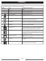 6
6
-
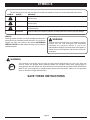 7
7
-
 8
8
-
 9
9
-
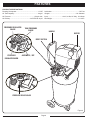 10
10
-
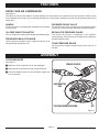 11
11
-
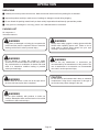 12
12
-
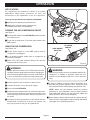 13
13
-
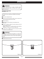 14
14
-
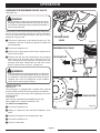 15
15
-
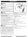 16
16
-
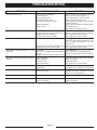 17
17
-
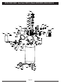 18
18
-
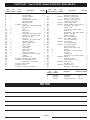 19
19
-
 20
20
-
 21
21
-
 22
22
-
 23
23
-
 24
24
-
 25
25
-
 26
26
-
 27
27
-
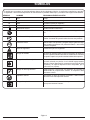 28
28
-
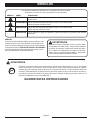 29
29
-
 30
30
-
 31
31
-
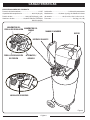 32
32
-
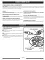 33
33
-
 34
34
-
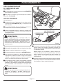 35
35
-
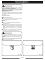 36
36
-
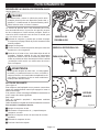 37
37
-
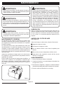 38
38
-
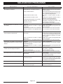 39
39
-
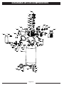 40
40
-
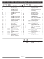 41
41
-
 42
42
-
 43
43
-
 44
44


Husky F226VWD Manual de usuario
- Categoría
- Compresores de aire
- Tipo
- Manual de usuario
en otros idiomas
- English: Husky F226VWD User manual