
Digital Sound Projector™
Owner’s Manual
English
for Europe, Asia, Africa, Oceania,
and Latin America

2 En
What you can do with this unit
Make sure you read precaution in “Safety and Accessory Information” (separate booklet) carefully before using this unit.
Audio/video device
TV Blu-ray disc player
Preparation
Installing the unit
Connections/Basic settings
Connecting a satellite/
cable TV tuner
Connecting a Blu-ray
disc player
Operating this unit using a TV’s
remote control (HDMI control)
Playback
Basic operation for playback
Various functions
HDMI control (link) function TV remote repeater function
UniVolume IntelliBeam
System memory Eco function
p. 11
p. 19 p. 18
p. 30
p. 32
p. 30 p. 12
p. 40 p. 23
p. 28 p. 41

3 En
Game console
iPod or USB device
over a USB
connection
(YSP-4300 only)
iPod or computer
over a wireless
connection
FM tuning
(YSP-4300 only)
Preparing the remote control
Connecting a TV
Connecting a game
console
Connecting an indoor
FM antenna
Setting appropriate surround effects automatically (IntelliBeam)
Playing an iPod or
USB device
Playing an iPod or
computer
FM tuning
(YSP-4300 only)
CINEMA DSP Compressed Music Enhancer
Target playback Wireless playback for an iPod or computer
Playback for an iPod or USB device over a
USB connection (YSP-4300 only)
FM tuner (YSP-4300 only)
p. 16
p. 18
p. 19 p. 20
p. 23
p. 50 p. 50 p. 44
p. 34 p. 33
p. 39 p. 50
p. 50 p. 44

4 En
Contents
PREPARATION
Controls and functions...............................................5
Center unit front panel (front, top)........................................... 5
Center unit rear panel (back) .................................................. 6
Subwoofer rear panel (back)................................................... 7
Front panel display.................................................................. 8
Remote control........................................................................ 9
Installation .................................................................11
Recommended installation.................................................... 11
Conditions that make it difficult for sound beams to achieve
surround sound ..................................................................... 11
Enjoying surround effects regardless of conditions
(My Surround)....................................................................... 12
If the TV remote control does not work properly after the center
unit is installed (TV Remote Repeater function) ................... 12
If the center unit cannot be installed on a TV stand
(increasing the height of the center unit)............................... 12
Positioning the subwoofer on its side.................................... 13
Installing this unit .................................................................. 14
Preparing remote control ..............................................16
Installing the batteries........................................................... 16
Operation range .................................................................... 16
Connections ..............................................................17
Connecting a TV and a Blu-ray disc player...................18
Connecting a game console or
satellite/cable TV tuner .................................................19
Connecting the FM antenna (YSP-4300 only) ..............20
Connecting the wireless subwoofer ..............................20
Initial settings............................................................21
Establishing a wireless connection ...............................21
Group IDs.............................................................................. 21
Displaying the menu screen on the TV .........................21
Selecting the language for menu display ......................22
Auto setup for appropriate surround effects
(IntelliBeam)..................................................................23
Installing the IntelliBeam microphone ................................... 23
Using AUTO SETUP (IntelliBeam)........................................ 24
Saving this unit’s settings to system memory ....................... 28
Operating the unit by TV’s remote control
(HDMI control)...............................................................30
PLAYBACK
Playback features......................................................32
Basic operation for playback.........................................32
Enjoying sound based on your preference ...................33
Switching between surround playback, stereo playback, and
target playback modes.......................................................... 33
Playing back digitally compressed formats (MP3, WMA, etc.)
with enriched sound (Compressed Music Enhancer) ........... 33
Adjust volume for each channel............................................ 33
Enjoying realistic surround sounds (CINEMA DSP) ............. 34
Changing the audio output method for surround playback ... 36
Setting the surround decoder................................................ 38
Delivering sound to a specified location
(Target playback mode)........................................................ 39
Using useful features ....................................................40
Automatic volume level adjustment (UniVolume) ................. 40
Saving energy with the Eco function..................................... 41
Switching information displayed in the front panel display.... 41
Settings each input source (Option menu)............................ 42
FM tuning (YSP-4300 only)...........................................44
Tuning into the desired FM station (Frequency tuning) ........ 44
Receiving weak signal ...........................................................45
Registering FM stations and tuning in (Preset tuning)...........45
Displaying the Radio Data System information
(Europe model only) ..............................................................48
Playing music stored on an iPod or computer
over a wireless connection........................................... 50
Playing music stored on an iPod or USB device
over a USB connection (YSP-4300 only) ..................... 50
Connecting an iPod ...............................................................50
Operating an iPod via the TV screen.....................................51
Using the iPod to control operation .......................................54
Charging the iPod..................................................................55
Connecting a USB device......................................................56
Operating a USB device via the TV screen ...........................57
SETTINGS
Setup menu............................................................... 60
Setting the setup menu ................................................ 60
Setup menu list ............................................................ 61
BEAM settings.............................................................. 62
HORIZONTAL ANGLE ..........................................................62
BEAM TRAVEL LENGTH......................................................62
FOCAL LENGTH ...................................................................62
IMAGE LOCATION................................................................63
CHANNEL OUT.....................................................................63
SOUND settings........................................................... 64
SPEAKER LEVEL .................................................................64
Adaptive DRC........................................................................64
DYNAMIC RANGE ................................................................65
Dolby PLIIx PARAMETER.....................................................65
HDMI setup .................................................................. 65
HDMI CONTROL...................................................................65
HDMI AUDIO OUT.................................................................65
TV INPUT ..............................................................................65
AirWired settings .......................................................... 66
iPod INTERLOCK..................................................................66
GROUP ID.............................................................................66
DISPLAY settings......................................................... 67
DIMMER ................................................................................67
OSD LANGUAGE ..................................................................67
DISTANCE UNIT ...................................................................67
INFORMATION settings............................................... 67
AUDIO ...................................................................................67
VIDEO ...................................................................................67
SYSTEM................................................................................67
Advanced setup........................................................ 68
TROUBLESHOOTING
Troubleshooting ....................................................... 70
General..................................................................................70
FM tuner (YSP-4300 only).....................................................72
USB device (YSP-4300 only) ................................................72
Remote control ......................................................................72
Messages .................................................................. 73
iPod (when connected via USB jack)/
USB device (YSP-4300 only) ................................................73
APPENDIX
Glossary.................................................................... 74
Specifications........................................................... 76
Available signal information ......................................... 78
Index.......................................................................... 79
About this manual
• In this manual, operations that can be performed using either the front panel keys or the remote control are explained using the
remote control.
• In this manual, iPod(s), iPhone(s), and iPad(s) are hereafter referred to collectively as iPod(s).
•
y indicates a tip for your operation.
• Notes contain important information and operating instructions.
• In this manual, the YSP-CU4300 center unit is used for illustrative purposes. Illustrations for both the YSP-CU4300 and
YSP-CU3300 are provided where necessary.

5 En
PREPARATION PLAYBACK SETTINGS
TROUBLESHOOTING
APPENDIX
PREPARATION
Controls and functions
1 Remote control sensor
Receives infrared signals from the remote control (☞p. 9).
2 Remote control sensor of a TV
Receives infrared signals from the TV remote control when
the TV Remote Repeater function is enabled (☞p. 12).
3 Wireless module
Receives and sends wireless signals. Do not place metal
objects in front of the wireless module as they may interfere
with the wireless module’s ability to receive and send
wireless signals.
4 Front panel display
Shows information about the operational status of this unit
(☞p. 8).
5 USB jack (YSP-4300 only)
Enables connection of a USB device (☞p. 50, 56).
6 SURROUND indicator
Lights up according to the input signal.
7 STATUS indicator
Lights up when the power is turned on, and goes off in the
standby mode.
8 INPUT key
Selects the playback component (☞p. 32).
9 VOLUME (+/-) key
Adjusts the volume of the unit (☞p. 32).
0 key
Turns on the unit or set it to the standby mode.
Center unit front panel (front, top)
12 3 4 5 67
890
YSP-CU4300
467
890
12 3
YSP-CU3300
Displayed
color
Input signal
Blue Following surround audio signal formats:
Dolby TrueHD, Dolby Digital Plus, DTS-HD
Master Audio, DTS-HD High Resolution,
Multi-channel Linear PCM
Orange Surround audio signal other than above
Off Stereo/monaural audio signal or no signal
In the standby mode, this unit consumes a small amount of
power in order to search for HDMI signals or to receive
infrared signals from the remote control.
Note

Controls and functions
6 En
1 FM ANTENNA jack (YSP-4300 only)
Connect an FM antenna (☞p. 20).
2 INTELLIBEAM MIC jack
Connect the supplied IntelliBeam microphone (☞p. 24).
3 INPUT ANALOG L/R jacks
For connecting analog cable to the external components
(☞p. 19).
4 AUX INPUT DIGITAL jack
For connecting a coaxial digital audio cable to the external
components (☞p. 19).
5 IR IN
1)
/OUT jacks
Control expansion jacks for commercial use only.
6 HDMI OUT (ARC) jack
For connecting an HDMI compatible TV and monitor
(☞p. 18).
7 HDMI IN jacks
For connecting HDMI compatible Blu-ray disc player,
satellite and cable TV tuner and game console (☞p. 18, 19).
8 RS-232C terminal
A control expansion terminal for commercial use only.
9 INPUT DIGITAL TV/OPTICAL jacks
For connecting an optical cable to the external components
(☞p. 18, 19).
0 TV Remote Repeater
Receives signals from a TV remote control via the front of
the center unit and transmits those signals to the TV when the
center unit obstructs the remote control sensor on the TV
(☞p. 12).
a Power cable
For connecting to an AC wall outlet (☞p. 18).
Center unit rear panel (back)
12 3 54
6789
0A
Only for Europe and China models
1) y

Controls and functions
7 En
PREPARATION PLAYBACK SETTINGS
TROUBLESHOOTING
APPENDIX
1 Group ID switches
When the center unit and subwoofer are connected
wirelessly, sound is output from the subwoofer (AirWired).
For a wireless connection, use the same group ID as the
center unit and YIT-W12TX (☞p. 20).
2 LINK indicator
Shows wireless connection status (☞p. 21).
3 Heat discharge unit
Discharges heat generated inside the subwoofer. Do not
cover the heat discharge unit.
4 Power cable
For connecting to an AC wall outlet (☞p. 20).
Subwoofer rear panel (back)
A
B
C
1
2
3
LINK
A
B
C
1
2
3
LINK
1
2
4
3

Controls and functions
8 En
1 Playback indicators (YSP-4300 only)
Lights while music stored on an iPod or USB device
connected to the USB jack is playing (☞p. 50, 56).
2 TARGET indicator
Lights when target playback mode enabled (☞p. 39).
3 Tuner indicators (YSP-4300 only)
Lights up when this unit is tuned into an FM station
(☞p. 44).
4 REPEATER indicator
Lights when the TV Remote Repeater function is enabled
(☞p. 10).
5 Wireless indicators
TX Lights while the connection to the subwoofer is being
established (☞p. 20).
RX Lights while the connection to YIT-W12TX is being
established. For details of YIT-W12TX, refer to
“Safety and Accessory Information” (separate
booklet).
6 VOL indicator
Indicates the current volume level (☞p. 32).
7 HDMI indicator
Lights up when HDMI signals are input.
8 CINEMA DSP indicator
Lights up when a sound field program is selected (☞p. 34).
9 UNIVOLUME indicator
Lights up when the UniVolume function is enabled (☞p. 40).
0 Radio Data System indicators (Europe model
only)
Lights according to the current Radio Data System status
(☞p. 48).
a ENHANCER indicator
Lights up when the Compressed Music Enhancer function is
enabled (☞p. 33).
b Multi information display
Display playback device input source and surround
information (☞p. 41). Displays settings and information as
alphanumeric characters.
Front panel display
1)
12 3 45 6
789
0A B
Note that the front panel display turns off when the Eco function is
enabled and remains off unless an operation is performed.
1) y

Controls and functions
9 En
PREPARATION PLAYBACK SETTINGS
TROUBLESHOOTING
APPENDIX
1 BEAM key
Switches the sound beam output method (☞p. 37).
2 ENHANCER key
Turns Compressed Music Enhancer to on or off (☞p. 33).
3 Input selector keys
Select the playback component (☞p. 32).
4 CINEMA DSP program keys
When playback is in surround playback mode, select the
CINEMA DSP programs (☞p. 34).
5 SURROUND key
Switches to surround playback mode (☞p. 34).
6 S/T/W/X keys, ENTER key
Change the setting (☞p. 60).
7 SETUP key
Displays the setup menu (☞p. 60).
8 OPTION key
Displays the option menu for each input source (☞p. 42).
9 TARGET key
Switches to target playback mode (☞p. 39).
0 SUBWOOFER (+/-) key
Adjusts the volume of the subwoofer.
Remote control
1
I
H
J
K
L
M
N
O
P
Q
2
3
4
5
C
6
7
8
9
0
A
B
E
F
G
D
Infrared signal transmitter
O
P
E
YSP-3300

Controls and functions
10 En
a MUTE key
Mute the sound (☞p. 32).
b SYSTEM MEMORY keys
Saves IntelliBeam measurements, speaker volume, and other
settings (☞p. 28).
c FM key (YSP-4300 only)
Switches this unit’s input source to FM radio.
d Tuner operation keys (YSP-4300 only)
Press to select or register an FM station (☞p. 44).
e CH LEVEL key
Adjusts the volume balance during playback (☞p. 33).
f USB key (YSP-4300 only)
Switches this unit’s input source to USB (☞p. 50).
g Playback operation keys (YSP-4300 only)
Perform playback operations for music stored on an iPod or
USB device (☞p. 50).
h Transmission indicator
Lights with operation using this unit’s remote control.
i key
Turns on the unit or set it to the standby mode (☞p. 32).
j STEREO key
Switches to stereo playback mode (☞p. 33).
k RETURN key
Returns to the previous menu screen.
l INFO key
Switches the information display on the front panel as
follows.
• Input: Input name
• Beam: Beam mode setting (stereo, beam stereo, target, or
surround playback mode)
• Decoder: Sound signal decoder currently selected
• Cinema DSP: Sound field program of CINEMA DSP
(only in surround playback mode)
Information displayed varies according to the selected input
source (☞p. 41, 53, 55, 58).
This key is also used to select a desired Radio Data System
display mode (Europe model only) (☞p. 48).
m UNIVOLUME key
Turns the UniVolume function on or off (☞p. 40).
n VOLUME (+/-) key
Adjusts the volume of the unit (☞p. 32).
o ECO key
Turns the Eco function on or off (☞p. 41).
p REMOTE REPEATER key
Turns the TV Remote Repeater function on or off (☞p. 12).
q iPod CONTROL key (YSP-4300 only)
Press to display the iPod browse/playback screen on the TV
(☞p. 53).
Demo mode
This unit outputs sound beam down-mixed to 1 channel
moving horizontally to right and left. By this function, you
can feel how sound beam is output from this unit.
To activate Demo mode:
1 Press the TARGET key on the remote control.
2 Press the CINEMA DSP OFF key.
“AUTO DEMO” is shown in the front panel display when
demo mode starts.
To exit demo mode, press the CINEMA DSP OFF key
again. The display returns to target playback mode display.

11 En
PREPARATION PLAYBACK SETTINGS
TROUBLESHOOTING
APPENDIX
Installation
To achieve desired surround sound effects, install this unit where there are no objects such as furniture obstructing the path of sound
waves, referred to as “sound beam(s)” in this manual (☞p. 14). Depending on the location where the unit is installed, it may be easier to
connect external devices such as a TV first. See “Connections” (☞p. 17).
Some TVs have sensors such as the motion sensor or signal transmitter for 3D glasses in front. Installing the center unit may interrupt
the sensors or signal transmitter from functioning. Set the center unit away from your TV.
Center unit
• Install the center unit in the center of the left and right walls.
• Place the center unit on a TV stand in front of the TV.
Use the TV Remote Repeater function if the center unit
obstructs the remote control sensor on the TV (☞p. 12).
Increase the height of the center unit if the TV stand is too high
for center unit installation (☞p. 12).
• The listening position (such as sofa, etc.) should be located at
the front of the center unit.
• The distance between the listening position and the center unit
should be more than 1.8 m.
• This unit can be mounted on a wall using WALL MOUNT
BRACKET SPM-K20 (option). Refer to the SPM-K20 Install
Manual and SPM-K20 Information for YSP-CU4300/
YSP-CU3300.
Subwoofer
• To prevent sound reflecting off of walls, angle the subwoofer
slightly toward the center of the room.
• When installing the subwoofer on a rack, be sure the rack is
strong enough to support the subwoofer and that it leaves
sufficient space for heat discharge.
• The center unit and subwoofer communicate wirelessly.
Subwoofer performance may be affected if the subwoofer is
placed on a metal rack, or if there is a metal plate between the
subwoofer and the center unit.
• The subwoofer can also be placed on its side (☞p. 13).
This unit creates surround sound by reflecting projected sound beams off the walls of your listening room. The surround sound effects
produced by this unit may not be sufficient when this unit is installed in the following locations.
• Rooms with walls inadequate for reflecting sound beams
• Rooms with acoustically absorbent walls
• Rooms with measurements outside the following range:
W (3 to 7 m) × H (2 to 3.5 m) × D (3 to 7 m)
• Rooms with less than 1.8 m from the listening position to this
unit
• Rooms where objects such as furniture are likely to obstruct
the path of sound beams
• Rooms where the listening position is close to the walls
• Rooms where the listening position is not in front of this unit
Recommended installation
Notes
• This unit requires sufficient space for heat discharge.
– A minimum of 5 cm above and behind and 1 cm to the sides of the center unit
– A minimum of 20 cm above, behind, and to the sides of the subwoofer
Do not cover the subwoofer heat discharge unit on the back of the subwoofer.
• Be sure to install this unit where it does not fall subject to vibrations, such as from an earthquake, and where it is out of the reach of children.
• When using a cathode-ray tube (CRT) TV, do not install this unit directly above your TV.
• If the picture on your TV screen becomes blurred or distorted, we recommend moving this unit away from your TV.
Center unit Subwoofer
Conditions that make it difficult for sound beams to achieve surround sound

Installation
12 En
The My Surround function creates rich surround sound effects in rooms with less than optimal surround sound conditions (☞p. 11). See
“Changing the audio output method for surround playback” (☞p. 36, 37) for more information.
The TV may not respond to commands from
its remote control if the center unit obstructs
the remote control sensor on the TV. Should
this occur, press the REMOTE
REPEATER key on this unit’s remote
control more than 3 seconds to set the TV
Remote Repeater function to enable. The
REPEATER indicator on the front panel
display will light.
When the TV remote control is aimed at the
center unit’s remote control sensor, the TV
Remote Repeater on the back of this unit
transmits signals from the TV remote control
to the TV.
Signals from the TV remote control can be transmitted to the TV while this unit is in standby mode.
This function can be used while the TV remote control is using infrared signals.
In most cases, the center unit can be placed on a TV stand. The supplied spacers can be attached to increase the height of the unit if
necessary. Attach both the left and right spacers to the unit.
Removing the spacers
Pull the spacers straight up.
Enjoying surround effects regardless of conditions (My Surround)
If the TV remote control does not work properly after the center unit is installed (TV Remote
Repeater function)
Note
If the center unit cannot be installed on a TV stand (increasing the height of the center unit)
TV remote control
sensor
TV Remote Repeater
TV remote control
Align the protrusions on the back of the spacer with the
mounting holes on the bottom of the center unit and press
the spacer firmly into place.
Spacer
Protrusions
Mounting holes
Bottom of the center unit
Pull the spacer straight up.

Installation
13 En
PREPARATION PLAYBACK SETTINGS
TROUBLESHOOTING
APPENDIX
The subwoofer can be laid on its side when positioned on a rack.
Positioning the subwoofer on its side
Removing the legs
and sheets
Turn clockwise
Turn counterclockwise
Attaching the legs
and sheets
Leg
Sheet

Installation
14 En
This unit outputs sound beam as shown in the illustrations below. Install this unit where there are no obstacles such as furniture
obstructing the path of sound beams. Otherwise, the desired surround sound effects may not be achieved.
You may install this unit in parallel with the wall or in the corner.
Parallel installation
Install this unit as close to the exact center of the wall as possible.
Ideal installation condition
Install this unit as close to the exact front of your normal listening position as possible.
The distance between listening position and the unit should be more than 1.8 m.
Installing this unit
Parallel installation
Install this unit in the exact center of the wall when it is measured
from the left and right corners.
Corner installation
Install this unit in the corner at a 40° to 50° angle from the
adjacent walls.
Objects, such as
furniture
40° to 50°
Parallel installation
(with 5Beam)
Corner installation
(with Stereo+3Beam)
Objects, such as furniture
More
than
1.8 m
More
than
1.8 m

Installation
15 En
PREPARATION PLAYBACK SETTINGS
TROUBLESHOOTING
APPENDIX
Installing in a non-square room
Install this unit so that the sound beams can be reflected off the walls.
Example for installing the unit in living room
Irregularly shaped rooms with solid walls on all side
Irregularly shaped rooms that are open to a hallway on one side
• As sound beams normally pass through tables, tables are not
obstacles. And a cupboard installed facing the wall reflects
sounds.
• In a case of the listening room as shown in the right illustration,
adjusting the position of the right channel after AUTO SETUP
(☞p. 23) enables to achieve more desired surround sound
effects (☞p. 63).
• As the curtains absorb sounds, the sound features of the
listening room is different from the case with the curtain opened
and the case with the curtain closed. Using saving settings
function enables to save the best settings for each case of
listening room (☞p. 28).
Objects, such as
furniture

Installation
16 En
Before installing batteries or using the remote control, be sure to read battery and remote control precautions in “Safety and Accessory
Information” (separate booklet).
Preparing remote control
Installing the batteries
Battery × 2
(AAA, R03, UM-4)
Pull up on the
latch to release
the cover
Insert the
protrusions
into the slots
and close the
cover
Operation range
Within 6 m

17 En
PREPARATION PLAYBACK SETTINGS
TROUBLESHOOTING
APPENDIX
Connections
When external devices such as a TV, Blu-ray disc player, and/or game console are connected, audio
and video signals are transmitted as shown below.
Audio connection
Video connection
Audio and video connection
This unit: Plays audio from TV broadcasts, Blu-ray discs, etc.
Game console
(HDMI compatible)
Satellite and cable TV tuner
(not HDMI compatible)
TV: Plays video from TV
broadcasts, Blu-ray disc
player, etc.
Blu-ray disc player
HDMI cable
HDMI cable
HDMI cable
Optical cable
Use to connect a TV that does not
support audio return channel
(ARC) to this unit (☞p. 18).
Composite video cable
Optical cable

Connections
18 En
For the cable connection, follow the procedure below.
Connecting a TV and a Blu-ray disc player
1
HDMI cable (optional)
Input the digital audio/video signals
of the Blu-ray disc player to this unit.
2
HDMI cable (optional)
The digital video of the Blu-ray disc
player is reflected on TV.
3
Optical cable (supplied)
Play back digital sounds of TV on
this unit.
• Do not connect the power cable until all connections are completed.
• Do not use excessive force when inserting the cable plug. Doing so may damage the cable plug and/or jack.
HDMI INPUT
123
HDMI
OUTPUT
OPTICAL
OUTPUT
To AC wall outlet
Blu-ray disc player
1. Remove the cap
2. Check the direction of
the plug
TV
Video signals
Audio signals
1
2
3
1)
Audio return channel (ARC) supported TV
• Connect an HDMI cable to the audio return channel supported jack
(the jack with “ARC” indicated) on TV. In this case, you do not need
to connect an optical cable.
• Activate the HDMI control function of this unit so as to activate the
audio return channel (ARC) (☞p. 65).
What is audio return channel (ARC)?
A function transmits digital audio signal output from TV to this unit
through an HDMI cable. By this function, an optical cable to connect TV
and this unit is not needed.
1) y

Connections
19 En
PREPARATION PLAYBACK SETTINGS
TROUBLESHOOTING
APPENDIX
Connecting a game console or satellite/cable TV tuner
External device (example) Connecting cable
HDMI compatible
1 Satellite/cable TV tuner
HDMI cable (optional)
2 Game console
HDMI cable (optional)
3 Game console
HDMI cable (optional)
not HDMI compatible
4 Satellite/cable TV tuner
Optical cable (supplied)
Composite video cable (optional)
5 Game console
RCA stereo cable (optional)
Composite video cable (optional)
HDMI
OUTPUT
HDMI
OUTPUT
HDMI
OUTPUT
OPTICAL
OUTPUT
VIDEO
OUTPUT
VIDEO
INPUT
VIDEO
INPUT
VIDEO
OUTPUT
ANALOG
OUTPUT
RL
Video signals
Audio signals
TV
1
4
2 3
5
To AC wall outlet
2)
To connect a device with an AUX output jack, connect its AUX output
jack to the AUX INPUT DIGITAL (coaxial) jack on this unit via a
commercial coaxial digital audio cable.
2) y

Connections
20 En
Connect the supplied FM antenna via the FM ANTENNA jack.
To connect the subwoofer (NS-WSW160) to the center unit
wirelessly (AirWired), the same group ID must be assigned to the
center unit and subwoofer. The default group ID for both
components is A1, enabling wireless connection by simply
plugging the subwoofer's power cable into an electrical outlet.
When using the transmitter (YIT-W12TX)
1)
, the same group ID
must be assigned to the center unit and subwoofer. The default
group ID of YIT-W12TX is A1.
The LINK indicator lights when the subwoofer is on and the
subwoofer and center unit are connected wirelessly.
When the center unit enters standby mode, the subwoofer and
LINK indicator turn off.
Connecting the FM antenna (YSP-4300 only)
Connecting the wireless subwoofer
FM antenna
y Tip
See page 21 for more information on group ID.
A
B
C
1
2
3
LINK
A
B
C
1
2
3
LINK
Group ID switches
LINK indicator
Blinks: Establishing
connection
Lights: Connection
established
To AC wall outlet
For details of YIT-W12TX, refer to “Safety and Accessory Information”
(separate booklet).
1) y

21 En
PREPARATION PLAYBACK SETTINGS
TROUBLESHOOTING
APPENDIX
Initial settings
Yamaha’s proprietary AirWired technology enables the wireless
connection of the center unit and subwoofer. Wireless connection
of the subwoofer allows for subwoofer installation without
concern for cables. When the transmitter (YIT-W12TX) is used,
iPods or computers can be connected wirelessly to play music
stored on these devices through this unit.
For details of YIT-W12TX, refer to “Safety and Accessory
Information” (separate booklet).
When playing content from a TV or Blu-ray disc player, the
center unit transmits audio signals that are received by the
subwoofer. When YIT-W12TX is used to play songs stored on an
iPod or computer, YIT-W12TX sends audio signals that are
received by the center unit and subwoofer.
The same group ID must be assigned to all components. By
default, the center unit, subwoofer, and YIT-W12TX are assigned
a group ID of A1. This group ID does not need to be changed.
The center unit, subwoofer, and YIT-W12TX can be assigned a
group ID from three possible sets: A1–A3, B1–B3, C1–C3.
Use set C1–C3 when playing music stored on a computer via
YIT-W12TX. For details of YIT-W12TX, refer to “Safety and
Accessory Information” (separate booklet).
In all other cases, select a group ID from set A1–A3, B1–B3, or
C1–C3 to achieve a stable wireless connection.
To prevent wireless connection of another AirWired Yamaha
sound system or device installed near this unit or the
YIT-W12TX, assign a different group ID to this unit and the
YIT-W12TX.
Changing the group ID
Center unit
Change the group ID from “GROUP ID” in the setup menu
(☞p. 66).
Subwoofer
Use the group ID switches on the back of the subwoofer to
change the group ID (☞p. 20).
YIT-W12TX
Use the group ID switches on the side of YIT-W12TX to change
the group ID. For details of YIT-W12TX, refer to “Safety and
Accessory Information” (separate booklet).
Visual operation of this unit
is possible by displaying its
menu screen on the TV.
Use the button for switching
between input sources on the
TV’s remote control to
select this unit.
When this unit and the TV
are connected as shown
below, select “HDMI 1”.
The menu display
The setup menu is displayed on the TV screen when the SETUP
key is pressed. When the TV is receiving HDMI signals, the
menu is superimposed over video content. Press the SETUP key a
second time to cancel setup menu display.
Establishing a wireless connection
Group IDs
Displaying the menu screen on the
TV
TV remote control (example)
Switch
input
sources
HDMI INPUT
123
TV
this unit
SETUP MENU
BEAM
SOUND
HDMI
AirWired
DISPLAY
INFORMATION
IntelliBeam
HORIZONTAL ANGLE
BEAM TRAVEL LENGTH
FOCAL LENGTH
IMAGE LOCATION
CHANNEL OUT
The setup menu (☞p. 60) can only be displayed on a TV screen. It
cannot be shown in the front panel display.
Note

Initial settings
22 En
SETUP
S/T
ENTER
Selecting the language for menu
display
1
Turn the unit and TV on.
2
Switch the TV’s input to display video
input from this unit (☞p. 21).
3
Press and hold the SETUP key until the
“OSD LANGUAGE” menu appears on your
TV.
1)
4
Press the S/T key to select the desired
language.
Selectable item: , ENGLISH, DEUTSCH,
FRANÇAIS, ESPAÑOL, ITALIANO, NEDERLANDS,
РУССКИЙ, SVENSKA
Initial setting: ENGLISH
5
Press the SETUP key to exit the setup
menu.
OSD LANGUAGE
ENGLISH
DEUTSCH
FRANÇAIS
ESPAÑOL
ITALIANO
NEDERLAND
РУССКИЙ
SVENSKA
When the screen is not displayed
Confirm the following cases.
– The HDMI input jack of your TV and the HDMI OUT (ARC) jack
of the unit are connected.
– The input of your TV is set to “HDMI 1 (example)”.
1) y

Initial settings
23 En
PREPARATION PLAYBACK SETTINGS
TROUBLESHOOTING
APPENDIX
Due to differences in room sizes and shapes, positioning of this
unit, and the lifestyle of users, settings for each channel must be
adjusted in order for this unit to provide the optimal listening
experience.
This unit is equipped with IntelliBeam, which automatically
adjusts settings for each channel. IntelliBeam offers two features,
“beam optimization” and “sound optimization”.
Beam optimization:
This feature optimizes the beam angle so that the parameter best
matches your listening environment.
Sound optimization:
This feature optimizes the beam delay, volume, and quality so
that the parameters best match your listening environment.
This unit performs these two automatic optimizations with the aid
of the supplied IntelliBeam microphone.
2)
Make sure that there are no obstacles between the IntelliBeam
microphone and the walls in your listening room as these objects
obstruct the path of sound beams.
However, any objects that are in contact with the walls will be
regarded as a protruding part of the walls.
Auto setup for appropriate
surround effects (IntelliBeam)
Installing the IntelliBeam microphone
Place the IntelliBeam microphone at your
normal listening position.
• Use the supplied cardboard microphone stand or a tripod to
place the IntelliBeam microphone at the same height as your
ears would be when you are seated.
• Position the IntelliBeam microphone so that it is parallel with
the floor.
• The AUTO SETUP procedure may not be run successfully if this
unit is installed in one of the rooms described in “Conditions that
make it difficult for sound beams to achieve surround sound” on
page 11. The My Surround function can be used to enjoy rich
surround sound in these types of rooms as well. See “Changing
the audio output method for surround playback” (☞ p. 36, 37) for
more information.
• Do not connect the IntelliBeam microphone to an extension
cable as doing so may result in an inaccurate sound optimization.
• After you have completed the AUTO SETUP procedure, be sure
to disconnect the IntelliBeam microphone.
• The IntelliBeam microphone is sensitive to heat.
– Keep the IntelliBeam microphone away from direct sunlight.
– Do not place the IntelliBeam microphone on top of this unit.
Notes
Assembling the supplied cardboard
microphone stand
123
45
Remove
Fit in
Run through
Place
horizontally
Fit in
IntelliBeam microphone Upper limit
Within 1 m
Center height of
this unit
Cardboard
microphone stand
Within 1 m
Listening
position
1.8 m or more
Lower limit
Center line
IntelliBeam
microphone
Cardboard microphone stand
• “BEAM+SOUND OPTIMIZE” screen appears automatically when
the IntelliBeam microphone is connected. “BEAM OPTIMIZE
ONLY” or “SOUND OPTIMIZE ONLY” can be selected separately
in the setup menu (☞p. 26).
• Up to three sets of automatically configured settings can be stored in
this unit’s memory (☞p. 28). You can save the several data depending
on listening room and you can change the setting conveniently.
2) y

Initial settings
24 En
ENTER
RETURN
SYSTEM
MEMORY
Using AUTO SETUP (IntelliBeam)
1
Turn the unit and your TV on.
2
Switch TV input to display video input
from this unit (☞p. 21).
3
Connect the IntelliBeam microphone to the
INTELLIBEAM MIC jack on the rear of the
unit.
• It is normal for loud test tones to be output during the AUTO
SETUP procedure. Make sure that there are no children around
in the listening room while the AUTO SETUP procedure is in
progress.
• If there are curtains in your listening room, we recommend
following the procedure below.
1 Open the curtains to improve sound reflection.
2 Run “BEAM OPTIMIZE ONLY” (☞p. 26).
3 Close the curtains.
4 Run “SOUND OPTIMIZE ONLY” (☞p. 26).
• Make sure that your listening room is as quiet as possible. For
accurate measurement, turn off air conditioner or other devices
that make noises.
Notes
IntelliBeam microphone

Initial settings
25 En
PREPARATION PLAYBACK SETTINGS
TROUBLESHOOTING
APPENDIX
The screen below is displayed after connecting
IntelliBeam microphone to the unit.
1)
4
Press the ENTER key to start the AUTO
SETUP procedure and then leave the room
within 10 seconds.
2)
The screen automatically changes during the AUTO
SETUP procedure.
If the AUTO SETUP procedure is complete, this unit
rings the chimes.
3)
AUTO SETUP
(PREPARATION & CHECK)
Please connect the MIC.
Please place the MIC at least
1.8m/6ft away from Sound Pro-
jector. The MIC should be set
at ear level when seated.
Measurement takes about 3min.
After [ENTER] is pressed,
please leave the room.
[ENTER]:Start [RETURN]:Cancel
Follow the instructions below and then leave the room. If you remain
in the room, you may obstruct the beam, or the microphone may pick
up any sounds you make, possibly resulting in improper
configuration of settings.
Note
ENVIRONMENT CHECK: Success
BEAM MODE: 5Beam/Plus2
SHOW RESULT
MESUREMENT COMPLETE.
[ENTER]:Save set-up.
[RETURN]:Do not save set-up.
Will begin in 10 sec.
Please leave the room
----------
AUTO SETUP START
[RETURN]:Cancel
(After 3 min.)
5
Press the ENTER key to confirm the
results.
4)
Measurement results are applied to this unit.
• The measurement results are stored in the internal
memory of this unit until you run the AUTO SETUP
procedure again or configure the settings manually.
• You can save the several measurement results pressing
the SYSTEM MEMORY key (☞p. 28).
6
Remove the IntelliBeam microphone.
The “AUTO SETUP COMPLETE” screen closes.
5)
Keep the IntelliBeam microphone in a safe place.
AUTO SETUP COMPLETE
Please remove the MIC
from Sound Projector
and the listening position.
Press [SYSTEM MEMORY] key
to save set-up in the memory.
“BEAM+SOUND OPTIMIZE” is selected automatically. When you
perform “BEAM OPTIMIZE ONLY” or “SOUND OPTIMIZE ONLY”
only, refer to “AUTO SETUP via setup menu” (☞p. 26).
• Wait outside the room during the AUTO SETUP procedure.
Remaining in the room after the AUTO SETUP process begins may
result in the improper configuration of settings as your body may
obstruct sound beams or the microphone may pick up sounds you
make inadvertently.
• The AUTO SETUP procedure takes about 3 minutes.
• To cancel the AUTO SETUP procedure after it is started, press the
RETURN key.
If an error occurs, an error buzzer sounds and an error message is
displayed. For details on error messages, see “If an error message is
displayed” (☞p. 27).
• If “ENVIRONMENT CHECK:Failure” is displayed, accurate
measurement may not have been possible. See “ERROR-E1” under
“Error messages” (☞p. 27) for the remedy to this most common error.
Press the RETURN key and begin measurement again.
• Depending on the environment of your listening room, the front left
and right beam angles and left and right surround beam angles may be
set to the same value even if “BEAM MODE :5Beam” is displayed as
a result.
If you do not want to apply the results, press RETURN key.
When AUTO SETUP is performed from the setup menu, the menu
selection screen of the setup menu appears.
1) y
2) y
3) y
4) y
5) y

Initial settings
26 En
S/T
SETUP
RETURN
ENTER
X
AUTO SETUP via setup menu
1
Place the IntelliBeam microphone at your
normal listening position, and press the
SETUP key.
See “Installing the IntelliBeam microphone” (☞p. 23) for
instructions on positioning the IntelliBeam microphone.
2
Press the S/T key to select “BEAM” and
then press the X key.
1)
3
Press the S/T key to select “IntelliBeam”
and then press the X key.
1)
4
Press the S/T key to select one of the
items below and then press the X key.
1)
Select Item:
“BEAM+SOUND OPTIMIZE”
(Beam optimization and sound optimization)
Select this optimization feature if you make settings for the
first time. This menu takes about 3 minutes.
“BEAM OPTIMIZE ONLY”
(Beam optimization only)
Use to optimize the beam angle so that the parameter best
matches your listening environment. This menu takes about
1 minute.
“SOUND OPTIMIZE ONLY”
(Sound optimization only)
Use to optimize the beam delay, volume, and quality so that
the parameters best match your listening environment. This
menu takes about 2 minutes.
You must optimize the beam angle with “BEAM
OPTIMIZE ONLY” before starting “SOUND OPTIMIZE
ONLY”. Select this optimization feature in the following
cases:
• If you have opened or closed the curtains in your
listening room before using this unit
• If you have manually set the beam angle.
5
Connect the IntelliBeam microphone to
this unit after “AUTO SETUP
(PREPARATION & CHECK)” screen is
displayed.
For the details on connecting IntelliBeam microphone,
refer to “Using AUTO SETUP (IntelliBeam)” (☞ p. 24).
6
Follow steps 4, 5, and 6 under “Using
AUTO SETUP (IntelliBeam)” to configure
settings, and then remove the microphone.
The ENTER key performs the same function as the X key.
1) y

Initial settings
27 En
PREPARATION PLAYBACK SETTINGS
TROUBLESHOOTING
APPENDIX
If an error message is displayed on the TV screen, see “Error
messages” below to determine the cause and resolve the problem.
Follow the instructions below to begin measurement again.
[ERROR E-1]
Press the ENTER key to run the AUTO SETUP procedure again.
Or press the X key to continue the measurement.
[ERROR E-7]
Press the key to turn this unit to the standby mode, then run
AUTO SETUP procedure again after turning this unit on.
[ERROR E-9]
1 Be sure that a wireless connection between the subwoofer and
center unit has been established (☞p. 20).
2 Press the RETURN key.
The “IntelliBeam” menu is displayed.
3 Select “BEAM+SOUND OPTIMIZE”, “BEAM OPTIMIZE
ONLY”, or “SOUND OPTIMIZE ONLY” and press the X
key.
1)
4 Follow steps 4, 5, and 6 to measure again (☞p. 25).
[ERROR E-2] through [ERROR E-6]
1 Press the RETURN key.
The “IntelliBeam” menu is displayed.
2 Select “BEAM+SOUND OPTIMIZE”, “BEAM OPTIMIZE
ONLY”, or “SOUND OPTIMIZE ONLY” and press the X
key.
1)
3 Follow steps 4, 5, and 6 to measure again (☞p. 25).
Error messages
If an error message is displayed
ERROR E-1: Please test in quieter environment.
Cause Remedy
There is too much noise in your
listening room.
Make sure that your listening
room is as quiet as possible. You
may want to choose certain hours
during the day when there is not
much noise coming from outside.
ERROR E-2: No MIC detected. Please check MIC
connection and re-try.
Cause Remedy
The IntelliBeam microphone is
disconnected.
Connect the IntelliBeam
microphone to the
INTELLIBEAM MIC jack on the
rear of this unit and begin
measurement again.
ERROR E-3: Unexpected control is detected. Please
re-try.
Cause Remedy
Some other operations were
performed on this unit.
Begin measurement again. Do
not perform any other operations
with this unit during
measurement.
ERROR E-4: Please check MIC position. MIC should
be set in front of Sound Projector. Please re-try.
Cause Remedy
The IntelliBeam microphone is
not placed in front of this unit.
Position the IntelliBeam
microphone in front of this unit
and begin measurement again.
ERROR E-5: Please check MIC position. MIC should
be set above 1.8m/6.0ft and re-try.
Cause Remedy
The IntelliBeam microphone is
not placed in the right distance
from this unit.
Position the IntelliBeam
microphone at a distance of more
than 1.8 m from this unit and
begin measurement again.
ERROR E-6: Volume level is lower than expected.
Please check MIC position/connection and re-try.
Cause Remedy
The IntelliBeam microphone
cannot collect the sound
produced by this unit.
Position the IntelliBeam
microphone properly, check the
connection, and then begin
measurement again.
ERROR E-7: Unexpected error happened. Please
turn off and re-try.
Cause Remedy
An internal system error
occurred.
Press the key to turn this unit
to the standby mode, then run
AUTO SETUP procedure again
after turning this unit on.
ERROR E-9: Check the connection with subwoofer.
Cause Remedy
The subwoofer is not connected
wirelessly.
Be sure that a wireless
connection between the
subwoofer and center unit has
been established (☞p. 20) and
measure again.

Initial settings
28 En
Three sets of settings can be saved to this unit's memory, enabling
quick loading of settings optimized for specific listeners or
environmental changes as needed. Refer to the examples below to
save IntelliBeam measurement results and settings such as
surround setting to system memory, or to load a pre-defined
settings.
The following settings can be saved to system memory.
• Surround playback (☞p. 33), stereo playback (☞p. 33), or
target playback mode (☞ p. 33)
(The sound beam output method (☞p. 36) can also be saved
for surround playback mode.)
• IntelliBeam measurement results (☞p. 23)
(When “HORIZONTAL ANGLE”, “BEAM TRAVEL
LENGTH”, “FOCAL LENGTH”, and “IMAGE LOCATION”
are configured in the setup menu (☞p. 60), these settings are
applied to IntelliBeam’s AUTO SETUP measurements.)
• Surround: CINEMA DSP (☞p. 34), surround decoder
(☞p. 38)
• Channel level (☞p. 33, 64)
• Tone control (☞p. 43)
Example 1 Saving the IntelliBeam measurements for
different environments to system memory
If materials that absorb sound, such as curtains, obstruct sound
beams, the effectiveness of those beams decreases. Measure with
the curtains open and again with them closed. Save both sets of
settings to system memory 1 and 2, and load the appropriate
settings as needed.
Example 2 Saving frequently used settings to system
memory
SYSTEM MEMORY 1: Surround setting
SYSTEM MEMORY 2: A target playback mode setting that
projects sound beams toward the
kitchen
SYSTEM MEMORY 3: A target playback mode setting that
projects sound beams toward the living
room
Example 3 Saving preferred listener settings to system
memory
SYSTEM MEMORY 1: Settings configured for Dad
SYSTEM MEMORY 2: Settings configured for Mom
SYSTEM MEMORY 3: Settings configured for parties
SYSTEM
MEMORY
Saving this unit’s settings to system
memory

Initial settings
29 En
PREPARATION PLAYBACK SETTINGS
TROUBLESHOOTING
APPENDIX
Saving settings to system memory
1
Hold down the SYSTEM MEMORY 1, 2,
or 3 key until “M1 Save?”, “M2 Save?”, or
“M3 Save?”, corresponding to the button
pressed, is displayed.
2
Press the same SYSTEM MEMORY key
again.
1)
When the SYSTEM MEMORY 1 key is pressed, “M1
Saving” is displayed, and settings are saved.
• If system settings are already stored in the selected memory number,
this unit overwrites the old settings.
• The memory function cannot be set when “MEMORY PROTECT” is
set to “ON” in the advanced setup menu (☞p. 68).
1) y
Loading settings
1
Press the SYSTEM MEMORY 1, 2, or 3
key corresponding to settings to be
loaded.
If the SYSTEM MEMORY 1 key is pressed, “M1
Load?” will be displayed.
2
Press the same SYSTEM MEMORY key
again.
When the SYSTEM MEMORY 1 key is pressed, “M1
Loading” is displayed, and settings are loaded.

Initial settings
30 En
This unit can be operated using a TV's remote control if the TV
supports the HDMI control function and is connected to this unit
via HDMI cable (e.g. REGZA Link; some TVs excluded).
The following 6 functions are supported.
1)
First, try the operations described above with your TV’s remote
control. If you are able to perform these operations, you may
continue operating this unit with your TV’s remote control. If you
are not able to perform these operations, configure HDMI control
settings (☞p. 31).
With some TVs, the following additional functions can be
controlled.
• Turning the UniVolume function on and off
• Navigating this unit’s setup menu displayed on the TV
• Operating the browse/playback screens for an iPod or USB
device connected to the USB jack (YSP-4300 only)
HDMI1
Operating the unit by TV’s remote
control (HDMI control)
What is the HDMI control function?
Remote control of TV (Example)
5. HDMI signal pass-through
HDMI input signals are output from the HDMI OUT (ARC) jack. Video and
audio content from an HDMI input source are output from the TV when this
unit is in standby mode.
6. ARC function
Audio signals output from the HDMI (ARC) jack on the TV can be input to
this unit.
1. Turn on/off
Both the TV and this unit turn on/off at
the same time.
3. Control volume
This unit's volume can be adjusted when
“HDMI AUDIO OUT” (☞p. 65) is set to
“AMP” (default).
4. Switch the audio output
device (TV or this unit)
2. Switch input sources
• The input source for this unit switches
accordingly when the TV's input
source is switched. The input source
for this unit also switches when a
Blu-ray disc player is selected as the
input source from the TV's menu
display.
• The input source can be switched
while this unit is in standby mode.
• Even if your TV supports the HDMI control function, some functions
may not be available. For details, refer to the manual supplied with
your TV.
• If you connect this unit to a device such as a Blu-ray disc player that
supports HDMI control via HDMI cable, you can control that device
using the HDMI control function. For details, refer to the manual
supplied with each device.
• We suggest using devices (TV, Blu-ray disc player, etc.) from the
same manufacturer.
1) y

Initial settings
31 En
PREPARATION PLAYBACK SETTINGS
TROUBLESHOOTING
APPENDIX
When the connected components and jacks are changed, reset this
unit with the following procedure.
Setting the HDMI control function
1
Turn on all components connected to this
unit via HDMI cable.
2
Enable the HDMI control function of all
components connected to this unit via
HDMI cable.
For this unit, set “HDMI CONTROL” to “ON” (☞p. 65).
2)
For external components, refer to the manual supplied
with each component.
3)
3
Turn off the TV and then turn on it again.
Registering HDMI compatible
components to the TV
4)
1
Select this unit as the input source of the
TV.
2
Turn on an external components, such as
a Blu-ray disc player, connected to this
unit via HDMI cable.
3
Select the input source of this unit to
Blu-ray disc player and check whether the
image in the player is correctly displayed
or not.
If the Blu-ray disc player is connected via HDMI IN1
jack, press the HDMI1 key.
4
Check if the HDMI control function works
(turn on this unit or adjust the volume level
using the remote control of the TV).
HDMI1
Input source name
If the HDMI control function is not working
Be sure that all components are correctly connected to this
unit, and that settings are properly configured as described
below.
– The TV is connected to the HDMI OUT (ARC) jack of this
unit.
– “HDMI CONTROL” (☞p. 65) is set to “ON” in the setup
menu.
– The HDMI control function is enabled on the TV. (Also
check the relative settings such as power interlock function
or speaker priority.)
When the HDMI control function is not still working even
after the above has been checked,
– Turn off this unit and the TV, and then turn them back on
again.
– Disconnect the AC power supply cable of the unit and
external components connected to the unit via HDMI cable.
Plug them in again after about 30 seconds.
– After OPTICAL, ANALOG, AUX, YIT, or USB
5)
input
has been enabled, switch the input source for the TV and
this unit to the components connected via HDMI cable.
Changing the connection method and
connected components
1
Disable the HDMI control function of the
TV and Blu-ray disc player, turn off all
connected components, and change the
connections.
2
Perform steps 1 to 3 of “Setting the HDMI
control function”.
• The default setting is “OFF”.
• When “HDMI CONTROL” is set to “ON”
When the Eco function (☞p. 41) is enabled, this unit enters standby
mode if the TV is selected for audio output using the TV’s remote
control.
The example of TV settings
• From the setup menu on your TV, select “Link setting” “HDMI
control setting”, then set a setting such as “HDMI control function” to
“ON”.
• Setting such as “Speaker priority” should be set to “AV amplifier”.
For some HDMI compatible components, registering HDMI compatible
components to TV is not required in this case when the HDMI control
function is enabled.
YSP-4300 only
2) y
3) y
4) y
5) y

32 En
PLAYBACK
Playback features
YSP-3300
/
/
/
SUBWOOFER
(+/
-
)
MUTE
HDMI1
UNIVOLUME
VOLUME
(+/
-
)
STEREO
SURROUND
CH LEVEL
CH LEVEL
ENHANCER
Input selector
keys
Basic operation for playback
1
Press the key to turn on this unit.
2
Turn on components (TV, Blu-ray disc
player, game console, etc.) connected to
this unit.
3
Select a component by pressing the input
selector key corresponding to the
connection of external components.
Press the HDMI1 key to play audio/video content from a
Blu-ray disc player connected via the HDMI IN1 jack.
4
Play back component selected in step 3.
5
Press the VOLUME (+/-) key to adjust the
volume.
Press the SUBWOOFER (+/-) key to
adjust the volume of the subwoofer.
1)
• When audio is output from both TV speaker and this
unit, mute the TV sound.
• When sound input to HDMI IN jack is output from the
TV, the volume level does not change even if you press
the VOLUME (+/-) key or the MUTE key.
• To mute the sound, press the MUTE key. While the mute
function is activated, the VOL indicator in the front
panel display blinks. To resume the volume, press the
MUTE key again or press the VOLUME (+/-) key.
6
Select from surround playback, stereo
playback, or target playback mode, and
configure sound setting according to your
preferences (☞p. 33).
HDMI1
Input source name
Press the key to turn this unit to the standby
mode.
• The subwoofer volume can be adjusted separately from the whole
volume.
• Lowering the subwoofer volume is recommended at night.
1) y

33 En
Playback features
PREPARATION PLAYBACK SETTINGS
TROUBLESHOOTING
APPENDIX
This unit supports the following capabilities to enjoy sound based
on your preference.
• Switching between surround playback, stereo playback, and
target playback modes
• Compressed Music Enhancer
• Volume adjustment for each channel
•CINEMA DSP
• Switching between surround audio output methods
• Surround sound decoder
Stereo playback mode
Press the STEREO key to switch between standard stereo and
beam stereo playback modes.
When “STEREO” is selected, the front channels are the primary
channel sources for output of stereo sound.
When “BM STEREO” is selected, left and right channel sounds
are output as sound beams from the front left and right channels.
This expands the area to which sound is output.
Surround playback mode
Surround sound is output as sound beams. See page 36 for
instructions on switching between the sound beam output
methods.
Target playback mode
Target playback mode focuses sounds from all channels as sound
beams from a single channel to achieve optimal listening for a
specified listener. See page 39 for more information.
Play back digitally compressed format such as MP3 and WMA,
with emphasis on bass and treble for extended dynamic sounds.
Press the key again to turn the function off.
Volume for each channel can be adjusted during playback to
balance audio output.
3)
Enjoying sound based on your
preference
Switching between surround playback,
stereo playback, and target playback modes
Press the STEREO key to switch to stereo
playback mode.
Press the SURROUND key to switch to
surround playback mode.
Press the TARGET key to switch to target
playback mode.
STEREO BM STEREO
Stereo (standard) Beam stereo
Playing back digitally compressed formats
(MP3, WMA, etc.) with enriched sound
(Compressed Music Enhancer)
Press the ENHANCER key to turn the
Compressed Music Enhancer function on.
2)
Adjust volume for each channel
1
Press the CH LEVEL key to select
adjustable channel from the followings.
FL: Front left
FR: Front right
C: Center
SL: Surround left
SR: Surround right
SW: Subwoofer
2
Press the S/T key to adjust the volume.
4)
Adjustable range: -20 to +20
When My Surround (MY SUR.) is selected (☞p. 37):
C: Center
SL/SR: Surround left and right
SW: Subwoofer
• By default, this function is set to “ON” when the input source is YIT
or USB (YSP-4300 only). It is set to “OFF” with any other input
source.
• Compressed Music Enhancer does not work in case of the following
digital audio signals:
– Dolby TrueHD, DTS-HD Master Audio, etc.
– Signal that sampling rate is more than 48 kHz.
Refer to “SPEAKER LEVEL” (☞p. 64) when adjusting the volume of
each channel with the test sound.
Example of volume balance
• If you have problems hearing words: Select C (center) to increase the
level.
When the sound is not like surround sound: Select SL (surround left)
and SR (surround right) to increase the level.
• The volume of the subwoofer also can be adjusted by using the
SUBWOOFER (+/-) key.
2) y
3) y
4) y

Playback features
34 En
Playback surround sounds using Yamaha’s exclusive CINEMA
DSP.
1)
CINEMA
DSP
SURROUND
CINEMA DSP
This unit is equipped with a Yamaha CINEMA DSP (digital sound field
processing) chip containing several sound field programs used to
enhance your playback experience. Most of the CINEMA DSP programs
are precise digital recreations of actual acoustic environments of famous
concert halls, music venues, and movie theaters.
The CINEMA DSP programs are not available in the following
conditions.
• Audio signals with sampling frequency of higher than 48 kHz are
being played back.
• When using My Surround function (☞p. 37).
• When playing back in stereo playback mode.
• When target playback mode is enabled (☞p. 39).
This unit automatically memorizes the settings assigned to each input
source. When you select another input, the unit automatically recalls the
last settings for the selected input.
1) y 2) y
3) y
Enjoying realistic surround sounds (CINEMA
DSP)
1
Press the SURROUND key to switch to
the surround mode.
2
Press the CINEMA DSP (MOVIE, MUSIC,
or ENTERTAINMENT) key repeatedly to
select the desired program.
2)3)
The CINEMA DSP category name appears in the front
panel display and the CINEMA DSP indicator (☞p. 8)
lights up.

35 En
Playback features
PREPARATION PLAYBACK SETTINGS
TROUBLESHOOTING
APPENDIX
CINEMA DSP options
MOVIE (use the MOVIE key to select)
Sci-Fi
This program clearly reproduces dialogs and special sound
effects of the latest science fiction films and lets you feel a
broad and expansive cinematic space.
Adventure
This program reproduces the thrilling environment of the
latest action films and lets you feel the dynamic and
excitement of fast-moving scenes.
Spectacle
This program reproduces the wide and grand environment and
lets you have added impressions on spectacular scenes with
strong visual impacts.
MUSIC (use the MUSIC key to select)
Concert
This program creates a rich surround effect of a large round
concert hall with a great deal of presence, emphasizing the
extension of sounds, and lets you feel as if you are seated
close to the center of the stage.
Jazz Club
This program recreates the acoustic environment of “The
Bottom Line”, a famous jazz club in New York once and lets
you feel as if you are seated right in front of the stage.
Music Video
This program produces a vibrant environment and lets you
feel as if you are at an actual jazz or rock concert.
ENTERTAINMENT
(use the ENTERTAINMENT key to select)
Sports
This program reproduces the energetic environment of live
sports broadcasting, converging a commentator’s voice on the
center and broadening the overall atmosphere of the stadium,
and lets you feel as if you are seated at an actual stadium or a
ball park.
Talk Show
This program reproduces excitement of live talk shows. It
enhances the ambience of gaiety while keeping the
conversations at a comfortable volume.
Drama
This program stables reverberations that match a wide range
of movie genres from serious dramas to musicals and
comedies, and offers an optimum 3D feeling, reproducing
effects tones and background music softly but cubically
around clear words.
Game
This program is suitable for role-playing and adventure
games. It utilizes the sound field effects for movies to
represent the depth and spatial feeling of the field during play,
while offering movie-like surround effects in the movie
scenes in the game.
DSP Off (press the OFF key)
Set CINEMA DSP to Off.

Playback features
36 En
Specify the sound beam output method for surround sound
playback.
With 5.1-channel (or 2-channel) input
Sound beams are output from 5.1 channels. Choose from 5BEAM
(5 Beam), ST+3BEAM (Stereo + 3 Beam), 3BEAM (3 Beam),
and MY SUR. (My Surround).
With 7.1-channel (or 6.1-channel) input
Sound beams are output from 7.1 channels. Choose from
5BEAM+2 (5 Beam Plus 2), ST+3BEAM+2 (Stereo + 3 Beam
Plus 2), 3BEAM (3 Beam), and MY SUR. (My Surround).
BEAM
Changing the audio output method for
surround playback
Press the BEAM key to switch the sound beam
output method.
y Tips
• The default sound beam channel output setting is “AUTO”. At
the default setting, sound is output from the appropriate number
of channels according to input signal as indicated above.
With 2-/5.1-channel input: 5.1-channel output
With 6.1-/7.1-channel input: 7.1-channel output
• The output method can be locked at 5.1 or 7.1-channel output
from “CHANNEL OUT” in the setup menu (☞p. 63).

37 En
Playback features
PREPARATION PLAYBACK SETTINGS
TROUBLESHOOTING
APPENDIX
Sound beam output options and characteristics
Objective/
possible
scenario
Number of channels
Beam modes for “5.1ch” Beam modes for “7.1ch”
For enjoying
surround sound
effects on the movie,
etc. to the fullest
5BEAM (5 Beam)
Outputs sound beams
from the front right and
left, center, and surround
right and left channels.
5BEAM+2 (5 Beam Plus 2)
Outputs sound beams
from the front right and
left, center, and surround
back right and left
channels. Surround left
channel sources are
mixed with front left and
surround back left
channel sources.
Surround left channel ( ) content is generated
from the front left and surround back left channels
that output sound beams. The same is true for right
channels.
For watching live
recordings
ST+3BEAM (Stereo + 3 Beam)
Outputs normal sound from the front right and left
channels and sound beams from the center and
surround right and left channels.
ST+3BEAM+2 (Stereo + 3 Beam Plus 2)
Outputs normal sound from the front right and left
channels and sound beams from the center and
surround back right and left channels. Surround left
channel sources are mixed with front left and
surround back left channel sources.
Surround left channel ( ) content is generated
from the front left and surround back left channels
that output sound beams. The same is true for right
channels.
For a group watching
movies, or when
watching a movie
from a position near
a back wall.
3BEAM (3 Beam)
Outputs sound beams from the front right and left
and center channels. Other channel sources are mixed
into the front right and left channels.
For small listening
areas or when
surround sound
effects are
insubstantial due to
the listening room
conditions.
MY SUR. (My Surround)
For the full effect of My Surround, your listening
position must face toward the front of this unit.
Even surround sound effects are insubstantial with
other settings, you can enjoy sound with surround
effects.

Playback features
38 En
When this unit plays back 2-channel or 5.1-channel sources in the
surround mode, surround decoder enables them playback for
7.1-channel.
1)
You can enjoy a variety of surround sound effects
by switching the decoder.
2)
To enable a surround decoder, press the SURROUND key to
select “DSP Off”.
See “Setting the setup menu” under “Setup menu” (☞p. 60) for
instructions on accessing the setup menu.
Available decoders and recommended sources
2ch 5ch
2ch 7ch
SURROUND
/
TARGET
STEREO
Setting the surround decoder
Select the desired decoder from the setup
menu “SOUND” “MATRIX DECODER”.
Decoder
Recommended
source
PLII
(Dolby Pro Logic II)
Movie
Music
Game
Movies
Music
Games
Neo:6 (DTS Neo:6) Cinema
Music
Movies
Music
Decoder
Recommended
source
PLIIx
(Dolby Pro Logic IIx)
Movie
Music
3)
Game
Movies
Music
Games
Neo:6 (DTS Neo:6) Cinema
Music
Movies
Music
About the surround decoder for playback of 5.1-channel
sources
When “Ch Out” (channel output) is set to “7.1ch”, this unit decodes
5.1-channel sources and then playback them in up to 7.1-channel
surround (☞p. 36). One of the following decoders is automatically
selected depending on the input signals.
• Available decoders vary depending upon the selected sound beam
channel output setting (☞p. 37).
• Decoders are disabled when stereo playback mode (☞p. 33), My
Surround (☞p. 36, 37), or target playback mode (☞p. 39) is enabled.
Dolby Pro Logic IIx Music parameters (Center Width, Panorama, and
Dimension) can be adjusted from the setup menu (☞p. 65).
1) y
5.1ch input source Decoder
PCM, Dolby Digital, Dolby Digital Surround
EX, Dolby TrueHD, Dolby Digital Plus
Dolby Pro Logic
IIx Movie/Music
DTS Digital, DTS-ES matrix, DTS-HD Master
Audio, DTS-HD High Resolution Audio
DTS-ES matrix
DTS-ES discrete DTS-ES discrete
2) y
3) y

39 En
Playback features
PREPARATION PLAYBACK SETTINGS
TROUBLESHOOTING
APPENDIX
Target playback mode outputs sound beams from a single
channel for optimal listening from a specific position.
Refer to the illustrations below.
Beam angle can be adjusted while audio or video content is
playing.
Disabling target playback mode
Press the SURROUND or STEREO key to turn target playback
mode off.
Delivering sound to a specified location
(Target playback mode)
To limit sound to the immediate area
For clear sound at a distance
1
Press the TARGET key.
2
Use the W/X key to adjust beam angle.
• Angle to the left increases each time the W key is
pressed; angle to the right increases each time the X
key is pressed. A maximum angle of 90° in either
direction is possible.
• When playing content stored on an iPod or USB device
connected to the USB jack, press the W/X key while
“TARGET” is displayed (YSP-4300 only).
TARGET L16
Beam angle adjusted 16° to the left
y Tip
Surround decoders and CINEMA DSP are disabled in target
playback mode.

Playback features
40 En
This function automatically compensates for extreme differences
in volume for more comfortable listening in the following types
of situations.
• When switching the channel
• When a TV program changed to commercial
• When one program is finished and another program started
Press the key again to turn the function off.
YSP-3300
UNIVOLUME
INFO
ECO
ECO
• The default setting is “OFF”.
• We recommend turning off the UniVolume function during playback
of music.
1) y
Using useful features
Automatic volume level adjustment
(UniVolume)
Press the UNIVOLUME key to turn the
UniVolume function on.
1)

41 En
Playback features
PREPARATION PLAYBACK SETTINGS
TROUBLESHOOTING
APPENDIX
When the Eco function is enabled, this unit automatically enters
standby mode as follows.
• No operations are performed with this unit for 3 hours
2)
• No input signal is received for 30 minutes
• Playback of content stored on the iPod connected to
YIT-W12TX is stopped for 2 minutes
• The iPod to which YIT-W12TX is connected is turned off.
• The iPod to which YIT-W12TX is connected enters sleep
mode.
• The YIT-W12TX is disconnected from the iPod.
• The YIT-W12TX is disconnected from the computer.
“ECO ON” is displayed and the front panel display turns off.
The brightness of STATUS and SURROUND indicators is
minimized.
Disabling the Eco function
Press the ECO key.
“ECO OFF” is displayed in the front panel display.
The input source and surround information is displayed.
Display changes as follows each time the INFO key is pressed.
The specific information displayed varies according to the input
source.
Input source: HDMI1– 4, YIT, TV, OPTICAL, ANALOG, FM
3)
See pages 55 and 58 for instructions on switching display when
the input source is USB.
3)
Saving energy with the Eco function
Press the ECO key.
ECO ON
y Tips
The following restrictions apply when the Eco function is enabled.
• This unit will not turn on when content stored on the iPod to
which YIT-W12TX is connected is played. For details of
YIT-W12TX, refer to “Safety and Accessory Information”
(separate booklet).
• If this unit is configured to output audio from the TV using the
HDMI control function (☞p. 31), this unit will enter standby
mode.
Switching information displayed in the front
panel display
Press the INFO key.
Input: Name of the input source
(When FM is input, an FM station frequency is
displayed.)
4)
T
Beam: Beam mode setting (☞p. 36)
T
Decoder: Current decoder (☞p. 38)
T
Cinema DSP: CINEMA DSP program (☞p. 34)
T
This unit enters standby mode after 12 hours have passed since the last
operation was performed, even when the Eco function has been set to
“OFF”.
YSP-4300 only
For Europe model, see page 48 for instructions on switching display
when the input source is FM.
2) y 3) y
4) y

Playback features
42 En
Option settings can be specified for each input source (HDMI1–
4, TV, OPTICAL, AUX, ANALOG, YIT, FM
1)
, USB
1)
). The
configurable items vary depending on the input source selected.
YSP-4300
OPTION
USB
FM
S
/
T
ENTER
X
Input selector
keys
Settings each input source (Option menu)
1
Press the input selector key to select the
input source that you want configured.
2
Press the OPTION key.
The option menu is displayed in the front panel display (it
is not displayed on the TV screen).
3
Select the items by pressing the S/T key,
then press the X key.
2)
4
Change setting value by pressing the S/T
key.
5
Press the OPTION key to exit the option
menu.
TREBLE
YSP-4300 only The ENTER key performs the same function as the X key.
1) y 2) y

Playback features
43 En
PREPARATION PLAYBACK SETTINGS
TROUBLESHOOTING
APPENDIX
Option menu items
The following menu items are provided for each input.
The option menu items are listed below. These settings are
applied to the currently selected input source. The default settings
are marked with “*”.
Adjust the output level of high (treble) and low (bass) tones.
Adjustable range: -12 to +12 (default: 0)
Adjust the input level for each jack to compensate for variations
in volume between different input devices.
Adjustable range: -12 to +12 (default: 0)
TV images sometimes lag behind the sound. You can use this
function to delay the sound output to synchronize it with the
video image.
Adjustable range:
HDMI1– 4: AUTO*, 0 ms to 500 ms
TV, OPTICAL, AUX, ANALOG: 0 ms* to 500 ms
When “AUTO” is selected, output timing is automatically
adjusted. This setting is only available when the TV connected
via HDMI cable supports the audio delay automatic adjustment
feature.
When HDMI1– 4 is the selected input source, sound can be input
from the OPTICAL or AUX (digital coaxial) jack rather than the
HDMI jack.
Selectable item: HDMI*, OPTICAL, AUX
Input source Menu items
HDMI1– 4
TREBLE, BASS, VOLUME TRIM, AUDIO
DELAY, AUDIO ASSIGN
TV
TREBLE, BASS, VOLUME TRIM, AUDIO
DELAY
OPTICAL
AUX
ANALOG
YIT TREBLE, BASS, VOLUME TRIM
FM
(YSP-4300 only)
TREBLE, BASS, VOLUME TRIM, AUTO
PRESET
3)
, CLEAR PRESET
3)
, FM MODE
3)
USB
(YSP-4300 only)
TREBLE, BASS, VOLUME TRIM, REPEAT
4)
,
SHUFFLE
4)
Adjusting tones (TREBLE, BASS)
Adjusting input level of each jack
(VOLUME TRIM)
Audio delay control (AUDIO DELAY)
Assigning HDMI audio to a different input
jack (AUDIO ASSIGN)
y Tip
While the AUX INPUT DIGITAL (coaxial) jack is the default AUX
setting, sound is input as follows depending upon the setting
specified for “TV INPUT” (☞p. 65) in the setup menu.
“TV INPUT” set to “OPTICAL” (default)
When “AUX” is selected, sound is input from the AUX INPUT
DIGITAL (coaxial) jack.
“TV INPUT” set to “COAXIAL”
When “AUX” is selected, sound is input from the INPUT DIGITAL
TV (optical) jack.
See “FM tuning (YSP-4300 only)” (☞p. 44). • See “Connecting a USB device” (☞p. 56).
• The REPEAT and SHUFFLE features in the option menu can be used
when an iPod is connected to this unit via the USB cable supplied
with the iPod (☞p. 53).
• The REPEAT feature can be used when a USB device is connected to
this unit (☞p. 59).
3) y 4) y

Playback features
44 En
The FM tuner of this unit provides the following two modes for
tuning.
Frequency tuning mode
You can tune into a desired FM station by searching its
frequency.
Preset tuning mode
Up to 40 stations can be registered and assigned a preset number.
Select a preset number to tune into the station registered with that
preset.
TUNNING
/
RETURN
FM
OPTION
/
ENTER
PRESET
/
FM tuning (YSP-4300 only)
Tuning into the desired FM station
(Frequency tuning)
1
Press the FM key.
2
Press the TUNING / key to specify
the frequency.
When you press the key more than 1 second
The tuner automatically searches for active broadcasting
stations. Once the search starts, release the key.
When you press and release the key
Each time a key is pressed, frequency increases or decreases
by 0.05 MHz.
The TUNED indicator lights while station signal is
received.
The STEREO indicator also lights when that signal contains
stereo sound.
y Tip
Adjust the FM antenna connected to this unit for the best reception.
FM 98.10
FM 88.90

Playback features
45 En
PREPARATION PLAYBACK SETTINGS
TROUBLESHOOTING
APPENDIX
If reception is poor, making listening difficult, it may be
improved by switching from stereo to monaural sound.
You can register up to 40 FM stations automatically or manually.
The tuner automatically detects FM stations with strong signals
and registers the stations.
2)
Receiving weak signal
1
Press the OPTION key.
The option menu (☞p. 42) appears.
2
Press the S/T key to select “FM MODE”
and press the X key.
1)
3
Press the S/T key to select “MONO”.
4
Press the OPTION key to exit from the
menu.
FM MODE
MONO
Registering FM stations and tuning in
(Preset tuning)
Registering stations automatically
1
Press the FM key.
2
Press the OPTION key.
The option menu (☞p. 42) appears.
3
Press the S/T key to select “AUTO
PRESET” and then press the X key.
1)3)
• Press the ENTER key to begin registering FM radio
stations, or wait 5 seconds for automatic registration to
begin.
• “Complete” is displayed when registration is complete.
• Press the ENTER key to search stations again.
4
Press the OPTION key to exit the option
menu.
AUTO PRESE
P01< 87.50
Blinks
Preset number Frequency
The ENTER key performs the same function as the X key.
With models for Europe, broadcasting stations using the Radio Data
System communications protocol are automatically registered first. If
preset numbers for which a station has not been registered remain after
this initial registration, broadcasting stations without using the Radio
Data System will be registered.
• You can select the preset number at which the preset starts by pressing
the S/T or PRESET / key after pressing the X key in step 3.
• To cancel the registration, press the RETURN key.
1) y
2) y
3) y

Playback features
46 En
You can manually register FM stations.
PRESET
/
RETURN
MEMORY
FM
OPTION
/
ENTER
Registering stations manually
1
Tune into the desired FM station (☞p. 44).
2
Press the MEMORY key.
The preset number to which the selected station will be
registered is displayed.
Proceed to step 4 to register the selected station with preset
number displayed.
3
Press the PRESET / key to select the
preset number to which the station will be
registered.
When you select a preset number to which no station is
registered, EMPTY indicator blinks.
4
Press the MEMORY key.
When registration is complete, the front panel display
returns to the original state.
P01< 87.50
Preset number
Blinks
P06< 87.50
Lights
y Tips
• By holding down the MEMORY key in step 2 for more than 2
seconds, you can skip the following steps and automatically
register the selected station to an empty preset number (next to
the lastly-registered preset number).
• To cancel registration, press the RETURN key in step 3 or leave
this unit without any operations for about 30 seconds.

Playback features
47 En
PREPARATION PLAYBACK SETTINGS
TROUBLESHOOTING
APPENDIX
You can call preset stations. You can clear registration of the preset stations.
Calling a preset station
1
Press the FM key.
2
Press the PRESET / key to select the
desired preset number.
y Tips
• Preset numbers to which no stations are registered are skipped.
• “No Presets” is displayed if no stations are registered.
Clearing preset stations
1
Press the FM key.
2
Press the OPTION key.
The option menu (☞p. 42) appears.
3
Press the S/T key to select “CLEAR
PRESET” and then press the X key.
1)
A preset station is displayed.
4
Press the PRESET / key
2)
to select a
preset station to be cleared, and then
press the ENTER key.
• The preset station is cleared and the next preset number
is displayed.
To clear the multiple preset stations, repeat step 4.
• “No Presets” is displayed if no stations have been
registered, or if all preset stations are cleared.
5
Press the OPTION key to exit the option
menu.
C01: 87.50
y Tip
To cancel the clearing operation, press the RETURN key.
The ENTER key performs the same function as the X key. The S/T key performs the same function as the PRESET / key.
1) y 2) y

Playback features
48 En
Radio Data System is a data transmission system used by FM
stations. You can display the four types of the Radio Data System
information: PS (program service), PTY (program type), RT
(radio text), and CT (clock time). The PS, PTY, RT, and/or CT
indicators light in the front panel display according to the Radio
Data System information being received.
INFO
Displaying the Radio Data System
information (Europe model only)
• You can select the Radio Data System display modes only when
the corresponding Radio Data System indicators are lit in the
front panel display. It may take a while for this unit to receive all
of the Radio Data System data from the station.
• If the signals being received are not strong enough, this unit may
not be able to utilize the Radio Data System data. In particular,
the “RT” mode requires a large amount of data and may not be
available even when the other Radio Data System display modes
are available.
• In case of poor reception conditions, tune into the desired station
manually (☞p. 44).
• In case the signal strength is weakened by external interference
while this unit is receiving the Radio Data System data, the
reception may be cut off unexpectedly and “... Wait” appears in
the front panel display.
• If the reception is cut off when the “CT” mode is selected, “CT
Wait” appears in the front panel display.
Notes

Playback features
49 En
PREPARATION PLAYBACK SETTINGS
TROUBLESHOOTING
APPENDIX
In the “PTY” mode, the program types are displayed as follows.
1
Tune into the desired Radio Data System
broadcasting station.
We recommend automatic preset tuning to tune into the
Radio Data System broadcasting stations (☞p. 45).
2
Press the INFO key repeatedly to select
the desired Radio Data System display
mode.
If the Radio Data System station transmits program service (PS)
data, PS data is displayed in place of the station frequency in the
front panel display.
Note
PS: Name of the Radio Data System program
T
PTY: Type of the Radio Data System program
T
RT: Information on the Radio Data System
program
T
CT: Current time
T
Beam: Beam mode setting (☞p. 36)
T
Decoder: Current decoder (☞p. 38)
T
Cinema DSP: CINEMA DSP program (☞p. 34)
T
Frequency
T
In the “RT” mode, this unit can scroll the display with a maximum
of 64 alphanumeric characters, including the umlaut symbol.
Unavailable characters are displayed with the “_” (underscore).
Note
Program type Descriptions
News News
Affairs Current Affairs
Info Information
Sport Sport
Educate Education
Drama Drama
Culture Culture
Science Science
Varied Varied
Pop_M Pop Music
Rock_M Rock Music
Easy_M Easy Listening Music
Light_M Light Classical Music
Classics Serious Classical Music
Other_M Other Music
Weather Weather
Finance Finance
Children Children’s Programmes
Social Social Affairs
Religion Religion
Phone_In Phone In
Travel Travel
Leisure Leisure
Jazz Jazz Music
Country Country Music
Nation_M National Music
Oldies Oldies Music
Folk_M Folk Music
Document Document
TEST Alarm Test
Alarm ! Alarm

Playback features
50 En
A wireless connection between this unit and the transmitter
(YIT-W12TX) can be established to play music stored on an iPod
or computer through this unit.
For details of YIT-W12TX, refer to “Safety and Accessory
Information” (separated booklet).
Connect an iPod or other USB device (☞p. 56) to this unit via the
USB jack to play music stored on the iPod or USB device.
Connect the iPod to this unit via the USB cable supplied with the
iPod.
The following operations are supported when an iPod is
connected to this unit via the USB cable supplied with the iPod.
• This unit’s remote control can be used to operate the iPod.
• A list of contents stored on the iPod and music playback
information can be displayed on the TV screen.
RETURN
iPod
CONTROL
USB
/
/
/
ENTER
Playing music stored on an iPod or
computer over a wireless
connection
Playing music stored on an iPod or
USB device over a USB connection
(YSP-4300 only)
Connecting an iPod
1
Connect the USB cable supplied with the
iPod to the iPod.

Playback features
51 En
PREPARATION PLAYBACK SETTINGS
TROUBLESHOOTING
APPENDIX
When an iPod is connected to this unit via the USB cable
supplied with the iPod, operation can be controlled via the TV
screen.
• See “Displaying the menu screen on the TV” (☞p. 21) for
instructions on displaying the iPod operation screen on the TV.
• iPod operation cannot be controlled via the TV screen when an
iPod is connected to this unit wirelessly via YIT-W12TX. Use
iPod operations to control the iPod.
2
Connect the USB cable to the USB jack on
the front of this unit.
“Plugged” will be displayed.
3
Press the USB key to switch the input
source to USB.
4
Select content stored on the iPod and start
playback.
1)
•Press the iPod CONTROL key to operate the iPod
using controls displayed on the TV screen.
• When controlling the iPod itself (☞p. 54), turn off the
TV screen by pressing the iPod CONTROL key.
Plugged
Operating an iPod via the TV screen
1
Press the USB key to switch the input
source to USB.
A screen like that shown below is displayed when the
input source is switched to USB. If this screen is not
displayed, press the iPod CONTROL key.
If “No device” is displayed on the TV screen
2)
, check all
iPod and USB connections.
2
Press the S/T/W/X keys to select content,
and press the ENTER key to apply the
selection.
Once a song has been selected, playback begins and the
playback screen is displayed.
[iPod]
Top
Music
Videos
>
>
1/2
[iPod] 0:30
Artist01
Alubum01
Song01
y Tips
• Press the W key
3)
to return to the previous menu.
• Use this unit’s remote control to pause playback or skip songs
(☞p. 54).
Play video content on the iPod screen. “No Device” is displayed in the front panel display.
The RETURN key performs the same function as the W key.
1) y 2) y
3) y

Playback features
52 En
1 List name
2 Content list
Press the S/T key to select content. Press the X key to
display a list of songs. Select a song and press the ENTER
key to begin playback.
3 Content number/totals
Press the S/T/W/X key to perform the following
operations.
1 Playback icon
SHUFFLE and REPEAT settings (☞p. 53), as well as
playback status (playing/pause/fast-forward/rewind), are
displayed.
2 Music information
The name of the artist, album and song titles, and playback
time are displayed.
INFO
OPTION
/
/
/
ENTER
Browse screen
Previous page Hold down the S key to display the
previous page.
Next page Hold down the T key to display the next
page.
Playback screen Select the song currently playing and press
the X key to display the playback screen.
Playback screen
[iPod]
Playlists
3/10
Top25
Top100
80's songs
9 0's songs
Best Alubums01
Best Alubums02
Party
Soundtrack
>
>
>
>
>
>
>
>
1
2
3
[iPod] 1:17
Artist01
Album01
Song01
1
2
2

Playback features
53 En
PREPARATION PLAYBACK SETTINGS
TROUBLESHOOTING
APPENDIX
Information on the current song can be displayed in the front
panel display.
Information displayed changes as follows each time the INFO
key is pressed.
When no music is playing, information is displayed in the browse
screen in the following order: current content name, Beam,
Decoder, Cinema DSP, current content name.
This unit’s remote control can be used to operate the iPod.
Settings for the SHUFFLE and REPEAT features in the option
menu can be specified. The option menu is displayed only in the
front panel display.
Displaying information on the current
song
Press the INFO key.
Using the remote control
Keys Descriptions
Play the selected song.
Pause playback.
Stop playback.
Hold down to rewind the current song.
Hold down to fast-forward the current song.
Skip to the beginning of the current song (or the
previous song).
Skip to the next song.
SONG: Song title
T
PLAY TIME: Playback time
T
REM. TIME: Remaining playback time
T
ARTIST: Artist name
T
ALBUM: Album title
T
Beam: Selected sound beam mode (☞p. 36)
T
Decoder: Current decoder (☞p. 38)
T
Cinema DSP: CINEMA DSP program (☞p. 34)
T
Using the SHUFFLE and REPEAT features
1
Set the input source to USB and press the
OPTION key.
2
Press the S/T key to select “REPEAT” or
“SHUFFLE
”.
3
Press the X key.
1)
4
Press the S/T key to select a setting.
Option Description
SHUFFLE
OFF Disable the shuffle feature.
SONGS Play songs from all albums in
random order.
The shuffle icon is displayed in
the playback screen (☞p. 52).
ALBUMS Play albums in random order.
The shuffle icon is displayed in
the playback screen (☞p. 52).
REPEAT
OFF Disable the repeat feature.
ONE (one song) Repeat the current song.
The repeat (one) icon is
displayed in the playback screen
(☞p. 52).
ALL Repeat all songs in an album.
The repeat (all) icon is displayed
in the playback screen (☞p. 52).
5
Press the OPTION key to exit the option
menu.
REPEAT
OFF
ONE
The ENTER key performs the same function as the X key.
1) y

Playback features
54 En
Playback can be controlled directly from the iPod.
This unit’s remote control can be used to operate the iPod.
RETURN
INFO
iPod
CONTROL
/
/
/
ENTER
Using the iPod to control operation
1
Press the iPod CONTROL key.
The TV screen will go blank, and operations can be
controlled directly from the iPod.
Press the iPod CONTROL key again to display the
browse screen again.
2
Select content stored on the iPod and
press or tap the iPod’s play button.
See documentation provided with the iPod for
instructions on operating the iPod.
Using the remote control
Keys Descriptions
Play or pause the selected song.
Stop playback.
Hold down to rewind the current song.
Hold down to fast-forward the current song.
Skip to the beginning of the current song (or the
previous song).
Skip to the next song.

Playback features
55 En
PREPARATION PLAYBACK SETTINGS
TROUBLESHOOTING
APPENDIX
The input source and surround information is displayed.
Display changes as follows each time the INFO key is pressed.
iPods can be charged as follows.
1)
Connect the iPod to this unit via the USB cable
supplied with the iPod.
Connect the iPod to this unit while this unit is turned on.
2)
Charging continues when this unit enters standby mode.
Switching information displayed in the
front panel display
Press the INFO key.
USB: Name of the input source
T
Beam: Selected sound beam mode (☞p. 36)
T
Decoder: Current decoder (☞p. 38)
T
Cinema DSP: CINEMA DSP program (☞p. 34)
T
Charging the iPod
This unit
The iPod can also be charged when YIT-W12TX connected to the iPod is
connected to a computer via the USB cable for YIT-W12TX. For details
of YIT-W12TX, refer to “Safety and Accessory Information” (separate
booklet).
The iPod cannot be charged if it is connected to this unit while this unit is
in standby mode.
1) y 2) y

Playback features
56 En
Audio files (WAV, MP3, WMA, MPEG-4 AAC) stored on the
device can be played by connecting the device to this unit.
This unit supports USB mass-storage class devices formatted
using the FAT16 or FAT32 file system (except USB hard disks).
See documentation supplied with the USB device for more
information.
The following operations are possible with playback from a USB
device
• Use this unit’s remote control to control playback of music
through this unit.
• Display a list of content stored on the USB device, or content
playback information, on the TV screen.
RETURN
USB
/
/
/
ENTER
Connecting a USB device
Connect a USB device to the USB jack on the
front of this unit.
“Plugged” will be displayed.
This unit supports sampling frequencies up to 48 kHz with
playback of content stored on a USB device.
Plugged
• Be sure to connect the USB device in the proper orientation.
• It may take some time for this unit to load content from a USB
device if the device contains a large volume of data.
“Loading...” is displayed in the front panel display and on the
TV screen while this device loads data.
Notes

Playback features
57 En
PREPARATION PLAYBACK SETTINGS
TROUBLESHOOTING
APPENDIX
Use controls displayed on the TV screen to select and play
content stored on a USB device.
See “Displaying the menu screen on the TV” (☞p. 21) for
instructions on displaying the USB operation screen on the TV.
1 List name
2 Song list
A list of songs and folders stored on the USB device is
displayed (up to 15 alphanumeric characters for each name).
Press the S/T key to select a song, and press the ENTER
key to start playback.
3 Content number/totals
Press the S/T/W/X key to perform the following
operations.
1 Playback icon
REPEAT settings (☞p. 59), as well as playback status
(playing/pause/fast-forward/rewind), are displayed.
2 Music information
The name of the artist, album and song titles, and playback
time are displayed.
Operating a USB device via the TV screen
1
Press the USB key to switch the input
source to USB.
A screen like that shown below is displayed when the
input source is switched to USB.
If “No device” is displayed on the TV screen, check USB
connections.
2
Use the S/T/W/X keys to select a folder
(directory) or song and press the ENTER
key to apply the selection.
Once a song has been selected, playback begins and the
playback screen is displayed.
[USB]
Top
01 SONG A
02 SONG B
03 SONG C
04 SONG D
05 SONG E
06 SONG F
07 SONG G
08 SONG H
>
>
>
>
>
>
>
>
1/10
[USB] 0:30
Artist01
Alubum01
Song01
y Tips
• Press the W key
1)
to return to the previous menu.
• Use this unit’s remote control to pause playback or skip songs
(☞p. 59).
• Audio files not supported by this unit will not be displayed.
Browse screen
Previous page Hold down the S key to display the
previous page.
Next page Hold down the T key to display the next
page.
Playback screen Select the content currently playing and
press the X key to display the playback
screen.
Playback screen
[USB]
TOP
1/10
01 SONG A
02 SONG B
03 SONG C
04 SONG D
05 SONG E
06 SONG F
07 SONG G
08 SONG H
>
>
>
>
>
>
>
>
1
2
3
[USB] 0:30
Artist01
Album01
Song01
1
2
2
The RETURN key performs the same function as the W key.
1) y

Playback features
58 En
Information on the current song can be displayed in the front
panel display.
1)
Information displayed changes as follows each time the INFO
key is pressed.
When no music is playing, information is displayed in the browse
screen in the following order: current content name, Beam,
Decoder, Cinema DSP, current content name.
INFO
OPTION
/
/
/
ENTER
Displaying information on the current
song
Press the INFO key.
FILE: File name
T
PLAY TIME: Playback time
T
REM. TIME: Remaining playback time
T
SONG: Song title
T
ARTIST: Artist name
T
ALBUM: Album title
T
Beam: Selected sound beam mode (☞p. 36)
T
Decoder: Current decoder (☞p. 38)
T
Cinema DSP: CINEMA DSP program (☞p. 34)
T
Only alphanumeric characters are displayed. “_” is displayed for
unsupported characters.
1) y

Playback features
59 En
PREPARATION PLAYBACK SETTINGS
TROUBLESHOOTING
APPENDIX
This unit’s remote control can be used to control playback and
navigate songs stored on the USB device.
Use the REPEAT feature in the option menu to specify whether
or not music stored on the USB device repeats with playback. The
option menu is displayed only in the front panel display.
Using the remote control
Keys Descriptions
Play the selected song.
Pause playback.
Stop playback.
Hold down to rewind the current song.
Hold down to fast-forward the current song.
Skip to the beginning of the current song (or the
previous song).
Skip to the next song.
Using the REPEAT feature
1
Set the input source to USB and press the
OPTION key.
2
Press the S/T key to select “REPEAT”.
3
Press the X key.
2)
4
Press the S/T key to select a setting.
Option Description
REPEAT
OFF Disable the repeat feature.
ONE (one song) Repeat the current song.
The repeat (one) icon is
displayed in the playback screen
(☞p. 57).
FOLDER Repeat all songs in the current
folder.
The repeat icon is displayed in
the playback screen (☞p. 57).
ALL Repeat all songs stored on the
USB device.
The repeat (all) icon is displayed
in the playback screen (☞p. 57).
RANDOM Plays songs in random order.
The random and repeat icon is
displayed in the playback screen
(☞p. 57).
5
Press the OPTION key to exit the option
menu.
REPEAT
OFF
ONE
The ENTER key performs the same function as the X key.
2) y

60 En
SETTINGS
Setup menu
A variety of settings for this unit can be specified and adjusted
from the setup menu. Among the options available are the sound
beam output method for optimal surround sound effects, speaker
volume control, and HDMI settings.
• The setup menu is displayed on, and operated from, the TV
screen (it cannot be displayed in the front panel display). See
“Displaying the menu screen on the TV” (☞p. 21) for
instructions on displaying the setup menu on the TV.
/
SETUP
RETURN
ENTER
Setting the setup menu
1
Press the SETUP key.
1)
2
Press the S/T key to select a menu and
then press the X key.
2)
Repeat these steps to display the desired menu.
3
Press the S/T key to change the setting
value of each menu.
3)
4
Press the SETUP key again to exit the
setup menu.
Press the W key
4)
to return to the previous menu.
SETUP MENU
BEAM
SOUND
HDMI
AirWired
DISPLAY
INFORMATION
IntelliBeam
HORIZONTAL ANGLE
BEAM TRAVEL LENGTH
FOCAL LENGTH
IMAGE LOCATION
CHANNEL OUT
IntelliBeam
HORIZONTAL ANGLE
BEAM TRAVEL LENGTH
FOCAL LENGTH
IMAGE LOCATION
CHANNEL OUT
SETUP MENU
BEAM
SOUND
HDMI
AirWired
DISPLAY
INFORMATION
Hold down the SETUP key to display “OSD LANGUAGE” directly on
the screen (☞p. 22, 67).
The ENTER key performs the same function as the X key.
The default settings are marked with “*”.
The RETURN key performs the same function as the W key.
1) Note
2)
y
3) y
4) y

Setup menu
61 En
PREPARATION PLAYBACK SETTINGS
TROUBLESHOOTING
APPENDIX
Setup menu list
Category Menu Sub menu Features Page
BEAM
IntelliBeam
BEAM+SOUND
OPTIMIZE
Optimizes the beam and sound settings
automatically.
☞p. 26
BEAM OPTIMIZE
ONLY
Optimizes the beam settings automatically. ☞p. 26
SOUND OPTIMIZE
ONLY
Optimizes the sound settings automatically. ☞p. 26
HORIZONTAL
ANGLE
Front L, Front R,
Center, Surround L,
Surround R
Adjust horizontal sound beam angle. ☞p. 62
BEAM TRAVEL
LENGTH
Front L, Front R,
Center, Surround L,
Surround R,
Subwoofer
Adjust sound beam length. ☞p. 62
FOCAL LENGTH
Front L, Front R,
Center, Surround L,
Surround R
Adjust sound beam focal length. ☞p. 62
IMAGE LOCATION
ADJUSTMENT,
LEFT, RIGHT
Adjusts the sound position of the front right
and left channels.
☞p. 63
CHANNEL OUT Specify sound beam channel output setting. ☞p. 63
SOUND
SPEAKER LEVEL
Front L, Front R,
Center, Surround L,
Surround R,
Subwoofer
Adjusts the volume of each channel. ☞p. 64
Adaptive DRC
Choose whether or not dynamic range is
adjusted based on this unit’s volume level.
☞p. 64
DYNAMIC RANGE Specify dynamic range. ☞p. 65
MATRIX DECODER Specify a surround decoder. ☞p. 38
Dolby PLIIx
PARAMETER
Center Width,
Panorama,
Dimension
Specify Dolby Pro Logic IIx Music
parameters.
☞p. 65
HDMI
HDMI CONTROL Turn HDMI control on or off. ☞p. 65
HDMI AUDIO OUT
Choose whether HDMI audio input is played
via this unit or the TV.
☞p. 65
TV INPUT
Switch TV input jack between optical digital
and digital coaxial (AUX).
☞p. 65
AirWired
iPod INTERLOCK
Enable or disable the link between this unit
and an iPod to determine whether or not iPod
operations can be used to turn this unit on, or
apply standby mode, with wireless connection
of this unit and the YIT-W12TX.
☞p. 66
GROUP I
D Assign a group ID to this unit. ☞p. 66
DISPLAY
DIMMER Adjust front panel display brightness. ☞p. 67
OSD LANGUAGE
Changes the language used for menus
displayed on the TV screen.
☞p. 67
DISTANCE UNIT
Specify units used for length and distance in
menus.
☞p. 67
INFORMATION
AUDIO Display audio input signal information. ☞p. 67
VIDEO Display video input signal information. ☞p. 67
SYSTEM Display this unit’s firmware version. ☞p. 67

Setup menu
62 En
When “AUTO SETUP” in the “IntelliBeam” menu (☞p. 24) is
used, recommended beam settings are automatically applied by
this unit. “HORIZONTAL ANGLE”, “BEAM TRAVEL
LENGTH”, “FOCAL LENGTH” (except “Center”), and
“IMAGE LOCATION” settings, however, can later be
fine-tuned.
Surround sound channel output can also be modified from the
“BEAM” menu.
Adjust the horizontal angle of sound beams for each channel
using test tones.
Adjust toward L (left) to move the direction of the output to the
left and adjust toward R (right) to move it to the right.
Sub menu
1)
: Front L, Front R, Center. Surround L,
Surround R
Control range: L90° to R90°
Specify the distance that sound beams travel for each channel.
The distance starts at this unit, ends at the listening position, and
includes refraction off a wall. The audio delay is adjusted and
sound from each channel arrives at the listening position
simultaneously.
Sub menu
1)
: Front L, Front R, Center, Surround L,
Surround R
Control range: 0.3 m to 24.0 m
Sub menu: Subwoofer
Control range: 0.3 m to 15.0 m (default: 2.5 m)
Expand the optimal listening area (sweet spot).
The illustration below shows how output from all channels is
once concentrated in a focal point and then expanded from that
point. Apply negative (-) values to broaden the sweet spot, or
positive (+) values to narrow the sweet spot.
We recommend using the default setting (-0.5 m) for “Center”.
Sub menu
1)
: Front L, Front R, Surround L, Surround R
Control range: -1.0 m to +13.0 m
Sub menu: Center
Control range: -1.0 m to +13.0 m (default: -0.5 m)
BEAM settings
HORIZONTAL ANGLE
Beam angle
Angle to
left
Angle to
right
Left
T key:
Increase angle.
S key:
Decrease angle.
Right
S key:
Increase angle.
T key:
Decrease angle.
BEAM TRAVEL LENGTH
FOCAL LENGTH
2)
The length of each
arrow indicates the
beam travel length.
3)
Focal
length
Focal
point
Sweet
spot
Channels that cannot be configured are displayed in grey as settings are
specified as indicated in “Changing the audio output method for surround
playback” (☞p. 36).
Configure this setting only when you have adjusted “HORIZONTAL
ANGLE”.
“AUTO SETUP” (☞p. 24) automatically enables a range for optimal
listening (sweet spot) that is broader than the width of this unit.
1) y 2) Note
3)
y

Setup menu
63 En
PREPARATION PLAYBACK SETTINGS
TROUBLESHOOTING
APPENDIX
If sound from the left and right channels is unnatural, first adjust
the volume of each channel (☞p. 33, 64).
If this does not resolve the problem, adjust left- and right-channel
image location.
Use to adjust the direction from which the front left and right
channel sound is heard so that each sound can be heard closer to
the center channel.
Use this feature to redirect audio signals if the sound coming
from the front left and right channels seems unnatural.
You can adjust this parameter only when “5Beam/Plus2”,
“5Beam” or “3Beam” is selected in “Changing the audio output
method for surround playback” (☞p. 36).
Sub menu: ADJUSTMENT
Select “ON” to configure the sound direction.
Selectable item: OFF*, ON
Sub menu: 5.1ch, 7.1ch, AUTO*
Specify the sound beam output method (5.1ch, 7.1ch, AUTO).
When “AUTO” is selected, sound beams are output from the
appropriate number of channels based on input signal as follows.
- 2- or 5.1-channel input: 5.1-channel output
- 6.1- or 7.1-channel input: 7.1-channel output
The available sound beam output methods vary depending upon
the current “CHANNEL OUT” setting (☞p. 36).
IMAGE LOCATION
1
Adjust the image location for the front left
channel (LEFT).
The higher the percentage, the louder the output from the
center channel.
Control range: 0%* to 95%
Example
Center channel
With negative focal
lengths
Front left channel
With positive focal
lengths
Left-channel sound is
unnatural
With the front left
channel adjusted
2
Adjust the image location for the front
right channel (RIGHT).
The higher the percentage, the louder the output from the
center channel.
Control range: 0%* to 95%
CHANNEL OUT
Right-channel sound is
unnatural
With the front right
channel adjusted

Setup menu
64 En
Adjust the volume of each channel to balance output levels. Use
test sounds output from each channel to adjust volume for
optimal balance.
1)
Sub menu: Front L, Front R, Center, Surround L,
Surround R, Subwoofer
Adjustable range: -20 to +20
Adjust this unit’s volume and dynamic range
3)
for optimal
balance. When “ON” is selected, dynamic range is adjusted as
follows for optimal listening at low volumes, such as might be
used at night.
When the volume level is low:
Narrow the dynamic range. Loud sound is played back softer, and
soft sound which is hard to be listened to is played back louder.
When the volume level is high:
Widen the dynamic range. For both soft and loud sounds, source
sound is played back without adjusting volume.
Selectable item: ON*, OFF
“ON”: Adjust the dynamic range automatically.
“OFF”: The dynamic range is not adjusted automatically.
BEAM
TV
AUX
SOUND settings
SPEAKER LEVEL
Adaptive DRC
2)
On
On
Output level
Output level
Off
Off
Input level Input level
Volume: low Volume: high
When the sound beam output method is set to “MY SUR.” (My
Surround) with the BEAM key, the following items can be configured.
Sub menu: Center, Surround L/R, Subwoofer
• When set to “ON”, “DYNAMIC RANGE” is automatically set to
“Max”.
• This setting is not available when the UniVolume function is enabled.
1) y 2) y

Setup menu
65 En
PREPARATION PLAYBACK SETTINGS
TROUBLESHOOTING
APPENDIX
Adjust this unit’s dynamic range.
Selectable items: Max*, Standard, Min/Auto
Max: Outputs sound without adjusting the dynamic range of the
input signals.
4)
Standard: The dynamic range recommended for regular home
use.
Min/Auto:
Min: Sets dynamic range at a level that supports comfortable
listening at low volumes.
Auto: Sets dynamic range in accordance with information
received from input signal.
Adjust Dolby Pro Logic IIx Music surround decoder parameters.
Sub menu: Center Width
The greater the value, the broader the sound to the left and right.
Smaller values restrict sound to the center.
Adjustable range: 0 to 7 (default: 3)
Sub menu: Panorama
When this is set to “ON”, sounds from the front left and right
channels are routed to the left and right for a surround, panoramic
effect.
Selectable item: OFF*, ON
Sub menu: Dimension
This setting adjusts the difference in levels between the front and
surround channels. The greater the value, the higher the volume
from the front channel. The smaller the value, the higher the
volume from the surround channels.
Adjustable range: -3 to +3 (default: 0)
Use to configure the settings related to HDMI signals and the
HDMI control function.
Turn HDMI control (☞p. 30) on or off.
Selectable item: OFF*, ON
“OFF”: Disable the control function. The standby power
consumption of this unit decreases.
“ON”: Enable the control function.
Use to select a component to play back HDMI audio signals. This
setting is effective when “HDMI CONTROL” is set to “OFF”.
5)
Selectable item: AMP*, TV
“AMP”: Play back the input sound signal.
“TV”: Plays audio content from the TV connected to the HDMI
OUT (ARC) jack.
If your TV is not ARC compatible (or if the ARC feature has
been disabled), TV audio is input via the INPUT DIGITAL TV
(OPTICAL) jack (default). This unit's input source can be
changed to the AUX INPUT DIGITAL (COAXIAL) jack.
6)
Selectable item: OPTICAL*, COAXIAL
DYNAMIC RANGE
Dolby PLIIx PARAMETER
3)
HDMI setup
HDMI CONTROL
HDMI AUDIO OUT
TV INPUT
Dynamic range describes the difference between minimum and
maximum volume.
“Adaptive DRC” is automatically set to “OFF” when the settings other
than “Max” is selected.
HDMI video signals input to one of the HDMI IN jacks of this unit are
always output from the HDMI OUT (ARC) jack of this unit.
If this unit’s input source is switched to “COAXIAL”, audio is input
from the device (TV) connected to the AUX INPUT DIGITAL jack on
this unit when the TV key is pressed. Audio is input from the device
connected to the INPUT DIGITAL TV jack on this unit when the AUX
key is pressed.
3) y
4) y
5) y
6) y

Setup menu
66 En
Configure the wireless function utilizing Yamaha’s proprietary
AirWired technology.
When this function is set to “ON”, this unit turns on when content
stored on an iPod connected to the unit via YIT-W12TX begins
playing. See “Playing back iPod music” in “Safety and Accessory
Information” (separate booklet) for more information.
Selectable item: OFF, ON*
Assign the center unit a different group ID.
Selectable item: [A1]* to [A2], [B1] to [B3], [C1] to [C3]
SETUP
AirWired settings
iPod INTERLOCK
GROUP ID

Setup menu
67 En
PREPARATION PLAYBACK SETTINGS
TROUBLESHOOTING
APPENDIX
Adjust the brightness of the front panel display. The smaller the
value, the dimmer the display.
When the Eco function is enabled, the specified brightness is
applied for only a few seconds.
Selectable item: -4 to -1, 0* (brightest)
Use to select the language used for menus displayed on the TV
screen.
Selectable item: (Japanese), ENGLISH* (English),
DEUTSCH (German), FRANÇAIS (French), ESPAÑOL
(Spanish), ITALIANO (Italian), NEDERLANDS (Dutch),
РУССКИЙ (Russian), SVENSKA (Swedish)
“ ”: Menus are displayed in Japanese.
“ENGLISH”: Menus are displayed in English.
“DEUTSCH”: Menus are displayed in German.
“FRANÇAIS”: Menus are displayed in French.
“ESPAÑOL”: Menus are displayed in Spanish.
“ITALIANO”: Menus are displayed in Italian.
“NEDERLANDS”: Menus are displayed in Dutch.
“РУССКИЙ”: Menus are displayed in Russian.
“SVENSKA”: Menus are displayed in Swedish.
Use to change the display unit of measurement.
Selectable item: METERS*, FEET
If units used for displaying measurements are changed from
“METERS” to “FEET” or vice versa, the change will not be
reflected in current settings. Configure settings again to reflect
the change in units.
Display information for the audio and video signal input to this
unit.
The following information on the current audio input signal is
displayed.
The following information on the current video input signal is
displayed.
Display the version of firmware currently installed on this unit.
DISPLAY settings
DIMMER
OSD LANGUAGE
DISTANCE UNIT
1)
INFORMATION settings
AUDIO
Format Digital audio format
Number of
channels
The number of channels contained within the input
signal—front/surround/low field effects (LFE).
Example: “3/2/0.1” means signal contains 3 front
channels, 2 surround channels, and LFE.
If the signal contains channels other than front,
surround, and LFE, the total number of channels
may be displayed. Example: “5.1ch”.
Sampling
frequency
The sampling frequency of the digital input signal
Bit rate
2)
The per-second bit rate of the input signal
VIDEO
Type HDMI or DVI
Resolution Video signal resolution
SYSTEM
• Hold down the SETUP key to display “OSD LANGUAGE” directly
on the TV screen.
• The settings may be changed automatically when using the TV which
supports the HDMI control function.
• Display language can only be selected for menus displayed on the TV
screen. Only alphanumeric characters are displayed in the front panel
display.
Audio bit rate may not be displayed for some input signals.
1) y 2) y

68 En
Advanced setup
The advanced setup enables more precise configuring of this
unit’s function. For example, maximum volume can be specified
and the INPUT key on the top panel can be disabled. No
adjustment is necessary for normal operation.
RETURN
ENTER
/
/
/
1
Press the key to turn this unit to the
standby mode.
2
While holding down the INPUT key on the
top panel, press the key on the remote
control to turn on the power.
“ADVANCED” appears in the front panel display. The
advanced setup menu is not displayed on the TV screen.
3
Release the INPUT key on the top panel.
4
Press the S/T key to display the desired
menu in the front panel display and then
press the X key.
1)2)
5
Press the S/T key to change setting.
3)
6
Press the key to set this unit to the
standby mode.
The new setting is reflected when you turn on the unit by
pressing the key.
The ENTER key performs the same function as the X key.
To return to the previous menu, press the W or RETURN key.
The default settings are marked with “*”.
1) y
2) y
3) y

Advanced setup
69 En
PREPARATION PLAYBACK SETTINGS
TROUBLESHOOTING
APPENDIX
Menu Description Selectable item/Adjustable range
TURN ON VOLUME Sets the volume level at power-on. OFF* (Not set), 1 to 70
MAX VOLUME Sets the maximum volume level. 1 to 99, MAX* (Maximum)
INPUT LOCK Enables/disables the INPUT key on the front panel. ON (Disabled), OFF* (Enabled)
PANEL LOCK Enables/disables the keys on the front panel. ON (Disabled), OFF* (Enabled)
R.INPUT POWER Enables/disables power-on by remote control input
selector keys when the unit is in the standby mode.
ON (Enables power-on), OFF* (Disables power-on)
AC ON STANDBY Sets whether or not this unit returns to its previous
state when AC power is restored after a temporary
power loss.
ON* (Enters standby mode),
OFF (Restores the state before power was lost)
MEMORY PROTECT Protect system memory 1/2/3 (☞p. 28). ON (Protect is performed),
OFF* (Protect is not performed)
YRB FL
4)
Use the YRB-100 reflection board for the front left
channel.
YES (The reflection board is used),
NO* (The reflection board is not used)
YRB FR
4)
Use the YRB-100 reflection board for the front right
channel.
YES (The reflection board is used),
NO* (The reflection board is not used)
YRB SL
4)
Use the YRB-100 reflection board for the surround
left channel.
YES (The reflection board is used),
NO* (The reflection board is not used)
YRB SR
4)
Use the YRB-100 reflection board for the surround
right channel.
YES (The reflection board is used),
NO* (The reflection board is not used)
FW UPDATE Confirm firmware version/update firmware. 02.00.04* (The firmware version is displayed)
5)
,
START OK? (Firmware is updated)
INITIALIZE
6)
Resets all settings to their default values. OK (All settings are restored to their default values),
CANCEL* (Settings are not restored to their default
values)
When a menu for the YRB settings is selected, on-screen instructions for
installing the reflection board is displayed. See documentation provided
with the YRB-100 for instructions on installing the YRB-100.
“02.00.04” is an example of firmware version display in the advanced
setup menu.
When the unit freezed, the problem may solve by restoring to their
default values.
4) y 5) y
6) y

70 En
TROUBLESHOOTING
Troubleshooting
Refer to the chart below when this unit does not function properly. If the problem you are experiencing is not listed below or if the
instruction below does not help, set this unit to the standby mode, disconnect the AC power supply cable, and contact the nearest
authorized Yamaha dealer or service center.
General
Problem Cause Remedy
See
page
This unit does not
operate properly.
The internal microcomputer has been
frozen by an external electric shock (such
as lightning or excessive static electricity)
or by a power supply with low voltage.
Disconnect the AC power supply cable from the
outlet and plug it again in after 30 seconds.
–
If both the TX and RX indicators are
blinking, a problem has occurred with this
unit's wireless function.
Unplug the center unit and subwoofer power cables
and contact your nearest authorized Yamaha dealer
or service center.
–
This unit fails to turn on
when key is pressed,
or enters the standby
mode soon after the
power has been turned
on.
The AC power supply cable is not firmly
connected to the AC wall outlet.
Connect the AC power supply cable firmly to the
AC wall outlet.
18
The internal microcomputer has been
frozen by an external electric shock (such
as lightning or excessive static electricity)
or by a power supply with low voltage.
Disconnect the AC power supply cable from the
outlet and plug it again in after 30 seconds.
–
This unit suddenly
enters the standby
mode.
The internal temperature becomes too high
and the overheat protection circuitry has
been activated.
Wait for about 1 hour for this unit to cool down, turn it
back on after confirming an adequate amount of
ventilation space and not to cover this unit with a cloth.
11
The Eco function has been activated. Turn on the power and play back the source again. 41
Some time has passed since the wireless
connection was terminated with “iPod
INTERLOCK” set to “ON” while
YIT-W12TX is in use.
Resume wireless connection or detect audio of iPod
and turn on the unit.
–
No sound.
Incorrect input or output cable connections. Connect the cable properly. 18, 19
No appropriate input source has been
selected.
Select an appropriate input source with the input
selector keys.
32
The volume is turned down. Turn up the volume. 32
The sound is muted. Press the MUTE or VOLUME (+/-) key to resume
audio output and adjust the volume level.
32
There is input signal cannot be played back
by this unit.
Play a source whose signals can be reproduced by
this unit. Change the system settings of the source
component.
78
“HDMI AUDIO OUT” is set to “TV”. Set to “AMP”. 65
“HDMI CONTROL” is set to “OFF”. When connecting ARC (Audio Return Channel)
supported TV and this unit using an HDMI cable
only, set “HDMI CONTROL” to “ON”.
65
To use this unit with “HDMI CONTROL” set to
“OFF”, use an optical cable to connect the TV’s
audio output jack to this unit's INPUT DIGITAL
TV (optical) jack.
19
Sound from an HDMI control-enabled TV
is set for output from the TV’s built-in
speakers.
Use the TV’s HDMI settings to set audio output to
any option other than the TV’s built-in speakers. –
The sound of effect
channel for cable
broadcasting may
become noise.
The source has a surround effect. Do not put surround effect by this unit.
–
No sound or too small
sound from a specific
channel.
The output level of the channel is muted. Raise the output level of the channel. 33, 64
The beam setting is inappropriate. Adjust the beam setting. 36
You play back the source in stereo
playback mode.
Switch to surround playback mode.
34
Some audio output methods do not output
sound beams for certain channels.
Switch the sound beam output method.
36

Troubleshooting
71 En
PREPARATION PLAYBACK SETTINGS TROUBLESHOOTING APPENDIX
Surround sound effects
are insubstantial.
When connecting this unit with playback
component and TV digitally, the output
setting of the playback component and TV
is not valid.
Refer to the manual supplied with your component
and check the setting.
–
The playback component is set for constant
output from 2 channels (PCM, etc.).
Change the playback component’s audio output
setting.
–
The listening room is not a regular shape,
or the unit or listening position is not at the
center of the right and left wall of the
listening room.
Relocate the unit or listening position.
14
There is no wall in the path of the sound
beam.
Try placing a flat object, such as a board, in the path
of the sound beam.
–
When My Surround is selected, listening
position is not in front of the unit.
Listen in front of this unit.
37
No sound from the
subwoofer.
The subwoofer is not connected wirelessly. Check if the LINK indicator on the back of the
subwoofer lights.
When the indicator does not light, check the
subwoofer, center unit, and YIT-W12TX are
assigned the same group ID.
20
21
The volume of the subwoofer is low. Increase the volume of the subwoofer with the
SUBWOOFER + key.
32
There is a device using 2.4-GHz band range
(such as microwave ovens, cordless phones
and Wi-Fi devices) nearby.
If you are using a wireless router, change the
wireless channel to the highest one. Refer to
documentation provided with the wireless router.
–
Specify another group ID. 21
The volume of low
(bass) tones from the
subwoofer is low.
Content from an input source with a limited
support for low tones is playing.
Play content from an input source with broader
support for low tones to see if volume is still low.
–
Move or reposition the subwoofer. 11
The image is not
displayed on TV screen.
The HDMI cable is not securely connected. Connect the HDMI cable properly.
18, 19
Menu screen of this unit
is not displayed.
The iPod CONTROL key was pressed
during iPod operation with the input source
set to USB.
Press the iPod CONTROL key again to display the
playback or Browse screen on the TV. 51
The input switch of TV is not set correctly. Set the TV’s input source to this unit. 21
A digital or
high-frequency
equipment produces
noises.
The unit may be placed close to digital
equipment or high-frequency equipment.
Move the equipment away from the unit.
–
The HDMI control
function does not work
properly.
“HDMI CONTROL” is set to “OFF”. Set “HDMI CONTROL” to “ON”. 65
The HDMI control function is disabled on
your TV.
Refer to the manual supplied with your TV and
check the setting.
–
The number of the connected HDMI
components exceeds the limit.
Disconnect some of the HDMI components.
–
Audio delay control
function is not effective
even “AUDIO DELAY” is
set to “AUTO”.
The TV does not support the audio delay
auto adjustment feature.
Adjust timing of sound output manually from
“AUDIO DELAY” in the option menu.
43
“Disable” appears in
the front panel display
after key operation.
The key is unable to function in the current
condition.
–
Problem Cause Remedy
See
page

Troubleshooting
72 En
FM tuner (YSP-4300 only)
Problem Cause Remedy
See
page
FM stereo reception is
noisy.
The characteristics of FM stereo broadcasts
may cause this problem when the
transmitter is too far away or the antenna
input is poor.
Check the antenna connections. 20
Try using a high-quality directional FM antenna. –
Switch to monaural mode.
45
There is distortion, and
clear reception cannot
be obtained even with a
good FM antenna.
There is multi-path interference. Adjust the antenna position to eliminate multi-path
interference.
–
The desired station
cannot be tuned into
with the automatic
tuning method.
The characteristics of FM stereo broadcasts
may cause this problem when the
transmitter is too far away or the antenna
input is poor.
Use a high-quality directional FM antenna. –
Use the manual tuning method.
44
Previously preset
stations can no longer
be tuned into.
This unit has been disconnected for a long
period.
Preset the stations again.
45
USB device (YSP-4300 only)
Problem Cause Remedy
See
page
The USB device is not
recognized.
The USB device is not properly connected
to the USB jack on this unit.
Turn off this unit and reconnect the USB device.
56
The USB device has been formatted using a
file system other than FAT16 or FAT32.
Use a USB device formatted using the FAT16 or
FAT 32 file system (except USB hard drives).
–
Folders and files stored
on the USB device are
not displayed.
The USB device uses a file structure that
this unit is unable to recognize.
This unit can recognize a folder hierarchy with up
to 8 layers, and up to 65,000 files per layer. Modify
the folder structure on the USB device to meet these
specifications.
–
Data stored on the USB device is
encrypted.
Use a USB device that does not support encryption.
–
Remote control
Problem Cause Remedy
See
page
The remote control
does not work and/or
function properly.
The wrong distance or angle. The remote control functions within a maximum
range of 6 m and no more than 30 degrees off-axis
from the front panel.
16
Direct sunlight or lighting (from an inverter
type of fluorescent lamp, etc.) is striking
the remote control sensor of this unit.
Reposition this unit.
–
The batteries are weak. Replace all batteries. 16
The TV cannot be
operated using the TV
Remote Repeater
function.
The TV Remote Repeater function is
disabled.
Enable the TV Remote Repeater function.
12
A remote control using technology other
than infrared is used (this unit may not
support some infrared remote controls).
The TV Remote Repeater function cannot be used.
Move the center unit so that it does not block the
remote control sensor on the TV, and use the TV's
remote control to operate the TV.
–
The center unit and TV are too close
together or too far apart.
Move the center unit to adjust the distance between
the TV Remote Repeater and the TV (remote
control sensor). If necessary, attach or remove
center unit spacers.
12
The center unit’s power cable is unplugged. Plug in the power cable. 18
There is an object, such as a power cable,
between the center unit and TV.
Remove the obstacle.
–

73 En
PREPARATION PLAYBACK SETTINGS TROUBLESHOOTING APPENDIX
Messages
iPod (when connected via USB jack)/USB device (YSP-4300 only)
Message Features Remedy
See
page
Unknown iPod
The iPod being used is not supported by
this unit.
Connect supported iPod to this unit.
77
Comm.Err
The USB device cannot be accessed.
The iPod cannot be accessed.
Apply standby mode for this unit and reconnect the
USB device. If the message continues to be
displayed, move music files stored on the USB
device to a different USB device.
56
Turn the iPod off and then on again. –
No Content
The selected folder on the USB device does
not contain files supported by this unit.
Select a folder that contains files supported by this
unit.
56
File Corrupted
Songs stored on the USB device cannot be
played.
Songs stored on the iPod device cannot be
played.
Be sure that the file is supported by this unit. If the
file does not play on other devices either, it may be
corrupted.
56
Be sure that the file is supported by this unit. If the
file does not play on the iPod either, the file or the
iPod's memory may be corrupted.
–
No Device
The USB device or iPod is not connected to
this unit.
Be sure that the USB device or iPod is properly
connected to this unit.
50, 56
A problem with the USB device or iPod is
preventing this unit from recognizing the
connection.
Connect a different USB device or iPod to this unit.
–
Loading...
This unit is performing a task such as
loading files and content stored on the USB
device or iPod. This process takes some
time. The message will disappear once the
task is completed.
–
Unplugged
The USB device or iPod has been
disconnected from this unit. The message
will disappear after approximately 3
seconds.
–

74 En
APPENDIX
Glossary
A channel is an audio type that has been divided based on the
range and other characteristics.
Ex. 7.1 channel
• For front speakers, Left (1ch), Right (1ch)
• For center speaker (1ch)
• For surround speakers, Left (1ch), Right (1ch)
• For surround back speakers, Left (1ch), Right (1ch)
• For the subwoofer (1ch × 0.1* = 0.1ch)
* In contrast to a full 1-channel band, a component designed to
enhance low frequency sound for added effect.
Deep Color is a type of video signal that can be transmitted by the
HDMI jacks of this unit. Deep Color refers to the use of various
color depths in displays, up from the 24-bit depths in previous
versions of the HDMI specification. This extra bit depth allows
HDTVs and other displays go from millions of colors to billions
of colors and eliminate on-screen color banding for smooth tonal
transitions and subtle gradations between colors. The increased
contrast ratio can represent many times more shades of gray
between black and white. Also Deep Color increases the number
of available colors within the boundaries defined by the RGB or
YCbCr color space.
This front surround speaker system is a revolutionary system
capable of true surround sound. The Digital Sound Projector
synthesizes up to five channels of sound beams and outputs front,
center, and surround channel signals from the center unit. By
reflecting front and rear beams off of walls, this system enables
true surround sound. 7-channel playback can also be achieved by
combining front and surround signals.
This unit uses the subwoofer for an additional 0.1 channel. A
typical speaker system requires seven speakers (two front
speakers, a center speaker, two surround speakers, two surround
back speakers, and a subwoofer) in addition to an amplifier to
achieve 7.1-channel playback.
This unit creates surround sound by reflecting projected sound
beams off the walls of your listening room.
Digital surround sound system which is developed by Dolby
Laboratories provides completely independent multi-channel
audio. With 3 front channels (left, center, and right) and 2
surround stereo channels, Dolby Digital provides five full-range
audio channels. By using 2 channel stereo for the surround
speakers, more accurate moving sound effects and surround
sound environment are possible than with Dolby Surround.
Dolby Digital Plus is an advanced audio technology developed
for high-definition programming and media including HD
broadcasts, and Blu-ray Disc. Selected as an audio standard for
Blu-ray Disc, this technology delivers multichannel sound with
discrete channel output. Supporting bitrates up to 6.0 Mbps,
Dolby Digital Plus can carry up to 7.1 discreet audio channels
simultaneously. Supported by HDMI and designed for the optical
disc recorders and AV receivers/amplifiers of the future, Dolby
Digital Plus also remains fully compatible with the existing
multichannel audio systems that incorporate Dolby Digital.
Dolby Pro Logic IIx is a new technology enabling discrete
multichannel playback from 2-channel or multi-channel sources.
There are three modes available: “Music mode” for music
sources, “Movie mode” for movie sources (for 2-channel sources
only) and “Game mode” for game sources.
Dolby TrueHD is an advanced lossless audio technology
developed for high-definition disc-based media including Blu-ray
Disc. Selected as an audio standard for Blu-ray Disc, this
technology delivers sound that is bit-for-bit identical to the studio
master, offering a high-definition home theater experience.
Supporting bitrates up to 18.0 Mbps, Dolby TrueHD can carry up
to 8 discr
e
te channels of 24-bit/96 kHz audio simultaneously.
Dolby TrueHD also remains fully compatible with the existing
multichannel audio systems and retains the metadata capability of
Dolby Digital, allowing dialog normalization and dynamic range
control.
Channel (ch)
Deep Color
Digital Sound Projector
Typical 7.1 channel speaker system
Front speakers
Subwoofer
Surround speakers
Center
speaker
Surround back speakers
Dolby Digital
Dolby Digital Plus
Dolby Pro Logic IIx
Dolby TrueHD
The sound image of the system

Glossary
75 En
PREPARATION PLAYBACK SETTINGS TROUBLESHOOTING APPENDIX
Digital surround sound system developed by DTS, Inc., which
provides 5.1 channel audio. With an abundance of audio data, it is
able to provide authentic-sounding effects.
DTS-HD High Resolution Audio is a high resolution audio
technology developed for high-definition disc-based media
including Blu-ray Disc. Selected as an audio standard for Blu-ray
Disc, this technology delivers sound that is virtually
indistinguishable from the original, offering a high-definition
home theater experience. Supporting bitrates up to 6.0 Mbps for
Blu-ray Disc, DTS-HD High Resolution Audio can carry up to
7.1 discrete channels of 24-bit/96 kHz audio simultaneously.
The lossless high quality audio format created for an optical disc
such as Blu-lay Disc. It is selected as an audio standard for
Blu-ray Disc. Supporting bitrates up to 24.5 Mbps for Blu-ray
Disc, DTS-HD High Master Audio can carry up to 7.1 discrete
channels of 24-bit/96 kHz audio simultaneously.
HDMI (High-Definition Multimedia Interface) is the industry
supported, uncompressed, all-digital audio/video interface. When
used in combination with HDCP (High-bandwidth Digital
Content Protection), HDMI provides a secure audio/video
interface that meets the security requirements of content
providers and system operators.
Linear PCM is a signal format under which an analog audio
signal is digitized, recorded, and transmitted without using any
compression. This is used as a method of recording CDs and
DVD audio. The PCM system uses a technique for sampling the
size of the analog signal per very small unit of time. Standing for
pulse code modulation, the analog signal is encoded as pulses and
then modulated for recording.
The number of sampling (process for digitalizing analog signals)
per second. In principle, the higher the sampling rate, the wider
the frequency range that can be played back, and the higher the
quantized bit rate, the finer the sound that can be reproduced.
The Digital Sound Projector features a number of compact beam
speakers installed in orderly rows. Optimized audio signals are
output as sound from each speaker for precise directional
focusing of sounds. These focused sounds are called sound
beams.
x. v. Color is a type of video signal that can be transmitted by the
HDMI jacks of this unit. It is a more extensive color space than
sRGB, and allows the expression of colors that could not be
expressed before. While remaining compatible with the color
gamut of sRGB standards, “x.v.Color” expands the color space
and can thus produce more vivid, natural images. It is particularly
effective for still pictures and computer graphics.
DTS
DTS-HD High Resolution Audio
DTS-HD Master Audio
HDMI
PCM (Pulse Code Modulation)
Sampling frequency
Sound beam
x.v.Color

76 En
Specifications
YSP-CU4300
Amplifier section
• Rated Output Power
Woofer (100 Hz, 1% THD, 4 Ω).................................................... 124 W
Tweeter (1 kHz, 1% THD, 4 Ω).................................................... 37.4 W
• Maximum Effective Output Power
Woofer (100 Hz, 10% THD, 4 Ω).................................................. 150 W
Tweeter (1 kHz, 10% THD, 4 Ω)..................................................... 44 W
Speaker section
• Speaker Type............. Acoustic Suspension non-magnetic shielding type
• Driver
Tweeter..........................................................................2.8 cm Cone × 22
Woofer.............................................................................6.5 cm Cone × 2
• Impedance ............................................................ 4 Ω (Woofer, Tweeter)
Input jack
• Audio Input
Optical ........................................................................ 2 (TV, OPTICAL)
Coaxial ........................................................................................1 (AUX)
Analog .............................................................................................. 1 pair
• HDMI Input............................................................... 4 (HDMI IN 1 to 4)
Output jack
• HDMI Output (ARC) .............................................................................. 1
Other jack
• INTELLIBEAM ...................................................................................... 1
• USB ......................................................................................................... 1
• RS-232C...................................................................... 1 (System control)
• IR IN (U.S.A., Canada, Europe, Russia, and China models only)
..................................................................................... 1 (System control)
• IR OUT........................................................................ 1 (System control)
FM section
• Tuning range
[U.S.A. and Canada models].......................................87.5 to 107.9 MHz
[Other models].........................................................87.50 to 108.00 MHz
Wireless
• Frequency .....................................................................................2.4 GHz
• Transmission Range ........................Approx. 20 m (without interference)
General
• Power Supply
[U.S.A. and Canada models]......................................... AC 120 V, 60 Hz
[Taiwan model] ................................................AC 110–120 V, 50/60 Hz
[China model]................................................................AC 220 V, 50 Hz
[Other models].................................................. AC 220–240 V, 50/60 Hz
• Power Consumption ......................................................................... 60 W
• Standby Power Consumption
HDMI Control off and iPod Interlock on........................ Less than 2.0 W
HDMI Control off and iPod Interlock off ....................... Less than 0.5 W
• Dimensions (W × H × D)
Excluding supplied spacers ..................................... 1102 × 86 × 161 mm
Including supplied spacers ................................... 1102 × 99.5 × 161 mm
• Weight ............................................................................................. 6.9 kg
YSP-CU4300 + NS-WSW160
• Frequency Response... 30 Hz to 22 kHz (-10 dB, Stereo playback mode)
• Crossover frequency............................... 160 Hz (Stereo playback mode)
160 Hz, 500 Hz (Surround playback mode)
YSP-CU3300
Amplifier section
• Rated Output Power
Woofer (100 Hz, 1% THD, 6 Ω).......................................................90 W
Tweeter (1 kHz, 1% THD, 4 Ω).....................................................27.2 W
• Maximum Effective Output Power
Woofer (100 Hz, 10% THD, 6 Ω)...................................................100 W
Tweeter (1 kHz, 10% THD, 4 Ω)......................................................32 W
Speaker section
• Speaker Type............. Acoustic Suspension non-magnetic shielding type
• Driver
Tweeter..........................................................................2.8 cm Cone × 16
Woofer ............................................................................6.5 cm Cone × 2
• Impedance ...................................................6 Ω (Woofer), 4 Ω (Tweeter)
Input jack
• Audio Input
Optical ........................................................................ 2 (TV, OPTICAL)
Coaxial ........................................................................................ 1 (AUX)
Analog.............................................................................................. 1 pair
• HDMI Input................................................................4 (HDMI IN 1 to 4)
Output jack
• HDMI Output (ARC) .............................................................................. 1
Other jack
• INTELLIBEAM...................................................................................... 1
• RS-232C.......................................................................1 (System control)
• IR IN (U.S.A., Canada, Europe, Russia, and China models only)
......................................................................................1 (System control)
• IR OUT ........................................................................1 (System control)
Wireless
• Frequency.....................................................................................2.4 GHz
• Transmission Range ........................ Approx. 20 m (without interference)
General
• Power Supply
[U.S.A. and Canada models]......................................... AC 120 V, 60 Hz
[Taiwan model] ................................................ AC 110–120 V, 50/60 Hz
[China model] ............................................................... AC 220 V, 50 Hz
[Other models] ................................................. AC 220–240 V, 50/60 Hz
• Power Consumption ..........................................................................40 W
• Standby Power Consumption
HDMI Control off and iPod Interlock on........................ Less than 2.0 W
HDMI Control off and iPod Interlock off....................... Less than 0.5 W
• Dimensions (W × H × D)
Excluding supplied spacers ......................................1002 × 86 × 161 mm
Including supplied spacers ....................................1002 × 99.5 × 161 mm
• Weight............................................................................................. 6.3 kg
YSP-CU3300 + NS-WSW160
• Frequency Response ...30 Hz to 22 kHz (-10 dB, Stereo playback mode)
• Crossover frequency .............................. 160 Hz (Stereo playback mode)
160 Hz, 500 Hz (Surround playback mode)
* Specifications are subject to change without notice.
For the specifications of NS-WSW160, see the NS-WSW160 Owner’s
Manual.
For the specifications of NS-WSW160, see the NS-WSW160 Owner’s
Manual.

Specifications
77 En
PREPARATION PLAYBACK SETTINGS TROUBLESHOOTING APPENDIX
The “ ” and “AirWired” are trademarks of Yamaha
Corporation.
The “ ” logo and “IntelliBeam” are trademarks of Yamaha
Corporation.
The “ ” logo and “Cinema DSP” are registered trademarks of
Yamaha Corporation.
“UniVolume” is a trademark of Yamaha Corporation.
Manufactured under license from Dolby Laboratories. Dolby, Pro Logic,
Surround EX, and the double-D symbol are trademarks of Dolby
Laboratories.
Manufactured under license under U.S. Patent Nos: 5,956,674; 5,974,380;
6,226,616; 6,487,535; 7,212,872; 7,333,929; 7,392,195; 7,272,567 & other
U.S. and worldwide patents issued & pending. DTS-HD, the Symbol, &
DTS-HD and the Symbol together are registered trademarks of DTS, Inc.
Product includes software. © DTS, Inc. All Rights Reserved.
“HDMI,” the “HDMI” logo and “High-Definition Multimedia Interface”
are trademarks, or registered trademarks of HDMI Licensing LLC.
“x.v.Color” is a trademark of Sony Corporation.
Manufactured under license from Cambridge Mechatronics Ltd.
Worldwide patents applied for.
The “ ” logo and “Digital Sound Projector™” are trademarks of
Cambridge Mechatronics Ltd.
“Made for iPod,” “Made for iPhone,” and “Made for iPad” mean that an
electronic accessory has been designed to connect specifically to iPod,
iPhone, or iPad, respectively, and has been certified by the developer to
meet Apple performance standards.
Apple is not responsible for the operation of this device or its compliance
with safety and regulatory standards.
Please note that the use of this accessory with iPod, iPhone, or iPad may
affect wireless performance.
iPad, iPhone, iPod, iPod nano, iPod touch, and Macintosh are trademarks
of Apple Inc., registered in the U.S. and other countries.
Windows™
Windows is a registered trademark of Microsoft Corporation in the United
States and other countries.
Windows XP, Windows Vista, Windows 7, Windows Media Audio and
Windows Media Player are either registered trademarks or trademarks of
Microsoft Corporation in the United States and/or other countries.
Supported USB device (YSP-CU4300)
iPod/iPhone/iPad (as of June 2012)
• iPod touch (1st, 2nd, 3rd and 4th generation)
• iPod nano (3rd, 4th, 5th and 6th generation)
• iPhone 4S, iPhone 4, iPhone 3GS, iPhone 3G, iPhone
• iPad (3rd generation), iPad 2, iPad
USB memory
• Mass storage class device (FAT16/FAT32)
• Supported audio data format
- WAV (8kHz–48kHz, 16bit)
- MP3 (8kHz–48kHz, 5kbps–320kbps)
- WMA (8kHz–48kHz, 5kbps–384kbps)
- MPEG4-AAC (8kHz–48kHz, 8kbps–320kbps)

Specifications
78 En
y
• Refer to the supplied instruction manuals of the input source component, and set the component appropriately.
• When CPPM copy-protected DVD-Audio is played back, video and audio signals may not be output depending on the type of the DVD player.
• This unit is not compatible with HDCP-incompatible HDMI or DVI components. Refer to the supplied instruction manuals of HDMI or DVI
components for HDCP compatibility.
• To decode audio bitstream signals on this unit, set the input source component appropriately so that the component outputs the bitstream audio signals
directly (does not decode the bitstream signals on the component). Refer to the supplied instruction manuals for details.
– This unit is compatible with the video signals of the following
resolutions:
• 480i/60 Hz
• 576i/50 Hz
• 480p/60 Hz
• 576p/50 Hz
• 720p/60 Hz, 50 Hz
• 1080i/60 Hz, 50 Hz
• 1080p/60 Hz, 50 Hz, 24 Hz
–Deep Color
– x.v.Color
– 3D video signal
– 4K2K compatible
Available signal information
HDMI signal compatibility
Receivable audio signals
Audio signal types Audio signal formats Compatible media
2ch Linear PCM 2ch, 32–192 kHz, 16/20/24 bit CD, DVD-Video, DVD-Audio, etc.
Multi-ch Linear PCM 8ch, 32–192 kHz, 16/20/24 bit DVD-Audio, Blu-ray disc, HD DVD, etc.
Bitstream (SD Audio) Dolby Digital, Dolby Digital Surround EX,
DTS, DTS-ES
DVD-Video, etc.
Bitstream (HD Audio) Dolby TrueHD, Dolby Digital Plus, DTS-HD
Master Audio, DTS-HD High Resolution
Audio
Blu-ray disc, HD DVD
Repeatable video signals
1)
Digital audio signal (optical/coaxial)
Audio signal types Audio signal formats Compatible media
2ch Linear PCM 2ch, 32–96 kHz, 16/20/24 bit CD, DVD-Video, DVD-Audio, etc.
Bitstream Dolby Digital, Dolby Digital Surround EX,
DTS, DTS-ES
DVD-Video, etc.
The resolution of transmitted video signal varies according to
specifications of the TV connected to this unit.
1) y

79 En
PREPARATION PLAYBACK SETTINGS TROUBLESHOOTING APPENDIX
Index
Numerics
2ch.................................................................................. 38
3BEAM (3 Beam).......................................................... 37
5.1ch......................................................................... 37, 38
5BEAM (5 Beam).......................................................... 37
5BEAM+2 (5 Beam Plus 2)........................................... 37
7.1ch............................................................................... 37
A
Adaptive DRC ............................................................... 64
ADVANCED................................................................. 68
Advanced setup menu.................................................... 68
AirWired .................................................................. 21, 66
ARC ............................................................................... 18
AUDIO ASSIGN ........................................................... 43
AUDIO DELAY............................................................ 43
Audio output method ..................................................... 36
Audio signal information............................................... 67
AUTO PRESET............................................................. 45
Auto setup (IntelliBeam) ............................................... 23
B
BASS ............................................................................. 43
Beam optimization......................................................... 23
BEAM OPTIMIZE ONLY ............................................ 26
Beam stereo ................................................................... 33
BEAM TRAVEL LENGTH .......................................... 62
BEAM+SOUND OPTIMIZE ........................................ 26
Blu-ray disc player......................................................... 18
Brightness adjustment (front panel display) .................. 67
Browse screen .......................................................... 52, 57
C
Calling a preset station................................................... 47
Cardboard microphone stand......................................... 23
Channel (ch)................................................................... 74
CHANNEL OUT ........................................................... 63
Channel output......................................................... 36, 38
Channel output level adjustment ................................... 64
Charging the iPod .......................................................... 55
CINEMA DSP ............................................................... 34
CINEMA DSP indicator .................................................. 8
CLEAR PRESET........................................................... 47
Coaxial digital audio cable ............................................ 19
Compressed Music Enhancer ........................................ 33
Computer playback ........................................................ 50
D
Deep Color ..................................................................... 74
Digital Sound Projector.................................................. 74
DISTANCE UNIT ......................................................... 67
Dolby Digital............................................................ 38, 74
Dolby Digital Plus.................................................... 38, 74
Dolby PLIIx PARAMETER .......................................... 65
Dolby Pro Logic II ......................................................... 38
Dolby Pro Logic IIx ....................................................... 74
Dolby Pro Logic IIx Music ............................................ 65
Dolby TrueHD ......................................................... 33, 74
DTS ................................................................................ 75
DTS-HD High Resolution Audio................................... 75
DTS-HD Master Audio ............................................ 33, 75
DYNAMIC RANGE...................................................... 65
E
Eco function ................................................................... 41
ENHANCER indicator..................................................... 8
Entertainment ................................................................. 35
Error buzzer.................................................................... 25
Error message................................................................. 25
F
Firmware of this unit................................................ 67, 69
FM antenna .................................................................... 20
FM MODE ..................................................................... 45
FM tuning....................................................................... 44
FOCAL LENGTH.......................................................... 62
Frequency tuning............................................................ 44
Front panel ....................................................................... 5
Front panel display........................................................... 8
G
Game console ................................................................. 19
Group ID .................................................................. 21, 66
Group ID switches ........................................................... 7
H
HDMI ............................................................................. 75
HDMI audio assignment ................................................ 43
HDMI AUDIO OUT ...................................................... 65
HDMI cable.................................................................... 18
HDMI CONTROL ......................................................... 65
HDMI control function .................................................. 30
HORIZONTAL ANGLE ............................................... 62

Index
80 En
I
IMAGE LOCATION..................................................... 63
Installing this unit .......................................................... 11
INTELLIBEAM MIC jack .............................................. 6
IntelliBeam microphone ................................................ 23
iPod CONTROL key ..................................................... 54
iPod INTERLOCK ........................................................ 66
iPod playback (USB connection) .................................. 50
iPod playback (wireless connection) ............................. 50
L
Language for menu display ........................................... 22
LINK indicator ................................................................ 7
M
Menu screen................................................................... 21
Movie............................................................................. 35
MP3 ............................................................................... 33
Music ............................................................................. 35
MY SUR. (My Surround)........................................ 36, 37
O
Optical cable.................................................................. 18
Option menu .................................................................. 42
OSD LANGUAGE........................................................ 67
Output timing adjustment (image and sound) ............... 43
P
PCM (Pulse Code Modulation) ..................................... 75
Playback indicators.......................................................... 8
Playback screen ....................................................... 52, 57
Power cable ........................................................... 6, 7, 18
Preset tuning .................................................................. 45
Program type ................................................................. 49
R
Radio Data System indicators ......................................... 8
Radio Data System information .................................... 48
RCA stereo cable........................................................... 19
Rear panel (center unit) ................................................... 6
Rear panel (subwoofer) ................................................... 7
Registering HDMI components to TV .......................... 31
Registering stations ....................................................... 46
Remote control ................................................................ 9
Remote control sensor ..................................................... 5
REPEAT .................................................................. 53, 59
Repeat playback (iPod).................................................. 53
Repeat playback (USB device) ...................................... 59
REPEATER indicator ...................................................... 8
RX indicator..................................................................... 8
S
Sampling frequency ..................................... 34, 56, 67, 75
Sampling rate ................................................................. 33
Satellite/cable TV tuner ................................................. 19
Setup menu .................................................................... 60
SHUFFLE ...................................................................... 53
Shuffle playback (iPod) ................................................. 53
Sound beam ................................................................... 75
Sound beam output method ........................................... 36
Sound optimization ........................................................ 23
SOUND OPTIMIZE ONLY.......................................... 26
Spacers ........................................................................... 12
ST+3BEAM (Stereo + 3 Beam) .................................... 37
ST+3BEAM+2 (St + 3 Beam Plus 2) ............................ 37
STATUS indicator ........................................................... 5
Stereo playback mode.................................................... 33
Subwoofer volume......................................................... 32
Surround decoder........................................................... 38
Surround playback mode ............................................... 33
Surround sound.............................................................. 34
Sweet spot ...................................................................... 62
System memory ............................................................. 28
T
TARGET indicator .......................................................... 8
Target playback mode.............................................. 33, 39
Test sound...................................................................... 64
Tone adjustment............................................................. 43
Transmitter (YIT-W12TX) ............................................ 50
TREBLE ........................................................................ 43
Tuner indicators ............................................................... 8
TV ...................................................................... 18, 21, 30
TV audio input ............................................................... 65
TV Remote Repeater function ....................................... 12
TX indicator..................................................................... 8
U
UniVolume .................................................................... 40
USB device playback..................................................... 56
USB jack .......................................................................... 5
V
Video signal information ............................................... 67
VOL indicator ............................................................ 8, 32
Volume .......................................................................... 32

Index
81 En
PREPARATION PLAYBACK SETTINGS TROUBLESHOOTING APPENDIX
Volume Trim ................................................................. 43
W
Weak signal ................................................................... 45
Wireless connection................................................. 20, 21
Wireless module .............................................................. 5
WMA ............................................................................. 33
X
x.v.Color ........................................................................ 75

YE830C0/EN2
-
 1
1
-
 2
2
-
 3
3
-
 4
4
-
 5
5
-
 6
6
-
 7
7
-
 8
8
-
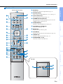 9
9
-
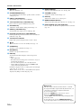 10
10
-
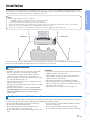 11
11
-
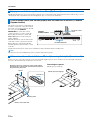 12
12
-
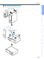 13
13
-
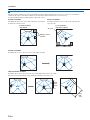 14
14
-
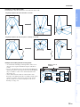 15
15
-
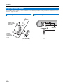 16
16
-
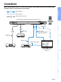 17
17
-
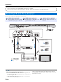 18
18
-
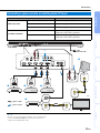 19
19
-
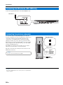 20
20
-
 21
21
-
 22
22
-
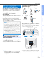 23
23
-
 24
24
-
 25
25
-
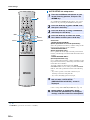 26
26
-
 27
27
-
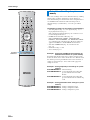 28
28
-
 29
29
-
 30
30
-
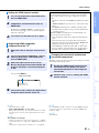 31
31
-
 32
32
-
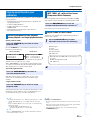 33
33
-
 34
34
-
 35
35
-
 36
36
-
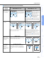 37
37
-
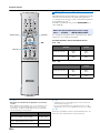 38
38
-
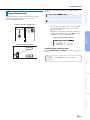 39
39
-
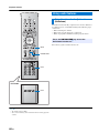 40
40
-
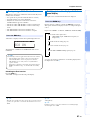 41
41
-
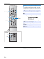 42
42
-
 43
43
-
 44
44
-
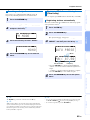 45
45
-
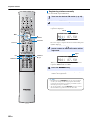 46
46
-
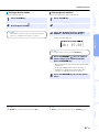 47
47
-
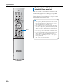 48
48
-
 49
49
-
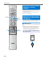 50
50
-
 51
51
-
 52
52
-
 53
53
-
 54
54
-
 55
55
-
 56
56
-
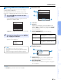 57
57
-
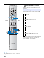 58
58
-
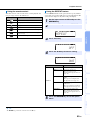 59
59
-
 60
60
-
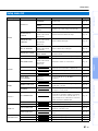 61
61
-
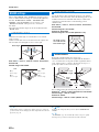 62
62
-
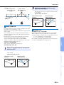 63
63
-
 64
64
-
 65
65
-
 66
66
-
 67
67
-
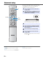 68
68
-
 69
69
-
 70
70
-
 71
71
-
 72
72
-
 73
73
-
 74
74
-
 75
75
-
 76
76
-
 77
77
-
 78
78
-
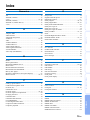 79
79
-
 80
80
-
 81
81
-
 82
82


Yamaha YSP-4300 El manual del propietario
- Tipo
- El manual del propietario
- Este manual también es adecuado para
en otros idiomas
- français: Yamaha YSP-4300 Le manuel du propriétaire
- italiano: Yamaha YSP-4300 Manuale del proprietario
- English: Yamaha YSP-4300 Owner's manual
- Deutsch: Yamaha YSP-4300 Bedienungsanleitung
- русский: Yamaha YSP-4300 Инструкция по применению
- Nederlands: Yamaha YSP-4300 de handleiding
- dansk: Yamaha YSP-4300 Brugervejledning
- svenska: Yamaha YSP-4300 Bruksanvisning
- Türkçe: Yamaha YSP-4300 El kitabı
- suomi: Yamaha YSP-4300 Omistajan opas
Artículos relacionados
-
Yamaha YHT-S401 El manual del propietario
-
Yamaha YSP-2500 El manual del propietario
-
Yamaha YRS-700 El manual del propietario
-
-
-
-
Yamaha SRT-1000 El manual del propietario
-
-
Yamaha YSP-2200 El manual del propietario
-
Yamaha YSP-4000 El manual del propietario