Solución de problemas
GUÍA DE USO Y MANTENIMIENTO
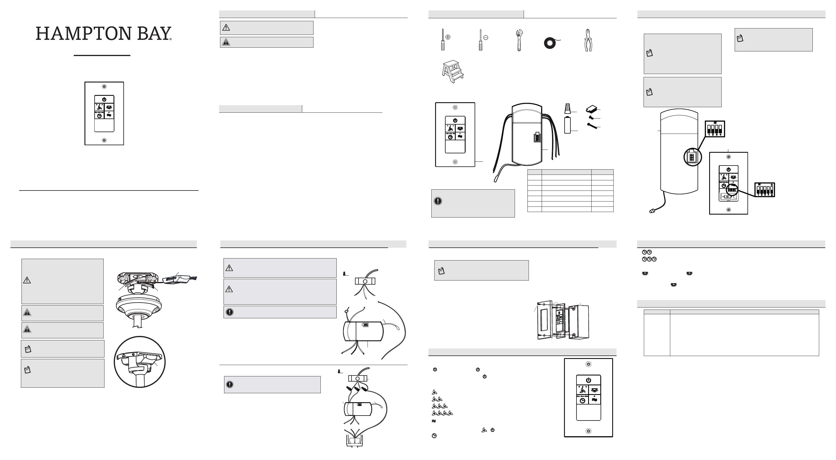
CONTROL REMOTO DE PARED
COMFORT BREEZETM
¿Preguntas, problemas o piezas faltantes? Antes de regresar a la tienda,
llama al servicio al cliente de lunes a viernes entre 8:00 a.m. y 6:00 p.m. (hora estándar del Este),
y los sábados de 9:00 a.m. a 6:00 p.m. (hora estándar del Este)
1-855-HD HAMPTON
HAMPTONBAY.COM
Apreciamos la conanza que has depositado en Hampton Bay al comprar este control de pared. Nos esforzamos
continuamente en crear productos de calidad diseñados para mejorar tu hogar. Visítanos por Internet para ver
nuestra línea completa de productos disponibles para las necesidades de mejoras de tu hogar.
¡Gracias por elegir Hampton Bay!
1. Lee y guarda estas instrucciones.
2. Todo el cableado debe cumplir con el Código
Nacional de Electricidad ANSI/NFPA 70-1999 y con
los códigos locales de electricidad. La instalación
eléctrica debe ser hecha por un electricista
certicado y calicado.
3. El suministro al receptor del control remoto debe
estar conectado a un interruptor principal, por
ejemplo, un interruptor de pared ya existente.
4. Desconecta el suministro de energía del interruptor
de pared antes de trabajar en el receptor del control
remoto o ventilador de techo.
ADVERTENCIA: Para reducir el riesgo de incendio
o lesiones, no utilices este producto con ningún
control de pared variable (reóstato).
Información de seguridad
Garantía
PRECAUCIÓN: Conectar el cableado de manera
incorrecta dañará este receptor.
El proveedor garantiza que el control remoto y el receptor no presentan defectos de fabricación ni de
materiales, al momento en que es enviado desde la fábrica, por un período de un año a partir de la
fecha de adquisición por el comprador original. Acordamos reparar todos los defectos del tipo antes
mencionado sin cargo alguno o, a nuestra discreción, reemplazar el producto por un modelo de igual
calidad o superior si el producto es devuelto. Para obtener servicio de garantía, tiene que presentar una
copia del recibo como comprobante de compra. Todos los costos de retiro y reinstalación del producto
correrán por tu cuenta. No están cubiertos bajo esta garantía los daños a ninguna de las piezas como
resultado de accidentes, instalación o uso incorrectos o por instalación de cualquier accesorio. Cualquier
servicio realizado por personal no autorizado invalidará la garantía. No hay ninguna otra garantía expresa.
Por este medio The Home Depot queda exento de todas y cada una de las garantías, incluyendo pero
sin limitarse a aquellas de comercialización e idoneidad para un n particular, en el alcance permitido
por la ley. La duración de cualquier garantía implícita que no se pueda eximir está limitada al período
especicado en la garantía explícita. Algunos estados no permiten limitar la duración de la garantía;
por consiguiente, la limitación anterior puede no aplicarse a su caso. El minorista no será responsable
por daños directos, indirectos o especiales que resulten o deriven del uso o rendimiento del producto,
excepto en casos en que lo estipule la ley. Algunos estados no permiten excluir ni limitar daños directos
o indirectos, por lo que la limitación o exclusión anterior podría no aplicarse a su caso. Esta garantía
otorga derechos legales especícos y es posible que usted tenga también otros derechos que varían de
un estado a otro. Esta garantía sustituye todas las garantías anteriores. Los costos de envío de cualquier
devolución de productos como parte de una reclamación de garantía corren por cuenta del cliente.
Comuníquese con el equipo de servicio al cliente llamando al 1-855-HD -HAMPTON o visite
www.HAMPTONBAY.COM
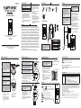
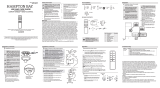
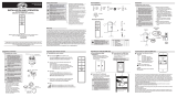
Preinstalación
HERRAMIENTAS NECESARIAS
Destornillador
Phillips
Destornillador
de cabeza
plana
Llave
ajustable
Cinta de
electricista Cortacables
Escalera de tijera
Pieza Descripción Cantidad
A Transmisor 1
B Receptor 1
C Conector plástico para cables 5
D Batería 23A (12 V) 1
E Enchufe de goma de silicona 1
F Tornillo blanco 2
G Tornillo 2
CONTENIDO DEL PAQUETE
IMPORTANTE: Este producto y/o sus
componentes están protegidos por una
o más de las siguientes patentes de
E.E.U.U.: 5,947,436; 5,988,580; 6,010,110;
6,046,416, 6,210,117 y otras
patentes pendientes.
A
B
C
D
E
F
G
Instalación
1
2
NOTA: Las frecuencias del receptor y de la
unidad de mano han sido preconguradas
en la fábrica. Antes de instalar el receptor,
asegúrate de que los interruptores
en línea del receptor y el control de
pared estén congurados en la misma
frecuencia. Los interruptores del control
de pared están ubicados dentro del
compartimento de la batería.
NOTA: La batería se debilitará con el
tiempo y deberá ser reemplazada antes
de que se produzca alguna fuga, ya que
esto dañará la unidad de mano. Desecha
la batería adecuadamente y mantenla
fuera del alcance de los niños.
Cómo congurar los códigos del
control de pared y el receptor
Cómo instalar el receptor
ADVERTENCIA: Para reducir el riesgo de
incendio o de descarga eléctrica, recuerda
desconectar la electricidad. El cableado
eléctrico debe cumplir todos los requisitos
de los códigos eléctricos nacionales y
locales. La fuente de energía y el ventilador
tienen que ser de 110/120 V y 60 Hz. No
utilices este producto con ningún control
de pared variable. Conectar el cableado de
manera incorrecta dañará este receptor.
PRECAUCIÓN: Si otros cables del ventilador
son de color diferente, un electricista
certicado deberá instalar esta unidad.
PRECAUCIÓN: No sumerjas en agua. No
hales ni recortes los cables terminales. No
dejes caer ni golpees la unidad.
A
B
Antena
Instalación (continuación)
Problema Solución
El ventilador
no enciende. □Verica los fusibles y disyuntores principales y secundarios.
□Asegúrate de que el interruptor de pared esté en posición de encendido (ON), si corresponde.
□Verica las conexiones de cables en línea al ventilador y conexiones de cables del
interruptor en la caja de interruptores.
□Revisa la batería del transmisor.
□Asegúrate de estar en el rango normal de 3 a 6 metros.
□Asegúrate de que las conguraciones del interruptor en línea sean las mismas para el
transmisor y el receptor.
□Recuerda desconectar la electricidad antes de vericar las conguraciones de los
interruptores en línea.
Funcionamiento
Artículo núm. 1005 447 797
Modelo núm. 98139
5. Instala el receptor en la cubierta del ventilador
para asegurar protección adecuada.
6. Esta unidad debe usarse solamente para
controlar ventiladores de techo en una fuente
de corriente de CA de 110 V y 60 Hz.
7. Apropiado para la instalación en lugares húmedos.
No sumerjas en agua.
8. Los diagramas eléctricos son sólo para referencia.
9. No hales ni recortes los cables terminales.
10. No dejes caer ni golpees la unidad.
11. Después de concluir las conexiones eléctricas,
asegúralas con cinta de electricista. Debes
voltear los conductores empalmados hacia
arriba y meterlos con cuidado en la caja
eléctrica. Los cables deben desplegarse
separados con el conductor a tierra y el
conductor a tierra del equipo, hacia uno
de los lados de la caja eléctrica.
NOTA: El ventilador de techo debe estar
congurado en velocidad ALTA y el kit de luces
(si lo tiene) en la posición de ENCENDIDO.
NOTA: La batería se debilitará con el tiempo
y deberá ser reemplazada antes de que se
produzca alguna fuga ya que esto dañará
el transmisor. Desecha adecuadamente las
baterías usadas. Mantén el control remoto
fuera del alcance de los niños.
NOTA: Es obligatorio que el código
utilizado tanto para el transmisor como
para el receptor sea exactamente el
mismo, ya que de otra manera, el control
remoto no funcionará.
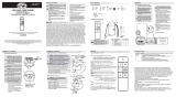
AAA BBB
B
Receptor (B) correctamente
colocado en el soporte
de montaje.
B
Cómo congurar el código del control de pared
□Inserte un destornillador pequeño plano en una de
las ranuras en la parte inferior de la cuberta de la
bateria en la parte frontal del control de pared (A) y
tire suavemente para retirarla.
□Desliza los interruptores de código hacia arriba o
hacia abajo, según tu elección. La conguración de
fábrica es hacia arriba.
□Para los ventiladores con bombillas regulable,
desliza el interruptor O/D a la posición “D”. Si
no utilizas las bombillas regulable, desliza el
interruptor a la posición “O”.
□Coloca 1 batería A23 (12 V) (incluida).
□Coloca de nuevo la cubierta en el control de pared (A).
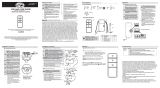
Cómo congurar el código del receptor
□Desliza los interruptores del receptor (B) hacia las
mismas posiciones que elegiste para el control
remoto (A).
□Inserta el enchufe de goma de silicona (E) en el
oricio del receptor (B) para cubrir los interruptores.
□Ubica los cables de suministro doméstico
(AAA) a un lado del soporte de montaje
deslizante (A) y coloca los cables del
ventilador (BBB) en el lado opuesto.
□Inserta el extremo angosto del receptor
(como se muestra: el lado plano hacia
el techo) en el soporte de montaje
deslizante hasta quedar apoyado en la
parte superior del ensamblaje del tubo
bajante/esfera.
Instalación (continuación)
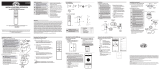
3Cómo conectar los cables del receptor a los cables del hogar
IMPORTANTE: Usa las tuercas de conexión de cables (C) incluidas con
tu ventilador. Sujeta los conectores con cinta de electricista
y asegúrate de que no haya conexiones o cables sueltos.
ADVERTENCIA: Cada cable no suministrado con este ventilador
está diseñado para aceptar un máximo de un solo circuito
eléctrico doméstico de calibre 12 y dos cables del ventilador.
Si tienes un cableado doméstico superior a calibre 12 o
más de un cable doméstico para conectar al cableado del
ventilador, consulta a un electricista para precisar el tamaño
adecuado de las tuercas para cables a usar.
□Separa los cables de manera que los cables verde y blanco queden
de un lado de la caja eléctrica y el cable negro quede del otro lado.
□Conecta los cables verdes del ventilador al cable de conexión a
tierra de la casa (este puede ser verde o pelado) con una tuerca de
conexión de cables (C).
□Conecta el cable negro (o rojo) del receptor al cable negro del hogar
(positivo), usando una tuerca de conexión de cables (C).
□Conecta el cable blanco del receptor al cable blanco del hogar
(neutro), usando una tuerca de conexión de cables (AA).
□Asegura cada tuerca de conexión de cables con cinta de electricista.
Negro
(o rojo)
Negro
Verde
(o pelado)
Verde
Caja
eléctrica
en el techo
(MM)
Antena
Blanco
B
C (x3)
ADVERTENCIA: Para evitar una posible descarga eléctrica,
desconecta la electricidad de la caja de fusibles principal
antes de realizar el cableado. Si crees que no tienes
suciente conocimiento o experiencia sobre cableado
eléctrico, contacta a un electricista certicado.
Cómo conectar los cables del ventilador al receptor
□Conecta el cable blanco del motor del ventilador al cable blanco
del receptor usando una tuerca de conexión de cables (C).
□Conecta el cable negro del motor del ventilador al cable negro
del receptor usando una tuerca de conexión de cables (C).
□Conecta el cable azul del motor del ventilador al cable azul del
receptor usando una tuerca de conexión de cables (C).
□Asegura cada tuerca de conexión de cables con cinta
de electricista.
□Gira la tuerca de conexión de cables (C) hacia arriba
y coloca el cableado dentro de la caja eléctrica (MM).
4
IMPORTANTE: Usa las tuercas de conexión de
cables (C) incluidas con tu ventilador. Sujeta los
conectores con cinta de electricista y asegúrate de
que no haya conexiones o cables sueltos.
en el techo
(MM)
B
Azul
Antena
NegroBlanco
Verde
C (x3)
- Oprime y suelta el botón para encender o apagar el ventilador y las luces.
□Mantén presionado el botón durante 3 segundos para usar el “temporizador
inmediato”; esto encenderá las luces durante 30 segundos (si usas bombillas
regulables, las luces se encenderán al 50% de su brillo).
- Oprime y suelta 1 vez - para encender el ventilador a velocidad alta.
- Oprime y suelta 2 veces - para encender el ventilador a velocidad media.
- Oprime y suelta 3 veces - para encender el ventilador a velocidad baja.
- Oprime y suelta 4 veces - para apagar el ventilador.
- Mantén presionado este botón durante 3 segundos para activar el modo Comfort
BreezeTM. Este cambiará la velocidad del ventilador al azar, simulando una brisa relajante.
Para cancelar esta función, oprime o .
- Con el ventilador encendido, oprime 1 vez - para activar el temporizador con 2 horas
de funcionamiento.
1Cómo operar el control remoto
Este equipo ha sido probado y se determinó que cumple con los límites establecidos para un dispositivo digital Clase B, de acuerdo con la Parte
15 de las Normas de la FCC. Estos límites fueron establecidos para ofrecer protección razonable contra la interferencia dañina durante uso
residencial. Este equipo genera, usa y puede irradiar energía de radiofrecuencia y, si no se instala y usa de acuerdo con las instrucciones, puede
causar interferencia dañina a comunicaciones radiales. Sin embargo, no hay garantía de que no ocurrirá interferencia en una instalación particular.
Si este equipo causa interferencia que perjudica la recepción de radio o televisión, lo cual puede determinarse encendiendo y apagando el equipo,
se recomienda al usuario que trate de corregir la interferencia con una o más de las siguientes medidas:
– reorientar o reubicar la antena receptora.
– incrementar la distancia entre los equipos y el receptor.
– conectar el equipo a un tomacorriente en un circuito distinto al que el receptor está conectado.
– consultar al distribuidor o algún técnico de radio/TV con experiencia.
PRECAUCIÓN:
Los cambios o modicaciones sin aprobación expresa del responsable de este dispositivo podrían anular el derecho del usuario a operar el equipo.
ID de FCC: KUJCE10321
Este dispositivo cumple con la Parte 15 de las Normas de la FCC. Su operación está sujeta a las dos condiciones siguientes: (1) este dispositivo
no debe causar interferencia dañina, y (2) este dispositivo tiene que aceptar cualquier interferencia recibida, incluyendo aquella que pueda afectar
su funcionamiento.
Funcionamiento (continuación)
- Con el ventilador encendido, oprime 2 veces - para activar el temporizador con 4 horas de funcionamiento.
- Con el ventilador encendido, oprime 3 veces - para activar el temporizador con 8 horas de funcionamiento.
- Oprime y suelta el botón para encender o apagar las luces.
Si utilizas bombillas regulables y previamente conguraste el interruptor O/D del control remoto en la posición “D”, mantén
presionado el botón para activar la función de regulación de intensidad.
Instalación (continuación)
5Cómo instalar el control remoto de pared
existente
F
G
□Con el cortacircuitos apagado, quita la placa decorativa
del interruptor de pared y el interruptor de la caja
eléctrica.
□Desconecta el cableado doméstico del
interruptor existente.
□Enrosca los cables a tierra (verdes o pelados) y
asegúralos con un conector de cables plástico.
□Enrosca los cables blancos y asegúralos con un conector
de cables plástico.
□Enrosca los cables negros y asegúralos con un conector
de cables plástico.
□Asegura cada conector de cables con cinta de
electricista e inserta cada conjunto de cables dentro
de la caja eléctrica.
□Coloca el control remoto de pared sobre la
caja eléctrica y asegúralo con los tornillos (G).
□Coloca la placa decorativa del interruptor
de pared sobre el control remoto de pared y
ajústala con los tornillos blancos (F).
□Restablece la electricidad del cortacircuitos.
NOTA: Al conectar los cables, es posible que sea
necesario pelarlos para realizar una conexión
segura. Si tienes preguntas, consulta con un
electricista calicado.
Modelo del controlador: TR223A


 1
1
 2
2


 Hampton Bay 68109 Guía de instalación
Hampton Bay THERMOSTATIC REMOTE CONTROL Guía de instalación
 Hampton Bay 98131 Guía de instalación
 Hampton Bay 68131 Guía de instalación
 Hampton Bay 68108 Guía de instalación
 Hampton Bay 99432 Guía de instalación
 Hampton Bay 99432 Guía del usuario
 Hampton Bay 68130 Guía de instalación


