La página se está cargando...

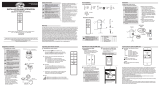
Control the Fan with the WINK App
INSTALLATION AND OPERATION
CEILING FAN REMOTE CONTROL
Safety Information
Warranty
CAUTION: Incorrect wire connections will
damage this receiver.
The supplier warrants the remote control and receiver to be free from defects in workmanship and material present at
time of shipment from the factory for a period of one year after the date of purchase by the original purchaser. We agree
to correct such defects without charge or at our option replace with a comparable or superior model if the product is
returned. To obtain warranty service, you must present a copy of the receipt as proof of purchase. All costs of removing
and reinstalling the product are your responsibility. Damage to any part such as by accident or misuse or improper
installation or by afxing any accessories, is not covered by this warranty. Servicing performed by unauthorized
persons shall render the warranty invalid. There is no other express warranty. Home Depot hereby disclaims any and
all warranties, including but not limited to those of merchantability and tness for a particular purpose to the extent
permitted by law. The duration of any implied warranty which cannot be disclaimed is limited to the time period as
specied in the express warranty. Some states do not allow a limitation on how long an implied warranty lasts, so the
above limitation may not apply to you. The retailer shall not be liable for incidental, consequential, or special damages
arising out of or in connection with product use or performance except as may otherwise be accorded by law. Some
states do not allow the exclusion of incidental or consequential damages, so the above exclusion or limitation may
not apply to you. This warranty gives specic legal rights, and you may also have other rights which vary from state to
state. This warranty supersedes all prior warranties. Shipping costs for any return of product as part of a claim on the
warranty must be paid by the customer.
Contact the Customer Service Team at 1-855-HD HAMPTON or visit www.HAMPTONBAY.COM
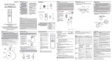
Pre-Installation
TOOLS REQUIRED
Phillips
screw-
driver
Flathead
screw-
driver
Adjustable
wrench
Electrical
tape
Wire
cutter
Step ladder
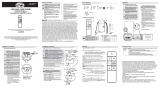
Part Description Quantity
A Remote control 1
B Receiver 1
C AAA 1.5V battery 2
D Plastic wire connector 5
E White painting screw 1
F Rubber isolated pad 2
PACKAGE CONTENTS
IMPORTANT: This product and/or
components are governed by one or more
of the following U.S. Patents: 5,947,436;
5,988,580; 6,010,110; 6,046,416, 6,210,117
and other patents pending.
Installation
1
NOTE: The frequencies on your receiver
and hand unit have been preset at the
factory. Before installing the receiver, make
sure the dip switches on the receiver and
hand unit are set to the same frequency.
The dip switches on the hand unit are
located inside the battery compartment.
NOTE: The battery will weaken with age
and should be replaced before leaking
takes place as this will damage the hand
unit. Dispose of the used battery properly,
keep the battery out of the reach of
children.
Setting the codes on the
remote control and receiver
Operating Fan with the WINK App
1. YOU MUST SET CEILING FAN TO HIGH SPEED
AND LIGHT KIT (IF ANY) TO ON POSITION BEFORE
OPERATING REMOTE CONTROL.
2. The supply to the remote control receiver should
be connected through a mains switch, i.e. existing
wall switch.
3. Disconnect from power supply at wall switch before
working on remote control receiver or ceiling fan.
4. Install receiver into the ceiling fan canopy of the fan
to ensure proper protection.
5. This unit is to be used for the control of ceiling fan
and in a AC110/120V 60Hz power supply only.
6. Do not install in damp locations or immerse in
water. (For indoor use only.)
7. Do not pull on or cut leads shorter.
8. Do not drop or bump the unit.
9. Do not mix old and new batteries.
10. Do not mix alkaline, standard (carbon-zinc), or
rechargeable (ni-cad, ni-mh, etc.) batteries.
NOTE: It is imperative that the code used
for both transmitter and receiver is exactly
the same, otherwise remote controller will
not work.
Setting the Code on the Remote
□ Remove the battery cover on the back of
the remote control by pressing rmly on the
arrow and sliding the cover off.
□ Slide the code switches to your choice of
either up or down. The factory setting is up.
□ For fans with dimmable bulbs, slide the
“Light Function” switch (O/D) to the position
marked “D”. If you are using non dimmable
bulbs slide the “Light Function” switch to the
“O” position.
□ Install two 1.5V AAA batteries (included).
□ Replace the battery cover on the remote
control.
Setting the Code on the Receiver
□ Slide the code switches on the receiver to
the same positions as set on the remote
control.
Operating Your Remote Control
1
Operating the remote control
This equipment has been tested and found to comply with the limits for a Class B digital device, pursuant to Part 15 of the FCC Rules. These
limits are designed to provide reasonable protection against harmful interference in a residential installation. This equipment generates, uses
and can radiate radio frequency energy and, if not installed and used in accordance with the instructions, may cause harmful interference to
radio communications. However, there is no guarantee that interference will not occur in a particular installation. If this equipment does cause
harmful interference to radio or television reception, which can be determined by turning the equipment off and on, the user is encouraged to
try to correct the interference by one or more of the following measures:
--Reorient or relocate the receiving antenna.
--Increase the separation between the equipment and receiver.
--Connect the equipment into an outlet on a circuit different from that to which the receiver is connected.
--Consult the dealer or an experienced radio/TV technician for help.
CAUTION:
Any changes or modications not expressly approved by the grantee of this device could void the user’s authority to operate the equipment.
FCC ID: KUJCE10406, KUJCE10407
This device complies with Part 15 of the FCC Rules. Operation is subject to the following two conditions: (1) This device may not cause harmful
interference, and (2) this device must accept any interference received, including interference that may cause undesired operation.
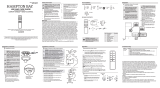
1 2 3
ON
4
1 2 3 4
ON
D O
Remote
Control
Receiver
Dip Switch
FCC ID: KUJCE10319
IC ID:10786A-TR221A
MADE IN CHINA
MODELO: TR221A
FCC ID: KUJCE10319
IC ID: 10786A-TR221A
HECHO EN CHINA
MODèLE: TR221A
FCC ID: KUJCE10319
IC ID: 10786A-TR221A
FABRIQUé EN CHINE
1 2 3 4
ON
DIP
Light Function
Switch
Press and release the button to turn the light on or off.
1
Downloading the WINK
Application
□ Using your smart device, navigate to the
application store (Apple App Store or Google
Play). Download the free WINK app and
create an account.
2
Connecting to the WINK Hub
□ Ensure your WINK Hub is connected to WiFi
by conrming the indicator light is a solid
blue color.
□ With the app open, select “add a product.”
□ Choose the WINK Hub and follow the
instructions on the app to add your fan.
Be sure your Hub is plugged in and
within range of your fan.
3:17 PMWi-Fi
53%
Cancel
Help
CEILING FAN
NEXT
3
Pairing the Fan to the WINK Hub
□ When instructed, turn on your fan. Once pairing is successful,
the fan will turn on at low speed and the light will blink 5 times.
Operating Your Remote Control
4
Fan Speed
• OFF - Turns fan off
• 1- Turns the fan to Low speed.
• 2- Turns the fan to Medium speed.
• 3- Turns the fan to Medium 2 speed.
• 4- Turns the fan to High speed.
• BREEZE- Randomly alternates fan speeds to
create an organic breeze effect.
Fan Light
• OFF/ON - Turns fan light off or on.
Select and slide to dim or brighten light.
Questions, problems, missing parts? Before returning to the store, call Customer Service
8 a.m. - 6 p.m., EST, Monday-Friday, 9 a.m. - 6 p.m., EST Saturday
1-855-HD HAMPTON
HAMPTONBAY.COM
We appreciate the trust and condence you have placed in Hampton Bay through the purchase of this remote control.
We strive to continually create quality products designed to enhance your home. Visit us online to see our full line of
products available for your home improvement needs.
Thank you for choosing Hampton Bay!
Item #722-493
Model #99432
-Press and release the button to turn the fan on or off.
Press and hold the button for 3 seconds to use the “walk away
time delay”; this will activate the light for 30 seconds (if you are using
dimmable bulbs the light will be activated at 50% brightness.
- Fan Speed - LED’s on the fan speed button will illuminate to the
corresponding speed.
- Press button once - turns the fan on high speed.
- Press button twice - turns the fan on medium-high speed.
- Press button three times - turns the fan on medium-low speed.
- Press button four times - turns the fan on low speed.
Press button ve times - fan will turn off.
- Comfort Breeze
TM
- Press and release the button to enable Comfort
Breeze
TM
; this will change your fan speed randomly, simulating a
relaxing breeze. To cancel this feature press or .
- Timer
- While the fan is on press button once - turns on a 2 hour run timer.
- While the fan is on press button twice - turns on a 4 hour run timer.
- While the fan is on press button three times - turns on a 8 hour run timer.
- Light ON/OFF
If you are using dimmable bulbs and you have previously set the dip
switch in your remote control to the “D” position, press and hold the
button to activate the dimmer function.
CAUTION: To reduce the risk of re or injury, do
not use this product in conjunction with any
variable (rheostat) wall control.
NOTE: The battery will weaken with age and
should be replaced before leaking takes place
as this will damage the hand unit. Dispose of the
used battery properly, keep the battery out of the
reach of children.
WARNING: To avoid possible electrical shock,
turn the electricity off at the main fuse box
before wiring. If you feel you do not have
enough electrical wiring experience, contact a
licensed electrician.
NOTE: Be sure your WINK Hub is plugged
in and within range of your fan. Refer to
Wink HUB user manual for the range.
NOTE: If using a dimmer with these lights, set dimmer at
highest setting for best results.
NOTE: Reset your fan if the pairing is taking longer than
expected. Turn off your fan for 3 seconds, then turn it back
on for 3 seconds. Repeat these steps 5 times. The light will
blink 3 times when factory reset is successful. If the pairing
failed, please reset the device to original setting and re-start
the pairing.
O 1 2 3 4 Breeze
O On
FAN SPEED
FAN LIGHT
FANS
3:19 PMWi-Fi
53%
Fan Light Settings
• During set up, the customer is asked if the fan
has a light kit.
• If your fan has a light, select “Fan Light On.”
• If your fan does not have a light, select “Fan
Light Off.”
• Press SAVE to conrm.
Ceiling Fan
Version
Location
Set Timer
>
>
Controller
Settings
Fan Light Settings
>
Users
Owner
Add a user
Software Version
REMOVE THIS FAN
+
Hub
.
Model
Name
Master Bedroom
Statu s
Connected
✓
Timer
When on “fan control screen,” press settings
button in upper right corner to display the
settings panel.
• Select fan to display control panel.
• Scroll down the control panel and select “Set
Timer.”
• Scroll through the hours and minute columns
to select the duration of the timer.
• Press OK to start the timer.
Set Timer
Cancel
Ok
hours
min
3
15
CEILING FAN
Connect to Wink
3:19 PM
Wi-Fi
53%
Help
Cancel
SUCCESS!
NEXT
Wink do es not manufacture this pr oduct you have connected. By proceedi ng,
you acknowledg e and accept that Wink does not gua rantee the pe rformance of
this prod uct you have connected to Wink.
D
C
1 2 3 4
ON
DIP
B
A
F
E
3
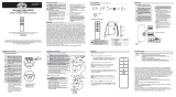
Installing the receiver
WARNING: To reduce the risk of re or electric
shock, remember to disconnect power. The
electrical wiring must meet all local and
national electrical code requirements. The
electrical source and fan must be 110/120 volt,
60Hz. Do not use this product in conjunction
with any variable wall control. Incorrect wire
connection can damage this receiver.
CAUTION: If fan or house wires are a different
color, have this unit installed by a licensed
electrician.
CAUTION: Do not install in a damp location or
immerse in water (For indoor use only). Do
not pull on or cut leads shorter. Do not drop or
bump the unit.
Installation (continued)
NOTE: The ceiling fan must be set at HIGH
speed and light kit (if installed) should be set to
the ON position.
NOTE: For better performance with the WINK
system, the T-Shaped antenna stick should
be mounted to the ceiling outside of the fan’s
ceiling canopy using the pre-mounted double-
stick tape and wood screw (included).
□ Position the house supply wires (AAA) to one side
of the slide-on mounting bracket; position the fan
wires (BBB) to the opposite side.
□ Insert the narrow end of the receiver (as shown, at
side towards the ceiling) into the slide-on mounting
bracket until it rests on top of the ball/downrod
assembly. The canopy comes up to cover the
receiver and bracket.
VIEW AFTER
INSTALLATION
CEILING
WINK antenna
mount to ceiling using wood screw
WINK
antenna
Receiver antenna
AAA
BBB
WINK antenna
Receiver antenna
(Leave connected and do not cut)
2
Installing the rubber isolated pads
□ Loosen the two screws provided with the outlet
box; insert two rubber isolated pads (F) between
the mounting bracket and the outlet box; rmly
tightened the two screws.
F
Outlet box
Mounting
Bracket
Installation (continued)
4
Wiring the receiver to the household wiring
IMPORTANT: Use the wire connecting nuts (AA) supplied with
your fan. Secure the connectors with electrical tape and
ensure there are no loose strands or connections.
WARNING: Each wire not supplied with this fan is designed to
accept up to one 12-gauge house wire and two wires from the
fan. If you have larger than 12-gauge house wiring or more
than one house wire to connect to the fan wiring, consult an
electrician for the proper size wire nuts to use.
□ Spread the wires apart so that the green and white wires are on one
side of the outlet box and the black wire is on the other side.
□ Connect the green fan wires to the household ground wire (this may
be a green or bare wire) using a wire connecting nut (AA).
□ Connect the receiver black (or red) wire to the household black (hot)
wire using a wire connecting nut (AA).
□ Connect the receiver white wire to the household white wire (neutral)
wire using a wire connecting nut (AA).
□ Secure each wire connecting nut using electrical tape.
Black
(or Red)
Black
Green
(or Bare)
Green
Outlet Box
in the ceiling
(MM)
Antenna
White
B
C (x3)
WARNING: To avoid possible electrical shock, turn the
electricity off at the main fuse box before wiring. If you
feel you do not have enough electrical wiring knowledge or
experience, contact a licensed electrician.
Wiring the fan to the receiver
□ Connect the fan motor white wire to the receiver white wire
using a wire connecting nut (AA).
□ Connect the fan motor black wire to the receiver black wire
using a wire connecting nut (AA).
□ Connect the fan motor blue wire to the receiver blue wire
using a wire connecting nut (AA).
□ Secure each wire connecting nut using electrical tape.
□ Turn the wire connecting nut (AA) upward and push the wiring
into the outlet box (MM).
5
IMPORTANT: Use the wire connecting nuts (AA)
supplied with your fan. Secure the connectors
with electrical tape and ensure there are no loose
strands or connections.
Outlet box
in the ceiling
(MM)
B
Blue
Antenna
Black
White
Green
C (x3)

Si utilizas bombillas regulables y previamente conguraste el interruptor
DIP del control remoto en la posición “D”, oprime y mantén presionado el
botón para activar la función de regulación de intensidad.
- Oprime y suelta el botón para encender o apagar el ventilador.
Controla el ventilador con la aplicación WINK
INSTALACIÓN Y FUNCIONAMIENTO
CONTROL REMOTO PARA VENTILADOR DE TECHO
Información de seguridad
Garantía
PRECAUCIÓN: Conectar incorrectamente el cableado
dañará este receptor.
El proveedor garantiza, por un período de un año a partir de la fecha de adquisición por el comprador original, que
el control remoto y el receptor no presentan defectos de fabricación ni de materiales al momento del envío desde la
fábrica. Acordamos reparar todos tales defectos sin cargo alguno o, a nuestra discreción, reemplazar por un modelo de
igual calidad o superior si el producto es devuelto. Para obtener servicio de garantía tiene que presentarse una copia
del recibo como comprobante de compra. Todos los costos de retiro y reinstalación del producto correrán por tu cuenta.
No están cubiertos bajo esta garantía los daños causados a ninguna de las piezas por accidente, uso indebido o mala
instalación, ni por instalación de cualquier accesorio. Cualquier servicio realizado por personal no autorizado invalidará
la garantía. No hay ninguna otra garantía expresa. Por este medio The Home Depot queda exento de todas y cada una
de las garantías, incluyendo, pero sin limitarse a, aquellas de comercialización e idoneidad para un n particular en
el alcance permitido por la ley. La duración de cualquier garantía implícita sin posibilidad de exención está limitada al
período especicado en la garantía explícita. Algunos estados no permiten limitar la duración de la garantía, así que la
limitación anterior pudiera no aplicarse a su caso. El minorista no será responsable por daños directos, indirectos ni
especiales que resulten o deriven del uso o funcionamiento del producto, excepto en los casos estipulados por la ley.
Algunos estados no permiten excluir ni limitar daños directos o indirectos, así que la limitación o exclusión anterior
pudiera no aplicarse a su caso. Esta garantía otorga derechos legales especícos y es posible que usted tenga también
otros derechos, que varían de un estado a otro. Esta garantía sustituye todas las garantías anteriores. Los costos de
envío de cualquier devolución de productos como parte de una reclamación de garantía corren por cuenta del cliente.
Comuníquese con el equipo de servicio al cliente llamando al 1-855-HD -HAMPTON o visite www.HAMPTONBAY.COM
Preinstalación
HERRAMIENTAS NECESARIAS
Destornillador
Phillips
Destornillador
de cabeza
plana
Llave
ajustable
Cinta de
electricista
Cortacables
Escalera de tijera
Pieza Descripción Cantidad
A Control remoto 1
B Receptor 1
C Batería AAA de 1.5 V 2
D Conector plástico para cables 5
E Tornillo blanco 1
F Almohadillas de goma aislado 2
CONTENIDO DEL PAQUETE
IMPORTANTE:Este producto y/o sus componentes
están protegidos por una o más de las siguientes
patentes de los EE. UU.: 5,947,436; 5,988,580;
6,010,110; 6,046,416, 6,210,117, así como por
otras patentes pendientes.
Instalación
1
NOTA: Las frecuencias del receptor y de la
unidad de mano están preconguradas de
fábrica. Antes de instalar el receptor, asegura
que los interruptores en línea del receptor y de
la unidad de mano estén congurados en la
misma frecuencia. Los interruptores en línea de
la unidad de mano están ubicados dentro del
compartimiento de la batería.
NOTA: La batería se debilitará con el tiempo y
deberá ser reemplazada antes de producirse
alguna fuga, ya que esto dañará la unidad de
mano. Mantén la batería fuera del alcance
de los niños y desecha adecuadamente la
batería usada.
Cómo congurar los códigos
del control remoto y el receptor
Como usar el ventilador con la aplicación WINK
1. DEBES CONFIGURAR EL INTERRUPTOR DEL VENTILADOR
DE TECHO EN VELOCIDAD ALTA Y EL KIT DE LUCES (SI LO
TIENE) EN LA POSICIÓN DE ENCENDIDO (“ON”) ANTES
DE PONER EN FUNCIONAMIENTO EL CONTROL REMOTO.
2. El suministro al receptor del control remoto debe estar
conectado a un interruptor principal, por ejemplo, un
interruptor de pared ya existente.
3. Desconecta el suministro de energía del interruptor
de pared antes de trabajar en el receptor del control
remoto o ventilador de techo.
4. Instala el receptor en la cubierta del ventilador para
asegurar protección adecuada.
5. Esta unidad debe usarse sólo para controlar
ventiladores de techo con fuente de corriente de
110/220 V de CA y 60 Hz.
6. No instalar en lugares húmedos ni sumergir en agua.
(Sólo para uso en interiores).
7. No hales ni recortes los cables terminales.
8. No dejes caer ni golpees la unidad.
9. No mezcle las baterias viejas con las nuevas.
10. No mezcle las baterias alkaline, estándar (carbon-zinc) , o
recargable (ni-cad, ni-mh, etc).
NOTA: Es obligatorio que el código utilizado
tanto para el transmisor como para el receptor
sea exactamente el mismo; de otra manera
no funcionará.
Cómo congurar el código del control
remoto
□ Quita la cubierta de la batería en la parte posterior
del control remoto presionando con rmeza sobre
la echa y deslizando la cubierta hasta que salga.
□ Desliza los interruptores de código hacia arriba
o abajo, según tu elección. La conguración de
fábrica es hacia arriba.
□ Para los ventiladores con bombillas de intensidad
regulable, desliza el interruptor de función de luz
(O/D) a la posición “D”. Si no utilizas las bombillas
de intensidad regulable, desliza el interruptor de
función de luz a la posición “O”.
□ Instala dos baterías AAA de 1.5 V (incluidas).
□ Coloca de nuevo la cubierta en el control remoto.
Cómo congurar el código del receptor
□ Desliza los interruptores de código del receptor
hacia las mismas posiciones que elegiste para el
control remoto.
Cómo usar tu control remoto
1
Cómo usar el control remoto
Este equipo ha sido comprobado y se determinó que cumple con los límites establecidos para un dispositivo digital Clase B, de acuerdo
con la Parte 15 de las Normas de la FCC. Estos límites fueron establecidos para ofrecer protección razonable contra la interferencia dañina
durante uso residencial. Este equipo genera, usa y puede irradiar energía de radiofrecuencia; si no se instala y usa de acuerdo con las
instrucciones, puede causar interferencia dañina a comunicaciones radiales. Sin embargo, no hay garantía de que no ocurrirá interferencia
en una instalación particular. Si este equipo causa interferencia que perjudica la recepción de radio o televisión, lo cual puede determinarse
encendiendo y apagando el equipo, se recomienda al usuario que trate de corregir la interferencia con una o más de las siguientes medidas:
– Reorientar o reubicar la antena receptora.
– Incrementar la distancia entre los equipos y el receptor.
– Conectar el equipo a un tomacorriente en un circuito distinto al que el receptor está conectado.
– Consultar al distribuidor o algún técnico de radio/TV con experiencia.
PRECAUCIÓN:
Los cambios o modicaciones sin aprobación expresa del responsable de este dispositivo podrían anular el derecho del usuario a operar el
equipo.
ID de FCC: KUJCE10406, KUJCE10407
Este dispositivo cumple con la Parte 15 de las Normas de FCC. Su operación está sujeta a las dos condiciones siguientes: (1) Este dispositivo
no debe causar interferencia dañina, y (2) tiene que aceptar cualquier interferencia recibida, incluyendo aquella que pudiera afectar su
funcionamiento.
1 2 3
ON
4
1 2 3 4
ON
D O
Control
Remoto
Receptor
Interruptor
DIP
FCC ID: KUJCE10319
IC ID:10786A-TR221A
MADE IN CHINA
MODELO: TR221A
FCC ID: KUJCE10319
IC ID: 10786A-TR221A
HECHO EN CHINA
MODèLE: TR221A
FCC ID: KUJCE10319
IC ID: 10786A-TR221A
FABRIQUé EN CHINE
1 2 3 4
ON
DIP
Interruptor de
función de luz
Oprime y suelta el botón para encender o apagar la luz.
1
Cómo descargar la aplicación
WINK
□ Con tu dispositivo inteligente, explora la tienda
de la aplicación (Apple App Store o Google Play).
Descarga la aplicación WINK gratis y crea una
cuenta.
2
Cómo conectarse al hub WINK
□ Asegura que tu hub WINK tenga conexión WiFi
vericando que la luz indicadora sea azul y constante.
□ Con la aplicación abierta, selecciona
“agregar un producto”.
□ Selecciona el hub WINK y sigue las instrucciones
de la aplicación.
Asegurate de que tu Hub esta
enchufado y ubicado dentro del
alcance previsto con respecto al
ventilador
3:17 PMWi-Fi
53%
Cancela
Ayuda
VENTILADOR DE TECHO
SIGUIENTE
3
Cómo conectarse a la red
□ Enciende el ventilador cuando se indique. Una vez que se
haya realizado el emparejamiento, el ventilador encenderá a
velocidad baja y la luz parpadeará 5 veces.
Cómo usar tu control remoto
4
Velocidad del ventilador
1- Establece la conguración de Velocida
2- Baja del ventilador.
3- Establece la conguración de Velocidad
Media del ventilador.
4- Establece la conguración de Velocidad
Media 2 del ventilador.
5- Establece la conguración de Velocidad Alta
del ventilador.
Luz del ventilador
• APAGADO/ENCENDIDO (ON/OFF) - Apaga o
enciende las luces del ventilador.
¿Preguntas, problemas o piezas faltantes? Antes de devolver a la tienda, llama al Servicio al Cliente
de lunes a viernes, entre 8:00 a.m. y 6:00 p.m. (Hora Estándar del Este),
y los sábados de 9:00 a.m. a 6:00 p.m. (Hora Estándar del Este).
1-855-HD HAMPTON
HAMPTONBAY.COM
Apreciamos la conanza que has depositado en Hampton Bay al comprar este control remoto. Nos esforzamos
continuamente en crear productos de calidad diseñados para mejorar tu hogar. Visítanos por Internet para ver
nuestra línea completa de productos disponibles con vistas a las necesidades de mejoras de tu hogar.
¡Gracias por elegir Hampton Bay!
Artículo núm. 722-493
Modelo núm. 99432
Mantén presionado el botón durante 3 segundos para usar el “tem-
porizador inmediato”; este encenderá las luces durante 30 segundos (si
usas bombillas regulables, las luces se encenderán al 50% de su brillo).
- Velocidad del ventilador: Las luces LED en el botón de velocidad del ventilador
indicarán la velocidad correspondiente.
- Oprime el botón una vez - enciende el ventilador a velocidad alta.
- Oprime el botón dos veces - enciende el ventilador a velocidad media-alta.
- Oprime el botón tres veces - enciende el ventilador a velocidad media-baja.
- Oprime el botón cuatro veces - enciende el ventilador a velocidad baja.
Oprime el botón cinco veces - el ventilador se apaga.
- Comfort Breeze
TM
- Oprime y suelta el botón para activar la función Comfort
Breeze
TM
; esto hará que la velocidad del ventilador cambie al azar, imitando una
brisa relajante. Para cancelar esta función, oprime o .
- Temporizador
- Con el ventilador encendido, oprime el botón una vez - activa el temporizador con 2 horas de funcionamiento.
- Con el ventilador encendido, oprime el botón dos veces - activa el temporizador con 4 horas de funcionamiento.
- Con el ventilador encendido, oprime el botón tres veces - activa el temporizador con 8 horas de funcionamiento.
- Luz ENCENDIDA/APAGADA (ON/OFF)
PRECAUCIÓN: Para reducir el riesgo de incendio o
lesiones, no utilices este producto con ningún control
de pared variable (reóstato).
NOTA: La batería se debilitará con el tiempo y deberá
ser reemplazada antes de producirse alguna fuga,
ya que esto dañará la unidad de mano. Mantén la
batería fuera del alcance de los niños y desecha
adecuadamente la batería usada.
ADVERTENCIA: Para evitar una posible descarga
eléctrica, corta la electricidad en la caja principal de
fusibles antes del cableado. Si crees que no tienes
suciente conocimiento o experiencia sobre cableado
eléctrico, contacta a un electricista certicado.
NOTA: Asegúrate de que tu hub WINK esté enchufado
y en el campo de cobertura de tu ventilador. Consulta
el manual del usuario de WINK HUB para conocer el
alcance.
NOTA: Si usas un regulador de intensidad con estas luces,
colócalo en la conguración más alta para mejores resultados.
NOTA: Reinicia tu ventilador si el emparejamiento se demora más
de lo esperado. Apaga tu ventilador durante 3 segundos y enseguida
enciéndelo durante 3 segundos. Repite estos pasos 5 veces. La luz
parpadeará 3 veces cuando el reinicio de fábrica sea exitoso. Si el
emparejamiento no se realizó, reinicia el dispositivo para establecer
la conguración original y vuelve a comenzar el emparejamiento.
Apagado 1 2 3 4 Brisa
Apagado Encendido
VELOCIDAD DEL VENTILADOR
LUZ DEL VENTILADOR
VENTILADOR
3:19 PMWi-Fi
53%
3:19 PMWi-Fi
53%
TRIUNFO!
La luz de tu ventilador ya está
SIGUIENTE
Wink no f abrica el producto que has conectado. Al continuar, reco noces y
aceptas que W ink no garantiza el funcionamiento de este producto qu e has
conect ado a Wink.
Cancela
Ayuda
VENTILADOR DE TECHO
Conecta a Wink
Ventilador de Techo
Version
Localización
Poner Temporizador
>
>
Controlador
Ajustes
Dirección del Ventilador
>
Usuarios
Propietario
Agregar un usuario
Versión del Software
RETIRA ESTE VENTILADOR
+
Hub
.
Modelo
Nombre
Dormitorio Principal
Estado
Con ectado
✓
temporizador
Cancela
Ok
hours
min
3
15
BRISA (BREEZE) - Alterna al azar la velocidad
del ventilador para surtir efecto de brisa natural.
OFF - Apaga el ventilador
Selecciona y desliza para regular o
aumentar la intensidad de la luz.
Conguraciones de la luz del ventilador
• Durante la conguración, se pregunta al usuario si el ventilador
tiene un kit de luces.
• Si tu ventilador tiene luz, selecciona “Luz del ventilador encendida.”
• Si tu ventilador no tiene luz, selecciona “Luz del ventilador
apagada.”
• Oprime SAVE (GUARDAR) para conrmar.
Temporizador
Cuando estés en la “pantalla de control de ventilador”, oprime el
botón de conguraciones en la esquina superior derecha para
mostrar el panel correspondiente.
• Selecciona ventilador para desplegar el panel de control.
• Desplaza el cursor hacia abajo en el panel de control y
selecciona “Congurar el temporizador.”
• Desplaza el cursor a través de las columnas de horas y minu-
tos para seleccionar la duración del temporizador.
• Oprime OK para iniciar el temporizador.
D
C
1 2 3 4
ON
DIP
B
A
F
E
3
Cómo instalar el receptor
ADVERTENCIA: Para reducir el riesgo de incendio
o de descarga eléctrica, recuerda desconectar la
electricidad. El cableado eléctrico tiene que cumplir
todos los requisitos de los códigos eléctricos
nacionales y locales. La fuente de energía y el
ventilador tienen que ser de 110/120 V y 60 Hz. No
utilices este producto con ningún control de pared
variable. Conectar el cableado incorrectamente
dañará este receptor.
PRECAUCIÓN: Si los cables del ventilador o de la
casa son de color diferente, un electricista certicado
deberá instalar esta unidad.
PRECAUCIÓN: No instalar en lugares húmedos ni
sumerjas en agua (solo para uso en interiores). No
hales ni recortes los cables terminales. No dejes
caer ni golpees la unidad.
Instalación (continuación)
NOTA: El ventilador de techo debe estar congurado
en velocidad ALTA y el kit de luces (si lo tiene) en la
posición de ENCENDIDO.
NOTA: Para mejor funcionamiento del sistema WINK,
la antena en forma de T debe instalarse en el techo
fuera de la cubierta de techo del ventilador, usando
la cinta adhesiva de doble cara preinstalada y el
tornillo para madera (incluido).
□ Ubica los cables de suministro doméstico (AAA) a un
lado del soporte de montaje deslizante; coloca los
cables del ventilador (BBB) en el lado opuesto.
□ Inserta el extremo angosto del receptor (como se
muestra: el lado plano hacia el techo) en el soporte de
montaje deslizante hasta quedar apoyado en la parte
superior del ensamblaje del tubo bajante/esfera. La
cubierta se eleva para cubrir el receptor y el soporte.
Perspectiva
despues de la
instalacion
Techo
Antena WINK
montaje al techo con tornillo de madera
Antena
WINK
Antena receptora
AAA
BBB
Antena
WINK
Antena receptora
(Dejar conectado no cortar)
2
Instalación de las almohadillas
aisladas de goma
□ Aoje los dos tornillos suministrados con la caja
electrica; Inserte dos almohadillas de goma aislado (F)
entre el soporte y la caja de salida; apretar rmemente
los dos tornillos.
F
Caja
electrica
Soporte de
montaje
Instalación (continuación)
4
Cómo conectar los cables del receptor a los cables del hogar
IMPORTANTE: Usa las tuercas de conexión de cables (AA) que vienen
con tu ventilador. Sujeta los conectores con cinta de electricista
y asegúrate de que no haya conexiones o cables sueltos.
ADVERTENCIA: Cada cable no suministrado con este ventilador
está diseñado para aceptar un máximo de un solo circuito
eléctrico doméstico de calibre 12 y dos cables del ventilador.
Si tienes un cableado doméstico superior a calibre 12 o
más de un cable doméstico para conectar al cableado del
ventilador, consulta a un electricista para precisar el tamaño
adecuado de las tuercas para cables a usar.
□ Separa los cables de manera que los cables verde y blanco queden
de un lado de la caja eléctrica y el cable negro quede del otro lado.
□ Conecta los cables verdes del ventilador al cable de conexión a
tierra de la casa (este puede ser verde o pelado) con una tuerca de
conexión de cables (AA).
□ Conecta el cable negro (o rojo) del receptor al cable negro del hogar
(positivo), usando una tuerca de conexión de cables (AA).
□ Conecta el cable blanco del receptor al cable blanco del hogar
(neutro), usando una tuerca de conexión de cables (AA).
□ Asegura cada tuerca de conexión de cables con cinta de electricista.
Negro
(o rojo)
Negro
Verde
(o pelado)
Verde
Caja
eléctrica
en el techo
(MM)
Antena
Blanco
B
C (x3)
ADVERTENCIA: Para evitar una posible descarga eléctrica,
desconecta la electricidad de la caja de fusibles principal
antes de realizar el cableado. Si crees que no tienes
suciente conocimiento o experiencia sobre cableado
eléctrico, contacta a un electricista certicado.
Cómo conectar los cables del ventilador al receptor
□ Conecta el cable blanco del motor del ventilador al cable blanco
del receptor usando una tuerca de conexión de cables (AA).
□ Conecta el cable negro del motor del ventilador al cable negro
del receptor usando una tuerca de conexión de cables (AA).
□ Conecta el cable azul del motor del ventilador al cable azul del
receptor usando una tuerca de conexión de cables (AA).
□ Asegura cada tuerca de conexión de cables con cinta
de electricista.
□ Gira la tuerca de conexión de cables (AA) hacia arriba
y coloca el cableado dentro de la caja eléctrica (MM).
5
IMPORTANTE: Usa las tuercas de conexión de
cables (AA) que vienen con tu ventilador. Sujeta los
conectores con cinta de electricista y asegúrate de
que no haya conexiones o cables sueltos.
Caja eléctrica
en el techo
(MM)
B
Azul
Antena
Negro
Blanco
Verde
C (x3)
1/2