La página se está cargando...

- Comfort BreezeTM
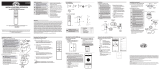
Press and release the button to enable Comfort BreezeTM; this will
change your fan speed randomly, simulating a relaxing breeze. To cancel
this feature press or .
Installation
INSTALLATION AND OPERATION
CEILING FAN REMOTE CONTROL
Safety Information
Warranty
CAUTION: Incorrect wire
connections will damage this
receiver.
The supplier warrants the remote control and receiver to be free from defects in
workmanship and material present at time of shipment from the factory for a period
of one year after the date of purchase by the original purchaser. We agree to correct
such defects without charge or at our option replace with a comparable or superior
model if the product is returned. To obtain warranty service, you must present a
copy of the receipt as proof of purchase. All costs of removing and reinstalling the
product are your responsibility. Damage to any part such as by accident or misuse or
improper installation or by afxing any accessories, is not covered by this warranty.
Servicing performed by unauthorized persons shall render the warranty invalid. There
is no other express warranty. Home Depot hereby disclaims any and all warranties,
including but not limited to those of merchantability and tness for a particular
purpose to the extent permitted by law. The duration of any implied warranty which
cannot be disclaimed is limited to the time period as specied in the express warranty.
Some states do not allow a limitation on how long an implied warranty lasts, so the
above limitation may not apply to you. The retailer shall not be liable for incidental,
consequential, or special damages arising out of or in connection with product use
or performance except as may otherwise be accorded by law. Some states do not
allow the exclusion of incidental or consequential damages, so the above exclusion
or limitation may not apply to you. This warranty gives specic legal rights, and you
may also have other rights which vary from state to state. This warranty supersedes
all prior warranties. Shipping costs for any return of product as part of a claim on the
warranty must be paid by the customer.
Contact the Customer Service Team at 1-800-330-3267
Pre-Installation
TOOLS REQUIRED
Step
ladder
Part Description Quantity
A Remote control 1
B Receiver 1
C AAA 1.5V battery 2
D Plastic wire
connector
5
E Mounting screw 2
F Rubber isolated pad 2
G Wall bracket 1
H Screw covers 2
PACKAGE CONTENTS
IMPORTANT: This product
and/or components
are governed by one or
more of the following
U.S. Patents: 5,947,436;
5,988,580; 6,010,110;
6,046,416, 6,210,117 and
other patents pending.
1
NOTE: The remote control
has already been paired
at factory for your
convenience. If installing
two or more remote
controls in your home,
please follow the steps
below to control each fan
independently.
Pairing the remote control
Operating Fan with the BOND App
1. YOU MUST SET CEILING FAN TO HIGH
SPEED AND LIGHT KIT (IF ANY) TO
THE ON POSITION USING THE PULL
CHAINS (IF APPLICABLE) BEFORE
OPERATING REMOTE CONTROL.
• Remove the battery cover by
pressing firmly on the arrow
and sliding the cover off.
• Install two 1.5V AAA batteries.
• Slide the dip switch in the
battery compartment to the “1”
setting.
• Turn the electrical power to
the fan off then back on at the
breaker box or the wall switch.
• Press and release the “Learn”
button located in the remote’s
battery compartment within
30 seconds of turning the
electrical power to the fan on.
• If pairing is successful, the
fan’s light kit will flash, the
blades will begin to spin and
the fan and light kit will turn
off within 30 seconds.
1Operating the remote control
This equipment has been tested and found to comply with the limits for a Class
B digital device, pursuant to Part 15 of the FCC Rules. These limits are designed
to provide reasonable protection against harmful interference in a residential
installation. This equipment generates, uses and can radiate radio frequency energy
and, if not installed and used in accordance with the instructions, may cause
harmful interference to radio communications. However, there is no guarantee that
interference will not occur in a particular installation. If this equipment does cause
harmful interference to radio or television reception, which can be determined
by turning the equipment off and on, the user is encouraged to try to correct the
interference by one or more of the following measures:
--Reorient or relocate the receiving antenna.
--Increase the separation between the equipment and receiver.
--Connect the equipment into an outlet on a circuit different from that to which the
receiver is connected.
--Consult the dealer or an experienced radio/TV technician for help.
CAUTION:
Any changes or modications not expressly approved by the grantee of this device
could void the user’s authority to operate the equipment.
FCC ID: KUJCE10723
This device complies with Part 15 of the FCC Rules. Operation is subject to the
following two conditions: (1) This device may not cause harmful interference, and (2)
this device must accept any interference received, including interference that may
cause undesired operation.
Press and release the button to turn the light on or off.
Press - to decrease the desired light level.
Press + to increase the desired light level.
1Downloading the BOND HOME App
• Using your smart device, navigate to the application store (Apple App Store
or Google Play). Download the free BOND Home app and create an account.
2Connecting to the BOND Receiver
• Ensure the fan and receiver are receiving power from the house supply by
using the remote control to turn the fan and light on and off.
• Open the BOND Home app on your smart device and follow the instructions
included in the app to add your fan.
Questions, problems, missing parts? Before returning to the store, call
Customer Service 8 a.m. - 7 p.m., EST, Monday-Friday, 9 a.m. - 6 p.m.,
EST Saturday
1-800-330-3267
We appreciate the trust and condence you have placed in us through the
purchase of this remote control. We strive to continually create quality
products designed to enhance your home.
Thank you!
Item #311264804
Model #99434
- Press and release the button to turn the fan on or off.
- Low speed.
- Medium-low speed.
- Medium-high speed.
- High speed.
- Timer
- While the fan is on press button once - turns on a 1 hour run timer.
- While the fan is on press button twice - turns on a 3 hour run timer.
- While the fan is on press button three times - turns on a 6 hour run timer.
- While the fan is on press button four times - cancel the delay feature.
- Light ON/OFF
CAUTION: To reduce the risk of re
or injury, do not use this product
in conjunction with any variable
(rheostat) wall control.
NOTE: The battery will weaken
with age and should be replaced
before leaking takes place as
this will damage the hand unit.
Dispose of the used battery
properly, keep the battery out of
the reach of children.
WARNING: To avoid possible
electrical shock, turn the
electricity off at the main fuse box
before wiring. If you feel you do
not have enough electrical wiring
experience, contact a licensed
electrician.
NOTE: Conrm that your
smart device (phone/tablet)
is connected to your WiFi
network before proceeding.
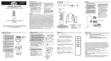
3Installing the receiver
WARNING: To reduce the
risk of re or electric shock,
remember to disconnect
power. The electrical wiring
must meet all local and
national electrical code
requirements. The electrical
source and fan must be
110/120 volt, 60Hz. Do not use
this product in conjunction
with any variable wall control.
Incorrect wire connection can
damage this receiver.
CAUTION: If fan or house wires
are a different color, have this
unit installed by a licensed
electrician.
CAUTION: Do not install in a
damp location or immerse in
water (for indoor use only). Do
not pull on or cut leads shorter.
Do not drop or bump the unit.
Installation (continued)
NOTE: You must set ceiling
fan to high speed and light
kit (if any) to the on position
using the pull chains (if
applicable) before operating
remote control.
NOTE: For better performance
with the WIFI system, the WIFI
antenna must be mounted to
the ceiling outside of the fan’s
ceiling canopy.
• Position the house supply wires
(AAA) to one side of the slide-on
mounting bracket; position the
fan wires (BBB) to the opposite
side.
• Insert the narrow end of the
receiver (as shown, flat side
towards the ceiling) into the
slide-on mounting bracket
until it rests on top of the ball/
downrod assembly. The canopy
comes up to cover the receiver
and bracket.
2Installing the rubber
isolated pads
• Loosen the two screws
provided with the outlet box;
insert two rubber isolated
pads (F) between the mounting
bracket and the outlet box;
firmly tightened the two
screws.
Installation (continued)
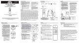
4Wiring the receiver to the household wiring
IMPORTANT: Use the wire
connecting nuts (AA) supplied
with your fan. Secure the
connectors with electrical
tape and ensure there are no
loose strands or connections.
WARNING: Each wire nut
supplied with this fan is
designed to accept up to
one 12-gauge house wire
and two wires from the
fan. If you have larger than
12-gauge house wiring or
more than one house wire
to connect to the fan wiring,
consult an electrician for the
proper size wire nuts to use.
• Spread the wires apart so that
the green and white wires are on
one side of the outlet box and the
black wire is on the other side.
• Connect the green fan wires to
the household ground wire (this
may be a green or bare wire)
using a wire connecting nut (AA).
• Connect the receiver black (or
red) wire to the household black
(hot) wire using a wire connecting
nut (AA).
• Connect the receiver white
wire to the household white
wire (neutral) wire using a wire
connecting nut (AA).
• Secure each wire connecting nut
using electrical tape.
WARNING: To avoid possible
electrical shock, turn the
electricity off at the main
fuse box before wiring. If you
feel you do not have enough
electrical wiring knowledge
or experience, contact a
licensed electrician.
Wiring the fan to the receiver
• Connect the fan motor white wire
to the receiver white wire using a
wire connecting nut (AA).
• Connect the fan motor black wire
to the receiver black wire using a
wire connecting nut (AA).
• Connect the fan motor blue wire to
the receiver blue wire using a wire
connecting nut (AA).
• Secure each wire connecting nut
using electrical tape.
• Turn the wire connecting nut (AA)
upward and push the wiring into
the outlet box (MM).
5
IMPORTANT: Use the wire
connecting nuts (AA)
supplied with your fan.
Secure the connectors with
electrical tape and ensure
there are no loose strands or
connections.
1H 3H 6H
Operating Your Remote Control
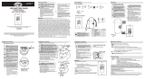
Mounting the transmitter to the wall
6
• Mount the wall bracket (G) to the
wall by using the two mounting
screws (E). Ensure arrow on wall
bracket (G) is pointing upwards.
• Cover the screws by inserting the
screw covers (H) into the screw
holes on the mounting bracket (G).
Wire
cutter
Electrical tape
Phillips
screwdriver
- Fan Speed
Press fan speed button to cycle through the fan’s four speeds. LED’s on the
fan speed button will illuminate to the corresponding speed.
2. The power supply to the remote
control receiver should be
connected through a mains
switch, i.e. existing wall switch.
3. Disconnect from power supply
at breaker box or wall switch
before working on remote control
receiver or ceiling fan.
4. Install receiver into the mounting
bracket/ canopy of the fan to
ensure proper protection.
5. This unit is to be used for the
control of ceiling fan and in a
AC110/120V 60Hz power supply
only.
6. Do not install in damp locations
or immerse in water. (For indoor
use only.)
7. Do not pull on or cut leads shorter.
8. Do not drop or bump the unit.
9. Do not mix old and new batteries.
10. Do not mix alkaline, standard
(carbon-zinc), or rechargeable (ni-
cad, ni-mh, etc.) batteries. D
C
F
E
AB
G
1H 3H 6H
H
F
Outlet box
Mounting
Bracket
AAA BBB
VIEW AFTER
INSTALLATION
WIFI antenna mount
outside of the canopy
WIFI
antenna
Receiver
antenna
WIFI
antenna
Receiver antenna
(Leave connected
and do not cut)
Black
(or Red)
Black
Green
(or Bare)
Green
Outlet Box
in the ceiling
(MM)
Antenna
White
B
AA (x3)
Installation (continued)
B
Blue
Antenna
Black White
Green
AA (x3)
Outlet Box
in the ceiling
(MM)
E
B
G
G
H
1H 3H 6H

- Presionar y soltar el botón para encender o apagar el ventilador.
-
Comfort Breeze
TM
- Presionar y soltar el el botón para activar la función
Comfort Breeze
TM
; esto hará que la velocidad del ventilador cambie aleatoriamente,
imitando una brisa relajante. Para cancelar esta función, presionar o .
Instalación
INSTALACIÓN Y OPERACIÓN
CONTROL REMOTO PARA VENTILADOR DE TECHO
Información de seguridad
Garantía
PRECAUCIÓN:
Conectar el cableado
de manera incorrecta dañará este
receptor.
El proveedor garantiza que el control remoto y el receptor no presentan defectos de fabricación
ni de materiales, al momento en que es enviado desde la fábrica, por un período de un año a
partir de la fecha de adquisición por el comprador original. Si el producto es devuelto, aceptamos
reparar sus defectos sin cargo alguno o, a nuestra entera discreción, reemplazarlo por modelo
similar o superior. Para obtener servicio de garantía tiene que presentarse una copia del recibo
como comprobante de compra. Todos los costos de retiro y reinstalación del producto correrán
por cuenta del cliente. No están cubiertos por esta garantía los daños a ninguna de las piezas
como resultado de accidente, instalación o uso incorrectos, ni por jación de cualquier accesorio.
Cualquier servicio prestado por personal no autorizado invalidará la garantía. No hay ninguna
otra garantía expresa. Por este medio The Home Depot queda exento de todas y cada una de
las garantías, incluyendo, pero sin limitarse a, aquellas de comercialización e idoneidad para un
n particular, en el alcance permitido por la ley. La duración de cualquier garantía implícita que
no pueda exonerarse se limita al plazo especicado en la garantía explícita. Algunos estados no
permiten limitar la duración de la garantía, así que la limitación anterior pudiera no aplicarse
a su caso. El minorista no será responsable por daños directos, indirectos ni especiales que
resulten o deriven del uso o funcionamiento del producto, excepto en los casos que pudieran
estar estipulados de otro modo por ley. Algunos estados no permiten excluir ni limitar daños
directos o indirectos, así que la limitación o exclusión anterior pudiera no aplicarse a su caso.
Esta garantía concede derechos legales especícos y es posible que usted tenga también otros
derechos, que varían de estado a estado. Esta garantía sustituye todas las precedentes. Los
costos de envío en cualquier devolución de productos como parte de una reclamación tienen
que ser pagados por el cliente.
Comunicarse con el Equipo de Servicio al Cliente: 1-800-330-3267
Preinstalación
HERRAMIENTAS NECESARIAS
Pieza
o
parte Descripción Cantidad
A Control remoto 1
B Receptor 1
CBatería AAA de
1.5 V 2
D
Conector plástico
para cables
5
ETornillo de
montaje 2
FAlmohadilla
aislante de goma 2
GSoporte de pared 1
Hcubiertas de
tornillo 2
CONTENIDO DEL PAQUETE
IMPORTANTE:
Este producto
y/o sus componentes están
protegidos por una o más de
las siguientes patentes de los
EE. UU.: 5,947,436; 5,988,580;
6,010,110; 6,046,416, 6,210,117,
así como otras patentes
pendientes.
1
NOTA:
Para tu conveniencia,
el control remoto viene ya
emparejado de fábrica con el
ventilador de techo. Si vas a
instalar dos o más controles
remotos en tu hogar, favor de
seguir los pasos más abajo
para controlar cada uno con
independencia del otro.
Cómo congurar el control remoto
Cómo operar el ventilador con la aplicación (app) BOND
1. HAY QUE CONFIGURAR EL INTERRUPTOR
DEL VENTILADOR DE TECHO EN
VELOCIDAD ALTA Y EL KIT DE LUCES (SI LO
TIENE) EN LA POSICIÓN ON USANDO LAS
CADENAS DE HALAR (SI CORRESPONDE)
ANTES DE OPERAR EL CONTROL REMOTO.
• Quita la cubierta de la batería
presionando con rmeza sobre la
echa y deslizando la cubierta hasta
liberarla.
• Instalar dos baterías AAA de 1.5 V.
• Desliza el interruptor del
compartimiento de las baterías a la
conguración “1”.
• Desconectar la corriente eléctrica al
ventilador y seguidamente ponerla
de nuevo en la caja de cortacircuitos
o en el interruptor de pared.
• Presionar y soltar el botón “Learn”
en el compartimiento de la batería
del control remoto dentro de los 30
segundos siguientes al retorno de la
corriente eléctrica al ventilador.
• Si el emparejamiento es exitoso,
el kit de luces del ventilador
parpadeará, las aspas comenzarán a
girar, y tanto el ventilador como el kit
de luces se apagarán en el plazo de
30 segundos.
1Cómo operar el control remoto
Este equipo ha sido probado y se determinó que cumple con los límites establecidos
para un dispositivo digital Clase B, de acuerdo con la Parte 15 de las Normas de la FCC.
Estos límites fueron establecidos para dar protección razonable contra la interferencia
dañina en uso residencial. Este equipo genera, consume y puede irradiar energía de
radiofrecuencia; si no se instala y usa de acuerdo con las instrucciones, puede causar
interferencia nociva a comunicaciones radiales. Sin embargo, no hay garantía de que no
ocurrirá interferencia en cierta instalación particular. Si este equipo causa interferencia
perjudicial a la recepción de radio o televisión, que puede determinarse encendiendo y
apagando el equipo, se recomienda al usuario tratar de corregir la interferencia con una
o más de las siguientes medidas:
– Reorientar o reubicar la antena receptora.
– Incrementar la distancia entre los equipos y el receptor.
– Conectar el equipo a un tomacorriente en circuito distinto del receptor.
– Consultar al concesionario o a un técnico de radio/TV con experiencia para ayuda.
PRECAUCIÓN:
Los cambios o modicaciones sin aprobación expresa del responsable de este dispositivo
podrían anular el derecho del usuario a operar el equipo.
ID de FCC: KUJCE10723
Este dispositivo cumple con la Parte 15 de las Normas FCC. Su operación está sujeta a
las dos condiciones siguientes: (1) Este dispositivo no debe causar interferencia dañina
y (2) tiene que aceptar cualquier interferencia recibida, incluyendo aquella que pudiera
afectar su funcionamiento.
Oprime y suelta el botón para encender o apagar la luz.
Presiona para reducir el nivel de luz deseado.
Presionar + para incrementar el nivel deseado de luz.
1Cómo descargar la aplicación (app) BOND HOME
• Usando tu dispositivo inteligente, navegar al almacén de aplicaciones (Apple
App o Google Play). Descarga gratis la aplicación (app) BOND Home y crea una
cuenta.
2Cómo conectar al receptor BOND
• Garantizar que al ventilador y al recibidor llega la corriente eléctrica de la línea
de suministro doméstico, usando el control remoto para apagar y encender el
ventilador y la luz.
• Abrir en tu dispositivo inteligente la aplicación (app) BOND Home y seguir las
instrucciones dadas en aplicación (app) para agregar tu ventilador.
¿Preguntas, problemas, partes o piezas faltantes? Antes de devolver a la
tienda, llama al Servicio al Cliente: de lunes a viernes, entre 8:00 a.m. y
7:00 p.m. (hora del Este),
y los sábados de 9:00 a.m. a 6:00 p.m. (hora del Este).
1-800-330-3267
Apreciamos la plena conanza que has depositado en nosotros al
comprar este control remoto. Nos esforzamos en crear continuamente
productos de calidad diseñados para mejoras del hogar.
¡Gracias!
Artículo #311264804
Modelo #99434
- Velocidad baja
- Velocidad media-baja.
- Velocidad media-alta.
- Velocidad alta
- Temporizador
- Con el ventilador encendido, oprime una vez el botón para activar el
temporizador con 1 hora de funcionamiento.
- Con el ventilador encendido, oprime dos veces el botón para activar el
temporizador con 3 horas de funcionamiento.
- Con el ventilador encendido, oprime tres veces el botón para activar el
temporizador con 6 horas de funcionamiento.
- Con el ventilador encendido, oprime cuatro veces el botón para cancelar la
función de encendido diferido.
- Luz encendida/apagada (ON/OFF)
PRECAUCIÓN:
Para reducir el riesgo
de incendio o lesiones, no utilices
este producto con ningún control de
pared variable (reóstato).
NOTA:
La batería se debilitará con
el tiempo y deberá ser reemplazada
antes de que se produzca alguna
fuga, ya que esto dañará la unidad
de mano. Desecha bien la batería
usada y mantén toda batería fuera
del alcance de los niños.
ADVERTENCIA: Para evitar una
posible descarga eléctrica hay que
desconectar la electricidad en la
caja principal de fusibles antes
de cablear. Si crees que no tienes
suciente experiencia en cableado
eléctrico, contacta a un electricista
con licencia.
NOTA:
Conrmar que tu
dispositivo inteligente (teléfono/
tableta) está conectado a tu red
WiFi antes de proceder.
3Cómo instalar el receptor
ADVERTENCIA:
Para reducir el
riesgo de incendio o de descarga
eléctrica, recuerda desconectar la
electricidad. El cableado eléctrico
tiene que cumplir todos los
requisitos de los códigos eléctricos
nacionales y locales. La fuente
de energía y el ventilador tienen
que ser de 110/120 V y 60 Hz. No
utilizar este producto con ningún
control variable de pared. Conectar
el cableado de manera incorrecta
dañará este receptor.
PRECAUCIÓN:
Si los cables del
ventilador o del hogar son de color
diferente, haz que un electricista
con licencia instale esta unidad.
PRECAUCIÓN
: No instales en
lugares húmedos ni sumerjas en
agua (solo para uso en interiores).
No hales ni recortes los cables
terminales. No dejes caer ni
golpees la unidad.
Instalación (continuación)
NOTA:
Tienes que congurar el
ventilador de techo en velocidad
alta y el kit de luces (si lo tiene)
en la posición ON usando las
cadenas de halar (si corresponde)
antes de operar el control remoto.
NOTA:
Para mejor rendimiento
con el sistema WIFI, la antena WIFI
tiene que montarse al cielo raso
fuera de la cubierta del ventilador
de techo.
• Colocar los cables de suministro del
hogar (AAA) a un lado del soporte
de montaje deslizante; colocar los
cables del ventilador (BBB) en el
lado opuesto.
• Inserta el extremo angosto del
receptor (como se muestra: el lado
plano hacia el techo) en el soporte
de montaje deslizante hasta dejarlo
apoyado en la parte superior del
conjunto tubo bajante/esfera. La
cubierta viene para cubrir hasta el
receptor y el soporte.
2Cómo instalar las almohadillas aislantes de goma
• Aojar los dos tornillos incluidos
con la caja eléctrica; insertar dos
almohadillas aislantes de goma (F)
entre el soporte de montaje y la
caja eléctrica; apretar rmemente
los dos tornillos.
Instalación (continuación)
4Cómo cablear el receptor al cableado del hogar
IMPORTANTE: Usa las tuercas de
conexión de cables (AA)
incluidas con el ventilador.
Sujeta los conectores con cinta
de electricista y asegúrate de
que no haya conexiones ni
cables sueltos.
ADVERTENCIA:
Cada cable no
incluido con este ventilador
debe estar diseñado para
aceptar hasta un cable eléctrico
doméstico calibre 12 y dos
cables del ventilador. Si tienes un
cableado doméstico que exceda
del calibre 12 o más de un cable
doméstico para conectar al
cableado del ventilador, consulta
a un electricista para el tamaño
adecuado de las tuercas a usar.
• Separa los cables de manera que
los cables verde y blanco queden
de un lado de la caja eléctrica y el
cable negro quede del otro lado.
• Conecta los cables verdes del
ventilador al cable de conexión a
tierra de la casa (este puede ser
verde o pelado) con una tuerca de
conexión de cables (AA).
• Conecta el cable negro (o rojo) del
receptor al cable negro del hogar
(positivo), usando una tuerca de
conexión de cables (AA).
• Conecta el cable blanco del receptor
al cable blanco del hogar (neutro),
usando una tuerca de conexión de
cables (AA).
• Asegura cada tuerca de conexión de
cables con cinta de electricista.
ADVERTENCIA:
Para evitar una
posible descarga eléctrica hay
que desconectar la electricidad
en la caja principal de fusibles
antes de cablear. Si crees que no
tienes suciente conocimiento
o experiencia sobre cableado
eléctrico, contacta a un
electricista certicado.
Cómo cablear el ventilador al receptor
• Conecta el cable blanco del motor
del ventilador al cable blanco del
receptor usando una tuerca de
conexión de cables (AA).
• Conecta el cable negro del motor
del ventilador al cable negro del
receptor usando una tuerca de
conexión de cables (AA).
• Conecta el cable azul del motor del
ventilador al cable azul del receptor
usando una tuerca de conexión de
cables (AA).
• Asegura cada tuerca de conexión de
cables con cinta de electricista.
• Gira la tuerca de conexión de
cables (AA) hacia arriba y coloca el
cableado dentro de la caja eléctrica
(MM).
5
IMPORTANTE:
Usa las tuercas
de conexión de cables (AA)
incluidas con el ventilador.
Sujeta los conectores con cinta
de electricista y asegúrate de
que no haya conexiones ni
cables sueltos.
1H 3H 6H
Cómo usar el control remoto
Cómo montar el transmisor
en la pared
6
• Montar el soporte de pared (G)
en ella usando los dos tornillos
de montaje (E). Garantizar que la
echa en el soporte de pared (G)
apunte hacia arriba.
• Cubra los tornillos insertando las
cubiertas de los tornillos (H) en los
oricios para tornillos en el soporte
de montaje (G).
- Velocidad del ventilador
Presionar el botón de velocidad para pasar por sus cuatro opciones Las luces
LED en el botón de velocidad del ventilador indicarán aquella correspondiente.
2. El suministro de corriente al receptor de
control remoto debe conectarse a través
de un interruptor principal, es decir,
un interruptor de pared preexistente.
3. Desconectar el suministro de corriente
en la caja de cortacircuitos o en el
interruptor de pared antes de trabajar
con el receptor de control remoto o el
ventilador de techo.
4. Instalar el receptor en el soporte de
montaje / cubierta del ventilador para
garantizar la protección adecuada.
5. Esta unidad debe usarse solamente
para controlar ventiladores de techo en
una fuente de corriente de CA
de 110/120 V y 60 Hz.
6. No instalar en lugares húmedos ni
sumergir en agua. (Sólo para uso en
interiores).
7. No hales ni recortes los cables
terminales.
8. No dejes caer ni golpees la unidad.
9. No mezclar baterías viejas y nuevas.
10. No mezclar baterías alcalinas, estándar
(carbón-cinc) ni recargables (Ni-Cad,
Ni-Mh y otras).
D
C
F
E
AB
G
1H 3H 6H
H
F
Outlet box
Mounting
Bracket
AAA BBB
VIEW AFTER
INSTALLATION
WIFI antenna mount
outside of the canopy
WIFI
antenna
Receiver
antenna
WIFI
antenna
Receiver antenna
(Leave connected
and do not cut)
Black
(or Red)
Black
Green
(or Bare)
Green
Outlet Box
in the ceiling
(MM)
Antenna
White
B
AA (x3)
Instalación (continuación)
B
Blue
Antenna
Black White
Green
AA (x3)
Outlet Box
in the ceiling
(MM)
E
B
G
G
H
1H 3H 6H
Escalera
de tijera
CortacablesCinta
de electricista
Destornillador
Phillips
Caja eléctrica
en el cielo raso
(MM)
Verde
(o pelado)
Antena
Verde
Blanco
Negro
Negro
(o rojo)
Caja eléctrica
en el cielo raso
(MM)
Verde
Antena
Negro Blanco
Azul
Soporte
de montaje
Caja eléctrica
VISTA DESPUÉS
DE LA
INSTALACIÓN
La antena WIFI
montada fuera
de la cubierta
Antena
receptora
Antena
WIFI
Antena del receptor
(Dejar conectada
y no cortar)
Antena
WIFI
/