Alamo Industrial Rear Mount Boom 165 & 180 Manual de usuario
- Categoría
- Cortadoras de césped
- Tipo
- Manual de usuario

© 2020 Alamo Group Inc.
Published 02/20 Part No. 32120321C
OPERATOR’S MANUAL
ALAMO INDUSTRIAL
®
1502 E. Walnut
Seguin, Texas 78155
830-372-3551
E-mail: [email protected]
This Operator's Manual is an
integral part of the safe operation of
this machine and must be
maintained with the unit at all times.
READ,
UNDERSTAND, and
FOLLOW
the Safety and Operation
Instructions contained in this
manual before operating the
equipment. C01-Cover_A
Important Operating
and Safety
Instructions are found
in the Mower Safety
Video that can be
instantly accessed on
the Internet at:
www.algqr.com/ave
$0.00
REAR MOUNT BOOM MOWER
RM180/
RM165


In order to reduce accidents and enhance the safe operation of mowers, Alamo Industrial, in cooperation with other
industry manufacturers has developed the AEM/FEMA Industrial and Agricultural Mower Safety Practices video
and guide book.
The video will familiarize and instruct mower-tractor operators in safe practices when using industrial and
agricultural mowing equipment. It is important that Every Mower Operator
be educated in the operation of their
mowing equipment and be able to recognize the potential hazards that can occur while operating a mower. This
video, along with the mower operator’s manual and the warning messages on the mower, will significantly assist in
this important education.
Your Authorized Alamo Industrial Dealer may have shown this video and presented you a DVD Video when you
purchased your mower. If you or any mower operator have not seen this video, Watch the Video, Read this
Operator’s Manual, and Complete the Video Guidebook before operating your new mower. If you do not
understand any of the instructions included in the video or operator’s manual or if you have any questions
concerning safety of operation, contact your supervisor, dealer or Alamo Industrial.
Video at (830) 372-9529 or mail in a completed copy of the form on the back of this page to AEM VHS Video 1502
E Walnut Street, Seguin, TX 78155. and request the VHS video version. Please include your name, mailing
address, mower model and serial number.
Every operator should be trained for each price of equipment (Tractor and Mower), Understand the intended use,
and the potential hazards before operating the equipment.
The information and material listed above along with this Operator’s Manual can assist you in meeting the OSHA
requirement for Operator annual training.
OSHA TRAINING REQUIREMENTS
The following training requirements have been taken from Title 29, Code of Federal Regulations Part
1928.57 (a)(6). www.osha.gov
Operator Instructions. At the time of initial assignment and at least annually thereafter, the employer shall instruct
every employee who operates an agricultural tractor or implement in the safe operating practices and servicing of
equipment with which they are or will be involved, and of any other practices dictated by the work environment.

Alamo Industrial Division is willing to provide
one (1) AEM Mower Safety Practices Video
Please Send Me: VHS Format – AEM/FEMA Mower Operator Safety Video
DVD Format – AEM/FEMA Mower Operator Safety Video
Mower Operator’s Manual
AEM Mower Operator’s Safety Manual
Requester Name:__________________________________Phone:
________________________________
Requester Address:_________________________________________________
City:________________________________________
State:_______________________________________
Zip Code:___________________________________
Mower Model: _________________________Serial Number:_______________________________
Date Purchased:________________________ Dealer Salesperson:___________________________
Dealership Name:_______________________Dealership Location:__________________________
Mail to:
AEM Video Services
1502 E. Walnut Street
Seguin, TX 78155
Or Fax to:
(830) 372-9529
Or E-mail to:
AEMVideo@alamo-group.com

To the Owner/Operator/Dealer
This Operator's Manual is an integral part of the safe operation of this machine and must be maintained with the
implement at all times. A Manual canister is provided on the implement where this manual can be properly stored.
If you lose or damage this manual a free replacement manual can be obtained from an authorized Alamo Industrial
dealer or by down loading the manual from the Alamo Industrial website www.www.alamo-industrial.com
BEFORE YOU START! READ, UNDERSTAND, and FOLLOW the information provided in this manual, the AEM
Mower Safety manual and the tractor operator's manual carefully to learn how to operate and service your machine
properly. Failure to do so could result in personal injury to you and bystanders. All implements with moving parts
are potentially hazardous. Every effort has been made to ensure that the machine is safe but operators must avoid
engaging in unsafe practices and follow the written instructions provided. The manufacturer has designed this
implement to be used with all its safety equipment properly attached to minimize the chance of accidents.
SAFETY FIRST. Completely read and understand the safety section of this manual before operating this
equipment. Do not allow anyone to operate this equipment who has not fully read and understood this manual.
Contact your Dealer to explain any instructions that you do not fully understand.
The care you give your Alamo Industrial Implement will greatly determine your satisfaction with its performance and
its service life. Carefully read and follow the instructions in this manual to provide you with a thorough
understanding of your new implement and its intended use and service requirements.
All references made in this manual to right, left, front, rear, top or bottom are as viewed facing the direction of
forward travel with the implement properly attached to the tractor.
Replacement Parts information is located in a separate Parts Manual. Alamo Industrial mowers use balanced and
matched system components for blade carriers, blades, cuttershafts, knives, knife hangers, rollers, drivetrain
components, and bearings. These parts are made and tested to Alamo Industrial specifications. Non-genuine “will
fit” parts do not consistently meet these specifications. The use of “will fit” parts may reduce mower performance,
void warranties, and present a safety hazard. Use genuine Alamo Industrial mower parts for economy and safety.
For future reference, record your Alamo Industrial product model number and serial number.
Dealer Telephone Model Number
Owner Purchase Date Serial Number
Serial Number Plate

DEALER to CUSTOMER Pre-Delivery/ Operation Instructions
Dealer should inform the Purchaser of this product of Warranty terms, provisions, and procedures that are
applicable. Dealer should inform Purchaser to review the contents of the Operator’s Manual including safety
equipment, safe operation and maintenance, to review the Safety Signs on the implement (and tractor if possible)
and of Purchaser’s responsibility to train his/her operators’s of safe operation procedures.
• IMPLEMENTS: I have explained that Deflectors, Chain Guards, or Solid Skirts must be installed and main-
tained in good repair.
• DRIVELINES: I have made certain that all driveline, gearbox, and other shields are in good repair and fas-
tened securely in place to prevent injuries from entanglement or thrown objects.
• HYDRAULIC MACHINES: I have explained the necessity of using clean hydraulic oil, changing filters as
instructed, stopping leaks, damage caused by operating with over-heated oil, caring for hoses, using hoses of
proper rating, maintaining the specified operating pressure and the potential hazard of oils penetrating the
skin.
• BOOM TYPE or FOLDING-TYPE IMPLEMENTS: I have explained that it is not possible to guard against
thrown objects when the head is lifted off ground and that operator is responsible to watch out for persons in
the area. I have explained that the lifted mower head or boom can contact overhead obstructions with damage
to cables and telephone lines and possible injury. I have explained that the extended head or boom or
retracted boom can contact power lines resulting in electrocution, injury or death and that operator is responsi-
ble for keeping clear of such hazards.
PRE-DELIVERY SERVICE
CHECK AND ADJUST OR LUBRICATE AS REQUIRED
See Operator’s Manual for Details
Inspection Performed - Warranty and Safety Procedures Explained - Installation Complete
LUBRICATION & HYDRAULICS
Gearbox (Oil Levels)
Hydraulic Oil Level (External Tank)
Tractor Hydraulic Oil Level
Hydraulic Hoses (Not Kinked Tighten Connections)
Front Pump Drive (Assembly Is Tight And Shaft Properly
Aligned)
MOWER
Spindle And Motor Bolts Properly Torqued
Spindle Oil Level
Blade Carrier Bolts Properly Torqued/Retaining Pin In
Place
Mower Cutting Height And Level Adjusted
Cutting Shaft Bearings Lubricated
All Hardware Properly Torqued
Tire and Air Pressure/Lug Nuts (Correct Torque)
Wheel Bearings (Check, Grease, and Preload)
ATTACHMENTS & INSTALLATION
Deflectors Front And Rear
Shredding Attachments
Correct Blade Rotation Direction
Axle Arms And Beams
Tongue And Control Rods (Installed And Adjusted)
All Bolts - Pins And Nuts (Proper Torque)
MOWER TO TRACTOR CONNECTIONS
Draw Bar Length (Check And Set)
A-Frame Pivot & Links
Control Rods (Adjusted Equal)
Axle Height (Adjusted)
Cutting Height (Adjust)
Mount Kit-Pre-Operation Check Complete
Mower Wing (Adjust Level With The Center)
Mower Wing (Check For Proper Raising Operation)
C.V. Drivelines (Check Max Turn Radius)
Pull Type Hitch (Height Adjustment)
Mounting Hardware Properly Torqued
SAFETY ITEMS
Protective Shields (Operation And Installation)
Driveline Clutch (Torque Limiter) (Adjust And Run In)
Safety Decals (Installed)
Operator’s Manual (Supplied)
Tractor PTO Shield (Installed)
S.M.V. Emblem (Installed If Needed)
Tongue Jack (Installation and Operation)
Safety Tow Chain (Installed)
ADMA Driveline Safety Manual Supplied
AEM Mower Safety Manual (Supplied in Canister)
AEM Mower Safety Video has been shown to Purchaser

TABLE OF CONTENTS
SAFETY SECTION .............................................................................................................. 1-1
GENERAL SAFETY INSTRUCTIONS AND PRACTICES ................................................................................. 1-2
Operator Safety .................................................................................................................................................. 1-3
CRUSHING HAZARDS ...................................................................................................................................... 1-4
CONNECTING OR DISCONNECTING IMPLEMENT SAFETY ........................................................................ 1-5
THROWN OBJECTS HAZARDS ....................................................................................................................... 1-6
RUN OVER HAZARDS ...................................................................................................................................... 1-8
PTO ENTANGLEMENT HAZARDS ................................................................................................................... 1-9
MOWER BLADE CONTACT HAZARDS ......................................................................................................... 1-10
HIGH PRESSURE OIL LEAK HAZARD .......................................................................................................... 1-11
ELECTRICAL & FIRE HAZARDS ....................................................................................................................1-12
TRANSPORTING HAZARDS .......................................................................................................................... 1-13
HAZARDS WITH MAINTENANCE OF IMPLEMENT ...................................................................................... 1-14
PARTS INFORMATION ................................................................................................................................... 1-15
Decal Location ................................................................................................................................................. 1-15
ROTARY HEAD ............................................................................................................................................... 1-20
Decal Description ............................................................................................................................................. 1-21
FEDERAL LAWS AND REGULATIONS .......................................................................................................... 1-32
INTRODUCTION SECTION ................................................................................................. 2-1
ASSEMBLY SECTION ........................................................................................................ 3-1
TRACTOR SELECTION .................................................................................................................................... 3-2
Linkage Requirements ....................................................................................................................................... 3-2
Linkage Isolation ................................................................................................................................................ 3-2
Check Chains/ Stabilizers .................................................................................................................................. 3-2
Tractor Relief Valve ........................................................................................................................................... 3-2
Tractor Hydraulic Flow Rates .............................................................................................................................3-2
P.T.O. Shaft ....................................................................................................................................................... 3-2
Draft Control ....................................................................................................................................................... 3-2
TRACTOR PREPARATION ............................................................................................................................... 3-3
Fitting Operator Guard ....................................................................................................................................... 3-3
Wheel Width ....................................................................................................................................................... 3-4
Ballast Weight .................................................................................................................................................... 3-4
DEALER SETUP INSTRUCTIONS .................................................................................................................... 3-4
ATTACHMENT TO TRACTOR .......................................................................................................................... 3-4
HEAD ATTACHMENT ..................................................................................................................................... 3-10
CYCLE TIMES – BOOM FUNCTION SPEED ................................................................................................. 3-11
FITTING CONTROL UNIT IN CAB .................................................................................................................. 3-11
OIL REQUIREMENTS ..................................................................................................................................... 3-12
Tank ................................................................................................................................................................. 3-12
Gearbox ........................................................................................................................................................... 3-12
RUNNING UP PROCEDURE .......................................................................................................................... 3-13
RM180/165 ...................................................................................................................................................... 3-13
RM180/165 ...................................................................................................................................................... 3-13
REMOVAL FROM TRACTOR ......................................................................................................................... 3-14
OPERATION SECTION ....................................................................................................... 4-1
Standard Equipment and Specifications ............................................................................................................ 4-3

OPERATOR REQUIREMENTS ......................................................................................................................... 4-4
TRACTOR REQUIREMENTS ............................................................................................................................ 4-5
ROPS and Seat Belt .......................................................................................................................................... 4-5
Operator Thrown Object Protection ................................................................................................................... 4-5
Tractor Lighting and SMV Emblem .................................................................................................................... 4-6
Tractor Ballast .................................................................................................................................................... 4-6
Tractor Safety Devices ....................................................................................................................................... 4-7
Tractor Horsepower ........................................................................................................................................... 4-7
3-Point Hitch ...................................................................................................................................................... 4-7
Hydraulics .......................................................................................................................................................... 4-7
Front End Weight .............................................................................................................................................. 4-8
Power Take Off (PTO) ....................................................................................................................................... 4-8
GETTING ON AND OFF THE TRACTOR ......................................................................................................... 4-8
Boarding the Tractor .......................................................................................................................................... 4-9
Dismounting the Tractor .................................................................................................................................... 4-9
STARTING THE TRACTOR ............................................................................................................................ 4-10
Connecting Attaching Head to Boom ............................................................................................................... 4-11
Connecting Mower Head Hydraulics ................................................................................................................ 4-11
PRE-OPERATION INSPECTION AND SERVICE ........................................................................................... 4-13
Tractor Pre-Operation Inspection/Service ........................................................................................................4-13
OPERATING THE BOOM MOWER- MACHINE CONTROLS ......................................................................... 4-21
Cable Controls ................................................................................................................................................. 4-21
Arm and Head Movement ................................................................................................................................ 4-22
Head Angle Float (Optional Extra) ................................................................................................................... 4-22
Electric Monolever Control ............................................................................................................................... 4-23
Arm and Head Movement ................................................................................................................................ 4-24
Head Angle Float (Optional Extra) ................................................................................................................... 4-24
Rotor Controls (Ti Only) ................................................................................................................................... 4-25
Engaging Drive ................................................................................................................................................ 4-26
Rotor Operating Speed .................................................................................................................................... 4-26
Forward Speed ................................................................................................................................................ 4-27
Tractor Position ................................................................................................................................................ 4-27
Operating Speed ..............................................................................................................................................4-27
Working Close In and High .............................................................................................................................. 4-27
High Voltage Cables ........................................................................................................................................ 4-28
For Downward Cutting ..................................................................................................................................... 4-28
Roller Positions ................................................................................................................................................ 4-30
DRIVING THE TRACTOR AND IMPLEMENT ................................................................................................. 4-31
Starting the Tractor .......................................................................................................................................... 4-32
Brake and Differential Lock Setting .................................................................................................................. 4-33
Driving the Tractor and Boom .......................................................................................................................... 4-34
OPERATING THE TRACTOR AND IMPLEMENT ........................................................................................... 4-35
OPERATING INSTRUCTIONS ........................................................................................................................ 4-35
Foreign Debris Hazards ................................................................................................................................... 4-37
Bystanders/Passersby Precautions ................................................................................................................. 4-37
Engaging the Power Take Off (PTO) ............................................................................................................... 4-38
Operating Speed and Ground Speed .............................................................................................................. 4-39
Operating the Mower ....................................................................................................................................... 4-39
Operating the Attached Mower Heads ............................................................................................................. 4-41
Shutting Down the Attached Head with Levers ................................................................................................ 4-43
Shutting Down the Attached Head with Joystick .............................................................................................. 4-44
TRACTOR, BOOM, AND ATTACHED HEAD STORAGE ............................................................................... 4-45
DISCONNECTING THE MOWER ................................................................................................................... 4-45
TRANSPORTING THE TRACTOR AND IMPLEMENT ................................................................................... 4-46
Transporting on Public Roadways ................................................................................................................... 4-46
Hauling the Tractor and Implement .................................................................................................................. 4-49

TROUBLESHOOTING GUIDE ........................................................................................................................ 4-50
MAINTENANCE SECTION .................................................................................................. 5-1
HAZARDS WITH MAINTENANCE OF IMPLEMENT ........................................................................................ 5-2
LUBRICATION ................................................................................................................................................... 5-3
HYDRAULIC SYSTEM ...................................................................................................................................... 5-5
Oil Supply ........................................................................................................................................................... 5-5
Filtration Maintenance ........................................................................................................................................ 5-5
HYDRAULIC HOSES ......................................................................................................................................... 5-6
Hose Replacement ............................................................................................................................................ 5-6
Hose Warranty ................................................................................................................................................... 5-6
HOSE CONNECTIONS ..................................................................................................................................... 5-7
Main Control Valve (Cable Models) ................................................................................................................... 5-7
Main Control Valve (Electric Models) ................................................................................................................. 5-8
Boom Cylinder Removal and Replacement Instructions .................................................................................. 5-10
Hydraulic Component Maintenance Schedule ................................................................................................. 5-11
P.T.O. GEARBOX ............................................................................................................................................ 5-12
CABLES ........................................................................................................................................................... 5-12
STORAGE ....................................................................................................................................................... 5-12
PROPER TORQUE FOR FASTENERS .......................................................................................................... 5-12
Service of Spindle Housing .............................................................................................................................. 5-14
Assembly ......................................................................................................................................................... 5-15
Maintenance .................................................................................................................................................... 5-16
FLAILHEAD ..................................................................................................................................................... 5-16
Flail Blades Inspection ..................................................................................................................................... 5-17
Blade Pins and D-Ring Inspection ................................................................................................................... 5-18
General Information on Flail Mower Vibration .................................................................................................. 5-19


Safety Section 1-1
© 2020 Alamo Group Inc.
SAFETY SECTION

SAFETY
RM180/160 02/20 Safety Section 1-2
© 2020 Alamo Group Inc.
SAFETY
GENERAL SAFETY INSTRUCTIONS AND PRACTICES
A careful operator is the best operator. Safety is of primary importance to the manufacturer and should be to
the owner/operator. Most accidents can be avoided by being aware of your equipment, your surroundings,
and observing certain precautions. The first section of this manual includes a list of Safety Messages that, if
followed, will help protect the operator and bystanders from injury or death. Read and understand these
Safety Messages before assembling, operating or servicing this Implement. This equipment should only be
operated by those persons who have read the manual, who are responsible and trained, and who know how
to do so responsibly.
The Safety Alert Symbol combined with a Signal Word, as seen below, is used throughout this
manual and on decals which are attached to the equipment. The Safety Alert Symbol means:
“ATTENTION! BECOME ALERT! YOUR SAFETY IS INVOLVED!” The Symbol and Signal Word
are intended to warn the owner/operator of impending hazards and the degree of possible injury
faced when operating this equipment.
Practice all usual and customary safe working precautions and above all---remember safety is up to YOU
.
Only YOU
can prevent death or serious injury from unsafe practices.
Indicates a hazardous situation that, if not avoided, WILL result in DEATH OR VERY
SERIOUS INJURY.
Indicates a hazardous situation that, if not avoided, COULD result in DEATH OR
SERIOUS INJURY.
Indicates a hazardous situation that, if not avoided, MAY result in MINOR OR
MODERATE INJURY.
Indicates information considered important, but not hazard-related (e.g. messages
relating to property damage).
NOTE: Identifies points of particular interest for more efficient and convenient operation or repair.
READ, UNDERSTAND, and FOLLOW the following Safety Messages.
Death or serious injury may occur unless care is taken to follow the
warnings and instructions stated in this Manual and in the Safety
Messages on the implement. Always follow the instruction in this manual
and use good common sense to avoid hazards.
Pictographs are used throughout this manual to help bring your visual
attention to safety issues.
NOTE: If you want a translation of this safety section in one of the following Languages, please contact:
Translations at 1502 E. Walnut Street Seguin, TX 78155; Fax: (830) 372-9529; Safety Section Translations
are available in Spanish, Portuguese, French, German, Russian.
PN GS-01

SAFETY
RM180/160 02/20 Safety Section 1-3
© 2020 Alamo Group Inc.
SAFETY
Operator Safety
TO AVOID DEATH OR SERIOUS INJURY DO THE FOLLOWING:
• READ, UNDERSTAND and FOLLOW Operator's Manual instructions, Warnings and Safety Messages.
• WEAR SAFETY GLASSES with side shields (marked with ANSI Z87), safety shoes, hard hat, hearing protection and gloves when
operating or repairing equipment
• WEAR appropriate breathing respirator when operating in dusty conditions to avoid respiratory diseases.
• DO NOT WEAR loose clothing or jewelry to avoid rotating parts entanglement injury.
• DO NOT USE DRUGS or ALCOHOL before or while operating equipment.
• DO NOT ALLOW anyone to operate equipment under the influence of drug or alcohol.
• CONSULT medical professional for medication impairment side effects.
• STAY CLEAR of hot surfaces such as Mufflers, hydraulic pumps, valves and tanks.
• STAY ALERT, prolonged operation can cause fatigue, STOP and REST.
GENERAL OPERATING SAFETY
VISIBILITY CONDITIONS WHEN MOWING:
• OPERATE IN DAYLIGHT or with lights that gives at least 100 yards clear visibility.
• BE ABLE TO SEE and identify passersby, steep slopes, ditches, drop-offs, overhead obstructions, power lines, debris and foreign
objects.
• Avoid backing up while mowing, vision may be limited, severe damage or injury can occur.
• DO NOT run tractor in enclosed building without adequate exhaust ventilation.
GROUND SPEED WHEN MOWING:
• NORMAL SPEED range is between 1 to 2 mph(1-3 kph).
• ADJUST MOWING SPEED for terrain conditions and grass type, density and cut height.
• REDUCE MOWING SPEED when near steep slopes, ditches, drop-offs, overhead obstructions, power lines and to avoid debris
and foreign objects.
TRACTOR and MOWER
• DO NOT operate the tractor or mower unless the equipment is maintained and operating properly.
• DISCONTINUE OPERATION if tractor or mower electrical and hydraulic controls do no function properly.
• DISCONTINUE OPERATION of the tractor if the braking or steering systems do not function properly.
• DO NOT operate the tractor or mower if there are any hydraulic leaks.
INSECT INFESTATION
• DO NOT operate in areas where bees or insects may attack unless you WEAR PROTECTIVE CLOTHING or use enclosed tractor
cab.
PTO SPEED:
• DO NOT EXCEED IMPLEMENT RATED PTO SPEED
• AVOID exceeding rated PTO speeds that may result in broken drivelines or blade failures.
SAFETY SIGNS:
• REPLACE missing, damaged or unreadable safety signs immediately.
PN OSBM-01

SAFETY
RM180/160 02/20 Safety Section 1-4
© 2020 Alamo Group Inc.
SAFETY
CRUSHING HAZARDS
TO AVOID DEATH OR SERIOUS INJURY FROM FALLING OFF TRACTOR, EQUIPMENT RUN OVER,
ROLLOVER AND CRUSHING BY FALLING WING OR IMPLEMENT:
• USE ROPS and SEAT BELT equipped tractors for mowing operations.
• KEEP ROPS lock in up position.
• ALWAYS BUCKLE UP seat belt when operating tractor and equipment.
• ONLY OPERATE tractor and equipment while seated in tractor seat.
WHEN RAISING BOOM MOWER:
• Raise or lower ONLY WHILE SEATED in tractor seat with seat belt buckled.
• KEEP BYSTANDERS CLEAR of area TO AVOID crushing.
• KEEP sufficient clearance around implement and wings TO AVOID contacting buildings or overhead power lines.
LIFTED Equipment can fall from mechanical or hydraulic failure or inadvertent Control Lever movement.
TO AVOID EQUIPMENT FALLING while working near or under lifted boom, components and
Mower Head:
• SECURELY SUPPORT or block up raised equipment, wings and components.
• BLOCK UP and securely support equipment before putting hands, feet or body under raised equipment or lifted compo-
nents.
• KEEP BYSTANDERS CLEAR of raised boom or mower head until securely blocked up.
WHEN PARKING Implement and Tractor:
• LOWER Mower Head to the ground or BLOCK lifted parts before leaving equipment.
• NEVER leave implement unattended in a raised position.
TO AVOID CHILDREN FALLING OFF OR BEING CRUSHED BY EQUIPMENT:
• NEVER ALLOW children to play on or around Tractor or Implement.
• DO NOT operate without operator CAB or OVERHEAD protection. Falling limbs and debris can cause injuries. PN CHBM-01

SAFETY
RM180/160 02/20 Safety Section 1-5
© 2020 Alamo Group Inc.
SAFETY
CONNECTING OR DISCONNECTING IMPLEMENT SAFETY
TO AVOID DEATH OR SERIOUS INJURY FROM BEING CRUSHED BY TRACTOR OR
IMPLEMENT:
WHEN connecting mower head to the boom
:
• KEEP BYSTANDERS AWAY from tractor and mower.
• Ensure there is enough room to lift and swing the boom with out hitting objects
BEFORE
connecting and disconnecting the mower head or boom:
• STOP TRACTOR ENGINE, place transmission into park, engage parking brake and remove key.
WHEN connecting and disconnecting the mower head or boom:
• DO NOT crawl or walk under raised mower head or boom. (Refer to Instructions in Operation Section)
WHEN CONNECTING IMPLEMENT DRIVELINE:(If equipped)
TO AVOID
implement driveline coming loose during operation:
• LUBRICATE yoke spring locking collar to ensure it freely slides on PTO shaft.
• SECURELY seat yoke locking balls in PTO shaft groove.
• PUSH and PULL DRIVELINE on both the tractor and implement PTO SHAFTS to ensure it is SECURELY
ATTACHED.
TO AVOID
broken driveline during operations:
• CHECK driveline for proper length between PTO shaft and implement gearbox shaft.(Refer to Instructions in Operation
Section)
• Drivelines too short can pull apart or disengage.
• Drivelines too long can bottom out.
• Bottoming driveline telescoping assembly will stop sliding and become solid.
• Driveline bottoming can push through support bearings and break off PTO shaft.
CONTACT DEALER
if implement driveline does not match Tractor PTO shaft:
• DO NOT USE PTO ADAPTER.
Using a PTO adapter can cause:
• Excessive vibration, thrown objects, blade and implement failures by doubling operating speed.
• Increased working length exposing unshielded driveline areas and entanglement hazards.
PN CDBM-01

SAFETY
RM180/160 02/20 Safety Section 1-6
© 2020 Alamo Group Inc.
SAFETY
THROWN OBJECTS HAZARDS
ROTARY MOWERS CAN THROW OBJECTS 300 FEET OR MORE UNDER ADVERSE
CONDITIONS.
TO AVOID DEATH OR SERIOUS INJURY TO OPERATOR OR BYSTANDERS FROM THROWN OBJECTS:
• KEEP bystanders 300 feet away
STOP MOWING IF PASSERSBY ARE WITHIN 300 FEET UNLESS:
• All THROWN OBJECT SHIELDING including, Front and Rear Deflectors, Chains Guards, Steel Guards, Bands,
Side Skirts and Skid Shoes in place and in good condition when mowing.
• Mower is close and parallel to ground without exposing blades.
• MOWING AREA has been inspected and foreign materials and debris have been removed.
• DO NOT shred or mow loose or previously cut material if BYSTANDERS are within 300 feet.
• PASSERSBY are inside enclosed vehicle.
INSPECT AREA FOR POTENTIAL THROWN OBJECTS BEFORE MOWING:
• REMOVE debris, rocks, wire, cable, metal objects and other foreign material from area.
Wire, cable, rope, chains and metal objects can be thrown or swing outside deck with great velocity.
DO NOT allow the mower blades to contact decaying animal carcasses or other hazardous materials. The mower
blades could throw hazardous and biologic material out from under mower exposing the operator and bystanders to
health risks. Always wear required OSHA approved Personal Protective Equipment (PPE) when cleaning or
removing potentially hazardous material from equipment.
1. MARK objects that cannot be removed.
2. AVOID these objects when mowing.
HIGH GRASS and WEED AREA INSPECTION:
• INSPECT for and REMOVE any hidden large debris.
• MOW at Intermediate height.
• INSPECT and remove remaining debris.
• MOW at final height.
MOWER THROWN OBJECT SHIELDING:
• KEEP all thrown object shielding including, Front and Rear Deflectors, Chains Guards, Steel Guards, Bands, Side
Skirts and Skid Shoes in place and in good condition when mowing.
• DO NOT OPERATE with any thrown object shielding missing, damaged or removed.
RIGHT OF WAY (Highway) MOWING
• Stop mowing if any bystander comes within 300 feet of the mower.
• No shielding is 100% effective in preventing thrown objects. To Reduce Possibility of Injury:
1. MAINTAIN MOWER SHIELDING, side skirts, skid shoes, and blades in good operational condition,
2. RAISE CUTTING HEIGHT to 6 INCHES minimum,
3. INSPECT AREA thoroughly before mowing to REMOVE potential THROWN OBJECT HAZARDS.
4. NEVER ALLOW BLADES to CONTACT SOLID OBJECTS like wire, rocks, post, curbs, guardrails, or ground
while mowing.
PN TOBM-01

SAFETY
RM180/160 02/20 Safety Section 1-7
© 2020 Alamo Group Inc.
SAFETY
THROWN OBJECTS HAZARDS (Continued)
MOWER OPERATION:
• DO NOT exceed mower's rated Cutting Capacity or cut non-vegetative material.
• USE ENCLOSED TRACTOR CABS when two or more mowers are operating in mowing area.
• Do Not mow in areas where bees or insects may attack unless you WEAR PROTECTIVE CLOTHING or
use enclosed tractor cab.
• ADJUST mower head close and parallel to ground without exposing blades.
• ADJUST cutting HEIGHT to AVOID BLADE CONTACT with solid objects like wire, rocks, posts, curbs,
guard rails and fixed obstructions.
• CLOSE Mower door and stop operating if bystanders come within 300 feet of the mower.
• Keep mower door closed when cutting close to the ground.
• Open door only to cut large brush or tree limbs. Close door immediately after cutting limb.
• DO NOT push mower head down onto material to cut it, use the front tips of the mower blades to cut into
the material.
• DO NOT operate mower when mower is in transport position.
• STOP MOWING immediately if blades strike heavy objects, fixed structures, metal guard rails and
concrete structures:
1. BLADES CAN FAIL from impact and objects can be thrown with great velocity.
2. INSPECT and REPLACE any damaged blades.
3. CHECK blade carrier and REPLACE if damaged.
• DO NOT mow in standing water TO AVOID possible BLADE FAILURE.
• AVOID MOWING in reverse:
1. STOP PTO and back up mower.
2. LOWER mower, engage PTO and mow forward.
• DISENGAGE mower head and wait until BLADES stop rotating before raising mower to transport
position.
• DO NOT ENGAGE PTO with mower in transport position.
• STOP mowing when EXCESSIVE VIBRATION occurs:
1. STOP PTO and tractor ENGINE.
2. INSPECT mower for vibration source.
3. REPLACE any damaged parts and bent or damaged BLADES.
PN TOBM-02

SAFETY
RM180/160 02/20 Safety Section 1-8
© 2020 Alamo Group Inc.
SAFETY
RUN OVER HAZARDS
TO AVOID DEATH OR SERIOUS INJURY FROM FALLING OFF TRACTOR OR
EQUIPMENT RUN OVER:
• USE ROPS and SEAT BELT equipped tractors for mowing operations.
• KEEP ROPS locked in UP position.
• ONLY start tractor while seated in tractor seat.
• ALWAYS BUCKLE UP seat belt when operating tractor and equipment.
• ONLY OPERATE tractor and equipment while seated in tractor seat.
• NEVER ALLOW RIDERS on tractor or implement.
• When not mowing stow Boom and Mower head in transport location before moving.
WHEN MOUNTING AND DISMOUNTING TRACTOR:
• ONLY mount or dismount when tractor and moving parts are stopped.
• STOP ENGINE AND PTO, engage parking brake, lower implement, allow all moving parts to stop and
remove key before dismounting from tractor.
PN ROBM-01

SAFETY
RM180/160 02/20 Safety Section 1-9
© 2020 Alamo Group Inc.
SAFETY
PTO ENTANGLEMENT HAZARDS
KEEP AWAY FROM ROTATING DRIVELINES AND ELEMENTS TO AVOID DEATH OR SERIOUS
INJURY:
STAY AWAY
and KEEP hands, feet and body AWAY from rotating blades, drivelines and parts until all moving
elements have stopped.
• STOP, LOOK and LISTEN before approaching the mower to make sure all rotating motion has stopped.
• ROTATING COMPONENTS CONTINUE to ROTATE after the PTO is shut off.
PTO SHIELDING:
TO AVOID DEATH OR SERIOUS INJURY FROM ENTANGLEMENT WHEN OPERATING IMPLEMENT:
• KEEP PTO shields, integral driveline shields and input shields installed
• DO NOT OPERATE mower without shields and guards in place or missing
• REPAIR OR REPLACE if damage, broken or missing
• ALWAYS REPLACE GUARDS that have been removed for service or maintenance.
• Do Not use PTO or PTO guard as a step.
TO AVOID
broken driveline during operations:
• CHECK driveline for proper length between PTO shaft and implement gearbox shaft.(Refer to Instructions in
Operation Section)
• Drivelines too short can pull apart or disengage.
• Drivelines too long can bottom out.
Bottoming driveline telescoping assembly will stop sliding and become solid.
• Driveline bottoming can push through support bearings and break off PTO shaft
• AVOID sharp turns or lift mower to heights to cause driveline "knocking".
• Lubricate driveshaft-telescoping components weekly.
CONTACT DEALER
if implement driveline does not match Tractor PTO shaft:
• DO NOT USE PTO ADAPTER.
Using a PTO adapter can cause excessive vibration, thrown objects, blade and implement failures by
doubling operating speed. Increased working length exposing unshielded driveline areas. PN PE01

SAFETY
RM180/160 02/20 Safety Section 1-10
© 2020 Alamo Group Inc.
SAFETY
MOWER BLADE CONTACT HAZARDS
KEEP AWAY FROM ROTATING BLADES TO AVOID DEATH OR SERIOUS INJURY FROM
BLADE CONTACT:
• STAY AWAY and KEEP HANDS, FEET and BODY AWAY from rotating blades, drivelines and parts until all moving
elements have stopped.
• DO NOT put hands or feet under mower decks
• STOP rotating BLADES disengage mower switch and PTO and wait for blade to stop rotating before raising mower
head.
• DO NOT approach Sickle Bar head until Tractor Engine has been shut off.
• STOP LOOK and LISTEN before approaching the mower to make sure all rotating motion has stopped.
PN MBBM-01

SAFETY
RM180/160 02/20 Safety Section 1-11
© 2020 Alamo Group Inc.
SAFETY
HIGH PRESSURE OIL LEAK HAZARD
TO AVOID DEATH OR SERIOUS INJURY FROM HIGH PRESSURE HYDRAULIC OIL LEAKS
PENETRATING SKIN:
• DO NOT OPERATE equipment with oil or fuel leaks.
• KEEP all hydraulic hoses, lines and connections in GOOD CONDITION and TIGHT before applying system
pressure.
• RELIEVE HYDRAULIC PRESSURE before disconnecting lines or working on the system.
• REMOVE and replace hose if you suspect it leaks. Have dealer test it for leaks.
HIGH PRESSURE FLUID LEAKS CAN BE INVISIBLE.
WHEN CHECKING FOR HYDRAULIC LEAKS AND WORKING AROUND HYDRAULIC SYSTEMS:
• ALWAYS WEAR safety glasses with side shields (marked with ANSI Z87) and impenetrable gloves.
• USE paper or cardboard to search for leaks.
• DO NOT USE hands or body parts to search for leak.
• KEEP hands and body AWAY from pin holes and nozzles ejecting hydraulic fluid.
• Hydraulic fluid may cause gangrene if not surgically removed immediately by a doctor familiar with this form of injury.
Use caution when removing Hydraulic Tank cap.
• Tank contents may be under pressure.
• Allow oil to cool before removing cap.
• Relieve oil pressure before removing cap slowly.
• Stay away from hot oil that may spray from tank.
PN HPBM-01

SAFETY
RM180/160 02/20 Safety Section 1-12
© 2020 Alamo Group Inc.
SAFETY
ELECTRICAL & FIRE HAZARDS
TO AVOID DEATH OR SERIOUS INJURY FROM ELECTRICAL CONTACT WHEN
WORKING AROUND ELECTRICAL POWER LINES, GAS LINES AND UTILITY LINES:
• INSPECT mowing area for overhead or underground electrical power lines, obstructions, gas lines,
cables and Utility, Municipal, or other type structure.
• KEEP all raised wings at a 10 feet or greater distance from all power lines and overhead obstructions.
• DO NOT allow mower to contact with any Utility, Municipal, or type of structures and obstructions.
• CALL 811 and 1-800-258-0808 for identify buried utility lines.
FIRE PREVENTION GUIDELINES while Operating, Servicing, and Repairing Mower and Tractor to
reduce equipment and grass fire Risk:
• EQUIP Tractor with a FIRE EXTINGUISHER
• DO NOT OPERATE mower on a tractor equipped with under frame exhaust
• DO NOT SMOKE or have open flame near Mower or Tractor
• DO NOT DRIVE into burning debris or freshly burnt area
• AVOID FIRE IGNITION by not allowing mower blade to contact solid objects like metal or rock.
• DO NOT operate if oil is leaking. Repair oil leak and remove all accumulated oil before operating.
• CLEAR any grass clippings or debris buildup around mower hydraulic pumps, valves or tanks.
• SHUT OFF ENGINE while refueling.
PN EFBM-01

SAFETY
RM180/160 02/20 Safety Section 1-13
© 2020 Alamo Group Inc.
SAFETY
TRANSPORTING HAZARDS
TO AVOID DEATH OR SERIOUS INJURY WHEN TOWING OR TRANSPORTING EQUIPMENT:
• KEEP transport speed BELOW 20 mph to maintain control of equipment.
• REDUCE SPEED on inclines, turns and in poor towing conditions.
• DO NOT TOW with trucks or other vehicles.
• USE only properly sized and equipped tractor for towing equipment.
• FOLLOW all local traffic regulations.
TRACTOR REQUIREMENTS FOR TOWING OR TRANSPORTING IMPLEMENTS:
• ONLY TRANSPORT with tractor with ROPS in the raised position.
• USE properly sized and equipped tractor that exceeds implement weight by at least 20%.
• KEEP 20% of tractor weight on front wheels to maintain safe steering.
BEFORE TRANSPORTING OR TOWING IMPLEMENT:
TRACTOR INSPECTION:
• CHECK steering and braking for proper operation and in good condition.
• CHECK SMV sign, reflectors and warning lights for proper operation and visibility behind unit.
• CHECK that your driving vision is not impaired by tractor, cab, or implement while seated in tractor seat.
• ADJUST your operating position, mirrors, and implement transport for clear vision for traveling and traffic conditions.
PREPARE IMPLEMENT FOR TRANSPORTING OR TOWING:
• Store Boom and Mower in transport positions and engage transport locks if equipped.
DETERMINE STOPPING CHARACTERISTICS OF TRACTOR AND IMPLEMENT FOR TRANSPORTING OR
TOWING:
BRAKING TESTS:
• Stopping distance with implement attached may increase
• Observe STOPPING distances increases with increased speeds.
• DETERMINE the maximum safe transport speed that does not exceed 20 mph.
• Reduce travel speed on wet or icy roads, stopping distances increase.
DETERMINE MAXIMUM TURNING SPEED BEFORE OPERATING ON ROADS OR UNEVEN GROUND:
• TEST equipment by slowly increasing speed in turns to determine if it can be operated at higher speeds.
• USE REDUCED turning speeds on sharp turns to avoid equipment turning over.
WHEN TOWING OR TRANSPORTING EQUIPMENT:
• Always WEAR SEAT BELT when operating or transporting mower.
• USE low speeds to avoid overturn with raised wings.
• USE low speeds and gradual steering on curves, hills, rough or uneven surfaces, and on wet roads.
• TURN ON tractor FLASHING WARNING LIGHTS.
• ALLOW clearance for implement swing while turning.
KEEP raised boom mower 10 feet or greater distance from all power lines and overhead obstructions.
PN THBM-01

SAFETY
RM180/160 02/20 Safety Section 1-14
© 2020 Alamo Group Inc.
SAFETY
HAZARDS WITH MAINTENANCE OF IMPLEMENT
AVOID DEATH OR SERIOUS INJURY FROM COMPONENT FAILURE BY KEEPING IMPLEMENT IN
GOOD OPERATING CONDITION BY PERFORMING PROPER SERVICE, REPAIRS AND
MAINTENANCE.
BEFORE PERFORMING SERVICE, REPAIRS AND MAINTENANCE ON THE IMPLEMENT:
• STOP ENGINE AND PTO, engage parking brake, lower implement, allow all moving parts to stop and remove key before
dismounting from tractor.
•
PLACE implement on ground or securely block up raised equipment. Use large blocks on soft or wet soil.
•
PUSH and PULL Remote Hydraulic Cylinder lever to relieve hydraulic pressure.
•
DISCONNECT Pump solenoid valve or PTO driveline connection before servicing mower head.
•
WEAR SAFETY GLASSES with side shields (marked with ANSI Z87), PROTECTIVE GLOVES and follow SAFETY
PROCEDURES
when performing service, repairs and maintenance on the implement:
• Always
WEAR protective GLOVES when handling blades, knives, cutting edges or worn component with sharp edges.
• Always
WEAR GLOVES and SAFETY GLASSES with side shields (marked with ANSI Z87) when servicing hot components
•
AVOID CONTACT with hot hydraulic oil tanks, pumps, motors, valves and hose connection surfaces.
•
SECURELY support or BLOCK UP raised implement, framework and lifted components before working underneath equipment.
•
FOLLOW INSTRUCTIONS in maintenance section when replacing hydraulic cylinders to prevent component falling.
•
STOP any implement movements and SHUT-OFF TRACTOR engine before doing any work procedures.
•
USE ladder or raised stands to reach high equipment areas inaccessible from ground.
•
ENSURE good footing by standing on solid flat surfaces when getting on implement to perform work.
•
FOLLOW manufacturer's instructions in handling oils, solvents, cleansers, and other chemical agents.
•
DO NOT change any factory-set hydraulic calibrations to avoid component or equipment failures.
•
DO NOT modify or alter implement, functions or components.
•
DO NOT WELD or repair rotating mower components. These may cause vibrations and component failures being thrown from
mower.
PERFORM SERVICE, REPAIRS, LUBRICATION AND MAINTENANCE OUTLINED IN IMPLEMENT MAINTENANCE
SECTION:
• INSPECT for loose fasteners, worn or broken parts, leaky or loose fittings, missing or broken cotter keys and washers on pins, and
all moving parts for wear.
•
REPLACE any worn or broken parts with authorized service parts.
• Inspect mower blade spindle to ensure bearing pre-load. If loose repair before operating.
•
LUBRICATE unit as specified by lubrication schedule
•
NEVER lubricate, adjust or remove material while it is running or in motion.
•
TORQUE all bolts and nuts as specified.
BLADE INSPECTION:
• Inspect blade carrier and blades daily.
• Check blade and blade carrier BOLT TORQUE daily. Loose bolts can cause blade or blade bolt failures.
• REPLACE, bent, damage, cracked and broken blades immediately with new blades.
•
AVOID blade failures and thrown broken blades. DO NOT straighten, weld, or weld hard-facing blades.
SAFETY SHIELDS, GUARDS AND SAFETY DEVICES INSPECTION:
• KEEP all Deflectors, Chain Guards, Steel Guards, Gearbox Shields, and PTO integral shields, Bands, Side Skirts and Skid Shoes
in place and in good condition.
•
REPLACE any missing, broken or worn safety shields, guards and safety devices.
Cancer and Reproductive Harm www.P65Warnings.ca.gov.
PN HMBM-01

SAFETY
RM180/160 02/20 Safety Section 1-15
© 2020 Alamo Group Inc.
SAFETY
PARTS INFORMATION
Decal Location
NOTE: Alamo Industrial supplies safety decals on this product to promote safe operation. Damage to the
decals may occur while in shipping, use, or reconditioning. Alamo Industrial cares about the safety of its
customers, operators, and bystanders, and will replace the safety decals on this product in the field, free of
charge (Some shipping and handling charges may apply). Contact your Alamo Industrial dealer to order
replacement decals.
PARTS INFORMATION
Alamo Industrial mowers use balanced and matched system components for blade carriers, blades,
cuttershafts, knives, knife hangers, rollers, drivetrain components, and bearings. These parts are made and
tested to Alamo Industrial specifications. Non-genuine "will fit" parts do not consistently meet these
specifications. The use of “will fit” parts may reduce mower performance, void mower warranties, and present
a safety hazard. Use genuine Alamo Industrial mower parts for economy and safety.
(SPAM-1)
SEE YOUR ALAMO DEALER

SAFETY
RM180/160 02/20 Safety Section 1-16
© 2020 Alamo Group Inc.
SAFETY

SAFETY
RM180/160 02/20 Safety Section 1-17
© 2020 Alamo Group Inc.
SAFETY
ITEM PART NO. QTY. TYPE DESCRIPTION
1. D628 1 DANGER Crushing Hazard-Pinch Points
2. D617 1 WARNING Oil Leaks
3. D618 1 WARNING Boom Multi-Hazard
4. D547 1 DANGER Driveline Hazard
5. D623 6 WARNING Pinch Points
6. D625 1 WARNING Pressurized Tank
7. D716 1 WARNING Stabilizers in Position
8. D719 1 DANGER Keep Clear-Automatic Breakaway Return
9. D616 1 DANGER Multi-Hazard
10. D677 1 INSTRUCT Safety Booklet
11. D723 1 INSTRUCT Lubrication Chart
12. D827 1 DANGER Multi-Language
13. 1 __________ Canister
1 __________ Operator’s Manual (Inside Canister)
14. 03200347 1 REFLECTOR SMV Sign
15. NFS 1 SER PLT Serial Number Plate
16. 2 LOGO RM160
2 LOGO RM180
17. 00757139‘ 2 LOGO Alamo Industrial
18. 00769394 2 LOGO Alamo Industrial

SAFETY
RM180/160 02/20 Safety Section 1-18
© 2020 Alamo Group Inc.
SAFETY
FLAIL HEAD
ITEM PART NO. QTY. LEVEL DESCRIPTION
1. D626 2 DANGER Thrown Object Hazard
2. D720 1 WARNING Blade Bolt Torque
3. D724 1 INSTRUCT Lubrication Chart
4. D564 1 WARNING Alamo Industrial Genuine Parts
5. D717 1 DANGER Thrown Objects Hazard
6. 02979544 1 LOGO Alamo Industrial Logo
7. NFS 1 SER PLT Serial Number Plate
8. 1458393 2 REFLECTOR Yellow Reflector
9. 1458392 1 REFLECTOR Red Reflector

SAFETY
RM180/160 02/20 Safety Section 1-19
© 2020 Alamo Group Inc.
SAFETY
48” ROTARY HEAD
ITEM PART NO. QTY. LEVEL DESCRIPTION
1. D564 1 WARNING Alamo Industrial Genuine Parts
2. D620 1 WARNING Replace Blades in Pairs
3. D619 1 WARNING Blade Rotation
4. D626 2 DANGER Thrown Object Hazard
5. D664 1 INSTRUCT Lubrication Chart
6. D621 1 IMPORTANT Lube Spindle every 4 Hours
7. D637 1 WARNING Disconnect Hydraulic Solenoid
8. 2738333 1 REFLECTOR Yellow Reflector
9. 2738332 1 REFLECTOR Red Reflector
10. 00757140 1 LOGO Alamo Industrial Logo
11. NFS 1 SER PLT Serial Number Plate
12. D644 1 INSTRUCT Outlet, Return, Blue Dot
13. D645 1 INSTRUCT Inlet, Pressure, Red Dot

SAFETY
RM180/160 02/20 Safety Section 1-20
© 2020 Alamo Group Inc.
SAFETY
ROTARY HEAD
ITEM PART NO. QTY. LEVEL DESCRIPTION
14. D626 2 WARNING Thrown Object Hazard
15. D619 1 WARNING Blade Rotation
16. 2738332 1 REFLECT Red Reflector
17. 2738333 1 REFLECT Yellow Reflector
18. ----------- NFS SERIAL NUM Serial Number Plate
19. D622 1 DANGER Blades, Thrown Objects
20. D620 1 WARNING Replace Blades in Pairs
21. D564 1 WARNING Use Genuine Parts
22. D718 1 INSTRUCT Lubrication Chart
23. D621 1 IMPORTANT Lube Spindle Every 40 Hours
24. D637 1 WARNING Disconnect Hydraulic Solenoid
25. D644 1 INSTRUCT Blue Dot Decal (Low Pressure)
26. D645 1 INSTRUCT Red Dot Decal (High Pressure)

SAFETY
RM180/160 02/20 Safety Section 1-21
© 2020 Alamo Group Inc.
SAFETY
Decal Description

SAFETY
RM180/160 02/20 Safety Section 1-22
© 2020 Alamo Group Inc.
SAFETY

SAFETY
RM180/160 02/20 Safety Section 1-23
© 2020 Alamo Group Inc.
SAFETY

SAFETY
RM180/160 02/20 Safety Section 1-24
© 2020 Alamo Group Inc.
SAFETY

SAFETY
RM180/160 02/20 Safety Section 1-25
© 2020 Alamo Group Inc.
SAFETY

SAFETY
RM180/160 02/20 Safety Section 1-26
© 2020 Alamo Group Inc.
SAFETY

SAFETY
RM180/160 02/20 Safety Section 1-27
© 2020 Alamo Group Inc.
SAFETY

SAFETY
RM180/160 02/20 Safety Section 1-28
© 2020 Alamo Group Inc.
SAFETY

SAFETY
RM180/160 02/20 Safety Section 1-29
© 2020 Alamo Group Inc.
SAFETY

SAFETY
RM180/160 02/20 Safety Section 1-30
© 2020 Alamo Group Inc.
SAFETY

SAFETY
RM180/160 02/20 Safety Section 1-31
© 2020 Alamo Group Inc.
SAFETY

SAFETY
RM180/160 02/20 Safety Section 1-32
© 2020 Alamo Group Inc.
SAFETY
FEDERAL LAWS AND REGULATIONS
This section is intended to explain in broad terms the concept and effect of federal laws and regulations concerning
employer and employee equipment operators. This section is not intended as a legal interpretation of the law and should
not be considered as such.
Employer-Employee Operator Regulations
U.S. Public Law 91-596 (The Williams-Steiger Occupational and Health Act of 1970) OSHA
This Act Seeks:
“...to assure so far as possible every working man and woman in the nation safe and healthful working
conditions and to preserve our human resources...”
DUTIES
Sec. 5 (a) Each employer-
(1) shall furnish to each of his employees employment and a place of employment which are free from
recognized hazards that are causing or are likely to cause death or serious physical harm to his employees;
(2) shall comply with occupational safety and health standards promulgated under this Act.
(b) Each employee shall comply with occupational safety and health standards and all rules, regulations and
orders issued pursuant to this Act which are applicable to his own actions and conduct.
OSHA Training Requirements
Title 29, Code of Federal Regulations Part 1928.57(a)(6). www.osha.gov
Operator instructions. At the time of initial assignment and at least annually thereafter, the employer shall
instruct every employee who operates an agricultural tractor and implements in the safe operating practices and
servicing of equipment with which they are or will be involved, and of any other practices dictated by the work
environment.
Keep all guards in place when the machine is in operation;
Permit no riders on equipment
Stop engine, disconnect the power source, and wait for all machine movement to stop before servicing,
adjusting, cleaning or unclogging the equipment, except where the machine must be running to be properly
serviced or maintained, in which case the employer shall instruct employees as to all steps and procedures
which are necessary to safely service or maintain the equipment.
Make sure everyone is clear of machinery before starting the engine, engaging power, or operating the
machine.
Employer Responsibilities:
To ensure employee safety during Tractor and Implement operation, it is the employer’s responsibility to:
1. Train the employee in the proper and safe operation of the Tractor and Implement.
2. Require that the employee read and fully understand the Tractor and Implement Operator’s manual.
3. Permit only qualified and properly trained employees to operate the Tractor and Implement.
4. Maintain the Tractor and Implement in a safe operational condition and maintain all shields and guards on the equip-
ment.
5. Ensure the Tractor is equipped with a functional ROPS and seat belt and require that the employee operator
securely fasten the safety belt and operate with the ROPS in the raised position at all times.
6. Forbid the employee operator to carry additional riders on the Tractor or Implement.
7. Provide the required tools to maintain the Tractor and Implement in a good safe working condition and provide the
necessary support devices to secure the equipment safely while performing repairs and service.
8. Require that the employee operator stop operation if bystanders or passersby come within 300 feet.
Child Labor Under 16 Years of Age
Some regulations specify that no one under the age of 16 may operate power machinery. It is your responsibility to know
what these regulations are in your own area or situation. (Refer to U.S. Dept. of Labor, Employment Standard
Administration, Wage & Home Division, Child Labor Bulletin #102.)

Introduction Section 2-1
© 2020 Alamo Group Inc.
INTRODUCTION SECTION

INTRODUCTION
RM180/165 02/20 Introduction Section 2-2
© 2020 Alamo Group Inc.
INTRODUCTION
Made for use with smaller tractors in the 35 HP range, the rear mounted RM180/160 is your first choice when
you have the need to get in those hard to reach areas such as ditches and culverts to take care of light duty
vegetation. Stretch around waterways or ponds or mow along the roadside with ease. Grounds and roadway
maintenance is simplified when you have this boom on your team.
The RM180/165 mounts to the rear of the tractor utilizing a 3-point hitch. This allows for ease of disconnect and
convenient storage on a jackstand when not in use.
The controls are located at the operator’s fingertips. These cable controls are connected to the hydraulic
system located away from the driver in case of hose failure.
The boom arms are two-piece and use parallel linkage. These strong arms are made of A50 grade square
steel tubing. All of the hydraulic systems; pumps, hoses and connections are strategically placed to prevent
damage from obstacles such as fencing tree-limbs, etc. Boom reach is approximately 14’ when fully extended.
A hydraulic lift cylinder is strategically placed for maximum clearance when boom is fully extended.
A self-contained hydraulic system bypasses utilizing tractor hydraulics which allows for use on smaller tractors
with a minimum of 35 HP.
The 48” flail head is also available for areas that need a precise cut such as parks, playgrounds, and school
grounds.
Rotary cutting head is made for cutting light vegetation up to 2” in diameter, the rotary head has a cutting
swatch of 59 -3/4”. Featuring two 1/2” x 4” x 19” tempered steel blades, this head is an asset not only around
ponds and waterways, but also in roadside applications.
Indicates an imminently hazardous situation that, if not avoided, WILL result in DEATH OR
VERY SERIOUS INJURY.
Indicates an imminently hazardous situation that, if not avoided, COULD result in DEATH
OR SERIOUS INJURY.
Indicates an imminently hazardous situation that, if not avoided, MAY result in MINOR
INJURY.
Identifies special instructions or procedures that, if not strictly observed, could result in
damage to, or destruction of the machine, attachments or the environment.

INTRODUCTION
RM180/165 02/20 Introduction Section 2-3
© 2020 Alamo Group Inc.
INTRODUCTION
These hydraulically driven mowers are designed for light-duty work. They can mow
pastures and control grass and weeds on highways or industrial sites.
For Non-Agricultural use, OSHA, ASABE, SAE and ANSI standards require the use of Chain
Guards, Deflectors, or Solid Skirts at all times. The Mower manufacturer strongly
recommends the use of Chain Guards, Deflectors, or Solid Skirts for Agricultural purposes
as well to reduce the risk of property damage, serious bodily injury, or even death from
objects thrown out by or from contact with the Cutting Blades.
At least 20% of the tractor’s total weight must be on the front tires with the Mower lifted to
provide adequate traction for safe steering under good conditions. Slow down on hills, rough
terrain, and curves.
Mower Orientation: Front and rear, and left and right are determined by the normal direction of travel (the same
as on your automobile).

INTRODUCTION
RM180/165 02/20 Introduction Section 2-4
© 2020 Alamo Group Inc.
INTRODUCTION
ATTENTION OWNER/ OPERATOR
BEFORE OPERATING THIS MACHINE:
1. Carefully read the Operator’s Manual, completely understand the Safety Messages and instructions, and
know how to operate correctly both the Mower and Power Unit.
2. Fill out the Warranty Card in full. Be sure to answer all questions, including the Serial Number of the Mower.
Mail promptly using the return envelope included with the Operator’s Manual.
NOTE: Warranties are honored only if completed “Owner Registration and Warranty” forms are received by
Alamo Group within thirty days of delivery of the mower.
3. Record the Mower Model and Serial Numbers on the Warranty page at the end of the Operator’s Manual.
Keep this as part of the permanent maintenance file for the Mower.

INTRODUCTION
RM180/165 02/20 Introduction Section 2-5
© 2020 Alamo Group Inc.
INTRODUCTION
ALAMO-INDUSTRIAL
LIMITED WARRANTY
1. LIMITED WARRANTIES
1.01. Alamo Industrial warrants for one year from the purchase date to the original non-commercial, governmental, or municipal purchaser
(“Purchaser”) and warrants for six months to the original commercial or industrial purchaser (“Purchaser”) that the goods purchased
are free from defects in material or workmanship.
1.02. Manufacturer will replace for the Purchaser any part or parts found, upon examination at one of its factories, to be defective under
normal use and service due to defects in material or workmanship.
1.03. This limited warranty does not apply to any part of the goods which has been subjected to improper or abnormal use, negligence,
alteration, modification, or accident, damaged due to lack of maintenance or use of wrong fuel, oil, or lubricants, or which has served
its normal life. This limited warranty does not apply to any part of any internal combustion engine, or expendable items such as
blades, shields, guards, or pneumatic tires except as specifically found in your Operator’s Manual.
1.04. Except as provided herein, no employee, agent, Dealer, or other person is authorized to give any warranties of any nature on behalf of
Manufacturer.
2. REMEDIES AND PROCEDURES.
2.01. This limited warranty is not effective unless the Purchaser returns the Registration and Warranty Form to Manufacturer within 30 days
of purchase.
2.02. Purchaser claims must be made in writing to the Authorized Dealer (“Dealer”) from whom Purchaser purchased the goods or an
approved Authorized Dealer (“Dealer”) within 30 days after Purchaser learns of the facts on which the claim is based.
2.03. Purchaser is responsible for returning the goods in question to the Dealer.
2.04. If after examining the goods and/or parts in question, Manufacturer finds them to be defective under normal use and service due to
defects in material or workmanship, Manufacturer will:
(a)Repair or replace the defective goods or part(s) or
(b)Reimburse Purchaser for the cost of the part(s) and reasonable labor charges (as determined by Manufacturer) if
Purchaser paid for the repair and/or replacement prior to the final determination of applicability of the warranty by
Manufacturer.
The choice of remedy shall belong to Manufacturer.
2.05. Purchaser is responsible for any labor charges exceeding a reasonable amount as determined by Manufacturer and for returning the
goods to the Dealer, whether or not the claim is approved. Purchaser is responsible for the transportation cost for the goods or part(s)
from the Purchaser to the Dealer.
3. LIMITATION OF LIABILITY.
3.01. MANUFACTURER DISCLAIMS ANY EXPRESS (EXCEPT AS SET FORTH HEREIN) AND IMPLIED WARRANTIES WITH
RESPECT TO THE GOODS INCLUDING, BUT NOT LIMITED TO, MERCHANTABILITY AND FITNESS FOR A PARTICULAR
PURPOSE.
3.02. MANUFACTURER MAKES NO WARRANTY AS TO THE DESIGN, CAPABILITY, CAPACITY, OR SUITABILITY FOR USE OF THE
GOODS.
3.03. EXCEPT AS PROVIDED HEREIN, MANUFACTURER SHALL HAVE NO LIABILITY OR RESPONSIBILITY TO PURCHASER OR
ANY OTHER PERSON OR ENTITY WITH RESPECT TO ANY LIABILITY, LOSS, OR DAMAGE CAUSED OR ALLEGED TO BE
CAUSED DIRECTLY OR INDIRECTLY BY THE GOODS INCLUDING, BUT NOT LIMITED TO, ANY INDIRECT, SPECIAL,
CONSEQUENTIAL, OR INCIDENTAL DAMAGES RESULTING FROM THE USE OR OPERATION OF THE GOODS OR ANY
BREACH OF THIS WARRANTY. NOT WITHSTANDING THE ABOVE LIMITATIONS AND WARRANTIES, MANUFACTURER’S
LIABILITY HEREUNDER FOR DAMAGES INCURRED BY PURCHASER OR OTHERS SHALL NOT EXCEED THE PRICE OF THE
GOODS.
3.04. NO ACTION ARISING OUT OF ANY CLAIMED BREACH OF THIS WARRANTY OR TRANSACTIONS UNDER THIS WARRANTY
MAY BE BROUGHT MORE THAN TWO (2) YEARS AFTER THE CAUSE OF ACTION HAS OCCURRED.
4. MISCELLANEOUS.
4.01. Proper Venue for any lawsuits arising from or related to this limited warranty shall be only in Guadalupe County, Texas.
4.02. Manufacturer may waive compliance with any of the terms of this limited warranty, but no waiver of any terms shall be deemed to be a
waiver of any other term.
4.03. If any provision of this limited warranty shall violate any applicable law and is held to be unenforceable, then the invalidity of such
provision shall not invalidate any other provisions herein.
4.04. Applicable law may provide rights and benefits to purchaser in addition to those provided herein.
KEEP FOR YOUR RECORDS
ATTENTION: Purchaser should fill in the blanks below for his reference when buying repair parts and/or for proper machine identification
when applying for warranty.
Alamo Industrial Implement Model________________________SerialNumber__________________________
Date Purchased______________________________________ Dealer_______________________________
ATTENTION:
READ YOUR OPERATOR'S MANUAL
ALAMO INDUSTRIAL
An Alamo Group Company
Post Office Drawer 549
Seguin, Texas 78156
830-379-1480


Assembly Section 3-1
© 2020 Alamo Group Inc.
ASSEMBLY SECTION

ASSEMBLY
RM180/165 02/20 Assembly Section 3-2
© 2020 Alamo Group Inc.
ASSEMBLY
TRACTOR SELECTION
Linkage Requirements
The Power Arms fit almost any tractor with a Category II linkage.
Linkage Isolation
Although it may be possible to operate the semi-independent version of the RM180/160 without linkage
isolation, a severe strain would be put upon the attachment yoke and pins. Most modern tractors are equipped
with a ready means of providing linkage isolation through a conveniently operated valve.
Linkage isolation is not required on the fully independent model of the RM180/160 and the tractors hydraulic
controls should be neutralized.
Check Chains/ Stabilizers
To hold the machine firmly in position, check chains or stabilizer bars must be fitted. It is dangerous to operate
the machine without these elements.
Tractor Relief Valve
The main relief valve in the hedger hydraulic control unit is set at 2000 PSI (140 Bar). Therefore, if operating
the RM180/165 in semi-independent form, the tractor’s relief valve setting must be at least a little above 2000
PSI for satisfactory operation.
Tractor Hydraulic Flow Rates
Oil flow rates are not crucial when operating a semi-independent RM180/160. Flow rates of up to 10 GPM (45
1/min.) should not have any adverse to the inching response that it is sometimes required from the control
valve.
P.T.O. Shaft
Tractor must be equipped with live drive-independent PTO shaft to enable forward movement to be halted
while the flail head continues to operate.
Draft Control
Loads imposed through the draft sensing mechanism will not normally be sufficient to put a strain on the
tractor. However, any provision for draft control should be set to minimum response. Where a draft control
rocker is fitted with a dead pin this should be utilized.

ASSEMBLY
RM180/165 02/20 Assembly Section 3-3
© 2020 Alamo Group Inc.
ASSEMBLY
TRACTOR PREPARATION
Fitting Operator Guard
A tractor fitted with a cab that has a safety glass windows should be used whenever possible. This is a basic
safety precaution applicable to the use of all flail-type hedge trimmers.
Power arms are supplied with an operator guard kit (Part No. 73 13 324) which must be fitted to the tractor
before commencing work.
It consists of two areas of wire mesh which can be shaped to suit and be secured against the cab window with
a spring loaded hooks; the upper edge being anchored around the cab gutter and the lower edge around the
mudwing.
According to the great range of cabs, it may be necessary to adapt or make brackets to secure the mesh.
If the flail is operated on a tractor that is equipped with a a safety frame or roll bar only, an additional frame
must be made and fixed to the tractor onto which the guard mesh can be secured. In addition to the guard
mesh, a sheet of Polycarbonate transparent glazing must be fitted to the frame to provide further operator
protection. This material must also be used when the cab does not have safety glass installed.
The operator guard kit supplied is suitable for all standard applications; i.e., rear mounted on a conventional
tractor. For other applications, additional mesh guarding may need to be constructed to give adequate operator
protection. A guideline to follow when assessing any additional guarding that may be required is that the
operator must always be looking at the flail head through the mesh when it is in any working position.
Polycarbonate transparent sheeting is an impact resistant material which can be readily sawed and shaped
according to requirements. Unfortunately, it is susceptible to surface damage and scratching. Therefore, it is
advisable to place the material on the inside of the window for protection. No attempt should be made to wipe
the sheeting with dirt ingrained cloth.
Toughened grades of polycarbonate sheeting are available under the brand names of “Makrolon”, “Tuffak” and
“Lexan”.
In case of difficulty in obtaining this material locally, contact your local dealer.

ASSEMBLY
RM180/165 02/20 Assembly Section 3-4
© 2020 Alamo Group Inc.
ASSEMBLY
Wheel Width
Set wheel widths as wide as possible.
Ballast Weight
Tractor must be stable while operating the hedge cutters under all conditions. Pay attention when operating on
slopes. Front end ballast as well as rear wheel weights to counterbalance the overhang of the flail head should
be added as appropriate. On steeply banked ground, it may not be sufficient to depend alone on the
counterweight provided by the oil reservoir.
In addition, rear wheel track should be set as wide as possible to increase stability. It will also increase the
protection to the reservoir.
DEALER SETUP INSTRUCTIONS
1. The RMB will be delivered partially dismantled, secured with transport straps and banding.
2. Choose a firm level site to perform the install.
3. Remove the transport, banding straps and boxed items.
4. The RMB will be delivered from the factory without oil. Hydraulic tank must be filled with 45 gallons of
approved hydraulic oil before operation.
ATTACHMENT TO TRACTOR
Position the tractor squarely to the RMB placing the
draft links at the same height as the mainframe
attachment points.
Reverse the tractor to the RMB so the draft links are
positioned for attachment.
IMPORTANT: Scan this QR Code with your smart phone to link to the PAMI Safe
Implement Hitching Manual for more information on correctly connecting
agricultural tractors to implements. Or type in your internet browser the following
web address: www.algqr.com/hme
Ops-0008-MISC

ASSEMBLY
RM180/165 02/20 Assembly Section 3-5
© 2020 Alamo Group Inc.
ASSEMBLY
Select the rear most hole on the RMB lower link
plates that allow the RMB to be mounted in a
position that does not interfere with the tractor’s
rear wheels.
Attach the draft links to the machine using the pins
provided on the RMB. Make sure the same mounting
holes is selected on each side of the machine.

ASSEMBLY
RM180/165 02/20 Assembly Section 3-6
© 2020 Alamo Group Inc.
ASSEMBLY
Fit the stabilizer into position with its arms aligned
with the holes of the mainframe and attach the
stabilizer nose to the tractor’s top link. Select the
highest possible position available avoiding any load
sensing properties. NOTE: the bolt on nose of the
stabilizer is reversible in order to accommodate
variations of the tractor linkage designs. Secure the
stabilizer in position using the hardware provided.
Attach the stabilizer arm to the RMB selecting the
lowest hole possible.
Fit the top link between the stabilizer and the
mainframes upper linkage point.

ASSEMBLY
RM180/165 02/20 Assembly Section 3-7
© 2020 Alamo Group Inc.
ASSEMBLY
Secure top link in position using pins provided.
Raise the machine with the tractors draft link arms
to a height where the tractor’s PTO and the stub
axle of the machines gearbox are approximately in
line with each other. NOTE: as machine lifts a tilt
may occur; ensure no one is standing on or near
the linkage arms.

ASSEMBLY
RM180/165 02/20 Assembly Section 3-8
© 2020 Alamo Group Inc.
ASSEMBLY
Adjust the top link to bring the machine frame into
the vertical position.
Remove leg pins and raise the legs to their stowage
position – reusing leg pins.

ASSEMBLY
RM180/165 02/20 Assembly Section 3-9
© 2020 Alamo Group Inc.
ASSEMBLY
Adjust check chains to prevent sideways movement
of the tractor’s linkage.
Measure the PTO shaft and cut to the dimension
shown below. The finished length of the shaft
should be 3” less than the measured distance ‘A’
between tractor shaft and gearbox stub shaft to
allow for fitting. Refer to PTO installation page.
There must be a minimum shaft overlap of 6”.
When the PTO shaft is in position attach torque
chains to convenient locations to prevent rotation
of the shaft guarding.
IMPORTANT: Scan this QR Code with your smart phone to link to the ADMA
Driveline Safety Manual for more information on the safe use of a driveline during
normal operation and maintenance. Or type in your internet browser the following
web address: www.algqr.com/dme
Ops-0009-MISC

ASSEMBLY
RM180/165 02/20 Assembly Section 3-10
© 2020 Alamo Group Inc.
ASSEMBLY
Fit the joystick in the cab of tractor using zip ties to
secure the joystick mount to the RH armrest of
tractor seat.
Before operation remove shipping bracket and swing
stop pin from mainframe. Also, unlock valve on lift
cylinder to allow hydraulic oil to flow to cylinder.
HEAD ATTACHMENT
For ease of attachment and safety this procedure is
best performed on a firm level site.
With the tractor parked alongside the flail head
operate the controls of the boom to position tilting
hitch mounting brackets on the mounting tube of the
head. Attach head with clamping plates and provided
hardware.

ASSEMBLY
RM180/165 02/20 Assembly Section 3-11
© 2020 Alamo Group Inc.
ASSEMBLY
CYCLE TIMES – BOOM FUNCTION SPEED
**Cycle times are calculated by recording the time it takes to extend the cylinder from a completely retracted
position to fully extended and back to its original state.
FITTING CONTROL UNIT IN CAB
The 4 lever control unit which is cable operated is mounted on an adjustable stalk that is attached to a seat
bracket which is of universal design for mounting in many models of tractor. The bracket is normally trapped
between the seat runners and their mounting base. It may sometimes be necessary to drill extra holes in the
seat bracket to find the ideal operator position.
On tractors other than quiet cab models, the stalk can be bent and bolted to the mudwing or the cladding of the
cab ensuring no structural member of the safety frame is drilled.
The control unit itself is bolted to an angled mounting bracket in either a transverse or longitudinal position thus
giving a variety of mounting position, which in conjunction with flexibility of the mounting pillar will enable a
satisfactory working position to be achieved.
Shown above is detail of alternative fitting of the mounting spigot. In deciding the final of the control box,
remember that tight bends in the cables will reduce their operational life. Do not exceed the minimum
acceptable bend radii of 8”.
The handles may be screwed into alternative holes in the levers to give an “in line” installation should it be
desirable.
BOOM FUNCTION TIME (seconds)
SWING 28
LIFT 43
DIPPER 27
TILT 11

ASSEMBLY
RM180/165 02/20 Assembly Section 3-12
© 2020 Alamo Group Inc.
ASSEMBLY
OIL REQUIREMENTS
Tank
The machine is delivered from the factory without oil. Fill the reservoir with a light hydraulic oil as
recommended in the chart until the oil level is approximately 2” below the top of the tank. The total capacity is
approximately 50 gallons. Do not overfill. The oil must have anti-frothing characteristics suitable for use in
hydraulic systems.
Gearbox
Check the gearbox oil level. On level ground, gearbox should be filled until oil dribbles out of the level plug. Top
if required with SAE 30/50 Universal tractor oil.
Supplier Cold or Temperature Climate Hot Climate
Castrol Agricastrol hydraulic oil
Hy-spin AWS32
Hy-spin AWS68
Shell Tellus 32 Tellus 68
Mobil D.T.E. 25 D.T.E. 26
Esso Nuto “H” or “A” 32 Nuto “H” or “A” 68
Texaco Rando HD 32 Rando HD 68
Gulf Hydrasil 32 Hydrasil 32
B.P. Energal HLP 32 Energal HLP 68
Dalton Silkolene Dove 32 or
Derwnet 32
Silkolene Dove 68
Elf Hydrelf 32 Hydrelf 68
ISO VG 32 68
SAE 10W 20

ASSEMBLY
RM180/165 02/20 Assembly Section 3-13
© 2020 Alamo Group Inc.
ASSEMBLY
RUNNING UP PROCEDURE
RM180/165
1. Ensure that the rotor control is in “STOP” position, start the tractor, engage PTO and allow the oil to
circulate for about 5 minutes before operating the arms.
2. Operate the armhead levers through their complete range ensuring that all movements are functioning
correctly.
3. Check that the flail nuts and bolts are tight. Place the flail head at a safe position and move the rotor
control to “ON” position. After initial fluctuation due to priming, the rotor should settle to a steady speed.
Increase PTO speed to approximately 360 RPM and run for a further five minutes before engaging and
stopping tractor.
4. Check the hose runs and observe that they are free from any pinching, chafing, straining or kinks. Recheck
the oil level in the tank and top up as necessary.
RM180/165
1. Ensure PTO lever is in neutral position, and isolate tractor hydraulic linkage. Start the tractor and select
external service supply on the hydraulic controls. Allow the tractor to run for several minutes before
attempting to operate any of the machine control levers.
2. While operating, move the levers through their complete range ensuring that all movements are
functioning correctly.
3. Check the tractor rear axle oil level and top up if necessary.
4. Place the flail head at a safe position and bring tractor engine revolutions to 1000 RPM to avoid stalling
when the starting load is placed on the motor. Engage PTO and allow the rotor to run for several minutes.
Do not leave the tractor cab or allow anyone to approach the flail head at this time.
Do not allow the pump to continue working if the rotor does not turn. Overheating and
serious pump damage to the pump can be caused in a very short time.
5. After running up the machine, increase PTO speed to approximately 360 RPM. Run machine further for
five minutes before disengaging the PTO and stopping tractor. The reason for this running period under a
no load condition is to thoroughly circulate the oil in the reservoir through the return line filter.
6. Check the hose runs and observe that they are free from any pinching, chafing, straining or kinks. Recheck
the oil level in the tank and top up as necessary.
All models
Replace return filter elements after an initial 12 hours of operation and every 500 hours thereafter.

ASSEMBLY
RM180/165 02/20 Assembly Section 3-14
© 2020 Alamo Group Inc.
ASSEMBLY
REMOVAL FROM TRACTOR
1. Select a firm level site for parking the machine.
2. Remove the parking feet, turn through 90 degrees and relocate in their housings.
3. Unscrew the lift ram tap and with the machine at approximately half reach in normal working position, i.e.
not broken back. Operate the hydraulic services until the flail head roller is horizontal and level with the feet
of the main frame.
4. Disengage tractor PTO and remove.
5. Disconnect stabilizers bars or loosen check chains as applicable.
6. Unbolt the control unit from the mounting pillar, remove from tractor cab and stow in a suitable location
clear of the ground. The supply and return hoses must be disconnected from the tractor and stowed with
their ends covered and clear of the ground.
7. Raise the machine on the tractor’s linkage to take the weight off the yoke and remove the lower yoke pins.
8. Lower the tractor draft links and place machine firmly on the ground.
9. Remove draft links and top link from the machine, drive tractor away and remove yoke. Blank off the end of
the return hose with plug or small plastic bag if a self-seal coupling is not fitted.

Operation Section 4-1
© 2020 Alamo Group Inc.
OPERATION SECTION

OPERATION
RM180/165 02/20 Operation Section 4-2
© 2020 Alamo Group Inc.
OPERATION
RM180/165
OPERATING INSTRUCTIONS
Alamo Industrial Rear Mount Boom mowers are manufactured with quality material by skilled workers. These
mowers are designed for cutting grass and small weeds. The mower is equipped with protective deflectors to
prevent objects being thrown from the mower by the blades, however, no shielding is 100% effective. All
shields, guards, and deflectors equipped on the mower must be maintained in good operational condition.
It is the operator’s responsibility to be knowledgeable of all potential operating hazards and to take every
reasonable precaution to ensure oneself, others, animals, and property are not injured or damaged by the
mower, tractor, or a thrown object. Do not operate the mower if passersby, pets, livestock, or property are
within 300 feet of the unit.
• All THROWN OBJECT SHIELDING including, Front and Rear Deflectors and Skid Shoes are in place and
in good condition when mowing.
• Mower is adjusted to be close and parallel to ground without exposing blades.
• MOWING AREA has been inspected and foreign materials and debris have been removed.
• PASSERSBY are inside enclosed vehicle.
This section of the Operator’s Manual is designed to familiarize, instruct, and educate safe and proper mower
use to the operator. Pictures contained in this section are intended to be used as a visual aid to assist in
explaining the operation of a Interstater flail mower and are not specific to any model. Some pictures may show
shields removed for picture clarity. NEVER operate implement without all shields in place and in good
operational condition. The operator must be familiar with the mower and tractor and all associated safety
practices before operating the mower and tractor. Proper operation of the mower, as detailed in this manual,
will help ensure years of safe and satisfactory use of the mower.
IMPORTANT: To avoid mower damage, retorque all bolts after the first 10 hours of operation. Refer to the
Torque Chart at the end of the Maintenance Section to ensure bolts are properly tightened.
READ AND UNDERSTAND THE ENTIRE OPERATING INSTRUCTIONS AND SAFETY SECTION OF THIS
MANUAL AND THE TRACTOR MANUAL BEFORE ATTEMPTING TO USE THE TRACTOR AND
IMPLEMENT. If you do not understand any of the instructions, contact your nearest authorized dealer for a
full explanation. Pay close attention to all safety signs and safety messages contained in this manual and
those affixed to the implement and tractor. OPS-U- 0001
READ, UNDERSTAND, and FOLLOW
the following Safety Messages. Serious injury or
death may occur unless care is taken to follow the warnings and instructions stated in the
Safety Messages. Always use good common sense to avoid hazards.
(SG-2)
Si no lee ingles, pida ayuda a alguien que si lo lea para que le traduzca las
medidas de seguridad.
(SG-3)

OPERATION
RM180/165 02/20 Operation Section 4-3
© 2020 Alamo Group Inc.
OPERATION
1. Standard Equipment and Specifications
Standard Specifications
Hitch CAT I or CAT II Three Point
Boom reach 18’ & 16.5’
Hydraulics Independent
Flail Head 48”
Flail Circuit 54 HP
Head rotation 244 degrees
Cutting Diameter 2”
Blades (2) 1/2” x 4” x 19” tampered steel
Approximate weight 1,722 lbs
Oil tank capacity 50 Gallons
Cutting Side Right
3-Point Linkage - Mounted Standard

OPERATION
RM180/165 02/20 Operation Section 4-4
© 2020 Alamo Group Inc.
OPERATION
2. OPERATOR REQUIREMENTS
Safe operation of the unit is the responsibility of a qualified operator. A qualified operator has read and
understands the implement and tractor Operator’s Manuals and is experienced in implement and tractor
operation and all associated safety practices. In addition to the safety messages contained in this manual,
safety signs are affixed to the implement and tractor. If any part of the operation and safe use of this equipment
is not completely understood, consult an authorized dealer for a complete explanation.
If the operator cannot read the manuals for themselves or does not completely understand the operation of the
equipment, it is the responsibility of the supervisor to read and explain the manuals, safety practices, and
operating instructions to the operator.
Safe operation of equipment requires that the operator wear approved Personal Protective Equipment (PPE)
for the job conditions when attaching, operating, servicing, and repairing the equipment. PPE is designed to
provide operator protection and includes the following safety wear:
PERSONAL PROTECTIVE EQUIPMENT (PPE)
• Always Wear Safety Glasses with Side Shields
(marked with ANSI Z87)
• Hard Hat
• Steel Toe Safety Footwear
• Gloves
• Hearing Protection
• Close Fitting Clothing
• Respirator or Filter Mask (depends on
operating conditions) OPS-U- 0002
DO NOT use drugs or alcohol immediately before or while operating the
Tractor and Implement. Drugs and alcohol will affect an operator’s
alertness and coordination and therefore affect the operator’s ability to
operate the equipment safely. Before operating the Tractor or Implement,
an operator on prescription or over-the-counter medication must consult
a medical professional regarding any side effects of the medication that
would hinder their ability to operate the Equipment safely. NEVER
knowingly allow anyone to operate this equipment when their alertness or
coordination is impaired. Serious injury or death to the operator or others
could result if the operator is under the influence of drugs or alcohol.
(SG-27)

OPERATION
RM180/165 02/20 Operation Section 4-5
© 2020 Alamo Group Inc.
OPERATION
3. TRACTOR REQUIREMENTS
In addition to tractor horsepower and size required to operate the mower unit, the tractor must also be properly
equipped to provide operator protection, to alert approaching vehicle drivers of the tractor’s presence, and to
ensure tractor stability when mowing with the boom fully extended.
Tractor Requirements and Capabilities
• Certified approved Roll-Over Protective Structure (ROPS) or ROPS cab and seat belt.
• Operator Protection..........................Tractor must be equipped with protective structure such as operator
cage or lexan window to protect operator from thrown object and falling objects
• Tractor Safety Devices ....................Slow Moving Vehicle (SMV) emblem, lighting,
• Tractor Ballast ................................. As required to maintain at least 1500 lbs. on left rear tire
3.1 ROPS and Seat Belt
The tractor must be equipped with a Roll-Over-Protective-Structure (ROPS) (tractor cab or roll-bar) and seat
belt to protect the operator from falling off the tractor, especially during a roll over where the driver could be
crushed and killed. Only operate the tractor with the ROPS in the raised position and seat belt fastened.
Tractor models not equipped with a ROPS and seat belt should have these life saving features installed by an
authorized dealer. OPS-U- 0003
Operate this Equipment only with a Tractor equipped with an approved roll-
over-protective system (ROPS). Always wear seat belts. Serious injury or even
death could result from falling off the tractor, particularly during a turnover when
the operator could be pinned under the ROPS.
(SG-7)
3.2 Operator Thrown Object Protection
The tractor must be equipped with protective
equipment to shield the operator from falling and
thrown objects. For cab tractors, the tractor must
be equipped with an operator safety screen on its
right side or the right side windows must be fitted
with a shatter proof safety window. For non-cab
tractors, the tractor must be equipped with a
ROPS and operator protective safety cage that
provides protection to the right and above the
operator seat. DO NOT remove the ROPS from
non-cab tractors to equip a safety cage.
OPS-B- 0001_A
Never operate the Tractor and Mower Unit without an OPS (Operators
Protective Structure) or Cab to prevent injury from objects thrown from
ground or from overhead trimming. Stop mowing if workers or passersby
are within 300 feet.
(SBM-9)

OPERATION
RM180/165 02/20 Operation Section 4-6
© 2020 Alamo Group Inc.
OPERATION
3.3 Tractor Lighting and SMV Emblem
If the tractor will be operated near or traveled on a
public roadway it must be equipped with proper
warning lighting and a Slow Moving Vehicle (SMV)
emblem which are clearly visible from the rear of
the unit. Most tractor’s have different settings for
operating and transporting lighting. Refer to the
tractor operator’s manual for using the tractor’s
light switch and operating the turn signals.
OPS-B- 0017
3.4 Tractor Ballast
To ensure tractor stability when operating on flat surfaces the left rear tractor tire MUST exert a minimum
down force (weight) of 1500 lbs. on the ground when the tractor is on level ground, its boom is fully extended
and the mower head is horizontal and two feet above the ground. For units which have the ability to operate
on either side of the tractor, these requirements must also be met for the right side tire when the boom is
extended to the left side as described above. A tractor that does not meet this criteria is DANGEROUS and
should not be operated as upset of the unit can occur resulting in possible serious injury and property
damage. NOTE: All factory mounted units are tested and meet the ballast requirement before shipment;
further testing is not required unless the unit is operated in a manner other than what is considered standard
operating conditions.
For additional information on properly ballasting the tractor, refer to Alamo Industrial Tractor and Mower
Stability Pamphlet P/N #02959010
If the unit is operated on slopes greater than 5,
additional counterweight will be required.
Operation of the unit on slopes greater than 11
percent (6.4 degrees) is not recommended under
any circumstances. On a tractor with a 96” outside
to outside tire spread, an 11 percent (6.4 degrees)
slope occurs when one rear tractor tire is about 8”
lower than the other rear tire. OPS-B- 0018

OPERATION
RM180/165 02/20 Operation Section 4-7
© 2020 Alamo Group Inc.
OPERATION
3.6 Tractor Horsepower
The horsepower required to operate the mower depends on many factors including vegetation to be cut, terrain
condition, operator experience, and condition of the mower and tractor. For most mowing condition, the
RM180/160 flail trimmer requires a tractor with at least 65 HP. Operating the mower with a tractor that does not
have adequate power may damage the tractor engine.
3.7 3-Point Hitch
RM180/160 boom mowers can attach to tractors
with either a CAT II hitch. Refer to the tractor
operator’s manual for the category of the tractor
used. If the hitch does not conform to ASABE Cat
II dimensions, the mower may not fit or raise
properly. Consult an authorized dealer for possible
modification procedures to mount nonconforming
hitches.
Use the correct hitch pins for the hitch category
being used. For Cat II hitches it requires 1-1/8”
lower and 1” upper diameter hitch pins.
CAT I Implement / Hitch Specification CAT II Implement/ Hitch Specification
Width from outside to outside A-frame............ 26 7/8” Width from outside to outside A-frame.........32-3/8”
Quick Hitch width inside lug to lug ................. 27 1/8” Quick Hitch width inside lug to lug...............33-5/8”
Height from bottom hitch pin to top pin ................. 18” Height from bottom hitch pin to top pin..............19”
Lower pin diameter .............................................. 7/8” Lower pin diameter ......................................1-1/18”
Upper pin diameter ............................................. 3/4” Upper pin diameter ..............................................1”
Lynch pin diameter........................................... 15/32” Lynch pin diameter .......................................15/32”
3.8 Hydraulics
The RM180/165 is equipped with totally self-contained hydraulics separate from the tractor hydraulic system.
The fully independent system is operated by a push/pull switch on the control box, which is used to turn on the
motor for rotor rotation.
3.5 Tractor Safety Devices
If transporting or operating the tractor and implement near a public roadway, the tractor must be equipped with
proper warning lighting and a Slow Moving Vehicle (SMV) emblem which are clearly visible from the rear of
the unit. Lights and a SMV emblem must be equipped directly on implements if the visibility of the tractor
warning signals are obscured.
Maintain all manufacturer equipped safety shields and guards. Always replace shields and guards that were
removed for access to connect, service, or repair the tractor or implement. Never operate the tractor PTO
with the PTO master shield missing or in the raised position. OPS-U- 0004

OPERATION
RM180/165 02/20 Operation Section 4-8
© 2020 Alamo Group Inc.
OPERATION
3.9 Front End Weight
A minimum of 20% total tractor weight must be maintained on the tractor front end at all times. Front end
weight is critical to maintain steering control and to prevent the tractor from rearing up while driving. If the
front end is too light, add weight until a minimum of 20% total weight is reached on the front tires. Front
weights and weight carriers can be purchased through an authorized tractor dealership. OPS-U- 0005
3.10 Power Take Off (PTO)
Depending on the unit, the mower is designed to operate at a PTO speed of 540 or 1000 RPM. Most tractors
operate at either 540, or a combination of 540 and 1000 RPM PTO speeds. The operating speed of the
mower and tractor can be determined by the number of splines on the driveline yoke and PTO output shaft.
Those operating at 540 RPM will have a 6-spline shaft and those operating at 1000 RPM will have a 21-spline
shaft or a 1-3/4” 20 spline shaft. Refer to the tractor owner’s manual for instructions to change PTO speeds on
models that operate at more than one speed.
If operating an older model tractor where the tractor’s transmission and PTO utilize one master clutch, an
over-running clutch must be used between the PTO output shaft and the driveline of the mower. An
authorized tractor dealer can provide the over-running clutch and its installation if needed. OPS-U- 0006
DO NOT use a PTO adapter to attach a non-matching Implement driveline to a Tractor
PTO. Use of an adapter can double the operating speed of the Implement resulting in
excessive vibration, thrown objects, and implement failure. Adapter use will also change the
working length of the driveline exposing unshielded driveline areas. Serious bodily injury
and/or equipment failure can result from using a PTO adapter. Consult an authorized dealer
for assistance if the Implement driveline does not match the Tractor PTO.
(S3PT-14)
Never operate the Tractor and Mower if the Implement input driveline is directly connected
to the Tractor transmission. Tractor braking distances can be substantially increased by
the momentum of the rotating Mower blades driving the Tractor transmission even though
the Tractor clutch has been disengaged. Install an over running clutch between the Tractor
PTO and the Mower driveline to prevent this potentially dangerous situation.
(S3PT-16)
4. GETTING ON AND OFF THE TRACTOR
Before getting onto the tractor, the operator must read and completely understand the implement and tractor
operator manuals. If any part of either manual is not completely understood, consult an authorized dealer for
a complete explanation. OPS-U- 0007
Do not mount or dismount the Tractor while the tractor is moving. Mount
the Tractor only when the Tractor and all moving parts are completely
stopped.
(SG-12)

OPERATION
RM180/165 02/20 Operation Section 4-9
© 2020 Alamo Group Inc.
OPERATION
4.1 Boarding the Tractor
Use both hands and equipped handrails and steps for support when boarding the tractor. Never use control
levers for support when mounting the tractor. Seat yourself in the operator’s seat and secure the seat belt
around you.
Never allow passengers to ride on the tractor or attached equipment. Riders can easily fall off and be seriously
injured or killed from falling off and being ran over. It is the operator’s responsibility to forbid all extra riders at
all times. OPS-U- 0008
Never allow children or other persons to ride on the Tractor or Implement.
Falling off can result in serious injury or death.
(SG-10)
Never allow children to operate or ride on the Power Unit or Implement.
(SPU-17)
4.2 Dismounting the Tractor
Before dismounting, park the tractor and implement on a reasonably level surface, apply the parking brake,
idle the engine down, disengage the PTO, and lower the implement to the ground. Shut down the tractor
engine according to the operator’s manual, remove the key, and wait for all motion to completely stop. Never
leave the seat until the tractor, its engine and all moving parts have come to a complete stop.
Use hand rails and steps when exiting the tractor. Be careful of your step and use extra caution when mud,
ice, snow or other matter has accumulated on the steps or hand rails. Use all handrails and steps for support
and never rush or jump off the tractor. OPS-U- 0009
BEFORE leaving the tractor seat lower the implement, set the parking
brake and/or set the tractor transmission in parking gear, disengage the
PTO, stop the engine, remove the key, and wait for all moving parts to
stop. Place the tractor shift lever into a low range or parking gear to
prevent the tractor from rolling. Never dismount a Tractor that is moving
or while the engine is running. Operate the Tractor controls from the
tractor seat only.
(SG-9)

OPERATION
RM180/165 02/20 Operation Section 4-10
© 2020 Alamo Group Inc.
OPERATION
5. STARTING THE TRACTOR
The operator must have a complete understanding of the placement, function, and operational use of all
tractor controls before starting the tractor. Review the tractor operator’s manual and consult an authorized
dealer for tractor operation instructions if needed.
Essential Tractor Controls:
• Locate the ignition key/switch
• Locate the engine shut off control
• Locate the hydraulic control levers
• Locate the light control lever
• Locate the brake pedals and clutch
• Locate the PTO control
• Locate the 3 point hitch control lever
• Locate the boom operating controls (joystick or valve bank)
Before starting the tractor ensure the following:
• Conduct all pre-start operation inspection and service according to the tractor operator’s manual.
• Make sure all guards, shields, and other safety devices are securely in place.
• The parking brake is on.
• The tractor transmission levers are in park or neutral.
• The boom operating controls are in the neutral and off position.
• The PTO control lever is disengaged.
• The hydraulic remote control levers are in the neutral position.
Refer to the tractor owner’s manual for tractor starting procedures. Only start the tractor while seated and
belted in the tractor operator’s seat. Never bypass the ignition switch by short circuiting the starter solenoid.
After the tractor engine is running, avoid accidental contact with the tractor transmission to prevent sudden
and unexpected tractor movement. OPS-B- 0003
Never run the Tractor engine in a closed building or without adequate ventilation. The
exhaust fumes can be hazardous to your health.
(SG-23)
Start tractor only when properly seated in the Tractor seat. Starting a
tractor in gear can result in injury or death. Read the Tractor operators
manual for proper starting instructions.
(SG-13)

OPERATION
RM180/165 02/20 Operation Section 4-11
© 2020 Alamo Group Inc.
OPERATION
5.1 Connecting Attaching Head to Boom
1. Start by using a hoist to lower the boom (1)
down to the mower head (2). Align the Boom
with the Head Hitch Post (3), and attach
bracket (4) to head with bolt (5), washer (6),
and nut (7).
2. Make sure all bolts, nuts, and pins are tightened
to recommended torque.
5.2 Connecting Mower Head Hydraulics
Attach the hoses (1), from the articulating arm to
the hydraulic motor ports (2) on the head. Use
recommended hose end torque values in chart
below.
Use extreme caution when connecting the mower
to the tractor. The mower should be securely resting
at ground level or on blocks. Place a block in front
of and behind the tires to prevent the mower from
moving. Keep hands and feet out from under the
mower and clear of pinch points between the tractor
and mower.

OPERATION
RM180/165 02/20 Operation Section 4-12
© 2020 Alamo Group Inc.
OPERATION
Avoid contact with hot surfaces including hydraulic oil tanks, pumps, motors, valves and
hose connections. Relieve hydraulic pressure before performing maintenance or repairs.
Use gloves and eye protection when servicing hot components. Contact with a hot surface
or fluid can cause serious injury from burns or scalding.
(SG-34)
Always shut the Tractor completely down, place the transmission in park, and set the
parking brake before you or anyone else attempts to connect or disconnect the Implement
and Tractor hitches. (S3PT-15)
Periodically inspect all moving parts for wear and replace when
necessary with authorized service parts. Look for loose fasteners, worn
or broken parts, and leaky or loose fittings. Make sure all pins have
cotter pins and washers. Serious injury may occur from not maintaining
this machine in good working order.
(SG-21)
Never work under the Implement, the framework, or any lifted
component unless the Implement is securely supported or blocked up
to prevent sudden or inadvertent falling which could cause serious
injury or even death.
(SG-14)
All Safety Shields, Guards and Safety devices including (but not
limited to) - the Deflectors, Chain Guards, Steel Guards,
Gearbox Shields, PTO integral shields , and Retractable Door
Shields should be used and maintained in good working condition. All safety
devices should be inspected carefully at least daily for missing or broken
components. Missing, broken, or worn items must be replaced at once to reduce
the possibility of injury or death from thrown objects, entanglement, or blade
contact.
(SBM-18)
Do not let the Blades turn when the Mower Deck is raised for any
reason, including clearance or for turning. Raising the Mower deck
exposes the Cutting Blades which creates a potentially serious hazard
and could cause serious injury or even death from objects thrown from
the Blades.
(SRM-07)

OPERATION
RM180/165 02/20 Operation Section 4-13
© 2020 Alamo Group Inc.
OPERATION
Boom Unit Pre-Operation Inspection and Service
6. PRE-OPERATION INSPECTION AND SERVICE
Before each use, a pre-operation inspection and service of the implement and tractor must be performed.
This includes routine maintenance and scheduled lubrication, inspecting that all safety devices are equipped
and functional, and performing needed repairs. DO NOT operate the unit if the pre-operation inspection
reveals any condition affecting safe operation. Perform repairs and replacement of damaged and missing
parts as soon as noticed. By performing a thorough pre-operation inspection and service, valuable down time
and repair cost can be avoided. OPS-U-0029
Periodically inspect all moving parts for wear and replace when
necessary with authorized service parts. Look for loose fasteners, worn
or broken parts, and leaky or loose fittings. Make sure all pins have
cotter pins and washers. Serious injury may occur from not maintaining
this machine in good working order.
(SG-21)
6.1 Tractor Pre-Operation Inspection/Service
Refer to the tractor operator’s manual to ensure a
complete pre-operation inspection and scheduled
service is performed according to the
manufacturers recommendations. The following
are some of the items that require daily service and
inspection:
• Tire condition/air pressure
• Wheel lug bolts
• Steering linkage
• PTO shield
• SMV sign is clean and visible
• Tractor’s lights are clean and functional
• Tractor Seat belt is in good condition
• Tractor ROPS is in good condition
• ROPS is in the raised position
• No tractor oil leaks
• Radiator free of debris
• Engine oil level and condition
• Engine coolant level and condition
• Power brake fluid level
• Power steering fluid level
• Fuel condition and level
• Sufficient lubrication at all lube points
• Air filter condition OPS-U-0030

OPERATION
RM180/165 02/20 Operation Section 4-14
© 2020 Alamo Group Inc.
OPERATION
Inspect and service the boom arm and head prior to operation. Damaged and/or broken parts should be
repaired and/or replaced immediately. To ensure the unit is ready for operation, conduct the following:
OPS-B- 0020
NOTE: The mower Operator’s Manual and affixed Decals contain important instructions on the safe and
proper use of the mower. Maintain these important safety features on the mower in good condition to ensure
the information is available to the operator at all times.
All Safety Shields, Guards and Safety devices including (but not limited
to) - the Deflectors, Steel Guards, Gearbox Shields, PTO integral
shields , and Retractable Door Shields should be used and maintained
in good working condition. All safety devices should be inspected carefully at least daily
for missing or broken components. Missing, broken, or worn items must be replaced at
once to reduce the possibility of injury or death from thrown objects, entanglement, or
blade contact.
(SFL-5)
Replace bent or broken blades with new blades. NEVER ATTEMPT TO STRAIGHTEN,
WELD, OR WELD HARDFACING ON BLADES SINCE THIS WILL LIKELY CRACK OR
OTHERWISE DAMAGE THE BLADE WITH SUBSEQUENT FAILURE AND POSSIBLY
CAUSE SERIOUS INJURY FROM THROWN BLADES.
(SGM-10)
The operator’s manual and safety signs affixed on
the unit contain important instructions on the safe
and proper use of the equipment. Maintain these
important safety features on the implement in good
condition to ensure the information is available to
the operator at all times.
• Ensure the manual canister is secured to the
equipment with the operator’s manual inside.
• Ensure all safety signs are in place and legible.
Replace missing, damaged, and illegible
decals. OPS-U- 0011
KEEP AWAY FROM ROTATING ELEMENTS to prevent entanglement
and possible serious injury or death. (SG-24)

OPERATION
RM180/165 02/20 Operation Section 4-15
© 2020 Alamo Group Inc.
OPERATION
FRAME ASSEMBLY
• Inspect condition of mounting frame weldment.
• Inspect condition of King Post frame.
• Ensure all bolts and screws are in position and
are properly torqued.
• Ensure all pins are in place and fastened with
screws.
• Ensure frame is properly mounted to tractor and
hardware is propely installed and tightened.
OPS-B- 0021_D
BOOM ARM ASSEMBLY
• Inspect condition of each arm section weldment
• Ensure all pins are in place.
• Ensure all bolts and screws are properly installed.
• Check condition of bushings at boom pivot points.
• Ensure each hydraulic cylinder is installed and retained
correctly. Ensure the proper size pins are used to
retain the cylinders in place and are secured properly.
• Ensure that all joints are lubricated. See Maintenance
Section for Lubrication Chart. OPS-B-022_E
Never attempt to lubricate, adjust, or remove material from the Implement while it is in
motion or while tractor engine is running.
(SG-20)
HYDRAULIC LINE INSPECTION
• Check for hydraulic leaks along hoses,
cylinders and fittings. IMPORTANT: DO NOT
use your hands to check for oil leaks. Use a
piece of heavy paper or cardboard to check for
hydraulic oil leaks.
• Inspect the condition of the valve weldment.
• Ensure fitting is properly connected
• Inspect condition of nylon bushings.
OPS-B- 0023_E

OPERATION
RM180/165 02/20 Operation Section 4-16
© 2020 Alamo Group Inc.
OPERATION
Relieve hydraulic pressure prior to doing any maintenance or repair work on the Implement.
Place the Mower Head on the ground or securely supported on blocks or stands, disengage
the PTO, and turn off the engine. Push and pull the control Levers or Joystick several times
to relieve pressure prior to starting any maintenance or repair work.
(SBM-6)
Never Leave the mower unattended while the head is in the raised
position. The mower could fall causing serious injury to anyone who
might inadvertently be under the mower
. (SBM-4)
Do not operate this Equipment with hydraulic oil or fuel leaking. Oil
and fuel are explosive and their presence could present a hazard. Do
not check for leaks with your hand! High-pressure oil streams from
breaks in the line could penetrate the skin and cause tissue damage
including gangrene. To check for a hose leak, SHUT the unit ENGINE
OFF and remove all hydraulic pressure. Wear oil impenetrable gloves,
safety glasses and use cardboard to check for evidence of oil leaks. If
you suspect a leak, REMOVE the HOSE and have it tested at a Dealer.
If oil does penetrate the skin, have the injury treated immediately by a
physician knowledgeable and skilled in this procedure.
(SG-15)
HYDRAULIC PUMP/OIL RESERVOIR
• Check oil reservoir level and oil condition. (Add
specific type oil if low)
• Change hydraulic oil filter and hydraulic oil
according to maintenance schedule.
• Ensure there are no oil leaks and fitting are
properly connected
• Inspect overall condition of hydraulic pump.
• Inspect pump drive shaft.
Check the fluid level in the Hydraulic Tank on the Tractor, and add oil if required. As the air has been forced
out of the Cylinders and Hoses, it goes into the Hydraulic Tank and reduces the volume of oil. Maintain the oil
level within the sight gauge located on the side of the resevoir. Never fill the tank above the sight gauge to
allow for the expansion of the oil. The tank maintains pressure after the mower has been run. Stand off to one
side when removing the breather cap element to prevent possible injury. To relieve pressure remove the
breather cap element and depress the spring loaded pressure valve to release any excess air. OPS-B-
0024_H

OPERATION
RM180/165 02/20 Operation Section 4-17
© 2020 Alamo Group Inc.
OPERATION
FLAIL HEAD INSPECTION
• Inspect blades and blade bolts for looseness
and excessive wear. Rotate to 90° to make for
checking easier. Replace damaged, worn, and
missing blades as complete sets to maintain
cuttershaft balance.
• Ensure rubber deflectors are in position and not
damaged. Replace worn, broken, and missing
sections immediately.
• Ensure the rollers are in good condition and
rotate freely.
• Inspect that all bolts and screws are in position
and are properly torqued.
• Ensure hydraulic lines are properly connected to the hydraulic motor. Check for hydraulic leaks along
hoses and fittings. DO NOT use your hands to check for oil leaks. Use a piece of heavy paper or
cardboard to check for hydraulic oil leaks.
• Inspect the condition of the drive belts.
• Ensure the drive belt shields are in place and in good repair.
• Remove any grass or other debris which may be wrapped around the cuttershafts ends.
• Inspect the condition of deck skid shoes and hardware.
Attention: Oil Filler Cap is also the Pressure Relief Cap.
Remove cap slowly to relieve pressure before removing cap completely. Stay clear to
prevent being scalded with hot oil that may spray out of the tank that is still pressurized and
may cause serious injury to eyes, face, and exposed skin.
(Ops-0001-MISC)
Avoid contact with hot surfaces including hydraulic oil tanks, pumps, motors, valves and
hose connections. Relieve hydraulic pressure before performing maintenance or repairs.
Use gloves and eye protection when servicing hot components. Contact with a hot surface
or fluid can cause serious injury from burns or scalding.
(SG-34)
Do not operate this Equipment with hydraulic oil or fuel leaking. Oil
and fuel are explosive and their presence could present a hazard. Do
not check for leaks with your hand! High-pressure oil streams from
breaks in the line could penetrate the skin and cause tissue damage
including gangrene. To check for a hose leak, SHUT the unit ENGINE
OFF and remove all hydraulic pressure. Wear oil impenetrable gloves,
safety glasses and use cardboard to check for evidence of oil leaks. If
you suspect a leak, REMOVE the HOSE and have it tested at a Dealer.
If oil does penetrate the skin, have the injury treated immediately by a
physician knowledgeable and skilled in this procedure.
(SG-15)

OPERATION
RM180/165 02/20 Operation Section 4-18
© 2020 Alamo Group Inc.
OPERATION
ROTARY HEAD INSPECTION
• Inspect blades and blade bolts for looseness
and excessive wear. Rotate to 90° to make for
checking easier. Replace damaged, worn, and
missing blades as complete sets to maintain
rotary balance.
• Ensure carrier hub nuts are tightened with the
cotter pin inserted and spread.
• Ensure rubber deflectors are in position and not
damaged. Replace worn, broken, and missing
sections immediately.
• Ensure hydraulic lines are properly connected
to the hydraulic motor. Check for hydraulic
leaks along hoses and fittings. DO NOT use
your hands to check for oil leaks. Use a piece
of heavy paper or cardboard to check for
hydraulic oil leaks.
• Inspect the condition of deck skid shoes and
hardware.

OPERATION
RM180/165 02/20 Operation Section 4-19
© 2020 Alamo Group Inc.
OPERATION
Boom Mower PRE-OPERATION Inspection
Mower ID#_________________
Date:______________________
Make_____________________
Shift______________________
Before conducting the inspection, make sure the tractor engine is off, all
rotation has stopped and the tractor is in park with the parking brake
engaged. Make sure the mower is resting on the ground or securely blocked
up and all hydraulic pressure has been relieved.
Operator’s Signature:
Item
Condition at
Start of Shift
Specific Comments if
not O.K.
The Operator’s Manual is in the canister on the mower
All safety decals are in place and legible
The Mounting frame bolts are in place and tight
The Boom connection bolts & pins are tight
There are no cracks in boom
The Hydraulic Cylinders pins are tight
The Hydraulic Pump hose connections are tight
The Hydraulic Valve hose connections are tight
The Hydraulic Valve controls function properly
There are no leaking or damaged hoses
The Hydraulic Oil level is full
There is no evidence of Hydraulic leaks
The Blades are not chipped, cracked or bent
The Blade bolts are tight
The Deflectors are in place and in good condition
The Mower shields are in place and in good condition
The Skid shoes are in good condition & tight
There are no cracks or holes in mower deck
The Hyd. motor mounting bolts are tight
The mower head spindle housing is tight and lubricated
IMPORTANT:
Scan this QR Code
for an electronic
copy of this
inspection sheet.
DO NOT OPERATE an UNSAFE TRACTOR or MOWER

OPERATION
RM180/165 02/20 Operation Section 4-20
© 2020 Alamo Group Inc.
OPERATION
Tractor PRE-OPERATION Inspection
Mower ID#________________ Make ____________________
Date: ________________ Shift ____________________
Before conducting the inspection, make sure the tractor engine is off, all
rotation has stopped and the tractor is in park with the parking brake
engaged. Make sure the mower is resting on the ground or securely blocked
up and all hydraulic pressure has been relieved.
Operator’s Signature:
Item
Condition at
Start of Shift
Specific Comments if
not O.K.
The flashing lights function properly
The SMV Sign is clean and visible
The tires are in good condition with proper pressure
The wheel lug bolts are tight
The tractor brakes are in good condition
The steering linkage is in good condition
There are no visible oil leaks
The hydraulic controls function properly
The ROPS or ROPS Cab is in good condition
The seatbelt is in place and in good condition
The 3-point hitch is in good condition
The drawbar pins are securely in place
The PTO master shield is in place
The engine oil level is full
The brake fluid level is full
The power steering fluid level is full
The fuel level is adequate
The engine coolant fluid level is full
The radiator is free of debris
The air filter is in good condition
DO NOT OPERATE an UNSAFE TRACTOR or MOWER
This Inspection Form may be freely duplicated for extra copies.

OPERATION
RM180/165 02/20 Operation Section 4-21
© 2020 Alamo Group Inc.
OPERATION
7. OPERATING THE BOOM MOWER- MACHINE CONTROLS
7.1 Cable Controls

OPERATION
RM180/165 02/20 Operation Section 4-22
© 2020 Alamo Group Inc.
OPERATION
7.2 Arm and Head Movement
7.3 Head Angle Float (Optional Extra)
Operation - Cable Controlled Machines (For Electric controlled machines see page 24) An angle ‘float’ position
can be selected which allows the flail head to automatically angle itself to the contours of the ground. To obtain
this position the control lever must be pushed away from the operator beyond its normal range until it locks into
the float position. To return to normal operation the float position must be manually de-selected.

OPERATION
RM180/165 02/20 Operation Section 4-23
© 2020 Alamo Group Inc.
OPERATION
8. Electric Monolever Control

OPERATION
RM180/165 02/20 Operation Section 4-24
© 2020 Alamo Group Inc.
OPERATION
8.1 Arm and Head Movement
8.2 Head Angle Float (Optional Extra)
Operation – Electric Controlled Machines (For Cable controlled machines see page 22) An angle ‘float’
position can be selected which allows the flail head to automatically angle itself to the contours of the ground.
To obtain this position the switch must be pushed away from the operator. To return to normal operation the
float position must be manually de-selected. Lift Float (if fitted) will operate at the same time. Refer to the
control diagrams on pages 21 & 23 for switch locations and switch positions relevant to the type of controls on
your machine.

OPERATION
RM180/165 02/20 Operation Section 4-25
© 2020 Alamo Group Inc.
OPERATION
8.3 Rotor Controls (Ti Only)
ROTOR ON/OFF
Rotor On/Off is controlled by operation of the tractor’s PTO lever.
To Start Rotor:
• Bring tractor engine revs up to 1000 rpm.
• Engage PTO.
To Stop Rotor:
• Press E-Stop and Disengage PTO. Do not leave tractor’s seat until all rotating parts have stopped.

OPERATION
RM180/165 02/20 Operation Section 4-26
© 2020 Alamo Group Inc.
OPERATION
8.4 Engaging Drive
1. Ensure that the rotor control lever is moved to the “STOP” position before engaging the PTO shaft.
2. Allow the oil to circulate for a minute or so before operating the armhead levers.
3. Position the flail head in a safe position, increase the engine speed to a high idle and move rotor control
lever to “ON”.
4. After initial surging the rotor will run at an even speed. Starting the rotor this way reduces the starting
loads imposed on the hydraulic motor and the drive splines.
8.5 Rotor Operating Speed

OPERATION
RM180/165 02/20 Operation Section 4-27
© 2020 Alamo Group Inc.
OPERATION
8.6 Forward Speed
Tractor ground speed is determined by common sense and experience. It should be slow enough to allow
sufficient time for the flails to cut the work without overloading. It is obviously better to make a second pass or
more in heavier growth to avoid undue strain.
8.7 Tractor Position
The position of the tractor in relation to the hedgerow will again be determined by experience. For a normal
straight forward hedgerow the position should be such as to allow the reach ram to be in mid-stroke. This
effectively allows the reach to be adjusted in either direction without altering the tractor’s position.
8.8 Operating Speed
The flail head should be run at a speed no higher than is needed to make a clean cut with no fall off in rotor
speed. This also allows better control of the tractor and reduces the tendency of the operator to “ride the clutch
pedal”.The recommended rotor speed is 2500 RPM.To achieve these speeds it will be necessary to run the
tractor engine to give a PTO speed of 450 RPM.
Never exceed 540 RPM on the PTO shaft.
8.9 Working Close In and High
When attempting to position the flail head to cut close in and high the main arm may touch against the stop
before the required head position is achieved. If this occurs select “Reach out”, this will cause the main arm to
lift off the stop allowing the “Lift up” motion to be continued on service selection.
By the use of this technique it is possible to position the flail head in the close in position from ground level to
full height.

OPERATION
RM180/165 02/20 Operation Section 4-28
© 2020 Alamo Group Inc.
OPERATION
8.10 High Voltage Cables
8.11 For Downward Cutting
For downward cutting, a rear hood kit must be
fitted. The front hood may be removed to allow
longer material to be cut. If this is done, the rotor
should never be reversed to cut upwards even
momentarily. Unit head is set to cut downward at
factory. Do not modify factory settings. It is stressed
that the rear flap fitted as standard is not suitable
for downward cutting.
Do not remove the lever stop gate.

OPERATION
RM180/165 02/20 Operation Section 4-29
© 2020 Alamo Group Inc.
OPERATION
Cutting Sequence
Operator preference will ultimately decide on the order of cutting. Where it is difficult to determine the original
hedge line because of overgrowth a recommended method is to start by siding up the hedge first, if necessary
making more than one pass.
A second cut should then be taken at an incline along the hedge top and again if there is prolific growth it may
be necessary to make more than one pass until the hedge is reduced to the height and contour required.
Finally, finish with a ground cut. The roller should be lowered for this. This ground cut defines the base line of
the hedge, severs shrubs and debris that encroach out from the bottom, and further mulches the toppings that
have fallen.

OPERATION
RM180/165 02/20 Operation Section 4-30
© 2020 Alamo Group Inc.
OPERATION
NOTE: Flails are more prone to accidental damage and blunting by stones on a ground cut. Therefore, when
convenient, this should be left until the end.
Where the hedge has been well maintained in the past, it may be found better to cut the top before siding up.
Do not be tempted to make a vertical cut on the fast side of the hedge. This would entail
cutting “blind” and the rotating flail would be capable of throwing debris through the
hedgerow in line with the operator.
Where both sides of a roadside hedge are to cut, always cut the field side first. The uncut roadside helps to
reduce the amount of debris being flung through the hedge into the road. Also by sloping the vertical cut to give
an “A” shape, debris is thrown down into the hedge bottom and the spread of material is reduced.
8.12 Roller Positions

OPERATION
RM180/165 02/20 Operation Section 4-31
© 2020 Alamo Group Inc.
OPERATION
9. DRIVING THE TRACTOR AND IMPLEMENT
Safe tractor transport requires the operator to possess a thorough knowledge of the model being operated
and precautions to take while driving with an attached implement. Ensure the tractor has the capacity to
handle the weight of the boom and the tractor operating controls are set for safe transport. To ensure safety
while driving the tractor with a boom, review the following.
Read all safety instructions. Decals on the Boom warn you of particular and multiple hazards. Some decals
are attached close to part of the Boom where there is a possible hazard. Read and make sure you
understand the safety messages before you operate the implement. Keep all decals clean and readable.
Replace lost or damaged decals, refer to safety section for more information.
Power for operating the mower is supplied from the tractor PTO. Refer to your tractor manual instructions for
engaging and disengaging the PTO. Start the tractor and bring the engine speed up to normal operating 540
PTO speed. Always engage the PTO at low engine RPM and run the mower for a short period until all air is
removed from the hoses. Keep all person's well clear of mower since blades can throw objects with great
velocity for a considerable distance! KEEP CLEAR! OPS-B- 0005
Never operate the Tractor or Implement until you have read and
completely understand this Manual, the Tractor Operator’s Manual, and
each of the Safety Messages found in the Manual or on the Tractor and
Implement. Learn how to stop the tractor engine suddenly in an
emergency. Never allow inexperienced or untrained personnel to operate
the Tractor or Implement without supervision. Make sure the operator
has fully read and understood the manuals prior to operation.
(SG-4)
Always maintain the safety signs in good readable condition. If the safety signs are missing,
damaged, or unreadable, obtain and install replacement safety signs immediately. (SG-5)
This Implement may be wider than the Tractor. Be careful when operating or transporting
this equipment to prevent the Implement from running into or striking sign posts, guard rails,
concrete abutments or other solid objects. Such an impact could cause the Implement and
Tractor to pivot violently resulting in loss of steering control, serious injury, or even death.
Never allow the Implement to contact obstacles.
(S3PT-12)
BEFORE leaving the tractor seat lower the implement, set the parking
brake and/or set the tractor transmission in parking gear, disengage the
PTO, stop the engine, remove the key, and wait for all moving parts to
stop. Place the tractor shift lever into a low range or parking gear to
prevent the tractor from rolling. Never dismount a Tractor that is moving
or while the engine is running. Operate the Tractor controls from the
tractor seat only.
(SG-9)

OPERATION
RM180/165 02/20 Operation Section 4-32
© 2020 Alamo Group Inc.
OPERATION
Transport only at speeds where you can maintain control of the
equipment. Serious accidents and injuries can result from operating this
equipment at high speeds. Understand the Tractor and Implement and
how it handles before transporting on streets and highways. Make sure the Tractor steering
and brakes are in good condition and operate properly.
Before transporting the Tractor and Implement, determine the proper transport speeds for
you and the equipment. Make sure you abide by the following rules:
Test the tractor at a slow speed and increase the speed slowly. Apply the Brakes smoothly
to determine the stopping characteristics of the Tractor and Implement. As you increase
the speed of the Tractor the stopping distance increases. Determine the maximum
transport speed not to exceed 20 mph (30 kph) for transporting this equipment.
Test the equipment at a slow speed in turns. Increase the speed through the turn only after
you determine that the equipment can be operated at a higher speed. Use extreme care
and reduce your speed when turning sharply to prevent the tractor and implement from
turning over. Determine the maximum turning speed for you and this equipment before
operating on roads or uneven ground.
Only transport the Tractor and Implement at the speeds which allow you to properly control
the equipment.
Be aware of the operating conditions. Do not operate the Tractor with weak or faulty brakes
or worn tires. When operating down a hill or on wet or rain slick roads, the braking distance
increases: use extreme care and reduce your speed. When operating in traffic always use
the Tractor’s flashing warning lights and reduce your speed. Be aware of traffic around you
and watch out for the other guy.
(SG-19)
9.1 Starting the Tractor
The procedure to start the tractor is model specific.
Refer to the tractor operator’s manual for starting
procedures for your particular tractor. Consult an
authorized dealer if the starting procedure is
unclear. Ensure the 3-point control lever is in the
lowered position and the PTO is disengaged before
starting the tractor. OPS-U-0033

OPERATION
RM180/165 02/20 Operation Section 4-33
© 2020 Alamo Group Inc.
OPERATION
9.2 Brake and Differential Lock Setting
Make sure the tractor brakes are in good operating
condition. Tractor brakes can be set to operate
independently allowing single rear wheel braking
action or locked together to provide simultaneous
rear wheel braking. FOR MOST DRIVING AND
OPERATING CONDITIONS, THE BRAKE PEDALS
SHOULD BE LOCKED TOGETHER TO PROVIDE
THE MOST EFFECTIVE BRAKING ACTION.
Always disengage the tractor differential lock when
turning. When engaged the differential lock will
prevent or limit the tractor from turning. During
normal conditions, locking the differential provides
no benefit and should not be used. OPS-U- 0013
Be aware of the operating conditions. Do not operate the Tractor with weak or faulty brakes.
When operating down a hill or on wet or rain slick roads, the braking distance increases; use
extreme care and reduce your speed in these conditions. When operating in traffic, always
use the Tractor’s flashing warning lights and reduce your speed. Be aware of traffic around
you and watch out for the other guy.

OPERATION
RM180/165 02/20 Operation Section 4-34
© 2020 Alamo Group Inc.
OPERATION
9.3 Driving the Tractor and Boom
Start off driving at a slow speed and gradually increase your speed while maintaining complete control of the
tractor. Never operate the tractor at speeds that cannot be safely handled or which will prevent the operator
from stopping quickly during an emergency. If the power steering or engine ceases operating, stop the tractor
immediately as the tractor will be difficult to control.
Perform turns with the tractor and mower at slow
speeds to determine how the tractor with and
attached implement handles a turn. Determine the
safe speed to maintain proper control of the tractor
when making turns. When turning with the
implement the overall working length and width of
the unit is increased. Allow additional clearance for
the unit when turning or when passing large
obstructions.
To avoid overturns, drive the tractor with care and
at safe speeds, especially when operating over
rough ground, crossing ditches or slopes, and
turning corners. Use extreme caution when
operating on steep slopes. Keep the tractor in a low
gear when going downhill. DO NOT coast or free-
wheel downhill.
OPS-B- 0006
Never Leave the mower unattended while the head is in the raised
position. The mower could fall causing serious injury to anyone who
might inadvertently be under the mower
. (SBM-4)
Always keep a careful lookout and use extreme care when working
around overhead obstructions. Never allow the mower head or boom
within 10 feet of any power line. When working close to overhead
power lines consult your electric company for a safe code of operation.
(SBM-7)

OPERATION
RM180/165 02/20 Operation Section 4-35
© 2020 Alamo Group Inc.
OPERATION
11. OPERATING INSTRUCTIONS
1. Engage the PTO shaft at low engine RPM and speed the engine up after blades are fully engaged. Never
engage the PTO shaft at a high engine RPM. This could cause damage to the PTO shaft as well as the
Speed Increaser and Pump. Always operate PTO at the recommended RPM when mowing. This is
necessary to maintain proper blade speed and to produce a clean cut.
2. Proper ground speed for cutting will depend upon the height, type, and density of material to be cut.
Normally, ground speed will range from 2 to 5 m.p.h. Tall dense material should be cut at low speed while
thin medium height material can be cut at a faster ground speed.
3. Always run the Mower at the highest position which will enable you to obtain the desired cutting results.
Allowing the blades to cut into the ground will cause wear and undue strain on the mower frame and
mower components.
If you are mowing in conditions of heavy growth or rough ground where the blades cut into the ground and the
tractor engine slows down, do not slip the clutch to allow the engine to speed up and engage the clutch again.
This procedure exerts tremendous strain on Mower components. Always disengage the PTO and move
forward or backwards until the machine is clear.
This mower is designed with free swinging blades. This feature reduces the amount of shock transmitted to
other components. Always make sure the blades can swing freely on the blade bar.
When cutting foliage and fine shredding is desired, run the mower level or slightly lower in the rear so as to
keep the material in the mower until it is shredded. This will require more power but will shred better. When
cutting heavy foliage and fine shredding is not desired, raise the rear of the mower. This will allow the high
volume of material to be discharged and requires much less power.
Do not ride the clutch on the tractor. Mow in the appropriate gears to give the correct ground speed.
10. OPERATING THE TRACTOR AND IMPLEMENT
THE OPERATOR MUST COMPLETELY UNDERSTAND HOW TO OPERATE THE TRACTOR AND
IMPLEMENT AND ALL CONTROLS BEFORE ATTEMPTING TO OPERATE. The operator must read and
understand the Safety and Operation Sections of the implement and tractor operator’s manuals. These
manuals must be read and explained to any operator who cannot read. Never allow someone to operate the
implement and tractor without complete operating instructions.
Before starting any operation, the operator must become familiar with the area to be worked in and any
obstacles and hazards contained within to ensure safety to the operator, bystanders, and equipment. Special
attention should be paid to foreign debris, rough terrain, steep slopes, and passersby and animals in the area.
OPS-U- 0015
Extreme care should be taken when operating near loose objects such
as gravel, rocks, wire, and other debris. Inspect the area before
mowing. Foreign objects should be removed from the site to prevent
machine damage and/or bodily injury or even death. Any objects that
cannot be removed must be clearly marked and carefully avoided by the
operator. Stop mowing immediately if blades strike a foreign object.
Repair all damage and make certain rotor or blade carrier is balanced
before resuming mowing.
(SGM-05)

OPERATION
RM180/165 02/20 Operation Section 4-36
© 2020 Alamo Group Inc.
OPERATION
Extremely tall grass should be cut twice. Raise mower and cut twice the desired height. Cut the second time at
desired height at 90 degrees to first pass.
Remember, sharp blades produce cleaner cuts and use less power.
Before cutting, analyze the area to determine the best cutting procedure. Consider the height and type of
material and the terrain type: hilly, level or rough.
Material Thickness Cutting Limitations
Do not mow with two machines in the same area except with Cab tractors with the windows
closed.
(SGM-11)
Mow only in conditions where you have clear visibility in daylight or with adequate artificial
lighting. Never mow in darkness or foggy conditions where you cannot clearly see at least
300 feet (90 m) in front and to the sides of the tractor and mower. Make sure that you can
clearly see and identify passersby, steep slopes, ditches, drop-offs, overhead obstructions,
power lines, debris and foreign objects. If you are unable to clearly see these type of items
discontinue mowing.
(SGM-1)
Avoid mowing in reverse direction when possible. Check to make sure there are no
persons behind the mower and use extreme care when maneuvering in reverse. Mow only
at a slow ground speed where you can safely operate and control the tractor and mower.
Never mow an area that you have not inspected and removed debris or foreign material.
(SGM-08)
Never operate the mower head tilted down where the operator can see the blades of the
mower. The blade could throw an object toward the operator causing serious injury or
death. Never operate the mower without an Operator Protective Structure. Always wear
safety glasses and a hard hat. (Ops-0005-MISC)

OPERATION
RM180/165 02/20 Operation Section 4-37
© 2020 Alamo Group Inc.
OPERATION
Many varied objects, such as wire, cable, rope, or chains, can become entangled in the
operating parts of the mower head. These items could then swing outside the housing at
greater velocities than the blades. Such a situation is extremely hazardous and could result
in serious injury or even death. Inspect the cutting area for such objects before mowing.
Remove any like object from the site. Never allow the cutting blades to contact such items.
(SGM-06)
11.1 Foreign Debris Hazards
Before mowing, inspect the area to make sure
there are no foreign objects that the mower
blades could hit or become entangled with.
Remove all foreign objects and debris. If objects
are too big to remove, mark them clearly and be
sure to prevent the mower blades from
contacting them.
If you hit a solid object or foreign debris, stop the
mower and tractor at once. Immediately idle the
engine speed and disengage the PTO. Wait for
all mower rotating motion to stop, then raise the
mower and move the tractor and implement off
the object. Inspect the area and remove, or
mark the location of the debris. Inspect the
condition of the mower and make any needed
repairs immediately. Make sure the blades are
not damaged and the carrier is balanced before
resuming operation.
Always wear your seat belt securely fastened
and only operate the tractor and mower with the
ROPS in the raised position. If the tractor or
mower hits a tree stump, rock, or bump, a
sudden movement could throw you off of the
seat and under the tractor and/or mower. The
seat belt is your best protection from falling off
the tractor and the ROPS provides protection
from being crushed during a tractor roll-over.
OPS-R-0023A
11.2 Bystanders/Passersby Precautions
If a bystander comes within 300 feet of the tractor while the mower is being operated, stop the tractor at once,
idle the engine and disengage the PTO. Do not engage the PTO again until all bystanders are well past the
300 foot distance. OPS-R-0024

OPERATION
RM180/165 02/20 Operation Section 4-38
© 2020 Alamo Group Inc.
OPERATION
Rotary Mowers are capable under adverse conditions of throwing
objects for great distances (300 ft (100 m) or more) and causing serious
injury or death. Follow safety messages carefully.
STOP MOWING IF PASSERSBY ARE WITHIN 300 Feet (100 m) UNLESS:
-Front and Rear Deflectors, Chain Guards, or Bands are installed and in good, workable
condition;
-Mower sections or Wings are running close to and parallel to the ground without exposed
Blades;
-Passersby are outside the existing thrown-object zone;
-All areas have been thoroughly inspected and all foreign material such as rocks, cans,
glass, and general debris has been removed.
NOTE: Where there are grass and weeds high enough to hide debris that could be struck
by the blades, the area should be: inspected and large debris removed, mowed at an
intermediate height, inspected, closely with any remaining debris being removed, and
mowed again at desired final height. (This will also reduce power required to mow, reduce
wear and tear on the Mower drivetrain, spread cut material better, reduce streaking, and
make the final cut more uniform).
(SRM-01)
11.3 Engaging the Power Take Off (PTO)
Before engaging the PTO, make certain that the area is clear of bystanders and passersby. The implement
must be completely lowered and the deck positioned at a safe operating height. NEVER engage the PTO
with the implement in the raised position.
Set the tractor engine speed at approximately 1,000 RPM before engaging the PTO. Shift the PTO control to
the on position, and slowly increase the engine speed until the PTO is operating at the rated speed. If you
hear unusual noises or see or feel abnormal vibrations, disengage the PTO immediately. Inspect the
implement to determine the cause of the noise or vibration and repair the abnormality. OPS-U- 0027
Do not put hands or feet under mower decks. Blade Contact can result
in serious injury or even death. Stay away until all motion has stopped
and the decks are securely blocked up.
(SGM-09)

OPERATION
RM180/165 02/20 Operation Section 4-39
© 2020 Alamo Group Inc.
OPERATION
11.4 Operating Speed and Ground Speed
Ground speed for mowing will depend upon the height, type, and density of vegetation to be cut. Do Not
exceed 2 MPH while operating. Operate the mower at its full rated PTO speed to maintain blade speed for a
clean cut. Refer to the tractor operator’s manual or the tractor instrument panel for the engine speed and gear
to provide the required operating and desired ground speed. Make sure that the mower is operating at its full
rated speed before entering the vegetation to be cut. Always start and stop cutting blades with engine near
idle.
Ground speed is achieved by transmission gear selection and not by the engine operating speed. The
operator may be required to experiment with several gear range combinations to determine the best gear and
range which provides the most ideal performance from the implement and most efficient tractor operation. As
the severity of cutting conditions increase, the ground speed should be decreased by selecting a lower gear to
maintain the proper operating PTO speed. OPS-B- 0009
Do not exceed the rated PTO speed for the Implement. Excessive PTO speeds can cause
Implement driveline or component failures resulting in serious injury or death.
(SG-26)
Mow at the speed that you can safely operate and control the tractor and mower. The
correct mowing speed depends on terrain condition and grass type, density, and height of
cut. Normal ground speed range is from 2 to 5 mph(3-8 kph). Use slow mowing speeds
when operating on or near steep slopes, ditches, drop-offs, overhead obstructions, power
lines, or when debris and foreign objects are to be avoided.
(SGM-07)
11.5 Operating the Mower
Only operate the mower from the tractor operator’s seat with the seatbelt securely fastened. The tractor must
be equipped with a ROPS in the raised position or a ROPS cab.
The mower is designed to cut vegetation up to 1-1/2” (38mm) in diameter. Sharp blades will produce a
cleaner cut and require less power. Travel at a speed that allows the mower sufficient time to cut through the
vegetation and maintain the PTO operating speed to prevent overloading the mower and tractor. Choose a
driving pattern that provides the maximum pass length and minimizes turning.
Under certain conditions, tractor tires may roll some grasses down preventing them from being cut at the
same height as the surrounding area. When this occurs, reduce the tractor ground speed while maintaining
the operating speed of the mower. A slower ground speed will permit grasses to at least partially rebound and
be cut. Taking a partial cut and/or reversing the direction of travel may also help produce a cleaner cut.
Avoid mowing in the reverse direction when possible. In situations where the mower must be backed to
access areas to be cut, make sure there are no persons or other foreign debris behind the mower before
mowing in reverse. When mowing in reverse, operate the tractor and mower at a reduced ground speed to
ensure tractor and mower control is maintained. OPS-R-0026

OPERATION
RM180/165 02/20 Operation Section 4-40
© 2020 Alamo Group Inc.
OPERATION
There are obvious and hidden potential hazards in the operation of this
Mower. REMEMBER! This machine is often operated in heavy brush
and in heavy weeds. The Blades of this Mower can throw objects if
shields are not properly installed and maintained. Serious injury or even
death may occur unless care is taken to insure the safety of the operator,
bystanders, or passersby in the area. Do not operate this machine with
anyone in the immediate area. Stop mowing if anyone is within 300 feet
of mower.
(SGM-02)
Do not mow with two machines in the same area except with Cab tractors with the windows
closed.
(SGM-11)
Mow only in conditions where you have clear visibility in daylight or with adequate artificial
lighting. Never mow in darkness or foggy conditions where you cannot clearly see at least
300 feet (90 m) in front and to the sides of the tractor and mower. Make sure that you can
clearly see and identify passersby, steep slopes, ditches, drop-offs, overhead obstructions,
power lines, debris and foreign objects. If you are unable to clearly see these type of items
discontinue mowing.
(SGM-1)
Avoid mowing in reverse direction when possible. Check to make sure there are no
persons behind the mower and use extreme care when maneuvering in reverse. Mow only
at a slow ground speed where you can safely operate and control the tractor and mower.
Never mow an area that you have not inspected and removed debris or foreign material.
(SGM-08)
Follow these guidelines to reduce the risk of equipment and grass fires
while operating, servicing, and repairing the Mower and Tractor:
-Equip the Tractor with a fire extinguisher in an accesible location.
-Do Not operate the Mower on a Tractor with an underframe exhaust.
-Do Not smoke or have an open flame near the Mower and Tractor.
-Do Not drive into burning debris or freshly burnt areas.
-Ensure slip clutches are properly adjusted to prevent excessive slippage and plate heating.
-Never allow clippings or debris to collect near drivelines, slip clutches, and gearboxes.
Periodically shut down the Tractor and Mower and clean clippings and collected debris from
the mower deck.
(SGM-12)

OPERATION
RM180/165 02/20 Operation Section 4-41
© 2020 Alamo Group Inc.
OPERATION
11.6 Operating the Attached Mower Heads
Refer to the Assembly Section of this manual to ensure the head is properly attached to the boom hitch and
hydraulic lines are properly connected.
Flail
• The Flail Brush Cutter is rated to cut material up
to 4” in diameter.
• Setting cutting height ranges from 3/4” to 6”.
Cutting height is set by adjusting the height of
the roller assembly.
• Remove roller assembly when cutting limbs and
other large diameter vegetation (greater than
2”) to prevent damaging the roller assembly.
• When operating near the ground or when
mulching be particularly careful that there are
no bystanders or animals within a 300 feet.
Debris tends to fly out at great speed and can
injure or even cause death.
There are obvious and hidden potential hazards in the operation of this
Mower. REMEMBER! This machine is often operated in heavy brush
and in heavy weeds. The Blades of this Mower can throw objects if
shields are not properly installed and maintained. Serious injury or even
death may occur unless care is taken to insure the safety of the operator,
bystanders, or passersby in the area. Do not operate this machine with
anyone in the immediate area. Stop mowing if anyone is within 300 feet
of mower.
(SGM-02)
Do not put hands or feet under mower decks. Blade Contact can result
in serious injury or even death. Stay away until all motion has stopped
and the decks are securely blocked up.
(SGM-09)

OPERATION
RM180/165 02/20 Operation Section 4-42
© 2020 Alamo Group Inc.
OPERATION
Rotary Cutter
• The Rotary Cutting Head is rated to cut
vegetation up to 5” in diameter.
• Objects tend to be thrown out from under the
head in the direction of blade rotation and
toward the raised edge of the shroud. Avoid
cutting with the head tilted at an angle that
objects would be thrown towards the unit
operator position.
• When clearing brush and small trees, operate
unit at 1 mph ground speed and position cutter
head at an angle that will cut 2’ to 3’ into the
growth. Make the first pass just above ground
level. This will remove the low branches and
allow operator a better view of the material to
plan for the next pass. After repeated passes,
each elevated approximately 4’ above the last, the main trunks of the trees will be exposed and they can
be cut as desired. This avoids clogging the head with cut and mulched material.
• Open the hydraulically operated door to allow blades to reach large diameter vegetation. Operate the
mower with the door closed when cutting grass, weeds, and light brush to reduce thrown objects for safer
mower operation.
When operating near the ground or when mulching be particularly careful that there are no bystanders or
animals with a 100 yards. Debris tends to fly out at great speed and can injure or even cause death.

OPERATION
RM180/165 02/20 Operation Section 4-43
© 2020 Alamo Group Inc.
OPERATION
11.7 Shutting Down the Attached Head with Levers
To shut down attached mower head, first bring the
tractor to a complete stop. Decrease engine RPM to
idle then disengage cutterhead. The mower head
will come to a complete stop within a suitable
amount of time. Do not engage or disengage the
cutterheads at a high RPM unless there is an
emergency situation.
Park the tractor on a level surface, place the
transmission in park or neutral and apply the
parking brake, shut down the engine, remove the
key, and wait for all motion to come to a complete
stop before exiting the tractor.
BEFORE leaving the tractor seat lower the implement, set the parking
brake and/or set the tractor transmission in parking gear, disengage the
PTO, stop the engine, remove the key, and wait for all moving parts to
stop. Place the tractor shift lever into a low range or parking gear to
prevent the tractor from rolling. Never dismount a Tractor that is moving
or while the engine is running. Operate the Tractor controls from the
tractor seat only.
(SG-9)

OPERATION
RM180/165 02/20 Operation Section 4-44
© 2020 Alamo Group Inc.
OPERATION
11.8 Shutting Down the Attached Head with Joystick
To shut down attached mower head, first bring the
tractor to a complete stop. Decrease engine RPM
to idle then disengage cutterhead. The mower head
will come to a complete stop within a suitable
amount of time. Do not engage or disengage the
cutterheads at a high RPM unless there is an
emergency situation.
Park the tractor on a level surface, place the
transmission in park or neutral and apply the
parking brake, shut down the engine, remove the
key, and wait for all motion to come to a complete
stop before exiting the tractor.
BEFORE leaving the tractor seat lower the implement, set the parking
brake and/or set the tractor transmission in parking gear, disengage the
PTO, stop the engine, remove the key, and wait for all moving parts to
stop. Place the tractor shift lever into a low range or parking gear to
prevent the tractor from rolling. Never dismount a Tractor that is moving
or while the engine is running. Operate the Tractor controls from the
tractor seat only.
(SG-9)

OPERATION
RM180/165 02/20 Operation Section 4-45
© 2020 Alamo Group Inc.
OPERATION
12. TRACTOR, BOOM, AND ATTACHED HEAD STORAGE
Properly preparing and storing the unit at the end of the season is critical to maintaining its appearance and to
help ensure years of dependable service. The following are suggested storage procedures:
• Thoroughly clean all debris from boom and
head to prevent damage from rotting grass and
standing water.
• Lubricate all grease points and fill oil levels
according to the maintenance lubrication
schedule.
• Tighten all bolts to the proper torque. Ensure
all pins and other hardware are in place.
• Check the boom arm and head for worn and
damaged parts. Perform repairs and make
replacements so that the mower will be ready
for use at the start of the next season.
• Store the unit in a clean and dry location.
• Use spray touch-up enamel where necessary
on bare metal surfaces to prevent rust and to
maintain the appearance of the mower.
13. DISCONNECTING THE MOWER
Before disconnecting the mower, the PTO must be disengaged and all motion at a complete stop. Move the
mower to a level storage location and lower both wings to the ground. If the mower will be stored with the
sections in the raised position, be sure that the locks are engaged. If the mower is not resting securely on the
ground, block the mower up securely before attempting to disconnect it from the tractor. Use extreme care to
keep feet and hands from under the mower and clear of any pinch points.
Never allow children to play on or around Tractor or Implement. Children can slip or fall off
the Equipment and be injured or killed. Inadvertent contact with controls can cause the
Implement to shift or fall crushing themselves or others.
(SG-25)
BEFORE leaving the tractor seat lower the implement, set the parking
brake and/or set the tractor transmission in parking gear, disengage the
PTO, stop the engine, remove the key, and wait for all moving parts to
stop. Place the tractor shift lever into a low range or parking gear to
prevent the tractor from rolling. Never dismount a Tractor that is moving
or while the engine is running. Operate the Tractor controls from the
tractor seat only.
(SG-9)
Always shut the Tractor completely down, place the transmission in park, and set the
parking brake before you or anyone else attempts to connect or disconnect the Implement
and Tractor hitches.
(S3PT-15)

OPERATION
RM180/165 02/20 Operation Section 4-46
© 2020 Alamo Group Inc.
OPERATION
NOTE: Ensure that the mower sections are fully raised and that the transport locks are engaged for each
section.
Never allow children to play on or around Tractor or Implement. Children can slip or fall off
the Equipment and be injured or killed. Inadvertent contact with controls can cause the
Implement to shift or fall crushing themselves or others.
(SG-25)
14. TRANSPORTING THE TRACTOR AND IMPLEMENT
Inherent hazards of operating the tractor and implement and the possibility of accidents are not left behind
when you finish working in an area. Therefore, the operator must employ good judgement and safe operation
practices when transporting the tractor and implement between locations. By using good judgement and
following safe transport procedures, the possibility of accidents while moving between locations can be
substantially minimized. OPS-U- 0017
Never allow children or other persons to ride on the Tractor or Implement.
Falling off can result in serious injury or death.
(SG-10)
Before transporting the tractor on a public roadway
or boarding a trailer for transport, the tractor brake
pedals should be locked together. Locking the
pedals ensures that both wheels brake
simultaneously while stopping, especially when
making an emergency stop.
Use extreme caution and avoid hard applications of
the tractor brakes when towing heavy loads at road
speeds. Never tow the implement at speeds
greater than 20 MPH (32 kph). OPS-U- 0018
14.1 Transporting on Public Roadways
Extreme caution should be used when transporting the tractor and implement on public roadways. The tractor
must be equipped with all required safety warning features including a SMV emblem and flashing warning
lights to alert drivers of the tractor’s presence. Remember that roadways are primarily designed for
automotive drivers and most drivers will not be looking out for you, therefore, you must look out for them.
Check your side view mirrors frequently and remember that vehicles will approach quickly because of the
tractor’s slower speed. Be extremely cautious when the piece of equipment that you are towing is wider than
the tractor tire width and/or extends beyond your lane of the road.
Make sure that a proper size safety tow chain is secured between the tractor and implement before entering a
public road. OPS-U- 0019

OPERATION
RM180/165 02/20 Operation Section 4-47
© 2020 Alamo Group Inc.
OPERATION
Only tow the Implement behind a properly sized and equipped Tractor
which exceeds the weight of the Implement by at least 20%. DO NOT
tow the Implement behind a truck or other type of vehicle. Never tow the
Implement and another Implement connected in tandem. Never tow the
Implement at speeds over 20 MPH.
(STI-06)
Never allow children or other persons to ride on the Tractor or Implement.
Falling off can result in serious injury or death.
(SG-10)
Make certain that the “Slow Moving Vehicle” (SMV) sign is installed in
such a way as to be clearly visible and legible. When transporting the
Equipment use the Tractor flashing warning lights and follow all local
traffic regulations.
(SG-6)
The SMV (Slow-Moving Vehicle) emblem is
universal symbol used to alert drivers of the
presence of equipment traveling on roadways at a
slow speed. SMV signs are a triangular bright
orange with reflective red trim for both easy day
and night visibility. Make sure the SMV sign is
clean and visible from the rear of the unit before
transporting the tractor and implement on a public
roadway. Replace the SMV emblem if faded,
damaged, or no longer reflective. OPS-U- 0020
Make sure that all tractor flashing warning lights,
headlights, and brake/tail lights are functioning
properly before proceeding onto public roads. While
newer model tractors have plenty of lighting to
provide warning signals and operating lighting, most
older models are only equipped with operating lights.
Consult an authorized tractor dealer for lighting kits
and modifications available to upgrade the lighting on
older tractor models. OPS-U- 0021

OPERATION
RM180/165 02/20 Operation Section 4-48
© 2020 Alamo Group Inc.
OPERATION
When operating on public roads, have
consideration for other road users. Pull to the side
of the road occasionally to allow all following traffic
to pass. Do not exceed the legal speed limit set in
your country for agricultural tractors. Always stay
alert when transporting the tractor and implement
on public roads. Use caution and reduce speed if
other vehicles or pedestrians are in the area. OPS-
U- 0022
Reduce speed before turning or applying the brakes.
Ensure that both brake pedals are locked together
when operating on public roads. OPS-U- 0023
When transporting Boom Mower on a truck or trailer, the height or width
may exceed legal limits when the boom is in the transport position.
Contact with side or overhead structures or power lines can cause
property damage or serious injury or death. If necessary lower boom to
reduce height and/or remove mowing head to reduce width to the legal
limits
(SBM-8)

OPERATION
RM180/165 02/20 Operation Section 4-49
© 2020 Alamo Group Inc.
OPERATION
14.2 Hauling the Tractor and Implement
Before transporting a loaded tractor and implement,
measure the height and width dimensions and gross
weight of the complete loaded unit. Ensure that the
load will be in compliance with the legal limits set for
the areas that will be traveled through. OPS-U- 0024
Use adequately sized and rated trailers and
equipment to transport the tractor and implement.
Consult an authorized dealer to determine the proper
equipment required. Using adequately sized chains,
heavy duty straps, cables and/or binders, securely tie
down both the front and rear of the tractor utilizing the
proper tie down locations as specified by the tractor
manufacturer. OPS-U- 0025
Arrange the chains so that when tightened, the
chains are pulling downward and against
themselves. Carefully tighten the securing chains or
other fasteners using boomers or binders to apply
maximum tension. Use extreme care when
attaching and removing the securing devices as the
extreme tension involved when released has the
potential to inflict serious injury.
While hauling the tractor and implement, make
occasional stops to check that the tractor and
implement have not moved or shifted and that the
securing chains have maintained tension. If during
transport a hard braking, sharp turning, or swerving
action was performed, stop at the next safe location
to inspect the security of the load. OPS-U- 0026

OPERATION
RM180/165 02/20 Operation Section 4-50
© 2020 Alamo Group Inc.
OPERATION
15. TROUBLESHOOTING GUIDE
Problem Possible Cause Remedy
Boom Breaks Back
Too Easily
Work Port Relief Malfunction
or Failure
Test to confirm, Adjust or Replace as needed
Swing Cylinder Failure
Test to Confirm, Rebuild or replace as needed
Cutting head "Plowing" in
Ground
Operator Error, Operator Training
Operator Travelling Too Fast Operator Error, Operator Training
Boom Drops When
Two Functions
Actuated
Low Oil Level on Boom
Function System
Fill oil and bleed system of air
Failed One way Flow
Restrictor in valve
(Gravity Aided Functions Only) Confirm and
replace
Defective or damaged
Controller
Repair or Replace as needed
Incorrect Hose Size to
Cylinder(s)
Replace with proper OEM part
Defective or Damaged
Joystick Controller
Repair or Replace as required.
Boom Moves on Its
Own (Under Power w/
no function actuated)
Electronic Joystick
Models
Solenoid Valves stuck due
to contamination
Failed O-Ring on Solenoid
Valves
Repair or replace as required. Flush and fill
Hydraulic System
Replace the O-Ring with proper
replacement parts
Improper Wiring Confirm and Repair
Defective or Damaged
Control Module(s)
Defective or Damaged
Joystick
Replace the module(s)
Repair or replace as required
Boom Moves on Its
Own (Under Power w/
No function actuated)
Mechanical Joysticks
With Cables
Connection at valve
Damaged or failed
Solenoid Valves stuck due
to contamination
Repair or replace as required
Repair or replace as required. Flush
and fill Hydraulic System

OPERATION
RM180/165 02/20 Operation Section 4-51
© 2020 Alamo Group Inc.
OPERATION
Problem Possible Cause Remedy
Cylinder Movement
Spongy or Jerky
Air in oil Identify the source of the Air. Replace Oil if
Required, or cycle the cylinder several times to
purge the oil.
Wrong Oil Used Check Specifications for proper oil, and replace
Cylinder Moves Some
Functions (But Not All)
Oil is cold
Faulty Pump or Pump drive
Workport reliefs set too low
Faulty Joystick Controller
Oil Level too low
Faulty Solenoid Valve
Contamination in valve
Bad Control Module
Incorrect Work Port Relief
installed
Work Port relief failure
Cylinder Failure
One way Flow restrictor
Installed in wrong port, or
backwards
Pump worn out
Air in oil
Engine RPM too slow
System must be warmed to at least 40degrees
F for proper operation
Check or test then replace or repair as
required.
Test relief pressure and replace with proper
Work Port relief valve
Test the joystick and repair or replace as
required
Fill the hydraulic tank as required.
Test and repair or replace as required
Flush system and clean the valve as required.
Replace the module
Check for proper hose routing in the Service
manual and correctly install
Test work port relief pressure and replace if
required
Test Cylinder, repair or replace as needed
Check proper installation in Service Manual
One way flow restrictors are required on most
gravity aided functions and both directions of
the swing functions
Test to confirm, repair or replace as required
Locate the source of the air and repair. Flush
and fill oil as required
2000 RPM is the rated speed as indicated on
the tachometer
Cylinder Rod Bent Operator Abuse Operator training, Travel speed too fast, or
impact with solid objects while mowing
Misalignment of Cylinder
Lugs (bent boom)
Work Port Relief improper
Operator training, Excessive loading of boom
components
Check for proper setting. Replace as needed
Interference with another
component
Operator training or components interfering
with boom movement

OPERATION
RM180/165 02/20 Operation Section 4-52
© 2020 Alamo Group Inc.
OPERATION
Problem Possible Cause Remedy
Cylinder Rod Came Out
of Cylinder
Piston Nut backed off of
the Rod
Improper retaining of nut, replace or rebuild as
required
Relief Valve setting Too
High
Test relief valve and adjust or replace as
required
Operator abuse Overloading cylinder in the extend position
Deck Cracks Severe Use or Abuse Excessive ground speed, Overload or impact
with solid objects
Vibration Blades or blade bar bent, or blade missing
Poor or missing welds Manufacturing defect
Mowing over sand or rocks Operator training
Deck Worn On
Underside (Cutting
Head Only)
Abusive operation,
mowing heavy debris
Operator training
Normal operational wear Normal wear over time can result in cracks or
damage. Check deflectors and guards.
Replace as required.
Hydraulic System Noise
(Squeal)
Restrictions to oil flow in
the system
Identified by concentration of heat, due to Line
restriction bent hoses or contamination.
Relief Valve Malfunction Relief setting too low, will result in generation of
heat, Adjust or replace as needed.
Cavitation Induction of air into the system due to leakage
Wrong Oil Used Flush and refill as required
Excessive Engine RPM Engine RPM should not exceed 2000 speed as
indicated on the tractor tachometer.
Hydraulic System
Overheating
Restriction in Hydraulic
System
Identified by a concentration of heat due to
crimped hydraulic line, relief valve failure or
contamination.
Relief Valve Set too low Test and adjust or replace as required
Internal Leakage due to
wear
Test pump and motor. Replace or repair as
required
Excessive Pump or Motor
Wear
Test pump and motor. Replace or repair as
required
Wrong Oil Flush and refill as required with proper oil
Abusive Operation (Heavy
Material or debris)
Operator training
Boom Breaks Back Too
Easily
Cutting head "Plowing" in
Ground
Operator Traveling Too
Fast
Operator Error, Operator Training
Operator Error, Operator Training

OPERATION
RM180/165 02/20 Operation Section 4-53
© 2020 Alamo Group Inc.
OPERATION
Problem Possible Cause Remedy
Motor Inoperative
(Won't Run)
Low Oil level or No Oil Fill or replace as required
Improper Oil Used flush and replace the oil
Solenoid valve Failure or
O-ring Failure at the
Solenoid Valve
Remove the solenoid valve and inspect.
Replace as required
No voltage to Solenoid
Valve
Check harness connections, fuses and wires
Incorrect Wiring at
Solenoid valve
Wrong plug installed (Maverick and Machete).
Timbercat harness plug used in place of Other
mower plug. Reconnect with proper plug
Spindle Locked up Check by spinning blades. See Section on
spindle failures
Motor Overheating Oil Level Too Low Fill or replace as required
Incorrect Oil Used Flush and fill as required
A
ir in Oil Locate the source and repair. Flush and fill the
oil as required
Engine RPM too high Tractor must be operated at the 540PTO speed
as indicated on the tachometer
Excessive ground speed
for mowing conditions
Operator abuse
Excessive ground contact
with blades
Operator abus
e
Internal leakage in pump
or motor
Test to confirm. Repair or replace as required
Relief valve malfunction Test relief valve setting. Adjust or replace as
required
Restrictions in the system Identified by concentration of heat, due to Line
restriction bent hoses or contamination.
Motor Shaft Seal
Leaking
Excessive Back Pressure
on return side of the
motor.
Due to bent fittings or crimped hoses. Inspect
the syst em and repair as required
Incorrect oil used Replace with correct oil.. Flush and fill
Shaft Seal worn Due to heat from the spindle or failure of
spindle components. Check spindle section
Failed Seal Retainer Manufacturing defect. Consult customer
service for proper repair or replacement
Defective Motor Flange
casting
Manufacturing defect. Consult customer
service for proper repair or replacement

OPERATION
RM180/165 02/20 Operation Section 4-54
© 2020 Alamo Group Inc.
OPERATION
Problem Possible Cause Remedy
Motor Runs Too Slow
(or Slows Down Under
Load)
Engine RPM too slow Tractor must be operated at the 540PTO speed
as indicated on the tachometer
Motor Stops (Stops
under Load)
Pump Drive Damaged Check drive shaft attachment to the tr actor
Logic Valve O-ring Failure
(Gear Systems)
Remove logic valves and inspect seals.
Replace as required
Damaged O-ring on
Solenoid Valve
Remove solenoid valve. Replace seals as
required.
Pump W orn or Defective Test to confirm, Repair or replace as required
Motor Damaged or
defective
Confirm Pump is Working correctly, Check that
spindle is not locking up, Replace or repair the
motor as required
Incorrect Oil in System Flush and fill with proper oil per the
specifications
Air in the oil Locate the source of the air intake and fix.
Flush and fill the oil as required
Excessive Ground Speed
for Mowing Conditions
Operator Abuse
Excessive Internal
Leakage in pump/motor
Confirm with pressure/flow test and replace or
repair as required
Low Relief Valve Setting Check the Setting using a pressure/flow meter
with a restrictor valve. Adjust or replace as
needed
Restrictions in the system Identified by a concentration of heat due to
crimped hydraulic line, relief valve failure or
contamination.
Pump Seizure (Pump
Locks Up)
Lack of Oil Repair or replace the pump or motor. F ill the
oil to the correct level and check for leaks
Pump Wear (Rapid
Excessive Wear
)
Inadequate or lack of pump
Prime during initial start up.
Pumps must be properly primed prior to initial
startup. Consult the Technical Service manual
or contact Customer Service for proper
procedures
Improper assembly Pump may have been reassembled incorrectly
by the dealer following a prior failure. Rebuild
or replace
Contamination Contaminants in the system will damage the
components. Repair or replace the affected
components, then flush and refill with clean oil.
Inspect the tank for debris.
Defective Pump Confirm defect with customer service and
replace

OPERATION
RM180/165 02/20 Operation Section 4-55
© 2020 Alamo Group Inc.
OPERATION
Problem Possible Cause Remedy
Spindle Leaking At
Motor
Due to Motor Seal Failure
(hydraulic Oil leak)
See section on motor seal failure and repair as
needed
Motor Loose or bolts
missing
Bolts should be checked every 8 hrs. Loss of
torque will result in seal failure and leakage
Gasket torn due to
movement of motor on
spindle flange
See above
Excessive Backpressure in
Spindle
Remove the Spindle vent plug and check for
clogs or contamination.
Spindle Leaking
Around Bottom Seal
Seal Damaged due to
Debris
Replace as required. Check for damaged or
missing seal guard
Bearings Loose Disassemble the Spindle and inspect the
bearings for damage. Re-assemble and
properly pre-load the bearings based on the
technical service manual.
Seal blown out due to
excessive back pressure
Remove the Spindle vent plug and check for
clogs or contamination.
Spindle Leaking At
Relief Vent
Relief fitting installed in the
fill hole (wrong hole)
Install the vent in the top most hole or even
with the top of the top bearing race. The lower
hole is the fill hole and should have a grease
zerk or plug installed.
Spindle Overfilled Overfilling will result in the lubricating oil being
expelled from the vent.
Spindle Overheating Low Grease Level in the
spindle
Fill lubricant until it can be seen in the top most
(vent plug) hole.
Excessive Bearing Pre-
load
Disassemble the spindle and inspect the
bearings for wear. Re-assemble following the
bearing pre-load specifications in the Technical
Service Manual.
Blade bar bolts are too
long
Installing the incorrect bolts (too long) for the
blade carrier will allow the bolts to contact the
lower bearing and will lock up the spindle.
Install the correct bolts.
Spindle Shaft Loose or
Falls Out
Bearing Pre-load adjusting
nut and/or lock nut failure
Locking washers are provided to retain the pre-
load lock nut in place. Improper installation of
the washer and locking mechanism will allow
the lock nuts to back off. Re-assemble
following the recommended procedures
Bearing cups or cones not
installed properly
Disassemble and check for wear. Follow
reassembly procedures indicated in the
Technical Service Manual
Severe upper bearing
failure.
Usually due to lack of lube. Replace the
bearing(s) and make sure the spindle is
properly filled. Also check for leakage and
repair as needed.

OPERATION
RM180/165 02/20 Operation Section 4-56
© 2020 Alamo Group Inc.
OPERATION
Problem Possible Cause Remedy
Spindle Locks Up
(Seizes and Won't Turn)
Loss of lubrication in
spindle
Indicated by catastrophic failure of the upper
bearing. See the previous section
Excessive bearing pre-
load
Disassemble the spindle and inspect the
bearings for wear. Re-assemble following the
bearing pre-load specifications in the Technical
Service Manual.
Blade bar bolts too long Installing the incorrect bolts (too long) for the
blade carrier will allow the bolts to contact the
lower bearing and will lock up the spindle.
Install the correct bolts.
Interference due to bent
seal protector
Inspect the seal guard ring (welded to the blade
carrier or bar) Replace or repair as needed.
Starter on Tractor Won't
Crank
Wire harness incorrectly
installed
Check harness attachment to the ignition
switch and to the battery. Also, check for
proper ground.
Tractor Battery Dead or
Low (Continuous Power
Drainin
g)
On/Off switch malfunction Inspect to ensure power to switch is interrupted
when the switch is in the off position
Short to ground in wire
harness
Inspect for damage or heat stress to the
harness. Check for shorted wires or melted
insulation. Check proper connection to the
i
g
nition switch and batter
y
.
Battery failure Test the battery and replace per the tractor
manufacturers recommendation
Tractor issues Follow tractor manufacturer recommendations
for troubleshooting electrical problems with the
tractor.

Maintenance Section 5-1
© 2020 Alamo Group Inc.
MAINTENANCE SECTION

MAINTENANCE
RM180/165 02/20 Maintenance Section 5-2
© 2020 Alamo Group Inc.
MAINTENANCE
HAZARDS WITH MAINTENANCE OF IMPLEMENT
AVOID DEATH OR SERIOUS INJURY FROM COMPONENT FAILURE BY KEEPING IMPLEMENT IN
GOOD OPERATING CONDITION BY PERFORMING PROPER SERVICE, REPAIRS AND
MAINTENANCE.
BEFORE PERFORMING SERVICE, REPAIRS AND MAINTENANCE ON THE IMPLEMENT:
• STOP ENGINE AND PTO, engage parking brake, lower implement, allow all moving parts to stop and remove key before
dismounting from tractor.
•
PLACE implement on ground or securely block up raised equipment. Use large blocks on soft or wet soil.
•
PUSH and PULL Remote Hydraulic Cylinder lever to relieve hydraulic pressure.
•
DISCONNECT Pump solenoid valve or PTO driveline connection before servicing mower head.
•
WEAR SAFETY GLASSES with side shields (marked with ANSI Z87), PROTECTIVE GLOVES and follow SAFETY
PROCEDURES
when performing service, repairs and maintenance on the implement:
• Always
WEAR protective GLOVES when handling blades, knives, cutting edges or worn component with sharp edges.
• Always
WEAR GLOVES and SAFETY GLASSES with side shields (marked with ANSI Z87) when servicing hot
components.
•
AVOID CONTACT with hot hydraulic oil tanks, pumps, motors, valves and hose connection surfaces.
•
SECURELY support or BLOCK UP raised implement, framework and lifted components before working underneath equipment.
•
FOLLOW INSTRUCTIONS in maintenance section when replacing hydraulic cylinders to prevent component falling.
•
STOP any implement movements and SHUT-OFF TRACTOR engine before doing any work procedures.
•
USE ladder or raised stands to reach high equipment areas inaccessible from ground.
•
ENSURE good footing by standing on solid flat surfaces when getting on implement to perform work.
•
FOLLOW manufacturer's instructions in handling oils, solvents, cleansers, and other chemical agents.
•
DO NOT change any factory-set hydraulic calibrations to avoid component or equipment failures.
•
DO NOT modify or alter implement, functions or components.
•
DO NOT WELD or repair rotating mower components. These may cause vibrations and component failures being thrown from
mower.
PERFORM SERVICE, REPAIRS, LUBRICATION AND MAINTENANCE OUTLINED IN IMPLEMENT MAINTENANCE
SECTION:
• INSPECT for loose fasteners, worn or broken parts, leaky or loose fittings, missing or broken cotter keys and washers on pins, and
all moving parts for wear.
•
REPLACE any worn or broken parts with authorized service parts.
• Inspect mower blade spindle to ensure bearing pre-load. If loose repair before operating.
•
LUBRICATE unit as specified by lubrication schedule
•
NEVER lubricate, adjust or remove material while it is running or in motion.
•
TORQUE all bolts and nuts as specified.
BLADE INSPECTION:
• Inspect blade carrier and blades daily.
• Check blade and blade carrier BOLT TORQUE daily. Loose bolts can cause blade or blade bolt failures.
• REPLACE, bent, damage, cracked and broken blades immediately with new blades.
•
AVOID blade failures and thrown broken blades. DO NOT straighten, weld, or weld hard-facing blades.
SAFETY SHIELDS, GUARDS AND SAFETY DEVICES INSPECTION:
• KEEP all Deflectors, Chain Guards, Steel Guards, Gearbox Shields, and PTO integral shields, Bands, Side Skirts and Skid Shoes
in place and in good condition.
•
REPLACE any missing, broken or worn safety shields, guards and safety devices.
Cancer and Reproductive Harm www.P65Warnings.ca.gov. PN HMBM-01

MAINTENANCE
RM180/165 02/20 Maintenance Section 5-3
© 2020 Alamo Group Inc.
MAINTENANCE
LUBRICATION
General
Refer to the lubrication diagram and grease daily all the points shown.
1. Power take-off shaft - The PTO shaft should be regularly examined to ensure that it is in good condition
together with the guards. The universal joints should be greased very sparingly, i.e., one shot a week.
NOTE: Overgreasing a universal joint will blow out the cork or neoprene sealing rings that exclude the dirt from
the needle bearing inside.
2. The two halves of the plastic guard should be checked daily to ensure that they can spin freely on the shaft.
The nylon slip rings which support the guard on the drive shaft should be lightly greased at weekly
intervals.
3. The telescoping drive shaft should be similarly separated and grease applied to the internal shaft at
approximately 100 hour intervals.
PARTS INFORMATION
Alamo Industrial mowers use balanced and matched system components for blade carriers, blades,
cuttershafts, knives, knife hangers, rollers, drivetrain components, and bearings. These parts are made and
tested to Alamo Industrial specifications. Non-genuine "will fit" parts do not consistently meet these
specifications. The use of “will fit” parts may reduce mower performance, void mower warranties, and present
a safety hazard. Use genuine Alamo Industrial mower parts for economy and safety.
(SPAM-1)
SEE YOUR ALAMO DEALER
Do not operate this Equipment with hydraulic oil or fuel leaking. Oil
and fuel are explosive and their presence could present a hazard. Do
not check for leaks with your hand! High-pressure oil streams from
breaks in the line could penetrate the skin and cause tissue damage
including gangrene. To check for a hose leak, SHUT the unit ENGINE
OFF and remove all hydraulic pressure. Wear oil impenetrable gloves,
safety glasses and use cardboard to check for evidence of oil leaks. If
you suspect a leak, REMOVE the HOSE and have it tested at a Dealer.
If oil does penetrate the skin, have the injury treated immediately by a
physician knowledgeable and skilled in this procedure.
(SG-15)
IMPORTANT: Scan this QR Code with your smart phone to link to the ADMA
Driveline Safety Manual for more information on the safe use of a driveline during
normal operation and maintenance. Or type in your internet browser the following
web address: www.algqr.com/dme
Ops-0009-MISC

MAINTENANCE
RM180/165 02/20 Maintenance Section 5-4
© 2020 Alamo Group Inc.
MAINTENANCE

MAINTENANCE
RM180/165 02/20 Maintenance Section 5-5
© 2020 Alamo Group Inc.
MAINTENANCE
HYDRAULIC SYSTEM
Oil Supply
Check daily the oil level in the reservoir. No fixed time period can be quoted for oil changes as operating
conditions and maintenance standards vary so widely. Burnt and scorched oil odors and the oil darkening and
thickening are all signs of oxidation and indicate the oil should be changed.
Moisture which results from condensation can become entrapped in the oil and cannot be removed by filtration
so that contamination is a progressive factor.
Contamination can be reduced by:
1. Cleaning off around the reservoir cap before removal, and keeping that area clean.
2. Using clean containers when replenishing the system.
3. Regular servicing of the filtration system.
Filtration Maintenance
A 125-micron suction strainer and a low-pressure 10-micron full flow return line filter protect the machine.
Suction strainer
The strainer is permanently fixed within the reservoir.
Should symptoms of pump cavitation or spongy intermittent operation occur the tank must be drained and
flushed out with a suitable cleaning agent e.g. clean diesel oil.
Return Line Filter
The elements should be changed after the first 50 hours and thereafter at 500-hour intervals. It is important to
note hours worked as if the filter becomes blocked an internal by-pass within the canister will operate and no
symptoms of filter malfunction will occur to jog your memory.

MAINTENANCE
RM180/165 02/20 Maintenance Section 5-6
© 2020 Alamo Group Inc.
MAINTENANCE
HYDRAULIC HOSES
The condition of all hoses should be carefully checked during routine service of the machine. Hoses that have
been chafed or damaged on their outer casing should be securely wrapped with waterproof adhesive tape to
stop the metal braid from rusting. Hoses that have been suffered damage to the metal braid should be changed
at the earliest opportunity.
Hose Replacement
1. Replace one hose at a time to avoid the risk of wrong connections.
2. When the hose is screwed to an additional fitting or union, use a second spanner on the union to avoid
breaking both seals.
3. Do not use jointing compound on the threads.
4. Avoid twisting the hose. Adjust the hose line to ensure freedom from rubbing or trapping before tightening
hose end connections.
Before changing hoses, study the installation. These are carefully calculated to prevent hose damage during
operation. Always replace hoses in exactly the same manner. This is especially important for the flail hoses
where they must be crossed, upper to lower, at the dipper and head pivots. The 90 degree elbows at the head
bracket must point directly across the pivot and the hoses must have no slack at this point.
Two hoses clips are provided at either end of the large bore suction and return hoses. These should be
positioned so that their worm drive barrels are opposed at 180 degrees to reduce the possibility of air entering
the system. A stop tap is provided to enable the suction hose to be changed without draining the tank.
Hose Warranty
Warranty is limited to replacement of hoses which have failed due to faulty materials of manufacture. Warranty
will not be considered on hoses that have suffered damage by abrasion, cuts or being pinched or trapped while
in work. Neither will a claim be considered where a hose end has been damaged by a blow or where the
threads or unions have been damaged by over-tightening.

MAINTENANCE
RM180/165 02/20 Maintenance Section 5-7
© 2020 Alamo Group Inc.
MAINTENANCE
HOSE CONNECTIONS
Main Control Valve (Cable Models)
A Pressure
B Return
C Swing - Base
D Lift - Base
E Dipper - Base
F Tilt - Base
G Swing - Rod
H Lift - Rod
I Dipper - Rod
J Tilt - Rod

MAINTENANCE
RM180/165 02/20 Maintenance Section 5-8
© 2020 Alamo Group Inc.
MAINTENANCE
Main Control Valve (Electric Models)
A Return
B Pressure
C Swing - Base
D Lift - Base
E Dipper - Base
F Tilt - Base
G Swing - Rod
H Lift - Rod
I Dipper - Rod
J Tilt - Rod

MAINTENANCE
RM180/165 02/20 Maintenance Section 5-9
© 2020 Alamo Group Inc.
MAINTENANCE
A Supply from pump
B Return to tank
C Motor upper
D Motor lower
E Return from main valve

MAINTENANCE
RM180/165 02/20 Maintenance Section 5-10
© 2020 Alamo Group Inc.
MAINTENANCE
Boom Cylinder Removal and Replacement Instructions
1. Clear the area of all personnel before lowering the boom mower head.
2. From the tractor seat with your seat belt fastened around you, Lower the boom mower head to the
ground. Extend the boom to the furthest reach and lower the mower head flat on the ground. DO NOT
attempt to replace the cylinders with the boom in the raised or transport position.
3. Shut off the tractor, engage the parking brake, place the tractor transmission in the park position, and
remove the key before dismounting.
4. Allow the system to cool to room temperature before removing any hydraulic components.
5. Wear Safety glasses and impenetrable gloves when working with hydraulic hoses and fittings.
6. Release all oil pressure from the hydraulic circuit by manually stroking each valve section with the tractor
engine off. Utilize the Manual Override function if the unit is equipped with an electric over hydraulic valve.
7. Utilize blocks, jack stands or a suitable over head hoist to support the weight of the boom section and
remove pressure form the cylinder mounting pins.
8. Check to see that the cylinder to be replaced is not under pressure by moving the cylinder pins by hand.
The pins should be loose and should slide form the pin bore easily. If the pins are tight and cannot be
moved, the cylinder may be under pressure. Make sure the boom components are properly supported
and that the pressure is relived from the circuit.
9. Cylinder assemblies are heavy and can fall when the pins are removed. Support the hydraulic cylinder
with a suitable hoist or jack.
10. Slowly loosen the hydraulic connections to the cylinder. Carefully unscrew hose fitting and allow any
remaining pressure to bleed off. Use Extreme Care. Oil must be cool, and the technician should stand to
the side to prevent exposure to any hydraulic oil. Always consult the Material Safety Data Sheet and wear
any required Personal Protective Equipment. A catch pan may be required to retain any spilled oil.
11. Cap both ends of the fitting with suitably sized metal caps.
12. Remove the cylinder pins starting with the ROD end cylinder pin. Make sure the cylinder is properly
supported, and remove the base end cylinder pin. The cylinder may be heavy, use proper lifting
techniques to lift and handle the cylinder. If needed, get assistance from another person to safely lift the
cylinder from the machine.
13. Measure the distance between the cylinder pin holes and extend the new cylinder the correct length prior
to attempting an installation.
14. Install the new cylinder in place and install both cylinder pins and retaining hardware.
15. Remove the metal caps, and re-install the hydraulic hoses.
16. Check the hydraulic reservoir of the boom mower to ensure there is sufficient oil. Follow the manufactures
recommendations for proper oil type and filtering techniques and requirements to add oil to the system.
17. Clear the area of all persons prior to starting the tractor.
18. Consult the Operator's Manual for instruction in regard to the proper operating procedure.
19. From the tractor seat, with the seat belt fastened, operate the boom to ensure proper operation of the
boom function.
20. From the tractor seat, with the seat belt fastened, operate the boom controls to fully extend and retract the
new cylinder several times to purge any trapped air from the system.
21. From the tractor seat, with the seat belt fastened, look for signs of and oil leak. If an oil leak is observed,
shut the tractor down and follow the steps to remove pressure from the hydraulic circuit. Identify the
source of the leak, and resolve the issue.
22. Upon completion of the required repairs, return to Step # 16 to recheck the cylinder for proper operation.

MAINTENANCE
RM180/165 02/20 Maintenance Section 5-11
© 2020 Alamo Group Inc.
MAINTENANCE
Hydraulic Component Maintenance Schedule
Component Installation 200 400 600 800 1000 1200 1400 1600 1800 2000 2200
Pump Drive Shaft Check and Lubricate
X XXXXXXXXXXX
Pump Mounting Bolt torque check (Inspect Daily)
X XXXXXXXXXXX
Charge Pump Filter
Installation XX X
Pressure Filter to the Control Valve
Installation XX X
Return Canister Filter Element
Installation XX X
Hydraulic Oil Change
Installation X X
Hydraulic Oil Particle Count Testing
XX X X
Hydraulic Tank Breather Filter
Installation Inspect Replace
Hydraulic Tank Suction Screen
Installation Inspect Inspect
Hydraulic Hose Inspection/Replacement
Installation Inspect Ins pect Inspect Inspect Inspect Inspect Inspect Inspect Inspect Inspect Inspect
Cooling Fan Clean and Inspect
Daily Daily Daily Daily Daily Daily Daily Daily Daily Daily Daily Daily
Check Hydraulic Fluid Level (Inspect Daily)
Daily Daily Daily Daily Daily Daily Daily Daily Daily Daily Daily Daily
Mower Blades Replace (INSPECT DAILY)
XXXXXXXXXXX
Blade Bolts Replace (INSPECT DAILY)
XXXXXXXXXXX
Blade Bar Assembly Replace
Installation XX
Spindle Lube Replacement (INSPECT DAILY) XXX
Spindle Bearing Pre-load Inspection
X XXXXXXXXXXX
Mower Debris Guard Inspect/Replace
X XXXXXXXXXXX
Pivot Point Lubrication
Daily Daily Daily Daily Daily Daily Daily Daily Daily Daily Daily Daily
King Pin Bearing Replacement
Installation X
Pivot Pin Bearing replacement (Steel)
Installation X
Pivot Pin Bearing Replacement (Fiber)
Installation XX
Inspect Operation And Safety Decals Replace
when faded, torn or missing.
X XXXXXXXXXXX
Repeat the Maintenance Schedule based on the hours indicated for the life of the machine
Hours of Operation

MAINTENANCE
RM180/165 02/20 Maintenance Section 5-12
© 2020 Alamo Group Inc.
MAINTENANCE
P.T.O. GEARBOX
The gearbox is rigidly bolted on to the main frame and has a filler plug. Oil level is correct when level with the
lip of the filler plug aperture. The gearbox oil should be changed every two years or a 1000 hour intervals;
whichever occurs first. The capacity of the gearbox is.25 liters (1/2 pints) of SAE 30/50 universal oil.
CABLES
The cables operate on a push/pull system with the spool centering springs always returning the spool to the
neutral position when the handle is released.
Care should be taken during installation and operation to ensure that the cables are not trapped or kinked. Any
abrasion or damage to the outer casing should be sealed with plastic insulation tape to avoid moisture
penetrating.
No routine adjustment of the cables are necessary as they do not stretch. The threaded collar is correctly
adjusted when the lever is in a vertical position in its housing allowing an equal amount of travel in either
direction.
On no account should any attempt be made to lubricate the cables which are assembled
with a special lubricant during manufacture.
NOTE: Be careful in determining the correct cable connections on both the control unit and the valve in the
event of cable replacement.
STORAGE
If machine is to be left standing for an extended period of time, lightly coat the exposed portions of the ram rods
with grease. Subsequently, this grease which becomes contaminated with dust and grit should be wiped off
before the rams are next moved.
If the machine has to be stored outside, tie a piece of tarpaulin or canvas over the control assembly. Do not use
a plastic fertilizer bag which could lead to rapid corrosion.
PROPER TORQUE FOR FASTENERS
The chart lists the correct tightening torque for fasteners. When bolts are to be tightened or replaced, refer to
this chart to determine the grade of bolts and the proper torque except when specific torque values are
assigned in manual text.
RECOMMENDED TORQUE IN FOOT POUNDS UNLESS OTHERWISE STATED IN THE MANUAL*
NOTE: These values apply to fasteners as received from supplier, dry or when lubricated with normal engine
oil. They do not apply if special graphitic or molydisulphide greases or other extreme pressure lubricants are
used. This applies to both UNF fine and UNC coarse threads.

MAINTENANCE
RM180/165 02/20 Maintenance Section 5-13
© 2020 Alamo Group Inc.
MAINTENANCE

MAINTENANCE
RM180/165 02/20 Maintenance Section 5-14
© 2020 Alamo Group Inc.
MAINTENANCE
Service of Spindle Housing
Remove blade bar or pan.
Remove hydraulic motor.
Remove spindle housing from unit.
Drain remaining oil from housing.
Using a chisel, bend the tang on the lockwasher (6)
until it is free from the slot in the nut (5).
Unscrew locknut and remove locknut and
lockwasher, and second locknut.
The Spindle should now slide from the Spindle
housing, so the Spindle can be removed from the
Housing.
Remove the Seal (7) from the Housing
REMOVING BEARINGS:
If replacing bearings:
Remove the old bearings from the Spindle and
Housing. Be careful not to damage either the Spindle
or Housing in this process.
Turn the spindle housing over and from the bottom
side of the spindle housing, using a punch, drive the
remaining bearing cup out.
Clean spindle housing, spindle and bearings
thoroughly.
When rebuilding the spindle housing assembly,
always replace the locknuts, lockwasher, and seal.
INSPECTION:
Bearing and cups:
Inspect bearings and bearing cups for nicks, pitting,
discoloration and wear. If any exist, replace bearing
and bearing cup.

MAINTENANCE
RM180/165 02/20 Maintenance Section 5-15
© 2020 Alamo Group Inc.
MAINTENANCE
Assembly
Make sure all parts are clean and free of any contamination.
Pack both bearings (4 & 6) with NLGI EP #2 Grease (Approx. 2-3 oz each) prior to assembly.
Install bearing cups (3 & 9) into Spindle Housing (1) using a suitable bearing driver to seat the Bearing Cups.
NOTE: Caution must be taken not to damage the Bearing Cup or Spindle Housing, cups must be fully seated.
If cups are damaged during installation or not fully seated, bearing and spindle assembly life are greatly
reduced.
Never drive against bearing surface.
Never used the mating bearing cone to seat the cup.
Press the Lower Bearing (3) on the Spindle Shaft (2) use the proper tool when pressing the bearing onto the
shaft, driving against the inner race and not the rollers or cage.
NOTE: Any damage to the bearing will cause premature failures of the bearing and spindle assembly.

MAINTENANCE
RM180/165 02/20 Maintenance Section 5-16
© 2020 Alamo Group Inc.
MAINTENANCE
Turn the Spindle Housing upside down and insert the Spindle Shaft (with the Bearing pressed onto it) into the
Spindle housing until the bearing cone contacts the cup in the housing.
Before installing the Seal (5), lubricate the Spindle Shaft to reduce the chance of the rubber part of the Seal
being torn. This is also a necessary step is a necessary step when setting the rolling torque.
The Seal should be installed with the spring towards the inside. Press the Seal into Spindle Housing, making
sure the Seal is fully seated.
NOTE: Be careful not to damage Seal.
While supporting the Spindle Shaft and the Spindle Housing turn the assembly over so that the assembly is
resting on the Spindle Shaft.
Install the Upper Bearing (6) on the Spindle Shaft.
After the Upper Bearing is installed, install the tangled Lockwasher (7) so that the inner prong is pointing down
and aligned with the corresponding groove in the Spindle Shaft.
Install the Spindle Nut (5) with the chamfer facing up. Run the nut down against the Lockwasher. Block the
Spindle Shaft to keep it from rotating and torque the Spindle Nut to a minimum of 100 ft-lbs.
Clamp the Spindle Housing in a vise so that the Spindle Shaft can rotate. Verify that the Spindle Shaft has a
rolling torque of 25 in-lbs. (that is it takes 25-lbs to rotate the Spindle Shaft).
Bend the tang of the Lockwasher to fit into one of the grooves of the Spindle Nut.
Install the Relief Fitting (11) and the Grease Zerk (10).
Attach the spindle assembly to the hydraulic motor. After coupling spindle assembly to hydraulic motor, fill
spindle assembly with NLGI EP #2 Grease until grease is expelled from the Relief Fitting (Approx 16 oz),
NOTE: When grease is cold or excessive pressure from air grease gun could force Seal out of housing, allow
grease to warm before filling and use low pressure.
Maintenance
The Spindle should be greased daily to ensure proper lubrication while operating. Using the spindle’s Grease
Zerk, fill with NGLI EP #2 grease until grease is expelled for the Relief Fitting (Typically only a couple of
pumps).
FLAILHEAD
1. Frequently inspect the rotor assembly for damaged or missing flails. Bolts and nuts securing the flails to the
rotor should be regularly checked and kept tight. The correct torque setting for these locknuts is 135 Nm
(100 lbs/ft.). Use only the correct flail bolt and locking nut. Check the flail pivot bushes for possible damage
or wear. They do not require oil.
2. Do not attempt to run the rotor with flails missing. Imbalance will cause severe vibration and can rapidly
damage the rotor shaft bearings. As an emergency measure, if a flail is broken off or lost, remove another
on the opposite site of the rotor to retain balance. Always replace flails in opposite pairs and never match up
a new flail with a resharpened one which will of course be lighter.
3. Blunt flails absorb a lot of power and leave an untidy finish to work. They should be sharpened on a
grindstone or with a portable grinder periodically.
4. Wear protective gear when sharpening flails.
5. Ensure that the bearing housings and hydraulic mounting nuts and bolts are kept tight. They should be
checked during servicing.

MAINTENANCE
RM180/165 02/20 Maintenance Section 5-17
© 2020 Alamo Group Inc.
MAINTENANCE
Flail Blades Inspection
Inspect the Blades daily for abnormal wear. REPLACE ALL BLADES on the carrier
IMMEDIATELY if any blades have:
• Become bent or deformed from its original shape, or
• Wear inside the blade bolt hole, or
• Any cracks are visible, or
• Deep gouges in the blade’s surface are present, or
• Gouges or chipped areas in the cutting edge are larger than 1/4”(8mm), or
• The material on the leading edge has been worn away by more than 1/4”(8mm)
DO NOT straighten, sharpen, weld or hard-face blades
Failure to replace worn or damaged blades may lead to catastrophic failure of the blades and ejection of the
broken part with tremendous force which may cause serious bodily injury or death.
Always replace blades in sets
• Blades that are damaged may indicate severe service or abuse. If one blade is worn or damaged other
blades on the same shaft will have been subjected to the same severe service or abuse.
• The Flail rotor turns at speeds exceeding 2000 RPM and is dynamically balanced at the factory.
Differences in blade weight between used blades with loss of material from gouges or wear as compared
to new blades can cause severe vibration and damage to the Flail rotor. Always replace blades as
complete sets.
Use only genuine Alamo Industrial replacement blades and fasteners. Other blades and
fasteners may not meet the Alamo Industrial requirements and could fail during operation
resulting in part being thrown out from under the mower.
Never attempt to sharpen blades.
OPS-U-0044

MAINTENANCE
RM180/165 02/20 Maintenance Section 5-18
© 2020 Alamo Group Inc.
MAINTENANCE
Blade Pins and D-Ring Inspection
Blade Pins and D-Rings daily for wear or damage as follows:
Inspect the Blade pins and D-Rings daily for abnormal wear. Make sure the cotter pins are
in place and properly spread. REPLACE BLADE Pins and D-Rings IMMEDIATELY if they
have:
• Visible cracks or
• If a Pin or D-Ring has visible worn areas, or
• If a Pin or D-Ring has gouges or chipped areas
Failure to replace abnormally worn pins or D-Rings may lead to catastrophic failure and ejection of the broken
part which may cause serious bodily injury or death.
Always replace the pins and D-Rings whenever excessive wear is noticed.
If the cotter pins are broken by contact with other flail blades, remove the pin and reverse
the direction the pin is inserted through the D-Ring so that the cotter pin is on the opposite
side of the D-Ring. This will prevent the next set of blades from swinging back and hitting
the cotter pin. OPS-U-0045

MAINTENANCE
RM180/165 02/20 Maintenance Section 5-19
© 2020 Alamo Group Inc.
MAINTENANCE
General Information on Flail Mower Vibration
FLAIL MOWERS - INFORMATION BULLETIN NO. 5
Excessive Vibration
Vibration is a MONSTER
and if allowed to continue unchecked, can cause the complete break-up of a machine
in a very short time.
A properly operated Flail Mower will produce very little vibration. If vibration does occur, the mower should be
stopped and the trouble corrected, as warranty does not cover failures resulting from continued
operation after something happens to cause the mower to vibrate excessively.
Vibration is caused by a rotating part which is out of balance. This could be the cutter shaft or, on those models
having a universal slip joint assembly drive shaft, from the drive shaft.
If the two extreme ends of the drive shaft, (the splined yokes which fit on the tractor power take off shaft and on
the mower gear box driven shaft), are not parallel, vibration will be evident. This is because of the mechanics of
a universal drive wherein the rotational speed through a universal joint is not uniform. If the ends of a universal
drive shaft are parallel, the uneven rotation effect is canceled out and the machine being driven will be driven at
a uniform rate of speed. However, if the ends are not parallel, the uneven rotation effect may be multiplied,
resulting in a speeding up and slowing down of the entire mower system (gear box, extension shaft, pulleys,
belt, and cutter shaft) each revolution. This effect can be readily noticed if the mower, while running, is raised to
an extreme height on the tractor lift.
For smoothest operation, the tilt of the mower should be adjusted (on a 3-point hitch, by adjusting the length of
the top link between the tractor and the mower) so that the ends of the drive shaft are parallel when the mower
is down in operating position. Raising the mower while running, to extreme heights on the lift should be
avoided.
To check where the vibration is originating, first be sure the ends of the universal drive shaft are parallel. Then,
if vibration is still present, remove the drive belt and run the mower. If vibration is still present, it most likely is
coming from and caused by a bent drive shaft. If so, the shaft should be replaced or straightened. If the
vibration is gone - the drive portion of the mower is running smoothly - then the vibration is probably coming
from the cutter shaft (it could be a pulley out of balance or a faulty belt with a varying cross section, but this is
not likely).
The cutter shaft will run out of balance if:
1. Wire, rope, string, rags, etc., around the cutter shaft are holding the knives in a folded back position.
Remove such foreign objects and be sure all knives are free to swing to the extended position.
2. Knives are missing or broken. Replace missing or broken knives.
3. Knife hanger lugs are broken off shaft. This condition usually results from continued operation in contact
with large hard objects where the knife hanger lugs themselves are hitting the hard objects. Lugs should be
replaced using arc welding equipment so as not to direct too much heat in one area of the shaft.
4. Cutter shaft ball bearings are worn enough to have radial “play” in them. Replace ball bearing and other
worn parts to eliminate “play”.
5. Shaft is bent. The shafts are straight within a couple of thousandths of an inch when they are made. It is
possible that they will become bent in use, such as if the shaft is hooked on a stump while the tractor is
moving forward at good speed.
6. Shafts are operated at improper speed. Rotating shafts have what is known as a natural period of
vibration. The same is true of the cutter shafts on the Flail Mowers.
The actual speed at which the harmonic will occur will vary with each mower and each installation. To avoid
this harmonic vibration when operating the mower, it may be necessary to adjust the engine speed of the
tractor up or down.
Some units have a harmonic which occurs below the nominal operating speed. On these units, it will be noticed
that there is always a little vibration at a particular RPM as the mower is being sped up to operating speed. This
occurs as the shaft passes through its normal harmonic vibration point. As long as the mower is opened at the
proper speed, then harmonic vibration will not be an issue.

© 2020 Alamo Group Inc.
SEGURIDAD
RMB 1880F/2080F 02/20 Sección de Seguridad 1-31
SEGURIDAD

© 2020 Alamo Group Inc.
SEGURIDAD
RMB 1880F/2080F 02/20 Sección de Seguridad 1-30
SEGURIDAD

© 2020 Alamo Group Inc.
SEGURIDAD
RMB 1880F/2080F 02/20 Sección de Seguridad 1-29
SEGURIDAD

© 2020 Alamo Group Inc.
SEGURIDAD
RMB 1880F/2080F 02/20 Sección de Seguridad 1-28
SEGURIDAD

© 2020 Alamo Group Inc.
SEGURIDAD
RMB 1880F/2080F 02/20 Sección de Seguridad 1-27
SEGURIDAD

© 2020 Alamo Group Inc.
SEGURIDAD
RMB 1880F/2080F 02/20 Sección de Seguridad 1-26
SEGURIDAD

© 2020 Alamo Group Inc.
SEGURIDAD
RMB 1880F/2080F 02/20 Sección de Seguridad 1-25
SEGURIDAD

© 2020 Alamo Group Inc.
SEGURIDAD
RMB 1880F/2080F 02/20 Sección de Seguridad 1-24
SEGURIDAD

© 2020 Alamo Group Inc.
SEGURIDAD
RMB 1880F/2080F 02/20 Sección de Seguridad 1-23
SEGURIDAD

© 2020 Alamo Group Inc.
SEGURIDAD
RMB 1880F/2080F 02/20 Sección de Seguridad 1-22
SEGURIDAD

© 2020 Alamo Group Inc.
SEGURIDAD
RMB 1880F/2080F 02/20 Sección de Seguridad 1-21
SEGURIDAD

© 2020 Alamo Group Inc.
SEGURIDAD
RMB 1880F/2080F 02/20 Sección de Seguridad 1-20
SEGURIDAD

© 2020 Alamo Group Inc.
SEGURIDAD
RMB 1880F/2080F 02/20 Sección de Seguridad 1-19
SEGURIDAD

© 2020 Alamo Group Inc.
SEGURIDAD
RMB 1880F/2080F 02/20 Sección de Seguridad 1-18
SEGURIDAD

© 2020 Alamo Group Inc.
SEGURIDAD
RMB 1880F/2080F 02/20 Sección de Seguridad 1-17
SEGURIDAD

© 2020 Alamo Group Inc.
SEGURIDAD
RMB 1880F/2080F 02/20 Sección de Seguridad 1-16
SEGURIDAD
Descripción de Calcomanía

© 2020 Alamo Group Inc.
SEGURIDAD
RMB 1880F/2080F 02/20 Sección de Seguridad 1-15
SEGURIDAD
INFORMACIÓN DE PARTES
NOTA: Si necessita un manual completamente en español por favor de ponerse en contacto a;
Translations, dirección 1502 E. Walnut Street Seguin, TX 78155; Fax: (830) 372-9529
INFORMACIÓN DE PARTES
Las cortadoras BUSH HOG usan balanciadas y componentes de systema seleccionado para los portadores
de cuchillas, cuchillas, eje de cortar, navaja, suspensiones de navajas, los rodillos, los componentes de línea
motriz, y cojinetes. Estas partes son echas y probadas a la especificaciones de BUSH HOG. Partes que no
son auténticas no regularmente llegan con estas especificaciones. El uso de partes que no son auténticas
puede reducir el funcionamiento de la cortadora, anular garantias, y presentar un peligro de seguridad. Use
partes de cortadora auténticas de BUSH HOG por economía y seguridad.
(SPBH-1 SP)
CONTACTE A SU DISTRIBUIDOR BUSH HOG

© 2020 Alamo Group Inc.
SEGURIDAD
RMB 1880F/2080F 02/20 Sección de Seguridad 1-14
SEGURIDAD
RIESGOS CON EL MANTENIMIENTO DEL IMPLEMENTO
MANTENGA LOS IMPLEMENTOS EN BUENAS CONDICIONES DE FUNCIONAMIENTO, A TRAVÉS DE UN
SERVICIO, REPARACIÓN O MANTENIMIENTO APROPIADO.
ANTES DE REALIZAR TAREAS DE SERVICIO, REPARACIÓN Y MANTENIMIENTO DEL IMPLEMENTO:
• APAGUE EL MOTOR Y EL PTO, coloque el freno de mano, descienda el implemento, espere a que se detengan todas las partes móviles
y quite la llave antes de bajarse del tractor.
• COLOQUE el implemento sobre el suelo o trabe de manera segura los equipos elevados. Utilice bloques grandes sobre suelo blando o
húmedo.
• EMPUJE y JALE la palanca del Cilindro Hidráulico Remoto para liberar la presión hidráulica.
• DESCONECTE la válvula de solenoide de la bomba o la conexión de la línea de conducción de la TDF de antes de reparar el cabezal de
la cortadora.
• USE GAFAS DE SEGURIDAD y GUANTES PROTECTORES y siga todos los PROCEDIMIENTOS DE SEGURIDAD al realizar
tareas de servicio, reparación y mantenimiento sobre el implemento:
•Siempre USE GUANTES protectores al manipular las hojas, cuchillas, bordes filosos o un componente desgastado con bordes filosos.
•Siempre USE GUANTES y GAFAS DE SEGURIDAD al reparar componentes en caliente
• EVITE EL CONTACTO con tanques de aceite hidráulico, bombas, motores, válvulas y superficies de conexión de mangueras calientes.
• SUJETE FIRMEMENTE o TRABE EN POSICIÓN ELEVADA todos los implementos, bastidores y componentes elevados antes de
trabajar sobre los equipos que se encuentran debajo.
• SIGA LAS INSTRUCCIONES de la sección de mantenimiento al reemplazar los cilindros hidráulicos para evitar la caída de
componentes.
• DETENGA el movimiento de todos los implementos y APAGUE EL MOTOR DEL TRACTOR antes de realizar ninguna tarea.
• USE una escalera o gradas elevadas para alcanzar áreas altas del equipo a las que no se pueda acceder desde la tierra.
• ASEGÚRESE de estar bien apoyado sobre superficies sólidas planas al subirse al implemento para realizar tareas.
• SIGA las instrucciones del fabricante sobre cómo manipular los lubricantes, solventes, limpiadores y otros agentes químicos.
• NO cambie ninguna calibración hidráulica de fábrica para evitar fallas de los componentes o equipos.
• NO modifique o altere el implemento, las funciones o componentes.
• NO SUELDE o repare los componentes de la cortadora. Esto puede causar vibraciones y fallas de los componentes que se desprendan de
la cortadora.
REALICE LAS TAREAS DE SERVICIO, REPARACIÓN, LUBRICACIÓN Y MANTENIMIENTO QUE SE DESCRIBEN EN LA SECCIÓN DE
MANTENIMIENTO DEL IMPLEMENTO:
•
INSPECCIONE el implemento para detectar sujeciones sueltas, partes gastadas o rotas, ajustes sueltos o con filtraciones, que los
pasadores tengan chavetas y arandelas, y las partes móviles para detectar el desgaste.
• REEMPLACE todas las partes gastadas o rotas con repuestos autorizados.
• Inspeccione el huso de la cuchilla de la cortadora para asegurar la carga previa de los rodamientos. Si está suelto, repárelo antes de operar.
• LUBRIQUE la unidad tal como se especifica en el cronograma de lubricación.
•
NUNCA lubrique, ajuste o quite material mientras el equipo está en funcionamiento o movimiento.
•
AJUSTE todas las tuercas y pernos tal como se especifica.
INSPECCIÓN DE CUCHILLAS:
• Inspeccione el soporte de la cuchilla y las cuchillas a diario.
• Inspeccione el AJUSTE DE LOS PERNOS del soporte de la cuchilla y las cuchillas a diario. Los pernos sueltos pueden causar fallas de la
cuchilla o del perno de la cuchilla.
•
REEMPLACE las cuchillas dobladas, dañadas, agrietadas o rotas inmediatamente por cuchillas nuevas.
•
EVITE fallas de las cuchillas y que vuelen trozos de cuchillas. NO enderece, suelde o suelde con superficies rígidas.
INSPECCIÓN DE PROTECTORES DE SEGURIDAD, GUARDAS Y DISPOSITIVOS DE SEGURIDAD:
•
MANTENGA en su lugar y en buen estado todos los deflectores, protectores de cadena, protectores de acero, cubiertas de caja de
engranajes, cubiertas integrales de PTO, bandas, faldones laterales y zapatas antideslizantes.
Cáncer y daño reproductivo www.P65Warnings.ca.gov. PN HMBM-01 SP

© 2020 Alamo Group Inc.
SEGURIDAD
RMB 1880F/2080F 02/20 Sección de Seguridad 1-13
SEGURIDAD
RIESGOS EN TRANSPORTE
PARA EVITAR LESIONES GRAVES O LA MUERTE AL REMOLCAR O TRANSPORTAR EQUIPOS:
• MANTENGA la velocidad de transporte POR DEBAJO DE 20 millas por hora para mantener el control del equipo.
• REDUZCA LA VELOCIDAD en terreno inclinado, en las curvas y en condiciones de remolque desfavorables.
• NO REMOLQUE camiones u otros vehículos
• USE un tractor de tamaño adecuado y equipado en función del equipo de remolque.
• SIGA todas las reglamentaciones de tránsito locales.
REQUISITOS DEL TRACTOR PARA REMOLCAR O TRANSPORTAR IMPLEMENTOS:
• SÓLO TRANSPORTE en el tractor con el mecanismo ROPS (antivuelco) en posición elevada.
• USE un tractor de tamaño adecuado y equipado, que supere el peso del implemento en al menos un 20%
• MANTENGA EL 20% del peso del tractor en las ruedas frontales para mantener la dirección en forma segura.
ANTES DE TRANSPORTAR O REMOLCAR EL IMPLEMENTO:
INSPECCIÓN DEL TRACTOR:
• VERIFIQUE la dirección y los frenos para asegurarse el correcto funcionamiento y las condiciones adecuadas.
• VERIFIQUE LLEVAR EL AVISO DE SMV, los reflectores y las luces de advertencia para la adecuada operación y
visibilidad detrás de la unidad.
• VERIFIQUE que no haya impedimentos a la visión mientras conduce, en el tractor, la cabina o el implemento,
sentado en el asiento del tractor.
• AJUSTE su posición de conducción, los espejos y el transporte del implemento para tener una visión clara para
condiciones de conducción y tránsito.
PREPARE EL IMPLEMENTO PARA EL TRANSPORTE O EL REMOLQUE:
• Guarde el brazo y la cortadora en posición de transporte y conecte las trabas de transporte si existen.
DETERMINAR LAS CARACTERÍSTICAS DE DETENCIÓN DEL TRACTOR Y EL IMPLEMENTO PARA EL
TRANSPORTE O REMOLQUE:
PRUEBAS DE FRENADO:
• La distancia de frenado puede aumentar con el implemento conectado
• Observe las distancias de DETENCIÓN con el aumento de velocidad.
• DETERMINE la velocidad de transporte máxima segura que no supere las 20 millas por hora
• Reduzca la velocidad en caminos mojados o cubiertos de hielo; las distancias de frenado aumentan.
DETERMINE LA VELOCIDAD DE GIRO MÁXIMA ANTES DE OPERAR EN CARRETERAS O TERRENO
IRREGULAR:
• PONGA A PRUEBA el equipo aumentando lentamente la velocidad en las curvas para determinar si se puede
operar a mayor velocidad.
• USE MENORES velocidades de giro en las curvas pronunciadas para evitar el vuelco.
AL REMOLCAR O TRANSPORTAR EL EQUIPO:
• Siempre USE EL CINTURÓN DE SEGURIDAD al operar o transportar la cortadora.
• USE bajas velocidades para evitar el vuelco con el implemento elevado.
• USE bajas velocidades y dirección gradual en las curvas, colinas, o en superficies irregulares o poco uniformes, y en
carreteras mojadas.
•
ENCIENDA LAS BALIZAS DE ADVERTENCIA del tractor.
• TENGA EN CUENTA el espacio necesario para el vaivén del implemento en las curvas.
MANTENGA le brazo y cortadora elevadas a 3 metros (10 pies) o una mayor distancia de todos los cables de
alimentación y obstrucciones elevadas.
PN THBM-01 SP

© 2020 Alamo Group Inc.
SEGURIDAD
RMB 1880F/2080F 02/20 Sección de Seguridad 1-12
SEGURIDAD
RIESGOS ELÉCTRICOS Y DE FUEGO
PARA EVITAR LESIONES GRAVES O LA MUERTE POR CONTACTO ELÉCTRICO AL
TRABAJAR CERCA DE CABLES ELÉCTRICOS, LÍNEAS DE GAS Y DE SERVICIOS:
• INSPECCIONE el área de corte para que no interfiera con cables de alimentación eléctricos
subterráneos, obstrucciones, líneas de gas, cables y servicios, estructuras municipales o de otro tipo.
• MANTENGA todas las alas elevadas a 3 metros (10 pies) o una mayor distancia de todos los cables de
alimentación y obstrucciones elevadas.
• NO ponga en contacto la cortadora con ninguna estructura u obstrucción de servicios o municipales.
• LLAME AL 811 y al 1-800-258-0808 para identificar cables de servicios subterráneos.
PAUTAS DE PREVENCIÓN DE INCENDIOS durante la operación, reparación y servicio de la cortadora y el tractor,
a fin de reducir el riesgo de incendio del equipo y de la vegetación:
• El tractor debe estar EQUIPADO CON MATAFUEGOS
• NO OPERE la cortadora sobre un tractor equipado con escape debajo del bastidor
• NO FUME ni acerque fuego directo a la cortadora o el tractor
• NO CONDUZCA sobre residuos encendidos o en áreas recientemente quemadas
• EVITE LA FORMACIÓN DE CHISPAS al no permitir que la hoja de la cortadora entre en contacto con
objetos sólidos como metal o roca.
• NO OPERE el equipo con filtraciones de aceite o combustible. Repare cualquier filtración de aceite y
retire el aceite acumulado antes de operar.
• LIMPIE todo resto de hierba o residuo acumulado alrededor de las líneas de conducción de la cortadora,
los embragues deslizantes y cajas de cambios.
•
APAGUE EL MOTOR al cargar combustible PN EFBM-01 SP

© 2020 Alamo Group Inc.
SEGURIDAD
RMB 1880F/2080F 02/20 Sección de Seguridad 1-11
SEGURIDAD
RIESGO DE FILTRACION DE ACEITE HIDRÁULICO DE ALTA PRESIÓN
PARA EVITAR LESIONES GRAVES O LA MUERTE POR PENETRACIÓN DE FILTRACIONES DE
ACEITE HIDRÁULICO DE ALTA PRESIÓN:
• NO OPERE el equipo con filtraciones de aceite o combustible.
• MANTENGA todas las mangueras hidráulicas, líneas y conexiones en BUEN ESTADO y AJUSTADAS antes de
aplicar presión al sistema.
• LIBERE LA PRESIÓN HIDRÁULICA antes de desconectar las líneas o trabajar en el sistema.
• QUITE y reemplace la manguera si sospecha que tiene filtraciones. Solicite al distribuidor que verifique si hay
filtraciones.
LAS FILTRACIONES DE LÍQUIDO DE ALTA PRESIÓN PUEDEN NO SER VISIBLES.
AL VERIFICAR FILTRACIONES HIDRÁULICAS Y TRABAJAR CERCA DE LOS SISTEMAS HIDRÁULICOS:
• SIEMPRE USE gafas de seguridad y guantes impenetrables.
• USE papel o cartón para verificar si hay filtraciones.
• NO USE las manos o partes del cuerpo para detectar filtraciones.
• MANTENGA las manos y el cuerpo LEJOS de los orificios de clavijas y boquillas de eyección de fluido hidráulico.
• El fluido hidráulico puede causar gangrena si no es extirpado quirúrgicamente de inmediato por un médico
especializado en este tipo de lesiones..
Tenga cuidado cuando retire la tapa del tanque hidráulico.
• Los contenidos del tanque pueden estar bajo presión.
• Siempre permita que el aceite se enfríe antes de quitar la tapa.
• Libere la presión de aceite antes de retirar la tapa lentamente.
• Aléjese del aceite caliente que pueda rociarse desde el tanque.
PN HPBM-01 SP

© 2020 Alamo Group Inc.
SEGURIDAD
RMB 1880F/2080F 02/20 Sección de Seguridad 1-10
SEGURIDAD
RIESGO DEL CONTACTO A LAS CUCHILLAS DE CORTADORA
MANTÉNGASE LEJOS DE LAS CUCHILLAS GIRATORIAS PARA EVITAR LESIONES GRAVES
O LA MUERTE POR CONTACTO CON LA CUCHILLA:
• MANTÉNGASE LEJOS y NO ACERQUE LAS MANOS, LOS PIES y EL CUERPO a las cuchillas giratorias, líneas
de conducción y partes hasta que todos los elementos móviles se hayan detenido.
• NO ponga las manos o los pies debajo de las plataformas de la cortadora
• DETENGA las CUCHILLAS giratorias, desconecte el interruptor de la cortadora y la TDF (PTO) y espere que la
cuchilla deje de girar antes de levantar el cabezal de la cortadora.
• NO se acerque el cabezal de la cortadora de hoz hasta que el motor del tractor haya sido apagado.
• DETENGA la cortadora, EXAMÍNELA Y PRESTE ATENCIÓN A LOS SONIDOS antes de acercarse a la cortadora
para asegurarse de que se haya detenido todo el movimiento giratorio.
PN MBBM-01 SP

© 2020 Alamo Group Inc.
SEGURIDAD
RMB 1880F/2080F 02/20 Sección de Seguridad 1-9
SEGURIDAD
RIESGO DE ENREDO POR EL PTO
MANTÉNGASE ALEJADO DE LAS LÍNEAS DE CONDUCCIÓN Y OTROS ELEMENTOS
GIRATORIOS PARA EVITAR LESIONES GRAVES O LA MUERTE:
MANTÉNGASE LEJOS
y NO ACERQUE las manos, los pies y el cuerpo a las cuchillas giratorias, líneas de
conducción y partes hasta que todos los elementos móviles se hayan detenido.
• DETENGA la cortadora, EXAMÍNELA Y PRESTE ATENCIÓN A LOS SONIDOS antes de acercarse a la cortadora
para asegurarse de que se haya detenido todo el movimiento giratorio.
• LOS ELEMENTOS GIRATORIOS SIGUEN ROTANDO una vez apagada la PTO.
PROTECCIÓN DE LA PTO:
PARA EVITAR LESIONES GRAVES O LA MUERTE POR ENREDO AL OPERAR EL IMPLEMENTO:
• MANTENGA instalados los protectores, las cubiertas integrales de las líneas de conducción y las cubiertas de
entrada
• NO OPERE la cortadora si los protectores o cubiertas no están bien colocados o faltan.
• REEMPLACE O REPÁRELOS si faltan, están dañados o rotos
• SIEMPRE REEMPLACE LOS PROTECTORES que se han quitado para tareas de reparación o mantenimiento.
PARA EVITAR que la línea de conducción se rompa durante las operaciones:
• VERIFIQUE que la línea de conducción tenga el largo adecuado entre el eje de PTO y el eje de la caja de cambios
del implemento.
• Las líneas de conducción demasiado cortas se pueden soltar o romper.
• Las líneas de conducción demasiado largas pueden tocar el suelo.
Un ensamblaje telescópico de la línea de conducción que toque el suelo no se deslizará y se solidificará.
• Si la línea de conducción toca el suelo, puede atravesar los cojinetes de soporte y romper el eje de PTO.
• EVITE hacer curvas pronunciadas o elevar la cortadora a alturas que puedan hacer caer la línea de conducción.
• Lubrique los componentes telescópicos del eje de transmisión en forma semanal.
COMUNÍQUESE CON EL DISTRIBUIDOR
si la línea de conducción del implemento no coincide con el eje de
PTO del tractor:
• NO UTILICE UN ADAPTADOR DE PTO.
El uso de un adaptador de PTO puede causar vibración excesiva, caída de objetos, fallas de las cuchillas y el
implemento como consecuencia de la duplicación de la velocidad operativa. El aumento de la longitud de trabajo
puede exponer áreas desprotegidas de la línea de conducción.
PN PE01 SP

© 2020 Alamo Group Inc.
SEGURIDAD
RMB 1880F/2080F 02/20 Sección de Seguridad 1-8
SEGURIDAD
RIESGO DE ATROPELLO
PARA EVITAR LESIONES GRAVES O LA MUERTE POR CAÍDA DEL TRACTOR O
ATROPELLO DEL EQUIPO:
• USE tractores equipados con SISTEMA ANTIVUELCO (ROPS) y CINTURONES DE SEGURIDAD para
las operaciones de corte.
• MANTENGA EL SISTEMA ROPS trabado en posición vertical.
• SÓLO ENCIENDA el tractor sentado en el asiento del tractor.
• SIEMPRE ABRÓCHESE el cinturón de seguridad al operar el tractor y los equipos.
• SÓLO OPERE el tractor y el equipo sentado en el asiento del tractor.
• NUNCA LLEVE A OTRAS PERSONAS en el tractor o implemento.
• Cuando no esté cortando, coloque el brazo y el cabezal de la cortadora en el espacio de transporte antes
de moverse.
AL SUBIR Y BAJAR DEL TRACTOR:
•• SÓLO suba o baje del tractor cuando éste y sus partes móviles estén detenidos.
•
• APAGUE EL MOTOR Y LA TDF, coloque el freno de mano, descienda del implemento, espere a que se deten-
gan todas las partes móviles y quite la llave antes de bajarse del tractor.
PN ROBM-01 SP

© 2020 Alamo Group Inc.
SEGURIDAD
RMB 1880F/2080F 02/20 Sección de Seguridad 1-7
SEGURIDAD
RIESGO DE OBJECTOS LANZADOS Continuado
OPERACIÓN DE LA CORTADORA:
• NO exceda la capacidad de corte nominal de la cortadora, ni corte elementos que no sean vegetación.
•
USE CABINAS DE TRACTOR CERRADAS cuando haya dos o más cortadoras operando en un mismo sector.
• No opere la cortadora en áreas susceptibles al ataque de abejas o insectos, salvo que
USE PRENDAS
PROTECTORAS
o una cabina de tractor cerrada.
•
AJUSTE el cabezal de la cortadora paralelo al suelo y cerca de él sin exponer las cuchillas.
• AJUSTE LA ALTURA de corte para EVITAR EL CONTACTO DE LAS CUCHILLAS con objetos sólidos,
como alambres, piedras, postes, cordones, guardarrailes y obstrucciones fijas.
• CIERRE la puerta de la cortadora y detenga la operación si se acercan transeúntes a 100 metros (300 pies) a la
redonda de la cortadora.
• Mantenga la puerta de la cortadora cerrada cuando corte cerca del suelo.
• Abra la puerta sólo para cortar ramas grandes de arbustos o árboles. Cierre la puerta inmediatamente después de
cortar la rama.
•
NO empuje el cabezal de la cortadora hacia abajo sobre el material para cortarlo, use las puntas frontales de las
cuchillas de la cortadora para cortar el material.
•
NO opere la cortadora cuando la cortadora esté en posición de transporte.
•
DETENGA LA CORTADORA de inmediato si las cuchillas entran en contacto con objetos pesados, estructuras
fijas, guardarrailes de metal y estructuras de cemento:
1. LAS CUCHILLAS PUEDEN FALLAR con el impacto y los objetos pueden ser arrojados a gran
velocidad.
2. INSPECCIONE y REEMPLACE las cuchillas dañadas.
3. VERIFIQUE el equilibrio del porta cuchillas y REEMPLÁCELO si está dañado.
• NO opere la cortadora en agua PARA EVITAR una posible FALLA DE LAS CUCHILLAS.
•
EVITE OPERAR LA CORTADORA en reversa:
1. DETENGA EL PT O y retroceda la cortadora.
2. DESCIENDA la cortadora, encienda el PTO y corte hacia adelante.
• DESCONECTE el cabezal de la cortadora y espere hasta que las CUCHILLAS dejen de rotar antes de levantar la
cortadora a la posición de transporte..
• NO ENCIENDA EL PTO con la cortadora en posición de transporte.
• DETENGA la cortadora cuando se produzca VIBRACIÓN EXCESIVA:
1. DETENGA EL PTO Y EL MOTOR del tractor.
2. INSPECCIONE la cortadora para detectar la fuente de la vibración
3.
REEMPLACE toda parte dañada o las CUCHILLAS dobladas o dañadas. PN TOBM-02 SP

© 2020 Alamo Group Inc.
SEGURIDAD
RMB 1880F/2080F 02/20 Sección de Seguridad 1-6
SEGURIDAD
RIESGO DE OBJECTOS LANZADOS
LAS CORTADORAS GIRATORIAS PUEDEN ARROJAR OBJETOS A 90 METROS (300 PIES) O
MÁS EN CONDICIONES ADVERSAS.
PARA EVITAR LESIONES GRAVES O LA MUERTE AL OPERADOR O TRANSEÚNTES COMO CONSECUENCIA DE
OBJETOS ARROJADOS:
• MANTENGA a los transeúntes a 100 metros de distancia (300 pies)
NO OPERE LA CORTADORA SI HAY PERSONAS A MENOS DE 100 METROS(300 PIES), SALVO QUE:
• Todos los PROTECTORES CONTRA OBJETOS ARROJADOS estén colocados y en buen funcionamiento al operar la
cortadora, entre los que se incluyen los deflectores frontales y traseros, los protectores de cadena, los protectores de
acero, las bandas, los faldones laterales y las zapatas antideslizantes.
• El Cabezal de la cortadora esta ajusta cerca y paralela al suelo, sin exponer las cuchillas.
• Se ha inspeccionado el
ÁREA DE CORTE y se han quitado todos los materiales extraños y residuos.
•
NO corte material suelto o cortado previamente si hay TRANSEÚNTES dentro de 100 metros a la redonda.
• Los
TRANSEÚNTES estén en el interior de un vehículo cerrado.
ANTES DE OPERAR LA CORTADORA, INSPECCIONE EL ÁREA PARA DETECTAR LA POSIBILIDAD DE
OBJETOSQUE PUEDAN SER LANZADOS:
• QUITE residuos, piedras, cables, alambres, objetos metálicos y cualquier otro objetos extraños del área.
Los alambres, cables, sogas, cadenas y objetos metálicos pueden ser arrojados o salir desprendidos de la plata-
forma a gran velocidad:
• No permita que las cuchillas de la cortadora entren en contacto con cadáveres de animales en descomposición o otros
materiales peligrosos. Las cuchillas de la cortadora podr
ían arrojar materiales peligrosos y biològicos de la cortadora,
exponiendo al operador y personas presentes a riesgos de salud. Siempre use el equipo de protección personal
(PPE) aprobado por OSHA cuando limpie o retire material potencialmente peligroso de equipo.
1. MARQUE los objetos que no se puedan quitar.
2. EVITE estos objetos cuando use la cortadora.
INSPECCIÓN DEL ÁREA PARA DETECTAR HIERBA ALTA Y MALEZAS:
• INSPECCIONE Y QUITE cualquier residuo oculto de gran tamaño.
•
PASE LA CORTADORA a una altura intermedia
•
INSPECCIONE y quite el residuo restante
•
PASE LA CORTADORA a la altura final
PROTECCIÓN CONTRA OBJETOS ARROJADOS DE LA CORTADORA:
• MANTENGA todos los protectores contra objetos arrojados en su lugar y en buen funcionamiento al operar la cortadora,
entre los que se incluyen los deflectores frontales y traseros, los protectores de cadena, los protectores de acero, las ban-
das, los faldones laterales y las zapatas antideslizantes.
•
NO OPERE LA CORTADORA si falta algún protector contra objetos arrojados, o si éstos están dañados.
DERECHO DE PASO (autopista) CON LA CORTADORA
• Ninguna protección ofrece una eficacia del 100% en la prevención de objetos arrojados. Para reducir la posibilidad de que
se produzcan lesiones:
• Detenga el corte si algún transeúnte se acerca a 100 metros (300 pies) a la redonda de la cortadora.
1. MANTENGA LOS PROTECTORES DE LA CORTADORA, los faldones laterales, la zapatas antideslizantes y
las cuchillas en buen estado de funcionamiento,
2. ELEVE LA ALTURA DE CORTE a 15 CM (6 PULGADAS) como mínimo,
3. INSPECCIONE EL ÁREA con cuidado antes de pasar la cortadora para ELIMINAR el posible riesgo de OBJE-
TOS ARROJADOS,
4. NUNCA PERMITA QUE LAS CUCHILLAS EN MOVIMIENTO ENTREN EN CONTACTO CON OBJETOS SÓLI-
DOS como alambres, piedras, postes, cordones, guardarrailes o el suelo
. PN TOBM-01 SP

© 2020 Alamo Group Inc.
SEGURIDAD
RMB 1880F/2080F 02/20 Sección de Seguridad 1-5
SEGURIDAD
CONECTAR O DESCONECTAR EL IMPLEMENTO DE SEGURIDAD
PARA EVITAR LESIONES GRAVES O LA MUERTE POR APLASTAMIENTO POR EL TRACTOR
O IMPLEMENTO:
CUANDO conecte el cabezal de la cortadora al brazo:
• MANTENGA A LOS TRANSEÚNTES LEJOS del tractor y la cortadora.
• Asegúrese de que haya espacio suficiente para elevar y mover el brazo sin golpear objetos
ANTES de conectar y desconectar el cabezal de la cortadora o el brazo:
• APAGUE EL MOTOR DEL TRACTOR, coloque la palanca en “estacionar", ponga el freno de mano y saque la llave.
CUANDO conecte y desconecte el cabezal de la cortadora o el brazo:
• NO se agache o camine debajo del cabezal o el brazo de la cortadora en posición elevada. (Consulte las
Instrucciones en la sección de Operación)
AL CONECTAR LA LÍNEA DE CONDUCCIÓN DEL IMPLEMENTO: (Si está equipado)
PARA EVITAR que la línea de conducción del implemento se suelte durante la operación:
• LUBRIQUE el anillo de cierre del resorte del yugo para asegurarse de que se deslice libremente sobre el eje de TDF
• ASEGURE las bolas de cierre del yugo en la muesca del eje de TDF.
• PRESIONE y JALE LA LÍNEA DE CONDUCCIÓN del EJE DE TOMA DE FUERZA del tractor y del implemento
para asegurarse de que estén FIRMEMENTE SUJETADOS
PARA EVITAR que la línea de conducción se rompa durante las operaciones:
• VERIFIQUE que la línea de conducción tenga el largo adecuado entre el eje de PTO y el eje de la caja de cambios
del implement (Consulte las Instrucciones en la sección de Operación))
• Las líneas de conducción demasiado cortas se pueden soltar o romper.
• Las líneas de conducción demasiado largas pueden tocar el suelo.
• Un ensamblaje telescópico de la línea de conducción que toque el suelo no se deslizará y se solidificará.
• Si la línea de conducción toca el suelo, puede atravesar los cojinetes de soporte y romper el eje de TDF(PTO).
COMUNÍQUESE CON EL DISTRIBUIDOR si la línea de conducción del implemento no coincide con el eje de
TDF(PTO) del tractor:
• NO UTILICE UN ADAPTADOR DE TDF(PTO).
El uso de un adaptador de TDF(PTO) puede ocasionar:
• Vibración excesiva, caída de objetos, fallas de la cuchilla y el implemento como consecuencia de la duplicación de la
velocidad operativa.
• Mayor extensión de trabajo, lo que deja expuestas áreas desprotegidas de la línea de conducción e implica el riesgo
de enredo con otros objetos.
PN CDBM-01

© 2020 Alamo Group Inc.
SEGURIDAD
RMB 1880F/2080F 02/20 Sección de Seguridad 1-4
SEGURIDAD
RIESGO DE APLASTAMIENTO
PARA EVITAR LESIONES GRAVES O LA MUERTE POR CAÍDA DEL TRACTOR O ATROPELLO DEL
EQUIPO, VUELCO O APLASTAMIENTO POR LA CAÍDA DE DEL BRAZO O EL IMPLEMENTO:
• USE tractores equipados con SISTEMA ANTIVUELCO (ROPS) y CINTURONES DE SEGURIDAD para las operaciones de corte.
• MANTENGA EL SISTEMA ROPS trabado en posición vertical.
• SIEMPRE ABRÓCHESE el cinturón de seguridad al operar el tractor y los equipos.
• SÓLO OPERE el tractor y el equipo sentado en el asiento del tractor.
AL ELEVAR EL BRAZO DE LA CORTADORA:
• Eleve o descienda SÓLO CUANDO ESTÉ SENTADO en el asiento del tractor, ycon el cinturón de seguridad ajustado.
• MANTENGA A LOS TRANSEÚNTES FUERA del área de operación PARA EVITAR accidentes por aplastamiento.
• MANTENGA suficiente espacio libre alrededor de los implementos PARA EVITAR el contacto con edificios o cables elevados.
LIFTED Equipment can fall from mechanical or hydraulic failure or inadvertent Control Lever movement.
PARA EVITAR LA CAÍDA DEL EQUIPO al trabajar cerca o debajo del brazo izado, los
componentes y el cabezal de la cortadora:
• SUJETE CON FIRMEZA o bloquee en posición vertical todos los equipos, aletas y componentes elevados.
• BLOQUEE EN POSICIÓN VERTICAL y sujete con firmeza el equipo antes de poner las manos, los pies o el cuerpo debajo de los
equipos o componentes elevados.
• MANTENGA A LOS TRANSEÚNTES LEJOS del brazo elevado o el cabezal de la cortadora hasta que estén bloqueados de
forma segura.
AL ESTACIONAR el implemento y el tractor:
• DESCIENDA el cabezal de la cortadora hasta el suelo o BLOQUEE las partes elevadas antes de alejarse del equipo.
• NUNCA deje un implemento sin atención en posición elevada.
PARA EVITAR LA CAÍDA O EL APLASTAMIENTO DE NIÑOS POR EL EQUIPO:
• NUNCA DEJE que los niños jueguen sobre el tractor o los implementos, ni en sus alrededores.
• NO OPERE el equipo sin CABINA CERRADA o PROTECCIÓN SUPERIOR. Las ramas y los residuos que caen pueden causar
lesiones.
PN CHBM-01

© 2020 Alamo Group Inc.
SEGURIDAD
RMB 1880F/2080F 02/20 Sección de Seguridad 1-3
SEGURIDAD
SEGURIDAD DEL OPERADOR
PARA EVITAR LESIONES GRAVES O LA MUERTE, SIGA LAS SIGUIENTES INSTRUCCIONES:
• LEA, COMPRENDA y SIGA las instrucciones del Manual del Operador, al igual que las Advertencias y Mensajes de Seguridad.
• USE GAFAS DE SEGURIDAD, calzado protector, casco, protección auditiva y guantes al operar o reparar el equipo
• USE un aparato de respiración apropiado al operar en condiciones polvorientas a fin de evitar contraer enfermedades respiratorias.
• NO USE prendas sueltas o joyas que se puedan enredar con las partes giratorias y causar una lesión.
• NO CONSUMA DROGAS o ALCOHOL antes o durante la operación del equipo.
• NO PERMITA que nadie opere el equipo bajo los efectos negativos de las drogas o el alcohol.
• CONSULTE a un médico para conocer los efectos desfavorables de la medicación sobre los sentidos
• EVITE EL CONTACTO con superficies calientes tales como silenciadores, bombas hidráulicas, válvulas y tanques.
• MANTÉNGASE ALERTA, la operación prolongada puede causar fatiga. HAGA UNA PAUSA y DESCANSE.
SEGURIDAD DE OPERACIÓN GENERAL
• CONDICIONES DE VISIBILIDAD AL USAR LA CORTADORA:
• OPERE LA CORTADORA CON LUZ SOLAR o con luz que aporte una visibilidad nítida de más de 90 metros (100 yardas).
• DEBE PODER VISUALIZAR e identificar transeúntes, terrenos empinados, pozos, desniveles, obstrucciones elevadas, cables de
alimentación, residuos y objetos extraños.
• Evite retroceder mientras opera la cortadora: la visión es limitada y pueden ocurrir daños o lesiones severas.
• NO OPERE el tractor en un recinto cerrado sin ventilación adecuada de los gases de escape.
VELOCIDAD RESPECTO AL SUELO AL USAR LA CORTADORA:
• El rango de VELOCIDAD NORMAL es de entre 1 y 2 millas por hora(1-3kph).
• AJUSTE LA VELOCIDAD DE CORTE según las condiciones del terreno y el tipo de césped, la densidad y la altura del corte.
• REDUZCA LA VELOCIDAD DE CORTE al acercarse a inclinaciones empinadas, pozos, desniveles, obstrucciones elevadas,
cables de alimentación y para evitar residuos y objetos extraños.
TRACTOR y CORTADORA
• NO OPERE el tractor o la cortadora a menos que hayan recibido el mantenimiento adecuado y funcionen correctamente
• DETENGA LA OPERACIÓN si los controles eléctricos o hidráulicos del tractor o la cortadora no funcionan correctamente.
• DETENGA LA OPERACIÓN del tractor si los sistemas de frenado o dirección no funcionan correctamente.
• NO OPERE el tractor o la cortadora si hay pérdidas de líquido hidráulico.
INFESTACIÓN CON INSECTOS
• No opere en áreas susceptibles al ataque de abejas o insectos, salvo que USE PRENDAS PROTECTORAS o una cabina de trac-
tor cerrada.
VELOCIDAD DE CUCHILLAS DE LA CORTADORA:
• NO EXCEDA LA VELOCIDAD NOMINALES DE RPM DEL IMPLEMENTO.
• EVITE superar las velocidades nominales de RPM de la cabaza cortadora, porque puede resultar sobrecalentamiento o fallas en el
componente y las cuchillas.
SEÑALES DE SEGURIDAD:
• REEMPLACE cualquier señal de seguridad faltante, dañada o ilegible PN OSBM-01 SP

© 2020 Alamo Group Inc.
SEGURIDAD
RMB 1880F/2080F 02/20 Sección de Seguridad 1-2
SEGURIDAD
INSTRUCCIONES DE SEGURIDAD Y PRÁCTICAS GENERALES
El mejor operador es un operador cuidadoso. La seguridad es de importancia fundamental para el fabricante,
y también debería serlo para el propietario u operador. La mayoría de los accidentes se pueden evitar
prestando suma atención al equipo, al ambiente circundante, y tomando algunas precauciones. La primera
sección de este manual incluye una lista de Mensajes de Seguridad que deben observarse para contribuir a
la protección del operador y otras personas frente a lesiones o la muerte. Lea con atención estos Mensajes
de Seguridad antes de ensamblar, operar o reparar este Implemento. Este equipo sólo debe ser operado por
personas que hayan leído el manual, responsables y calificadas, que sepan cómo hacerlo de manera
responsable.
El Símbolo de Alerta de Seguridad se utiliza en combinación con una Señal Verbal, tal como la
que se muestra a continuación, en todo este manual y en los autoadhesivos adheridos a los
equipos. El Símbolo de Alerta de Seguridad significa:
“¡ATENCIÓN! ¡MANTÉNGASE ALERTA! ¡SU SEGURIDAD ESTÁ EN JUEGO!” El Símbolo y
la Señal Verbal tienen el objetivo de advertir al propietario/operador sobre un riesgo inminente y
el grado de lesión que se puede producir al operar este equipo.
Indica una situación peligrosa inminente que, de no ser evitada, OCASIONARÁ la
MUERTE O UNA LESIÓN MUY GRAVE.
Indica una situación peligrosa inminente que, de no ser evitada, PODRÍA OCASIONAR la
MUERTE O UNA LESIÓN MUY GRAVE.
Indica una situación peligrosa inminente que, de no ser evitada, PODRÍA OCASIONAR
UNA LESIÓN MENOR.
Indica información considerada importante, pero no relacionada con riesgos (por ejemplo,
mensajes relacionados con daños a la propiedad).
NOTA: Identifica aspectos de particular interés para lograr una operación o reparación más eficiente y
conveniente.
LEA CON ATENCIÓN Y RESPETE los siguientes Mensajes de Seguridad.
Si no se siguen cuidadosamente las advertencias e instrucciones indicadas
en este Manual y en los Mensajes de Seguridad del implemento, se pueden
producir lesiones graves o la muerte. Siempre siga las instrucciones de
este manual y use el sentido común para evitar situaciones peligrosas.
Los pictogramas se utilizan a lo largo de este manual para ayudar a que su atención visual se centre en los
problemas de seguridad.
NOTA: Si desea obtener una traducción de esta sección de seguridad en alguno de los siguientes idiomas,
comuníquese con: Translations, a la dirección 1502 E. Walnut Street Seguin, TX 78155; Fax: (830) 372-
9529; La Sección de Seguridad está disponible en español, portugués, francés, alemán, ruso.
PN GS01 SP
Adopte todas las medidas habituales para trabajar en forma segura y, sobre
todo, recuerde que la seguridad depende de USTED. Sólo USTED puede
impedir una lesión grave o la muerte a causa de prácticas no seguras.

© 2020 Alamo Group Inc.
Sección de Seguridad 1-1
SECCIÓN DE SEGURIDAD


Instrucciones de operaciones antes de la entrega del DISTRIBUIDOR al CLIENTE
El distribuidor deberá informar al comprador de este producto las condiciones, disposiciones y procedimientos de
garantía aplicables; informar la responsabilidad del comprador de capacitar a sus operadores para la operación
segura; revisar el contenido del Manual del Operador, incluido el equipo de seguridad, la operación segura y el
mantenimiento; y revisar las Señales de Seguridad que se encuentran en el implemento (y en el tractor, de ser
posible).
• IMPLEMENTOS: He explicado que los deflectores, protectores de cadena o faldones sólidos se deben man-
tener en buenas condiciones de reparación y se deben instalar, excepto en zonas donde personas, vehículos,
ganado u otros bienes no corran peligro por objetos arrojados, y en los casos en que dichos equipos de segu-
ridad impedirían un desempeño razonable de la cortadora en su tarea asignada.
• LÍNEAS DE CONDUCCIÓN: Me he asegurado de que todos los protectores de líneas de conducción, de caja
de engranajes y otros están en buenas condiciones de reparación y firmemente sujetados para prevenir
lesiones por enredo u objetos arrojados.
• MÁQUINAS HIDRÁULICAS: He explicado la necesidad de usar aceite hidráulico limpio, cambiar los filtros
según las instrucciones, detener filtraciones, prevenir daños por operar con aceite demasiado caliente, cuidar
las mangueras, usar mangueras del tipo correcto, mantener la presión operativa especificada y prevenir el
posible riesgo de que el aceite penetre en la piel.
• IMPLEMENTOS PLEGABLES: He explicado que no es posible proteger contra objetos arrojados cuando el
cabezal está elevado del suelo y que el operador es responsable de verificar que no existan personas en las
inmediaciones. He explicado que el brazo o cabezal de cortadora elevado puede entrar en contacto con
obstrucciones elevados y dañar cables y líneas telefónicas, y posiblemente causar lesiones. He explicado que
el brazo o cabezal extendido, o el brazo retraído, puede entrar en contacto con cables de alimentación y cau-
sar lesiones o la muerte por electrocución, y que el operador es responsable de evitar dichos riesgos.
SERVICIO ANTES DE LA ENTREGA
VERIFIQUE Y AJUSTE O LUBRIQUE SEGÚN SEA NECESARIO
Consulte los detalles en el Manual del Operador
Inspección realizada – Garantía y procedimientos de seguridad explicados – Instalación realizada
LUBRICACIÓN E HIDRÁULICA
Caja de engranajes (niveles de aceite)
Nivel de aceite hidráulico (tanque externo)
Nivel de aceite hidráulico del tractor
Mangueras hidráulicas (no retorcidas y ajustadas)
Propulsor de bomba frontal (conjunto ajustado y eje
bien alineado)
CORTADORA
Pernos de husillo y motor bien ajustados
Nivel de aceite del husillo
Pernos de porta cuchillas bien ajustados/pasadores de
retención colocados
Nivel y altura de corte de la cortadora ajustados
Cojinetes del eje de corte lubricados
Todas las piezas metálicas bien ajustadas
Presión de aire y neumáticos/tuercas de rueda (bien
ajustadas)
Cojinetes de rueda (verificar, engrasar y hacer carga
previa)
ACCESORIOS E INSTALACIÓN
Deflectores frontales y traseros
Accesorios de trituración
Sentido de giro de las hojas correcto
Vigas y brazos de eje
Lengüeta y barras de control (instaladas y ajustadas)
Todos los pernos, pasadores y tuercas (ajuste
correcto)
CONEXIONES DE CORTADORA A TRACTOR
Longitud de barra de enganche (verificar y fijar)
Pivote y conexiones de bastidor en A
Barras de control (ajustadas iguales)
Altura de eje (ajustar)
Altura de corte (ajustar)
Verificación de pre-operación de kit de montaje
Aleta de cortadora (ajustar nivel con el centro)
Aleta de cortadora (verificar operación de elevación
correcta)
Líneas de conducción C.V. (verificar radio de giro máx.)
Enganche de tracción (ajuste de altura)
Piezas metálicas de montaje bien ajustadas
ELEMENTOS DE SEGURIDAD
Protectores (operación e instalación)
Embrague de línea de conducción (limitador de ajuste)
(ajustar y poner en marcha)
Autoadhesivos de seguridad (colocados)
Manual del Operador (entregado)
Protector de TDF del tractor (instalado)
Emblema S.M.V. (instalado de ser necesario)
Gato con lengüeta (instalación y operación)
Cadena de remolque de seguridad (instalada)
Manual de Seguridad de Línea de Conducción ADMA
(entregado)
Manual de Seguridad de Cortadora AEM (entregado en
porta manual)
Se mostró el Video de Seguridad de Cortadora AEM al
comprador

Bush Hog está dispuesto a suministrar un (1) Video de Prácticas de
Seguridad para Cortadoras AEM
Por favor enviar: Video de Seguridad para el Operador de Cortadoras AEM/FEMA – formato VHS
Video de Seguridad para el Operador de Cortadoras AEM/FEMA – formato DVD
Manual del Operador de la Cortadora
Manual de Seguridad del Operador de la Cortadora AEM
Nombre del solicitante:______________________________Teléfono:_________________
Dirección del solicitante:_________________________________
Ciudad:__________________________________
Estado:__________________________________
Código postal:____________________________
Modelo de cortadora:___________________ Número de serie:_______________________
Fecha de compra:______________________Vendedor del distribuidor:________________
Nombre del distribuidor:_________________ Dirección del distribuidor:________________
Enviar por correo a:
AEM Video Services
1502 E. Walnut Street
Seguin, TX 78155
O enviar por fax a:
(830) 372-9529
O enviar por correo electrónico a:

A fin de reducir la tasa de accidentes y mejorar la operación segura de las cortadoras, Bush Hog Division se ha
asociado con otros fabricantes de la industria para desarrollar el video y la guía de Prácticas de Seguridad para
Cortadoras Industriales y Agrícolas AEM/FEMA.
El video explica a los operadores de tractores y cortadoras las prácticas seguras que deben adoptar cuando
utilizan cortadoras industriales y agrícolas. Es importante que todos los operadores de cortadoras aprendan
cómo operar sus equipos de corte y puedan reconocer los posibles peligros que pueden surgir al operar una
cortadora. Este video, en conjunto con el manual del operador de la cortadora y los mensajes de advertencia
que se encuentran en la cortadora, serán muy útiles para complementar este aprendizaje tan importante.
Es posible que su distribuidor autorizado de Bush Hog le haya mostrado este video y le haya entregado una
copia en DVD cuando adquirió su cortadora. Si usted o algún operador de cortadora no vio el video: mire el
video, lea este Manual del Operador, y complete la Guía del Video antes de operar su cortadora nueva. Si no
comprende alguna de las instrucciones del video o del manual del operador, o si tiene alguna pregunta acerca
de la operación segura, comuníquese con su supervisor, con el distribuidor o con Bush Hog.
Si desea recibir una copia del video en VHS, envíe un mensaje de correo electrónico a AEMVideo@alamo-
group.com o un fax al (830) 372-9529, o envíe por correo una copia rellenada del formulario que se encuentra al
dorso de esta página a AEM VHS Video 1502 E Walnut Street, Seguin, TX 78155, y solicite la versión en VHS.
Indique su nombre, dirección postal, modelo de cortadora y número de serie.
Cada uno de los operadores debe recibir capacitación para cada equipo (tractor y cortadora), comprender el uso
previsto, y comprender los posibles peligros antes de operar el equipo.
La informacion y material mecionado en la informacion anterior junto con el Manual de Operador puede asistir
en cumplir con los requisitos de OSHA para el entrenamiento anual del Operador.
REQUISITOS DE ENTRENAMIENTO DEL OSHA
Los seguientes requisitos de entrenamiento se an tomoda del Titulo 29, código de la pieza de
regulaciones federales 1928.57 (a) (6). www.osha.gov
Instrucciones del operador. A la hora de la asignación inicial y por lo menos anualmente después de eso, el
empleador mandará a cada empleado quien opera un tractor agricola o implemento en las practicas de
operación segura y el mantenimiento de el equipo con el cual el empleado esté, o estará implicado y de
cualquier otras prácticas dictados por el ambiente laboral.

Al propietario/operador/distribuidor
Este Manual del Operador es una parte esencial de la operación segura de esta máquina y se debe mantener con
la unidad siempre. El implemento incluye un porta manual donde se puede guardar el manual de manera
adecuada. Si el manual se extravía o se daña, puede solicitar otra copia sin cargo a un distribuidor autorizado de
Bush Hog o descargarlo del sitio web de Bush Hog (www.bushhog.com).
ANTES DE COMENZAR LEA, COMPRENDA y SIGA la información incluida en este manual, el Manual de
Seguridad de la Cortadora AEM y el manual del operador del tractor para conocer cómo operar la máquina y
realizar tareas de servicio correctamente. De lo contrario, podría sufrir lesiones u ocasionar lesiones a terceros.
Todos los implementos con partes móviles son potencialmente peligrosos. Cada esfuerzo ha sido hecho para
asegurar que la màquina esté segura, pero los operadores deben evitar entrar en prácticas peligrosas y seguir las
instrucciones escritas que son proporcionadas. El fabricante ha diseñado este implemento para ser usado con
todos sus equipos de seguridad correctamente sujetados para minimizar la probabilidad de accidentes.
LA SEGURIDAD PRIMERO. Lea con atención la totalidad de la sección de seguridad de este manual antes de
operar el equipo. No permita que nadie opere el equipo sin haber leído y comprendido la totalidad de este manual.
Comuníquese con el distribuidor si necesita explicación sobre alguna instrucción que no haya comprendido del
todo.
Los cuidados que brinde a su Implemento Bush Hog determinarán en gran medida su satisfacción con el
desempeño y la vida útil del equipo. Lea con atención y siga las instrucciones de este manual para comprender
cabalmente su nuevo implemento, su uso previsto, y sus requisitos de servicio.
Todas las referencias que se hacen en este manual a derecha, izquierda, frontal, trasero, arriba y abajo
corresponden a la perspectiva en el sentido del desplazamiento hacia delante con el implemento correctamente
sujetado al tractor.
La información sobre repuestos se encuentra por separado en el Manual de Partes. Las cortadoras Bush Hog
utilizan componentes del sistema equilibrados y coincidentes para porta cuchillas, cuchillas, ejes de corte, hojas,
ganchos para hojas, rodillos, componentes de los engranajes, y cojinetes. Estas partes se fabrican y se prueban
según las especificaciones de Bush Hog. Las partes compatibles no genuinas no siempre cumplen con estas
especificaciones. El uso de partes no genuinas puede perjudicar el desempeño de la cortadora, anular la garantía
y presentar un riesgo para la seguridad. Use partes genuinas Bush Hog para ahorrar dinero y maximizar la
seguridad.
Para referencia futura, registre el número de modelo y el número de serie de Bush Hog que ha adquirido.
Distribuidor Teléfono Número de Modelo:
Dueño Fecha de compra: Número de serie
Placa de Número de serie

©2020 Alamo Group Inc.
RMB1880F
RMB2080F
Publicado en 02/20 Parte nº. 50081516
MANUAL DE OPERADOR
BUSH HOG
®
2501 Griffin Ave.
Selma, AL 36703
334-874-2700
www.bushhog.com
CORTADORA CON BRAZO HYDRÁULICO
Este Manual del Operador es
una parte esencial de la
operación segura de esta
máquina y se debe mantener con
la unidad siempre. LEA
,
ENTIENDA
, y SIGA las
Instrucciones de Seguridad y
Operación contenidas en este
manual antes de operar el
equipo.
C01-Cover SP_B
Importantes instrucciones
de operación y las
instrucciones de seguridad
se encuentran en el video
Cortacésped Sobre
Seguridad que se puede
acceder instantáneamente
en el internet en:
www.algqr.com/bvs
$0.00
-
 1
1
-
 2
2
-
 3
3
-
 4
4
-
 5
5
-
 6
6
-
 7
7
-
 8
8
-
 9
9
-
 10
10
-
 11
11
-
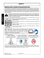 12
12
-
 13
13
-
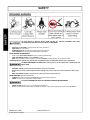 14
14
-
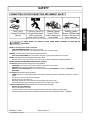 15
15
-
 16
16
-
 17
17
-
 18
18
-
 19
19
-
 20
20
-
 21
21
-
 22
22
-
 23
23
-
 24
24
-
 25
25
-
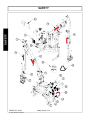 26
26
-
 27
27
-
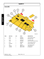 28
28
-
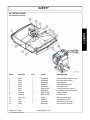 29
29
-
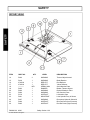 30
30
-
 31
31
-
 32
32
-
 33
33
-
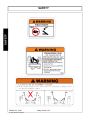 34
34
-
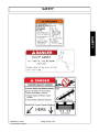 35
35
-
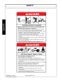 36
36
-
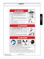 37
37
-
 38
38
-
 39
39
-
 40
40
-
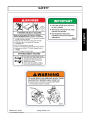 41
41
-
 42
42
-
 43
43
-
 44
44
-
 45
45
-
 46
46
-
 47
47
-
 48
48
-
 49
49
-
 50
50
-
 51
51
-
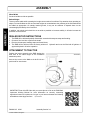 52
52
-
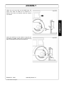 53
53
-
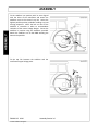 54
54
-
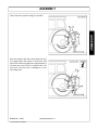 55
55
-
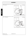 56
56
-
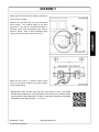 57
57
-
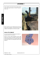 58
58
-
 59
59
-
 60
60
-
 61
61
-
 62
62
-
 63
63
-
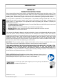 64
64
-
 65
65
-
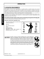 66
66
-
 67
67
-
 68
68
-
 69
69
-
 70
70
-
 71
71
-
 72
72
-
 73
73
-
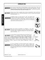 74
74
-
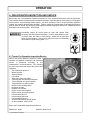 75
75
-
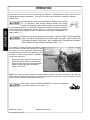 76
76
-
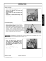 77
77
-
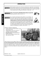 78
78
-
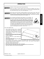 79
79
-
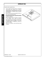 80
80
-
 81
81
-
 82
82
-
 83
83
-
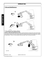 84
84
-
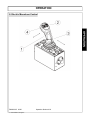 85
85
-
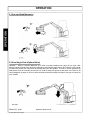 86
86
-
 87
87
-
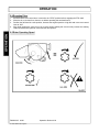 88
88
-
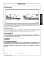 89
89
-
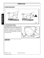 90
90
-
 91
91
-
 92
92
-
 93
93
-
 94
94
-
 95
95
-
 96
96
-
 97
97
-
 98
98
-
 99
99
-
 100
100
-
 101
101
-
 102
102
-
 103
103
-
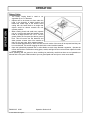 104
104
-
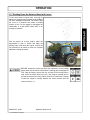 105
105
-
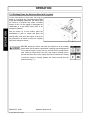 106
106
-
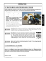 107
107
-
 108
108
-
 109
109
-
 110
110
-
 111
111
-
 112
112
-
 113
113
-
 114
114
-
 115
115
-
 116
116
-
 117
117
-
 118
118
-
 119
119
-
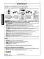 120
120
-
 121
121
-
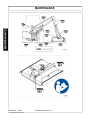 122
122
-
 123
123
-
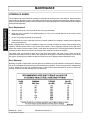 124
124
-
 125
125
-
 126
126
-
 127
127
-
 128
128
-
 129
129
-
 130
130
-
 131
131
-
 132
132
-
 133
133
-
 134
134
-
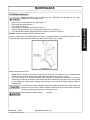 135
135
-
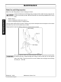 136
136
-
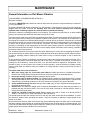 137
137
-
 138
138
-
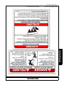 139
139
-
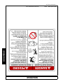 140
140
-
 141
141
-
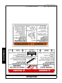 142
142
-
 143
143
-
 144
144
-
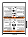 145
145
-
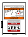 146
146
-
 147
147
-
 148
148
-
 149
149
-
 150
150
-
 151
151
-
 152
152
-
 153
153
-
 154
154
-
 155
155
-
 156
156
-
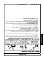 157
157
-
 158
158
-
 159
159
-
 160
160
-
 161
161
-
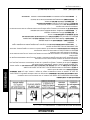 162
162
-
 163
163
-
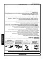 164
164
-
 165
165
-
 166
166
-
 167
167
-
 168
168
-
 169
169
-
 170
170
-
 171
171
-
 172
172
-
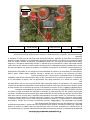 173
173
-
 174
174


Alamo Industrial Rear Mount Boom 165 & 180 Manual de usuario
- Categoría
- Cortadoras de césped
- Tipo
- Manual de usuario
en otros idiomas
Artículos relacionados
-
Alamo Industrial Exten-A-Kut II Rotary Manual de usuario
-
-
-
-
-
-
-
-
-
Otros documentos
-
Bush Hog Multi-Spindle Rotary Cutter El manual del propietario
-
-
-
-
Alamo RHINO 1900 Manual de usuario
-
RHINO BOOM ARM MOWER DB150 Manual de usuario
-
-
 Rhino Mounts RHD62 Manual de usuario
-
ABB M2A Series Instructions Manual
-
 Rigid Industries HKO-186 Manual de usuario

