Snapper L1428E (1695572) El manual del propietario
- Categoría
- Lanzadores de nieve
- Tipo
- El manual del propietario

®
O
A
TO
AL
Large Frame
Snowthrower
1428 Model
Mfg. No. Description
1695572 L1428E, Snowthrower, 130.887280
1736682
Revision 00
Rev. Date 07/2008
TP 191-4968-00-LW-SN

TableofContents
CONTENTS:
Safety Rules & information
General ........................................................... 4
Training .......................................................... 6
Preparation ..................................................... 6
Operation ........................................................ 6
Children .......................................................... 7
Clearing a Clogged Discharge Chute ............. 7
Service, Maintenance and Storage ................ 7
Emissions ....................................................... 7
Decals ............................................................ 8
Safety Icons .................................................... 9
Identification Numbers .................................... 9
Assembly .......................................................... 10
Remove Packing Materials ........................... 11
Raise Handles and Check Cables ................ 11
Install Chute Rotator Control Handle ............ 11
Connect Shift Rod ........................................ 12
Assemble Chute and Rotator ....................... 12
Assemble Split Rod ...................................... 12
Connect Spout Rotator Brake Cable ............ 13
Remove Snowthrower from Crate ................ 13
Secure Cable and Final Checks ................... 14
Check Oil Level and Add Fuel ...................... 14
Read Manual Before Starting Engine ........... 14
Features, Controls, & Operation
Control Locations ......................................... 15
General Operation
Checks Before Each Start-Up ...................... 17
Starting Controls ........................................... 18
Starting the Engine ....................................... 19
Stopping the Engine ..................................... 20
Operating the Snowthrower .......................... 21
Clearing a Clogged Discharge Chute ........... 21
Ground Speed Selector ................................ 22
Engine Speed ............................................... 22
Deflector ....................................................... 22
Scraper Bar & Skid Shoes ............................ 22
Easy-Turn and Traction Drive Lock .............. 23
After Each Use ............................................. 24
Storage ......................................................... 24
Regular Maintenance
Schedule ...................................................... 25
Checking Tire Pressure ................................ 25
Auger Gear Case Lubrication ....................... 25
Lubrication .................................................... 26
Check/Lubricate Free-Hand Linkage .......... 27
Lubricate Auger Shaft Assembly .................. 27
Troubleshooting, Adjustments, & Service
Troubleshooting ............................................ 28
Auger Drive Cable Adjustment ..................... 30
Traction Drive Adjustment ............................ 30
Friction Disk Measurement .................................
31
Easy Turn Cable Adjustment ........................ 32
Belt Adjustment ............................................ 32
Shear Pin Replacement ............................... 33
Belt Guide Adjustment .................................. 33
Belt Replacement ......................................... 34
Specifications ................................................... 37
Parts & Accessories ....................................... 38
A WARNING
You must read, understand and comply with all
safety and operating instructions in this manual
before attempting to set-up and operate your
snowthrower.
Failure to comply with all safety and operating
instructions can result in loss of machine control,
serious personal injury to you and/or bystanders,
and risk of equipment and property damage. The
triangle in the text signifies important cautions or
warnings which must be followed.
A WARNING
Engine exhaust from this product contains chemi-
cals known, in certain quantities, to cause cancer,
birth defects, or other reproductive harm.

tll
g
Congratulations on purchasing a superior-quality piece of lawn
and garden equipment. Our products are designed and manu-
factured to meet or exceed all industry standards for safety.
Power equipment is only as safe as the operator. If it is
misused, or not properly maintained, it can be dangerous!
Remember, you are responsible for your safety and that of
those around you.
Use common sense, and think through what you are doing. If
you are not sure that the task you are about to perform can be
safely done with the equipment you have chosen, ask a
professional: contact your local authorized dealer.
The operator's manual contains important safety information you
need to be aware of BEFORE you operate your unit as well as
DURING operation.
Safe operating techniques, an explanation of the product's features
and controls, and maintenance information is included to help you
get the most out of your equipment investment.
Be sure to completely read the Safety Rules and Information found
on the following pages. Also completely read the Operation section.
DII
Tragic accidents can occur with children. Do not allow
them anywhere near the area of operation. Children
are often attracted to the unit and snowthrowing activ-
ity. Never assume that children will remain where you
last saw them. If there is a risk that children may enter
the area where you are operating the unit, have another
responsible adult watch them.
DO NOT ALLOW CHILDREN TO OPERATE THIS UNIT!
This encourages them to come near the unit in the
future while it is running, and they could be seriously
hurt. They may then approach the unit when you are not
expecting it, and you may run over them.
4

SafetyRules&Infomati(m
M0vJflg
This equipment has many moving parts that can injure you or someone else.
However, if you are standing in the operator's position, and follow all the rules in
this book, the unit is safe to operate.
The auger and impeller have spinning parts that can amputate hands and feet.
Do not allow anyone near the equipment while it is running! DO NOT clear the
discharge chute by hand. If the chute becomes plugged, stop the engine, wait for
all moving parts to stop, and clear the blockage with a clean-out tool or piece of
wood.
To help you, the operator, use this equipment safely, it is equipped with an
operator-present safety system. Do NOT attempt to alter or bypass the system.
See your dealer immediately if the system does not pass all the safety interlock
system tests found in this manual.
Thrown 8C1$
This unit has a spinning auger and impeller. They
pick up and throw snow and ice. Thrown debris
could seriously injure a bystander. ALWAYS direct
the discharge chute away from bystanders and prop-
erty that could be damaged by flying debris. Be sure
to clean up the area to be cleared BEFORE you start.
Do not allow anyone in the area while the unit is run-
ning! If someone does enter the area, shut the unit
off immediately until they leave.
Gasoline is extremely flammable. Its vapors are also
extremely flammable and can travel to distant ignition
sources. Gasoline must only be used as a fuel, not as a
solvent or cleaner. It should never be stored any place
where its vapors can build up or travel to an ignition source
like a pilot light. Fuel belongs in an approved, plastic,
sealed gas can, or in the snowthrower fuel tank with the
cap securely closed. Spilled fuel needs to be cleaned up
immediately.
Proper maintenance is critical to the safety and perfor-
mance of your unit. Be sure to perform the maintenance
procedures listed in this manual, especially periodically test-
ing the safety system.

SafetyRules& Informtm
This machine is capable of amputating hands and feet and throwing objects. Read these safety rules and
follow them closely. Failure to obey these rules could result in loss of control of unit, severe personal injury
or death to you, or bystanders, or damage to property or equipment. The triangle _k in text signifies
important cautions or warnings which must be followed.
TRAINING
1. Read, understand, and follow all instructions on the
machine and in the manuals before operating this
unit. Be thoroughly familiar with the controls and the
proper use of the equipment. Know how to stop the
unit and disengage the controls quickly.
2. Never allow children to operate the equipment.
Never allow adults to operate the equipment without
proper instruction.
3. Keep the area of operation clear of all persons, par-
ticularly small children and pets.
4. Exercise caution to avoid slipping or falling especially
when operating in reverse.
PREPARATION
1. Thoroughly inspect the area where the equipment is
to be used and remove all doormats, sleds, boards,
wires, and other foreign objects.
2. Disengage all clutches before starting engine (motor).
3. Do not operate the equipment without wearing ade-
quate winter outer garments. Wear footwear that will
improve footing on slippery surfaces. Avoid loose fit-
ting clothing that can get caught in moving parts.
4. Handle fuel with care; it is highly flammable.
(a) Use an approved fuel container.
(b) Never add fuel to a running engine or hot engine.
(c) Fill fuel tank outdoors with extreme care. Never
fill fuel tank indoors. Replace fuel cap securely and
wipe up spilled fuel.
(d) Never fill containers inside a vehicle or on a truck
or trailer bed with a plastic liner. Always place con-
tainers on the ground, away from your vehicle, before
filling.
(e) When practical, remove gas-powered equipment
from the truck or trailer and refuel it on the ground. If
this is not possible, then refuel such on a trailer with
a portable container, rather than from a gasoline dis-
penser nozzle.
(f) Keep nozzle in contact with the rim of the fuel tank
or container opening at all times, until refueling is
complete. Do not use a nozzle lock-open device.
(g) Replace gasoline cap securely and wipe up spilled
fuel.
(h) If fuel is spilled on clothing, change clothing imme-
diately.
5. Use extension cords and receptacles as specified
by the manufacturer for all units with electric drive
motors or electric starting motors.
6. Adjust the collector housing height to clear gravel or
crushed rock surfaces.
7. Never attempt to make any adjustments while the
engine (motor) is running (except when specifically
recommended by the manufacturer).
8. Let engine (motor) and machine adjust to outdoor
temperatures before starting to clear snow.
9. Always wear safety glasses or eye shields dur-
ing operation or while performing an adjustment or
repair to protect eye from foreign objects that may be
thrown from the machine.
OPERATION
1. Do not put hands or feet near or under rotating parts.
Keep clear of the discharge opening at all times.
2. Exercise extreme caution when operating on or
crossing gravel drives, walks, or roads. Stay alert for
hidden hazards or traffic.
3. After striking a foreign object, stop the engine (motor),
remove the wire from the spark plug, disconnect
the cord on electric motors, thoroughly inspect the
snowthrower for any damage, and repair the damage
before restarting and operating the snowthrower.
4. If the unit should start to vibrate abnormally, stop the
engine (motor) and check immediately for the cause.
Vibration is generally a warning of trouble.
5. Stop the engine (motor) whenever you leave the
operating position, before unclogging the collector/
impeller housing or discharge guide, and when mak-
ing any repairs, adjustments, or inspections.
6. When cleaning, repairing, or inspecting make cer-
tain the collector/impeller and all moving parts have
stopped. Disconnect the spark plug wire and keep
the wire away from the plug to prevent accidental
starting.
7. Do not run the engine indoors except for starting the
engine or for transporting the snowthrower in or out of
the building. Open the outside doors; exhaust fumes
are dangerous.
8. Exercise extreme caution when operating on slopes.
Do not attempt to clear steep slopes.
9. Never operate the snowthrower without proper
guards plates, or other safety protective devices in
place and working.
10. Never direct the discharge toward people or areas
where property damage can occur. Keep children
and others away.
11. Do not overload the machine capacity by attempting
to clear snow at too fast a rate.
12. Never operate the machine at high transport speeds
on slippery surfaces. Look behind and use care
when operating in reverse.
13. Disengage power to the collector/impeller when
snowthrower is transported or not in use.
14. Use only attachments and accessories approved by
the manufacturer of the snowthrower (such as wheel
weights, counterweights, or cabs).
15. Never operate the snowthrower without good visibility
or light. Always be sure of your footing, and keep a
firm hold on the handles. Walk, never run.
16. Never touch a hot engine or muffler.
17. Never operate the snowthrower near glass enclo-
sures, automobiles, window wells, drop-offs, and the
like without proper adjustment of the discharge angle.
18. Never direct discharge at bystanders or allow anyone
in front of the unit.
19. Never leave a running unit unattended. Always dis-
engage the auger and traction controls, stop engine,
and remove keys.
20. Do not operate the unit while under the influence of
alcohol or drugs.
6

Safety Rules & information
21. Keep in mind the operator is responsible for acci-
dents occurring to other people or property.
22. Data indicates that operators, age 60 years and
above, are involved in a large percentage of power
equipment=related injuries. These operators should
evaluate their ability to operate the unit safely enough
to protect themselves and others from injury.
23. DO NOT wear long scarves or loose clothing that
could become entangled in moving parts.
24. Snow can hide obstacles. Make sure to remove all
obstacles from the area to be cleared.
CHILDREN
Tragic accidents can occur if the operator is not alert to the
presence of children. Children are often attracted to the
unit and the operating activity. Never assume that children
will remain where you last saw them.
1. Keep children out of the area and under the watchful
care of another responsible adult.
2. Be alert and turn unit off if children enter the area.
3. Never allow children to operate the unit.
4. Use extra care when approaching blind corners,
shrubs, trees, or other objects that may obscure
vision.
CLEARING A CLOGGED DISCHARGE
CHUTE
Hand contact with the rotating impeller inside the dis-
charge chute is the most common cause of injury associ-
ated with snowthrowers. Never use your hand to clean
out the discharge chute.
To clear the chute:
1. SHUT OFF THE ENGINE.
2. Wait 10 seconds to be sure the impeller blades have
stopped rotating.
3. Always use a clean out tool, not your hands.
8. Always follow the engine manual instructions for stor-
age preparations before storing the unit for both short
and long term periods.
9. Always follow the engine manual instructions for
proper start-up procedures when returning the unit to
service.
10. Keep nuts and bolts tight and keep equipment in
good condition.
11. Never tamper with safety devices. Check their proper
operation regularly and make necessary repairs if
they are not functioning properly.
12.Components are subject to wear, damage, and dete-
rioration. Frequently check components and replace
with manufacturer's recommended parts, when nec-
essary.
13.Check control operation frequently. Adjust and ser-
vice as required.
14. Use only factory authorized replacement parts when
making repairs.
15.Always comply with factory specifications on all set-
tings and adjustments.
16.Only authorized service locations should be utilized
for major service and repair requirements.
17. Never attempt to make major repairs on this unit
unless you have been properly trained. Improper ser-
vice procedures can result in hazardous operation,
equipment damage and voiding of manufacturer's
warranty.
18.Check shear bolts and other bolts at frequent inter-
vals for proper tightness to be sure the equipment is
in safe working condition.
EMISSIONS
1. Engine exhaust from this product contains chemicals
known, in certain quantities, to cause cancer, birth
defects, or other reproductive harm.
2. If available, look for the relevant Emissions Durability
Period and Air Index information on the engine emis-
sions label.
SERVICE, MAINTENANCE, AND STORAGE
1. Check shear bolts and other bolts at frequent inter-
vals for proper tightness to be sure the equipment is
in safe working condition.
2. Never store the machine with fuel in the fuel tank
inside a building where ignition sources are present
such as hot water and spacer heaters, or clothes dry-
ers. Allow the engine to cool before storing in any
enclosure.
3. Always refer to the operator's manual for impor-
tant details if the snowthrower is to be stored for an
extended period.
4. Maintain or replace safety and instruction labels as
necessary.
5. Run the machine a few minutes after throwing snow
to prevent freeze-up of the collector/impeller.
6. If fuel is spilled, do not attempt to start the engine but
move the machine away from the area of spillage and
avoid creating any source of ignition until fuel vapors
have dissipated.
7. Always observe safe refueling and fuel handling prac-
tices when refueling the unit after transportation or
storage.
IGNITION SYSTEM
1. This spark ignition system complies with Canadian
ICES-002.

Decals
DECALS
This unit has been designed and manufactured to provide
you with the safety and reliability you would expect from an
industry leader in outdoor power equipment.
Although reading this manual and safety instructions it
contains will provide you with the necessary basic knowl-
edge to operate this equipment safely and effectively, we
have placed several safety labels on the unit to remind you
of this important information while you are operating your
unit.
All WARNING, CAUTION, and instructional messages on
your unit should be carefully read and obeyed. Personal
bodily injury can result when these instructions are not fol-
lowed. The information isfor your safety and it is important.
The safety decals below are on your unit.
If any of these decals are lost or damaged, replace them at
once. See your local dealer for replacements.
These labels are easily applied and will act as a constant
visual reminder to you, and others who may use the equip-
ment, to follow the safety instructions necessary for safe,
effective, operation,
NOTE: Engine operation and safety decals are supplied by
the engine manufacturer.
DECALS
Model L1228E Model L1428E
Part No. 1733033 - DANGER / WARNING
Main Dash Decal, North American, w/Easy Turn
Part No. 1733056 - DANGER / WARNING
Main Dash Decal, North American, w/o Easy Turn
.... T................................................[ 1with 30 weight oil every 10 hours of opeTation and
. . before LlSing the unit after storage FailLire to hlbri_3te
ina_causea rf]alfunctionofthe safety s#tem a
Part No. 1733526
Lubrication Decal
Part No. 728183
Important
Over Adjustment
Both Models
Part No. 1733772
Shift Decal
Amputationhazard
_L _J Lontaclv,iththeaugerw,__use
I" Shat off engine bef_e se[_lciag
Part No. 1716532
Auger Danger Decal
Part No. 1733057
Discharge Chute
Danger Decal
Part No. 725432
Belt Stretch &
Adjust
Part No. 1733443
Chute Release

Safety icons
SAFETY iCONS
WARNING: READ OPERATOR'S MANUAL.
Read and understand the Operator's
Manual before using this machine.
DANGER: THROWN OBJECTS.
This machine is capable of throwing
objects and debris. Keep bystanders
away.
WARNING: REMOVE KEY BEFORE
SERVICING.
Remove the key, disconnect spark
plug wire, and consult technical lit-
erature before performing repairs or
maintenance.
WARNING: DISMEMBERMENT.
This machine can amputate limbs.
Keep bystanders and children away
when engine is running.
DANGER:DISMEMBERMENT.
The auger can amputate limbs. Keep
hands and feet away from auger and
rotating parts.
DANGER:DISMEMBERMENT.
The impeller can amputate limbs. Stop
the engine, remove the key, and discon-
nect spark plug wire before clearing the
discharge chute or performing service
work. Keep hands and feet away from
impeller and rotating parts.
Mfg.Ne,:t;,26eXXXX C_'
se,i,I_o.5".'_ xxx _'oo_
Eogi.oRP#",,"x,_}
LpA: _)
Simplicity Mfg. lnc. _/ /\
Port Washington, WI USA 53_7_0997_,
Identification Numbers
When contacting your authorized dealer for replace=
ment parts, service, or information you MUST have
these numbers.
Record your model name/number, manufacturer's iden-
tification numbers, and engine serial numbers in the
space provided for easy access. These numbers can be
found in the locations shown.
NOTE: For location of engine identification numbers,
refer to the engine owner's manual.
Model Description Name/Number
Unit MFG Number Unit SERIAL Number
Mower Deck MFG Number Mower Deck SERIAL Number
Dealer Name Date Purchased
Engine Make _Engine Model
Engine Type/Spec Engine C0de/Serial Number

AssemhJy
YOU WILL NEED:
• Utility knife
• Unleaded fuel
• Tire pressure gauge
• 1/2" deep socket wrench or combination
• 9/16" deep socket wrench or combination
• 7/16" wrench
ITEMS INCLUDED:
a
b h
c
g k
P
d
e
f
q
Figure 1. Parts Bag Contents
a 5/16"FlangeLockNuts,2
b 5/16"JamNut(thin),1
c 3/8" FlangeNuts,2
d 5/16"LockNut,1
e 1/4" LockNuts,2
f ChuteRotatorControl
Handle,1
g 5/16" LockWasher,1
h LargeCarriageBolts,2
j 120VPowerCord,1
k ExtraShearPins,2
m ExtraCotterPins,2
n SmallCarriageBolts,2
p ZipTies,3
q IgnitionKeys,2
(1 pre-attachedtosnowthrower)
Items not shown above:
Operator'sManual
IlhstratedPartsList
ProductRegistrationCard
EngineManual
FreshStart®FuelPreserver
Cartridge
Auger
Engage
Control
Traction
Chute
Rotator
Control
Split Rod
FuelCa
Chute
0il
Dipstick Clean-0ut
Tool
Figure 2. Snowthrower - Assembled
DANGER
Contact with moving parts inside chute will cause
serious injury or death. Shut off engine before
unclogging discharge chute. Use clean=out tool,
not hands!
WARNING
Failure to read and follow the Operator's Manual
and all operating instructions can result in seri-
ous injury or death.
WARNING
Fuel and its vapors are flammable and explosive.
Turn off engine and wait at least 2 minutes before
refueling. Let spilled fuel evaporate before start-
ing engine.
10

AssemhJy
REMOVE PACKAGING MATERIALS
Note: Follow setup instructions in the order pre=
sented.
1. Remove banding from crate. Open carton completely
by cutting each corner from top to bottom as shown
in Figure 3.
,
Open small cardboard box behind snowthrower.
Remove parts bag from inside chute. Remove manu-
al packet. Ensure you have all "Items Included" prior
to assembly.
,
Locate the operator's manual in the manual packet.
Always read and follow the instructions in the opera-
tot's manual. Proper care, performance tips, and
safety information are located in this important docu-
ment.
RAISE HANDLES AND CHECK
CABLES
Note: "Right" and "Left" are from the Operating
Position.
1. Cut orange zip ties that secure control cables to
handle assembly. Be careful not to cut or damage the
control cables.
,
3.
Rotate upper handle assembly (Figure 4A) up.
Slide large carriage bolts (A, Figure 4B) and 5/16"
flange lock nuts (B) into lower holes. DO NOT
TIGHTEN AT THIS TIME.
,
,
,
Remove shipping tape from control levers. Make
sure the "Z" bend ends of the control lever cables are
secured in the holes on the control levers (Figure 5).
Make sure auger engage control and traction control
cables route over the top of cable buttons as shown.
Check that all cables can move freely and are not
kinked.
7. Tighten upper and lower nuts in handle with a 1/2"
wrench or deep socket (Figure 4B).
INSTALL CHUTE ROTATOR
CONTROL HANDLE
1. Install thin jam nut (A, Figure 6) onto chute rotator
rod. Install chute rotator control handle (B) onto chute
rotator rod turning at least 10 full clockwise rotations.
,
Align chute rotator control handle so it is facing for-
ward and use a 9/16" wrench to tighten jam nut (A)
against chute rotator control handle (B).
3. Slide chute rotator control handle to the right.
Figure 3. Snowthrower - Shipping Position
Figure 4A.
Upper Handle Assembly
Figure 5.
Control Lever Cables
Figure 4B.
Upper Handle Assembly
\
Figure 6.
Jam Nut Installation
11

AssemhJy
CONNECT SHIFT ROD
,
Connect shift rod (A, Figure 7) to shift lever (B) and
secure with lock washer (C) and 5/16 lock nut (D).
Tighten lock nut with a 1/2" wrench while preventing
stud (E) from turning with a 7/16" wrench.
ASSEMBLE CHUTE AND ROTATOR
1. Bring chute from pallet to the left side of snowthrow-
er.
2. Slide the chute base (A, Figure 8) onto the auger
housing (B).
3. Slide support tube (C) on the carriage bolts (D).
4. Thread two 3/8" flange nuts (A, Figure 9) onto car-
riage bolts and tighten with a 9/16" wrench.
ASSEMBLE SPLIT ROD
,
,
,
Take end of split rod (A, Figure 10) that is attached to
top back side of chute assembly and align it to right
side of split rod protruding from dash.
Insert two small carriage bolts (B) into square holes
of split rod.
Install 1/4" lock nuts (C) and tighten hardware with a
7/16" wrench.
Figure 7.
Figure 8.
Connect Shift Rod
Chute and Rotator Assembly
Figure 9. Carriage Bolts
Figure 10. Split Rod Assembly
12

AssembJy
CONNECT SPOUT ROTATOR BRAKE
CABLE
1. Slide spout rotator brake cable (A, Figure 11)
between dash and the handle cross bar as shown.
2. Slide rubber dust cover (B) off of plastic fitting as
shown.
3. Place "Z" bend of cable (C) into hole of brake lever
assembly (D).
4. Pull plastic fitting (A, Figue 12) behind bracket (B).
5. Slide chute rotator cable (A, Figure 13) between slot
in bracket and push forward to lock in place.
6. Slide rubber dust cover (B) over plastic fitting.
REMOVE SNOWTHROWER FROM
CRATE
1. Cut straps from between snowthrower and wood pal-
let by wheels and auger.
Figure 11. Spout Rotator Brake Cable
2. Roll snowthrower off crate.
Figure 12. Plastic Fitting
Figure 13. Chute Rotator Cable
13

AssembJy
SECURE CABLE AND FINAL CHECKS
,
To prevent chute deflector cable from contacting tire,
rotate chute all the way to the left and secure with
zip ties (A, Figure 14). Secure cable to left handle (B)
and to support tube (C), and secure speed selector
cable to split rod (D).
2. Reduce tire pressure to 20 PSI. (Tires are over-inflat-
ed for shipping purposes.)
3. Check that clean-out tool is attached to snowthrower.
(See assembled figure.)
Always use a clean=out tool to clear clogged dis=
charge chute. NEVER use your hands.
,
Locate two shear pins and cotter pins in parts
bag. Place hardware in compartment labeled
"Replacement Shear Bolt Storage" located on unit
behind chute.
CHECK OIL LEVEL AND ADD FUEL
Note: Engine is shipped with oil. See Engine Manual
for complete engine oil specifications and mainte=
nance requirements.
1. Remove oil dipstick (A, Figure 15). Check oil level.
Oil level should be between FULL and ADD marks.
Reinstall oil dipstick.
2. Remove fuel cap (B). Following the three-step
instructions on the Fresh Start card, snap the fuel
preserver cartridge into the bottom of the fuel fill cap.
NOTICE: Do not use E22 or E85 fuel.
NOTICE: Do not mix oil with fuel.
DANGER
Fuel and its vapors are flammable and explosive.
Turn off engine and wait at least 2 minutes before
refueling. Let spilled fuel evaporate before start-
ing engine.
3. Add clean, fresh, UNLEADED fuel with a minimum 87
octane. Leave a minimun of one inch of space at top
of tank for fuel expansion. Reinstall fuel cap.
Figure 14. Secure Cables
Figure 15. Check Oil Level
READ MANUAL BEFORE STARTING
ENGINE
Follow procedures and safety instructions in
Operator's and Engine Manuals.
DANGER
Contact with moving parts inside chute will cause
serious injury or death. Shut off engine before
unclogging discharge chute. Use clean=out tool,
not hands!
WARNING
Failure to read and follow the Operator's
Manual and all operating instructions can result
in serious injury or death.
14

Features,Controls,& Operation
CONTROL LOCATIONS
The information below briefly describes the function
of individual controls. Starting, stopping, and driving
require the combined use of several controls applied
in specific sequences. To learn what combination and
sequence of controls to use for various tasks see the
OPERATION section.
IMPORTANT NOTE
Please take a moment and familiarize yourself with the
name, location, and function of these controls so that you
will better understand the safety and operating instruc-
tions provided in this manual,
\
/
Figure 16. Control Locations
15

Features & Controls
1,2.. Speed Selector
Selects forward speeds 1-6 and reverse speeds 1-2. No
neutral position or gate is required, since the traction
drive design automatically provides "neutral" (no forward
or reverse movement), whenever the Drive Control is
released.
_'_ Traction Control / Free Hand TM
Lock
Engages traction drive to wheels when depressed. Also
locks auger control when depressed simultaneously.
Releasing the traction control lever releases the Free
Hand TM auger control lock and stops the drive wheels
and auger.
_ Auger Control
Engages the auger/impeller when depressed. Releasing
the control stops the auger/impeller.
_ Chute Direction Control
Push the lever forward to unlock the rotator control.
Moving the lever to the left will turn the spout to the left
side and moving the lever to the right will rotate the spout
to the right side. Releasing the lever locks the spout in
position.
M Remote Deflector Control
Chute Deflector: Locks chute deflector in desired posi-
tion. Tilting the chute deflector UP provides a higher
stream and greater distance, while tilting the deflector
DOWN provides a lower stream and less distance.
•_O_' Easy Turn TM Control
Easy Turn Control: Engaging the Easy Turn TM lever
releases the left wheel to allow easy turning in tight
areas. Releasing the control automatically engages both
drive wheels for full traction.
Traction Lock Pins: (1100 Series Only) The right trac-
tion wheel can be completely released using the lock-
ing pin (see Figure 9). This allows the unit to be easily
moved with the engine off.
Stop Switch (Optional)
Turn the switch to the ON position to operate the engine,
Turn the switch to the OFF position to stop the engine,
(_) Starter
Electric Start: Depressing the starter button activates
the electric starter. The electric start button operates
on 12+11Models): Pulling the recoil handle cranks the
engine.
J_ Fuel
Fuel tank filler cap (see illustration). Note: The fuel shut
off valve is located under the fuel tank or on the front of
the engine, Close the valve when the snowthrower is
not in use. Open the valve before starting, Leave a min-
imun of one inch of space at top of tank for fuel expan-
sion.
I":-_--Primer Button
When pressed, the primer button provides initial fuel to
help start a cold engine. Normally, pressing the primer
button twice will provide enough fuel to start a cold
engine.
'_ "lliFThrottle Lever (Optional)
Controls engine speed. Move toward the hare icon for
faster engine speed, move toward the turtle icon for
slower engine speed. Move the throttle all the way to
STOP the engine. Set the throttle to FAST (hare icon) for
operation.
Engine Key
The engine key prevents the engine from being started.
The key must be fully inserted into the key slot for the
unit to start, The key can also be used to stop the engine
by pulling the key out of the key slot.
I",1 Choke Knob
The choke knob adjusts the air/fuel mixture, and is used
to help start a cold engine by providing a richer mixture.
Once the engine is warm and running smoothly, the
choke knob should be set to the off position to provide a
normal air/fuel mix.
=D Headlight (Select Models, Not Pictured)
The headlight is on at all times when the engine is run-
ning.
16

OperstJon
GENERAL OPERATION
CHECKS BEFORE EACH START=UP
1. Make sure all safety guards are in place and all nuts,
bolts and clips are secure.
2. Check to make sure that the clean-out tool is
attached to the auger housing. Do not operate the
machine without the clean-out tool properly stored on
the auger housing.
3. Check the engine oil level. See your engine owner's
manual for procedure and specifications.
4. Check to make sure spark plug wire is attached and
spark plug is tightened securely. If necessary, torque
spark plug to 15 ft. Ibs.
5. Check the fuel supply. Leave a minimun of one inch
of space at top of tank for fuel expansion. See your
engine owner's manual for fuel recommendations.
6. Check the scraper bar to make sure it is set at the
desired height. Adjust the skid shoes if necessary.
7. Check the drive control (B, Figure 21), and auger
control (C) for proper operation. If adjustment is
required, see the service section for procedures.
8. Check the chute direction control (D, Figure 21) for
proper operation. The discharge chute should rotate
freely in both directions. See the service section for
adjustment procedures and troubleshooting.
9. Check the chute deflector (E, Figure 21) for proper
operation. The deflector should pivot freely up and
down.
10. Position the chute at the desired starting direction
and set the deflector at the desired angle.
11. Check the speed selector (A, Figure 21) for smooth
operation. The control must move freely into each
speed position gate and remain in position when
released. If the speed selector does not move freely
into all forward and reverse speed positions, contact
your local authorized dealer for assistance.
WARNING
This unit is a "two=stage" snowthrower.
The first stage is the auger, which feeds the snow
back into the impeller housing. The second stage
is the impeller, which throws the snow out the
discharge chute. If bodily contact is made with
the auger or impeller when they are rotating,
severe personal injury will occur.
To avoid injury, keep others and yourself away
from the auger and the discharge chute whenever
the engine is running. Read and follow all of the
safety rules and warnings in this manual.
DANGER
Do not clean out discharge chute with hands.
Contact with moving parts inside chute will
cause serious injury. Use clean out tool provided
with machine. Use the following procedure to
remove objects or clear the chute:
1. Stop the engine. Remove the key.
2. Wait 10 seconds to be sure the auger/impeller
blades have stopped rotating.
3. Always use the clean-out tool. DO NOT use your
hands.
WARNING
For your safety, operation on slopes should be
in an up and down direction only. If it becomes
necessary to move across the face of a slope, use
caution and do not blow snow. Be very careful
when changing direction on a slope.
Proper winter footwear is recommended for the
operator to help prevent slipping. Never attempt
to clean snow from excessively steep slopes. The
maximum slope for any operation is 17.7% (10°).
WARNING
Gasoline is highly flammable and must be hart=
died with care. Never fill the tank when the engine
is hot or running. Always move outdoors to fill
the tank. Keep snowthrower and gasoline away
from open flame or spark.
17

OperstJon
STARTING CONTROLS
See Figure 17 for the following instructions.
Electric Start
A=
Electric Start Button - The Electric Start Button (A)
activates an electric starter mounted to the engine,
eliminating the need to pull the starter handle. The
Electric Start Button operates on 120 Volts AC, which
is provided by connection to the extension cord pro-
vided with units equipped with this feature. Connect
this extension cord ONLY to a properly grounded
3 prong electrical outlet.
Manual Start
B. FuelValve - (Select Models) The fuel valve (B) is
located under the fuel tank. It is used to turn the fuel
supply off for out-of-season storage.
Co Starter Handle - The starter handle (C) connects to a
starter cord to manually start the engine. Pulling start-
er handle rapidly spins the engine crankshaft, cycles
the engine, and generates the spark necessary for
starting the engine.
D. Primer Button - When pressed, the primer button
(D) provides initial fuel to help start a cold engine.
Normally, pressing the primer button twice will pro-
vide enough fuel to start a cold engine.
E. Throttle Lever - (Optional) The throttle lever (E) con-
trols the engine speed. For best overall performance,
the throttle lever should be set to the FAST position.
Use the SLOW position only for warming the engine,
or to help prevent snow/ice freeze-up when shutting
the unit down for the day.
F. Engine Key - The engine key (F) prevents the
engine from being started by unauthorized individu-
als. The key must be fully inserted into the key slot
for the unit to start. The key is also used to stop the
engine by pulling the key out of the key slot.
G. Choke Knob - The choke knob (G) adjusts the air/
fuel mixture, and is used to help start a cold engine
by providing a richer mixture. Once the engine is
warm and running smoothly, the choke knob should
be set to the off position to provide a normal air/fuel
mix.
Ho Stop Switch - (Optional) Switch to the ON position
to operate the engine. Switch to the OFF position to
stop the engine.
Snow Series Max
Snow Series
Figure 17. Engine Controls
18

Operation
STARTING THE ENGINE
WARNING
Rapid retraction of starter cord (kickback) will
pull hand and arm toward engine faster than you
can let go. Broken bones, fractures, bruises or
sprains could result. When starting engine, pull
the starter cord slowly until resistance is felt and
then pull rapidly to avoid kickback.
WARNING
Gasoline and its vapors are extremely flammable
and explosive. Fire or explosion can cause severe
burns or death. When starting the engine, ensure
that spark plug, muffler, fuel cap and air cleaner
are in place and secured. Do not crank engine
with spark plug removed, if engine floods, set
choke (if equipped) to open/run position.
A CAUTION
This engine was shipped from Briggs & Stratton
with oil. Before you start the engine, make sure
you check oil according to the instructions in the
Engine Owner's Manual.
, Check the oil level. See "How To Check/Add Oil"
section in Engine Owner's Manual.
2. Make sure equipment drive controls, if equipped, are
disengaged. See the equipment manual for location
and operation of these controls.
3. Push the stop switch (A, Figure 18), if equipped, to
the ON position.
Or move the throttle control lever (A, Figure 19), if
equipped, to the FAST position. Operate the engine
with the throttle control lever in the FAST position.
WARNING
Engines give off carbon monoxide, an odor-
less, colorless, poison gas. Breathing carbon
monoxide can cause nausea, fainting or death.
When starting the engine, start and run engine
outdoors. Do not run the engine indoors except
for starting the engine or for transporting the
snowthrower in or out of the building. Open the
outside doors; exhaust fumes are dangerous.
WARNING
Unintentional sparking can result in fire or elec-
tric shock.
Unintentional start-up can result in entanglement,
traumatic amputation, or laceration.
• Use a 3-wire extension cord.
First attach extension cord to electric starter
connector and then into a wall receptacle. If
additional extension cord is required, use a 3-
wire.
if the supply cord is damaged, it must be
replaced by the manufacturer or its service
agent or a similarly qualified person in order to
avoid a hazard.
Figure 18. Engine Start/Stop
4. Turn the fuel shut-off valve (B, Figure 19), if
equipped, to the ON position.
5. Push in the safety key (C).
6. Turn the choke control knob (D) to the choke posi-
tion.
NOTE: Do not use the choke to start a warm engine.
7. Push the primer button (E) two times.
NOTE: Do not use the primer to start a warm engine.
8. Rewind Start: Firmly hold the starter cord handle
(F). Pull the starter cord slowly until resistance is felt,
then pull rapidly.
NOTE: If the engine does not start after three
attempts, see the "Troubleshooting" section in the
Engine Owner's Manual.
19

(Jperstion
NOTE: If the engine does not start after three
attempts, see the "Troubleshooting" section in the
Engine Owner's Manual.
11. Allow the engine to warm up for several minutes.
Then, slowly move the choke control knob to the run
position.
Figure 19. Engine Start/Stop
, Electric Start: First connect the extension cord to
the power cord receptacle (A, Figure 20) and then
into a wall receptacle. If an additional extension cord
is required, make sure it is a 3-wire.
A WARNING
If the extension cord is damaged, it must be
replaced by the manufacturer or its service agent
or a similarly qualified person in order to avoid a
hazard.
CAUTION
To extend the life of the starter, use short starting
cycles (five seconds maximum). Wait one minute
between starting cycles.
10. Electric Start: Depress the push button (B). After
you start the engine, first disconnect the exten-
sion cord from the wall receptacle and then from the
power cord receptacle (A).
Figure 20. Engine Start - Electric
STOPPING THE ENGINE
WARNING
Gasoline and its vapors are extremely flammable
and explosive.Fire or explosion can cause severe
burns or death. Do not choke the carburetor to
stop the engine.
,
,
,
Move the stop switch (A, Figure 18), if equipped, to
the STOP position.
Or move the throttle control lever (A, Figure 19), if
equipped, to SLOW and then to the STOP position.
Remove the safety key (C). Keep the safety key out
of reach of children.
After the engine stops, turn the fuel shut-off valve (B)
to the CLOSED position.
2O

OperstJon
OPERATING THE SNOWTHROWER
1. Rotate the discharge chute to the desired direction.
2. Set the speed selector to the desired forward speed.
3. Fully press and hold the auger engage control (C,
Figure 21) on the right-hand grip to begin auger rota-
tion. Releasing the auger engage control will disen-
gage the auger--unless the Free=Hand TM Control
has been activated (See Step 5 below).
4. Fully press and hold the traction & Free-Hand TM
Control lever (B, Figure 21) on the left-hand grip
to engage the traction drive and begin moving the
snowthrower. To disengage the traction drive, com-
pletely release the lever.
.
When BOTH levers are depressed, the Free-Hand TM
Control is activated. This allows Auger Engage
Control to be released -- YET AUGER ROTATION
WILL CONTINUE -- until the Free=Hand TM Control
is released.
6. Select forward or reverse speeds as needed using
the Speed Selector (A, Figure 21). Release both con-
trol levers before changing drive speeds.
A WARNING
When BOTH levers are depressed, the Free=
Hand TM Control is activated. This allows Auger
Engage Control to be released m YET AUGER
ROTATION WILL CONTINUE m until the Free=
Hand TM Control is released.
CLEARING A CLOGGED DISCHARGE
CHUTE
IMPORTANT NOTE
Hand contact with the rotating auger/impeller
inside the discharge chute is the most common
cause of injury associated with snowthrowers.
DO NOT use your hand to clean out the discharge
chute.
To clear the chute:
1. Stop the engine. Remove the key.
2. Wait 10 seconds to be sure the auger/impeller blades
have stopped rotating.
3. Always use the clean-out tool. DO NOT use your
hands.
Figure 21. Controls (From Operator's Position)
21

OperstJon
GROUND SPEED SELECTOR
Use the speed selector (A, Figure 21) to control the drive
speed of the snowthrower. There are six forward speeds
and two reverse speeds.
Use the lower speeds to blow deep or wet snow. Use the
higher speeds to blow light snow or to drive the snow-
thrower without blowing snow.
To change speeds, release the auger control lever (B,
Figure 21), then move the speed selector to the desired
setting. Fully depress the control levers to resume.
ENGINE SPEED
Always run the snowthrower at full throttle.
DEFLECTOR
The distance of the discharged snow is mainly controlled
by the position of the deflector. (Engine speed also
affects distance of discharge.) The more the deflector is
tilted UP, the farther snow will be thrown.
1. Push the remote deflector control (E, Figure 21) to
the left to UNLOCK the control. Sliding the control
forward will put the deflector to the maximum throw-
ing position (A, Figure 22). Sliding the control back-
wards to decrease the throwing distance.
2. Release the control to LOCK in place when the
desired angle has been chosen.
SCRAPER BAR & SKiD SHOES
On smooth surfaces such as concrete or asphalt, the
scraper bar (A, Figure 23) should scrape the surface. On
surfaces such as gravel, the scraper bar should be high
enough so that it will not pick up gravel or debris.
The height of the scraper bar (A) is controlled by raising
or lowering the skid shoes (B).
1. To raise the scraper bar height, rest the scraper bar
(A) on a strip of wood equal in thickness to the desired
height.
2. Make sure the scraper bar is parallel to the ground
surface.
3. Loosen the skid shoe nuts (C) and let the skid shoes
(B) drop to the surface.
4. Tighten the nuts (C), making sure the skid shoes are
adjusted equally and are parallel to the surface.
5. To lower the height of the scraper bar, raise the skid
shoes. Or adjust scraper bar by loosening the attach-
ment bolts and sliding scraper bar down.
6. If the scraper bar becomes worn, it can be replaced
by removing the hardware attaching it to the
snowthrower.
Figure 22.
Figure 23.
Remote Deflector Control
1
Skid Shoe Adjustment
22

Operation
FULL TRACTION
Easy Turn TM
Lever
Released
Both Wheels Drive
EASY TURN TM TRACTION
Engaged
Left Wheel Freewheels,
Y
Turn TM
Lever
Figure 24. Easy Turn Control
Right Wheel Drives
EASY TURN TM FREEWHEELING AND
TRACTION DRIVE LOCK
While Clearing Snow:
For easy turning when using the snowthrower, squeeze
the Easy Turn TM lever (Figure 24). Engaging the
Easy Turn TM lever releases the left traction wheel but
allows the right wheel to continue driving (Figure 24).
Releasing the Easy Turn TMlever automatically engages
both drive wheels for full traction.
NOTE: The Easy Turn TM lever will be more difficult to
activate under a heavy load. Activate the lever before
beginning a turn.
Figure 25. Traction Drive Lock
When Pushing the Snowthrower:
(Units without Easy Turn)
For easy turning when pushing the snowthrower, dis-
engage the right wheel using the traction lock pin (See
Figure 25).
1. Turn the unit off, remove the engine key, and discon-
nect the spark plug wire.
23

OperstJon
AFTER EACH USE
Normal use of the snowthrower may result in a build-up
of packed snow in and around the starter cord housing
and around engine controls. Heat from the engine will
usually prevent the snow from freezing solid while the
unit is running, but after the engine is shut down, some
snow may continue melting from engine heat, and later
freeze around some moving parts as the unit cools.
After each period of use, follow these steps to prevent
freeze-up caused by ice formation in and around the
engine controls and external parts.
1. Before shutting off the engine, pull the starter rope
out 2 - 3 times, and allow it to rewind slowly. This will
help clear packed snow from the starter cord area.
Allow the engine to run for several minutes.
2. Stop the engine by moving the throttle lever (See
Figure 17) down, turn the stop switch to the off posi-
tion or by pulling out the engine key.
, Brush snow and ice from the snowthrower. Be sure
to clear engine and snowthrower controls, discharge
chute, and chute rod gears, clutch cable areas, and
anywhere else snow has accumulated.
4. Always remove the engine key and store in a safe
place to prevent unauthorized use.
5. If the snowthrower is kept in a cold shelter, fill the
fuel tank to prevent condensation. Do not store near
sparks or flame.
NOTE: The Engine Owner's Manual contains further
information on preventing ice formation and freeze=up.
STORAGE
WARNING
Never store the unit (with fuel) in an enclosed,
poorly ventilated structure. Fuel vapors can trav-
el to an ignition source (such as a furnace, water
heater, etc.) and cause an explosion.
Fuel vapor is also toxic to humans and animals.
Before you store your unit for the off-season, read the
Maintenance and Storage instructions in the Safety
Rules section, then perform the following steps:
Disengage the PTO, set the parking brake, and
remove the key.
Perform engine maintenance and storage measures
listed in the engine owner's manual. This includes
draining the fuel system, or adding stabilizer to the
fuel (do not store a fueled unit in an enclosed struc-
ture - see Warning).
Before starting the unit after it has been stored:
• Check all fluid levels. Check all maintenance items.
• Perform all recommended checks and procedures
found in the engine owner's manual.
• Allow the engine to warm up for several minutes
before use.
WARNING
Never store the unit, with gasoline in engine
or fuel tank, in a heated shelter or in enclosed,
poorly ventilated enclosures. Gasoline fumes may
reach an open flame, spark or pilot light (such as
a furnace, water heater, clothes dryer, etc.) and
cause an explosion.
Handle gasoline carefully. It is highly flammable
and careless use could result in serious fire dam-
age to your person or property.
Drain fuel into an approved container outdoors
away from open flame or sparks.
24

MAINTENANCE SCHEDULE
Maintenance Required
Check/Lubricate Free-Hand Linkage.
Lubricate snowthrower.
Check tire pressure.
Change engine oil.*+
Clean or replace spark plug.+
Check drive linkage/belt tension.
Lubricate Axle Shafts.
Check auger gear case lubrication.**
Lubricate Auger Shaft.***
* Changeoriginal oil after two hoursof operation.
** Checkoil level each fall and spring.
+ See your engine Owner's Manual.
***Lubricate each fall and spring.
RegularMaintenance
Frequency Notes
10 Hours 10W Oil
10 Hours 10W Oil and Grease
Monthly 20 psi (1,38 bar)
50 Hours See Engine Manual
Yearly See Engine Manual
4-6 Hours See Page 28
Yearly Lithium Grease
25 Hours Benalene Grease
10 Hours Lithium Grease
CHECKING TIRE PRESSURE
The air pressure in each tire (Figure 26) should be equal
for both tires for best performance. Be sure to keep caps
on valves to prevent entry of debris into the valve stem
when tires are filled.
Size PSi
15 x 5.0-6 20
16 x 4.8-8 14
bar
1,38
,96
Figure 26. Checking Tire Pressure
AUGER GEAR CASE LUBRICATION
1. Place the snowthrower on a level surface.
2. Remove the pipe plug (A, Figure 27).
3. Check the lubricant level. It should be level with the
lower edge of the plug opening. If not, add Benalene
grease.
4. Re-install pipe plug, and tighten securely.
Figure 27. Auger Lubrication
25

ReguJapMaintenance
LUBRICATION
iMPORTANT NOTE
it is very important that grease fittings on the
auger shaft are lubricated regularly, if auger rusts
to shaft, damage to worm gear may occur if shear
pins do not break.
To prevent wheels rusting to axles, it is also nec=
essary to remove the wheeJs and grease the axles
regularly.
Remove wheels and grease axles once each year.
Apply 5W=30 synthetic motor oil to the friction disk drive
hex shaft (A, Figure 29).
Apply medium weight (10W) oil to points shown (See
Figures 28-31).
Generally, all moving metal parts should be oiled where
contact is made with other parts. Keep oil and grease off
belts, pulley grooves, drive disc, and friction disc.
LUBRICATION NOTES:
Grease locations indicated by grease gun symbol.
Use grease fittings when present. Disassemble
parts to apply grease to moving parts when grease
fittings are not installed.
Oil locations indicated by oil can symbol. Do not
allow oil to drip onto traction drive or friction disc.
Do not lubricate remote deflector control.
Figure 29. Drive Lubrication
\
Figure 30. Lubricate Axles and Control Levers
I
Figure 31. Deflector Hinge
Figure 28. Lubricate Spout Rotator
26

ReguJapMaintenance
CHECK / LUBRICATE FREE-HAND
LINKAGE
Check the function of the Free=Hand controls. The con-
trois should function as described in the CONTROLS
section. It is critical for the safe operation of the unit
that the controls disengage when released.
Lubricate as shown in Figure 32.
IMPORTANT NOTE
If the controls do not function properly, lubricate them. If
lubrication does not rectify the problem, see your autho=
rized service dealer. Under no circumstances should the
unit be used if the controls are not functioning properly.
IMPORTANT NOTE
It is very important that grease fittings on the auger shaft
are lubricated regularly. If auger rusts to the shaft, dam-
age to worm gear may occur if shear pins do not break.
LUBRICATE AUGER SHAFT
ASSEMBLY
1. Remove cotter pin (C, Figure 33) and shear pin (B).
2. Use a grease gun and squirt several shots of grease
into grease fitting (A).
3. Rotate auger assembly (D) several times to distribute
the grease evenly. Repeat Step 2.
4. Reinstall shear pin (B) and cotter pin (C).
5. Repeat procedure for other side.
Figure 32. Lubricate Free=Hand Control
Figure 33. Lubricate Auger Shaft Assembly
27

Troubleshooting, , & Service
TROUBLESHOOTING
This section provides troubleshooting and service instruc-
tions. Locate the problem and check the possible cause/
remedy in the order listed.
Also, refer to the Engine Owner's Manual for additional
information.
For problems not covered here, contact your authorized
service dealer.
WARNING
Before performing any adjustment or service to
snowthrower, stop the engine and wait for mov=
ing parts to stop. Remove the key. To prevent
accidental starting, disconnect the spark plug
wire and fasten away from the plug.
Problem Remedy
Engine fails to start. Push key in to the ON position.
Engine starts hard or runs poorly.
Scraper bar does not clean hard
surface.
Auger does not rotate.
Possible Cause
Key is OFF.
Failure to prime cold engine
Fuel valve is in CLOSED position.
Out of fuel.
Choke OFF - cold engine.
Engine flooded.
No spark.
Water in fuel, or old fuel.
Fuel mixture too rich.
Carburetor adjusted incorrectly.
Spark plug faulty, fouled, or gapped
improperly.
Fuel cap vent is blocked.
Skid shoes improperly adjusted.
Skid shoes improperly adjusted.
Auger control not engaged.
Foreign matter blocking auger.
Press primer button twice and
restart.
Turn valve to OPEN position.
Fill fuel tank.
Turn choke to ON, set throttle to
FAST.
Turn choke to OFF; try starting.
Check gap. Gap plug, clean elec-
trode, or replace plug as necessary.
Drain tank. (Dispose of fuel at an
authorized hazardous waste facility.)
Fill with fresh fuel.
Move choke to OFF position.
See your authorized service dealer
for adjustments.
Clean and gap, or replace.
Clear vent.
RAISE skid shoes (this lowers the
scraper bar).
LOWER skid shoes (this raises the
scraper bar.)
Engage auger control.
STOP engine and REMOVE the
key. DISCONNECT the spark plug
wire. Clear auger using clean-
out tool. See warning in SAFETY
RULES.
Auger drive clutch cable slack. Tighten to remove slack. See auger
clutch cable adjustment.
Auger drive belt slipping. Check auger drive belt adjustment.
Broken belt. Replace belt.
Shear pin broken. Replace shear pin.
28

Problem
Auger rotates, but snow is not=
thrown far enough.
Possible Cause
Chute deflector too low.
Poor traction.
Auger does not stop when
auger lever is released.
Snowthrower does not stop
when drive lever is released.
Discharge control is difficult to
operate.
Snowthrower veers to one
side.
Excessive vibration.
Engine speed too slow.
Ground speed too fast.
Snowthrower discharge chute
clogged.
Auger belt loose or worn.
Tires slipping.
Free=Hand TM control is ACTIVE.
Auger clutch rod too tight or bent.
Auger drive belt out of adjustment.
Adjust auger belt guide.Auger belt guide out of adjust-
ment.
Traction drive clutch rod bent or
too tight.
Traction drive clutch rod loose.
Drive belt loose, broken, or
stretched.
Drive roller chain damaged.
Traction lock pins in free-Wheeling
position (OUTER hole).
Friction disc worn.
Gearing needs lubrication
Worm gear not adjusted properly.
Control rod gears misaligned.
Tire pressure not equal.
One wheel is set in free-wheeling
mode. (Traction Lock Pin is in the
OUTER hole).
Loose parts or damaged auger.
Remedy
Adjust deflector as necessary,
Set speed to full throttle.
Use slower speed selector setting.
STOP engine and REMOVE the key.
DISCONNECT the spark plug wire.
Clear auger using clean-out tool, See
warning in SAFETY RULES.
Check auger drive belt adjustment
Check tire pressure and tread,
Release both auger engage control
AND Free-Hand TM control to stop
auger.
Loosen or straighten clutch rod.
Adjust auger belt.
Loosen rod to remove slack or replace.
See adjustment procedure.
Tighten to remove slack. See adjust-
ment procedure.
Replace drive belt.
Replace chain.
Change traction lock pins to INNER
hole to engage traction drive.
Replace disc (see your authorized
service dealer).
Oil or grease as required.
Adjust worm gear. See adjustment pro-
cedure.
Adjust gear bracket. See adjustment
procedure.
Check tire pressure.
Make certain the left traction lock pin is
in the INNER holes (to engage traction
drive).
STOP engine and REMOVE the key.
DISCONNECT the spark plug wire.
Tighten all hardware. Replace auger if
necessary. If vibration continues, see
your dealer.
Drive fails to move snowthrow= Traction drive out of adjustment. Readjust drive, or shift speed selector
er at slow speeds, setting up one speed faster.
29

Adjustments
AUGER DRIVE ADJUSTMENT
WARNING
Do not over=tighten, as this may lift the lever and
cause auger drive to be engaged without depress=
ing the Auger Control.
1. Check that the auger cable (A, Figure 34) is on top of
cable button (B) as show in Figure 34.
2. With the drive lever released, the hook (B, Figure 35)
should barely touch the lever (C) without raising it.
There can be a maximum 1/32" clearance as shown.
3. To adjust, loosen nut (D) by holding the adjusting
flats (A) and turning nut (D). Turn adjustment flats
and hold screw. The adjustment screw is a phillips
screw and the head can be held or turned by insert-
ing a screwdriver through the spring (F).
,
5.
Hold adjusting flats (A) and tighten nut (D).
Start unit and check auger. Auger must not be
engaged unless auger control is depressed.
6. With engine running, fully depress auger control, the
auger should engage and run normally.
7. Release auger control. Auger must stop within 5
seconds.
,
,
If auger does not operate properly, stop engine and
recheck drive linkage adjustments.
If auger linkage is properly adjusted, auger drive
belt tension may require adjustment. See "Belt
Adjustment" in this section of the manual.
TRACTION DRIVE CABLE
ADJUSTMENT
initial Adjustment
WARNING
Do not over=tighten, as this may cause traction
drive to engage without depressing the traction
drive control (arm must remain in down position).
Verify that the cables are not over=tightened: With
speed selector in position 1 and traction drive
control fully released, push snowthrower forward.
The unit should move forward freely.
If unit does not move forward freely, the cable has
been over=tightened. To remedy, loosen tension
on clutch cable slightly, and recheck.
Figure 34. Auger Cable Button
Figure 35. Auger Drive Adjustment
1. With the drive lever released there should be no
slack in cable when moved slightly from side to side.
2. To adjust tension on the cable slide the cable boot
(A, Figure 36) off the cable adjustment bracket (D).
3. Remove the "Z" hook (C) from the cable adjustment
bracket (D) to a different adjustment hole. The cable
should have no slack. The cable should have no ten-
sion or load.
NOTE: If the cable is too slack the unit will not drive. If
the cable is too tight the drive will be engaged without
pushing the handles down.
4. Slide the cable boot (A) over the cable adjustment
bracket.
30

Adjustments
Figure 36. Traction Drive Cable Adjustment
Run=in Adjustment
1. After 5 hours of use, check for proper adjustment.
Readjust clutch cable if necessary by increasing ten-
sion on cable. A small amount of arm movement is
permissible if unit passes operating checks described
in the Warning above.
WARNING
Gasoline is highly flammable and must be han-
dled with care. Drain gasoline outdoors. Never
drain the tank when the engine is still hot from
recent operation. Do not allow open flame, smok-
ing or matches in the area. Avoid over=filling and
wipe up any spills.
FRiCTiON DISC MEASUREMENT
1. Remove the gas from the gas tank.
2. Disconnect the spark plug wire.
Figure 37. Friction Disc Measurement
Figure 38. Speed Selector Linkage
,
10.
11.
12.
\
\
4-5/16"
(10.95cm)
3. Stand snowthrower on the front of the auger housing
(C, Figure 44). 13.
4. Loosen the capscrews (A, Figure 44) on each side of
the bottom panel (B). 14.
5. Remove the bottom panel (B).
6. Position the shift speed lever in the lowest forward
speed.
7. Note the position of the friction disc (A, Figure 37).
The correct distance from the right side of the friction
wheel to the outside of the frame is 4-5/16" (10.95
cm). If the friction disc is not in the correct position,
adjust as follows.
8. Position the shift speed lever in the lowest forward
speed.
Loosen the jam nut (B, Figure 38).
Remove Iocknut (D).
Move the friction disc (A, Figure 37) to the correct
distance, 4-5/16" (10.95 cm).
Turn the ball joint (C, Figure 38) until it is aligned
with the mounting hole in the shifter rod (E). When
aligned, attach the ball joint (C) to the shifter rod (E)
and tighten the jam nut (B).
Check that the snowthrower operates in R1. If not
follow procedures 1-11 and readjust as necessary.
Install the bottom panel (B, Figure 44) and tighten the
capscrews (A).
31

Adjustments
EASY TURN TM CABLE ADJUSTMENT
If the Easy Turn TM cable has stretched, the gears will not
disengage when the control lever is activated. Adjust the
cable using the following procedure.
1. Turn the engine off and disconnect the spark plug
wire.
2. Loosen the jam nut (B, Figure 39).
3. Turn the adjustment nut (A) to lengthen or shorten
the cable. The cable should be tightened just until all
slack is removed from the lever, however it must not
engage the Easy Turn TM release without depressing
the control lever.
4. Tighten the jam nut.
BELT ADJUSTMENT
Auger Drive Belt
If your snowthrower will not discharge snow, check the
control cable adjustment. If it is correct, then check
the condition of the auger drive belt. If it is damaged or
loose, replace it. See "Belt Replacement" in this section
of the manual.
,
2.
,
Disconnect spark plug wire.
Remove screw (B, Figure 40) from belt cover (A).
Remove belt cover (A).
Loosen nut (D, Figure 39) on auger idler pulley (B)
and move auger idler pulley towards belt about 1/8
inch (3 mm).
4. Tighten nut (D).
5. Engage auger drive clutch. Check tension on belt
(opposite idler pulley). Belt should deflect about 1/2
inch (12.5 mm) with moderate pressure, see Figure
25). You may have to move the idler pulley more
than once to obtain the correct tension.
6. Reinstall belt cover (A, Figure 40) securing with
screws (B).
7. Whenever belts are adjusted or replaced, the cables
will need to be adjusted. See "Cable Adjustment" in
this section of the manual.
8. Attach the spark plug wire.
Traction Drive Belt
The traction drive belt has constant spring pressure and
does not require an adjustment. If the traction drive belt
is slipping,replace the belt. See "Belt Replacement" in
this section of the manual.
Figure 39. Cable Adjustment
Figure 40. Belt Cover
__'_k_ coj/ ,,,.-- ,,_ 1/2"(12.5mm)
eflection
Figure 41. Auger Belt Deflection
32

Adjustments & Service
SHEAR PIN REPLACEMENT
WARNING
Do not go near the discharge chute or auger
when the engine is running. Do not run the engine
with any cover or guard removed.
Under most circumstances, if the auger strikes an object
which could cause damage to the unit, the shear pin will
break. (This protects the gear box and other parts from
damage.)
The shear pins are located on the auger shaft as shown
in Figure 42. To replace the shear pins, tap out the bro-
ken pin with a pin punch, and install a new shear pin and
cotter pin. Do NOT replace shear pins with anything
other than the correct grade replacement shear pin.
(Use of bolts, screws or a harder shear pin will lead to
damaged equipment.)
Replacement Shear Pins, Part Number 1668344 are
available at www.sears.com or by calling 1=800=4=MY=
HOME,
BELT GUIDE ADJUSTMENT
1. Disconnect spark plug wire.
2. Remove screw (B, Figure 40) from belt cover (A).
Remove belt cover (A).
3. Engage auger drive and measure the distance
between the belt guide (B, Figure 43) and the belt
(D). The distance should be 1/8 inch (3.18 mm).
4. If adjustment is necessary, loosen belt guide cap-
screw (C). Move belt guide (B) to correct position.
Tighten capscrew (C).
6. Reinstall belt cover (A, Figure 40) securing with
screws (B).
7. Reconnect spark plug wire.
I
Figure 42.
!
Shear Pins
18 mm)
Figure 43. Belt Guide
33

SGPvic6
BELT REPLACEMENT
Auger Drive Belt
The drive belts are of special construction and must be
replaced with original factory replacement belts avail-
able from your nearest authorized service center. Some
steps require the assistance of a second person. If the
auger drive belt is damaged, the snow thrower will not
discharge snow. Replace the damaged belt as follows.
Disconnect the spark plug wire.
.
2.
Loosen the capscrews (A, Figure 44) on each side of
the bottom panel (B).
3. Remove the bottom panel (B).
4. Loosen screw (B, Figure 40) from belt cover (A).
Remove belt cover (A).
.
.
Loosen the belt guide (B, Figure 45). Pull the belt
guide away from the auger drive pulley (C).
Pull the auger idler pulley (K) away from the auger
drive belt (D) and slip the belt off of the idler.
7. Remove the auger drive belt (D) from the engine pul-
ley. To remove the auger drive belt (D), the auger
drive pulley (C) may have to be partially rotated.
8. Index or point the spout rotator to the center of the
machine so the rotator control is in the center of the
dash panel.
.
Using a 7/16 wrench, remove the 2 carriage bolts (A,
Figure 45) and 2 lock nuts (B) from chute rod (C).
10. Remove the upper four capscrews (A, Figure 47) that
hold together the auger housing (C) and the frame
(D). Loosen the lower two capscrews (B). The auger
housing (C) and the frame (D) can now be split apart
for removal of the belt.
11. Remove the old auger drive belt (D, Figure 46) from
the impeller pulley. Replace the auger drive belt with
an original factory replacement belt available from an
authorized service center.
12. Install the new auger drive belt (D) onto the impeller
pulley.
Figure 44. Bottom Cover
Figure 45. Split Rod Assembly
Figure 46. Pulleys and Belts
34

Adjustments & Service
NOTE: To assemble the auger housing to the frame,
have someone hold the auger clutch lever in the
ENGAGED position. This will move the idler arm and pul-
ley enough to allow the auger drive pulley to move back
into position.
14.Assemble the auger housing (C, Figure 47) to the
frame with the four upper capscrews (A) that were
removed in Step 10. Tighten the 2 lower capscrews
(B).
15. Index or point the spout rotator to the center of the
machine so the rotator control is in the center of the
dash panel.
16. Install small carriage bolts (A, Figure 46) and cap-
screws (B) and tighten with 7/16 wrench.
19. Install the auger drive belt (D, Figure 46) onto the
impeller pulley (H).
20. Slip the auger drive belt (D) under the auger idler pul-
ley (K).
21. Adjust the auger drive belt. See "How To Adjust The
Auger Drive Belt" in the Service section.
22. Adjust the belt guide. See "How To Adjust The Belt
Guide" in the Service section.
23. Install the belt cover (A, Figure 40). Tighten screws
(B).
24. Check the adjustment of the cables. See "How To
Check And Adjust The Cables" in the Adjustment
section.
25. Install the bottom panel (B, Figure 44).
26. Tighten the capscrews (A) on each side of the bottom
panel (B).
27. Connect the spark plug wire.
Figure 47. Frame and Axle Housing
35

SGPvic6
Traction Drive Belt
If the snow thrower will not move forward, check the trac=
tion drive belt for wear or damage. If the traction drive
belt is worn or damaged, replace the belt as follows.
1. Disconnect the spark plug wire.
2. Remove the auger drive belt. See "How To Remove
The Auger Drive Belt" in the Service section.
3. Remove the E-ring (J, Figure 46) from one end of
the swing plate axle rod (I).
4. Remove the swing plate axle rod (I) to allow the
swing plate (A, Figure 48) to pivot forward.
5. Remove the traction drive spring (E, Figure 46).
,
Remove the old traction drive belt (A) from the trac-
tion drive pulley (G) and from the traction drive pulley
(F). Replace the traction drive belt (A) with an origi-
nal factory replacement belt available from an autho-
rized dealer.
7. Install the new traction drive belt (A, Figure 46) onto
the traction drive pulley (G) and onto traction drive
engine (F).
8. Make sure the traction drive idler pulley (L) is prop-
erly aligned with the traction drive belt (A).
9. Attach the traction drive spring (E).
10. Install the swing plate axle rod (I) and secure with the
E-ring (J) removed earlier.
11.The bottom of the swing plate (A, Figure 48) must
be positioned between the alignment tabs (B). Make
sure the swing plate is properly secured.
NOTE: If the drive will not engage after the traction drive
belt has been replaced, then check to make sure that the
swing plate is positioned between the alignment tabs.
12. Install and adjust the auger drive belt. See "Belt
Replacement" in this section of the manual.
13.Adjust the belt guide. See "Belt Adjustment" in this
section of the manual.
14. Install the bottom panel (B, Figure 44).
15.Tighten the capscrews (A) on each side of the bottom
panel (B).
16. Reinstall belt cover (A, Figure 40) and secure with
screws (B).
17. Check the adjustment of the cables. See "Cable
Adjustment" in this section of the manual.
18. Connect the spark plug wire.
Figure 48. Traction Belt Change
36

NOTE: Specifications are correct at time of printing and are subject to change without notice.
* The gross power rating for individual gas engine models is labeled in accordance with SAE (Society of Automotive
Engineers) code J1940 (Small Engine Power & Torque Rating Procedure), and rating performance has been
obtained and corrected in accordance with SAE J1995 (Revision 2002-05). Torque values are derived at 3060 RPM;
horsepower values are derived at 3600 RPM. Actual gross engine power will be lower and is affected by, among
other things, ambient operating conditions and engine-to-engine variability. Given both the wide array of products
on which engines are placed and the variety of environmental issues applicable to operating the equipment, the gas
engine will not develop the rated gross power when used in a given piece of power equipment (actual "on-site" or net
power). This difference is due to a variety of factors including, but not limited to, accessories (air cleaner, exhaust,
charging, cooling, carburetor, fuel pump, etc.), application limitations, ambient operating conditions (temperature,
humidity, altitude), and engine-to-engine variability. Due to manufacturing and capacity limitations, Briggs & Stratton
may substitute an engine of higher rated power for this Series engine.
ENGINE"
1450 Series Briggs & Stratton
Make Briggs & Stratton
Model Snow Series Max, M20H
Gross Torque* 14.50 ft-lbs (19.7 Nm) @ 3060 rpm
Displacement 18.6 cu. in (305 cc)
Oil Capacity 28 oz. (,84 I)
CHASSIS:
Wheels
- 1428, Tire Size: 15 x 5
Inflation Pressure: 20 psi (1,37 bar)
Spout Rotation 200 Degrees
Impeller 12 in. (30 cm) 3 Blade Ribbon Flighted Steel
Auger Opening Height 21 in. (53 cm)
Drive System Friction Disc, 6 Forward Speeds, 2 Reverse
DIMENSIONS:
Effective Clearing Width
- 1428 28 in. (71 cm)
Length
- 1428 57.5 in. (146 cm)
Height
- 1428 44.1 in. (112 cm)
Weight
- 1428 255 lbs (116 kg)
37

& Accessories
REPLACEMENT PARTS
Replacement parts are available from your authorized
dealer. Always use genuine Snapper Service Parts.
MAINTENANCE ITEMS
Many convenient and helpful service and maintenance
items are available from you authorized dealer. Some of
these items include:
Engine Oil
Touch-Up Paint
Grease Gun Kit
8 oz. Grease Tube
Tire Sealant
Degrimer/Degreaser
Gas Stabilizer
TECHNICAL MANUALS
Additional copies of this manual are available, as well as
fully illustrated parts lists,
Technical manuals can be downloaded from www.snap-
per.corn
Model:
Mfg. No.:
Your Name:
Address:
City, State, Zip:
Visa/Mastercard No.:
Card Expiration Date:
38

Notes:
39

PRODUCTS
535 Macon Street
McDonough, GA 30253
www.Snapper.com
© Copyright 2008, BRIGGS & STRATTON.
All Rights Reserved. Printed in USA.

®
A AL
USUAR|O
L
Lanza or de nieve
maEo grande
Modelo 1428
Mfg. N°: Descripcion
1695572 L1428E, Lanzad0r de nieve
130.887280
1736682
RevisiOn 00
Fecha de rev. 07/2008
TP 191-4968-00-LW-SN

f
decoflteflidos
CONTENIDOS:
Normas de seguridad e informacion
General ........................................................... 4
Practica .......................................................... 6
Preparacion .................................................... 6
Funcionamiento .............................................. 6
Ninos .............................................................. 7
Limpiar el conducto de descarga
atascado ......................................................... 7
Mantenimiento, mantenimiento y
almacenamiento ............................................. 7
Emisiones ....................................................... 7
Pegatinas ........................................................ 8
Iconos de seguridad ....................................... 9
Nt]meros de identificaci0n .............................. 9
Montaje .............................................................. 10
Quitar los materiales del embalaje ............... 11
Levantar las asas y comprobar los cables ... 11
Instalar el control direccion boquilla de
descarga ....................................................... 11
Conectar la perilla de cambio ....................... 12
Montar la tolva y el rotador ........................... 12
Montar la barra de conexion ......................... 12
Conectar el cable de freno del rotador de la
boquilla ......................................................... 13
Quitar el lanzador de nieve del embalaje ..... 13
Asegurar los cables y comprobaciones
finales ........................................................... 14
Comprobar el nivel de aceite y anadir
carburante .................................................... 14
Leer el manual antes de poner el motor
en funcionamiento ........................................ 14
Caracteristicas, mandos y funcionamiento
Ubicaci0n de los mandos ............................. 15
Funcionamiento general
, ADVERTENCIA
Debe leer, comprender y tenet en cuenta todas las
instrucciones de funcionamiento y seguddad que
contiene este manual antes de intentar configurar
y manejar su lanzador de nieve.
El hecho de no cumplir las normas de seguridad
y de funcionamiento puede provocar la perdida de
control de la maquina, heridas personales a usted
o las personas que estan cerca, y supone un
riesgo de darlos en el equipo yen la propiedad.
Un triangulo en el texto significa que hay que
seguir advertencias o precauciones importantes.
Comprobaciones previas a cada arranque .. 17
Mandos de inicio .......................................... 18
Encender el motor ........................................ 19
Apagar el motor ............................................ 20
Manejar el lanzador de nieve ....................... 21
Limpiar el conducto de descarga
atascado ....................................................... 21
Selector de velocidad de tierra ..................... 22
Velocidad del motor ...................................... 22
Deflector ....................................................... 22
Barra de traccion y zapatas de
deslizamiento ............................................... 22
Direcci0n suave y bloqueo de traccion ......... 23
Despues de cada utilizaci0n ......................... 24
AImacenamiento ........................................... 24
Mantenimiento regular
Programacion ............................................... 25
Comprobar la presion de los neumaticos ..... 25
Lubricacion tornillo sinffn caja de cambios... 25
Lubricaci0n ................................................... 26
Comprobaci0n / Lubricar enlace
Free-Hand TM ................................................. 27
Lubricar el tornillo de la transmision ............. 27
Solucion a posibles problemas, ajustes y
reparaciones
Soluci0n a posibles problemas ..................... 28
Ajuste del transmision del tornillo sinffn ....... 30
Ajuste del transmision del tornillo sinffn ....... 30
Ajuste del cable Easy-Turn TM ....................... 32
Ajuste de la correa ....................................... 32
Cambio del pasador de seguridad ............... 33
Ajuste de la gufa de la correa ....................... 33
Cambio de la correa ..................................... 34
Especificaciones .............................................. 37
Piezas y accesorios ........................................ 38
ADVERTENCIA
El humo del motor de este producto contiene
qu|micos y se sabe que, en ciertas cantidades,
pueden causar cancer, defectos de nacimiento u
otros dar_os reproductivos.

NI)PmSS
8
Msnejsr equipoconseg
Felicidades pot haber adquirido un equipo dejardfn y campo de
alta calidad. Nuestros productos estan disenados y fabricados
para cumplir o exceder todas las normas de seguridad del
sector.
El equipo electronico solamente es seguro en la medida en Io
que Io utiliza el operador. Si se mal utiliza, o no se realiza un
mantenimiento correcto, ipuede set peligroso! Recuerde, usted
es responsable de su seguridad y de aquellos que le rodean.
Utilice el sentido comun, y piense Io que esta haciendo. Si
no esta seguro de si la tarea que va a Ilevar a cabo se puede
realizar con el equipo escogido con seguridad, pidale consejo a
un profesional: o pongase en contacto con el distribuidor local.
El manual del usuario contiene informacion de seguridad importante
que necesita conocer ANTES de manejar su unidad y MIENTRAS la
maneja.
Tecnicas de funcionamiento de seguridad, una explicacion de
las caracterfsticas y mandos del producto, e informacion sobre
el mantenimiento se incluyen para ayudarle a sacar el mejor
rendimiento a su equipo.
Asegurese de leer totalmente la Informacion y Normas de seguridad
que aparecen en las siguientes paginas. Tambien lea pot completo
la seccion de Funcionamiento.
Pueden suceder accidentes tragicos con ninos. No
les permita estar cerca del area de operacion. Pot Io
general los ninos se sientes atraidos pot la unidad y pot
la actividad de lanzar nieve. Nunca de pot hecho que
los ninos permaneceran en el Ultimo lugar en el que los
vio. Si hay riesgo de que los ninos puedan entrar en la
zona en la que esta manejando la unidad, haga que otto
adulto los vigile.
iNO PERMITA QUE LOS NIK!OS MANEJEN ESTA
UNIDAD! Esto les anima a acercarse cerca de la unidad
en un futuro mientras esta en funcionamiento, por Io que
podrian resultar gravemente heridos. Se pueden acercar
a la unidad cuando usted no Io espera, y los puede
atropellar.

Norms deseuuridsde iflformcidfl
Piezssm6viles
Este equipo tiene piezas moviles que le pueden causar danos a usted o a otras
personas. Sin embargo, si usted se mantiene en la posicion del operario, y sigue
las instrucciones proporcionadas en esta manual, esta unidad es segura.
El tornillo sinfin y el impulsor tienen partes giratorias que pueden amputar
manos y pies. iNo permita que nadie este cerca del equipo mientras esta en
funcionamiento! NO limpie la boquilla de descarga a mano. Si la boquilla se
tapona, detenga el motor, espere que se detengan todas las piezas moviles, y
limpiela con una herramienta de limpieza o una pieza de madera.
Para ayudarle a usted, el operario, a que utilice este equipo con seguridad, esta
unidad esta equipada con un sistema de seguridad que detecta la presencia
del usuario. NO intente alterar ni modificar el sistema. Consulte a su distribuidor
inmediatamente si el sistema no pasa todas las pruebas del sistema de
interbloqueo de seguridad que aparecen en este manual.
Esta unidad tiene un tornillo sinfin y un impulsor
giratorio. Recogen y sueltan nieve y hielo. Los
deshechos que suelta pueden causar heridas graves
en las personas que se encuentren en la zona.
Dirija SIEMPRE la boquilla de descarga lejos de las
personas que haya en la zona y de las propiedades
que puedan resultar danadas por los objetos
volantes. Asegurese de limpiar la zona ANTES de
comenzar.
iNo permita que nadie permanezca en la zona en la
que esta manejando la unidad! Si alguien entrase en
la zona, apague inmediatamente la unidad y espere
a que se vaya.
ymntmmient0
La gasolina es extremadamente infiamable. Sus vapores
tambien son extremadamente infiamables y pueden
alcanzar fuentes de ignicion lejanas. La gasolina solamente
se puede utilizar como combustible, no como disolvente
o limpiador. Nunca debe guardarse en un lugar en el que
sus vapores pueden alcanzar una fuente de ignicion como
una luz piloto. El combustible debe permanecer en una
lata de combustible sellada o en un recipiente de plastico
aprobado, o en el deposito de combustible del lanzador de
nieve con la tapa bien cerrada. El combustible derramada
ha de limpiarse inmediatamente.
Un mantenimiento adecuado es importantisimo para la
seguridad y rendimiento de su unidad. Asegurese de
realizar los procedimientos de mantenimiento que aparecen
en este manual, en especial las comprobaciones regulates
del sistema de seguridad.

REGLAS PARA OPERACION SEGURA
Esmaquinaescapazdeamputarmanosy piesyarrojarobjetos.Leaestasnormasdeseguridady respetelasestrictamente.Elnorespetar
estasnormaspodr[aresultarenperdidadecontroldela unidad,lesionespersonalesgraveso muerteparaustedotranse0ntes,oda_osala
propiedado equipo.Eltriangulo_ eneltextosignificaprecaucionesoadvertenciasimportantesquedebenrespetarse.
CAPACITACION
1. Lea,comprendaysigatodaslasinstruccionesenlamaquinayen
losmanualesantesdeoperarestaunidad.Est6completamente
familiarizadoconloscontrolesyelusocorrectodelequipo.SepacOmo
pararlaunidadydesactiveloscontrolesrapidamente.
2. Nuncapermitaqueninosoperenelequipo.Nuncapermitaqueadultos
operenelequiposininstrucciOnapropiada.
3. MantengaelareadeoperaciOnlibredepersonas,especialmenteninos
pequenosymascotas.
4. Tengacuidadodenoresbalarseocaerse,especialmentealdarmarcha
atras.
PREPARACION
1. Inspeccioneafondoelareadondeseutilizaraelequipoy retiretodo
felpudo,trineo,tabla,cableyotrosobjetosextranos.
2. Desengranetodoslosembraguesantesdeponerenmarchaelmotor.
3. Noopereelequiposinvestirunabrigodeinviernoadecuado.Use
calzadoquemejoreelequilibriosobresuperficiesresbaladizas.Evite
ropaflojaquepuedaquedaratascadaenpiezasenmovimiento.
4. Manipuleelcombustibleconcuidado;elmismoesaltamente
inflamable.
(a) Useunrecipientedecombustibleaprobado.
(b) Nuncaagreguecombustiblea unmotorenfuncionamientooun
motorcaliente.
(c) Lleneeltanquedecombustibleenexterioresyconextremo
cuidado.NuncaIleneeltanquedecombustibleeninteriores.
Vuelvaacolocarlatapadeltanquedecombustible,ci6rrelabieny
limpieelcombustiblederramado.
(d) NuncaIlenerecipientesdentrodeunveh[culoosobreellechode
uncamionoremolqueconunforroplastico.Siemprecoloquelos
recipientessobreelsuelo,lejosdelveh[culo,antesdeIlenarlos.
(e) Cuandoresulteconveniente,retirelosequiposagasdelcamion
o remolqueycolOquelossobreelsueloparaIlenarloscon
combustible.Siestonoesposible,entoncesabast6zcalossobre
unremolqueconunrecipienteportatil,enlugardeunaboquilla
desurtidordegasolina.
(f) Mantengalaboquillaencontactoconelbordedelabocadel
tanquedecombustibleorecipienteentodomomento,hastahaber
terminadodecolocarcombustible.Nouseundispositivopara
trabaryabrirboquillas.
(g) Vuelvaacolocarlatapadeltanquedecombustible,ci6rrelabieny
limpieelcombustiblederramado.
(h) Sisederramacombustiblesobresuropa,cambiesedeinmediato.
5. Usecablesalargadoresyreceptaculosespecificadosporelfabricante
paratodaslasunidadesconmotorescontransmisiOnel6ctricao
arranqueel6ctrico.
6. Ajustelaalturadelacajadelcolectorparalimpiarsuperficiescongrava
opiedratriturada.
7. Nuncaintenterealizarajustesconelmotorenmarcha(exceptocuando
Iorecomiendeelfabricanteespecificamente).
8. Permitaqueelmotorylamaquinaseajustenalastemperaturas
exterioresantesdeeliminarnieve.
9. Siempreusegafasdeseguridado protecciOnparalosojosduranteel
funcionamientooalrealizarunajusteo reparaciOnparaprotegerlos
ojoscontraobjetosextranosquelamaquinapuedaarrojar.
FUNCIONAMIENTO
1. Nocoloquelasmanoso piescercaodebajodepiezasgiratorias.
Mant6ngasealejadodelaaberturadedescargaentodomomento.
2. Tengaextremocuidadoaloperarlamaquinasobrecaminos,entradaso
callesdegrava,oalcruzarlos.Mant6ngaseatentoapeligrosocultoso
%fico.
3. AIgolpearunobjetoextrano,pareelmotor,retireelcabledela
buj[a,desconecteelcableenmotoresel6ctricos,inspeccionebienla
lanzadoradenieveparaconstatarsisufri6danos,y reparelosdanos
antesdevolveraponerenmarchayoperarlalanzadoradenieve.
4. Si launidadcomienzaavibraranormalmente,pareelmotorybusque
lacausadeinmediato.LavibraciOnes,engeneral,advertenciade
problemas.
5. PareelmotorsiemprequedejelaposiciOndeoperaciOn,antesde
destaparlacajadelcolector/impulsorogu[adedescarga,yal realizar
reparaciones,ajusteso inspecciones.
6. AIlimpiar,repararo inspeccionar,asegurequesehayandetenidoel
colector/impulsorytodaslaspiezasmOviles.Desconecteelcabledela
buj[ayal6jelodelabuj[aparaevitarunarranqueaccidental.
7. Nohagafuncionarelmotoreninteriores,exceptoalarrancarelmotor
o paratransportarlalanzadoradenievehaciadentroo haciafuera
deledificio.Abralaspuertasexternas;losvaporesdeescapeson
peligrosos.
8. Tengaextremocuidadoal operarenladeras.Nointentelimpiarladeras
empinadas.
9. Nuncaoperelalanzadoradenievesinprotecciones,placasuotros
dispositivosprotectoresapropiadosensulugaryfuncionando
correctamente.
10. Nuncaapunteladescargahaciapersonasoareasenlasquepueda
ocurrirdanoalapropiedad.Mantengaalosninosyaotraspersonas
alejados.
11. Nosobrecarguelacapacidaddelamaquinaal intentareliminarlanieve
aunritmodemasiadorapido.
12. Nuncaoperelamaquinaavelocidadesaltasdetransportesobre
superficiesresbaladizas.Mirehaciaatrasytengacuidadoaldesplazar
elequipomarchaatras.
13. Desconectelaelectricidadalcolector/impulsorcuandolalanzadorade
nieveseatransportadaonoseest6utilizando.
14. Usesoloacoplamientosyaccesoriosaprobadosporelfabricantedela
lanzadoradenieve(talescomopesosderueda,contrapesosocabinas).
15. Nuncaoperelalanzadoradenievesinbuenavisibilidado luz.
Siempreaseg0resedeestarbienequilibradoyagarresedelasmanijas
firmemente.Camine;nuncacorra.
16. Nuncatoqueunmotorosilenciadorcaliente.
17. Nuncaoperelalanzadoradenievecercadeencerramientosdevidrio,
automOviles,cuadrosdeventana,puntosdedescensoylugares
similares,sinajustarelangulodedescarga.
18. NuncaapunteladescargahaciatranseLintesni permitapersonasdelante
delaunidad.
19. Nuncadejeunaunidadenfuncionamientosinsupervision.Siempre
desengraneloscontrolesdebarrenaytracciOn,apagueelmotoryretire
lasIlaves.
20. Nooperelaunidadmientrasest6bajoelefectodealcoholodrogas.
21. Tengapresentequeeloperadoresresponsableporaccidentesque
ocurranaotraspersonaso propiedad.
22. Datosindicanqueoperadoresde60anosy masestaninvolucradosen
ungranporcentajedelesionesasociadasaequiposel6ctricos.Estos
operadoresdebenevaluarsucapacidaddeoperarlaunidaddemanera
Iosuficientementeseguraparaprotegerseas[mismosyalosdemas
contralesiones.
23. NOusebufandaslargaso ropaflojaquepuedaenredarseenpiezas
mOviles.
6

REGLAS PARA OPERACION SEGURA
N NOS
Puedenocurriraccidentes%gicossi eloperadornoestaatentoala
presenciadeninos.Losninossuelensentirseatra[dosalaunidadya la
actividaddeoperaciOn.Nuncapresupongaquelosninospermaneceran
dondelosvioporLiltimavez.
1. Mantengaalosninosfueradelareaybajolavigilanciaatentadeotro
adultoresponsable.
2. Est6atentoyapagueelequiposininosingresanalarea.
3. Nuncapermitaqueninosoperenlaunidad.
4. Tengacuidadoadicionalalacercarseaesquinasciegas,arbustos,
arbolesuotrosobjetosquepuedanimpedirlavision.
COMO LIMPIAR UNA MANGA DE
DESCARGA TAPADA
Elcontactodelasmanosconelimpulsorrotatoriodentrodelamangade
descargaeslacausamascomLindelesionasociadaalanzadorasdenieve.
Nuncausesumanoparadestaparlamangadedescarga.
Paradestaparlamanga:
1. APAGUEELMOTOR.
2. Espere10segundosparaasegurarquelasaletasdelimpulsorhayan
dejadodegirar.
3. Siempreuseunaherramientaparadestapary nosusmanos.
REPARACION, MANTENIMIENTO 'V'
ALMACENAJ E
1. Verifique,enintervalosfrecuentes,quelospernosdeseguridady
otrospernosest6nbienapretadosparaasegurarqueelequipoest6en
condicionessegurasdefuncionamiento.
2. Nuncaalmacenelamaquinaconcombustibledentrodeltanque,dentro
deunedificioconfuentesdeigniciOnpresentes,talescomocalderasde
aguaycalefactoreso secadoresderopa.Permitaqueelmotorseenfr[e
antesdealmacenarencualquierlugarcerrado.
3. Siempreconsulteelmanualdeloperadorparaobtenerdetalles
importantes,sisealmacenaralalanzadoradenieveporunperiodo
prolongado.
4. Mantengao cambielasetiquetasdeinstruccionesydeseguridad
cuandoseanecesario.
5. Operelamaquinaalgunosminutosdespu6sdelanzarnieveparaevitar
elcongelamientodelcolector/impulsor.
6. Sisederramacombustible,nointentecolocarelmotorenmarcha;aleje
lamaquinadelareadelderrameyevitecrearunafuentedeigniciOn
hastaquesehayandisipadolosvaporesdelcombustible.
7. SiempreutilicepracticassegurasdeabastecimientoymanipulaciOnde
combustiblealcargarcombustibleenlaunidaddespu6sdetransporteo
almacenaje.
8. Siempresigalasinstruccionesdemanualdelmotorparapreparaciones
paraalmacenaje,antesdealmacenarlaunidad,tantoparaperiodos
cortoscomolargos.
9. Siempresigalasinstruccionesdelmanualdemotorpara
procedimientosadecuadosdearranquealcolocarlaunidadnuevamente
enservicio.
10. Mantengalastuercasytornillosapretadosymantengaelequipoen
buenascondiciones.
11. Nuncaalterelosdispositivosdeseguridad.VerifiqueperiOdicamente
quefuncionenbien,yrealicetodaslasreparacionesnecesariassi no
funcionancorrectamente.
12. Loscomponentesestansujetosadesgaste,danosydeterioro.
Verifiqueloscomponentesconfrecuenciayreemplacelosporpiezas
recomendadasporelfabricante,cuandoseanecesario.
13. Verifiqueelfuncionamientodeloscontrolesconfrecuencia.Ajustey
repare,segOnseanecesario.
14. SolousepiezasdereposiciOnautorizadasporlafabricaalhacer
reparaciones.
15. Siemprecumplaconlasespecificacionesdelafabricaparatodoslas
configuracionesyajustes.
16. Solosedebeutilizarlugaresdeservicioautorizadospara
requerimientosmayoresdeservicioyreparaciOn.
17. Nuncaintenterealizarreparacionessignificativasenestaunidad,a
noserquehayarecibidolacapacitaciOnnecesaria.Procedimientos
deservicioincorrectospuedenresultarenfuncionamientopeligroso,
danosalequipoyanulaciOndelagarant[adelfabricante.
18. Verifique,enintervalosfrecuentes,quelospernosdeseguridady
otrospernosest6nbienapretadosparaasegurarqueelequipoest6en
condicionessegurasdefuncionamiento.
EMISIONES
1. Elescapedelmotordeesteproductocontienesustanciasqu[micas
que,enciertascantidades,sesabequecausancancer,defectosde
nacimientosuotrosdanosreproductivos.
2. Siestuvieradisponible,busqueinformaciOnrelevantedePeriodode
durabilidaddeemisionese[ndicedeaireenlaetiquetadeemisiones
delmotor.
SISTEMA DE IGNICION
EstesistemadeencendidoporchispacumpleconlaICES-O02canadiense.

EtJquetas
ETIQUETAS
Esta unJdad ha sido disehada y fabricada para
proporcionarle la seguridad y fiabilidad que espera de un
lider en la industria en equipos electricos de exterJores.
Aunque el hecho de leer este manual y las instrucciones
de seguridad que contiene le proporcionara el
conocimiento basico necesario para manejar este equipo
con seguridad y eficacia, hemos colocado varias etiquetas
de seguridad en la unidad para recordarle esta informacion
importante mientras usted maneja la unidad.
Debe leer y obedecer todos los mensajes con
instrucciones y todas las PRECAUCIONES y
ADVERTENCIAS presentes en su unidad. El no seguir
dichas instrucciones puede resultar en heridas personales.
La informacion es para su seguridad yes importante.
En su unidad se encuentran las siguientes etiquetas de
seguridad.
Si alguna de estas etiquetas se perdiese o se danase,
sustituyalas inmediatamente. Consulte a su distribuidor
local para conseguir recambios.
Estas etiquetas se colocan con facilidad y actuaran como
un recordatorio visual constante para usted y otros que
puedan utilizar el equipo, para seguir las instrucciones de
seguridad importantes para un manejo seguro y efectivo.
NO TA: Las etiquetas de funcionamiento y seguridad las
proporciona el fabricante del motor.
Modelo L1228E
ETIQUETAS
Modelo L1428E
N° de pieza 1733033 - PELIGRO / ADVERTENCIA
Etiqueta suministro electrJco, America del Norte, con
DJreccJon asistida
. . bel0re using the Ulfit after storage Failure t0 hlbrio3te
ina_causea rflalfunction 0_the safety s#telll a
N° de pJeza 1733526
Etiqueta lubricacion
N° de pieza
728183 Ajuste
Jmportante
Ambos modelos
N° de pieza 1733772
Etiqueta cambio
N° de pieza 1733056 - PELIGRO / ADVERTENCIA
Etiqueta suministro electrJco, America del Norte,
con/sin DirecciOn asistJda
Amputationhazard ;;
.L _il.............................I
N° de pieza 1716532 N° de pieza 1733057
EtJqueta peligro tornJllo EtJqueta pelJgro boquJlla
sJnfln de descarga
N° de pieza 725432 Estirar
y ajustar la correa
N° de pJeza 1733443
Soltar boquilla

Iconos de seguridad
ICONOS DE SEGURIDAD
ADVERTENCIA: LEA EL MANUAL DEL
USUARIO.
Lea y comprenda el manual del usuario
antes de utilizar esta maquina,
PELIGRO: OBJETOS TIRADOS.
Esta maquina puede tirar objetos y
desperdicios, No permita que haya
personas cerca,
ADVERTENCIA: QUITE LA LLAVE ANTES
DE REALIZAR EL MANTENIMIENTO.
Quite la Ilave, desconecte el cable
de la bujia, y consulte la informacion
tecnica antes de realizar reparaciones o
mantenimiento.
ADVERTENCIA: DESMEMBRAMIENTO.
Esta maquina puede amputar
miembros. No permita a personas ni
a ninos estar cerca con el motor en
funcionamiento.
PELIGRO: DESMEMBRAMIENTO.
Esta maquina puede amputar
miembros. Mantenga las manos y los
pies lejos del tornillo sinf{n y de las
partes giratorias.
PELIGRO: DESMEMBRAMIENTO.
Esta maquina puede amputar
miembros. Detenga el motor, quita la
Ilave, y desconecte el cable de la bujia
antes de limpiar la boquilla de descarga
o de realizar trabajos de reparacion.
Mantenga las manos y los pies lejos del
impulsor y de las partes giratorias.
Ndmeros de identilicacibn
Serial No_Zz XXXX 200_
E.gioenP_x_Xx_ ]XXX II
LpA: _BXA _ _ I
Vibration @ Whe_l_ ,XXX/nl/s 2 t_ I
VibrationeSo_t:_ tiLTJ!II
,oo
Port Washington, Wl USA 53_4_j97 I
Cuando hable con su distribuidor autorizado para
obtener partes de repuesto, reparaciones o infor-
macion, usted DEBE proporcionar estos numeros,
Anote el hombre y n{_mero del modelo, los n{_me-
ros de identificacion del fabricante y los numeros
de serie del motor en el espacio provisto para su
f_icil acceso. Estos numeros se encuentran en los
lugares indicados,
NOTA: Para encontrar los nEimeros de identfficacion del
motor, consulte el manual del propietario del motor.
Nombre y numero de descripciOn del modelo
Nt_merode manufacturadeunidad Numero de SERIEdeunidad
N8merodemanufacturadecubiertadesegadoraNumero de SERIEde cubiertade segadora
Nombre deldistribuidor Fecha de compra
Mama del motor M0del0 del motor
Tip0 y especificaci0nes del motor OOdig0y numer0 de serie del motor

AssembJy
ELEMENTOS NECESARIOS:
• Navaja
• Combustible sin plomo
• IVlan6metropara neum_ticos
• Llavede cubo combinada o alargadade 1/2 pulg
• Llavede cubo combinada o alargadade 9/16 de pulg
• Llavede 7/16 de pulg
ELEMENTOS INCLUIDOS:
a
g
b h
c
P
d
e
f
Figura 1, Contenu du sac de pieces
a 2contratuercasconbridade5/16depulg
b Tuercaautoblocantede5/16depulg(delgada)
c 2tuercasconbridade3/8depulg
d 1contratuercade5/16depulg
e 2contratuercasde1/4depulg
f 1AsadelcontrolderotaciOndelarampa
g 1ArandeladeretenciOnde5/16depulg
h 2pernosdecabezaredondalargos
j 1CabledealimentaciOnde120V
k 2pernosfusiblesadicionales
m 2chavetasadicionales
n 2pernosdecabezaredondapeque_os
p 3cinchosdeplastico
q 2Ilavesdeencendido
(1 conectadapreviamenteal removedordenieve)
Element0sque no se
muestran arriba:
Manualdel0perari0
Control de
embrague de la
barrena
Controlde
Control de
rotaci6nde
la rampa
Varilla de
divisi6n
Tap6n de
;ombustible '
Varilla
de nivel
de aceite
Rampa
Herramienta
de limpieza
Figura 2. Lanzadora de nieve - Ensamblada
PELIGRO
El contacto con piezas m6viles dentro de la
rampa puede provocar lesiones graves o incluso
la muerte. Apague el motor antes de limpiar la
rampa de descarga, iUtilice la herramienta de
limpieza, no las manos!
, ADVERTENCIA
Si no se ieen y siguen las indicaciones del man-
ual del operatic y todas las instrucciones de uso,
se pueden producir lesiones graves o incluso la
muerte.
Listadepiezasihstrada ,_
Tarjetaderegistrodelproducto ADVERTENCIA
Manualdelmotor
Cartuchodeaditivoparael
combustibleFreshStart®
El combustible y sus vapores son inflamables y
explosivos. Pare el motor y espere al menos dos
minutos antes de repostar combustible. Antes
de porter en marcha el motor, espere a que se
evapore el combustible que se haya podido der-
ramar.
10

AssembJy
REMOCION DE LOS MATERIALES DE
EWIBALAJ E
Nota: Siga las instrucciones de monta]e en el orden
indicado.
1. Retire las bandas de la caja. Abra completamente la
caja de carton cortando cada una de sus esquinas de
arriba abajo, como se muestra en Figura 3.
2. Abra la caja de carton pequena detras del removedor
de nieve. Saque la bolsa de piezas del interior de la
tampa. Retire el paquete del manual. Antes de iniciar
el montaje, compruebe que no falta ninguno de los
"elementos incluidos".
.
Localice el manual del operario en el paquete del man-
ual. Siempre lea y siga las instrucciones del manual
del operario. La informacion sobre el cuidado adecua-
do, las sugerencias de funcionamiento y la informacion
sobre seguridad se Iocalizan en este importante docu-
mento.
ELEVACION DEL ASA Y
COMPROBACION DE CABLES
Nota: La "derecha" y la "izquierda" corresponden a la
posicion de funcionamiento.
1. Corte los cinchos de plastico color naranja que fijan
los cables de control al conjunto del asa. Tenga cui-
dado de no cortar o danar los cables de control.
2. Gire el conjunto del asa superior (Figura 4A) hacia
arriba.
.
Deslice los pernos de cabeza redonda largos (Figura
4B) y las contratuercas con brida de 5/16 de pulg.
(a) en los orificios inferiores. NO APRIETE EN ESTE
MOMENTO.
4. Retire las cintas de goma de transporte de las palan-
cas reguladoras. Asegurese de que los extremos en
forma de "Z" de los cables de la palanca reguladora
esten asegurados en los orificios de las palancas
reguladoras como se muestra (Figura 5).
5. Asegurese de que los cables del control de embrague
de la barrena y los cables de control de traccion pasen
por encima de la parte superior de los botones del
cable como se muestra.
6. Compruebe que todos los cables puedan moverse
libremente y que no esten torcidos.
7. Apriete las tuercas superiores e inferiores en el asa con
una Ilave de cubo o alargada de 1/2 pulg (Figura 4A).
INSTALACION DEL ASA DEL CON-
TROL DE ROTACION DE LA RAMPA
.
Instale la tuerca autoblocante delgada (A, Figura 6)
en la varilla del dispositivo de rotacion de la tampa.
Instale el asa del control de rotacion de la tampa (B)
en la varilla del dispositivo de rotacion de la tampa y
girela al menos 10 veces hacia la derecha.
11
2. Alinee el asa del control de rotacion de la tampa de
modo que quede de ffente y utilice una Ilave de 9/16
de pulg. para apretar la tuerca autoblocante (A) en el
asa del control de rotacion de la tampa (B).
3. Deslice el asa del control de rotacion de la tampa
hacia la derecha.
Figura 3. Lanzadora de nieve - Posicion de embarque
Figura 4A.
Conjunto de la manija
superior
Figura 4B.
Conjunto de la manija
superior
\
Figura 5.
Cables de la palanca
reguladora
Figura 6.
Instale la tuerca
autoblocante

AssemhJy
CONEXION DE LA VARILLA DE
DESLIZAMIENTO
I,
Conecte la varilla de deslizamiento (A, Figura 7) a
la palanca de cambios (B); asegurela con la aran-
dela de retencion (C) y la contratuerca de 5/16 (D).
Apdete la tuerca con una Ilave de 1/2 pulg. y evite
que el extremo (E) gire con ayuda de una Ilave de
7/16 de pulg.
MONTAJE DE LA RAMPAY EL
DISPOSlTIVO DE ROTACION
1. Desplace la tampa de la tadma al lado izquierdo del
removedor de nieve.
,
,
,
Deslice la base de la tampa (A, Figua 8) en el com-
partimiento de la barrena (B).
Deslice el tubo de apoyo (C) en los pernos de cabe-
za redonda (D).
Enrosque dos tuercas con brida de 3/8 de pulg. (A,
Figura 9) en los pernos de cabeza redonda y apdete
con una Ilave de 9/16 de pulg.
MONTAJE DE LA VARILLA DE
DIVISION
,
,
Tome el extremo de la varilla de division (A, Figura
10) conectada a la parte superior trasera de la tampa
y alineelo con el lado derecho de la varilla de division
que sobresale del tablero de instrumentos.
Inserte dos pernos de cabeza redonda pequenos (B)
en los orificios cuadrados de la vadlla de division.
3. Instale contratuercas de 1/4 de pulg (C) y apdete los
elementos de fijacion con una Ilave de 7/16 de pulg.
Figura 7. Conexion de la varilla de deslizamiento
Figura 8. Montaje de la tampa y el dispositivo de
rotacion
Figura 9. Pernos de cabeza redonda
Figura 10. Montaje de la varilla de division
12

AssembJy
CONEXJON DEL CABLE DEL FRENO
DEL DiSPOSITIVO DE ROTACION DEL
VERTEDERO
I,
Deslice el cable del freno del dispositivo de rotacion
del vertedero (A, Figura 11) entre el tablero de
instrumentos y la barra transversal del asa, como se
muestra.
,
,
,
,
,
Desconecte la proteccion de goma (B) del elemento
de fijacion de plastico como se muestra.
Coloque el elemento de cable en forma de "Z" (C) en
el orificio de la palanca del freno (D).
Tire del elemento de fijacion de plastico (A, Figura
12) detras del soporte (B).
Deslice el cable del dispositivo de rotacion de la
rampa (A, Figutra 13) entre la ranura del soporte y
empujelo hacia delante para sujetarlo en su lugar.
Conecte la proteccion de goma (B) al elemento de
fijacion de plastico.
REIVlOCION DEL EQUIPO REMOVE-
DOR DE NIEVE DE LA CAJA
I,
,
Corte las cintas que unen al removedor de nieve a la
tarima de madera, que se Iocalizan entre las ruedas
y la barrena.
Deslice el removedor de nieve hasta sacarlo de la
caja.
Figure 11. Cable del freno del dispositivo de rot-
acion del vertedero
Figure 12. Fijacion de pl_istico
Figure 13. Proteccion de goma
13

AssembJy
FUACION DEL CABLE Y COMPROBA-
CIONES FINALES
I.
.
.
Para evitar que el cable de deflexion de la tampa
entre en contacto con el neumatico, gire la tampa
completamente hacia la izquierda y fije con cinchos
(A, Figura 14). Fije el cable al asa izquierda (B) y
al tubo de apoyo (C), y fije el cable del selector de
velocidad a la varilla de division (D).
Reduzca la presion del neumatico a 20 PSI. (Los
neumaticos se inflan en exceso para fines de env{o).
Revise que la herramienta de limpieza este sujetada
al removedor de nieve. (Consulte la figura incluida).
Siempre use la herramienta de limpieza para retirar
obstrucciones de la rampa de descarga. NUNCA use
las manos.
.
Localice dos pernos fusibles y chavetas en la bolsa
de piezas. Coloque los elementos de fijacion en el
compartimiento etiquetado "Replacement Shear Bolt
Storage" (Almacenamiento de pernos fusibles de
repuesto) que se Iocaliza en la unidad detras de la
tampa.
COMPROBACION DEL NIVEL DE
ACEITE Y ADICION DE COMBUSTI-
BLE
Nota: El motor se env|a con aceite. Consulte las
especificaciones completas del aceite del motor y
los requisitos de mantenimiento en el manual del
motor.
.
Retire la varilla de nivel de aceite (A, Figura 15).
Compruebe el nivel de aceite. El nivel de aceite
debe estar entre las marcas FULL (LLENO) y ADD
(AGREGAR). Vuelva a instalar la varilla de nivel de
aceite.
.
Quite el tapon del combustible (B). Siga las instruc-
ciones de tres pasos de la tar]eta de inicio Fresh
Start y coloque el cartucho de aditivo para combus-
tible en la parte superior del tapon de Ilenado de
combustible.
AV/SO: No uti/ice combustible E22 o E85.
AV/SO: No mezcle aceite con combustible.
ADVERTENCIA
El combustible y sus vapores son inflamables y
explosivos. Pare el motor y espere al menos dos
minutos antes de repostar combustible. Antes
de porter en marcha el motor, espere a que se
evapore el combustible que se haya podido der-
ramar.
Figure 14 Secure Cables
Figure 15 Check Oil Level
.
Anada gasolina SIN PLOMO, limpia y nueva con un
m{nimo de 87 octanos. De]e una pulgada de espacio
desde la parte superior del dep0sito, ya que el com-
bustible se expande. Vuelva a instalar el tapon de
combustible.
LEA EL MANUAL ANTES DE
ENCENDER EL MOTOR
Siga los procedimientos y las instrucciones de
seguridad del manual del operario y el manual del
motor.
PELIGRO
El contacto con piezas moviles dentro de la
tampa puede provocar lesiones graves o incluso
la muerte. Apague el motor antes de limpiar la
rampa de descarga, iUtilice la herramienta de
limpieza, no las manos!
ADVERTENCIA
Si no se leen y siguen las indicaciones del man-
ual del operario y todas las instrucciones de uso,
se pueden producir lesiones graves o incluso la
muerte.
14

Csrscteris|icss,rondos, y
UBICACION DE LOS MANDOS
La siguiente informacion le describe brevemente la
funcion de los mandos individuales. Arrancar, parar y
conducir requieren la utilizacion combinada de varios
mandos utilizados en un orden especifico. Para saber
que combinacion y el orden en el que debe utilizar los
mandos para diferentes tareas, consulte la seccion
FUNCIONAMIENTO.
AVISO IMPORTANTE
Por favor, tomese un momento para familiarizarse con
el nombre, ubicacion y funcion de estos mandos para
que puede comprender mejor las instrucciones de
funcionamiento y seguridad que contiene este manual.
!',1 _
/
G i±
\
/
/
Figura 16. Ubicacion de los mandos
15

Caracteristicas y mandos
1,2.. Selector de velocidad
Selecciona marchas hacia adelante de la 1 a la 6, y
marchas atras de la 1 a la 2. No se necesita punto
muerto, ya que el diseno de la tracci0n proporciona
automaticamente "punto muerto" (ni marcha atras
ni adelante), siempre que se suelte el mando de la
transmision.
_,_ _ Mando de la traccion/Bloqueo
Free Hand TM
Acopla la transmision alas ruedas cuando se pulsa.
Tambien bloquea el control del tornillo sinfin cuando
se presiona simultaneamente. Soltar la palanca de
transmisi0n suelta el bloqueo de control del tornillo sinfin
Free-Hand TM y detiene las ruedas y el tornillo sinfin.
_ Control del anillo sinfin
Acopla el anillo/impulsor cuando se pulsa. Soltar el
mando detiene el impulsor/anillo.
_ Control direccion boquilla
Empuje la palanca hacia adelante para desbloquear el
control del rotador. Mover la palanca hacia la izquierda
girara el carlo hacia la izquierda y mover la palanca a la
derecha girara el carlo a la derecha. Soltar la palanca
bloquea el carlo en su posicion.
[_ Control del deflector a distancia
Deflector de la boquilla: Bloquea el deflector de la boquilla
en la posicion deseada. Inclinar el deflector de la boquilla
HACIA ARRIBA proporciona un mayor flujo a una
mayor distancia, mientras que inclinarlo HACIA ABAJO
proporciona un menor flujo a una distancia menor.
@8@'Control Easy Turn TM
Control Easy TurnTM: Acoplar la palanca Easy TurnTM
levanta la rueda izquierda para permitir girar con mayor
facilidad en zonas estrechas. Soltar el control acopla
automaticamente ambas ruedas para una traccion total.
Palanca de bloqueo de la traccion: (Solamente series
1100) La rueda de traccion derecha solamente se puede
soltar utilizando el bloqueo de traccion (ver Figura 9).
Esto permite que la unidad se mueva facilmente con el
motor apagado.
'LL_V_JInterruptor de apagado (Opcional)
Gire el interruptor hasta la posicion ON (ENCENDIDO)
para manejar el motor. Gire el interruptor hasta la
posicion OFF (APAGADO) para apagar el motor.
'J Motor de arranque
Arranque electrico: AI pulsar el boron de arranque
se activa el arranque electrico. El boton de arranque
electrico funciona con CA de 120 V, que se proporciona
mediante la conexi0n al cable electrico proporcionado.
Conecte este cable de extension SOLAMENTE a una
toma electrica de 3 dientes con conexion a tierra.
Arranque de retroceso (todos los modelos): AI
accionar el retroceso se arranca el motor.
_]_ Combustible
Tapa del deposito de combustible (ver Figura). AVISO:
La valvula de cierre del combustible esta situada bajo el
deposito o en la parte frontal del motor. Cierre la valvula
cuando no utilice el lanzador de nieve. Abra la valvula
antes de empezar. Deje una pulgada de espacio desde
la parte superior del deposito, ya que el combustible se
expande. Vuelva a instalar el tapon de combustible.
J"_" Boron cebador
AI presionarlo, el boton cebador proporciona el
combustible inicial para ayudar a arrancar un motor frio.
Pot Io general, al presionar dos veces este boton se
proporcionara combustible suficiente para arrancar un
motor frio.
Palanca de aceleracion (Opcional)
Controles de velocidad del motor. Mueva la palanca
hacia el icono de la liebre para una mayor velocidad del
motor, hacia el icono de tortuga para una velocidad mas
lenta. Mueva la palanca todo el recorrido para DETENER
el motor. Coloque la palanca en posicion RAPIDO (icono
de liebre) para manejar el equipo.
Llave del motor
La Ilave del motor evita que el motor arranque. Debe
introducir pot completo la Ilave en la ranura para que
arranque la unidad. La Ilave tambien se puede utilizar
para detener el motor sacando la Ilave de la ranura.
J'_J Perilla del estrangulador
La perilla del estrangulador ajusta la mezcla aire/
carburante, y se utiliza para ayudar a arrancar un motor
al proporcionarle una mezcla mas rica. Una vez que el
motor esta caliente y funciona con suavidad, la perilla del
estrangulador debe colocarse en posicion de apagado
para proporcionar una mezcla de aire/combustible
normal.
=D Luz frontal
(En modelos concretos, No se ilustra)
La luz frontal esta encendida en todo momento cuando
el motor esta en marcha.
16

Funcionamiento
FUNCIONAMIENTO
GENERAL
COMPROBACIONES PREVIAS A
CADA ARRANQUE
1. Asegurese de que todas las etiquetas de seguridad
estan en su lugar, y Io mismo para los clips y los
pernos, compruebe que estan asegurados.
2. Compruebe que la herramienta de limpieza este
adjunta a la carcasa del tornillo sinfin. No maneje
la unidad sin la herramienta de limpieza guardada
adecuadamente en la carcasa del tornillo sinfin.
3. Compruebe el nivel de aceite en el motor. Consulte
el manual de instrucciones del usuario para vet el
procedimiento y las instrucciones.
4. Compruebe que el cable de la bujia esta conectado
y que la bujia esta sujetada con seguridad. Si
fuese necesario, gire la bujia hasta 20,3 Nm
(15 pies-libras).
5. Compruebe la alimentacion de combustible. Deje
una pulgada de espacio desde la parte superior del
deposito, ya que el combustible se expande. Vuelva a
instalar el tapon de combustible.
6. Compruebe la barra de la rasqueta para asegurarse
de que esta colocada a la altura deseada. Ajuste las
zapatas de deslizamiento si es necesario.
7. Compruebe el control de la traccion (B, Figura 21), y
el control del tornillo para un funcionamiento correcto.
Si fuese necesario algun ajuste, vea la seccion de
reparacion para ver los procedimientos.
8. Compruebe la direccion de la boquilla de descarga
(D, Figura 21) para un funcionamiento correcto. La
boquilla de descarga debe girar libremente en ambas
direcciones. Consulte la seccion de reparacion para
ver los ajustes y la resolucion de problemas.
9. Compruebe la direccion del deflector de la boquilla
de descarga (E, Figura 21) para un funcionamiento
correcto. El deflector deberia moverse hacia ardba y
hacia abajo.
10. Coloque la boquilla en la direccion de arranque
deseada y coloque el deflector en el angulo deseado.
11. Compruebe el selector de velocidad (A, Figura
21) para un funcionamiento suave. El control
debe moverse con suavidad en cada posicion y
permanecer fijo en una posici0n al soltarlo. Si el
selector de velocidad no se mueve hacia todas las
marchas hacia adelante y hacia atras, pongase en
contacto con su distribuidor local para asistencia.
ADVERTENCIA
Esta unidad es un lanzador de nieve en "dos
rases".
La primera fase es el tornillo sinfin, que introduce
la nieve en la carcasa del impulsor. La segunda
fasees el impulsor, que lanza la nieve por la
boquilla de descarga. En caso de contacto
corporal con el tornillo sinfin o con el impulsor
mientras esta girando, se pueden provocar
heridas graves.
Para evitar darlos, mantengase usted mismo y a
las dem,is personas lejos del tomillo sinfin y de
la boquilla de descarga cuando el motor este en
funcionamiento. Lea y siga todas las advertencias
y normas de seguridad en este manual.
PELiGRO
No limpie la boquilla de descarga con la mano.
El contacto con las piezas moviles puede
causar heridas graves. Utilice la herramienta de
limpieza proporcionada con la m,iquina. Utilice el
siguiente procedimiento para eliminar objetos o
limpiar la boquilla:
1. Detenga el motor Quite la Ilave.
2. Espere 10 segundos para asegurarse de que las
cuchillas del tornillo sinfin/impulsor han dejado de
girar.
3. Utilice siempre la herramienta de limpieza. NO utilice
sus manos.
ADVERTENCIA
Para su seguridad, no maneje el equipo en
pendientes si no es hacia arriba y hacia abajo. Si
fuese necesario moverse a traves de una ladera,
tenga precaucion y no sople nieve. Tenga cuidado
alcambiar de direccion sobre una ladera.
Se recomienda utilizar calzado de invierno
adecuado para que el operario no resbale. Nunca
intente limpiar nieve sobre pendientes extremas.
La pendiente m,ixima de funcionamiento es de
17,7 (10%).
ADVERTENCIA
La gasolina es altamente inflamable y debe
manejarse con cuidado. Nunca Ilene el deposito
con el motor caliente o en funcionamiento.
Salga siempre al exterior para Ilenar el deposito.
Mantenga el lanzador de nieve y la gasolina lejos
de llamas o chispas.
17

Funcionamiento
MANDOS DE INICIO
Vea la Figura 17 para las siguientes instrucciones.
Arranque electrico
A. Boton de Arranque Electrico - El Boton del
arranque electrico (A) activa un arranque electrico
instalado en el motor, eliminando la necesidad
de pulsar el arranque. El boton de arranque
electrico funciona con CA de 120 V, que se
proporciona mediante la conexion al cable electrico
proporcionado. Conecte este cable de extension
SOLAMENTE a una toma electrica de 3 dientes
con conexion a tierra.
Arranque manual
B. V,ilvula del combustible- (Modelos concretos)
La valvula de combustible (B) esta situada bajo el
deposito. Se utiliza para apagar el suministro de
combustible en las temporadas de almacenamiento.
C. Palanca de arranque - La palanca de arranque (C)
esta conectada al cable del arranque para arrancar el
motor manualmente. El pulsar la palanca de arranque
el ciguenal del motor gira rapidamente, el motor gira
y se genera la chispa necesada para arrancar el
motor.
D=
E=
Boton cebador - AI presionarlo, el boton cebador
(D) proporciona el combustible inicial para ayudar a
arrancar un motor fr{o. Pot Io general, al presionar
dos veces este boton se proporcionara combustible
suficiente para arrancar un motor frio.
La palanca de aceleraciOn - (Opcional) La palanca
de aceleracion (E) controla la velocidad del motor.
Para un mejor rendimiento general, la palanca de
aceleracion debe configurarse a la configuracion
RAPIDO. Utilice la posicion LENTA solamente
para calentar el motor, o para ayudar a prevenir el
congelamiento de la nieve/hielo al apagar la unidad
durante el d{a.
F=
Llave del motor - La Ilave del motor (F) evita que el
motor sea accionado pot personas no autorizadas.
Debe introducir pot completo la Ilave en la ranura
para que arranque la unidad. La Ilave tambien se
puede utilizar para detener el motor sacando la Ilave
de la ranura.
G=
Perilla del estrangulador - La perilla del
estrangulador (G) ajusta la mezcla aire/carburante,
y se utiliza para ayudar a arrancar un motor al
proporcionarle una mezcla mas rica. Una vez que
el motor esta caliente y funciona con suavidad, la
perilla del estrangulador debe colocarse en posicion
de apagado para proporcionar una mezcla de aire/
combustible normal.
H=
Interruptor de apagado - (Opcional) Ponga el
interruptor en posicion ON (ENCENDIDO) para
encender el motor. Gire el interruptor hasta la
posicion OFF (APAGADO) para apagar el motor.
Serie Ma×. Nieve
Serie nieve
Figura 17. Ubicacion de los mandos
18

Funcionamiento
ENCENDER EL MOTOR
ADVERTENCIA
La retraccion rapida o el cable de arranque
(Kickback) empujara la mano y el brazo hacia
el motor mas rapido de Io que usted puede.
Puede romperse los huesos, provocar moratones
o esguinces. Cuando arranque el motor, tire
lentamente de1 cable de arranque hasta que
sienta resistencia y empuje rapidamente para
evitar el retroceso rapido.
ADVERTENCIA
La gasolina y sus vapores son extremadamente
inflamables y e×plosivos. El fuego o las
explosiones pueden causar quemaduras
graves o incluso la muerte. Cuando arranque el
motor, asegurese de que la clavUa de la bujia,
el silenciador y la tapa del aire estan colocados
y apretados. No encienda el motor con la bujla
desenchufada. Si el motor se inunda, ponga
el estrangulador (si Io tiene) en la posiciOn de
abierto.
A PRECAUCION
Este motor ha sido enviado desde Briggs &
Stratton con aceite. Antes de arrancar el motor,
asegurese de que comprueba el nivel de aceite
segun las instrucciones en el Manual de usuario
de1 motor.
1. Compruebe el nivel de aceite. Consulte la seccion
"Como comprobar/anadir aceite" en el Manual de
usuario del motor.
.
.
Asegurese de que los controles del arranque del
equipo, si los tiene, estan desacoplados. Vea el
manual del equipo para vet la ubicacion y manejo de
estos controles.
Empuje el interruptor de apagado (A, Figura 18), si Io
tiene, a posicion ON (ENCENDIDO).
O mueva la palanca del estrangulador (A, Figura
19), si tiene, a la posicion RAPIDO. Siempre opere el
motor con el control de desaceleracion en la posicion
de RAPIDO.
ADVERTENCIA
El motor expulsa monoxido de carbono, y un gas
venenoso, sin color y sin olor, Respirar monoxido
de carbono puede causar nauseas, mareos o
incluso la muerte. Cuando arranque el motor,
manejelo en exteriores. No haga funcionar el
motor en interiores, excepto al arrancar el motor
o para transportar la lanzadora de nieve hacia
dentro o hacia fuera del edificio. Abra las puertas
e×ternas; los vapores de escape son peligrosos.
ADVERTENCIA
Las chispas no deseadas pueden causar un
incendio o una descarga electrica.
Un arranque no intencionado puede resultar en
enredos, amputaciones traumaticas, o laceracion,
o
o
Utilice un cable prolongador de 3 alambres,
Primero conecte el cable prolongador al
conector del arranque electrico y despues
a una toma de pared. Si necesita un cable
prolongador adicional, utilice un cable de tres
alambres,
Si el cable de alimentaciOn esta daflado, debe
set reemplazado pot el fabricante o pot su
servicio tecnico o pot una persona cualiflcada
para evitar peligros,
Figura 18. ArrancadDetener el motor
4. Ponga la valvula de cierre del deposito (B,
Figura 19), si Io tiene, en posicion ENCENDIDO.
5. Introduzca la Ilave de seguridad (C).
6. Gire la perilla del estrangulador (D) a la posicion de
estrangulador.
NOTA: No utilice el estrangulador para arrancar un motor
caliente.
7. Presione el boton cebador (E) dos veces.
NOTA: No utilice el cebador para arrancar un motor
caliente,
8. Arranque rebobinado: Sujete con firmeza el asa del
cable de arranque (F). Tire suavemente del cable de
arranque hasta que sienta la resistencia, despues
tire con rapidez.
NOTA: Si el motor no arranca despues de tres intentos,
vea la seccion de "Resolucion de problemas" en el
Manual de instrucciones del motor.
19

Funcionamiento
NOTA: Si el motor no arranca despues de tres intentos,
vea la seccion de "Resolucion de problemas" en el
Manual de instrucciones del motor.
11. Deje que el motor caliente durante varios minutos.
Despues, mueva lentamente la perilla del
estrangulador a la posicion de encendido.
Figura 19. ArrancadDetener el motor
9. Arranque electrico: Primero conecte el cable
prolongador al receptaculo del cable (A, Figura 20)
y despues en una toma de pared. Si se necesita un
cable prolongador adicional, asegurese de que es de
3 alambres.
ADVERTENCIA
Si el cable de alimentacion est,i da_ado, debe ser
reemplazado por el fabricante o por su servicio
tecnico o por una persona cualificada para evitar
peligros.
PRECAUCION
Para alargar la vida del arranque, utilice ciclos
cortos de arranque (m,i×imo cinco segundos).
Espere un minuto entre los ciclos de arranque.
10.Arranque electrico: Pulse el boton de encendido
(B). Despues de arrancar el motor, primero desconecte
el cable prolongador de la toma de pared y despues del
receptaculo del cable de alimentacion (A).
Figura 20. Arranque del motor - Electrico
APAGAR EL MOTOR
ADVERTENCIA
La gasolina y sus vapores son extremadamente
inflamables y e×plosivos. El fuego o las
e×plosiones puede causar quemaduras severas
o incluso la muerte. No cebe el carburador para
detener el motor.
1. Empuje el interruptor de apagado (A, Figura 18), si Io
tiene, a la posicion de PARADO.
O mueva la palanca del estrangulador (A, Figura 19),
si tiene, a la posicion LENTO, y despues a la
posicion de DETENIDO.
2. Introduzca la Ilave de seguridad (C). Mantenga la
Ilave de seguridad lejos del alcance de los ninos.
3. Despues de detener el motor, gire la valvula de
cierre del combustible (B) a la posicion CERRADO.
2O

Funcionamiento
MANE JAR EL LANZADOR DE NIEVE
1. Gire la boquilla de descarga a la direccion deseada.
2. Coloque el selector de velocidad en la marcha hacia
adelante deseada.
3. Presione pot completo y mantenga presionado el
control de la transmision (C, Figura 21) sobre la
empunadura derecha para que comienza a girar el
tornillo sinfin. Soltar el control de transmision del
tornillo desacoplara el tornillo -- a no ser que se
haya activado el control Free-Hand TM (vet paso
5 a continuacion).
4. Presione pot completo la palanca de control de la
traccion y el control Free-Hand TM (B, Figura 21) en la
empunadura derecha para acoplar la transmision y
que se comience a mover el lanzador de nieve. Para
desacoplar la transmision, suelte pot completo la
palanca.
5. Cuando AMABAS palancas se presionan, se activa
el control Free-Hand TM Esto permite que se suelte el
control de acople del tornillo sinfin -- AUN ASi EL
TORNILLO SEGUIRA GIRANDO i hasta que se
sudte el control Free-Hand TM.
6. Seleccione una marcha hacia adelante o una
marcha atras utilizando el Selector de velocidad (A,
Figura 21). Suelte ambas palancas de control antes
de cambiar de velocidad.
LIMPIAR EL CONDUCTO DE
DESCARGA ATASCADO
AVISO IMPORTANTE
El contacto de las manos con el impulsorl tomillo
en el interior de la boquilla de descarga es la
causa re,is comun de heridas asociadas con los
lanzadores de nieve. NO utilice sus manos para
limpiar la boquilla de descarga.
Para limpiar la boquilla de descarga:
1. Detenga el motor. Quite la Nave.
2. Espere 10 segundos para asegurarse de que las
cuchillas del tornillo sinfin/impulsor han dejado de
girar.
3. Utilice siempre la herramienta de limpieza. NO utilice
sus manos.
ADVERTENCIA
Cuando AMBAS palancas se presionan, se activa
el control Free-Hand TM. Esto permite que se
suelte el control de acople del tornillo sinfin i
A0N ASi EL TORNILLO SEGUIRA GIRANDO i
hasta que se suelte el control Free-Hand TM.
0000
Figura 21. (Desde la posici6n del operario)
21

Funcionamiento
SELECTOR DE VELOCIDAD DE
TIERRA
Utiliceelselectorde velocidad(A,Figura21)para
controlar la velocidadde conducciondellanzador de
nieve.Hay seisvelocidadeshaciaadelantey dos hacia
arras.
Utilice las marchas mas bajas para soplar nieve
profunda o humeda. Utilice las velocidades mas altas
para soplar nieve ligera o para conducir el lanzador de
nieve sin soltar nieve.
Para cambiar de marcha, suelte la palanca de control del
tornillo (B, Figura 21), y despues mueva el selector de
velocidad a la posicion deseada. Pulse pot completo las
palancas de control para volver.
VELOCIDAD DEL MOTOR
Maneje siempre el lanzador de nieve con el acelerador
pisado.
DEFLECTOR
La distancia de la nieve descargada se controla
principalmente pot medio de la posicion del deflector.
(La velocidad del motor tambien afecta a la distancia
de descarga). Cuanto mas gire el deflector hacia arriba,
mas le]os se tirara la nieve.
1. Pulse el mando a distancia del deflector (E,
Figura 21) a la izquierda para DESBLOQUEAR el
control. Deslizar el control hacia adelante pondra el
deflector en la posicion de lanzamiento maxima (A,
Figura 22). Deslizar el control hacia atras disminuira
la distancia de lanzamiento.
2. Suelte el control para BLOQUEAR en una posicion
cuando se haya alcanzado el angulo deseado.
BARRA DE TRACCION Y ZAPATAS DE
DESLIZAMI ENTO
En superficies suaves como asfalto o cemento, la barra
de traccion (A, Figura 23) debeda rozar la superficie.
En superficies como la gravilla, la barra debeda estar
Io suficientemente alta como para no coger gravilla o
residuos.
La altura de la barra (A) se controla subiendo o bajando
las zapatas de deslizamiento (B).
1. Para levantar la altura de la barra, apoye la barra (A)
en una barra de madera que tenga el mismo grosor
que la altura deseada.
2. Asegurese de que la barra este paralela a la
superficie del terreno.
3. Afloje las tuercas de las zapatas (C) y deje que las
zapatas (B) caigan a la superficie.
4. Apriete las tuercas (C), asegurandose de que las
zapatas estan ajustadas por igual y de que quedan
paralelas a la superficie.
5. Para bajar la altura de la barra, levante las zapatas.
O a]uste la barra afiojando los pernos y deslizando la
barra hacia abajo.
6. Si la barra se desgasta, se puede cambiar quitando
las piezas que la unen al lanzador de nieve.
Figura 22. Mando a distancia del deflector
©
1
Figura 23. Ajuste de las zapatas
22

Funcionamiento
TRACCION TOTAL
Palanca
Easy TurnTM
liberada
Traccion a ambas ruedas
TRACCION EASY TURN TM
Palanca
Easy Turn TM
liberada
Avarice sin traccion rueda izquierda,
traccion rueda derecha
Figura 24. Control Easy Turn TM
MOVIMIENTO SIN TRACCION EASY
TURN TMY BLOQUEO DE TRACCION
Mientras aparta la nieve:
Para girar con facilidad mientras utiliza el lanzador de
nieve, apriete la palanca Easy TurnTM (Figura 24) Activar
la palanca Easy Turn TM suelta la traccion de la rueda
izquierda pero permite que la rueda derecha continue
con traccion (Figura 24). Soltar la palanca Easy TurnTM
acopla automaticamente ambas ruedas para una
traccion total.
NOTA: La palanca Easy TurnTMsera mas diffcfl de activar
con carga pesada, Active la palanca antes de comenzar
a girar.
Cuando empujar el lanzador de nieve:
(Unidades sin Easy TurnTM)
Para girar con facilidad cuando empuje el lanzador de
nieve, desacople la rueda derecha utilizando la clavija de
bloqueo de la traccion (vet Figura 25).
Figura 25. Bloqueo traccion
.
2.
Apagar la unidad, quitar la Ilave del motor, y
desconectar el cable de la bujia.
Para DESACOPLAR el bloqueo de traccion,
introduzca la clavija de bloqueo de traccion (A, Figura
9) a traves del agujero exterior en el angulo derecho.
Ahora podra empujar la unidad con la resistencia
minima.
3. Para ACOPLAR el bloqueo de la traccion, alinee el
agujero en el centro con el agujero interior en el eje,
e instale la Clavija de bloqueo de traccion (B).
NOTA: Asegurese de que ambas ruedas estan
bloqueadas (clavija de bloqueo en el agujero interior)
cuando aparte la nieve,
23

Funcionamiento
DESPUES DE CADA UTILIZACION
la utilizaci0n normal del lanzador de nieve puede
provocar una acumulacion de nieve empaquetada
alrededor de la carcasa del cable de arranque y
alrededor de los mandos del motor. El calor del motor
por Io general evitara que la nieve se ponga solida con
la unidad en funcionamiento, pero despues de apagar
el motor, puede quedar alguna nieve derritiendose por
el calor del motor, y despues se pude congelar sobre
alguna pieza m0vil cuando la unidad se enfria.
Despues de cada periodo de utilizaci0n, siga los
siguientes pasos para evitar el congelamiento sobre
y alrededor de los mandos del motor y las piezas
externas.
1. Antes de apagar el motor, tire de la cuerda 2 o 3
veces, y permita que se rebobine lentamente. Esto
le ayuda a eliminar la nieve de la zona del cable de
arranque. Deje que el motor funcione durante varios
minutos.
2. Detenga el motor moviendo la palanca de
aceleracion (ver Figura 17) hacia abajo, pongalo en
la posicion apagado o saque la Ilave del motor.
.
Cepille la nieve y el hielo del lanzador de nieve.
Asegurese de limpiar los mandos del motor y del
lanzador de nieve, la boquilla de descarga y la
transmision de la boquilla, y cualquier otto lugar en el
que haya nieve acumulada.
4. Quite siempre la Ilave del motor y guardela en un
lugar seguro para evitar el uso no autodzado.
.
Si el lanzador de nieve se guarda en un lugar
fr{o, Ilene el deposito del combustible para evitar
la condensacion. No Io guarde cerca de llamas o
chispas.
NOTA: El Manual del usuario del propietario contiene
mas informacidn sobre la prevencidn del congelamiento
y la formacidn de hielo,
ADVERTENCIA
Nunca guarde la unidad con gasolina en el
motor o combustible en el deposito, en un lugar
templado o cerrado, ni en lugares cerrados con
poca ventilacion. Los humos de la gasolina
pueden aicanzar alguna llama, chispa o luz piloto
(como un secador de pelo, calentador de agua,
caldera, etc.) y causar una explosion.
Maneje la gasolina con cuidado. Es altamente
inflamable y una utilization descuidada
puede provocar dahos serios en su persona o
propiedad.
Vacie el combustible en un contenedor adecuado
en exteriores y lejos de llamas o chispas.
ALMAC ENAMI ENTO
A ADVERTENCIA
Nunca guarde la unidad (con combustible) en
un lugar cerrado, o con ventilacion pobre. Los
vapores de combustible pueden trasladarse hacia
una fuente de encendido (como un homo, calefOn
de agua, etc.) y causar una explosion.
El vapor de combustible tambien es toxico para
los humanos y animales.
Antes de guardar la unidad para verano, lea las
instrucciones de Mantenimiento y almacenarse en la
seccion de Normas de seguridad, y despues realice los
siguientes pasos:
• Desacople el PTO, ponga el freno de mano, y quite la
Ilave.
Lleve a cabo el mantenimiento del motor y las
medidas de almacenamiento que aparecen en el
manual del usuario del propietado. Esto incluye
el drenaje del sistema de combustible, o ahada
estabilizador al combustible (no guarde una
unidad con combustible en un lugar cerrado - vet
Advertencia).
Antes de arrancar la unidad despues de que haya
estado almacenada:
Compruebe los niveles de todos los fluidos.
Compruebe todos los elementos de mantenimiento.
Lleve a cabo todas las comprobaciones
recomendadas en el manual de usuado del motor.
• Deje que el motor se caliente unos minutos antes de
utilizarlo.
24

MantenJmientoregular
PROGRAMA DE MANTENIMIENTO
Mantenimiento requerido Frecuencia Notas
Verificar / Lubricar union Free-HandTM. 10 Horas Aceite 10W
Lubricarel lanzador de nieve. 10 Horas Aceite y Grasa 10W
Verificar la presion de los neumaticos. Mensualmente 1,38 bar (20 psi)
Cambiar el aceite del motor.*+ 50 Horas Ver Manual del motor
Limpiaro reemplazar la bujia.+ Anualmente Ver Manual del motor
Verificar la tension del mecanismo correa/union. 4-6 Horas Ver en Pagina 28
Lubricarel eje del tornillo sinfin. Anualmente Grasa de Litio
Verificarlubricaciondecajade cambiosdel tornillosinfin.*_ 25 Horas Grasa Benalene
Lubricar el eje del tornillo sinfin.*** 10 Horas Grasa de Litio
* Cambie el aceite original oil luego de dos horas de operacion.
** Verifique el nivel de aceite cada otoflo y primavera.
+ Ver su Manual de motor del propietario.
***Lubricar cada otoflo y primavera.
VERIFICACION DE LA PRESION DE
LOS NEUMATICOS
La presion de aire en cada neumatico (Figura 26)
debe ser igual en ambos neumaticos para el mejor
rendimiento. Asegurese de mantener puestas las tapas
de las valvulas para prevenir la entrada de desperdicios
dentro del vastago de la valvula cuando se infian los
neumaticos.
Tamaho PSI bar
15 x 5,0-6 20 1,38
16 x 4,8-8 14 0,96
LUBRICACION DE LA CAJA DE
CAMBIOS DELTORNILLO SINFiN
1. Coloque el lanzador de nieve sobre una superficie
nivelada.
2. Quite el tapon roscado del tubo (A, Figura 27).
3. Verifique el nivel del lubricante. Debe estar nivelado
con el borde inferior de la abertura del tapon. Si no Io
esta, agregue grasa Benalene.
4. Vuelva a instalar el tapon del tubo, y ajustar de modo
seguro.
Figura 26. Verificar presion de los neum,iticos
Figura 27. Lubricacion del tornillo sinf|n
25

MantenJmJento regular
LUBRICACION
AVlSO IMPORTANTE
Es muy importante que las adecuaciones para
grasa en el e]e del tomillo sinf|n se lubriquen
regularmente. Si el tornillo sinf|n se oxida hasta el
eje, puede ocurrir un daho al engranaje de tornillo
si los pemos de seguridad no se rompen.
Para prevenir que las ruedas se oxiden hasta los
ejes, tambien es necesario quitar las ruedas y
engrasar regularmente los ejes.
Quite las ruedas y engrase los e]es una vez al ano.
Aplique aceite de motor sintetico 5W-30 al e]e hexagonal
del mecanismo del disco de friccion (A, Figura 29).
Aplique aceite (10W) de medio peso a los puntos
mostrados (ver Figuras 28-31).
Generalmente, todas las partes moviles de metal deben
lubricarse cuando hacen contacto con otras partes.
Mantenga las correas, ranuras de poleas, disco de
control y disco de friccion libres de aceite y grasa.
NOTAS SOBRE LUBRICAClON:
Ubicaciones de grasa indicadas por el simbolo de
pistola de grasa. Utilice adecuaciones de grasa
cuando esten presentes. Desarme las pares para
aplicar grasa a las partes moviles cuando no haya
instaladas adecuaciones para grasa.
Aceite los puntos indicados pot el sfmbolo de lata
de aceite. No permita que gotee aceite dentro delmecanismo de traccion o disco de friccion.
No lubrique el control deflector remoto.
Figura 29. Lubricacion del impulsor
\
Figura 30. Lubrica los ejes y niveladores de control
I
Figura 31. Bisagra del deflector
Figura 28. LubricaciOn del rotor de pico
26

Maflteflimiefltu regular
COMPROBACION !LUBRICAR
ENLACE FREE-HAND TM
Verificarlafunci0nde loscontrolesde Free-HandTM.
Los controles deben funcionar como se describe en la
seccion de CONTROLES. Es cr|tico para la operaciOn
segura de la unidad el que los controles se suelten
cuando se liberen.
Lubrique como se muestra en la Figura 32,
AVISO IMPORTANTE
Si los controles no funcionan apropiadamente,
lubriquelos. Si la lubricacion no rectifica el problema,
visite a su distribuidor de servicio autorizado. Bajo
ninguna circunstancia se debe utilizar la unidad si los
controles no estan funcionando apropiadamente.
AVISO IMPORTANTE
Es muy importante que las adecuaciones para grasa en
el eje del tornillo sinfin se lubriquen regularmente. Si el
tornillo sinfin se oxida hasta el eje, puede ocurrir un dano
al engranaje de tornillo si los pernos de seguridad no se
rompen.
LUBRICAR EL ENSAMBLAJE DEL
EJE DELTORNILLO SINFJN
1. Quite la clavija de la chaveta (C, Figura 33) y perno
de seguridad (B).
2. Utilice una pistola de grasa y chorree algunos disparos
de grasa en las adecuaciones para grasa (A).
3. Rote algunas veces el ensamblaje del tornillo sinfin
(D) para distribuir la grasa de modo parejo. Repita el
Paso 2.
4. Vuelva a instalar el perno de seguridad (B) y la clavija
de la chaveta (C).
5. Repita el procedimiento para el otto lado.
Figura 32. Lubrique el control Free-Hand TM
Figura 33, Lubricar el ensamblaje del eje del tornillo
sinf|n
27

a
prOblBfllBS, reparaciones
RESOLUCION DE PROBLEIVIAS
Esta seccion proporciona resolucion problemas e
instrucciones de mantenimiento. Situe el problema y
compruebe la causa posible/solucion en la lista.
Ademas, consulte el Manual de usuario del motor para
conseguir informacion adicional.
Para los problemas que no aparezcan aqui, pongase en
contacto con un servicio tecnico autorizado.
ADVERTENCIA
Antes de Ilevar a cabo algun ajuste o
mantenimiento en el lanzador de nieve, detenga
el motor y espere que se detengas las piezas
moviles. Quite la Ilave. Para evitar un arranque
accidental, desconecte el cable de la buj|a y
sep,_relo del enchufe.
Problema Solucion
El motor falla al arrancar.
El motor no arranca bien o no
funciona bien.
La barra de rasqueta no limpia una
superficie dura.
El tornillo sinfin no gira.
Posible causa
La Ilave esta en APAGADO.
No se imprime el motor frio.
La valvula de combustible esta en posicion
CERRADO.
No hay combustible.
Estrangulador APAGADO - motor frio.
Motor ahogado.
No hay chispa.
Agua en el combustible,o combustible
vlejo.
La mezcla de combustible es demasiado
rica.
El carburador no esta bien ajustado.
La bujia es defectuosa, esta danada o real
colocada.
La ventilacion de la tapa del deposito esta
bloqueada.
Las zapatas estan real ajustadas.
Las zapatas estan real ajustadas.
El control del tornillo sinfin no esta
acoplado.
Objetos bloqueando el tornillo sinfin.
Ponga la Ilave en posicion
ENCENDIDO.
Presione el bot0n cebador dos veces y
vuelva a arrancar.
Gire la valvula hasta la posicion
ABIERTO.
Llene el deposito de combustible.
Encienda el estrangulador, ponga el
acelerador en RAPIDO.
Apague el estrangulador, vuelva a
arrancar.
Compruebe los huecos. Mire el
enchufe, limpie el electrodo o cambie el
enchufe segun sea necesario.
Drenar el deposito. (Tirar el combustible
en un lugar de recogida de residuos
peligrosos). Llenar con combustible
fresco.
Mueva el estrangulador a posicion
APAGADO.
Consulte con un servicio tecnico
autorizado para ajustes.
Limpiela y coloquela, o cambiela.
Despeje la ventilacion.
LEVANTE las zapatas (la barra baja).
BAJE las zapatas (la barra baja).
Control de acople del tornillo sinfin.
El cable de transmision del tornillo sinfin
esta flojo.
La correa de transmision del tornillo sinfin Compruebe el ajuste de la correa de
resbala, transmision del tornillo sinfin.
Correa rota. Cambie la correa.
Clavija del cambio rota. Cambie la clavija.
DETENGA el motor y QUITE la Ilave.
DESCONECTE el cable de la bujia.
Limpie el tornillo sinfin utilizando una
herramienta de limpieza. Consulte
las advertencias en las NORMAS DE
SEGURIDAD.
Apriete para eliminar la holgura. Ver
ajustes del cable del embrague.
28

Resoluci6nde problemas
Problema
El tornillo gira, pero la nieve no
se tira a la distancia suficiente.
Posible causa Solucion
El deflector de la boquilla esta Ajuste el deflector Io necesario.
demasiado bajo.
La velocidad del motor es demasiado Configure la velocidad al estrangulador
lenta, total.
la velocidad de tierra es demasiado Utilice el selector de velocidad para una
rapida, velocidad mas lenta.
La boquilla de descarga del lanzador de DETENGA el motor y QUITE la Ilave.
nieve esta taponada. DESCONECTE el cable de la bujia. Limpie
el tornillo utilizando una herramienta de
limpieza. Consulte las advertencias en las
NORMAS DE SEGURIDAD.
Compruebe el ajuste de la correa de
transmision del tornillo sinfin.
Traccion pobre.
El control Free-Hand TM esta ACTIVO.
El tornillo no para al levantar la
palanca del tornillo.
El lanzador de nieve no para al
levantar la palanca de direcci6n.
El control de descarga es dificil
de manejar.
El lanzador de nieve se inclina
hacia un lado.
La correa del tornillo sinfin esta flojo o
gastado.
Los neumaticos deslizan.
Compruebe la presion de los neumaticos y
la pisada.
Suelte los controles de acople del tornillo
sinfin y Free-Hand TM para detener el tornillo
sinfin.
La varilla del embrague del tornillo La varilla del embrague esta floja o tirante.
sinfin esta demasiado apretado o
curvado.
La correa de transmision del tornillo Ajustar la correa del tornillo sinfin.
sinfin esta fuera de sitio.
La guia de la correa de transmision del Ajustar la guia de la correa de transmision
tornillo sinfin esta fuera de sitio, del tornillo sinfin.
La varilla del embrague de traccion esta
doblada o demasiado tirante.
Varilla del embrague de traccion floja.
Correa floja, rota, o estirada. Cambiar la correa.
Cadena de rodillo de traccion darlada. Cambiar la cadena.
La clavija de bloqueo esta en posicion Cambie la clavija de bloqueo el agujero
sin traccion (agujero EXTERIOR). INTERIOR para acoplar la traccion.
Disco de friccion gastado.
Afloje la varilla para evitar que este floja
o cambiela. Vera los procedimientos de
ajuste.
Apriete para eliminar la holgura. Vera los
procedimientos de ajuste.
Cambie el disco (consulte con su
distribuidor).
Es necesario afladir aceite o grasa.
El cambio necesita lubricacion.
El engranaje sinfin no esta Ajuste el engranaje sinfin. Consulte los
correctamente ajustado, procedimientos de ajuste.
Las marchas de control estan mal
alineadas.
La presion de los neumaticos no es
igual.
Una rueda esta en modo sin traccion.
(La clavija de bloqueo de traccion esta
en el agujero EXTERIOR).
Ajuste el soporte del cambio. Consulte los
procedimientos de ajuste.
Verificar la presion de los neumaticos.
Asegurese de que la clavija de bloqueo de
la traccion izquierda esta en los agujeros
INTERIORES (para acoplar la traccion).
Vibraciones excesivas. Piezas fojas o tornillo darlado. DETENGA el motor y QUITE la Ilave.
DESCONECTE el cable de la bujia. Apriete
todas las piezas. Si es necesario, cambie
el tornillo. Si la vibracion continua, consulte
con su distribuidor.
La tracci6n no mueve el lanzador No esta bien ajustada. Reajuste la traccion, o cambie el selector
de nieve en velocidades lentas, de velocidad a una velocidad mas rapida.
El selector de velocidad es dificil El eje hexagonal necesita lubricacion. Lubrique el eje con aceite de motor sintetico
de mover o esta congelado. 5W-50 (ver mantenimiento).
29

Ajustes
AJUSTE DE LATRANSMISION DEL
TORNILLO SINFJN
ADVERTENCIA
No Io apriete en exceso, ya que podria levantar
la palanca y accionar la transmision del tornillo
sinf|n sin presionar el control del tornillo sinf|n.
.
.
.
Compruebe que el cable de transmision del tornillo
sinfin (A, Figura 34) esta en la cima del boton del
cable (B) como se muestra en la Figura 34.
Con la palanca de traccion suelta, el gancho muelle
(B, Figura 35) deber{a tocar ligeramente la palanca
(C) sin levantarla. Puede haber un maximo de 0,08
cm de distancia tal y como se muestra.
Para ajustar, afloje la tuerca (D) agarrando las
arandelas de ajuste (A) y girando la tuerca (D). Gire
las arandelas y agarre el tornillo. El tornillo de ajuste
es un tornillo phillips y la cabeza se puede sujetar al
girar con un destornillador a traves del muelle (F).
4. Agarre las arandelas de ajuste (A) y apriete la
tuerca (D).
5. Encienda la unidad y compruebe el tornillo. El tornillo
no se debe acoplar a no set que se pulse el control
del tornillo.
6. Con el motor en funcionamiento, pulse a rondo el
control del tornillo sinf{n, el tornillos e acoplara y
funcionara con normalidad.
.
8.
9.
Suelte el control del tornillo. El tornillo se detendr,i
en 5 segundos.
Si el tornillo no funciona con normalidad, detenga el
motor y vuelva a comprobar los ajustes del acople.
Si el acople del tornillo esta correctamente ajustado,
puede ser necesario ajustar la tension de la correa
de transmision del tornillo sinf{n. Vet "Ajuste de la
correa" en esta seccion del manual.
AJUSTE DELTRANSMISION DEL
TORNILLO SINFJN
A ADVERTENCIA
No Io apriete en exceso, porque puede causar que
la transmision de la traccion se acople sin pulsar
el mando del control de transmision de traccion
(el brazo debe permanecer hacia abajo).
Compruebe que los cables no esten demasiado
apretados: Con el selector de velocidad en
posiciOn 1 y el control de tracciOn completamente
suelto, empuje el lanzador de nieve hacia
adelante. La unidad se deber|a mover libremente
hacia adelante.
Si la unidad no se mueve libremente, el cable esta
demasiado apretado. Para solucionarlo, afloje la
tension en el cable del embrague ligeramente, y
vuelva a comprobar.
Figura 34. Boton del cable del tornillo sinf|n
,08 cm
(1/32")
Figura 35. Ajuste de la transmision del tornillo sinf|n
Configuration initial
1. Con la palanca levantada no deber{a haber holgura
en el cable al moverlo ligeramente de lado a lado.
2. Para ajustar la tension sobre el cable deslice la funda
del cable (A, Figura 36) fuera del soporte de ajuste
del cable (D).
3. Quite el gancho en "Z" (C) del soporte de ajuste del
cable (D) para un agujero de ajuste diferente. El
cable no deber{a tenet holgura. El cable no deber{a
tenet tension ni carga.
NOTA: Si el cable esta demasiado flojo la unidad no
funcionara. Si el cable esta demasiado apretado la
traccion se acoplara sin pulsar los mandos.
4. Deslice la funda del cable (A) sobre el soporte de
ajuste del cable.
30

Ajustes
Figura 36. Ajuste del cable de transmisi6n de tracci6n
\
\
10.95 cm
(4-5/16 pulg.)
Ajustes
TODOS LOS MODELOS
1. Despues de 5 horas de utilizacion, compruebe
los ajustes. Reajuste el cable del embrague si es
necesario aumentando la tension sobre el cable.
Se permite un ligero movimiento del brazo si la
unidad pasa las pruebas de funcionamiento que se
describen en las anteriores Advertencias.
ADVERTENCIA
La gasolina es altamente inflamable y debe
manejarse con cuidado. Drene la gasolina en
exteriores. Nunca drene el el deposito con
el motor caliente pot haber sido utilizado
recientemente. No permita que haya humo,
llamas ni cerillas en la zona. No Ilene el deposito
demasiado y Iimpie los restos.
iVlEDICION DEL DISCO DE FRICCION
1. Quite el gas del deposito del gas.
2. Desconecte el cable de la bujia.
3. Soporte del lanzador de nieve en el frontal de la
carcasa del tornillo sinfin (C, Figura 44).
4. Afloje los tornillos de la tapa (A, Figura 44) en cada
lateral del panel inferior (B).
5. Quite el panel inferior (B).
6. Coloque la palanca de cambio en la velocidad hacia
adelante mas lenta.
7. Ffjese en la posicion del disco de friccion (A, Figura
37). La distancia correcta desde el lado derecho de
la rueda de friccion al exterior de la estructura es
de 10,95 cm (4-5/16 pulg.). Si el disco de friccion no
Figura 37. Medicion del disco de friccion
X
Figura 38. Enlace del selector de velocidad
.
.
10.
11.
12.
13.
14.
esta en la posicion correcta, ajustelo de la siguiente
manera.
Coloque la palanca de cambio en la velocidad hacia
adelante mas lenta.
Afloje la tuerca de bloqueo (B, Figura 38).
Quite la tuerca de bloqueo (D).
Mueva el disco de frJccion (A, FJgura 37) a la
dJstancia correcta, 10,95 cm (4-5/16 pulg.).
GJre la articulacion esferica (C, Figura 38) hasta que
este alineada en el agujero de montaje en la barra de
cambio (E). Una vez alJneado, adjunte la articulacion
esferica (C) a la barra de cambJo (E) y aprJete la
tuerca de bloqueo (B).
Compruebe que el lanzador de nieve funciona en R1.
Si no, siga los pasos del 1 al 11 y realice los ajustes
necesarios.
Instale el panel inferior (B, Figura 44) y apriete los
tornillos de la tapa (A).
31

Ajustes
AJUSTE DEL CABLE EASY-TURN TM
Si el cable Easy TurnTM esta estirado, las marchas no se
desacoplaran con la palanca de control activada. Ajuste
el cable utilizando el siguiente procedimiento.
1. Apague el motor y desconecte el cable de la bujfa.
2. Afloje la tuerca de bloqueo (B, Figura 39).
3. Gire la tuerca de ajuste (A) para alargar o acortar
el cable. El cable debe apretarsejusto hasta que se
elimine toda holgura se elimine de la palanca, sin
embargo no debe acoplar el Easy TurnTM sin pulsar la
palanca de control.
4. Apriete la tuerca de bloqueo.
AJUSTE DE LA CORREA
Correa de transmisi6n del tornillo sinf|n
Si el lanzador de nieve no descarga la nieve, compruebe
el ajuste del cable de control. Si es correcto, compruebe
las condiciones de la correa de transmision del tomillo
sinffn. Siesta danado o suelto, cambielo. Ver "Cambio
de la correa" en esta seccion del manual.
1. Desconecte el cable de la bujfa.
2. Quite el tornillo (B, Figura 40) de la tapa de la correa
(A). Quite la tapa de la correa (A).
3. Afloje la tuerca (D, Figura 41) sobre la polea tensora
del tornillo sinffn (B) y mueva la polea tensora del
tornillo sinffn hacia la correa aproximadamente 3 mm
(1/8 de pulg.).
4. Apriete la tuerca (D).
5. Acople el embrague de transmision del tornillo
sinffn. Compruebe la tension en la correa (en frente
de la polea tensora). Deberfa tener una desviacion
aproximada de 12,5 mm (1/2 pulg.) con presion
moderada, ver Figura 25). Puede que tenga que
mover la polea tensora mas de una vez para obtener
la tension correcta.
6. Vuelva a poner la tapa de la correa (A, Figura 40) y
aprietela con tornillos (B).
7. Siempre que ajuste o cambie las correas, tiene que
volver a ajustar los cables. Vet "Ajuste de los cables"
en esta seccion del manual.
8. Conecte el cable de la bujfa.
Correa de transmision de traccion
La correa de transmision de traccion tiene una presion
de muelle constante y no le hace falta ser ajustado.
Si esta correa de transmision de traccion resbala,
cambielo. Ver "Cambio de la correa" en esta seccion del
manual.
Figura 39. Ajuste del cable
Figura 40. Tapa de la correa
Figura 41. Desviacion de la correa del tornillo sinf|n
32

Ajustes y mantenJmJento
REEIVIPLAZO DE PERNO DE
SEGURIDAD
ADVERTENCJA
No se acerque al conducto de descarga o tornillo
sinf|n cuando el motor este funcionando. No haga
funcionar el motor sin la cubierta o proteccion,
Bajo la mayoria de circunstancias, si el tornillo sinfin
golpea un objeto que pudiese causar un dano a la
unidad, el perno de seguridad se rompera. (Esto protege
de danos la caja de cambios y otras partes).
Los pernos de seguridad estan ubicados sobre el eje
del tornillo sinfin como se muestra en la Figura 42.
Para reemplazar los pernos de seguridad, desenrosque
el perno roto con un punzon de clavos, e instale un
nuevo perno de seguridad y una clavija de chaveta. NO
reemplace los pernos de seguridad con otra cosa
que no sea el perno de seguridad de grado correcto.
(El uso de tornillos, pernos o tornillos de seguridad mas
duros conduciran a un dano del equipo).
I
i
Figura 42, Clavijas de cambio
Sustitucidn de cizalla Pins, numero de pieza 1668344
estan disponibles en www.sears, com o Ilamando al
1-800-4-MY-HOME..
AJUSTE DE LA GUIA DE LA CORREA
1. Desconecte el cable de la bujia.
2. Quite el tapon (B, Figura 40) de la tapa de la correa
(A). Retire la tapa de la correa (A).
3. Acople la transmision del tornillo sinfin y mida la
distancia entre la guia de la correa (B, Figura 43) y la
correa (D). La distancia debe ser de 3,18 mm (1/8 de
pulg.).
4. Si es necesario un ajuste, afloje el tornillo de la gu{a
de la correa (C). Mueva la guia de la correa (B) a la
posicion correcta. Ajuste la tapa del tornillo (C).
6. Vuelva a instalar la tapa de la correa (A, Figura 40)
asegurando con tornillos (B).
7. Vuelva a conectar el cable de la bujia.
(1/8 de pulg.)
Figura 43. Gu|a de la correa
33

Mantenimiento
CAMBIO DE LA CORREA
Correa de transmision del tornillo sinfin
Las correas de transmision son de construccion especial
y deben reemplazarse con las correas de reemplazo
originales de fabrica disponibles en el centro de servicios
autorizado mas cercano. Algunos pasos necesitan
de la ayuda de una segunda persona. Si la correa de
transmision del tornillo sinfin esta dahada, el lanzador de
nieve no descargara nieve. Reemplace la correa danada
de la forma siguiente.
1. Desconecte el cable de la bujia.
2. Afloje los tornillos de la tapa (A, Figura 44) en cada
lateral del panel inferior (B).
3. Quite el panel inferior (B).
4. Afloje el tornillo (B, Figura 40) de la tapa de la correa
(A). Retire la tapa de la correa (A).
5. Afloje la guia de la correa (B, Figura 46). Quite la
guia de la correa de la polea de transmision del
tornillo sinfin (C).
6. Aparte la polea tensora del tornillo sinfin (K) lejos
de la correa de transmision del tornillo sinfin (D) y
deslice la correa.
.
.
.
Quite la correa de transmision del tornillo sinfin
(D) de la polea del motor. Para quitar la correa
de transmision del tornillo sinfin (D), la polea de
transmision del tornillo sinfin (C) puede necesitar set
girada parcialmente.
Coloque o dirija el rotador hacia el centro de la
maquina para que el control del rotador quede en el
centro del panel.
Utilizando una Ilave 7/16, quite los dos pernos (A,
Figura 45) y las dos tuercas de bloqueo (B) de la
barra (C).
10. Quite los cuatro tornillos superiores (A, Figura
47) que unen la carcasa del tornillo sinfin (C) y la
estructura (D). Afioje los dos tornillos inferiores de
la tapa (B). La carcasa del tornillo sinfin (C) y la
estructura (D) se pueden separar ahora para quitar la
correa.
11. Quite la correa de transmision del tornillo sinfin
antigua (D, Figura 46) de la polea del impulsor.
Reemplace la correa de transmision del tornillo sinfin
con una correa original para el equipo proveniente de
un centro de mantenimiento autorizado.
12. Instale la nueva correa de transmision del tornillo
sinfin (D) de la polea del impulsor.
Figura 44. Tapa inferior
Figura 45. Montaje de la barra de cone×ion
Figura 46. Correas y poleas
34

Ajustes y mantenJmJento
NOTA: Para montar la carcasa del tornillo sinffn a la
estructura, alguien debe sujetar la palanca de embrague
del tornfllo sinffn en la posicidn de ENGANCHADO.
Esto movera la polea y brazo flotantes Io suficiente para
permitir que la polea de la transmision del tornillo sinffn
vuelva a su posicion.
13. Montar la carcasa del tornillo sinfin (C, Figura 47) a
la estructura con los cuatro tornillos de la cubierta
superior (A) clue se quitaron en el Paso 10. Ajuste los
2 tornillos inferiores de la cubierta (B).
14. Dirija o apunte el rotor de pico hacia el centro de la
maquina de modo que el control del rotor este en el
centro del panel del tablero.
15. Instale los tornillos corredizos pequenos (A,
Figura 46) y tornillos de cubierta (B) y ajustelos con
una Ilave de 7/16.
16. Instale la correa de transmisi0n del tornillo sinfin (D,
Figura 46) sobre la polea del impulsor (H).
17. Deslice la correa de transmision del tornillo sinfin (D)
pot debajo de la polea tensora del tornillo sinfin (K).
18. Ajuste la correa de transmision del tornillo sinfin. Vet
"Como ajustar la correa de transmision del tornillo
sinfin" en la seccion de Mantenimiento.
19. Ajuste la guia de la correa. Ver "Como ajustar la guia
de la correa" en la seccion de Mantenimiento.
20. Instale la tapa de la correa (A, Figura 40). Ajuste los
tornillos (B).
21. Verifique el ajuste de los cables. Ver "Como verificar y
ajustar los cables" en la seccion de Ajustes.
22. Instale el panel inferior (B, Figura 44).
23. Ajuste los tornillos de la cubierta (A) a cada lado del
panel inferior (B).
24. Vuelva el cable de la bujia.
Figura 47. Cubierta del eje y la estructura
35

Mantenimiento
Correa de transmision de traccion
Si el lanzador de nieve no avanza hacia adelante,
verifique si la correa de transmision de traccion esta
desgastada o danada. Si la correa de transmision de
traccion esta gastada o danada, reemplace la correa
como se indica a continuacion.
1. Desconecte el cable de la bujia.
2. Quite la correa de transmision del tornillo sinfin. Vet
"Como quitar la correa de transmision del tornillo
sinfin" en la seccion de Mantenimiento.
.
4.
Quite el anillo-E (J, Figura 46) desde un extremo de
la varilla del eje de la placa oscilante (I).
Quite la vadlla del eje de la placa oscilante (I) para
dejar que la placa oscilante (A, Figura 48) gire hacia
adelante.
.
6.
Quite el muelle de transmision de traccion (E, Figura
46).
Quite la correa de transmision de tracci0n vieja (A)
de la polea de transmision de traccion (G) y de la
polea de transmision de tracci0n (F). Reemplace
la correa de transmisi0n de traccion (A) con un
repuesto original de fabrica disponible donde su
distribuidor autodzado.
7. Instale la nueva correa de transmision de traccion (A,
Figura 46) sobre la polea de transmision de traccion
(G) y sobre el motor de transmision de traccion (F).
8. Asegurese de que la polea tensora de transmision
de traccion (L) este alineada apropiadamente con la
correa de transmision de traccion (A).
9. Adjunte el muelle de transmision de traccion (E).
10. Instale la varilla del eje de la placa oscilante (I) y
asegurela con el anillo-E (J) quitado anteriormente.
11. La parte inferior de la placa oscilante (A, Figura
48) debe estar posicionada entre las lenguetas de
alineacion (B). Cerciorese de que la placa oscilante
este asegurada apropiadamente.
NOTA: Si el transmision no se activa luego de que se
ha reemplazado la correa de transmision de traccion,
entonces verifique para asegurarse de que la placa
oscflante este posicionada entre las leng#etas de
alineacion.
12. Instale y ajuste la correa de transmision del tornillo
sinffn. Remitase a "Cambio de la correa" en esta
seccion del manual.
13. Ajuste la gufa de la correa. Vet "Ajuste de la correa"
en esta seccion del manual.
14. Instale el panel inferior (B, Figura 44).
15. Ajuste los tornillos de la cubierta (A) a cada lado del
panel inferior (B).
Figura 48. Cambio de la correa de traccion
16. Vuelva a instalar la tapa de la correa (A, Figura 40)
asegurando con tornillos (B).
17. Compruebe el ajuste de los cables. Vet "Ajuste de los
cables" en esta seccion del manual.
18. Conecte el cable de la bujia.
36

EspecJficaciofles
NOTA: Las especificaciones son correctas en el momento de la impresidn y esta sujetas a cambio sin previo aviso.
La clasificacion de potencia bruta para modelo de motor de gasolina individual esta etiquetada de acuerdo con el
codigo J1940 (Smafl Engine Power & Torque Rating Procedure) de la SAE (Society of Automotive Engineers), y la
clasificacion de rendimiento ha sido obtenida y corregida de conformada con SAE J1995 (Revision 2002-05) Los
valores de fuerzas de torsion han sido derivados a 3060 rpm; los valores de cabaflos de fuerza han sido derivados
a 3600 rpm. La potencia bruta efectiva del motor resultara disminuida y se vera afectada por, entre otros elementos,
las condiciones ambientales de funcionamiento y variabilidad entre motores. Dado el amplio conjunto de productos
en que son colocados los motores y la variedad de cuestiones ambientales relevantes para el funcionamiento del
equipo, el motor de gasolina no desarrollara la potencia bruta clasificada cuando sea utilizado en un componente
dado de equipamiento de motor (caballos de fuerza efectivos in situ o heros). Estas diferencias son debidas a una
amplia variedad de factores, incluidos, sin exclusion de otros, accesorios (limpiadores de aire, tubos de escape,
carga, refrigeracion, carburador, bomba de combustible), limitaciones de aplicacidn, condiciones ambientales de
funcionamiento (temperatura, humedad, altitud), y la variabilidad entre motores. A causa de las limitaciones de
fabricacion y de capacidad, Briggs & Stratton podra sustituir un mayor potencia clasificacion para esta de motor de
Series.
MOTOR:
1450 Serie Briggs & Stratton
Fabricado por Briggs & Stratton
Modelo Serie Nieve Max, M20H
TorsiOn Bruta* 19,7 Nm (14,50 pies-libras) C4_3060 rprn
Desplazamiento 305 cc (18,6 pulg))
Capacidad aceite 0,84 I (28 oz.)
1550 Serie Briggs & Stratton
Fabricado pot Briggs & Stratton
Modelo Serie Nieve Max, M21 H
TorsiOn Bruta* 21,0 Nm (15,50 pies-libras) (4_3060 rpm
Desplazamiento 342 cc (20,87 pulg))
Capacidad aceite 0,84 I (28 oz.)
CHASIS"
Ruedas
-142&
RotaciOn caffo
Impulsor
Tamano neumatico: 15 x 5
PresiOn Inflado: 1,37 bar (20 psi)
200 Grados
30 cm (12 pulg.) 4 Cuchilla con
trayectoria de acero
Altura apertura tornillo 53 cm (21 pulg.)
Sistema tracciOn Disco de friction, 6 velocidades hada
adelante, dos hacia atras
MEDIDAS:
Amplitud de limpieza efectiva
- 1428 71 cm (28 pulg.)
Longitud
- 1428 146 cm (57,5 pulg.)
Altura
- 1428 112 cm (44,1 pulg.)
Peso
- 1428 116 kg (255 libras)
37

y aCCSSOP|OS
PIEZAS DE RECAMBIO
Las piezas de recambio estan disponibles en su
distribuidor local. Utilice siempre piezas autenticas
Simplicity/Snapper.
ELEMENTOS DE MANTENIMIENTO
Tiene articulos de mantenimiento a su disposicion en el
centro de su distribuidor autorizado. Algunos de estos
art{culos incluyen:
Aceite de motor
Pintura
Pistola de grasa
226,8 g (8 oz.) Tubo de grasa
Sellante de neumaticos
Quita grasa
Estabilizador de gas
MANUALES TECNICOS
Tenemos a su disposicion copias adicionales de este
manual, as{ como listas de piezas totalmente ilustradas.
Puede descargar los manuales tecnicos desde www,
snapper.corn
Modelo:
Mfg. N°:
Su hombre:
Direccion:
Ciudad, Estado:
Visa/Mastercard N°:
Fecha caducidad tarjeta:
38

Notas:
39

S P£R
PRODUCTOS
535 Macon Street
McDonough, GA 30253
www.snapper.com
® Copyright 2008, BRIGGS & STRATTON.
Reservados todos los derechos Impreso en EEUU.
-
 1
1
-
 2
2
-
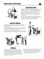 3
3
-
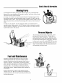 4
4
-
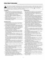 5
5
-
 6
6
-
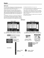 7
7
-
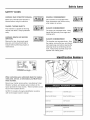 8
8
-
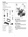 9
9
-
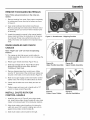 10
10
-
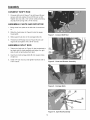 11
11
-
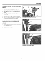 12
12
-
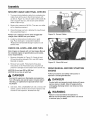 13
13
-
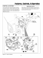 14
14
-
 15
15
-
 16
16
-
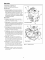 17
17
-
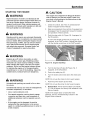 18
18
-
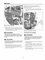 19
19
-
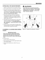 20
20
-
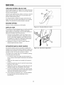 21
21
-
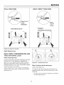 22
22
-
 23
23
-
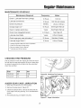 24
24
-
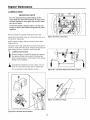 25
25
-
 26
26
-
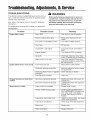 27
27
-
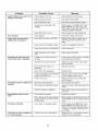 28
28
-
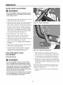 29
29
-
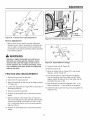 30
30
-
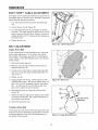 31
31
-
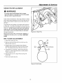 32
32
-
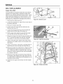 33
33
-
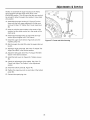 34
34
-
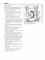 35
35
-
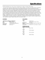 36
36
-
 37
37
-
 38
38
-
 39
39
-
 40
40
-
 41
41
-
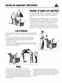 42
42
-
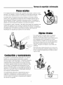 43
43
-
 44
44
-
 45
45
-
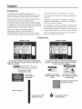 46
46
-
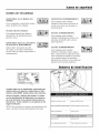 47
47
-
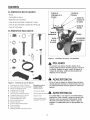 48
48
-
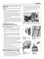 49
49
-
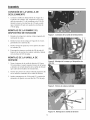 50
50
-
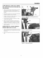 51
51
-
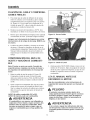 52
52
-
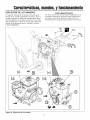 53
53
-
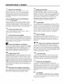 54
54
-
 55
55
-
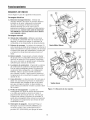 56
56
-
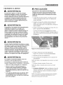 57
57
-
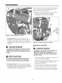 58
58
-
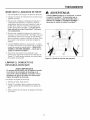 59
59
-
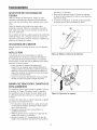 60
60
-
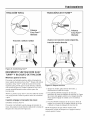 61
61
-
 62
62
-
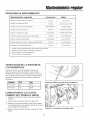 63
63
-
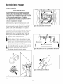 64
64
-
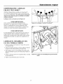 65
65
-
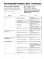 66
66
-
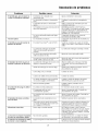 67
67
-
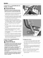 68
68
-
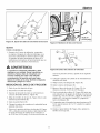 69
69
-
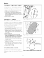 70
70
-
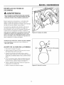 71
71
-
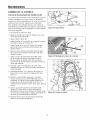 72
72
-
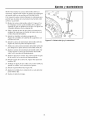 73
73
-
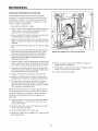 74
74
-
 75
75
-
 76
76
-
 77
77
-
 78
78


Snapper L1428E (1695572) El manual del propietario
- Categoría
- Lanzadores de nieve
- Tipo
- El manual del propietario
En otros idiomas
Documentos relacionados
Otros documentos
-
Simplicity SNW, DS, STEERABLE Guía del usuario
-
-
-
-
Briggs & Stratton 1696807 208cc 2-Stage El manual del propietario
-
Simplicity SNOWTHROWER, DUAL-STAGE, GROUP D, ANSI Manual de usuario
-
-
-
-
Craftsman 917881051 El manual del propietario