Pleasant Hearth 23-412-17 Assembly Instruction Manual
- Tipo
- Assembly Instruction Manual

1
ATTACH YOUR RECEIPT HERE
Serial Number ________________________________ Purchase Date _________________________________
Questions, problems, missing parts? Before returning to your retailer, call our customer
service department at 1-877-447-4768 8:30 AM – 4:30 PM EST, Monday – Friday
or email us at [email protected]
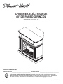
MODEL #23-412-17
Español p. 12
40" WALL/CORNER ELECTRIC FIREPLACE
20-10-308 06/09/2017

2
TABLE OF CONTENTS
Table of Contents. . . . . . . . . . . . . . . . . . . . . . . . . . . . . 2
Warranty ...................................3
What is covered ............................3
What is not covered .........................3
Pre-Assembly ...............................4
Assembly ...................................6
Service Parts ...............................11
IMPORTANT: Read all instructions and warnings carefully before starting installation.
Failure to follow these instructions may result in a possible electric shock, injury to persons, re hazard
and will void the warranty.
Please read the Installation & Operating Instructions before using this appliance.
CAUTION
PRODUCT DAMAGE MAY OCCUR.
Never attempt to disassemble or alter the product in any way not instructed by this manual.

3
WARRANTY
1-YEAR WARRANTY
WHAT IS COVERED
The manufacturer warrants that your new electric replace is free from manufacturing and material defects for a period of
one year from date of purchase, subject to the following conditions and limitations.
Variations in actual wood color and nishes which may result from natural characteristics of the wood, such as grain
patterns, mineral streaks and the like, are not considered defects. As wood continues to move and age you may notice
these slight differences in color, even on different parts of any individual unit. Sound knots and slight surface cracks are
the true personality of a quality piece of wood furniture.
This electric replace must be installed and operated at all times in accordance with the instructions furnished with the
product. Any alteration, willful abuse, accident, or misuse of the product shall nullify this warranty. This warranty is non-
transferrable, and is made to the original owner, provided that the purchase was made through an authorized supplier
of the manufacturer. This warranty is limited to the repair or replacement of part(s) found to be defective in material or
workmanship, provided that such part(s) have been subjected to normal conditions of use and service, after said defect
is conrmed by the manufacturer’s inspection. The manufacturer may, at its discretion, fully discharge all obligations with
respect to this warranty by refunding the wholesale price of the defective part(s).
WHAT IS NOT COVERED
Any installation, labor, construction, transportation, or other related costs/expenses arising from defective part(s), repair,
replacement, or otherwise of same, will not be covered by this warranty, nor shall the manufacturer assume responsibility
for same. Further, the manufacturer will not be responsible for any incidental, indirect, or consequential damages, except
as provided by law.
All other warranties - expressed or implied - with respect to the product, its components and accessories, or any
obligations/liabilities on the part of the manufacturer are hereby expressly excluded. The manufacturer neither assumes,
nor authorizes any third party to assume, on its behalf, any other liabilities with respect to the sale of this product. The
warranties as outlined within this document do not apply to nonmanufacturer accessories used in conjunction with the
installation of this product.
This warranty is void if: the replace has been operated in atmospheres contaminated by chlorine, uorine, or other
damaging chemicals; the replace is subjected to prolonged periods of dampness or condensation; the replace is
altered, willfully abused, damaged by accident, or misused in any way.
If warranty service is needed, contact the Customer Service Team at 1-877-447-4768, 8:30 a.m. – 4:30 p.m. EST,
Monday – Friday.
Make sure you have your warranty, your sales receipt, and the model/serial number of your product.
DO NOT ATTEMPT TO DO ANY SERVICE WORK YOURSELF.
1-877-447-4768 Monday to Friday from 8:30AM to 4:30PM (EST),
Web: www.ghpgroupinc.com
Email: [email protected]
Canada: 271 Massey Road, Guelph, Ontario, Canada, N1K 1B2
USA: 6440 W. Howard Street, Niles, Illinois U.S.A. 60714

4
PRE-ASSEMBLY
PLANNING ASSEMBLY
Before beginning assembly of product, make sure all parts are present. Compare parts with the package contents list and
hardware contents list. If any part is missing or damaged, do not attempt to assemble the product.
Estimated Assembly Time: 30 minutes
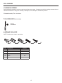
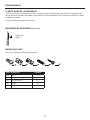
TOOLS REQUIRED (not included)
HARDWARE INCLUDED
Phillips
screwdriver
NOTE: Hardware not shown to actual size.
Part Description Quantity
AA Bolt 75
BB Short Connector 24
CC Long Connector 9
DD Dowel 34
EE Back Panel Screw 10

5
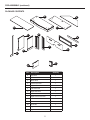
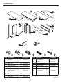
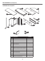
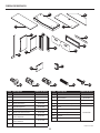
PACKAGE CONTENTS
PRE-ASSEMBLY (continued)
A
D
B
C
E
G
F
H
J
K
L
M
N
P
Part Description Quantity
A Top Panel 1
B Base 1
C Media Shelf 1
D Corner Top Panel 1
E Support 1
F Left Side Panel 1
G Right Side Panel 1
H Left Lower Front Panel 1
J Right Lower Front Panel 1
K Back Panel 1
L Removable Header 1
M Front Rail 1
N Upper Side Panel 2
P Upper Front Panel 2

6
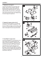
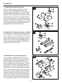
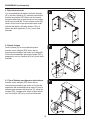
1. Preparing the side panels
Lay the left side panel (F) face down on a at
surface. Insert six small connectors (BB) into
predrilled holes and secure with screws (AA).
Repeat using the right side panel (G). Lay one
upper side panel (N) face down on a at surface.
Insert three long connectors (CC) into predrilled
holes and secure with screws (AA). Repeat using
the second upper side panel (N).
ASSEMBLY
1
2
3
2. Preparing the upper panels and rail
Lay the left lower front panel (H), the right lower
front panel (J), both upper front panels (P), and
the front rail (M) face down on a at surface. Insert
two short connectors (BB) into the two predrilled
holes in each panel. Secure using screws (AA).
F
F
G
G
H
H
P
P
J
J
M
N
N
AA
AA
AA
AA
AA
CC
BB
BB
DD
DD
3. Assembling the upper panels
Lay the left side panel (F) on a at surface. Insert
three dowels (DD) into predrilled holes in the
edge of the left side panel (F). Slip the left lower
front panel (H) over the dowels (DD) as shown
and secure with screws (AA). Repeat using the
right side panel (G) and the right lower front
panel (J). Lay both upper side panels (N) on a
at surface. Insert two dowels (DD) into predrilled
holes in the end of the upper side panels (N). Slip
the upper front panels (P) over dowels (DD) and
secure with screws (AA).
x2
x2
x2
x2

7
F
B
C
G
M
AA
AA
DD
DD
DD
ASSEMBLY (continued)
5
6
4
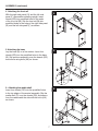
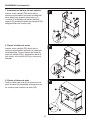
4. Attaching the front rail
With the right side panel (G) and the left side
panel (F) assemblies standing upright, insert
dowels (DD) into predrilled holes in the ends
of the front rail (M). Slip the front rail (M) into
predrilled holes in the edge of the right side panel
(G) and the left side panel (F) as shown.
5. Attaching the base
Lay the base (B) on a at surface. Insert four
dowels (DD) into the predrilled holes in the base
(B). Slip previous assembly over the dowels (DD)
and secure using bolts (AA) as shown.
6. Attaching the media shelf
Insert four dowels (DD) into the predrilled holes
in the top edges of the mantel assembly. Slip the
media shelf (C) over the dowels (DD) and secure
from the underneath the side with the bolts (AA)
as shown.

8
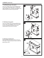
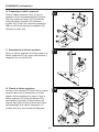
7. Installing the upper side panels
Insert four dowels (DD) into the predrilled holes
on each end of the media shelf (C). Attach the
upper side panel (N) assemblies by slipping over
dowels (DD) and secure using bolts (AA).
ASSEMBLY (continued)
7
8
9
8. Attaching the top panel
Insert four dowels (DD) into the predrilled holes
on each end of the assembly. Slip the top panel
(A) over the dowels (DD) and secure from
underneath with bolts (AA) as shown.
9. Attaching the back panel
Place the back panel (K) in position at the top,
back edge of the assembly and secure with back
panel screws (EE).
AA
AA
DD
EE
DD
C
A
K
N
N

9
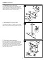
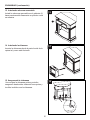
10. Preparing the corner top panel
Insert four dowels (DD) into the predrilled holes
on each end of the media shelf (C). Attach the
upper side panel (N) assemblies by slipping over
dowels (DD) and secure using bolts (AA).
ASSEMBLY (continued)
10
11
12
11. Assembling the corner top panel
Set the corner support (E) upright on the corner
panel (D) as shown and secure using a bolt (AA).
12. Attaching the corner top panel
Insert four dowels (DD) into the predrilled holes
in the top edge of the mantel assembly. Slip the
corner panel (D) over dowels (DD) until snug.
The lower edge of the support should be touching
the base edge of the mantel assembly. Secure
with bolts (AA) as shown.
AA
AA
AA
AA
DD
BB
E
E
D
D
D
CC

10
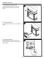
13. Installing the removable header
Install the removable header (L) to the base
cabinet by pressing it rmly into position as
shown.
ASSEMBLY (continued)
13
14
15
14. Installing the rebox
Insert the rebox from the front of the mantel as
shown.
15. Securing the rebox
Once the rebox is in position, secure from
behind using the brackets and screws included
with the rebox.
L

11
Printed in China
SERVICE PARTS
A
D
B
C
E
G
F
H
J
K
L
M
N
P
Part Description Part Number
A Top Panel 20-12-550
B Base 20-12-551
C Media Shelf 20-12-552
D Corner Top Panel 20-12-553
E Support 20-12-554
F Left Side Panel 20-12-555
G Right Side Panel 20-12-556
H Left Lower Front Panel 20-12-557
J Right Lower Front Panel 20-12-558
K Back Panel 20-12-559
Part Description Part Number
L Removable Header 20-12-560
M Front Rail 20-12-561
N Upper Side Panel 20-12-562
P Upper Front Panel 20-12-563
AA Bolt
20-09-520
BB Short Connector
CC Long Connector
DD Dowel
EE Back Panel Screw
AA BB CC DD
EE

12
¿Preguntas, problemas, piezas faltantes? Antes de volver a la tienda, comuníquese con nuestro
departamento de Servicio al Cliente llamando al 877-447-4768, de 8:30 a.m. a 4:30 p.m. hora del Este,
de lunes a viernes, o envíenos un correo electrónico a [email protected]
ADJUNTE SU RECIBO AQUÍ
Número de serie ________________________________ Fecha de compra _________________________________
MODELO #23-412-17
CHIMENEA ELÉCTRICA DE
40" DE PARED O RINCÓN
20-10-308 06/09/2017

13
TABLA DE CONTENIDO
Tabla de contenido ..........................13
Garantía. . . . . . . . . . . . . . . . . . . . . . . . . . . . . . . . . . . 14
Lo que está cubierto ........................14
Lo que no está cubierto .....................14
Pre-Ensamblar. . . . . . . . . . . . . . . . . . . . . . . . . . . . . . 15
Ensamblar .................................17
Piezas de repuesto ..........................22
IMPORTANTE: Lea cuidadosamente todas las instrucciones y advertencias antes de comenzar la instalación.
No seguir estas instrucciones puede resultar en un posible choque eléctrico, lesiones a las personas, peligro
de incendio y anulará la garantía.
Lea las Instrucciones de instalación y operación antes de usar este dispositivo.
PUEDEN OCURRIR DAÑOS AL PRODUCTO.
Nunca intente desmontar o alterar el producto en ninguna manera que no la indique este manual.
PRECAUCIÓN

14
GARANTÍA
GARANTÍA DE 1 AÑO
LO QUE ESTÁ CUBIERTO
El fabricante garantiza que su nueva chimenea eléctrica está libre de defectos de fabricación y materiales por un periodo
de un año a partir de la fecha de compra, sujeto a las siguientes condiciones y limitaciones.
Las variaciones en el color real de la madera y los acabados que pueden resultar de las características naturales de
la madera, como patrones de grano, marcas minerales y cosas semejantes, no son considerados defectos. A medida
la madera envejece, puede notar estas ligeras diferencias en color, incluso en partes diferentes de cualquier unidad
individual. Los nudos en buen estado y las grietas ligeras de la supercie son la verdadera personalidad de una pieza de
calidad de muebles de madera.
Esta chimenea eléctrica debe ser instalada y operada en todo momento de acuerdo con las instrucciones proporcionadas
con el producto. Cualquier alteración, abuso intencionado, accidente o mal uso del producto anulará esta garantía.
Esta garantía es intransferible y es hecha al propietario original, siempre que la compra haya sido hecha mediante
un proveedor autorizado del fabricante. Esta garantía está limitada a la reparación o reemplazo de pieza(s) que se
encuentre(n) defectuosa(s) en materiales o mano de obra, siempre que tal(es) pieza(s) haya(n) estado sujeta(s) a
condiciones normales de uso y servicio, luego de que dicho defecto sea conrmado por la inspección del fabricante.
El fabricante puede, a su discreción, liberarse de todas las obligaciones, con respecto a esta garantía mediante el
reembolso del precio al por mayor de la(s) pieza(s) defectuosa(s).
LO QUE NO ESTÁ CUBIERTO
Cualquier costo/gasto de instalación, trabajo, construcción, transporte u otros costos/gastos relacionados que surjan
de pieza(s) defectuosa(s), reparación, reemplazo o de otra manera relativa a los mismos, no serán cubiertos por esta
garantía, y tampoco el fabricante asumirá responsabilidad por lo mismo. Además, el fabricante no será responsable de
ningún daño incidental, indirecto o consecuente, excepto como lo establezca la ley.
Todas las otras garantías, expresas o implícitas, con respecto al producto, sus componentes y accesorios, o cualquier
obligación/responsabilidad civil sobre la pieza del fabricante, por la presente se excluyen expresamente. El fabricante
tampoco asume, ni autoriza a ninguna tercera parte a asumir, en su nombre, cualquier otra responsabilidad civil con
respecto a la venta de este producto. Las garantías como están descritas dentro de este documento, no aplican a
accesorios que no son del fabricante usados junto con la instalación de este producto.
Esta garantía no tiene validez si: la chimenea ha sido operado en atmósferas contaminadas por cloro, úor u otros
productos químicos perjudiciales; la chimenea está sujeta a periodos prolongados de humedad o condensación; la
chimenea es alterada, maltratada intencionalmente, dañada por accidente o usada incorrectamente en cualquier manera.
Si se necesita servicio de garantía, póngase en contacto con el Equipo de Servicio al Cliente llamando
al 1-877-447-4768 de lunes a viernes de 8:30 a.m. – 4:30 p.m., hora local del Este.
Asegúrese de tener su garantía, su recibo de venta y el número de modelo/serie de su producto.
NO INTENTE HACER TRABAJO DE SERVICIO USTED MISMO.
1-877-447-4768 Lunes a Viernes de 8:30AM to 4:30PM (hora del Este),
Sitio web: www.ghpgroupinc.com
Correo electrónico: [email protected]
Canadá: 271 Massey Road, Guelph, Ontario, Canada, N1K 1B2
EE.UU: 6440 W. Howard Street, Niles, Illinois U.S.A. 60714

15
PRE-ENSAMBLAR
PLANIFICACIÓN DE LA ENSAMBLAR
Antes de comenzar a ensamblar este producto, asegúrese de que todas las piezas estén presentes. Compare las pie-
zas con la lista de contenido del paquete y herraje incluido. Si hace falta alguna pieza o se encuentra dañada, no intente
ensamblar el producto.
Tiempo estimado de ensamblado: 30 minutos
HERRAMIENTAS REQUERIDAS (no incluido)
HERRAJE INCLUIDO
Desarmador
Phillips
Nota: No se muestra el herraje en el tamaño real.
Pieza Descripción Cantidad
AA Perno 75
BB Conectores Pequeños 24
CC Conectores Largos 9
DD Clavijas 34
EE Tornillos Para el Tablero de Atrás 10

16
CONTENIDO DEL PAQUETE
PRE-ENSAMBLAR (continuación)
A
D
B
C
E
G
F
H
J
K
L
M
N
P
Pieza Descripción Cantidad
A Tablero de Arriba 1
B Base 1
C Aparatos Electrónicos 1
D Tablero Esquinero 1
E Soporte Esquinero 1
F Tablero del Lado Izquierdo 1
G Tablero del Lado Derecho 1
H Tablero Frontal del Lado Inferior Izquierdo 1
J Tablero Frontal del Lado Inferior Derecho 1
K Tablero de Atrás 1
L Cabecera Removable 1
M Barra Frontal 1
N Tableros Laterales Superiores 2
P Tableros Frontales Superiores 2

17
1. Preparando los tableros laterales
Poner el tablero del lado izquierdo (F) hacia
abajo en una supercie plana. Insertar seis
conectores pequeños (BB) dentro de los huecos
pre-perforados y asegurarlos con tornillos (AA).
Repetir el mismo procedimiento usando el tablero
del lado derecho (G). Poner un tablero del lado
superior (N) hacia abajo en una supercie plana.
Insertar tres conectores largos (CC) dentro de los
huecos pre-perforados y asegurarlos con tornillos
(AA). Repetir el mismo procedimiento usando el
segundo tablero del lado superior (N).
ENSAMBLAR
1
2
3
2. Preparando los tableros superiores y la barra
Poner el tablero frontal del lado inferior izquierdo
(H), el tablero frontal del lado inferior derecho (J),
ambos tableros frontales superiores (P) y la barra
frontal (M) hacia abajo en una supercie plana.
Insertar dos conectores pequeños (BB) dentro de
los dos huecos pre-perforados en cada tablero.
Asegurarlos con tornillos (AA).
F
F
G
G
H
H
P
P
J
J
M
N
N
AA
AA
AA
AA
AA
CC
BB
BB
DD
DD
3. Ensamblando los tableros superiores
Poner el tablero del lado izquierdo (F) en una
supercie plana. Insertar tres clavijas (DD) dentro
de los huecos pre-perforados que están en el
borde del tablero de lado izquierdo (F). Poner el
tablero frontal del lado inferior izquierdo (H) sobre
las clavijas (DD) como lo muestra el diagrama y
asegurarlos con tornillos (AA). Repetir el mismo
procedimiento usando el tablero del lado derecho
(G) y el tablero frontal del lado inferior derecho (J).
Poner ambos tableros laterales superiores (N) en
una supercie plana. Insertar dos clavijas (DD)
dentro de los huecos pre-perforados que están en
el borde de los tableros laterales superiores (N).
Poner los tableros frontales superiores (P) sobre
las clavijas (DD) y asegurarlos con tornillos (AA).
x2
x2
x2
x2

18
F
B
C
G
M
AA
AA
DD
DD
DD
ENSAMBLAR (continuación)
5
6
4
4. Fijar la barra frontal
Con el ensamblaje del tablero del lado derecho
(G) y del lado izquierdo (F) parados hacia arriba,
insertar las clavijas (DD) dentro de los huecos
pre-perforados que se encuentran en los bordes
de la barra frontal (M). Poner la barra frontal (M)
dentro de los huecos pre-perforados que están
al borde del tablero del lado derecho (G) y el
tablero del lado izquierdo (F) tal y como está
ilustrado.
5. Fijando la base
Poner la base (B) en una supercie plana.
Insertar cuatro clavijas (DD) dentro de los
huecos pre-perforados que están en la base (B).
Poner este ensamblaje sobre las clavijas (DD) y
asegurarlos con los tornillos (AA) tal y como está
ilustrado.
6. Fijar el Estante para Aparatos electrónicos
Insertar cuatro clavijas (DD) dentro de los
huecos pre-perforados que están en los bordes
superiores del ensamblaje de la repisa. Poner el
estante para aparatos electrónicos (C) sobre las
clavijas (DD) y asegurarlos desde el lado inferior
con los tornillos (AA) tal y como está ilustrado.

19
7. Instalando los tableros del lado superior
Insertar cuatro clavijas (DD) dentro de los
huecos pre-perforados que están en cada lado
de la repisa para aparatos electrónicos (C).
Conectar el ensamblaje del tablero del lado
superior (N) poniéndolo sobre las clavijas (DD) y
asegurándolas con tornillos (AA).
ENSAMBLAR (continuación)
7
8
9
8. Fijando el tablero de arriba
Insertar cuatro clavijas (DD) dentro de los
huecos pre-perforados que están en cada lado
del ensamblaje. Poner el tablero de arriba (A)
sobre las clavijas (DD) y asegurarlos desde el
lado inferior con tornillos (AA) tal y como está
ilustrado.
9. Fijando el tablero de atrás
Poner el tablero de atrás (K) en posición en la
parte de atrás del ensamblaje y asegurarlo con
los tornillos para el tablero de atrás (EE).
AA
AA
DD
EE
DD
C
A
K
N
N

20
10. Preparando el tablero esquinero
Poner el tablero esquinero (D) y el soporte
esquinero (E) en una supercie plana y limpia.
Fijar tres conectores largos (CC) al borde de
arriba del tablero esquinero (D) utilizando
tornillos (AA). Poner dos conectores pequeños
(BB) en cada borde del soporte esquinero (E)
utilizando tornillos (AA).
ENSAMBLAR (continuación)
10
11
12
11. Ensamblando el tablero esquinero
Mover el soporte esquinero (E) hacia arriba en el
tablero esquinero (D) tal y como está ilustrado y
asegurarlo con un tornillo (AA).
12. Fijando el tablero esquinero
Insertar cuatro clavijas (DD) dentro de los huecos
pre-perforados que se encuentran en el lado
superior del ensamblaje de la repisa. Poner el
tablero esquinero (D) sobre las clavijas (DD)
hasta que esté ajustado. El borde inferior del
soporte debe estar tocando el borde de la base
del ensamblaje de la repisa. Asegurarlo con
tornillos (AA) tal y como muestra el diagrama.
AA
AA
AA
AA
DD
BB
E
E
D
D
D
CC

21
13. Instalando cabecera removable
Instale la cabecera removable en el gabinete (L)
base presionandola memente en poscion como
se muestra.
ENSAMBLAR (continuación)
13
14
15
14. Instalando la chimenea
Insertar la chimenea desde la parte frontal de la
repisa tal y como está ilustrado.
15. Asegurando la chimenea
Una vez que la chimenea esté en posición,
asegurarlo desde atrás utilizando los soportes y
tornillos incluidos con la chimenea.
L

22
Impreso en China
PIEZAS DE SERVICIO
A
D
B
C
E
G
F
H
J
K
L
M
N
P
Pieza Descripción
Numero de Pieza
A Tablero de Arriba 20-12-550
B Base 20-12-551
C Aparatos Electrónicos 20-12-552
D Tablero Esquinero 20-12-553
E Soporte Esquinero 20-12-554
F Tablero del Lado Izquierdo 20-12-555
G Tablero del Lado Derecho 20-12-556
H
Tablero Frontal del Lado
Inferior Izquierdo
20-12-557
J
Tablero Frontal del Lado
Inferior Derecho
20-12-558
K Tablero de Atrás 20-12-559
Pieza Descripción
Numero de Pieza
L Cabecera Removable 20-12-560
M Barra Frontal 20-12-561
N Tableros Laterales Superiores 20-12-562
P Tableros Frontales Superiores 20-12-563
AA Perno
20-09-520
BB Conectores Pequeños
CC Conectores Largos
DD Clavijas
EE Tornillos Para el Tablero de Atrás
AA BB CC DD
EE
-
 1
1
-
 2
2
-
 3
3
-
 4
4
-
 5
5
-
 6
6
-
 7
7
-
 8
8
-
 9
9
-
 10
10
-
 11
11
-
 12
12
-
 13
13
-
 14
14
-
 15
15
-
 16
16
-
 17
17
-
 18
18
-
 19
19
-
 20
20
-
 21
21
-
 22
22


Pleasant Hearth 23-412-17 Assembly Instruction Manual
- Tipo
- Assembly Instruction Manual
en otros idiomas
- English: Pleasant Hearth 23-412-17
Artículos relacionados
-
Pleasant Hearth 248-12-68M Assembly Instructions Manual
-
-
-
-
-
-
Pleasant Hearth 238-33-86M Manual de usuario
-