mundoclima Series MU-GC “Superficial Air Curtain Great Air Flow” Guía de instalación
- Tipo
- Guía de instalación

EC06720 - EC06727
www.mundoclima.com
MU-GC: A/W/W2F/R3

Thi
s manual is an integral part of the device and it must be delivered to the
user together with the device. In order to ensure correct operation of the
equi
pment, get thoroughly acquainted with this manual and keep it for the
fu
ture.
The
devices may only be installed and operated in conditions for which they
have
been designed. Any other application, inconsistent with this manual,
may lead to the occurrence of accidents with dangerous consequences.
Ev
ery effort must be made in order to eliminate the possibility of improper
us
e of the device. Access of unauthorized persons to the device should be
restricted, and the operating personnel should be trained. The manufacturer
bear
s no responsibility for damage resulting from incorrect installation,
im
proper operating, or not getting acquainted with the guidelines of the
manufacturer manual.
RE
COMMENDATIONS AND REQUIRED SAFETY MEASURES
• Ge
t acquainted with this operation manual before performing any
wo
rks at the device.
• The
device may only be installed by qualified personnel with adequate
aut
horisations and skills.
• In
the building where ventilation causes underpressure, air curtain
ma
y have limited efficiency
• Wh
en performing works at the device, remember about your own
sa
fety.
• Du
ring installation, electrical connection, connection to the heating
me
dium, start-up, repairs and maintenance of air curtains, observe the
co
mmonly recognized safety standards and regulations.
TA
BLE OF CONTENTS
Thank you for purchasing the MU-GC air curtain.
This operation manual has been issued by the Salvador Escoda SA company.
The manufacturer reserves the right to make revisions and changes in the
operation manual at any time and without notice, and also to make changes
in the device without influencing its operation.
2
ÍNDICE
1. INFORMACIÓN GENERAL......................................................................... 3
2. ESPECIFICACIONES TÉCNICAS .................................................................. 4
2.1. MATERIALS ....................................................................................... 4
2.2. DIMENSIONES .................................................................................. 5
2.3. NIVEL DE PRESIÓN ACÚSTICA ........................................................... 5
2.4. CAUDAL DE AIRE .............................................................................. 5
2.5. VELOC. DE CAUDAL DE AIRE ............................................................. 5
3. TABLAS DE CAPACIDAD CALORÍFICA ....................................................... 6
4. INSTALACIÓN ........................................................................................... 8
5. ESQUEMA ELÉCTRICO............................................................................. 10
7. GUÍA PARA CONEXIÓN CON TUBERÍA ................................................... 11
8. FUNCIONAMIENTO ................................................................................ 11
9. LIMPIEZA Y CONSERVACIÓN.... ................................................................. 12
10. AJUSTE DE LA REJILLA DE SALIDA DE AIRE ............................................. 12
11. MANTENIMIENTO ................................................................................. 13
Le agradecemos que haya adquirido la cortina de aire MU-GC
Este manual de uso e instalación se ha realizado en la empresa Salvador
Escoda S.A. El fabricante se reserva el derecho de hacer comprobaciones y
cambios en el manual en cualquier momento y sin previo aviso así como de
realizar cambios en el dispositivo que no afecten su funcionamiento.
Este manual es parte integrante de la unidad y se debe entregar junto con
ella. Para asegurar un buen funcionamiento del equipo, familiarícese con el
contenido de este manual y consérvelo para consultas futuras.
para las que ha sido diseñada. Cualquier otro uso que no coincida con este
manual puede provocar accidentes con consecuencias graves. Se debe
una formación. El fabricante no se hace responsable de los daños como
consecuencia de una mala instalación, mal uso o no atención a las
instrucciones que se describen en este manual del fabricante.
RECOMENDACIONES Y MEDIDAS DE SEGURIDAD
Familiarícese con este manual de uso antes de realizar trabajos
en la unidad.
La unidad solo se puede instalar por personal calificado con las
habilidades y autorizaciones reglamentarias.
En el edificio dónde la ventilación causa baja presión, la cortina
de aire puede tener una eficiencia limitada.
Cuando se realicen trabajos en la unidad, recuerde tomar todas
las medidas para su seguridad.
Durante la instalación, la conexión eléctrica, la conexión de la
calefacción, la puesta en marcha, la reparación y el mantenimiento de
las cortinas de aire, observe las normas y normas de seguridad
comúnmente reconocidas.
unidad a personal no autorizado. Los operarios de la unidad deben pasar
evitar siempre el mal uso de la unidad. Se debe restringir el uso de la
La unidad solo se puede instalar y poner en marcha en las condiciones
6. GUÍA PARA CONEXIÓN C/ALIMENTACIÓN ELÉCTRICA ........................................................... 11

1.
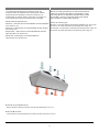
GENERAL INFORMATION
MU-GC air curtain generating an air barrier which protects
in
terior from external environment (its temperature, solids
and smog). MU-GC is dedicated to operate indoor and can
be mounted in vertical or horizontal position and chained
with next MU-GC creating wider air barrier.
MU-GC air curtains types:
ai
r inlet; air outlet;
* Ve
rtical range of nonisothermal stream (at velocity boundary equal above 3,0 m/s).
MU-GC-A - air curtain without heat exchanger (ambient) max. range 7,5m*;
MU-GC-W - air curtain with water heat exchanger max. range 7m*;
MU-GC-W2F - air curtain with 2-row water heat exchanger max. range 7m*;
MU-GC-R3- air curtain with electric heat exchanger max. range 7m*;
3
1.INFORMACIÓN GENERAL
La cortina de aire MU-GC genera una barrera de aire que
protege el interior del ambiente externo (temperatura, sólidos y
smog). MU-GC está dedicado a funcionar en interiores y se
puede montar en posición vertical u horizontal y en conexión con
el próximo MU-GC creando una barrera de aire más amplia.
MU-GC tipos de cortinas de aire:
MU-GC-A - cortina de aire sin intercambiador de calor (ambiente)
máx. alcance 7,5 m.
MU-GC-W - cortina de aire con intercambiador de calor de agua
máx. alcance 7m;
MU-GC-W2F - cortina de aire con intercambiador de calor de
agua de 2 filas m áx. alcance 7m*
MU-GC-R3- cortina de aire con intercambiador de
calor eléctrico máx. alcance 7m*;
entrada de aire; salida de aire,
* Rango vertical de caudal no isotérmica, límite de velocidad superior a 3,0 m / s).

2.
TECHNICAL DATA
2.
1. CONSTRUCTION
Fan – axi
al fan with metal blades; IP54;
Heat exchanger – CU-AL; connection
3
/
4
”;
El
ectrical heater – aluminum PTC heating element;
Casing – galvanized steel ;
– nozzle made of ABS, black colour
– air blades: plastic, RAL 7016
Mounting bracket – galvanized steel.
Fan
power supply [V/Hz]
230/
50
230/
50
2,
0
2,
6
2,
8
3,
0
3,
9
4,
2
Fan power consumption [kW]
0,
4
0,
52
0,
64
0,
6
0,
78
0,
96
IP 54
Heating el
ements power supply [V/Hz]
3x400/
50
3x400/
50
He
ating capacity [kW]
9,
0
10,
5
12,
0
16,
5
18,
5
20,
0
Cu
rrent consumption [A]
13 15 17 23 26 29
Temperature rise [
o
C]
12 9 7 12 9 7
Max. water te
mperature [
o
C]
130 130
Ma
x. water pressure [MPa]
1,
6
1,
6
Connec
tion [”]
3
/
4
3
/
4
We
ight [kg]
47,
4
43 49,
8
51,
8
62 58 67 66,
4
Weight of
unit filled with water [kg]
49,
7
- - 56,
4
64,
3
- - 71,
0
1 step 2 step 3 step 1 step 2 step 3 step
MU-GC-15/12-R3
MU-GC-20/20-R3
MU-GC-15-A; MU-GC-15-W; MU-GC-15-W2F
MU-GC-20-A; MU-GC-20-W; MU-GC-20-W2F
MU-GC-15-W; MU-GC-15-W2F
MU-GC-20-W; MU-GC-20-W2F
MU-GC
-15-W
MU-GC
-15-A
MU-GC
-15/12-R3
MU-GC
-15-W2F
MU-GC
-20-W
MU-GC
-20-A
MU-GC
-20/20-R3
MU-GC
-20-W2F
* MU-GC-15/12-R3; MU-GC-20/20-R3 temperature increase at inlet air 10ºC
4
2. ESPECIFICACIONES TÉCNICAS
Suministro eléct. ventil. [V/Hz]
Fan
current
co
nsumption [A]
Consumo de corriente del ventilador [A]
Consumo de potencia del ventilador [kW]
Veloc. 1 Veloc. 2 Veloc. 3 Veloc. 1 Veloc. 2 Veloc. 3
Suministro eléct. de resistencias. [V/Hz]
Capacidad de calefacción [kW]
Corriente consumida [A]
Aumento de la temp. [ºC]
Temp. máx. de entrada de agua [⁰C]
Presión máxima de agua [MPa]
Conexión [”]
Peso (kg)
Peso del equipo lleno de agua [kg]
* MU-GC-15/12-R3; MU-GC-20/20-R3 aumento de la temp. en entrada de aire 10ºC
2.1. FABRICACIÓN
Vent. -
Ventilador axial con lamas metálicas, IP54;
▪
Intercambiador de calor - CU-AL; conexión 3/4";
▪
Resistencia eléctrica - elemento de calefacción PTC aluminio;
▪
Carcasa - acero galvanizado ;
–
boquilla hecha de ABS, color negro
–
lamas de aire: plástico, RAL 7016
▪
Soporte de montaje -acero galvanizado.

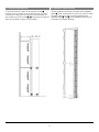
2.
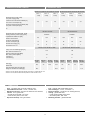
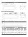
2. DIMENSIONS
*Above a sample of holders position. Location of those elements for various installation positions are shown in 4th chapter.
2.
3. ACOUSTIC PRESSURE LEVEL
3 60dB
(A)
62dB
(A)
2 54dB
(A)
56dB
(A)
1 49dB
(A)
51dB
(A)
* Acoustic pressure level measured in the room of average sound absorption, capacity 500 m
3
, a
t distance of 3 m from the unit.
2.4. A
IR VOLUME
3 6500
m
3
/h 6200
m
3
/h 6300
m
3
/h 5700 m
3
/h 8100
m
3
/h 8200
m
3
/h 8600 m
3
/h 7600
m
3
/h
2 5400
m
3
/h 5100
m
3
/h 5200
m
3
/h 4600 m
3
/h 6200
m
3
/h 6300
m
3
/h 6500 m
3
/h 5700
m
3
/h
1 4300
m
3
/h 4000
m
3
/h 4100
m
3
/h 3500 m
3
/h 5100
m
3
/h 5200
m
3
/h 5400 m
3
/h 4600
m
3
/h
MU-GC-15-A; MU-GC-15-W; MU-GC-15-W2F; MU-GC-15/12-R3
MU-GC-20-A; MU-GC-20-W; MU-GC-20-W2F; MU-GC-20/20-R3
Step
Step
MU-GC-15-A; MU-GC-15-W; MU-GC-15-W2F; MU-GC-15/12-R3
MU-GC-20-A; MU-GC-20-W; MU-GC-20-W2F; MU-GC-20/20-R3
MU-GC-15-A MU-GC-15-W
MU-GC-15-W2F
MU-GC-15/12-R3
MU-GC-20-A MU-GC-20-W
MU-GC-20-W2F
MU-GC-20/20-R3
5
2.2. DIMENSIONES
* Arriba se muestra la posición de las sujeciones. La ubicación de esos elementos para varias posiciones de instalación se muestra en el
capítulo 4.
2.3. NIVEL DE PRESI
Ó
N AC
Ú
STICA
Vel.
* El nivel de presión acústica medido en una sala con capacidad de absorción acústica media, y un volumen de 500 m
3
,
a una distancia de 3 m de la unidad.
2.4. CAUDAL DE AIRE
Vel.

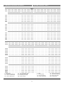
3. HEATING CAPACITY TABLE
Tp1 PT Qw ∆pw Tp2 PT Qw ∆pw Tp2 PT Qw ∆pw Tp2 PT Qw ∆pw Tp2
°C kW l/h kPa °C kW l/h kPa °C kW l/h kPa °C kW l/h kPa °C
Tw1/Tw2 = 90/70°C Tw1/Tw2 = 80/60°C Tw1/Tw2 = 70/50°C Tw1/Tw2 = 60/40°C
V1 = 4000 m
3
/h
0
27,
0
1190 5 19,
0
23,
2
1020 5 16,
0
19,
5
850 4 13,
5
15,
7
680 4 11,
0
5
25,
0
1100 6 22,
5
21,
2
930 5 20,
0
17,
5
770 3 17,
5
13,
7
600 3 14,
5
10
22,
9
1010 5 26,
5
19,
2
850 4 24,
0
15,
6
680 4 21,
0
11,
8
520 2 18,
5
15
21,
0
920 4 30,
5
17,
3
760 5 27,
5
13,
6
600 3 22,
5
10,
0
430 4 22,
5
20
19,0 840 4 34,0 15,4 680 4 31,5 11,8 520 2 29,0 8,1 350 3 26,0
V2
=5100 m
3
/h
0
31,
2
1370 7 17,
0
26,
8
1180 5 14,
5
22,
4
980 5 12,
0
18,
0
790 3 10,
0
5
28,
8
1270 6 21,
0
24,
5
1070 6 18,
5
20,
1
880 4 16,
0
15,
8
690 4 14,
0
10
26,
4
1170 5 25,
0
22,
2
970 5 22,
5
17,
9
780 3 20,
0
13,
6
590 3 17,
5
15
24,
1
1060 6 29,
0
19,
9
880 4 26,
5
15,
7
690 4 24,
0
11,
4
500 2 21,
5
20
21,
9
960 5 33,
0
17,
7
780 3 30,
5
13,
5
590 3 28,
0
9,
3
410 3 25,
5
V3
= 6200 m
3
/h
0
34,
8
1530 9 15,
5
29,
9
1310 7 13,
5
25,
0
1090 6 11,
0
20,
1
880 4 9,
0
5
32,
1
1420 8 19,
5
27,
3
1200 6 17,
5
22,
4
980 5 15,
5
17,
6
770 3 13,
0
10
29,
5
1300 6 23,
5
24,
8
1090 6 21,
5
20,
0
870 4 19,
5
15,
1
660 4 17,
0
15
27,
0
1190 5 28,
0
22,
2
980 5 25,
5
17,
5
770 3 23,
5
12,
7
550 3 21,
0
20
24,5 1080 6 32,0 19,8 870 4 29,5 15,1 660 4 27,5 10,4 450 4 25,0
Tp1 PT Qw ∆pw Tp2 PT Qw ∆pw Tp2 PT Qw ∆pw Tp2 PT Qw ∆pw Tp2
°C kW l/h kP
a
°C kW l/h kP
a
°C kW l/h kP
a
°C kW l/h kP
a
°C
Tw
1/Tw2 = 90/70°C
Tw
1/Tw2 = 80/60°C
Tw
1/Tw2 = 70/50°C
Tw
1/Tw2 = 60/40°C
V1
= 5100 m
3
/h
0
29,
3
1290 6 17,
5
25,
3
1110 6 15,
5
21,
1
920 5 13,
0
17,
0
740 5 10,
5
5
27,
1
1190 5 21,
5
23,
0
1010 5 19,
0
19,
0
830 4 16,
5
14,
9
650 4 14,
0
10
24,
9
1100 6 25,
5
20,
9
920 4 23,
0
16,
9
740 5 20,
5
12,
8
560 3 18,
0
15
22,
7
1000 5 29,
5
18,
8
820 4 27,
0
14,
8
650 4 24,
5
10,
8
470 4 22,
0
20
20,
6
910 4 33,
5
16,
7
730 5 31,
0
12,
8
560 3 28,
5
8,
8
380 3 25,
5
V2
=6200 m
3
/h
0
33,
2
1460 8 16,
0
28,
5
1250 6 14,
0
23,
9
1040 6 11,
5
19,
2
840 4 9,
4
5
30,6 1350 7 20,0 26,0 1140 5 18,0 21,4 940 5 15,5 16,8 730 5 13,5
10
28,
2
1240 6 24,
5
23,
6
1040 6 22,
0
19,
0
830 4 19,
5
14,
5
630 4 17,
5
15
25,
7
1130 5 28,
0
21,
2
930 5 26,
0
16,
7
730 5 23,
5
12,
1
530 3 21,
5
20
23,
3
1030 5 32,
0
18,
9
830 4 30,
0
14,
4
630 4 27,
5
9,
9
430 4 25,
0
V3
= 8100 m
3
/h
0
38,
9
1720 9 14,
5
33,
5
1470 8 12,
0
28,
0
1220 6 10,
0
22,
4
980 5 8,
0
5
36,
0
1580 7 18,
5
30,
5
1340 7 16,
5
25,
1
1100 6 14,
5
19,
6
860 4 12,
5
10
33,
1
1460 8 22,
5
27,
7
1220 6 20,
5
22,
3
980 5 18,
5
16,
9
740 5 16,
5
15
30,
2
1330 7 26,
5
24,
9
1090 6 24,
5
19,
6
860 4 22,
5
14,
2
620 3 20,
5
20
27,
4
1210 6 31,
0
22,
1
970 5 28,
5
16,
9
740 5 26,
5
11,
6
500 2 24,
5
MU-GC-15-W
MU-GC-20-W
V - Air flow
PT - Heating capacity
Tp1 - Inlet air temperature
Tp2 - Outlet air temperature
Tw1 - Inlet water temperature
Tw2 - Outlet water temperature
Qw - Heating water stream
pw - water pressure
Δ
6
3. TABLAS DE CAPACIDAD CALORÍFICA
V - Caudal de aire
PT - Capacidad de calefacción
Tp1 - Temp. de entrada de aire
Tp2 - Temp. de salida de aire
Tw1 - Temp. de entrada de agua
Tw2 - Temp. de salida de agua
Qw - Caudal de agua caliente
Δ pw - presión de agua

Tp1 PT Qw ∆pw Tp2 PT Qw ∆pw Tp2 PT Qw ∆pw Tp2 PT Qw ∆pw Tp2
°C kW l/h kPa °C kW l/h kPa °C kW l/h kPa °C kW l/h kPa °C
Tw1/Tw2 = 90/70°C Tw1/Tw2 = 80/60°C Tw1/Tw2 = 70/50°C Tw1/Tw2 = 60/40°C
V1 = 3500 m
3
/h
0
48,
2
2120 3 38 41,
4
1820 3 33 34,
6
1520 4 28 27,
8
1210 2 22
5
44,
4
1960 3 41 37,
8
1660 2 36 31,
0
1360 3 30 24,
3
1060 2 25
10
40,
8
1800 2 44 34,
2
1500 3 38 27,
6
1210 2 33 20,
9
910 2 27
15
37,
2
1640 2 46 30,
7
1350 3 41 24,
2
1060 3 35 17,
6
770 3 30
20
33,8 1490 3 49 27,3 1200 2 43 20,8 910 2 38 14,3 620 2 32
V2
=4600 m
3
/h
0
57,
3
2520 5 35 49,
2
2160 4 30 41,
0
1800 3 25 32,
9
1430 3 20
5
52,
9
2330 4 38 44,
9
1970 3 33 36,
8
1610 2 28 28,
7
1250 2 23
10
48,
5
2140 3 40 40,
6
1780 2 36 32,
6
1430 3 31 24,
7
1080 3 26
15
44,
3
1950 3 43 36,
5
1600 2 38 28,
6
1250 2 33 20,
7
900 3 28
20
40,
2
1770 2 46 32,
4
1420 3 41 24,
6
1080 3 36 16,
8
730 3 31
V3
= 5700 m
3
/h
0
65,
2
2870 4 32 56,
0
2460 4 27 46,
6
2040 3 23 37,
3
1620 2 18
5
60,
2
2650 4 35 51,
1
2240 4 30 41,
8
1830 3 26 32,
6
1420 3 21
10
55,
3
2440 4 38 46,
2
2030 3 33 37,
1
1620 2 29 27,
9
1220 2 24
15
50,
5
2220 4 41 41,
5
1820 3 36 32,
5
1420 3 32 23,
4
1020 3 27
20
45,7 2020 3 44 36,8 1620 2 39 28,0 1220 2 35 19,0 830 2 30
Tp1 PT Qw ∆pw Tp2 PT Qw ∆pw Tp2 PT Qw ∆pw Tp2 PT Qw ∆pw Tp2
°C kW l/h kP
a
°C kW l/h kP
a
°C kW l/h kP
a
°C kW l/h kP
a
°C
Tw
1/Tw2 = 90/70°C
Tw
1/Tw2 = 80/60°C
Tw
1/Tw2 = 70/50°C
Tw
1/Tw2 = 60/40°C
V1
= 4600 m
3
/h
0
53,
3
2350 4 36 45,
8
2010 3 31 38,
2
1670 2 26 30,
6
1330 3 21
5
49,
2
2170 3 39 41,
7
1830 3 34 34,
3
1500 4 29 26,
8
1170 2 24
10
45,
2
1990 3 42 37,
8
1660 2 37 30,
4
1330 3 31 23,
0
1000 3 26
15
41,
2
1820 2 45 33,
9
1490 3 39 26,
7
1170 2 34 19,
3
840 2 29
20
37,
4
1650 2 47 30,
2
1330 3 42 23,
0
1010 3 37 15,
7
680 3 31
V2
=5700 m
3
/h
0
61,
7
2720 4 33 53,
0
2330 4 28 44,
2
1930 3 24 35,
3
1540 4 19
5
57,0 2510 5 36 48,3 2120 3 31 39,6 1730 2 27 30,9 1350 3 22
10
52,
3
2310 4 39 43,
7
1920 3 34 35,
1
1540 4 30 26,
5
1160 2 25
15
47,
7
2100 3 42 39,
3
1730 2 37 30,
8
1350 3 32 22,
2
970 3 28
20
43,
3
1910 3 45 34,
9
1530 4 40 26,
5
1160 2 35 18,
0
790 2 30
V3
= 7600 m
3
/h
0
74,
2
3270 5 29 63,
5
2790 4 25 52,
9
2310 4 21 42,
2
1840 3 17
5
68,
5
3020 5 32 58,
0
2550 5 28 47,
4
2080 3 24 36,
8
1610 2 20
10
62,
8
2770 4 36 52,
5
2300 4 31 42,
1
1840 3 27 31,
6
1380 3 23
15
57,
4
2530 5 39 47,
1
2070 3 35 36,
8
1610 2 30 26,
5
1150 2 26
20
52,
0
2290 4 42 41,
9
1840 3 38 31,
7
1390 3 33 21,
4
930 2 29
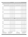
MU-GC-15-W2F
MU-GC-20-W2F
7
3. HEATING CAPACITY TABLE
3. TABLAS DE CAPACIDAD CALORÍFICA
V - Air flow
PT - Heating capacity
Tp1 - Inlet air temperature
Tp2 - Outlet air temperature
Tw1 - Inlet water temperature
Tw2 - Outlet water temperature
Qw - Heating water stream
pw - water pressure
Δ
V - Caudal de aire
PT - Capacidad de calefacción
Tp1 - Temp. de entrada de aire
Tp2 - Temp. de salida de aire
Tw1 - Temp. de entrada de agua
Tw2 - Temp. de salida de agua
Qw - Caudal de agua caliente
Δ pw - presión de agua

4.
INSTALATION
MU-GC air curtains are delivered with set of hangers which allow
in
stall them horizontally as well as vertically. Installation pins
and screws required for fix unit to the wall/floor/post are not
included.
Max size of covered doorway:
- vertical single side installation: max width 7,5 m,
- vertical double side installation: max width 13 m,
- horizontal installation: max height level 7,5 m,.
Attention:
Screw air curtain to the wall/floor/post before first start up.
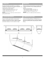
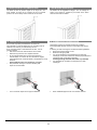
4.
1. HORIZONTAL INSTALATION
In
case of horizontal installation use installation plate and
mount unit via threaded pins M10 (not included). Single unit is
mounted on 4 installation plates, two units on 6pcs. Installation
plates are used to screw units among themselves as show on
drawing.
8
4. INSTALACIÓN
4.1. INSTALACIÓN HORIZONTAL
Las cortinas de aire MU-GC se entregan con un conjunto de
colgadores que permiten instalarlas horizontal y verticalmente.
Los pasadores de instalación y tornillos necesarios para fijar la unidad
a la pared / suelo / columna no se incluyen.
Tamaño máximo de la puerta cubierta:
-
instalación sencilla lateral vertical: ancho máx. 7,5 m,
-
instalación doble lateral vertical: ancho máx. 13 m,
-
instalación horizontal: altura máx. 7,5 m.
Atención:
Atornille la cortina de aire a la pared / piso / columna antes de la
primera puesta en marcha.
En caso de instalación horizontal utilice la placa de montaje y la
unidad de montaje mediante pasadores roscados M10 (no
incluidos). La unidad sencilla se monta en 4 placas de instalación,
dos unidades en 6 placas. Las placas de instalación se utilizan
para atornillar unidades entre sí como muestran en el dibujo.

4.2. VER
TICAL INSTALLATION
Ve
rtical installation is executed via included in set installation
plates , which should mount unit to the floor. Next air curtain
should be putted on the first one and screwed with it via
installation plate and , those installation plates must be
anchored to the wall/post (drawing).
9
4.2. INSTALACIÓN VERTICAL
La instalación vertical se realiza con las placas de montaje
incluidas en el kit, que deben montar la unidad al suelo. La próxima
cortina de aire se debe poner en la primera y debe atornillarse con
ésta mediante la placa de montaje y , estas placas de instalación
deben estar ancladas a la pared / columna (dibujo).

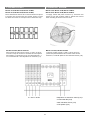
5. CONNECTING DI
AGRAM
To
supply curtain with power connect it by connection box
closest to unit side. Protract cable by glands and connect
wires according to scheme from box cover.
To
start up curtain connect 3 x 400 V / 50 Hz current to
junction box placed between fan's nozzles. Next connect
terminals 1; 2 with RX splitter or other activation device (L;N).
MU-GC-15-A; MU-GC-15-W; MU-GC-15-W2F;
MU-GC-15/12-R3; MU-GC-20/20-R3
MU-GC-20-A; MU-GC-20-W; MU-GC-20-W2F;
3 x 400 V / 50 Hz
230V activation device (L;N)
or RX splitter (V;N)
10
5. ESQUEMA ELÉCTRICO
MU-GC-15-A; MU-GC-15-W; MU-GC-15-W2F;
MU-GC-20-A; MU-GC-20-W; MU-GC-20-W2F;
Para la alimentación eléctrica de la cortina enchúfela a la caja de
la conexión más cercana al lado de la unidad. Tienda y conecte
los cables de acuerdo con el esquema de la cubierta de la caja.
MU-GC-15/12-R3; MU-GC-20/20-R3
Para encender la cortina de aire conecte 3 x 400 V / 50 Hz de
corriente a la caja de conexiones colocadas entre las boquillas
del ventilador. Los terminales que se conectarán después 1, 2
con concentrador RX u otros dispositivos de activación (L, N).
Dispositivo de activación
230V (L,N) o
concentrador RX (V;N)

6.
GUIDELINES FOR CONNECTION WITH POWER
SU
PPLY
Be
fore connecting the power supply check the correctness
of connection of the fan motor and the controllers. These
connections should be executed in accordance with their
technical documentation.
Be
fore connecting the power supply check whether the
mains voltage is in accordance with the voltage on the
device data shield.
Starting the device without connecting the ground
conductor is forbidden.
7. GUIDELINES FOR CONNECTION WITH PIPELINE
The
connection should be executed in a way which does
not induce stresses.
It is recommended to install vent valves at the highest
point of the system.
The system should be executed so that, in the case of a
failure, it is possible to disassemble the device. For this
purpose it is best to use shut-off valves just by the device.
The system with the heating medium must be protected
against an increase of the heating medium pressure
above the permissible value (1.6 MPa).
While screwing exchanger to pipeline - connecting stubs
has to be hold by wrench.
8. OPERATION
The
device is designed for operation inside buildings, at
temperatures above 0
o
C.
In low temperatures (below 0ºC)
there is a danger of freezing of the medium
The manufacturer bears no responsibility for damage of
the heat exchanger resulting from freezing of the medium
in the exchanger.
It is forbidden to place any objects on the heater or to hang any
objects on the connecting stubs.
The device must be inspected periodically. In the case of
incorrect operation of the device it should be switched off
immediately.
It is forbidden to use a damaged device. The manufacturer
bears no responsibility for damage resulting from the use
of a damaged device.
If it is necessary to clean the exchanger, be careful not to
damage the aluminium lamellas.
For the time of performing inspection or cleaning the
device, the electrical power supply should be
disconnected.
In case water is drained from the device for a longer
period of time, the exchanger tubes should be emptied
with compressed air.
11
6. GUÍA PARA CONEXIÓN C/ ALIMENTAC. ELÉCT.
7. GUÍA PARA CONEXIÓN CON TUBERÍA
▪
Antes de conectar la alimentación, compruebe que tanto las
conexiones del motor del ventilador como de los controles
son correctas. Estas conexiones se deben realizar de
acuerdo a lo especificado en la documentación técnica.
▪
Antes de conectar la alimentación compruebe si la
entrada de corriente se corresponde con la tensión
especificada en el diagrama escrito en el dispositivo.
▪
Queda prohibido encender el equipo sin la conexión
a tierra.
▪ La conexión se debe realizar de manera que no quede
tensada.
▪ Se recomienda instalar los purgadores en el punto más
alto del sistema.
▪ El sistema se debe encender de manera que en caso de
fallo sea posible desmontar la unidad. Para este propósito lo
ideal es usar válvulas de cierre en la unidad.
▪ El sistema con la resistencia debe estar protegido contra
el aumento de la presión del calor sobre el valor permitido
(1.6 MPa).
▪ Mientras atornilla el intercambiador a la tubería - para la
conexión se deben sujetar los extremos con llaves.
8. FUNCIONAMIENTO
▪ Este dispositivo está diseñado para que funcione dentro
de instalaciones a temperaturas superiores a 0 ºC. A
bajas temperaturas (bajo 0 ºC) existe el peligro de
congelamiento de la resistencia.
El fabricante no se responsabiliza por el daño del
intercambiador de calor como resultado de hielo en
el equipo.
No se permite colocar objetos en el radiador ni colgar
objetos en los extremos de las conexiones.
▪ El dispositivo se debe inspeccionar periódicamente. En
caso de mal funcionamiento del destratificador, se debe
apagar inmediatamente.
▪ Queda prohibido usar un equipo dañado. El fabricante no
se hace responsable por los daños como resultado del
uso de dispositivos dañados.
▪ Es necesario limpiar el intercambiador, cuide de no
dañar las lamas de aluminio.
▪ Durante la inspección o la limpieza de la unidad, se
debe desconectar de la electricidad.
▪ En caso de que salga agua de la unidad por mucho
tiempo, las tuberías del intercambiador se debe vaciar
con un compresor de aire.

9. AI
R BLADES REGULATION
Ai
r blades can be regulated in range ± 10º. To change an
angle of air stream is needed to put stress at the same
time for both ends of blades
10. CL
EANING AND CONSERVATION
Pe
riodically need to be checked exchanger condition.
Exchanger filled with dirt causes in heat output and air flow
drop.
If cleaning of heat exchanger is needed use listed guidelines.
Disconnect power supply of unit.
Dismount inlet grill guard
It is recommended to use pressured air to clean the
exchanger, air stream need to be directed perpendicular to
exchanger and moved along lamellas.
Cleaning heating elements with water is prohibited
It is prohibited to use water or sharp items to clean
exchanger.
Ot
her installed equipment do not need be cleaned
12
9. REGULACIÓN DE LAS LAMAS DE AIRE
Las lamas de aire se pueden regular en el rango de ± 10º.
Para cambiar el ángulo de la corriente de aire se necesita
presionar al mismo tiempo ambos extremos de las lamas.
10. LIMPIEZA Y CONSERVACIÓN
Se necesita comprobar periódicamente el estado del
intercambiador. El intercambiador lleno de suciedad causa la
salida de calor interna y la caída del flujo de aire.
Si es necesario limpiar el intercambiador de calor, use las
pautas indicadas.
▪ Desconecte la fuente de alimentación de la unidad.
▪ Desmonte la protección de la rejilla de entrada.
▪ Se recomienda utilizar aire a presión para limpiar el
intercambiador, la corriente de aire necesita ser dirigida
perpendicularmente al intercambiador y desplazada a lo largo
de lamas.
Está prohibido limpiar las resistencias con agua
▪ Está prohibido usar agua o artículos afilados para
limpiar el intercambiador.
▪ No es necesario limpiar otros equipos instalados.

Please contact your dealer in order to get acquitted with the
warranty terms and its limitation.
In the case of any irregularities in the device operation, please
contact the manufacturer’s service department.
The manufacturer bears no responsibility for operating the
device in a manner inconsistent with its purpose, by persons
not authorised for this, and for damage resulting from this!
Made in EU
SALVADOR ESCODA SA
Provenza 392 P2
08025 Barcelona
Spain
e-mail: [email protected]
www.mundoclima.com
Póngase en contacto con su proveedor para conocer
los términos de la garantía y sus limitaciones.
En caso de irregularidades en el funcionamiento de la
unidad, póngase en contacto con el servicio de asistencia al
cliente del fabricante.
¡El fabricante no se responsabiliza de los daños
causados por el mal manejo del equipo ni por usos para
otros propósitos por personas no autorizadas!
Hecho en UE
SALVADOR ESCODA SA
Provenza 392 P2
08025 Barcelona España
e-mail:
info@mundoclima.com
www.mundoclima.com
11. MANTENIMIENTO Y GARANTÍA
13

www.mundoclima.com
C/ PROVENZA 392 P2
08025 BARCELONA
SPAIN
(+34) 93 446 27 80
-
 1
1
-
 2
2
-
 3
3
-
 4
4
-
 5
5
-
 6
6
-
 7
7
-
 8
8
-
 9
9
-
 10
10
-
 11
11
-
 12
12
-
 13
13
-
 14
14


mundoclima Series MU-GC “Superficial Air Curtain Great Air Flow” Guía de instalación
- Tipo
- Guía de instalación
en otros idiomas
Artículos relacionados
Otros documentos
-
DeLOCK 60273 Ficha de datos
-
-
-
Koblenz AI-1240 Operation Instructions Manual
-
-
 DS18 G6.9Xi 6X9 Inch 3-Way Coaxial Speaker El manual del propietario
-
Samsung MIM-E03BN Guía de instalación
-
-
-
Samsung AE160JNYDEH/EU Manual de usuario
