mundoclima Series MU-EMP “Embedded Air Curtain” Guía de instalación
- Tipo
- Guía de instalación

EC06700 - EC06711
www.mundoclima.com
MU-EMP: A/W/W2F/R3

TABLE OF CONTENTS
1. GENERAL INFORMATION ....................................................................... 3
2.
TECHNICAL DATA
.................................................................................... 4
2.1. CONSTRUCTION ............................................................................... 4
2.2.
DIMENSIONS
.................................................................................... 5
2.3. ACOUSTIC PRESSURE LEVEL ............................................................. 5
2.4. AIR VOLUME
................................
.................................................... 5
2.5. AIR FLOW SPEED .............................................................................. 6
3.
HEAT CAPACITY TABLE ............................................................................ 6
4.
INSTALLATION ......................................................................................... 9
5.
CONTROL SYSTEMS ............................................................................... 11
5.2. CONNECTING GUIDE ...................................................................... 12
5.2. DRV
-EMP CONTROL SYSTEM .......................................................... 13
6.
DOOR CONTACT INSTALLATION ........................................................... 20
7.
GUIDELINES FOR CONNECTION WITH POWER SUPPLY ......................... 21
8.
GUIDELINES FOR CONNECTION WITH PIPELINE .................................... 21
9.
OPERATION ........................................................................................... 21
10.
CLEANING AND CONSERVATION ...........................................................
22
11.
OUTLET GRILL ADJUSTING..................................................................... 22
12.
SERVICE ................................................................................................. 23
This
manual is an integral part of the device and it must be delivered to the
user together with the device. In order to ensure correct operation of the
equipm
ent, get thoroughly acquainted with this manual and keep it for the
futu
re.
The devi
ces may only be installed and operated in conditions for which they
have been
designed. Any other application, inconsistent with this manual,
may lead to the occurrence of accidents with dangerous consequences.
Eve
ry effort must be made in order to eliminate the possibility of improper
use
of the device. Access of unauthorized persons to the device should be
restricted, and the operating personnel should be trained. The manufacturer
bears
no responsibility for damage resulting from incorrect installation,
imp
roper operating, or not getting acquainted with the guidelines of the
manufacturer manual.
RECOM
MENDATIONS AND REQUIRED SAFETY MEASURES
• Get
acquainted with this operation manual before performing any
wor
ks at the device.
• The devi
ce may only be installed by qualified personnel with adequate
author
isations and skills.
• In th
e building where ventilation causes underpressure, air curtain
may
have limited efficiency
• Whe
n performing works at the device, remember about your own
saf
ety.
• Dur
ing installation, electrical connection, connection to the heating
med
ium, start-up, repairs and maintenance of air curtains, observe the
com
monly recognized safety standards and regulations.
Thank you for purchasing the MU-EMP air curtain.
This operation manual has been issued by the Salvador Escoda SA company.
The manufacturer reserves the right to make revisions and changes in the
operation manual at any time and without notice, and also to make changes
in the device without influencing its operation.
2
ÍNDICE
1. INFORMACIÓN GENERAL......................................................................... 3
2. ESPECIFICACIONES TÉCNICAS .................................................................. 4
2.1. MATERIALS ....................................................................................... 4
2.2. DIMENSIONES .................................................................................. 5
2.3. NIVEL DE PRESIÓN ACÚSTICA ........................................................... 5
2.4. CAUDAL DE AIRE .............................................................................. 5
2.5. VELOC. DE CAUDAL DE AIRE ............................................................. 6
3. TABLAS DE CAPACIDAD CALORÍFICA ....................................................... 6
4. INSTALACIÓN ........................................................................................... 9
5. SISTEMAS DE CONTROL ......................................................................... 11
5.2. GUÍA DE CONEXIÓN ....................................................................... 12
5.2. SISTEMA DE CONTROL DRV-EMP ................................................... 13
6. INSTALACIÓN DEL CONTACTO DE LA PUERTA ...................................... 20
7. GUÍA PARA CONEXIÓN C/ ALIMENTAC. ELÉCTRICA ............................... 21
8. GUÍA PARA CONEXIÓN CON TUBERÍA ................................................... 21
9. FUNCIONAMIENTO ................................................................................ 21
10. LIMPIEZA Y CONSERVACIÓN ................................................................. 22
11. AJUSTE DE LA REJILLA DE SALIDA DE AIRE ............................................. 22
12. MANTENIMIENTO ................................................................................. 23
Le agradecemos que haya adquirido la cortina de aire MU-EMP.
Este manual de uso e instalación se ha realizado en la empresa Salvador
Escoda S.A. El fabricante se reserva el derecho de hacer comprobaciones y
cambios en el manual en cualquier momento y sin previo aviso así como de
realizar cambios en el dispositivo que no afecten su funcionamiento.
Este manual es parte integrante de la unidad y se debe entregar junto con
ella. Para asegurar un buen funcionamiento del equipo, familiarícese con el
contenido de este manual y consérvelo para consultas futuras.
La unidad solo se puede instalar y poner en marcha en las condiciones
para las que ha sido diseñada. Cualquier otro uso que no coincida con este
manual puede provocar accidentes con consecuencias graves. Se debe
evitar siempre el mal uso de la unidad. Se debe restringir el uso de la
unidad a personal no autorizado. Los operarios de la unidad deben pasar
una formación. El fabricante no se hace responsable de los daños como
consecuencia de una mala instalación, mal uso o no atención a las
instrucciones que se describen en este manual del fabricante.
RECOMENDACIONES Y MEDIDAS DE SEGURIDAD
Familiarícese con este manual de uso antes de realizar trabajos
en la unidad.
La unidad solo se puede instalar por personal calificado con las
habilidades y autorizaciones reglamentarias.
En el edificio dónde la ventilación causa baja presión, la cortina
de aire puede tener una eficiencia limitada.
Cuando se realicen trabajos en la unidad, recuerde tomar todas
las medidas para su seguridad.
Durante la instalación, la conexión eléctrica, la conexión de la
calefacción, la puesta en marcha, la reparación y el mantenimiento de
las cortinas de aire, observe las normas y normas de seguridad
comúnmente reconocidas.

1.GENERAL INFORMATION
Purpose of MU-EMP is to minimalize heat losses (or unwanted he
gains) by door openings. MU-EMP is a recessed type and can be
part suspended ceiling.
MU-EMP air curtains types:
MU-EMP-A - air curtain without heat exchanger (ambient) max. range 5m;
MU-EMP-W - air curtain with water heat exchanger max. range 5m;
MU-EMP-W2F - air curtain with 2-row water heat exchanger max. range 5m;
MU-EMP-R3- air curtain with electric heat exchanger max. range 5m;
3
1.INFORMACIÓN GENERAL
5m;
El propósito de MU-EMP es minimizar las pé
rdidas de calor (no
deseadas) por las aberturas de la puerta. MU-
EMP es una
unidad empotrada y se puede instalar en techo suspendido.
MU-EMP tipos de cortinas de aire:
MU-EMP-A - cortina de aire sin intercambiador de calor (ambiente)
máx. alcance 5m.
MU-EMP-W - cortina de aire con intercambiador de calor de agua
MU-EMP-W2F - cortina de aire con intercambiador de calor de agua
de 2 filas máx. alcance 5m.
MU-EMP-R3- cortina de aire con intercambiador de calor eléctrico
máx. alcance 5m.
máx. alcance 5m.

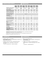
2. TECHNICAL DATA
supply [V/Hz]
230 / 50
3x400
/ 50
230 / 50
3x400
/ 50
230 / 50
3x400
/ 50
Power consumption [kW]
0,34 0,42 7,5 0,36 0,44 11,5 0,38 0,49 15,5
Current consumption [A]
1,5 1,9 11 1,6 2 16,6 1,7 2,2 22,4
IP / Insulation class
21 / F
Connecting stub [”]
½ - ½ - ½ -
Max. water temperature [
o
C]
95
-
95 - 95 -
Max. water pressure
[MPa]
1,6 - - 1,6 - - 1,6 - -
15 - 11 15 - 12 16 - 13
Weight [kg]
32,3 31,7 34,5 41,2 38,9 42,4 50 47,2 53,2
Weight of unit filled with
water [kg]
33,1 - - 42,4 - - 51,6 - -
2.1. CONSTRUCTION
Fan –
motor with plastic rotor;
Heat exchanger – copper-
aluminium, connecting stub ½”;
electrical heaters
PTC;
Casing– sheet steel RAL; color white RAL 9016,
– back elements -
expanded polypropylene EPP; colour
–
grey;
– air inlet fins - anodized aluminum
Power
MU-EMP
-10-W
MU-EMP
-10-A
MU-EMP
-10/8-R3
MU-EMP
-15-W
MU-EMP
-15-A
MU-EMP
-15/12-R3
MU-EMP
-20-W
MU-EMP
-20-A
MU-EMP
-20/16-R3
-10-W2F -15-W2F
-20-W2F
4
*MU-EMP-R3: Temperature increase at inlet air 10ºC
*MU-EMP-W/W2F: Temperature increase at inlet air 10ºC and heating agent temperature 90/70ºC
2. ESPECIFICACIONES TÉCNICAS
Suministro eléctrico
[V/Hz]
Consumo
[kW]
Corriente consumida [A]
IP/ Clase de aislamiento
Conexión [”]
Temp. máx entrada agua [ºC]
Presión máx. agua [MPa]
Aumento de la temp.
(∆T)
[ºC]*
Temperature
increase (∆T) [ºC]*
Peso [kg]
Peso del equipo lleno
de agua [kg]
*MU-EMP-W/W2F: Aumento de la temp. en la entrada de aire de 10ºC y otras fuentes de calor 90/70ºC
*MU-EMP-R3: Aumento de temp. en la entrada de aire 10ºC
2.1. FABRICACIÓN
ႛ
Ventilador - Motor con rotor plástico;
ႛ
Intercambiador de calor - cobre-aluminizado, conexión de ½”;
Resistencias eléctricas PTC;
ႛ
Carcasa– chapa de acero RAL; color blanco RAL 9016,
– elementos traseros - polipropileno extendido EPP,
color - gris;
– lamas de entrada de aire - aluminio anodizado

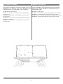
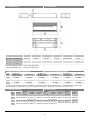
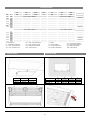
2.2. DIMENSIONS
A
B C
D
E
F
1057 mm
600 mm 561 mm 770 mm
297
*/284**
mm
96 mm
1546 mm
600 mm 561 mm 1207 mm
297
*/284**
mm
84 mm
2034 mm
600 mm 561 mm 1621 mm
297
*/284**
mm
157 mm
2.3. ACOUSTIC PRESSURE LEVEL
3
62 dB(A) 64 dB(A) 63 dB(A) 65 dB(A) 64 dB(A)
66 dB(A)
2
58 dB(A) 60 dB(A) 59 dB(A) 60 dB(A) 61 dB(A)
63 dB(A)
1
54 dB(A) 56 dB(A) 55 dB(A) 56 dB(A) 56 dB(A)
58 dB(A)
* Acoustic pressure level measured in the room of average sound absorption, capacity 500 m
3
, at distance of 3 m from the unit.
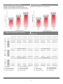
2.4. AIR VOLUME
Speed
3
3500 m
3
/h
2
2700 m
3
/h
1
2300 m
3
/h
MU-EMP-10-A/W/W2F/R3
MU-EMP-15-A/W/W2F/R3
MU-EMP-20-A/W/W2F/R3
* height for MU-EMP-W/W2F;
** height for MU-EMP-A/R3;
MU-EMP-10-W
MU-EMP-10/8-R3
MU-EMP-10-W2F
MU-EMP-10-A
MU-EMP-15-A
MU-EMP-15-W
MU-EMP-15/12-R3
MU-EMP-15-W2F
MU-EMP-20-A
MU-EMP-20-W
MU-EMP-20/16-R3
MU-EMP-20-W2F
MU-EMP-
5
2600 m
3
/h
2500 m
3
/h
2200 m
3
/h
10-A
MU-EMP-
10-W
10/8-R3
MU-EMP-
10-W2F
2400 m
3
/h
2300 m
3
/h
2000 m
3
/h
MU-EMP-
15-A
MU-EMP-
15-W
15/12-R3
MU-EMP-
15-W2F
4000 m
3
/h
3500 m
3
/h
3200 m
3
/h
4800 m
3
/h
4000 m
3
/h
3200 m
3
/h
MU-EMP-
20-A
MU-EMP-
20-W
20/16-R3
MU-EMP-
20-W2F
5200 m
3
/h
4300 m
3
/h
4000 m
3
/h
6600 m
3
/h
4300 m
3
/h
3600 m
3
/h
3800 m
3
/h
3200 m
3
/h
3000 m
3
/h
4900 m
3
/h
3900 m
3
/h
3800
m
3
/h
Speed
2.2. DIMENSIONES
* altura para MU-EMP-W/W2F;
** altura para MU-EMP-A/R3;
2.3. NIVEL DE PRESIÓN ACÚSTICA
Vel.
*
El nivel de presión acústica medido en la habitación de absorción acústica media, capacidad 500 m
3
, a una
distancia de 3 m de la unidad.
2.4. CAUDAL DE AIRE
Vel.

2.5. AIR FLOW SPEED
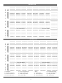
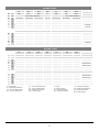
3. HEAT OUTPUT DATA
PT Qw Δpw Tp2 PT Qw Δpw Tp2
Tp1 V kW l/h kPa °C kW l/h kPa °C
°C m
3
/h Tw1 / Tw2 = 90/70
o
C Tw1 / Tw2 = 80/60
o
C
0
2200/2500/2600
12,6/13,5/13,8 558/597/609 1,9/2,2/2,3 17,0/16,0/15,5 10,6/11,3/11,5 465/497/507 1,4/1,6/1,7 14,0/13,5/13,0
5
11,8/12,6/12,8 519/555/566 1,7/1,9/2,0 21,0/20,0/19,5 9,7/10,4/10,6 426/455/464 1,2/1,3/1,4 18,0/17,5/17,0
10
10,9/11,6/11,9 480/513/524 1,5/1,6/1,7 24,5/23,5/24,5 8,8/9,4/9 386/413/395 1,0/1,1/1,1 21,5/21,0/21,5
15
10,0/10,7/10,9 441/471/481 1,3/1,4/1,5 28,0/27,5/27,0 7,9/8,5/8,6 347/370/378 0,8/0,9/1,0 25,5/25,0/24,5
20
9,1/9,7/9,9 402/429/438 1,1/1,2/1,2 32,0/31,5/31,0 7,0/7,5/7,6 306/328/334 0,7/0,8/0,8 29,5/29,0/28,5
Tw1 / Tw2 = 70/50
o
C Tw1 / Tw2 = 70/40
o
C
0
2200/2500/2600
8,5/9,0/9,2 370/396/404 1,0/1,1/1,2 11,5/11,0/10,5 5,3/5,8/5,9 153/168/172 0,2/0,2/0,3 7,0/6,5/6,5
5
7,5/8,1/8,2 330/353/360 0,7/0,8/0,9 15,0/14,5/14,0 2,8/2,9/2,9 83/85/86 0,1/0,1/0,1 9,0/8,5/8,5
10
6,6/7,1/7,2 290/310/316 0,6/0,6/0,7 19,0/18,5/18,0 2,5/2,5/2,6 72/74/75 0,1/0,1/0,1 13,5/13,0/12,5
15
5,7/6,1/6,2 248/266/271 0,5/0,5/0,6 22,5/22,0/21,5 2,1/2,2/2,2 62/63/64 0,1/0,1/0,1 18,0/17,5/17,5
20
4,7/5,0/5,1 204/220/225 0,3/0,4/0,4 26,0/25,5/25,0 1,8/1,8/1,8 51/53/53 0,1/0,1/0,1 22,5/22,0/22,0
Tw1 / Tw2 = 60/40
o
C Tw1 / Tw2 = 50/40
o
C
0
2200/2500/2600
6,2/6,6/6,8 269/289/295 0,6/0,6/0,7 8,5/8,0/7,5 6,8/7,3/7,5 594/636/649 2,4/2,7/2,8 9,5/9,0/8,5
5
5,2/5,6/5,7 226/243/249 0,4/0,4/0,5 12,0/12,0/11,5 5,9/6,3/6,5 514/550/562 1,9/2,1/2,2 13,0/12,5/12,5
10
4,1/4,5/4,6 178/193/198 0,3/0,3/0,3 15,5/15,0/15,0 5,0/5,3/5,6 434/464/474 1,4/1,5/1,6 17,0/16,5/16,0
15
2,0/2,1/2,1 88/90/91 0,1/0,1/0,1 18,0/17,5/17,5 4,0/4,3/4,4 352/377/385 0,9/1,1/1,1 20,5/20,0/20,0
20
1,6/1,7/1,7 72/74/74 0,1/0,1/0,1 22,5/22,0/22,0 3,1/3,3/3,4 266/285/292 0,6/0,6/0,7 24,5/24,0/24,0
MU-EMP-10-W; MU-EMP-15-W; MU-EMP-20-W
MU-EMP-10-W2F; MU-EMP-15-W2F; MU-EMP-20-W2F
MU-EMP-10/8-R3; MU-EMP-15/12-R3; MU-EMP-20/16-R3
MU-EMP-10-A; MU-EMP-15-A; MU-EMP-20-A
MU-EMP-10-W
V - Air flow
PT - Heating capacity
Tp1 - Inlet air temperature
Tp2 - Outlet air temperature
Tw1 - Inlet water temperature
Tw2 - Outlet water temperature
Qw - Heating water stream
pw - water pressure
Δ
6
6,0
5,5
5,0
4,5
4,0
3,5
2.5. VELOC. DE CAUDAL DE AIRE
3. TABLAS DE CAPACIDAD CALORÍFICA
V - Caudal de aire
PT - Capacidad de calefacción
Tp1 - Temp. de entrada de aire
Tp2 - Temp. de salida de aire
Tw1 - Temp. de entrada de agua
Tw2 - Temp. de salida de agua
Qw - Caudal de agua caliente
Δ pw - presión de agua

PT Qw Δpw Tp2 PT Qw Δpw
Tp2
Tp1 V kW l/h kPa °C kW l/h kPa
°C
°C m
3
/h
Tw1 / Tw2 = 90/70
o
C
Tw1 / Tw2 = 80/60
o
C
0
3200/3500/4000
20,9/21,9/23,5 923/968/1039 5,9/6,5/7,4 19,6/18,5/17,5 17,8/18,7/20,0 783/821/881 4,5/4,9/5,6 16,5/16,0/15,0
5
19,6/20,5/22,0 863/905/972 5,3/5,6/6,6 23,0/22,5/21,5 16,4/17,3/18,5 722/758/813 3,9/4,3/4,9 20,0/19,5/18,5
10
18,2/19,1/20,5 803/842/904 4,6/5,0/5,7 27,0/26,0/25,0 15,0/15,8/17,0 662/694/745 3,3/3,6/4,1 24,0/23,0/22,5
15
16,8/17,6/19,0 742/779/835 4,0/4,4/5,0 30,5/30,0/30,0 13,7/14,3/15,4 601/630/676 2,8/3,0/3,5 27,5/27,0/26,5
20
15,5/16,2/17,4 682/715/767 3,4/3,7/4,2 34,0/33,5/32,5 12,3/12,9/13,8 539/566/607 2,3/2,5/2,8 31,0/30,5/30,0
Tw1 / Tw2 = 70/50
o
C
Tw1 / Tw2 = 70/40
o
C
0
3200/3500/4000
14,7/15,4/16,5 642/674/723 3,3/3,6/4,0 13,5/13,0/12,5 11,5/12,1/13,0 335/352/378 1,0/1,1/1,3 10,5/10,0/9,6
5
13,3/13,9/15,0 581/610/655 2,7/3,0/3,4 17,5/16,5/16,0 10,1/10,5/11,3 293/307/330 0,8/0,9/1,0 14,5/14,0/13,5
10
11,9/12,5/13,4 520/546/585 2,2/2,4/2,8 21,0/20,5/20,0 8,6/9,0/9,7 249/262/281 0,6/0,7/0,8 18,0/17,5
/
17,0
15
10,5/11,0/11,78 458/481/516 1,8/1,9/2,2 24,5/24,0/23,5 7,0/7,3/7,9 202/213/230 0,4/0,5/0,5 21,5/21,0/20,5
20
9,0/9,5/10,2 395/415/445 1,4/1,5/1,7 28,0/27,5/27,5 5,1/5,4/6,0 147/158/173 0,2/0,3/0,3 24,5/24,5/24,0
Tw1 / Tw2 = 60/40
o
C
Tw1 / Tw2 = 50/40
o
C
0
3200/3500/4000
11,5/12,0/13,0 500/525/563 2,2/2,4/2,7 10,5/10,0/9,5 11,5/12,0/13,0 1001/1050/1128 7,7/8,4/9,5 10,5/10,0/9,5
5
10,1/10,5/11,5 438/460/494 1,7/1,9/2,1 14,5/14,0/13,5 10,1/10,6/11,4 878/922/990 6,1/6,6/7,5 14,5/14,0/13,5
10
8,6/9,0/9,7 375/394/423 1,3/1,4/1,6 18,0/17,5/17,0 8,7/9,1/9,8 755/793/851 4,6/5,0/5,7
18,0
/17,5/17,0
15
7,1/7,5/8,1 311/327/351 0,9/1,0/1,1 21,5/21,0/21,0 7,3/7,6/8,2 631/662/711 3,3/3,6/4,1 21,5/21,5/21,0
20
5,6/5,9/6,3 243/256/276 0,6/0,7/0,7 25,0/24,5/24,5 5,8/6,1/6,5 505/530/568 2,2/2,4/2,8 25,5/25,0/24,5
PT Qw Δpw Tp2 PT Qw Δpw Tp2
Tp1 V kW l/h kPa °C kW l/h kPa °C
°C m
3
/h
Tw1 / Tw2 = 90/70
o
C
Tw1 / Tw2 = 80/60
o
C
0
4000/4300/5200
27,6/28,7/31,8 1217/1266/1402 11,4/12,2/14,7 20,5/19,5/18,0 23,6/24,6/27,7 1038/1080/1195 8,7/9,4/11,3 17,5/17,0/15,5
5
25,8/26,9/29,7 1140/1186/1312 10,0/10,8/13,0 24,0/23,5/22,0 21,9/22,7/25,2 961/999/1106 7,6/8,2/9,8 21,1/20,5/19,5
10
24,0/25,0/27,7 1063/1105/1223 8,9/9,5/11,5 27,5/27,0/25,7 20,1/20,9/23,1 883/918/1016 6,5/7,0/8,4 25,0/24,5/22,5
15
22,3/23,2/25,7 985/1024/1133 7,7/8,3/10,0 32,5/30,5/29,5 18,3/19,0/21,0 804/836/925 5,5/5,9/7,1 28,5/28,0/27,0
20
20,5/21,4/23,6 907/943/1043 6,6/7,1/8,8 35,0/34,5/33,0 16,5/17,2/19,0 725/754/834 4,6/4,9/5,9 32,0/31,5/30,5
Tw1 / Tw2 = 70/50
o
C Tw1 / Tw2 = 70/40
o
C
0
4000/4300/5200
19,7/20,5/22,5 860/894/990 6,4/6,9/8,3 14,5/14,0/13,0 16,1/16,7/18,5 468/487/538 2,2/2,3/2,8 12,0/11,5/10,5
5
17,9/18,6/20,5 782/813/900 5,4/5,8/6,9 18,0/17,5/17,0 14,3/14,8/16,4 414/431/477 1,8/1,9/2,3 15,5/15,0/14,5
10
16,1/16,7/18,5 703/731/809 4,5/4,7/5,7 21,5/21,5/20,5 12,4/12,9/14,2 360/374/414 1,4/1,5/1,8 19,0/19,0/18,0
15
14,5/14,8/16,4 624/649/717 3,6/3,8/4,6 25,5/25,0/24,5 10,4/10,9/12,0 304/316/350 1,0/1,1/1,3 22,5/22,5/21,5
20
12,4/12,9/14,3 544/565/625 2,8/3,0/3,6 29,0/28,5/28,0 8,4/8,8/9,6 245/256/284 0,7/0,7/0,9 26,0/26,0/25,5
Tw1 / Tw2 = 60/40
o
C Tw1 / Tw2 = 50/40
o
C
0
4000/4300/5200
15,6/16,3/18,0 681/708/784 4,6/4,7/5,6 11,5/11,0/10,5 15,3/15,9/17,6 1327/1380/1529 14,8/15,9/19,2 11,5/11,0/10,0
5
13,8/14,4/15,9 602/626/693 3,5/3,7/4,5 15,0/15,0/14,0 13,5/14,0/15,5 1170/1217/1348 11,8/12,7/15,2 15,0/14,5/13,5
10
12,0/12,5/13,8 522/543/601 2,7/2,9/3,5 18,5/18,5/18,0 11,6/12,1/13,4 1012/1052/1165 9,1/9,7/11,7 18,5/18,5/17,5
15
10,1/10,5/11,6 441/458/507 2,0/2,1/2,6 22,5/22,0/21,5 9,8/10,2/11,3 852/886/981 6,6/7,1/8,6 22,5/22,0/21,5
20
8,2/8,5/9,5 357/372/412 1,4/1,5/1,8 26,0/25,5/25,0 7,9/8,3/9,1 690/718/794 4,6/4,9/5,6 25,5/25,5/25,0
MU-EMP-15-W
MU-EMP-20-W
7
V - Air flow
PT - Heating capacity
Tp1 - Inlet air temperature
Tp2 - Outlet air temperature
Tw1 - Inlet water temperature
Tw2 - Outlet water temperature
Qw - Heating water stream
pw - water pressure
Δ
V - Caudal de aire
PT - Capacidad de calefacción
Tp1 - Temp. de entrada de aire
Tp2 - Temp. de salida de aire
Tw1 - Temp. de entrada de agua
Tw2 - Temp. de salida de agua
Qw - Caudal de agua caliente
Δ pw - presión de agua

PT Qw Δpw Tp2 PT Qw Δpw
Tp2
Tp1 V kW l/h kPa °C kW l/h kPa
°C
°C m
3
/h
Tw1 / Tw2 = 90/70
o
C
Tw1 / Tw2 = 80/60
o
C
0
2000/2300/2400
22,0/23,9/24,5 970/1053/1080 1,49/1,74/1,82 33/31/30 18,9/20,0/20,5 832/878/900 1,16/1,28/1,34
27/26/25
5
20,4/22,2/22,8 902/980/1004 1,31/1,52/1,59 35/34/33 17,3/18,3/18,8 761/803/824 0,99/1,09/1,14
29/28/28
10
18,9/20,5/21,0 834/906/928 1,13/1,32/1,38 38/36/36 15,7/16,6/17,0 691/729/747 0,83/0,91/0,95
32/31/31
15
17,4/18,8/19.3 766/832/852 0,97/1,13/1,18 40/39/39 14,1/14,9/15,3 619/654/670 0,68/0,75/0,78
35/34/34
20
15,8/17,2/17,6 697/757/776 0,82/0,95/0,99 43/42/41 12,5/13,1/13,5 547/578/592 0,54/0,6/0,63
37/37/36
Tw1 / Tw2 = 70/50
o
C Tw1 / Tw2 = 70/40
o
C
0
2000/2300/2400
15,1/13,5/11,8 662/699/716 0,79/0,87/0,91
21/21/20
10,7/11,6/12,0 464/508/521 0,43/0,51/0,53 16/15/15
5
13,5/14,2/14,6 590/623/639 0,64/0,71/0,74 24/23/23 8,8/9,7/10,0 386/424/436 0,31/0,37/0,39
18/18/17
10
11,8/12,5/12,8 517/546/560 0,51/0,56/0,58 27/26/26 6,6/7,6/7,8 289/329/341 0,19/0,23/0,25
20/19/20
15
10,1/10,7/11,0 441/467/479 0,38/0,42/0,44 29/29/28 3,8/4,0/4,0 167/173/174 0,07/0,08/0,08
21/20/21
20
8,3/8,8/9,0 362/384/395 0,27/0,3/0,31 31/31/31 3,1/3,2/3,3 137/141/142 0,05/0,05/0,05
25/24/24
PT Qw Δpw Tp2 PT Qw Δpw
Tp2
Tp1 V kW l/h kPa °C kW l/h kPa
°C
°C m
3
/h
Tw1 / Tw2 = 90/70
o
C
Tw1 / Tw2 = 80/60
o
C
0
3000/3200/3800
36,6/38,1/42,2 1615/1680/1863 4,7/5,0/6,1 36,0/35,0/33,0 31,2/32,5/36,0 1370/1425/1580 3,6/3,8/4,6
31,0/30,0/28,0
5
34,2/35,6/39,4 1509/1570/1740 4,1/4,4/5,4 38,5/38,0/35,5 28,8/29,9/33,2 1264/1314/1457 3,1/3,3/4,0
33,5/32,5/31,0
10
31,8/33,1/39,4 1403/1460/1618 3,6/3,9/4,7 41,0/40,5/38,5 26,3/27,4/30,4 1157/1203/1334 2,6/2,8/3,4
36,0/35,0/33,5
15
29,4/30,6/33,9 1297/1349/1495 3,1/3,4/4,1 43,5/43,0/41,0 23,9/24,9/27,5 1050/1092/1210 2,2/2,4/2,8
38.5/37,5/36,0
20
27,0/28,1/31,1 1191/1239/1373 2,7/2,9/3,5 46,0/45,5/44,0 21,5/22,3/24,7 943/981/1086 1,8/1,9/2,3
41,0/40,0/39,0
Tw1 / Tw2 = 70/50
o
C Tw1 / Tw2 = 70/40
o
C
0
3000/3200/3800
25,7/26,7/29,6 1125/1170/1296 2,6/2,8/3,3 25,5/24,5/23,0 20,1/20,9/23,2 876/911/1010 1,7/1,8/2,2
20,0/19,5/18,0
5
23,2/24,2/26,8 1018/1058/1173 2,1/2,3/2,8 28,0/27,5/26,0 17,6/18,3/20,3 767/798/885 1,3/1,4/1,7
22,5/22,0/21,0
10
20,8/21,6/24,0 910/946/1049 1,7/1,9/2,3 30,5/30,0/28,5 15,1/15,7/17,4 656/683/758 1,0/1,1/1,3
25,0/24,5/23,5
15
18,3/19,1/21,1 801/833/924 1,4/1,5/1,8 33,0/32,5/31,5 12,4/13,0/14,4 542/565/628 0,7/0,8/0,9
27,0/27,0/26,0
20
18,3/19,1/21,1 801/833/924 1,4/1,5/1,8 33,0/32,5/31,5 9,66/10,1/11/3 421/440/492 0,5/0,5/0,6
29,5/29,0/28,5
MU-EMP-10-W2F
MU-EMP-15-W2F
8
V - Air flow
PT - Heating capacity
Tp1 - Inlet air temperature
Tp2 - Outlet air temperature
Tw1 - Inlet water temperature
Tw2 - Outlet water temperature
Qw - Heating water stream
pw - water pressure
Δ
V - Caudal de aire
PT - Capacidad de calefacción
Tp1 - Temp. de entrada de aire
Tp2 - Temp. de salida de aire
Tw1 - Temp. de entrada de agua
Tw2 - Temp. de salida de agua
Qw - Caudal de agua caliente
Δ pw - presión de agua

PT Qw Δpw Tp2 PT Qw Δpw
Tp2
Tp1 V kW l/h kPa °C kW l/h kPa
°C
°C m
3
/h
Tw1 / Tw2 = 90/70
o
C
Tw1 / Tw2 = 80/60
o
C
0
3800/3900/4900
48,4/50,7/57,2 2135/2238/2524 8,98/9,79/12,2 38/37/34 41,5/43,5/49,0 1822/1910/2153 6,91/7,52/9,37
32/31/29
5
45,3/47,5/53,5 1999/2095/2362 7,96/8,57/10,8 40/39/37 38,3/40,2/45,3 1685/1766/1991 5,99/6,52/8,12
35/34/32
10
42,2/44,2/49,9 1862/1951/2200 6,99/7,62/9,49 43/42/39 35,2/36,9/41,6 1547/1622/1828 5,13/5,58/6,95
37/36/34
15
39,1/41,0/46,2 1725/1808/2038 6,08/6,62/8,25 45/44/42 32,1/33,6/37,9 1409/1477/1664 4,33/4,71/5,86
40/39/37
20
36,0/37,7/42,5 1588/1664/1876 5,23/5,69/7,09 48/47/45 28,9/30,3/34,2 1271/1332/1501 3,59/3,9/4,85
42/41/40
Tw1 / Tw2 = 70/50
o
C Tw1 / Tw2 = 70/40
o
C
0
34,5/36,2/40,8 1510/1582/1783 5.06/5,51/6,85 27/26/24 27,4/28,8/32,4 1196/1523/1413 3,44/3,74/4,64
21/21/19
5
31,4/32,9/37,1 1372/1437/1620 4,25/4,63/5,75 29/29/27 24,2/25,4/28,6 1057/1107/1248 2,75/2,99/3,71
24/23/22
10
28,2/29,5/33,3 1233/1292/1456 3,51/3,82/4,74 32/31/30 21,0/22,0/24,8 916/960/1082 2,13/2,32/2,87
26/26/25
15
25,0/26,2/29,5 1094/1146/999 2,83/3,07/3,81 34/34/32 17,7/18,6/21,0 773/810/913 1,57/1,71/2,12
29/28/27
20
21,8/22,8/25,7 953/999/1125 2,21/2,4/2,97 37/36/35 14,4/15,1/17,0 626/657/741 1,08/1,18/1,46
31/31/30
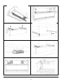
4. INSTALATION
1.
B A
572 mm 1024 mm
572 mm 1510 mm
572 mm 2000 mm
2.
C D E F
133 770 mm 121 mm 561 mm
182 1207 mm 122 mm 561 mm
256 1621 mm 123 mm 561 mm
3
.
4.
MU-EMP-20-W2F
MU-EMP-10-...
MU-EMP-15-...
MU-EMP-20-...
MU-EMP-10-...
MU-EMP-15-...
MU-EMP-20-...
9
3800/3900/4900
V - Air flow
PT - Heating capacity
Tp1 - Inlet air temperature
Tp2 - Outlet air temperature
Tw1 - Inlet water temperature
Tw2 - Outlet water temperature
Qw - Heating water stream
pw - water pressure
Δ
V - Caudal de aire
PT - Capacidad de calefacción
Tp1 - Temp. de entrada de aire
Tp2 - Temp. de salida de aire
Tw1 - Temp. de entrada de agua
Tw2 - Temp. de salida de agua
Qw - Caudal de agua caliente
Δ pw - presión de agua
4. INSTALACIÓN

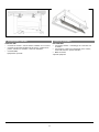
5.
6.
7.
8.
9. 10.
11.
12.
10

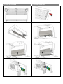
13. 14.
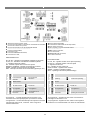
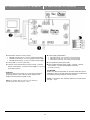
DRV CONTROL:
Connecting curtains – controlling up to 5 units with one
controller;
Connecting to curtain room thermostat*, door contact*,
valves with actuator*, speed controller*;
BMS connection;
*optional equipment
5. CONTROL SYSTEMS
11
5. SISTEMAS DE CONTROL
CONTROL DRV:
ႛ Conexión de cortinas - controla hasta 5 unidades con un control;
ႛ Conexión al termostato ambiente de la cortina*, contacto de la
puerta*, válvulas con actuador*, control de velocidad*;
ႛ Conexión BMS;
equipamiento opcional*

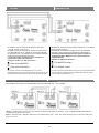
5.1. CONNECTING GUIDE
1.
2.
3.
4.
5.
6.
7.
8.
MU-EMP-R3
MU-EMP-A/W/W2F
12
5.1. GUÍA DE CONEXIÓN

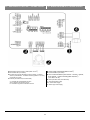
n Power supply 230V/50Hz;
o Connectors for thermostat and fan step switch;
p Door contact connector;
q
Valve actuator connector MU-EMP-W/W2F heaters contactor
connector MU-EMP-R3;
r BMS system connection;
s T-box connectors
;
t MASTER-SLAVE connectors;
u PT-1000 connectors;
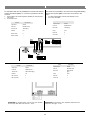
LED INDICATORS:
G1, G2, G3
– signalize number of fan speed operating
S1, S2, S3
– signalize number of set fan speed
T
– signalize of valve set
DC
– signalize of door contact set
OPEN, CLOSE
– signalize valve actuator
WORK
–
signalize of software working
SW3
– operating mode switch (default settings)
*K1 program
me –
Signal from door switch or thermostat is
main signal
for the device to run
**K2 program
me – Signal from door switch is
main signal
for
the device to run and thermostat is in charge of valve/heaters
1
2
MASTER mode
operating
SLAVE mode operating
3
Service
4
5
K1 Programme*
K2 Programme**
6
Operating with
thermostat
Operating w/o thermostat
5.2. DRV-EMP CONTROL SYSTEM
MU-EMP-A/W/W2F
MU-EMP-R3
13
5.2. SISTEMA DE CONTROL DRV-EMP
1
2
3
4
5
6
MU-EMP-A/W/W2F
MU-EMP-R3
*Programa K1 – La señal del interruptor de la puerta o del
termostato es la señal principal para que funcione la unidad.
**Programa K2 – La señal del interruptor de la puerta es la señal
principal para activar la ud., el termost. está a cargo de la
válvula/ resistencias.
Funcionamiento
MASTER
Funcionamiento
ESCLAVO
Mantenimiento
K1 Programa* K2 Programa**
Funcionamiento con
termostato
Funcionamiento sin
termostato
n
o
p
q
r
s
t
u
INDICADORES LED:
G1, G2, G3 – señaliza la velocidad del ventilador en funcionan.
S1, S2, S3 – señaliza la velocidad del ventilador ajustada
T – señaliza el ajuste de válvula
DC - señaliza el ajuste del contacto de la puerta
ABIERTA, CERRADA - señaliza el actuador de la válvula
WORK - señaliza el funcionamiento del software
SW3 - Interruptor del modo de funcionamiento (ajustes por def.)
Alimentación eléctrica 230V / 50Hz;
Conector para termostato e interruptor de velocidades del ventilador;
Conector de contacto de la puerta;
Conector del actuador de la válvula MU-EMP-W/W2F
contacto de las resistencias MU-EMP-R3;
Conexión a sistema BMS;
Conectores T-box;
Conectores MÁSTER-ESCLAVOS;
Conectores PT-1000;

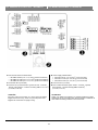
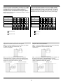
n Power supply 230V/50Hz (OMY 3x1mm
2
)
o
p
Door contact DCe/DCm (door closed
– contacts opened;
door opened – contacts closed) (OMY 2x0,5mm
2
)
q
A
– Exchanger water supply
AB
– Valve water supply
B
–
Return pipe water supply
5.2.1. WIRING DIAGRAM SE-3 + MU-EMP-A/W/W2F
32 14 7 6 5
Low
Med
Hig
Valve (CO13251-252; CO13254-255)
Thermostat SE-3 (CO14653)
(CL91188; CL91190)
14
5.2.1. ESQUEMA ELÉCTRICO SE-3 + MU-EMP-A/W/W2F
Alimentación eléctrica 230 V/ 50Hz (OMY 3x1mm
2
)
Termostato SE-3 (CO14653)
Contacto de la puerta DCe/DCm (puerta cerrada - contactos
abierto; puerta abierta - contactos cerrados) (OMY 2 x 0,5 mm
2
)
(CL91188; CL91190)
Válvula (CO13251-252; CO13254-255)
A - Entrada del intercambiador de agua
AB - Entrada de la válvula de agua
B - Entrada de agua de la tubería de retorno
n
o
p
q

Power supply 3x400V/50Hz
x MU-EMP-10/8-R3 (min. 5x2,5 mm
2
) (Overcurrent B16)
x
(min. 5x4,0 mm
2
) (Overcurrent B20)
x (min. 5x4,0 mm
2
) (Overcurrent B25)
ATTENTION:
Switch 4 on S
W3 to the position “E”
and then restart the system
switching it off for 5 seconds. Each time the device is switched off
the heaters are being cooled for next
30
seconds
5.2.2. WIRING DIAGRAM SE-3 + MU-EMP-R3
n
o
p Door contact DCe/DCm (door closed – contacts opened;
door opened – contacts closed) (OMY 2x0,5mm
2
)
Thermostat SE-3 (CO14653)
(CL91188; CL91190)
32 14 7 6 5
Low
Med
Hig
MU-EMP-15/12-R3
MU-EMP-20/16-R3
15
5.2.2. ESQUEMA ELÉCTRICO SE-3 + MU-EMP-R3
Alimentación eléctrica 3x400V/50Hz
MU-EMP-10/8-R3 (mín. 5 x 2,5 mm
2
) (Sobrecorriente B16)
MU-EMP-15/12-R3 (mín. 5 x 4,0 mm
2
) (Sobrecorriente B20)
MU-EMP-20/16-R3 (mín. 5 x 4,0 mm
2
) (Sobrecorriente B25)
Termostato SE-3 (CO14653)
Contacto de la puerta DCe/DCm (puerta cerrada - contactos
abierto; puerta abierta - contactos cerrados) (OMY 2 x 0,5 mm
2
)
(CL91188; CL91190)
ATENCIÓN:
Conecte 4 a SW3 en la posición "E" y luego reinicie el sistema
apagándolo durante 5 seg. Cada vez que el dispositivo está
apagado las resistencias se apagan 30 seg.
n
o
p

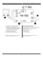
NOTE : In last DRV in line, dipswitch SW2 has to be
switched to the right – T120.
5.2.3. WIRING DIAGRAM T-box + MU-EMP-A/W/W2F
n Power supply 230V/50Hz (OMY 3x1mm
2
)
p Door contact DCe/DCm (door closed – contacts opened;
door opened
–
contacts closed) (OMY 2x0,5mm
2
)
q
A
– Exchanger water supply
AB
– Valve water supply
B
– Return pipe water supply
Valve (CO13251-252; CO13254-255)
(CL91188; CL91190)
T-box (OMY 4x0,5mm
2
) (CL91182)
o
16
5.2.3. ESQUEMA ELÉCTRICO T-box + MU-EMP-A/W/W2F
Alimentación eléctrica 230 V/ 50Hz (OMY 3x1mm
2
)
T-box (OMY 4 x 0,5 mm
2
) (CL91182)
Contacto de la puerta DCe/DCm (puerta cerrada -
contactos abierto; puerta abierta - contactos
cerrados) (OMY 2 x 0,5 mm
2
) (CL91188; CL91190)
Válvula (CO13251-252; CO13254-255)
A - Entrada del intercambiador de agua
AB - Entrada de la válvula de agua
B - Entrada de agua de la tubería de retorno
NOTA : En el último DRV en línea, hay que cambiar
el interruptor DIP SW2 a la derecha - T120.
n
p
q
o

T-box (OMY 4x0,5mm
2
) (CL91182)
ATTENTION:
Switch 4 on SW3 to the position “E” and then restart the system
switching it off for 5 seconds. Each time the device is switched off
the heaters are being cooled for next 30 seconds.
NOTE : In last DRV in line, dipswitch SW2 has to be switched to
the right – T120.
5.2.4. WIRING DIAGRAM T-box + MU-EMP-R3
Power supply 3x400V/50Hz
x MU-EMP-10/8-R3 (min. 5x2,5 mm
2
) (Overcurrent B16)
x
(min. 5x4,0
mm
2
) (Overcurrent B20)
x (min. 5x4,0 mm
2
) (Overcurrent B25)
n
o
p Door contact DCe/DCm (door closed – contacts opened;
door opened – contacts closed) (OMY 2x0,5mm
2
)
(CL91188; CL91190)
MU-EMP-15/12-R3
MU-EMP-20/16-R3
17
5.2.4. ESQUEMA ELÉCTRICO T-box + MU-EMP-R3
Alimentación eléctrica 3 x 400 V/ 50 Hz
MU-EMP-10/8-R3 (mín. 5 x 2,5 mm
2
) (Sobrecorriente B16)
MU-EMP-15/12-R3 (mín. 5 x 4,0 mm
2
) (Sobrecorriente B20)
MU-EMP-20/16-R3 (mín. 5 x 4,0 mm
2
) (Sobrecorriente B25)
T-box (OMY 4 x 0,5 mm
2
) (CL91182)
Contacto de la puerta DCe/DCm (puerta cerrada - contactos
abierto; puerta abierta - contactos cerrados) (OMY 2 x 0,5 mm
2
)
(CL91188; CL91190)
ATENCIÓN:
Conecte 4 a SW3 en la posición "E" y luego reinicie el sistema
apagándolo durante 5 seg. Cada vez que el dispositivo está
apagado las resistencias se apagan 30 seg.
NOTA : En el último DRV en línea, hay que cambiar el
interruptor DIP SW2 a la derecha - T120.
n
o
p

Electrical air curtain chaining provides control from 1 to 5 devices
using one SE-3
and DC.
Electrical air curtain chaining might be done by cable OMY
3x0,5mm
2
using connectors CURTAIN IN; CURTAIN OUT
Connecting units among themselves ensur
e transfer of
controlling signals. Whatever each curtain need to be
supplied directly.
Switch 2 on SW3 set In position:
– For MASTER curtain
–
For SLAVE curtain
In case t
o connect several devices to one T-
box and independent
(
local ) work of curtains with door switches use DRV IN ; DRV
OUT connectors (Section 5.3.7 )
It is possible to connect up to 31modules DRV and control them with one T- box controller.
NOTE: In last DRV in line, dipswitch SW2 has to be switched to the right – T120. The maximum length of the connecting cable 50 m
(
LIYCY 3x 0,5 mm
2
).
5.2.5. CONTROL SYSTEM – MASTER-SLAVE
COMMUNICATION
5.2.6. CONTROL SYSTEM – DRV CHAINING
18
5.2.5. SISTEMA DE CONTROL - COMUNICACIÓN MÁSTER -
ESCLAVA
El sistema en red de cortina de aire eléctrica controla de
1 a 5 uds. usando un SE-3 y DC.
El sistema en red de cortina de aire eléctrica se podría hacer
con cable OMY 3x0, 5mm
2
usando los conectores CURTAIN
IN; CURTAIN OUT. Las unidades entre-conectadas garantizan
la transferencia de las señales de control.
Lo que cada cortina necesita que se le suministre la
alimentación eléctrica directamente.
Configurar el DIP 2 en SW3 en posición:
Para cortina MASTER
Para cortina ESCLAVA
En caso de conectar varios dispositivos a una T-box e
independiente (local). El funcionamiento de las cortinas con los
interruptores de las puertas usa los conectores DRV IN, DRV
–
–
5.2.6. SISTEMA DE CONTROL - CADENA DRV
Es posible conectar hasta 31 módulo DRV y controlarlos con un control T-box.
NOTA: En el último DRV en línea, hay que cambiar el interruptor DIP SW2 a la derecha - T120. La longitud máxima del cable de
conexión 50 m (LIYCY 3x 0,5 mm
2
).

DRV driver has a possibility to be connected to integrated Building
Management System (BMS). Connection can be done in two
ways:
1. To DRV pcb board(in case of work without T-box)
2. To T-box controller
Name
Description
`Physical layer
RS485
Protocol
MODBUS
-
RTU
Baud rate
38400
[bps]
Parity
Even
Data bits
8
STOP bits
1
ATTENTION
: In last DRV in line, dipswitch SW2 has to be
switched to the right
– T120.
5.2.7. CONTROL SYSTEM – BMS CONNECTION
19
5.2.7. SISTEMA DE CONTROL - CONEXIÓN BMS
El controlador DRV tiene la posibilidad de conectarse al Sistema
Gestión de Edificios (BMS). La conexión se puede hacer de dos
maneras:
1. Para la placa de circuito impreso de DRV (en caso de func.
sin T-box)
2. Al control T-box
ATENCIÓN: En el último DRV en línea, hay que cambiar
el interruptor DIP SW2 a la derecha - T120.
Capa física RS485
Protocolo MODBUS-RTU
Tasa de bits 38400 [bps]
Paridad Par
Bits de datos 8
Bits de parada 1
Nombre Descripción
Name
Description
Physical layer
RS485
Protocol
MODBUS-RTU
Baud rate
9600-230400
[bps]
Parity
Even
Data bits
8
STOP bits
1
Capa física RS485
Protocolo MODBUS-RTU
Tasa de bits 9600-230400 [bps]
Paridad
Bits de datos 8
Bits de parada 1
Nombre Descripción
Par

When connecting DRV modules to the T-box controller or BMS,
you have to binary set addresses on each (each DRV must have
individual address) DRV module by DIP
-
switch SW1. To address
modules check if the power supply is turned off, than set then the
addresses as shown in the table, than turn on the power supply .
switch down
switch up
Addresses DRV
1
2
3
…
31
1 2 3 4 5 6
1 2 4 8 16 Y1
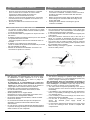
6. DOOR CONTACT INSTALLATION
Sample of door contact installation.
DCm – In case of installation in way which is show on drawing
below, connectors 21 and 22 need to be used.
Hinged doors
Dce – In the case of sliding doors (with a parallel installation of
the sensor and magnet ) is required distance 9-12 mm
between the sensor housing and the magnet. For Hinged door
max 8 mm between housing and magnet.
Hinged door
Sliding doors
5.2.8. CONTROL SYSTEM – SETTING BMS ADDRESS
20
5.2.8. SISTEMA DE CONTROL - AJUSTE DE DIRECCIONES BMS
Cuando se conectan módulos DRV al controlador T-box o BMS,
se deben establecer direcciones binarias en cada módulo DRV
(cada DRV debe tener dirección individual) mediante el
interruptor DIP SW1. Para asignar direcciones a los módulos
compruebe si la fuente de alimentación está apagada, que fija
después las direcciones como se muestra en la tabla, y enciende
la fuente de alimentación.
1
2
3
…
31
1 2 3 4 5 6
1 2 4 8 16 Y1
Direcciones DRV
interruptor abajo
interruptor arriba
6. INSTALACIÓN DEL CONTACTO DE LA
PUERTA
Ejemplo de instalación del contacto de la puerta.
DCm - En caso de instalarse como se muestra en la figura,
se tienen que usar los conectores 21 y 22.
Puertas con bisagras
Dce - En el caso de puertas correderas (con instalación
paralela del sensor y el imán) se requiere una distancia de 9-
12 mm entre la carcasa del sensor y el imán. Para puerta con
bisagra máx. 8 mm entre la carcasa y el imán.
Puertas con bisagras Puertas correderas

7. GUIDELINES FOR CONNECTION WITH POWER
SUPPLY
Before connecting the power supply check the
correctness of controllers connection. These connections
should be executed in accordance with their technical
documentation.
Before connecting the power supply check whether the
mains voltage is in accordance with the voltage on the
device data shield.
Starting the device without connecting the ground
conductor is forbidden.
LINE
8. GUIDELINES FOR CONNECTION WITH PIPELINE
The connection should be executed in a way which does
not induce stresses. It is recommended to use flexible pipes
to deliver heating agent to the exchanger.
It is recommended to install vent valves at the highest point
of the system.
The system should be executed so that, in the case of a
failure, it is possible to disassemble the device. For this
purpose it is best to use shut-off valves just by the device.
The system with the heating medium must be protected
against an increase of the heating medium pressure above
the permissible value (1.6 MPa).
While screwing exchanger to pipeline - connecting stubs
has to be hold by wrench.
9. OPERATION
The device is designed for operation inside buildings, at
temperatures above 0
o
C. In low temperatures (below 0ºC)
there is a danger of freezing of the medium.
The manufacturer bears no responsibility for damage of
the heat exchanger resulting from freezing of the medium
in the exchanger. It is forbidden to place any objects on the
heater or to hang any objects on the connecting stubs.
The device must be inspected periodically. In the case of
incorrect operation of the device it should be switched off
immediately.
It is forbidden to use a damaged device. The manufacturer
bears no responsibility for damage resulting from the use
of a damaged device.
If it is necessary to clean the exchanger, be careful not to
damage the aluminium lamellas.
For the time of performing inspection or cleaning the
device, the electrical power supply should be
disconnected.
In case water is drained from the device for a longer period
of time, the exchanger tubes should be emptied with
compressed air
21
ႛ Antes de conectar la fuente de alimentación comprobar
que la conexión de los controles es correcta. Estas
conexiones se deben realizar de acuerdo a lo
especificado en la documentación técnica.
ႛ Antes de conectar la fuente de alimentación, compruebe
si la tensión de la red es compatible con la tensión en la
etiqueta del fabricante.
ႛ Encender la unidad sin la conexión a tierra está
prohibido
7. GUÍA PARA CONEXIÓN C/ ALIMENTAC.
ELÉCT.
8. GUÍA PARA CONEXIÓN CON TUBERÍA
ႛ La conexión se debe realizar de manera que no quede
tensada. Se recomienda utilizar tuberías flexibles expulsar
el calor al intercambiador.
ႛ Se recomienda instalar los purgadores en el punto más alto
del sistema.
ႛ El sistema se debe encender de manera que en caso de fallo
sea posible desmontar la unidad.
Para este propósito lo ideal es usar válvulas de cierre en
la unidad.
ႛ El sistema con la resistencia se debe proteger
contra un aumento de la presión de la resistencia por encima
del valor admisible (1,6 MPa).
ႛ Mientras se atornilla el intercambiador a la tubería - las
conexiones se sujetan con una llave
9. FUNCIONAMIENTO
ႛ Este dispositivo está diseñado para que funcione dentro
de instalaciones a temp. superiores a 0 ºC. A bajas
temperaturas (debajo de 0 ºC) existe el peligro de
congelamiento de la resistencia.
El fabricante no se responsabiliza por el daño del
intercambiador de calor como resultado de hielo en el
equipo. No se permite colocar objetos en el radiador ni
colgar objetos en los extremos de las conexiones.
ႛ El dispositivo se debe inspeccionar periódicamente.
En caso de mal funcionamiento de la unidad, se debe
apagar inmediatamente.
ႛ Queda prohibido usar un equipo dañado.
El fabricante no se hace responsable por los daños como
resultado del uso de dispositivos dañados.
ႛ Es necesario limpiar el intercambiador, cuide de no dañar
las lamas de aluminio.
ႛ En el momento de realizar la inspección o limpieza del
dispositivo, la fuente de alimentación eléctrica debe
desconectarse.
ႛ En caso de que el agua sea drenada del dispositivo durante
un período más largo de tiempo, los tubos intercambiadores
deben vaciarse con aire comprimido.

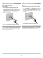
10. CLEANING AND CONSERVATION
Exchanger filled with dirt causes in heat output and air flow
drop.
If cleaning of heat exchanger is needed use listed guidelines.
Disconnect power supply of unit.
Dismount inlet grill guard
It is recommended to use pressured air to clean the
exchanger, air stream need to be directed perpendicular to
exchanger and moved along lamellas.
It is prohibited to use water or sharp items to clean
exchanger.
Other installed equipment do not need be cleaned.
11. OUTLET GRILL ADJUSTING
Outlet lamellas/blades are adjustable within +/- 10 ° range. By
manually setting the angle of the airflow stream, you can adjust
an air barrier to the conditions around the door opening.
22
10. LIMPIEZA Y CONSERVACIÓN
El intercambiador lleno de suciedad causa la salida de calor
interna y la caída del flujo de aire.
Si es necesario limpiar el intercambiador de calor, use las
pautas indicadas.
ႛ Desconecte la fuente de alimentación de la unidad.
ႛ Desmonte la protección de la rejilla de entrada.
Se recomienda utilizar aire a presión para limpiar el
intercambiador, la corriente de aire necesita ser dirigida
perpendicularmente al intercambiador y desplazada a lo
largo de lamas.
ႛ Está prohibido usar agua o artículos afilados para
limpiar el intercambiador.
ႛ
No es necesario limpiar otros equipos instalados.
11. AJUSTE DE LA REJILLA DE SALIDA DE AIRE
Las lamas / láminas de salida son ajustables dentro del rango
de +/- 10 °. Al ajustar manualmente el ángulo de la corriente
de aire, puede ajustar una barrera de aire a las condiciones
alrededor de la apertura de la puerta.

Please contact your dealer in order to get acquitted with the
warranty terms and its limitation.
In the case of any irregularities in the device operation, please
contact the manufacturer’s service department.
The manufacturer bears no responsibility for operating the
device in a manner inconsistent with its purpose, by persons
not authorised for this, and for damage resulting from this!
Made in EU
SALVADOR ESCODA SA
Provenza 392 P2
08025 Barcelona
Spain
e-mail: [email protected]
www.mundoclima.com
Póngase en contacto con su proveedor para conocer
los términos de la garantía y sus limitaciones.
En caso de irregularidades en el funcionamiento de la
unidad, póngase en contacto con el servicio de asistencia al
cliente del fabricante.
¡El fabricante no se responsabiliza de los daños
causados por el mal manejo del equipo ni por usos para
otros propósitos por personas no autorizadas!
Hecho en UE
SALVADOR ESCODA SA
Provenza 392 P2
08025 Barcelona España
e-mail:
info@mundoclima.com
www.mundoclima.com
12. MANTENIMIENTO Y GARANTÍA
23

www.mundoclima.com
C/ PROVENZA 392 P2
08025 BARCELONA
SPAIN
(+34) 93 446 27 80
-
 1
1
-
 2
2
-
 3
3
-
 4
4
-
 5
5
-
 6
6
-
 7
7
-
 8
8
-
 9
9
-
 10
10
-
 11
11
-
 12
12
-
 13
13
-
 14
14
-
 15
15
-
 16
16
-
 17
17
-
 18
18
-
 19
19
-
 20
20
-
 21
21
-
 22
22
-
 23
23
-
 24
24


mundoclima Series MU-EMP “Embedded Air Curtain” Guía de instalación
- Tipo
- Guía de instalación
Artículos relacionados
-
mundoclima Series MU-GC “Superficial Air Curtain Great Air Flow” Guía de instalación
-
-
-
-
-
Otros documentos
-
 CombiSteel 7001.0130 Información del Producto
-
DeLOCK 60269 Ficha de datos
-
Hama 00046612 El manual del propietario
-
-
-
DeLOCK 60254 Ficha de datos
-
-
-
-
