Profi-pumpe INVERTER Pumpensteuerung 0 El manual del propietario
- Tipo
- El manual del propietario

INVERTER-PUMPENSTEUERUNG
0,75kW
-
7,5kW
PARAMETER SETTING-FEHLERCODES
Technical changes, misprints and mistakes reserved! Newest information about our products can be found online
Technische Änderungen, Druckfehler und Irrtümer vorbehalten! Aktuelle Informationen zu unseren Produkten nden Sie auf:
http://www.pro-pumpe.de
OPERATING INSTRUCTIONS
BEDIENUNGSANLEITUNG
Design parameter(*) table (AC inverter series) for
(*)Ab Produktionsdatum 1.8.21 sind Änderungen vorgenommen worden. Die neue Softwareversion wird durch das Flackern
der Code-Anzeige signalisiert
(*)Changes have been made as of production date 1.8.21. The new software version is signalled by the ickering of the code
display
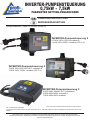
INVERTER-Pumpensteuerung 2
0,75KW 230V/1*230/V-verkabelt &
1,1KW 230V/3*230V, verkabelt (IPC-2-V)
INVERTER-Pumpensteuerung 5
2,2KW 400V IN/400V OUT, verkabelt &
5,5KW 400V/400V, verkabelt &
7,5KW 400V/400V verkabelt
INVERTER-Pumpensteuerung 3
2,2KW 230V IN/3*230V OUT, verkabelt &
1,5KW 230V/1*230V, verkabelt (IPC-3-V)

2
DE
Im Stopmodus (Pumpe läuft nicht) bitte die Tasten „hoch“ und „runter“ gleichzeitig drücken und
1sec lang halten. Das Gerät schaltet automatisch in den „Setting“ Modus um. Mit der Taste
„run“ bestätigen Sie den ausgewählten Wert und speichern ihn. Mit der Taste „Stop“ schalten
Sie die unterschiedlichen Funktions-Ebenen, wobei die angewählten Werte automatisch ge-
speichert werden und das Gerät nach 5 sec in den höheren Level zurück schaltet.
UK
In the stop state, press the <up> and <down> keys at the same time and hold for 1 second
to automatically enter the parameter setting, Press the run key to conrm and save the para-
meters, The stop key is used for the displacement function, and it will automatically save and
return after 5 seconds Upper-level menu.
ES
En el estado de parada, pulse las teclas <arriba> y <abajo> al mismo tiempo y manténgalas
pulsadas durante 1 segundo para entrar automáticamente en el ajuste de parámetros, Pulse
la tecla de marcha para conrmar y guardar los parámetros, La tecla de parada se utiliza para
la función de desplazamiento, y se guardará automáticamente y volverá después de 5 segun-
dos Menú de nivel superior.
IT
Nello stato di arresto, premere contemporaneamente i tasti <su> e <giù> e tenerli premuti per
1 secondo per accedere automaticamente all‘impostazione dei parametri, Premere il tasto di
marcia per confermare e salvare i parametri, Il tasto di arresto viene utilizzato per la funzio-
ne di spostamento e viene salvato automaticamente e ritorna dopo 5 secondi Menu di livello
superiore.
1.
DE
Wenn 5 sec lang das Gerät nicht bedient wird, schaltet das Gerät automatisch in den nächst
höheren Level.
UK
If no operation is performed, the system automatically saves the current parameters and auto-
matically returns to the upper menu after 5 seconds.
ES
Si no se realiza ninguna operación, el sistema guarda automáticamente los parámetros actuales
y vuelve automáticamente al menú superior después de 5 segundos.
IT
Se non viene eseguita alcuna operazione, il sistema salva automaticamente i parametri correnti
e torna automaticamente al menu superiore dopo 5 secondi.
2.

3
DE
Nur die mit „d“ gekennzeichnete Parametergruppe wird benötigt, wenn das Gerät sich im Arbeitsstatus
bendet. (Running-Status= Ruhemodus/Pumpe läuft nicht). Zunächst können die „F“-Parameter
angewählt und geändert werden, danach die „d“-Parameter.
UK
Only the d parameter group is required in working or running state. (The running state is the same as
the stop state, rst enter the F parameter group, and then enter the d parameter group)
ES
Sólo se requiere el grupo de parámetros d en estado de trabajo o de funcionamiento.
(El estado de funcionamiento es el mismo que el estado de parada, primero se introduce el grupo de
parámetros F y luego el grupo de parámetros d).
IT
Solo il gruppo di parametri d è necessario nello stato di lavoro o di funzionamento. (
Lo stato di funzionamento è identico allo stato di arresto; inserire prima il gruppo di
parametri F e poi il gruppo di parametri d).
3.
DE
Tastenbedienung: Kurzes Drücken bewirkt schrittweise langsame Veränderung der Werte.
Längeres Drücken bewirkt eine schnellere Veränderung der Werte.
UK
Key operation: touch to increase or decrease in the smallest unit, Long press to increase or decrease
quickly.
ES
Funcionamiento de las teclas: tocar para aumentar o disminuir en la unidad más pequeña,
pulsar prolongadamente para aumentar o disminuir rápidamente.
IT
Funzionamento dei tasti: toccare per aumentare o diminuire nell‘unità più piccola, premere a
lungo per aumentare o diminuire rapidamente.
4.

4
DE
Nach Anschluss des Drucksensors wird die Konstantdruckregelung automatisch realisiert. (Wenn
F0-14=0, ist die Voreinstellung der Konstantspannungsmodus. Nach der Lauferkennung meldet
kein Sensor einen Fehler und es wird in den Drehzahlregelungsmodus umgeschaltet. Nach An-
schluss des Sensors, Aus- und Wiedereinschalten; wenn F0-14=1, ist er auf den Drehzahlrege-
lungsmodus xiert, AI1 Analogeingang kann als Frequenzquelle angegeben werden (F0-15=1)
UK
After the pressure sensor is connected, the constant pressure control is automatically realized.
(When F0-14=0, the default is constant voltage mode. After running detection, no sensor reports an
error and it will switch to speed control mode. After connecting the sensor, power off and on again;
when F0-14=1, it is xed to speed control mode, AI1 Analog input can be given as frequency source
(F0-15=1)
ES
Después de conectar el sensor de presión, el control de presión constante se realiza automáti-
camente. (Cuando F0-14=0, el valor por defecto es el modo de tensión constante. Después de la
detección de funcionamiento, ningún sensor informa de un error y cambiará al modo de control de
velocidad. Después de conectar el sensor, se apaga y se enciende de nuevo; cuando F0-14=1, se
ja el modo de control de velocidad, la entrada analógica AI1 se puede dar como fuente de frecu-
encia (F0-15=1)
IT
Dopo il collegamento del sensore di pressione, il controllo della pressione costante viene realizzato
automaticamente. (Quando F0-14=0, l‘impostazione predenita è la modalità a tensione costante.
Dopo il rilevamento del funzionamento, nessun sensore segnala un errore e si passa alla modali-
tà di controllo della velocità. Dopo aver collegato il sensore, spegnere e riaccendere il dispositivo;
quando F0-14=1, la modalità di controllo della velocità è ssa, l‘ingresso analogico AI1 può essere
utilizzato come sorgente di frequenza (F0-15=1).
5.
DE
Sensorloser Schutz, Unterspannung, Überspannung, Übertemperatur und Phasenausfallschutz
können durch einmaliges Drücken der Lauftaste aufgehoben werden, der Werkswert kann nach der
Initialisierung wiederhergestellt werden. (Melden Sie einen Fehler direkt, drücken Sie die Stoppta-
ste, um den Fehler zurückzusetzen, keine Löschschutzfunktion)
UK
Sensorless protection, undervoltage, overvoltage, overtemperature, and phase loss protection can
be cancelled by pressing the run key once, The factory value can be restored after initialization.
(Report an error directly, press the stop button to reset the fault, no cancellation protection function)
ES
La protección sin sensor, la subtensión, la sobretensión, la sobretemperatura y la protección por
pérdida de fase pueden cancelarse pulsando una vez la tecla de marcha, El valor de fábrica puede
restablecerse tras la inicialización. (Informar directamente de un error, pulsar el botón de parada
para restablecer el fallo, no hay función de protección de cancelación)
IT
La protezione sensorless, la protezione da sottotensione, sovratensione, sovratemperatura e
perdita di fase possono essere annullate premendo una volta il tasto di marcia, il valore di fabbrica
può essere ripristinato dopo l‘inizializzazione. (Segnalare direttamente un errore, premere il tasto di
arresto per ripristinare il guasto, nessuna funzione di protezione di annullamento).
6.

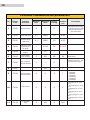
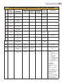
No. Display
code Function
denition Minimum
value Maximum
value Factory
setting Smallest
unit
Annotation
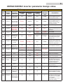
1F0-00 Starting pressu-
re difference 0,1 Set*0.9 0,5 0.1bar Unit: BAR, the maximum
can be adjusted to 90% of
the set pressure value
2F0-01 Water shortage
pressure value F0-21 Set*0.9 0,5 0.1bar
Unit: BAR, the maximum
can be adjusted to 90% of
the set pressure value, 0
means to close the water
shortage protection
3F0-02 Water shortage
running time 1600 30 1S Unit: Second (S)
4F0-03 Allowable shut-
down distur-
bance range
0,0 10,0 0,4 0,1 Note: It is only allowed to
modify this parameter during
shutdown.
5F0-04 Sensor range
selection 1,0 60,0
10,0
16,0
0.1bar
0.1bar
0.75-2.2KW
>2.2KW
6F0-05 Allowable mini-
mum set pressu-
re value
0,1 F0-06 0,5 0.1bar
Unit: BAR (the maximum
value that can be reached
by pressing the key), the
default is 0.5
7F0-06 Allowable maxi-
mum set pressu-
re value F0-05 (F0-04)-1.0 9,0 0.1bar
Unit: BAR (the maximum va-
lue that can be reached by
pressing the up button), the
maximum range value -1
8F0-07
Whether to allow
adjustment of
set pressure
01 1 1 0: Not allowed 1: Allowed
9F0-08 Minimum stop
frequency value
0,00
0,00
F1-04
F1-04
25,00
25,00 0.01HZ The grid frequency is 50HZ
The grid frequency is 60HZ
10 F0-09 PID acceleration
factor 1 99 20 1The larger the value, the
faster the acceleration
11 F0-10 PID deceleration
factor 1 99 20 1The larger the value, the
faster the deceleration
12 F0-11 Whether to allow
downtime 0 2 21
0: Stopping is not allowed
(decelerate and keep run-
ning at the stop frequency);
1: Stop allowed; 2: Zero
frequency operation
13 F0-12 Reset 01011: Restore the factory def-
ault parameters;
14 F0-13 Water pump
anti-sticking
start time
0 72 24 1Unit: hour (reserved)
15 F0-14 Working mode
selection 010
0: Constant voltage mode 1.
Speed regulation mode (re-
quires shutdown to modify)
16 F0-15 Speed control
mode frequency
source selection
0 2 0 1
0: Digital setting 1 (the ▲
and ▼ keys on the operati-
o n p a n e l c a n b e m o d i e d )
1: AI1 analog
(0~20mA/0~10V) 2: Com-
munication setting
5
220VAC/380VAC inverter parameter design value
F0:Water pump control parameter group
Predetermined area

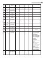
6
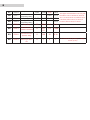
17 F0-16 AI1 input lower limit 0,00 10,00 2,00 0.01V
18 F0-17 AI1 lower limit cor-
responding setting 0,0% 0,1%
19 F0-18 AI1 input upper limit 0,00 10,00 10,00 0.01V
20 F0-19 AI1 upper limit cor-
responding setting 0,1%
21 F0-20 Sleep delay 0.0 100.0 1.0 0.1s
22 F0-21 PID disconnection
protection threshold 0F0-
01
0,3 0.1bar
23 F0-22 PID disconnection
detection delay 0100 10 0.1s
24 F0-23 Sensor type selec-
tion 01010: Current sensor (4-20mA); 1: Voltage
sensor (0-10V)
The upper and lower limits of AI1 vary with
the values of F0-14 and F0-23; when F0-
14=1, F0-16=0, F0-18=10; when F0-14=0,
if F0-23=0, then F0-16=2, F0-18=10, if
F0-23=1, then F0-16=0, F0-18=10.

7
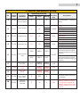
F1:Motor parameter group
No. Display
code
Function
denition
Minimum
value
Maximum
value
Factory
setting
Smallest
unit
Annotation
1F1-00 Set the direction
of motor rotation 01010: Forward rotation; 1: Reverse
rotation;
2F1-01 Carrier frequency 2 20
7,5
4,5
3
2
0.1KHZ
≤3.7KW
5.5KW~30KW
37KW~132KW
>132KW
3F1-02 acceleration time 0,1 60
7,5
15
30
60
0.1s
≤3.7KW
5.5KW~30KW
37KW~132KW
>132KW
4F1-03 deceleration time 0,1 60
7,5
15
30
60
0.1s
≤3.7KW
5.5KW~30KW
37KW~132KW
>132KW
5F1-04 Output frequency
value
20,0
20,0
300,0
300,0
50,0
60,0
0.1HZ
The grid frequency is 50HZ
(the hardware does not support
automatic identication of the grid
frequency)
The grid frequency is 60HZ
(the hardware does not support
automatic identication of the grid
frequency)
6Motor rated cur-
rent value 0,1 Model
setting Model
setting 0,1A
Predetermined area
7F1-06 Motor no-load
current Model
setting Model
setting 0,1A
8F1-07 Motor rated
voltage Model
setting Model
setting 1V
9F1-08 Allow the motor
to run continuo-
usly for time
0 255 0
Unit: hour, 0 means to cancel the
operating time limit, allowing long-
term operation
10 F1-09
Vibration
suppression
coefcient 010 1 0,01
When the motor oscillates, the
oscillation suppression coefci-
ent is adjusted to suppress the
oscillation. When it is set to 0, the
oscillation suppression function is
turned off.

8
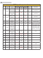
F2:Protection parameters
No. Display
code
Function
denition
Minimum
value
Maximum
value
Factory
setting
Smallest
unit
Annotation
1F2-00
220VAC: Manual
setting of opera-
ting undervolta
380VAC: Manual
setting of opera-
ting undervoltage
value
FF-03
FF-03
280
480
230
410
1V
1V
L means cancel the under-
voltage setting
L means cancel the under-
voltage setting
2F2-01
220VAC: manual
setting of overvol-
tage value
380VAC: manual
setting of overvol-
tage value
350
550
450
900
400
800
1V
1V
H means cancel overvol-
tage setting
L means cancel the under-
voltage setting
3F2-02 Radiator tempe-
rature 60 104 80 1°C H means cancel over
temperature setting
4F2-03 Over temperature
protection setting
(reserved)
60 H 80 1°C If it exceeds 100, it will
display H, H means cancel
over temperature setting
5
F2-04
220/380V three
inputs and three
outputs: input
and output phase
failure protection
options
0 3 3
0: All prohibited 1: Input
prohibited, output allowed
2: Input allowed, output
prohibited 3: Both allowed
6F2-05
Input and output
phase loss pro-
tection delay time
(reserved)
0,0 30,0 1,0 0.1S Reserve
7F2-06 Overload protec-
tion factor 30 % 120 % 100 % 1 %
8F2-07 Antifreeze protec-
tion running time 0 255 0 1min
Predetermined area
9F2-08 Antifreeze pro-
tection operating
frequency 0F1-04 30 1
10 F2-09 Antifreeze protec-
tion action interval
time
0 255 0 1min
11 F2-10 Overwater
pressure alarm
threshold
F2-12 100 % 100 % 0,10 % Relative to the sensor
range
12 F2-11 Over water pres-
sure alarm delay 0 6553,5 1.0 0.1s
13 F2-12 Overwater
pressure reset
threshold
0F2-10 90 % 0,1% Relative to the sensor
range

9
14 F2-13 Protection set-
tings 0x0000 0x1131 0x1101 1
LED units: Motor over-
load protection selection
0 : I n v a l i d
1 : V a l i d
LED tens: 485 communi-
cation timeout processing
0: No protection
1: Protection action and
free stop
2: Alarm but keep the
s t a t u s q u o r u n n i n g
3: Alarm and stop accor-
ding to the set method
LED hundreds: running
under voltage protection
0 : I n v a l i d
1 : Val id
LED thousands: over
voltage protection
0 : I n v a l i d
1: Valid

10
F3:RS485 communication parameters
No. Display
code
Function
denition
Minimum
value
Maximum
value
Factory
setting
Smallest
unit
Annotation
1F3-00 Online function 010
0: On-line function is in-
valid (stand-alone mode);
1: On-line function is valid
(online mode) (need to
stop and modify)
2F3-01 Pump delay time 0,1 100,0 1,0 0.1S
3F3-02 Decrease pump
delay time 0,1 100,0 1,0 0.1S
4F3-03 Reduce the lower
limit frequency of
the pump
1 F1-04 35 0.01HZ
5F3-04 Local address
(online) 1 16 1
6F3-05 Round Robin
Time (online) 0 255 48 1H Unit: 1 hour (invalid for
stand-alone)
7F3-06 Run command
channel selection 010
0: Operation panel running
command channel; 1: 485
communication control
8F3-07 Local address 0 247 1 1
9F3-08 Communication
baud rate setting 0 6 2 1
0: 2400 BPS;
1: 4800 BPS;
2: 9600 BPS;
3: 19200 bps;
4: 38400 bps;
5: 57600 bps;
6: 115200bps
10 F3-09 Data Format 0 5 0 1
0: No parity (N, 8, 1) for
RTU,
1: Even parity (E, 8, 1) for
RTU,
2: Odd parity (0, 8, 1) for
RTU,
3: No parity (N, 8, 2) for
RTU;
4: Even parity (E, 8, 2) for
RTU;
5: Odd parity (0, 8, 2) for
RTU
11 F3-10 Local answer
delay 0 200 5 1ms
Predetermined area

11
12 F3-11 Communication
timeout detection
time
0,1 100 10 0.1s
If the machine does
not receive the correct
data signal within the
time interval dened by
this function code, then
the machine thinks that
the communication has
failed, and the inverter
will determine whether to
protect or maintain the
current operation accor-
ding to the setting of the
communication failure
action mode
13 F3-12 Communication
protocol selection 010 0
0: Compatible with
MD380 protocol 1:
Compatible with Delta M
protocol

12
FF group: manufacturer parameters
No. Display
code
Function
denition
Minimum
value
Maximum
value
Factory
setting
Smallest
unit
Annotation
1FF-00 Factory pass-
word 0 65535 0 1The password is set
successfully, it takes 3
minutes to take effect
2FF-01 Inverter model 0 53 28 1
220V:
0 0.4KW
1 0.75KW 2 1.5KW
3 2.2KW 4 3.0KW
5 4.0KW 6 5.5KW
7 7.5KW 8 11KW
9 15KW 10 18.5KW
11 22KW 12 30KW
13 37KW 14 45KW
15 55KW 16 75KW
17 90KW 18 110KW
19 132KW 20 1 6 0 K W
380V:
21 0.4KW 22 0.75KW
23 1.5KW 24 2.2KW
25 3.0KW 26 4.0KW
27 5.5KW 28 7.5KW
29 11KW 30 15KW
31 18.5KW 32 22KW
33 30KW 34 37KW
35 45KW 36 55KW
37 75KW 38 90KW
39 110KW 40 132KW
41 160KW 42 185KW
43 200KW 44 220KW
45 250KW 46 280KW
47 315KW 48 350KW
49 375KW 50 400KW
51 500KW 52 630KW
53 750KW
Predetermined area
3FF-02 Dead time 2,5 6,5 Model
setting 0.1μS S e t d e a d t i m e
0.4-4.0KW 2.8μS
5.5-750KW 3.2μS
4FF-03 Underpressure
threshold 50 F2-00 Model
setting 1v
Below display P.OFF.
220V model: the default
value is 180V; 380V
model: the default value
is 360V
5FF-04 Voltage correc-
tion factor 0,01 3Model
setting 0,01 Set voltage correction
coefcient
6FF-05 Current correc-
tion factor 0,01 3Model
setting 0,01 Set current correction
coefcient
7FF-06 Temperature
detection method
selection 0101
0: type (sensor con-
nected to power supply)
1: Type (sensor groun-
ding)
8FF-07 Reserve
9FF-08 Reserve
10 FF-09 Special function
selection 0x0000 0x0121 0x0100 0LED units: clear selection
of accumulated running
time
0: invalid
1: Effective LED ten digits:
model selection
0: General purpose model
(G) 1: Light load model (P)
2: Heavy-duty model (Z)
Hundreds of LEDs: reser-
ved Thousands of LEDs:
reserved

13
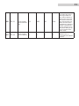
No. Display
code Function
denition
Minimum
value
Maximum
value
Factory
setting
Smallest
unit
Annotation
1d-00 Output frequency 0.01Hz
2d-01 Set frequency 0.01Hz
3d-02 The output vol-
tage 1V
4d-03 Bus voltage (V) 1V
5d-04 Output current 0.1A
6d-05 Motor speed
(RPM/min) 1
Group d: monitoring parameters and fault records
7d-06 Analog input AI1
(V/mA) 0.01V
8d-07 Analog input AI2
(V) 0.01V (Reserve)
9d-08 PID setting value
(Bar) 0.1Bar
Predetermined area
10 d-09 PID feedback
value (Bar) 0.1Bar
11 d-10 Input terminal
status 0x0000 0x003f (Reserve)
12 d-11 Output terminal
status 0x0000 0x000f (Reserve)
13 d-12 Inverter running
status 0x0000 0xFFFF 0:FFFFH
BIT 0: run/stop
BIT 1: forward/reverse
BIT 2: Jog
BIT 3: DC braking
BIT 4: reserved
BIT 5: Overvoltage limit
BIT 6: Constant speed
frequency reduction
BIT 7: Overcurrent limit
BIT 8~9:00-
zero speed/01-
acceleration/10-
deceleration/11-uniform
speed
BIT 10: Overload pre-
alarm
BIT 11: reserved
BIT 12~13 run command
channel: 00-panel/01-
communication/10-
reserved
BIT 14~15 bus voltage
status: 00-normal/01-low
voltage protection/10-
overvoltage protection

14 d-13 Module tempera-
ture °C
15 d-14 Software upgrade
date (year)
16 d-15 Software upgrade
date (month, day)
17 d-16 Type of third
failure
18 d-17 Type of second
failure
19 d-18 Type of last
failure
20 d-19 Operating fre-
quency at current
fault
21 d-20 Output current at
current fault
22 d-21 Bus voltage at
current fault
23 d-22 Input terminal
status at current
fault
(Reserve)
24 d-23 Output terminal
status at current
fault
(Reserve)
25 d-24 Inverter status at
current fault
0+FFFFH BIT0: run/stop
BIT1: forward/reverse
BIT2: Jog
BIT3: DC braking
BIT4: reserved
BIT5: Overvoltage limit
BIT6: Constant speed
frequency reduction
BIT7: Overcurrent limit
BIT8~9:00-
zero speed/01-
acceleration/10-
deceleration/11-uniform
speed
BIT10: Overload pre-
alarm
BIT11: reserved
BIT12~13 run command
channel: 00-panel/01-
communication/10-
reserved
BIT14~15 bus voltage
status: 00-normal/01-low
voltage protection/10-
overvoltage protection
26 d-25 The temperature
at the time of the
current fault
14

15
27 d-26 Cumulative run-
ning time of the
machine (hours)
28 d-27 Accumulated
power-on time
of the machine
(hours)
29 d-28 Fan cumulative
running time
(hours)

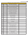
16
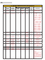
NO. Error code Code function description Faults and solutions
1E0C1 Overcurrent during accelerated operation
2E0C2 Overcurrent during deceleration operation
3E0C3 Overcurrent in uniform operation
4EHU1 Overvoltage during accelerated operation
5EHU2 Overvoltage during deceleration
6EHU3 Overpressure in uniform operation
7EHU4 Overvoltage during shutdown
8ELU0 Undervoltage during operation
Display code and description
9ESC1 Power module failure
10 E-OH Radiator overheated
11 EOL1 Inverter overload
12 EOL2 Inverter overload
13 ECPU CPU failure
14 EPID PID feedback disconnection (sensor failure)
15 E485 RS485 communication failure
16 ECCF Current detection failure
17 EEEP EEPROM read and write error
18 EPLI Phase loss on the input side
19 EPLO Phase loss on the output side
20 E-LP Water shortage
21 A-16 485 communication timeout alarm

22 A-17 No host
23 A-18 No chance
24 A-19 Duplicate address
25 A-20 Water pressure warning
26 E-EF External device failure
27 (Reserve)
ETUN Burst pipe
28 E-LT Running time arrived
17
Imprint/Impressum
Amur S.à r.l.
www.amur.lu
Email: info@amur.lu
Tel.: (+49) 0611-9 45 87 77-0
Fax: (+49) 0611-9 45 87 77-11
-
 1
1
-
 2
2
-
 3
3
-
 4
4
-
 5
5
-
 6
6
-
 7
7
-
 8
8
-
 9
9
-
 10
10
-
 11
11
-
 12
12
-
 13
13
-
 14
14
-
 15
15
-
 16
16
-
 17
17


Profi-pumpe INVERTER Pumpensteuerung 0 El manual del propietario
- Tipo
- El manual del propietario
en otros idiomas
Otros documentos
-
WEG CFW100 series Guía de inicio rápido
-
WEG CFW300 Guía de inicio rápido
-
-
-
-
-
-
WEG CFW701 Guía de inicio rápido
-
-