ATEN VS-132 Manual de usuario
- Categoría
- Divisores de video
- Tipo
- Manual de usuario
Este manual también es adecuado para

2-Port Video Splitter
VS-132
User Guide
© Copyright 2010 ATEN
®
International Co., Ltd.
ATEN and the ATEN logo are trademarks of ATEN International Co., Ltd. All rights reserved. All other
trademarks are the property of their respective owners.
This product is RoHS compliant.
Part No. PAPE-1285-140G Printing Date: 03/2010
VS-132 2-Port Video Splitter User Guide
Répartiteur vidéo à 2 ports VS-132 – Guide d’utilisation
VS-132 2-Port-Grafi ksplitter Benutzerhandbuch
VS-132 Repartidor gráfi co de 2 puertos Manual del usuario
Requirements
Source Device
The following equipment must be installed on the source device or computer that
acts as a source of VGA content:
• HDB-15 connector
Display Device(s)
• A VGA, SVGA, XGA, UXGA, or multisync display device or receiver with an
HDB-15 connector
Notes: The VS-132 is not suitable for CGA, EGA, or Monochrome monitors that
use a digital signal.
Cables
• Use VGA cable to connect the source device to the VS-132
Note: The VGA cable does not come with the package and must be purchased
separately.
Confi guration minimale
Périphérique(s) source(s)
Les composants suivants doivent être installés sur le périphérique source ou sur
l'ordinateur agissant en tant que périphérique source du contenu VGA :
• Connecteur HDB-15
Périphérique d’affichage
• Un périphérique d’affi chage VGA, SVGA, XGA, UXGA ou multisync ou un récepteur
équipé d'un connecteur HDB-15
Remarque: Le VS-132 ne convient pas aux moniteurs de type CGA, EGA ou
monochrome qui utilisent un signal numérique.
Câbles
• Utilisez un câble VGA pour raccorder le périphérique source au VS-132
Remarque: Le câble VGA n’est pas fourni et doit être acheté à part.
Description de l’appareil
A
Vue avant
1. Voyant de signal
2. Voyant d’alimentation
3. Ports de sortie vidéo
4. Port d’entrée vidéo
5. Commutateur de gain
6. Prise d’alimentation CC
Voraussetzungen
Signalquelle(n)
Auf den Signalquellen oder Computern, die das VGA-Signal senden, muss
mindestens Folgendes installiert sein:
• HDB-15-Anschluss
Anzeigegerät
• Ein VGA-, SVGA-, XGA-, UXGA- oder Multisync-Anzeigegerät bzw.
–Empfangsgerät mit HDB-15-Buchse
Hinweis: Der VS-132 eignet sich nicht für CGA-, EGA- oder Monochrom-
Monitore, die digitale Videosignale verwenden.
Kabel
• Verbinden Sie den VS-132 mit der Signalquelle über ein VGA-Kabel.
Hinweis: Das VGA-Kabel gehört nicht zum Lieferumfang. Sie müssen es
separat erwerben.
Requisitos
Dispositivo(s) fuente
En los dispositivos fuente de señal VGA u ordenadores que se conectan al
equipo debe estar instalado lo siguiente:
• Conector HDB-15
Dispositivo de visualización
• Un dispositivo de visualización o receptor VGA, SVGA, XGA, UXGA o multisync
con una toma HDB-15
Nota: El VS-132 no es compatible con monitores CGA, EGA o monocromáticos
que empleen señales gráfi cas digitales.
Cables
• Emplee un cable VGA para conectar el dispositivo gráfi co fuente al VS-132.
Nota: El cable VGA no se incluye en el paquete y debe ser adquirido por
separado.
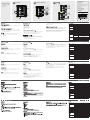
Hardware Review
A
Front View
1. Signal LED
2. Power LED
3. Video Out Ports
4. Video In Port
5. Gain Switch
6. DC Jack
Hardware Installation
B
• Before beginning the installation procedure, ensure that all equipment to be
connected is powered off.
• To prevent damage to your installation, make sure that all devices are properly
grounded.
Standalone Installation
1. Plug the female end of a male-to-female VGA cable into the VS-132's Video
In port; plug the male end of the cable into the computer's video output port.
2. Plug the monitor cables into any available Video Out port.
3. Plug the power adapter (supplied with this package) into a DC source; plug
the adapter's power cable into the VS-132’s DC Power Jack.
4. Power on all equipment.
Installation du matériel
B
• Avant de démarrer la procédure d'installation, assurez-vous que tous les
périphériques à connecter sont éteints.
• Afin d'éviter d'endommager votre installation, vérifiez que tous les périphériques
sont correctement reliés à la terre.
Installation autonome
1. Branchez l’extrémité femelle d’un câble VGA mâle-femelle dans le port d’entrée
vidéo du VS-132 et branchez l’extrémité mâle du câble dans le port de sortie
vidéo de l’ordinateur.
2. Branchez les câbles du moniteur dans n’importe quel port de sortie vidéo
disponible.
3. Branchez l'adaptateur secteur (fourni) dans une prise de courant CC et
raccordez le câble d’alimentation de l’adaptateur à la prise d'alimentation CC
du VS-132.
4. Allumez tous les appareils.
Hardwareübersicht
A
Vorderseite des
1. Signal-LED
2. LED-Betriebsanzeige
3. Grafi kausgänge
4. Grafi keingang
5. Signalpegelumschalter
6. Stromeingangsbuchse
Hardware installieren
B
• Schalten Sie vor der Installation alle anzuschließenden Geräte aus.
• Um eine Beschädigung Ihrer Geräte zu vermeiden, müssen alle Geräte
ordnungsgemäß geerdet sein.
Einzelinstallation
1. Verbinden Sie den ersten Stecker (Weiblein) des VGA-Kabels mit dem
Grafikeingang des VS-132, und verbinden Sie das andere Ende (Männlein)
mit dem Grafikkartenausgang Ihres Computers.
2. Schließen Sie die Monitorkabel an je einen freien Grafikausgang an.
3. Verbinden Sie das mitgelieferte Netzteil mit einer Steckdose und sein
Netzkabel mit der Stromeingangsbuchse des VS-132.
4. Schalten Sie alle Geräte ein.
Presentación del hardware
A
Vista frontal
1. Indicador de señal
2. Indicador LED de alimentación
3. Puertos de salida de señal gráfi ca
4. Puerto de entrada de señal gráfi ca
5. Conmutador de ganancia
6. Entrada de alimentación
Instalar el hardware
B
• Antes de iniciar el proceso de instalación, asegúrese de que todos los equipos
que vaya a conectar estén apagados.
• Para evitar daños en los dispositivos, verifique que todos ellos estén
conectados a tierra correctamente.
Instalación individual
1. Inserte extremo hembra del cable VGA en el puerto de entrada gráfica del
VS-132 y el extremo macho del cable en el puerto de la tarjeta gráfica del
ordenador.
2. Conecte cada uno de los cables de los monitores en un puerto de salida
gráfica libre.
3. Conecte el adaptador de alimentación incluido a una toma eléctrica y el otro
extremo a la entrada de alimentación del VS-132.
4. Encienda todos los equipos.
www.aten.com
www.aten.com
www.aten.com
www.aten.com
Cascading
C
To provide video display for more monitors, additional VS-132s can be cascaded.
Use a high density HDB-15 male/female video extender cable to connect any
available Video Out port on the higher level VS-132 to the Video In port of the lower
level VS-132.
You can cascade as many VS-132s as there are ports available. Theoretically,
there is no limit to the number of splitters that can be cascaded, but the quality will
deteriorate as you get further away from the video signal.
Installation en cascade
C
Pour affi cher vos données sur d'autres moniteurs, vous pouvez installer et brancher
en cascade d'autres répartiteurs VS-132. Utilisez un câble d'extension vidéo mâle/
femelle HDB-15 de haute densité pour relier un port de sortie vidéo (Video Out)
disponible du VS-132 de niveau supérieur au port d'entrée vidéo (Video In) du VS-
132 de niveau inférieur.
Vous pouvez installer en cascade autant de répartiteurs vidéo VS-132 qu’il y a de
ports disponibles. En théorie, vous pouvez installer un nombre illimité de répartiteurs
en cascade, mais notez que plus l'installation en cascade est complexe, plus la
qualité du signal vidéo s'en trouvera altérée.
Reihenschaltung
C
Um eine Bildausgabe auf weiteren Monitoren zu erhalten, können Sie weitere VS-
132-Geräte in Reihe schalten. Verwenden Sie ein High-Density HDB-15-VGA-
Verlängerungskabel (Männlein/Weiblein), um einen beliebigen Ausgang Video
Out des höhergeordneten VS-132 mit dem Signaleingang Video In des VS-132
niedrigerer Ordnung zu verbinden.
Sie können so viele VS-132 hintereinander schalten, wie Ports zur Verfügung
stehen. Theoretisch ist die Anzahl der zu kaskadierenden Splitter unbegrenzt,
allerdings verringert sich in der Praxis die Bildqualität, je länger der Weg ist, den das
Grafi ksignal zurücklegen muss.
Instalación en cascada
C
Para ofrecer una visualización de la señal gráfi ca en más monitores, puede conectar
varios VS-132 en cascada. Emplee un cable alargador gráfi co macho/hembra HDB-
15 de alta densidad para conectar cualquier puerto de salida Video Out del VS-132
de nivel superior a la entrada Video In del VS-132 de nivel inferior.
Es posible conectar en cascada tantos VS-132 como haya puertos libres.
Teóricamente, el número de repartidores que se puede conectar en cascada no
viene limitado. No obstante, la calidad de imagen se deteriora con la distancia que la
señal gráfi ca tiene que recorrer.
Specifi cations
Function VS-132
Display Connections 2
Connectors
Video In 1 x HDB-15 Male (Blue)
Video Out 2 x HDB-15 Female (Blue)
Power 1 x DC Jack
LEDs
Signal 1 (Green)
Power 1 (Orange)
Switch Gain 1 x Slide Switch
Video 1920 x 1440 @ 60Hz
Bandwidth 350 MHz
Cable Distance Up to 65 m
Power Consumption DC 5.3 V, 0.48 W
Environment
Operating Temp. 0–50°C
Storage Temp. -20–60°C
Humidity 0–80% RH, Non-condensing
Physical Properties
Housing Metal
Weight 0.19 kg
Dimensions
(L x W x H)
10.40 x 9.80 x 2.40 cm
Caractéristiques techniques
Fonction VS-132
Connexions pour l’affi chage 2
Connecteurs
Entrée vidéo 1 connecteur HDB-15 mâle (bleu)
Sortie vidéo 2 connecteurs HDB-15 femelles (bleus)
Alimentation 1 prise d’alimentation CC
Voyants
Signal 1 voyant (vert)
Alimentation 1 voyant (orange)
Commutateur Gain 1 interrupteur coulissant
Vidéo 1920 x 1440 à 60 Hz
Bande passante 350 MHz
Longueur de câble 65 m maxi
Consommation électrique CC 5,3 V, 0,48 W
Environnement
Température de
fonctionnement
0 à 50 °C
Température de
stockage
-20 à 60 °C
Humidité
Humidité relative de 0 à 80 %, sans
condensation
Propriétés
physiques
Boîtier Métallique
Poids 0,19 kg
Dimensions
(Long. x Larg. x Haut.)
10,40 x 9,80 x 2,40 cm
Technische Daten
Funktion VS-132
Monitoranschlüsse 2
Anschlüsse
Grafi keingänge 1 x HDB-15 Männlein (blau)
Grafi kausgänge 2 x HDB-15 Weiblein (blau)
Stromversorgung 1 x Stromeingangsbuchse
LED-Anzeigen
Signal 1 (grün)
Stromversorgung 1 (orange)
Schalter
Signalpegel
(Gewinn)
1 x Schiebeschalter
Bildschirm 1920 x 1440 bei 60Hz
Bandbreite 350 MHz
Kabellänge Bis zu 65 m
Stromverbrauch 5,3 V=, 0,48 W
Umgebung
Betriebstemperatur 0-50 °C
Lagertemperatur -20-60 °C
Feuchtigkeit
0 -80% rel. Luftfeuchte, nicht
kondensierend
Physische
Eigenschaften
Gehäuse Metall
Gewicht 0,19 kg
Abmessungen
(L x B x H)
10,40 x 9,80 x 2,40 cm
Especifi caciones
Función VS-132
Puertos de conexión para pantalla 2
Conectores
Entrada de vídeo 1 conector HDB-15 macho (azul)
Salida de vídeo 2 conectores HDB-15 hembra (azules)
Alimentación 1 toma de c.c.
Indicadores LED
Señal 1 (verde)
Alimentación 1 (naranja)
Conmutador Ganancia 1 interruptor deslizable
Señal gráfi ca 1920 x 1440 a 60Hz
Ancho de banda 350 MHz
Longitud de cable Hasta 65 m
Consumo 5,3 V de c.c., 0,48 W
Entorno
Temperatura de
funcionamiento
0 a 50 °C
Temperatura de
almacenamiento
-20 a 60 °C
Humedad 0 a 80% de HR, sin condensar
Propiedades físicas
Carcasa Metálica
Peso 0,19 kg
Dimensiones
(L x An x Al)
10,40 x 9,80 x 2,40 cm
The following contains information that relates to China:
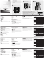
Package Contents
1 VS-132 2-Port Video Splitter
1 Power Adapter
1 User Guide
Front View
A
Hardware Installation
Cascading
B C
FCC Information
This equipment has been tested and found to comply with the limits for a Class B digital
device, pursuant to Part 15 of the FCC Rules. These limits are designed to provide reasonable
protection against harmful interference in a residential installation. This equipment generates,
uses and can radiate radio frequency energy, and if not installed and used in accordance with
the instruction manual, may cause interference to radio communications. However, there is no
guarantee that interference will not occur in a particular installation. If this equipment does cause
harmful interference to radio or television reception, which can be determined by turning the
equipment off and on, the user is encouraged to try to correct the interference by one or more of
the following measures:
• Reorient or relocate the receiving antenna;
• Increase the separation between the equipment and receiver;
• Connect the equipment into an outlet on a circuit different from that which the receiver is
connected;
• Consult the dealer/an experienced radio/television technician for help.
Online Registration
International:
http://support.aten.com
North America:
http://www.aten-usa.com/product_
registration
Technical Phone Support
International:
886-2-86926959
North America:
1-888-999-ATEN (ATEN TECH)
1-732-356-1703 (ATEN NJ)
United Kingdom:
44-8-4481-58923
1
1
2
3
3
2
4
5
6
La página se está cargando ...
Transcripción de documentos
Package Contents B 1 VS-132 2-Port Video Splitter C Hardware Installation Cascading 1 Power Adapter 1 User Guide A 2 Front View 1 3 2-Port Video Splitter VS-132 3 1 User Guide 2 4 5 © Copyright 2010 ATEN® International Co., Ltd. ATEN and the ATEN logo are trademarks of ATEN International Co., Ltd. All rights reserved. All other trademarks are the property of their respective owners. 6 This product is RoHS compliant. Part No. PAPE-1285-140G Printing Date: 03/2010 FCC Information This equipment has been tested and found to comply with the limits for a Class B digital device, pursuant to Part 15 of the FCC Rules. These limits are designed to provide reasonable protection against harmful interference in a residential installation. This equipment generates, uses and can radiate radio frequency energy, and if not installed and used in accordance with the instruction manual, may cause interference to radio communications. However, there is no guarantee that interference will not occur in a particular installation. If this equipment does cause harmful interference to radio or television reception, which can be determined by turning the equipment off and on, the user is encouraged to try to correct the interference by one or more of the following measures: • Reorient or relocate the receiving antenna; • Increase the separation between the equipment and receiver; • Connect the equipment into an outlet on a circuit different from that which the receiver is connected; • Consult the dealer/an experienced radio/television technician for help. Online Registration The following contains information that relates to China: International: http://support.aten.com North America: http://www.aten-usa.com/product_ registration Technical Phone Support International: 886-2-86926959 North America: United Kingdom: 44-8-4481-58923 1-888-999-ATEN (ATEN TECH) 1-732-356-1703 (ATEN NJ) VS-132 2-Port Video Splitter User Guide www.aten.com Requirements Hardware Review Source Device Front View The following equipment must be installed on the source device or computer that acts as a source of VGA content: • HDB-15 connector 1. Signal LED 2. Power LED 3. Video Out Ports 4. Video In Port 5. Gain Switch 6. DC Jack Display Device(s) • A VGA, SVGA, XGA, UXGA, or multisync display device or receiver with an HDB-15 connector Notes: The VS-132 is not suitable for CGA, EGA, or Monochrome monitors that use a digital signal. Cables • Use VGA cable to connect the source device to the VS-132 Note: The VGA cable does not come with the package and must be purchased separately. Cascading C A To provide video display for more monitors, additional VS-132s can be cascaded. Use a high density HDB-15 male/female video extender cable to connect any available Video Out port on the higher level VS-132 to the Video In port of the lower level VS-132. You can cascade as many VS-132s as there are ports available. Theoretically, there is no limit to the number of splitters that can be cascaded, but the quality will deteriorate as you get further away from the video signal. Hardware Installation Specifications Function 2 Video In Connectors Video Out Power LEDs Switch B 1 x HDB-15 Male (Blue) 2 x HDB-15 Female (Blue) 1 x DC Jack Signal 1 (Green) Power 1 (Orange) Gain Video • Before beginning the installation procedure, ensure that all equipment to be connected is powered off. • To prevent damage to your installation, make sure that all devices are properly grounded. VS-132 Display Connections 1 x Slide Switch 1920 x 1440 @ 60Hz Bandwidth 350 MHz Cable Distance Up to 65 m Power Consumption DC 5.3 V, 0.48 W Operating Temp. Standalone Installation Environment 1. Plug the female end of a male-to-female VGA cable into the VS-132's Video In port; plug the male end of the cable into the computer's video output port. 2. Plug the monitor cables into any available Video Out port. 3. Plug the power adapter (supplied with this package) into a DC source; plug the adapter's power cable into the VS-132’s DC Power Jack. 4. Power on all equipment. Storage Temp. Humidity Physical Properties 0–50°C -20–60°C 0–80% RH, Non-condensing Housing Metal Weight 0.19 kg Dimensions (L x W x H) 10.40 x 9.80 x 2.40 cm www.aten.com Répartiteur vidéo à 2 ports VS-132 – Guide d’utilisation Configuration minimale Installation du matériel Périphérique(s) source(s) • Avant de démarrer la procédure d'installation, assurez-vous que tous les périphériques à connecter sont éteints. • Afin d'éviter d'endommager votre installation, vérifiez que tous les périphériques sont correctement reliés à la terre. Pour afficher vos données sur d'autres moniteurs, vous pouvez installer et brancher en cascade d'autres répartiteurs VS-132. Utilisez un câble d'extension vidéo mâle/ femelle HDB-15 de haute densité pour relier un port de sortie vidéo (Video Out) disponible du VS-132 de niveau supérieur au port d'entrée vidéo (Video In) du VS132 de niveau inférieur. Périphérique d’affichage Installation autonome • Un périphérique d’affichage VGA, SVGA, XGA, UXGA ou multisync ou un récepteur équipé d'un connecteur HDB-15 Remarque: Le VS-132 ne convient pas aux moniteurs de type CGA, EGA ou monochrome qui utilisent un signal numérique. 1. Branchez l’extrémité femelle d’un câble VGA mâle-femelle dans le port d’entrée vidéo du VS-132 et branchez l’extrémité mâle du câble dans le port de sortie vidéo de l’ordinateur. 2. Branchez les câbles du moniteur dans n’importe quel port de sortie vidéo disponible. 3. Branchez l'adaptateur secteur (fourni) dans une prise de courant CC et raccordez le câble d’alimentation de l’adaptateur à la prise d'alimentation CC du VS-132. 4. Allumez tous les appareils. Vous pouvez installer en cascade autant de répartiteurs vidéo VS-132 qu’il y a de ports disponibles. En théorie, vous pouvez installer un nombre illimité de répartiteurs en cascade, mais notez que plus l'installation en cascade est complexe, plus la qualité du signal vidéo s'en trouvera altérée. Les composants suivants doivent être installés sur le périphérique source ou sur l'ordinateur agissant en tant que périphérique source du contenu VGA : • Connecteur HDB-15 Câbles • Utilisez un câble VGA pour raccorder le périphérique source au VS-132 Remarque: Le câble VGA n’est pas fourni et doit être acheté à part. Description de l’appareil Installation en cascade C B Caractéristiques techniques Fonction Connexions pour l’affichage Connecteurs Entrée vidéo 1 connecteur HDB-15 mâle (bleu) Sortie vidéo 2 connecteurs HDB-15 femelles (bleus) Alimentation 1 prise d’alimentation CC Signal Voyants Alimentation Commutateur Gain 1920 x 1440 à 60 Hz Bande passante 350 MHz Longueur de câble 65 m maxi Consommation électrique Température de fonctionnement Température de Environnement stockage Humidité A Propriétés physiques 1. Voyant de signal 2. Voyant d’alimentation 3. Ports de sortie vidéo 4. Port d’entrée vidéo 5. Commutateur de gain 6. Prise d’alimentation CC 1 voyant (vert) 1 voyant (orange) 1 interrupteur coulissant Vidéo Vue avant VS-132 2 CC 5,3 V, 0,48 W 0 à 50 °C -20 à 60 °C Humidité relative de 0 à 80 %, sans condensation Boîtier Métallique Poids 0,19 kg Dimensions (Long. x Larg. x Haut.) 10,40 x 9,80 x 2,40 cm www.aten.com VS-132 2-Port-Grafiksplitter Benutzerhandbuch Voraussetzungen Hardwareübersicht Signalquelle(n) Vorderseite des Auf den Signalquellen oder Computern, die das VGA-Signal senden, muss mindestens Folgendes installiert sein: • HDB-15-Anschluss 1. Signal-LED 2. LED-Betriebsanzeige 3. Grafikausgänge 4. Grafikeingang 5. Signalpegelumschalter 6. Stromeingangsbuchse Anzeigegerät • Ein VGA-, SVGA-, XGA-, UXGA- oder Multisync-Anzeigegerät bzw. –Empfangsgerät mit HDB-15-Buchse Hinweis: Der VS-132 eignet sich nicht für CGA-, EGA- oder MonochromMonitore, die digitale Videosignale verwenden. Kabel • Verbinden Sie den VS-132 mit der Signalquelle über ein VGA-Kabel. Hinweis: Das VGA-Kabel gehört nicht zum Lieferumfang. Sie müssen es separat erwerben. Reihenschaltung C A Um eine Bildausgabe auf weiteren Monitoren zu erhalten, können Sie weitere VS132-Geräte in Reihe schalten. Verwenden Sie ein High-Density HDB-15-VGAVerlängerungskabel (Männlein/Weiblein), um einen beliebigen Ausgang Video Out des höhergeordneten VS-132 mit dem Signaleingang Video In des VS-132 niedrigerer Ordnung zu verbinden. Hardware installieren Sie können so viele VS-132 hintereinander schalten, wie Ports zur Verfügung stehen. Theoretisch ist die Anzahl der zu kaskadierenden Splitter unbegrenzt, allerdings verringert sich in der Praxis die Bildqualität, je länger der Weg ist, den das Grafiksignal zurücklegen muss. B • Schalten Sie vor der Installation alle anzuschließenden Geräte aus. • Um eine Beschädigung Ihrer Geräte zu vermeiden, müssen alle Geräte ordnungsgemäß geerdet sein. Technische Daten Funktion Monitoranschlüsse Anschlüsse 2 Grafikeingänge 1 x HDB-15 Männlein (blau) Grafikausgänge 2 x HDB-15 Weiblein (blau) Stromversorgung 1 x Stromeingangsbuchse Signal LED-Anzeigen Stromversorgung Signalpegel (Gewinn) Schalter Bildschirm Einzelinstallation 1 (grün) 1 (orange) 1 x Schiebeschalter 1920 x 1440 bei 60Hz Bandbreite 350 MHz Kabellänge Bis zu 65 m Stromverbrauch 5,3 V=, 0,48 W Betriebstemperatur 1. Verbinden Sie den ersten Stecker (Weiblein) des VGA-Kabels mit dem Grafikeingang des VS-132, und verbinden Sie das andere Ende (Männlein) mit dem Grafikkartenausgang Ihres Computers. 2. Schließen Sie die Monitorkabel an je einen freien Grafikausgang an. 3. Verbinden Sie das mitgelieferte Netzteil mit einer Steckdose und sein Netzkabel mit der Stromeingangsbuchse des VS-132. 4. Schalten Sie alle Geräte ein. VS-132 Lagertemperatur Umgebung Feuchtigkeit Physische Eigenschaften 0-50 °C -20-60 °C 0 -80% rel. Luftfeuchte, nicht kondensierend Gehäuse Metall Gewicht 0,19 kg Abmessungen (L x B x H) 10,40 x 9,80 x 2,40 cm www.aten.com VS-132 Repartidor gráfico de 2 puertos Manual del usuario Requisitos Presentación del hardware Dispositivo(s) fuente Vista frontal En los dispositivos fuente de señal VGA u ordenadores que se conectan al equipo debe estar instalado lo siguiente: • Conector HDB-15 1. Indicador de señal 2. Indicador LED de alimentación 3. Puertos de salida de señal gráfica 4. Puerto de entrada de señal gráfica 5. Conmutador de ganancia 6. Entrada de alimentación Dispositivo de visualización • Un dispositivo de visualización o receptor VGA, SVGA, XGA, UXGA o multisync con una toma HDB-15 Nota: El VS-132 no es compatible con monitores CGA, EGA o monocromáticos que empleen señales gráficas digitales. Cables • Emplee un cable VGA para conectar el dispositivo gráfico fuente al VS-132. Nota: El cable VGA no se incluye en el paquete y debe ser adquirido por separado. Instalar el hardware A Instalación en cascada C Para ofrecer una visualización de la señal gráfica en más monitores, puede conectar varios VS-132 en cascada. Emplee un cable alargador gráfico macho/hembra HDB15 de alta densidad para conectar cualquier puerto de salida Video Out del VS-132 de nivel superior a la entrada Video In del VS-132 de nivel inferior. B • Antes de iniciar el proceso de instalación, asegúrese de que todos los equipos que vaya a conectar estén apagados. • Para evitar daños en los dispositivos, verifique que todos ellos estén conectados a tierra correctamente. Es posible conectar en cascada tantos VS-132 como haya puertos libres. Teóricamente, el número de repartidores que se puede conectar en cascada no viene limitado. No obstante, la calidad de imagen se deteriora con la distancia que la señal gráfica tiene que recorrer. Especificaciones Función Puertos de conexión para pantalla Entrada de vídeo Conectores Alimentación Indicadores LED Conmutador Señal Alimentación Ganancia Señal gráfica 1 toma de c.c. 1 (verde) 1 (naranja) 1 interruptor deslizable Hasta 65 m Consumo 5,3 V de c.c., 0,48 W Temperatura de funcionamiento Temperatura de almacenamiento Humedad Carcasa Propiedades físicas 2 conectores HDB-15 hembra (azules) 350 MHz Longitud de cable Entorno 2 1 conector HDB-15 macho (azul) 1920 x 1440 a 60Hz Ancho de banda Instalación individual 1. Inserte extremo hembra del cable VGA en el puerto de entrada gráfica del VS-132 y el extremo macho del cable en el puerto de la tarjeta gráfica del ordenador. 2. Conecte cada uno de los cables de los monitores en un puerto de salida gráfica libre. 3. Conecte el adaptador de alimentación incluido a una toma eléctrica y el otro extremo a la entrada de alimentación del VS-132. 4. Encienda todos los equipos. Salida de vídeo VS-132 Peso Dimensiones (L x An x Al) 0 a 50 °C -20 a 60 °C 0 a 80% de HR, sin condensar Metálica 0,19 kg 10,40 x 9,80 x 2,40 cm-
 1
1
-
 2
2


ATEN VS-132 Manual de usuario
- Categoría
- Divisores de video
- Tipo
- Manual de usuario
- Este manual también es adecuado para
En otros idiomas
- français: ATEN VS-132 Manuel utilisateur
- italiano: ATEN VS-132 Manuale utente
- English: ATEN VS-132 User manual
- Deutsch: ATEN VS-132 Benutzerhandbuch
- 日本語: ATEN VS-132 ユーザーマニュアル
Documentos relacionados
-
ATEN VS138A Guía de inicio rápido
-
ATEN VS0204 Guía de inicio rápido
-
ATEN VS0116 Guía de inicio rápido
-
-
ATEN VS98A 2/4/8-Port Video Splitter Guía de inicio rápido
-
-
-
ATEN CE100 Manual de usuario
-
-