ATEN CE100 Manual de usuario
- Categoría
- Conmutadores KVM
- Tipo
- Manual de usuario
ATEN CE100 es un extensor KVM USB mini que permite controlar una computadora desde una ubicación remota, a hasta 100 metros de distancia, usando solo un cable Cat5e. Es compatible con resoluciones de video de hasta 1920 x 1200 a 60 Hz a 30 metros, y 1280 x 1024 a 60 Hz a 100 metros. Incluye un sintonizador de compensación de video para ajustar la calidad de la imagen en la ubicación remota. Además, soporta teclado, ratón y monitor USB, y no requiere alimentación externa para la unidad local, ya que recibe alimentación a través de la conexión USB/VGA.
ATEN CE100 es un extensor KVM USB mini que permite controlar una computadora desde una ubicación remota, a hasta 100 metros de distancia, usando solo un cable Cat5e. Es compatible con resoluciones de video de hasta 1920 x 1200 a 60 Hz a 30 metros, y 1280 x 1024 a 60 Hz a 100 metros. Incluye un sintonizador de compensación de video para ajustar la calidad de la imagen en la ubicación remota. Además, soporta teclado, ratón y monitor USB, y no requiere alimentación externa para la unidad local, ya que recibe alimentación a través de la conexión USB/VGA.

Transcripción de documentos
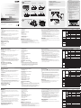
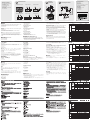
A FCC Information Package Contents Hardware Review CE100R/CE100L Top View CE100L Front View 1 3 CE100R Front View 3 1 2 4 This equipment has been tested and found to comply with the limits for a Class A digital device, pursuant to Part 15 of the FCC Rules. These limits are designed to provide reasonable protection against harmful interference in a residential installation. This equipment generates, uses and can radiate radio frequency energy, and if not installed and used in accordance with the instruction manual, may cause interference to radio communications. However, there is no guarantee that interference will not occur in a particular installation. If this equipment does cause harmful interference to radio or television reception, which can be determined by turning the equipment off and on, the user is encouraged to try to correct the interference by one or more of the following measures: • Reorient or relocate the receiving antenna; • Increase the separation between the equipment and receiver; • Connect the equipment into an outlet on a circuit different from that which the receiver is connected; • Consult the dealer/an experienced radio/television technician for help. 1 CE100L Mini USB KVM Extender (Local Unit) 1 CE100R Mini USB KVM Extender (Remote Unit) 1 USB/VGA Cable 1 Power Adapter (for Remote Unit) 1 Mounting Kit 1 User Instructions 2 4 35 2 2 C 1 1 CE100L/CE100R Rear View 1 6 CE100L Side View 2 7 CE100L CE100R Side View 1 7 81 Connecting the Cables Online Registration 2 9 International: http://support.aten.com North America: http://www.aten-usa.com/product_registration 1 Mini USB KVM Extender Technical Phone Support 3 CE100 International: 886-2-86926959 North America: 1-888-999-ATEN Ext: 4988 United Kingdom: 44-8-4481-58923 Cat 5e Cable (up to 100 m) User Guide CE100R B Hardware Installation Philips Head M3 L:5 The following contains information that relates to China: 2 4 Mounting 1 © Copyright 2012 ATEN® International Co., Ltd. ATEN and the ATEN logo are trademarks of ATEN International Co., Ltd. All rights reserved. All other trademarks are the property of their respective owners. 2 This product is RoHS compliant. Part No. PAPE-1285-321G All information, documentation, and specifications contained in this media are subject to change without prior notification by the manufacturer. Please visit our website to find the most up to date version. Printing Date: 03/2012 CE100 Mini USB KVM Extender User Guide www.aten.com Requirements CE100R Front View Consoles • A VGA, SVGA, XGA, SXGA, UXGA, WUXGA, or Multisync monitor capable of the highest resolution that you will be using on the installation • A USB keyboard • A USB mouse Computers The following equipment must be installed on each computer that is to be connected to the system: • A VGA, SVGA, XGA, SXGA, UXGA, WUXGA, or Multisync card • USB Host Controller and Type A USB Port Cables • Use the USB /VGA Cable to connect the components on your installation. • Cat 5e cable is the minimum required to connect the local and remote CE100 units. Cable of a lesser standard will result in degrading the video signal. For best performance, we strongly recommend Cat 5e cable. Hardware Review Connecting the Cables 1. VGA Out Port 2. Mouse Port 3. Keyboard Port CE100L/CE100R Rear View 1. Power Jack 2. Remote I/O CE100L Side View 1. Grounding Terminal CE100R Side View 1. Video Compensation Tuner 2. Grounding Terminal Hardware Installation Operation B Mounting For convenience and flexibility, the CE100L and CE100R can be wall mounted or mounted on system racks, as follows: 1. Using the screws provided in the Rack Mount Kit, screw the mounting brackets into the bottom unit as shown in the diagram. 2. Screw the brackets into any convenient location on the wall or rack. (These screws are not included.) A CE100L / CE100R Top View 1. Power LED 2. Link LED C Setting up the Mini USB KVM Extender system is simply a matter of plugging in the cables. Refer to the installation diagram (the numbers in the diagram correspond to the numbers of the steps), as you do the following: 1. Use the USB/VGA cable to connect the CE100L to a USB/VGA port on the local computer (or KVM switch). 2. Plug the remote keyboard, monitor and mouse into their respective ports on the CE100R. 3. Use Cat 5e cable to connect the Local Unit’s (CE100L) I/O port with the I/ O port of the Remote Unit (CE100R). 4. Plug the power adapter supplied with this package into an AC source; plug the adapter's cable into the CE100R's Power Jack. Note: The CE100L doesn’t require a power adapter, since it gets its power over the USB/VGA connection. • Use the keyboard, monitor, and mouse at the remote location to operate the computer at the local site. • Adjust the video quality of the display at the remote location with the Video Compensation Tuner. CE100L Front View 1. VGA In Port 2. USB Type B port Specifications Function CE100L Console Ports Keyboard N/A Video N/A Mouse Connectors N/A Keyboard / Mouse KVM Ports 1 x USB Type B N/A Female (White) 1 x HDB-15 Male N/A (Blue) 1 x DC Jack 1 x RJ-45 Female (Black) Video Power Unit to Unit Video Compensation Tuner Link Power Switch LEDs CE100R 1 x USB Type A Female (White) 1 x HDB-15 Female (Blue) 1 x USB Type A Female (White) N/A 1 x Knob 1 (Blue) 1 (Green) 1920 x 1200 @ 60 Hz (30m); 1280 x 1024 @ 60 Hz (100m) DC5V, 0.5W DC5V, 1.25W 0–50ºC -20–60ºC 0–80% RH, Non-condensing Metal 0.16 kg Video Power Consumption Operating Temp. Environment Storage Temp Humidity Housing Physical Weight Properties Dimensions (L x W x H) 9.00 x 5.50 x 2.40 cm Guide d’utilisation du système d’extension KVM USB mini CE100 Configuration minimale www.aten.com 1. Port d'entrée VGA 2. Port USB de type B Consoles • Moniteur VGA, SVGA, XGA, SXGA, UXGA, WUXGA ou Multisync prenant en charge la plus haute résolution utilisée sur l’installation • Un clavier USB • Une souris USB Ordinateurs Les composants suivants doivent être installés sur chaque ordinateur à connecter au système : • Une carte VGA, SVGA, XGA, SXGA, UXGA, WUXGA ou Multisync • Un contrôleur d'hôte USB et un port USB de type A Connexion des câbles Vue avant du CE100R 1. Port de sortie VGA 2. Port souris 3. Port clavier Vue arrière du CE100L/CE100R 1. Prise d’alimentation 2. E/S distantes Vue latérale du CE100L 1. Prise de terre Câbles • Utilisez le câble USB/VGA pour connecter les composants à votre installation. • La connexion entre la console locale et la console distante du système CE100 requiert au minimum un câble de catégorie 5e. Un câble de catégorie inférieure tend à dégrader les signaux vidéo. Pour des résultats optimaux, nous vous recommandons fortement d'utiliser un câble de catégorie 5e. Description de l’appareil C L’installation du système d’extension KVM USB mini se résume à connecter les câbles. Reportez-vous au schéma de connexion (les numéros du schéma correspondent aux numéros des étapes ci-dessous) en procédant comme suit : 1. Utilisez le câble USB/VGA pour connecter le CE100L à un port USB/VGA sur l’ordinateur local (ou commutateur KVM). 2. Branchez le clavier, le moniteur et la souris distants dans leurs ports respectifs sur le CE100R. 3. Utilisez un câble de catégorie 5e pour connecter le port d’E/S de l’unité locale (CE100L) au port d’E/S de l’unité distante (CE100R). 4. Connectez l'adaptateur secteur fourni avec ce package à la source d'alimentation CA, et le câble de l'adaptateur à la prise jack du CE100R. Remarque : La console CE100L ne requiert pas d’adaptateur secteur car elle est alimentée via la connexion USB/VGA. Vue latérale du CE100R Fonctionnement 1. Réglage de la compensation vidéo 2. Prise de terre Installation du matériel B Montage • Utilisez le clavier, le moniteur et la souris à l’emplacement distant pour faire fonctionner l’ordinateur sur le site local. • À l’aide du réglage de la compensation vidéo, ajustez la qualité vidéo de l’écran à l’emplacement distant. Pour plus de confort et de flexibilité, les consoles CE100L et CE100R peuvent être montées au mur ou sur bâti, de la manière suivante : 1. Vissez les supports de montage sur bâti sur la partie inférieure de l'appareil à l'aide des vis fournies, comme indiqué sur le schéma. 2. Vissez les supports au mur ou au bâti à n’importe quel endroit vous semblant adapté. (Les vis ne sont pas fournies.) A Vue supérieure du CE100L/CE100R 1. Voyant d’alimentation 2. Voyant de liaison (Link) Caractéristiques techniques Fonction Clavier Ports de console Vidéo N/D Souris N/D Connecteurs Ports KVM Commutateur Voyants CE100L Clavier / Souris Vidéo Alimentation Connexion d'unité à unité Réglage de la compensation vidéo Lien Alimentation N/D 1 connecteur USB femelle de Type B N/D (blanc) 1 connecteur HDB-15 N/D mâle (bleu) 1 prise d’alimentation CC Vidéo Consommation électrique Température de fonctionnement Environnement Température de stockage Humidité Boîtier Propriétés physiques Vue avant du CE100L CE100R 1 connecteur USB femelle de Type A (blanc) 1 connecteur HDB-15 femelle (bleu) 1 connecteur USB femelle de Type A (blanc) Poids Dimensions (Longueur x Largeur x Hauteur) 1 connecteur RJ-45 femelle (noir) N/D 1 bouton 1 voyant (bleu) 1 voyant (vert) 1920 x 1200 @ 60 Hz (30 m) ; 1280 x 1024 @ 60 Hz (100 m) 5 Vcc - 0,5 W 5 Vcc - 1,25 W 0 à 50 ºC -20 à 60 ºC Humidité relative de 0 à 80 %, sans condensation Métallique 0,16 kg 9,00 x 5,50 x 2,40 cm CE100 Mini-USB-KVM-Verlängerung Benutzerhandbuch Voraussetzungen Vorderseitige Ansicht des CE100L Konsolen • Ein VGA-, SVGA-, XGA-, SXGA-, UXGA-, WUXGA- oder MultisyncMonitor, der in der Lage ist, die höchste Auflösung darzustellen, die Sie auf einem der zu installierenden Geräte verwenden möchten. • Eine USB-Tastatur • Eine USB-Maus Computer Auf den Computern, die mit dem System verbunden werden sollen, muss mindestens Folgendes installiert sein: • Eine VGA-, SVGA-, XGA-, SXGA-, UXGA-, WUXGA- oder MultisyncGrafikkarte • USB-Host-Controller und USB-Anschluss Typ A Kabel • Verbinden Sie die anzuschließenden Komponenten über das USB-/VGAKabel • Zur Verbindung der lokalen und entfernten CE100-Geräte wird mindestens ein Kat.-5e-Kabel benötigt. Kabel geringerer Standards führen zu schlechterer Bildqualität. Um optimale Ergebnisse zu erzielen, empfehlen wir die Verwendung von Kat-5e-Kabeln. Hardwareübersicht www.aten.com 1. VGA-Eingang 2. USB-Anschluss, Typ B Vorderseitige Ansicht des CE100R 1. VGA-Ausgang 2. Mausanschluss 3. Tastaturanschluss Rückseite des CE100L / CE100R 1. Stromeingangsbuchse 2. E/A zur Gegenstelle Seitliche Ansicht des CE100L 1. Erdungsanschluss Seitliche Ansicht des CE100R Kabel anschließen Technische Daten C Die Installation der Mini-KVM-USB-Verlängerung ist mit ein paar wenigen Kabelanschlüssen erledigt. Siehe das Installationsdiagramm (die Zahlen im Diagramm entsprechen der Reihenfolge), und gehen Sie folgendermaßen vor: 1. Verbinden Sie den CE100L mit einem USB-/VGA-Port am lokalen Computer (oder KVM-Switch). Verwenden Sie dazu das USB-/VGAKabel. 2. Verbinden Sie Tastatur, Maus und Monitor des Gerätes der Gegenstelle mit den entsprechenden Ports am CE100R. 3. Verbinden Sie den Anschluss I/O des lokalen Gerätes (CE100L) mit dem Anschluss I/O des Gerätes der Gegenstelle (CE100R). 4. Verbinden Sie das mitgelieferte Netzteil mit einer Steckdose und sein Netzkabel mit der Stromeingangsbuchse des Gerätes. Hinweis: Der CE100L benötigt kein Netzteil, er wird über die USB-/VGAKabelverbindung mit Strom versorgt. Bedienung 1. Bildsignalkompensationsregler 2. Erdungsanschluss Hardware installieren B Montage • Verwenden Sie Tastatur, Monitor und Maus der Gegenstelle, um den lokalen Computer zu bedienen. • Regeln Sie die Bildqualität auf Seiten der Gegenstelle mit dem Bildsignalkompensationsregler nach. Um mehr Flexibilität und Komfort zu bieten, kann der CE100L bzw. CE100R an die Wand aufgehängt oder im Rack eingebaut werden. Dies geschieht wie folgt: 1. Verwenden Sie die mitgelieferten Schrauben, um die Montagerahmen auf die Unterseite des Gerätes zu schrauben (siehe das Diagramm). 2. Schrauben Sie die Rahmen an einen geeigneten Ort an der Wand fest. (Die Schrauben hierfür sind nicht im Lieferumfang enthalten.) A Oberseite des CE100L / CE100R 1. LED-Betriebsanzeige 2. Verbindungsanzeige Funktion CE100L Konsolports Anschlüsse LEDAnzeigen -- Grafik -- Maus -- Tastatur/ Maus KVM-Ports Schalter Tastatur Grafik Stromversorgung Gerät an Gerät Bildsignalkompensationsregler Verbindung Betrieb Grafik Stromverbrauch Umgebung Betriebstemperatur Lagertemperatur Feuchtigkeit Gehäuse Physische Gewicht Eigenschaften Abmessungen (L x B x H) CE100R 1 x USB Typ A Weiblein (weiß) 1 x HDB-15 Weiblein (blau) 1 x USB Typ A Weiblein (weiß) 1 x USB Typ B -Weiblein (weiß) 1 x HDB-15 -Männlein (blau) 1 x Stromeingangsbuchse 1 x RJ-45 Weiblein (schwarz) -- 1 x Drehregler 1 (blau) 1 (grün) 1920 x 1200 bei 60 Hz (30m); 1280 x 1024 bei 60 Hz (100m) 5 V=, 0,5 W 5 V=, 1,25 W 0 – 50 ºC -20 – 60 ºC 0 -80% rel. Luftfeuchte, nicht kondensierend Metall 0,16 kg 9,00 x 5,50 x 2,40 cm CE100 Alargador KVM de tipo USB mini Manual del usuario www.aten.com Requisitos CE100L – Vista frontal • Un monitor VGA, SVGA, XGA, SXGA, UXGA, WUXGA o MultiSync capaz de representar la resolución más elevada que vaya a usar en la instalación. • Un teclado USB • Un mouse USB CE100R – Vista frontal Consolas Conectar los cables 1. Puerto de entrada VGA 2. Puerto USB de tipo B C En cada computadora que vaya a conectar al sistema se tienen que instalar los siguientes componentes: • Una tarjeta gráfica VGA, SVGA, XGA, SXGA, UXGA, WUXGA o multisync • Una controladora USB y un puerto USB de tipo A CE100L / CE100R – Vista posterior Cables 1. Toma de tierra La instalación del sistema alargador KVM de tipo USB Mini es tan sencilla como conectar unos cables. Véase el diagrama de instalación (los números en el diagrama equivalen a los números de los pasos a seguir) y proceda como se indica a continuación: 1. Emplee el cable USB/VGA para conectar el CE100L a un puerto USB/ VGA de la computadora local (o conmutador KVM). 2. Conecte el teclado, el mouse y el monitor remotos a los puertos de correspondientes del CE100R. 3. Conecte el puerto E/S de la unidad local (CE100L) al puerto E/S de la unidad remota (CE100R). Para ello, emplee un cable de Cat. 5e. 4. Conecte el adaptador de alimentación incluido a una toma eléctrica, y el cable del adaptador a la entrada de corriente del CE100R. Nota: El CE100L no requiere adaptador de alimentación, dado que se alimenta del cable USB/VGA. CE100R - Vista lateral Funcionamiento PCs • Utilice el cable USB/VGA para conectar los componentes que desee instalar. • Se requiere como mínimo un cable de Cat. 5e para conectar la consola local y la unidad remota CE100. Un cable de calidad inferior tiende a deteriorar la señal gráfica. Para mejores resultados, le recomendamos vivamente que emplee un cable de Cat. 5e. Presentación del hardware CE100L / CE100R – Vista superior 1. Indicador LED de alimentación 2. Indicador de enlace (Link) A 1. Salida VGA 2. Puerto de mouse 3. Puerto de teclado 1. Entrada de alimentación 2. Puerto E/S para equipo remoto CE100L - Vista lateral 1. Ajuste de compensación de señal gráfica 2. Toma de tierra Instalar el hardware Montaje B Para un mayor confort y más flexibilidad, el CE100L y el CE100R pueden montarse en la pared o en un rack. 1. Atornille como se indica en el siguiente diagrama los marcos de montaje en la parte inferior de la unidad con los tornillos incluidos. 2. Atornille los marcos en una posición deseada en la pared o del rack. (Los tornillos necesarios no vienen incluidos con la unidad.) • Emplee el teclado, monitor y mouse remotos para controlar la computadora local. • Ajuste la calidad de imagen de la pantalla remota con el sintonizador de compensación de señal. Especificaciones Función Puertos de consola Conectores Puertos KVM Interruptor Indicadores LED CE100L Teclado -- Señal gráfica -- Mouse -- Teclado / mouse Señal gráfica Alimentación Puerto de unidad a unidad Ajuste de compensación de señal gráfica Enlace Alimentación Señal gráfica Consumo Entorno Propiedades físicas Temperatura de funcionamiento Temperatura de almacenamiento Humedad Carcasa Peso Dimensiones (L x An x Al) CE100R 1 conector USB hembra de tipo A (blanco) 1 conector HDB15 hembra (azul) 1 conector USB hembra de tipo A (blanco) 1 conector USB hembra de tipo B (blanco) 1 conector HDB15 macho (azul) 1 toma de c.c. --- 1 conector RJ-45 hembra (negro) -- 1 dial 1 (azul) 1 (verde) 1920 x 1200 a 60 Hz (30 m); 1280 x 1024 a 60 Hz (100 m) c.c. 5 V, 0,5 W c.c. 5 V, 1,25 W 0 a 50 ºC -20 a 60 ºC 0 a 80% de HR, sin condensar Metálica 0,16 kg 9,00 x 5,50 x 2,40 cm-
 1
1
-
 2
2


ATEN CE100 Manual de usuario
- Categoría
- Conmutadores KVM
- Tipo
- Manual de usuario
ATEN CE100 es un extensor KVM USB mini que permite controlar una computadora desde una ubicación remota, a hasta 100 metros de distancia, usando solo un cable Cat5e. Es compatible con resoluciones de video de hasta 1920 x 1200 a 60 Hz a 30 metros, y 1280 x 1024 a 60 Hz a 100 metros. Incluye un sintonizador de compensación de video para ajustar la calidad de la imagen en la ubicación remota. Además, soporta teclado, ratón y monitor USB, y no requiere alimentación externa para la unidad local, ya que recibe alimentación a través de la conexión USB/VGA.
En otros idiomas
- français: ATEN CE100 Manuel utilisateur
- italiano: ATEN CE100 Manuale utente
- English: ATEN CE100 User manual
- Deutsch: ATEN CE100 Benutzerhandbuch
- 日本語: ATEN CE100 ユーザーマニュアル
Documentos relacionados
-
ATEN CE700A Guía de inicio rápido
-
ATEN CE800b Guía de inicio rápido
-
ATEN CE750 Guía de inicio rápido
-
ATEN CE770 Guía de inicio rápido
-
-
ATEN CE370 Guía de inicio rápido
-
-
ATEN CS22U Manual de usuario
-
ATEN VS881 Guía de inicio rápido
-