ATEN VS1601 Guía de inicio rápido
- Categoría
- Telefonos
- Tipo
- Guía de inicio rápido

8-Port Video Switch
© Copyright 2011 ATEN
®
International Co., Ltd.
ATEN and the ATEN logo are trademarks of ATEN International Co.,
Ltd. All rights reserved. All other trademarks are the property of their
respective owners.
This product is RoHS compliant.
Part No. PAPE-1285-250G Printing Date: 06/2011
VS1601 16-Port Video Switch User Guide
Commutateur vidéo à 16 ports VS1601 – Guide d’utilisation
VS1601 16-Port-Grak-Switch Benutzerhandbuch
VS1601 Conmutador gráco de 16 puertos Manual del usuario
Requirements
Display Device
• A VGA, SVGA, XGA, SXGA, UXGA,WUXGA, or multisync display device or
receiver with an HDB-15 connector
• A mini stereo audio input jack (optional)
Source Device(s)
• A VGA, SVGA, XGA, SXGA, UXGA,WUXGA, or Multisync analog video card
having a standard PC HDB-15 connector per computer
• A mini stereo audio output jack (optional)
Cables
• A video cable with one male and one female HDB-15 connector at each end for
each computer you will be installing.
• An audio cable with a Mini Stereo Jack.
Note: One VGA/audio cable is supplied with this unit.
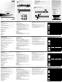
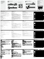
Hardware Review
A
Front View
1. Port LEDs
2. Port Selection Switches
3. IR Sensor
4. VGA Display On / Off LED
5. External IR Receiver Port
Rear View
1. Power Jack
2. Power Switch
3. Media Port Section
4. Monitor Port
5. Audio Jack
Conguration minimale
Périphérique d’afchage
• Un périphérique d'afchage VGA, SVGA, XGA, SXGA, UXGA, WUXGA ou
multisync ou un récepteur équipé d'un connecteur HDB-15
• Un mini-connecteur d’entrée audio stéréo (en option)
Périphérique(s) source
• Une carte vidéo analogique VGA, SVGA, XGA, SXGA, UXGA, WUXGA ou
Multisync dotée d’un connecteur de PC standard de type HDB-15 par ordinateur
• Un mini-connecteur de sortie audio stéréo (en option)
Câbles
• Un câble vidéo avec un connecteur mâle et un connecteur femelle HDB-15 à
chaque extrémité pour chaque ordinateur que vous installez.
• Un câble audio avec mini prise jack stéréo.
Remarque: cette unité est livrée avec un câble vidéo/audio.
Description de l’appareil
A
Vue avant
1. Voyants des ports
2. Commutateurs de sélection de port
3. Capteur infrarouge
4. Voyant Marche/Arrêt de l’écran VGA
5. Port du récepteur infrarouge externe
Vue arrière
1. Prise d’alimentation
2. Interrupteur
3. Section des ports multimédia
4. Port moniteur
5. Prise audio
Voraussetzungen
Anzeigegerät
• Ein VGA-, SVGA-, XGA-, SXGA-, UXGA-, WUXGA- oder MultiSync-
Anzeigegerät mit HDB-15-Eingang
• Ein Stereo-Mini-Klinkeneingang (optional)
Signalquelle(n)
• Eine analoge VGA-, SVGA-, XGA-, SXGA-, UXGA-, WUXGA- oder Multisync-
Grakkarte mit einer PC-Standard-Anschlussbuchse HDB-15 pro Computer
• Ein Stereo-Mini-Klinkenausgang (optional)
Kabel
• Ein Gra ksignalkabel mit je einem 15-poligen HDB-Stecker Männlein und
Weiblein für jeden Computer, den Sie installieren möchten.
• Ein Audiokabel mit Mini-Stereo-Stecker.
Hinweis: Ein Gra ksignalkabel / Audiokabel ist im Lieferumfang enthalten.
Hardwareübersicht
A
Vorderseitige Ansicht
1. Port-LEDs
2. Port-Auswahlschalter
3. Infrarotsensor
4. LED-Anzeige VGA-Display ein / aus
5. Port für externen Infrarot-Empfänger
Rückseitige Ansicht
1. Stromeingangsbuchse
2. Netzschalter
3. Media-Portabschnitt
4. Monitoranschluss
5. Audio-Buchse
Requisitos
Dispositivo de visualización
• Un dispositivo de visualización VGA, SVGA, XGA, SXGA, UXGA, WUXGA o
multisync o un receptor con un conector HDB-15
• Un miniconector de entrada de audio estéreo (opcional).
Dispositivo(s) fuente
• Una tarjeta gráca analógica VGA, SVGA, XGA, SXGA, UXGA, WUXGA o
Multisync para PC con salida HDB-15 hembra en cada computadora
• Un miniconector de salida de audio estéreo (opcional).
Cables
• Un cable de señal grá ca con un conector HDB-15 macho y uno hembra en
cada extremo para cada ordenador que vaya a instalar.
• Un cable de audio con clavija mini estéreo.
Nota: Esta unidad viene con un cable de señal grá ca/ audio.
Presentación del hardware
A
Vista frontal
1. Indicadores LED de los puertos
2. Conmutadores de selección de puertos
3. Sensor de infrarrojos
4. Indicador de pantalla VGA encendida/apagada
5. Puerto para receptor de infrarrojos externo
Vista posterior
1. Entrada de alimentación
2. Interruptor de alimentación
3. Sección de puertos para medios
4. Puerto de monitor
5. Conector de audio
IR Remote Control Unit
1. Port Up / Port Down
2. Port Selection
Hardware Installation
B
Note: Make sure that power to all the devices you will be connecting up have
been turned off.
1. Plug the monitor or digital projector cable into the unit's Monitor port.
2. Connect speakers to the unit’s audio output port.
3. Plug one end of a video cable into any available video port on the unit; plug
the other end into the computer's video output port.
Note: One video cable is supplied with this unit. Additional cables require an
extra purchase.
4. Use a male/male audio cable to connect the computer’s speaker output port
with the audio input port of the video port selected in step 3.
5. Repeat steps 3 and 4 for each computer you wish to install.
6. Plug the power adapter (supplied with this package) into an AC source, and
then plug the power adapter cable into the unit's Power Jack.
7. Plug the IR Receiver cable into the IR Receiver port at the front of the main
unit (this step is optional).
8. Power On all equipment.
Operation
Port Selection
Manual Port Up / Port Down
Use the Port Up and Port Down pushbuttons, located on the VS1601 unit, to
cycle the video focus to the port you want.
The selected port’s LED lights GREEN to indicate that the computer connected
to its corresponding port has the video focus.
Télécommande infrarouge
1. Port précédent / Port suivant
2. Sélection des ports
Installation du matériel
B
Remarque: Véri ez que tous les périphériques à connecter sont éteints.
1. Connectez le câble du moniteur ou du projecteur numérique au port moniteur
de l'unité.
2. Branchez les haut-parleurs sur le port de sortie audio de l'unité.
3. Branchez l'une des extrémités du câble vidéo à un port video libre de l'unité.
Branchez l'autre extrémité sur le port de sortie vidéo de l'ordinateur.
Remarque: cette unité est livrée avec un câble vidéo. Si besoin est, vous
pouvez vous procurer des câbles supplémentaires auprès de
votre distributeur.
4. Utilisez un câble audio mâle/mâle pour relier le port de sortie des haut-parleurs
de l'ordinateur au connecteur d'entrée audio du port graphique sélectionné à
l'étape 3.
5. Répétez les étapes 3 et 4 pour chaque ordinateur à installer.
6. Connectez l'adaptateur secteur fourni à la source d'alimentation CA, et le
câble de l'adaptateur à la prise jack d'alimentation de l'unité.
7. Branchez le câble du récepteur infrarouge sur le port correspondant situé à
l'avant de l'unité centrale (étape facultative).
8. Allumez tous les appareils.
Utilisation
Sélection de ports
Port suivant / précédent (sélection manuelle)
Utilisez les boutons Port Up (Port suivant) et Port Down (Port précédent), situés
sur l'unité VS1601, pour sélectionner le port de mise au point graphique désiré.
Infrarot-Fernbedienung
1. Port auf / Port ab
2. Portauswahl
Hardware installieren
B
Hinweis: Schalten Sie alle anzuschließenden Geräte aus.
1. Schließen Sie das Kabel des Monitors oder Projektors an den Monitor-Port
des Gerätes an.
2. Verbinden Sie die Lautsprecher mit dem Audioausgang des Gerätes.
3. Verbinden Sie das eine Ende des Gra ksignalkabels mit einem freien
Gra k-Port am Gerät; verbinden Sie das andere Ende mit dem Gra
kkartenausgang am Computer.
Hinweis: Ein Graksignalkabel ist im Lieferumfang enthalten. Zusätzliche
Kabel müssen separat erworben werden.
4. Verbinden Sie die Lautsprecherausgangsbuchse des Computers mit der
Audioeingangsbuchse des Gra kports, den Sie in Schritt 3 gewählt haben.
Verwenden Sie dazu ein Audiokabel Männlein/ Männlein.
5. Wiederholen Sie die Schritte 3 und 4 für alle weiteren Computer, die Sie
anschließen möchten.
6. Verbinden Sie das mitgelieferte Netzteil mit einer Steckdose und sein
Netzkabel mit der Stromeingangsbuchse des Gerätes.
7. Verbinden Sie das Kabel der Infrarot-Fernbedienung mit dem dafür
vorgesehenen Anschluss vorne am Gerät (dieser Schritt ist optional).
8. Schalten Sie alle Geräte ein.
Bedienung
Portauswahl
Manuell Port auf / Port ab
Drücken Sie die Tasten Port Up und Port Down am VS1601, um das Gra ksignal
auf den betreffenden Anschluss zu leiten.
Mando a distancia por infrarrojos
1. Puerto anterior/siguiente
2. Selección de puertos
Instalación del hardware
B
Nota: Apague todos los dispositivos que vaya a conectar.
1. Conecte el cable del monitor o del proyector digital al puerto de monitor de la
unidad.
2. Conecte los altavoces al puerto de salida de audio de la unidad.
3. Conecte un extremo del cable de señal grá ca a un puerto grá co libre de la
unidad. Conecte el otro extremo a la salida de la tarjeta grá ca del ordenador.
Nota: Esta unidad se suministra con un cable de señal gráca. Si fuera
necesario, puede adquirir cables adicionales de su distribuidor.
4. Use un cable de audio macho/macho para conectar la salida para altavoces
del ordenador al puerto de entrada de audio que corresponde al puerto de
entrada grá ca que conectó en el paso 3.
5. Repita los pasos 3 y 4 para todos los ordenadores que desee instalar.
6. Conecte el adaptador de alimentación incluido a una toma eléctrica, y el cable
del adaptador a la entrada de corriente de la unidad.
7. Conecte el cable del receptor de infrarrojos al Puerto correspondiente situado
en la parte anterior de la unidad principal (este paso es opcional).
8. Encienda todos los equipos.
Funcionamiento
Selección de puertos
Puerto siguiente/anterior (selección manual)
Utilice los botones Port Up (Puerto siguiente) y Port Down (Puerto anterior),
situados en la unidad VS1601, para seleccionar el Puerto grá co deseado.
IR Port Up / Port Down
The video focus can also be cycled among the computers using the Port Up and
Port Down buttons of the IR Remote Control Unit.
Note: The IR Remote Control Unit is used in conjunction with the external IR
Receiver.
IR Direct Port Selection
Instead of cycling among the individual computers one-by-one, a computer
can be directly selected by pushing the button on the Remote Control Unit that
corresponds to its port number (1-16) on the main unit.
The selected port's LED lights GREEN to indicate that the computer connected
to its corresponding port has the video focus.
Note: For optimum performance make sure that there is a clear line-of-site
between the handset and the receiver.
Le voyant du port sélectionné s'allume en vert pour indiquer que le signal
graphique provient de l'ordinateur connecté à son port.
Port suivant / précédent (sélection par infrarouge)
Vous pouvez également faire déler les ordinateurs à l'aide des boutons Port Up
et Port Down de la télécommande infrarouge.
Remarque: la télécommande s’utilise en conjonction avec le récepteur
infrarouge externe.
Sélection directe du port par infrarouge
Au lieu de faire dé ler les ordinateurs, vous pouvez en sélectionner un
directement en appuyant sur le bouton de la télécommande correspondant à son
numéro de port (1 à 16) sur l'unité principale.
Le voyant du port sélectionné s'allume en vert pour indiquer que l'ordinateur
connecté à son port correspondant dispose de la mise au point graphique.
Remarque: Pour des performances optimales, véri ez qu'aucun obstacle ne
se trouve entre la télécommande et le récepteur. clear line-of-site
between the handset and the receiver.
Die LED-Anzeige des ausgewählten Anschlusses leuchtet GRÜN, wenn
das Signal von dem Computer empfangen wird, der am betreffenden Port
angeschlossenen ist.
Fernbedienung Port auf / Port ab
Sie können das Graksignal der verschiedenen Computer auch über die Tasten
Port Up und Port Down der Fernbedienung umschalten.
Hinweis: Die Fernbedienung wird zusammen mit dem externen Infrarot-
Empfänger verwendet.
Direkte Portauswahl per Fernbedienung
Anstatt die verschiedenen Computeranschlüsse der Reihe nach durchzublättern,
können Sie auf der Fernbedienung auch direkt die Nummer (1 – 16) des
gewünschten Anschlusses eingeben.
Die LED-Anzeige des ausgewählten Anschlusses leuchtet GRÜN, wenn
das Signal von dem Computer empfangen wird, der am betreffenden Port
angeschlossenen ist.
Hinweis: Achten Sie darauf, dass sich keine Hindernisse im Ausbreitungspfad
zwischen Fernbedienung und Empfänger be nden.
El indicador LED del puerto seleccionado se ilumina de verde para indicar que la
señal gráca procede de la computadora conectada a su puerto.
Puerto siguiente/anterior (selección por infrarrojos)
Puede también seleccionar los ordenadores con los botones Port Up y Port
Down del mando a distancia de infrarrojos.
Nota: El mando a distancia funciona junto con el receptor por infrarrojos externo.
Selección directa del puerto por infrarrojos
En vez de seleccionar los ordenadores uno tras otro, puede seleccionar
directamente un ordenador pulsando el botón del mando a distancia que
corresponda a su número de puerto (1 a 16) en la unidad principal.
El indicador LED del puerto seleccionado se ilumina de verde para indicar que la
señal grá ca procede del ordenador conectado a su puerto.
Nota: Procure que no haya obstáculos en la trayectoria entre el mando a
distancia y el receptor.
VS881
Specications
Function VS1601
Computer Connections 16
Port Selection Pushbutton; IR Remote Control
Connectors
Video In 16 x HDB-15 Male (Blue)
Audio In 16 x Mini Stereo Jack Female (Green)
Video Out 1 x HDB-15 Female (Blue)
Audio Out 1 x Mini Stereo Jack Female (Green)
IR 1 x Mini Stereo Jack (Female)
Power 1 x DC Jack
LEDs
On Line / Selected 16 (Orange/Green)
Video Out Display
On/Off
1 (Blue)
Switches
Power 1 x Rocker
Port Up 1 x Pushbutton
Port Down 1 x Pushbutton
Video 1920 x 1440 @ 60Hz (max); DDC2B
Signal Range 65m
Power Consumption DC5V, 2.5W
Environment
Operating Temp. 0 – 50o C
Storage Temp. -20 – 60o C
Humidity 0 – 80% RH, Non-condensing
Physical
Properties
Housing Metal
Weight 2.60kg
Dimensions (L x W x H) 43.30 x 16.00 x 4.40 cm
Caractéristiques techniques
Fonction VS1601
Connexions à l'ordinateur 16
Sélection des ports
Bouton-poussoir ; télécommande
infrarouge
Connecteurs
Entrée vidéo 16 connecteurs HDB-15 mâles (bleus)
Entrée audio 16 mini-jacks stéréo femelles (verts)
Sortie vidéo 1 connecteur HDB-15 femelle (bleu)
Sortie audio 1 mini-jack stéréo femelle (vert)
Infrarouge (IR) 1 mini-jack stéréo (femelle)
Alimentation 1 prise d’alimentation CC
Voyants
En ligne/ Sélectionné 16 voyants (orange/vert)
Marche/Arrêt écran de
sortie vidéo
1 voyant (bleu)
Commutateurs
Alimentation 1 interrupteur à bascule
Port précédent 1 bouton-poussoir
Port suivant 1 bouton-poussoir
Vidéo 1920 x 1440 à 60 Hz (maxi) ; DDC2B
Portée du signal 65 m
Consommation électrique 5 Vcc - 2,5 W
Environnement
Température de
fonctionnement
0 à 50° C
Température de
stockage
-20 à 60° C
Humidité HR de 0 à 80 %, sans condensation
Propriétés
physiques
Boîtier Métallique
Poids 2,60 kg
Dimensions (Long x
Larg x Haut)
43,30 x 16,00 x 4,40 cm
Technische Daten
Funktion VS1601
Computeranschlüsse 16
Portauswahl Drucktaste, Infrarot-Fernbedienung
Anschlüsse
Grakeingänge 16 x HDB-15 Männlein (blau)
Audio-Eingänge
16 x Mini-Stereo-Buchse, Weiblein
(grün)
Grakausgänge 1 x HDB-15 Weiblein (blau)
Audio-Ausgang 1 x Mini-Stereo-Buchse, Weiblein (grün)
Infrarot 1 x Mini-Stereo-Buchse (Weiblein)
Stromversorgung 1 x Stromeingangsbuchse
LED-Anzeigen
Online/ausgewählt 16 (orange/grün)
Angeschlossenes VGA-
Display ein / aus
1 (blau)
Schalter
Ein/Aus 1 x Kippschalter
Voriger Port 1 x Drucktaste
Nächster Port 1 x Drucktaste
Grak 1920 x 1440 bei 60 Hz (max.); DDC2B
Signal-Reichweite 65 m
Stromverbrauch 5 V=, 2,5 W
Umgebung
Betriebstemperatur 0 – 50°C
Lagertemperatur -20 – 60°C
Feuchtigkeit
0 - 80% rel. Luftfeuchte, nicht
kondensierend
Physische
Eigenschaften
Gehäuse Metall
Gewicht 2,60 kg
Abmessungen
(L x B x H)
43,30 x 16,00 x 4,40 cm
Especicaciones
Función VS1601
Conexiones para computadoras 16
Selección de puertos Pulsador, mando a distancia por infrarrojos
Conectores
Entrada de señal gráca 16 conectores HDB-15 macho (azul)
Entrada de audio 16 conectores mini estéreo hembra (verde)
Salida de señal gráca 1 conector HDB-15 hembra (azul)
Salida de audio 1 conector mini estéreo hembra (verde)
Infrarrojos 1 clavija mini estéreo (hembra)
Alimentación 1 toma de c.c.
Indicadores
LED
En línea / Seleccionado 16 (anaranjado/verde)
Pantalla conectada
encendida/apagada
1 (azul)
Interruptores
Alimentación 1 basculante
Puerto anterior 1 pulsador
Puerto siguiente 1 pulsador
Señal gráca 1920 x 1440 a 60 Hz (máx.); DDC2B
Alcance de la señal 65 m
Consumo c.c. 5 V, 2,5 W
Entorno
Temperatura de
funcionamiento
0 a 50 °C
Temperatura de
almacenamiento
-20 a 60 °C
Humedad 0 a 80% HR, sin condensar
Propiedades
físicas
Carcasa Metálica
Peso 2,60 kg
Dimensiones
(L x An x Al)
43,30 x 16,00 x 4,40 cm
Hardware Installation
B
User Guide
16-Port Video Switch
VS1601
Front View
Rear View
IR Remote Control Unit
Package Contents
1 VS1601 Video Switch with Standard Rack Mounting Kit
1 VGA/Audio Cable (1.8 m)
1 IR Remote Control Unit
1 External IR receiver (1.8m)
1 Power Adapter
1 User Guide
The following contains information that relates to China:
Online Registration
International:
http://support.aten.com
North America:
http://www.aten-usa.com/product_
registration
Technical Phone Support
International:
886-2-86926959
North America:
1-888-999-ATEN Ext: 4988
United Kingdom:
44-8-4481-58923
FCC Information
This equipment has been tested and found to comply with
the limits for a Class B digital device, pursuant to Part 15
of the FCC Rules. These limits are designed to provide
reasonable protection against harmful interference in a
residential installation. This equipment generates, uses
and can radiate radio frequency energy, and if not installed
and used in accordance with the instruction manual, may
cause interference to radio communications. However,
there is no guarantee that interference will not occur in a
particular installation. If this equipment does cause harmful
interference to radio or television reception, which can be
determined by turning the equipment off and on, the user
is encouraged to try to correct the interference by one or
more of the following measures:
• Reorient or relocate the receiving antenna;
• Increase the separation between the equipment and
receiver;
• Connect the equipment into an outlet on a circuit different
from that which the receiver is connected;
• Consult the dealer/an experienced radio/television
technician for help.
All information, documentation, and specications contained
in this media are subject to change without prior notication
by the manufacturer. Please visit our website to nd the
most up to date version.
www.aten.com
www.aten.com
www.aten.com
www.aten.com
Hardware Review
A
1 2
4 5
3
1 2
4 5
3
1
2
Port Down
Port Up
1 2 3 4
5 6 7 8
9 0
ETR
Port selection
7
1
2
4
5
3
La página se está cargando...
Transcripción de documentos
A Hardware Review Front View 1 2 4 3 5 Rear View 1 FCC Information Package Contents 2 This equipment has been tested and found to comply with the limits for a Class B digital device, pursuant to Part 15 of the FCC Rules. These limits are designed to provide reasonable protection against harmful interference in a residential installation. This equipment generates, uses and can radiate radio frequency energy, and if not installed and used in accordance with the instruction manual, may cause interference to radio communications. However, there is no guarantee that interference will not occur in a particular installation. If this equipment does cause harmful interference to radio or television reception, which can be determined by turning the equipment off and on, the user is encouraged to try to correct the interference by one or more of the following measures: • Reorient or relocate the receiving antenna; • Increase the separation between the equipment and receiver; • Connect the equipment into an outlet on a circuit different from that which the receiver is connected; • Consult the dealer/an experienced radio/television technician for help. 1 VS1601 Video Switch with Standard Rack Mounting Kit 1 VGA/Audio Cable (1.8 m) 1 IR Remote Control Unit 1 External IR receiver (1.8m) 1 Power Adapter 1 User Guide B Hardware Installation 3 Online Registration International: http://support.aten.com North America: http://www.aten-usa.com/product_ registration 7 16-Port 8-Port Video Video Switch Switch VS1601 VS881 4 Technical Phone Support 5 IR Remote Control Unit User Guide International: 886-2-86926959 North America: 1-888-999-ATEN Ext: 4988 United Kingdom: 44-8-4481-58923 3 5 Port Up 1 The following contains information that relates to China: 4 Port Down Port selection © Copyright 2011 ATEN® International Co., Ltd. ATEN and the ATEN logo are trademarks of ATEN International Co., Ltd. All rights reserved. All other trademarks are the property of their respective owners. 2 This product is RoHS compliant. Part No. PAPE-1285-250G 1 2 3 4 5 6 7 8 9 0 1 2 All information, documentation, and specifications contained in this media are subject to change without prior notification by the manufacturer. Please visit our website to find the most up to date version. ETR Printing Date: 06/2011 VS1601 16-Port Video Switch User Guide www.aten.com Requirements IR Remote Control Unit Display Device • A VGA, SVGA, XGA, SXGA, UXGA,WUXGA, or multisync display device or receiver with an HDB-15 connector • A mini stereo audio input jack (optional) Source Device(s) • A VGA, SVGA, XGA, SXGA, UXGA,WUXGA, or Multisync analog video card having a standard PC HDB-15 connector per computer • A mini stereo audio output jack (optional) Cables • A video cable with one male and one female HDB-15 connector at each end for each computer you will be installing. • An audio cable with a Mini Stereo Jack. Note: One VGA/audio cable is supplied with this unit. Hardware Review A Front View 1. Port LEDs 2. Port Selection Switches 3. IR Sensor 4. VGA Display On / Off LED 5. External IR Receiver Port IR Port Up / Port Down The video focus can also be cycled among the computers using the Port Up and Port Down buttons of the IR Remote Control Unit. Note: The IR Remote Control Unit is used in conjunction with the external IR Receiver. 1. Port Up / Port Down 2. Port Selection Hardware Installation B Note: Make sure that power to all the devices you will be connecting up have been turned off. 1. Plug the monitor or digital projector cable into the unit's Monitor port. 2. Connect speakers to the unit’s audio output port. 3. Plug one end of a video cable into any available video port on the unit; plug the other end into the computer's video output port. Note: One video cable is supplied with this unit. Additional cables require an extra purchase. 4. Use a male/male audio cable to connect the computer’s speaker output port with the audio input port of the video port selected in step 3. 5. Repeat steps 3 and 4 for each computer you wish to install. 6. Plug the power adapter (supplied with this package) into an AC source, and then plug the power adapter cable into the unit's Power Jack. 7. Plug the IR Receiver cable into the IR Receiver port at the front of the main unit (this step is optional). 8. Power On all equipment. IR Direct Port Selection Instead of cycling among the individual computers one-by-one, a computer can be directly selected by pushing the button on the Remote Control Unit that corresponds to its port number (1-16) on the main unit. The selected port's LED lights GREEN to indicate that the computer connected to its corresponding port has the video focus. Note: For optimum performance make sure that there is a clear line-of-site between the handset and the receiver. Operation Port Selection Manual Port Up / Port Down Use the Port Up and Port Down pushbuttons, located on the VS1601 unit, to cycle the video focus to the port you want. The selected port’s LED lights GREEN to indicate that the computer connected to its corresponding port has the video focus. Rear View 1. Power Jack 2. Power Switch 3. Media Port Section 4. Monitor Port 5. Audio Jack Specifications Function Computer Connections Port Selection Video In Audio In Video Out Connectors Audio Out IR Power On Line / Selected LEDs Video Out Display On/Off Power Switches Port Up Port Down Video Signal Range Power Consumption Operating Temp. Environment Storage Temp. Humidity Housing Physical Weight Properties Dimensions (L x W x H) VS1601 16 Pushbutton; IR Remote Control 16 x HDB-15 Male (Blue) 16 x Mini Stereo Jack Female (Green) 1 x HDB-15 Female (Blue) 1 x Mini Stereo Jack Female (Green) 1 x Mini Stereo Jack (Female) 1 x DC Jack 16 (Orange/Green) 1 (Blue) 1 x Rocker 1 x Pushbutton 1 x Pushbutton 1920 x 1440 @ 60Hz (max); DDC2B 65m DC5V, 2.5W 0 – 50o C -20 – 60o C 0 – 80% RH, Non-condensing Metal 2.60kg 43.30 x 16.00 x 4.40 cm Commutateur vidéo à 16 ports VS1601 – Guide d’utilisation Configuration minimale Télécommande infrarouge Périphérique d’affichage • Un périphérique d'affichage VGA, SVGA, XGA, SXGA, UXGA, WUXGA ou multisync ou un récepteur équipé d'un connecteur HDB-15 • Un mini-connecteur d’entrée audio stéréo (en option) Périphérique(s) source • Une carte vidéo analogique VGA, SVGA, XGA, SXGA, UXGA, WUXGA ou Multisync dotée d’un connecteur de PC standard de type HDB-15 par ordinateur • Un mini-connecteur de sortie audio stéréo (en option) Câbles • Un câble vidéo avec un connecteur mâle et un connecteur femelle HDB-15 à chaque extrémité pour chaque ordinateur que vous installez. • Un câble audio avec mini prise jack stéréo. Remarque: cette unité est livrée avec un câble vidéo/audio. Description de l’appareil www.aten.com A Vue avant 1. Voyants des ports 2. Commutateurs de sélection de port 3. Capteur infrarouge 4. Voyant Marche/Arrêt de l’écran VGA 5. Port du récepteur infrarouge externe Le voyant du port sélectionné s'allume en vert pour indiquer que le signal graphique provient de l'ordinateur connecté à son port. 1. Port précédent / Port suivant 2. Sélection des ports Installation du matériel B Remarque: Vérifi ez que tous les périphériques à connecter sont éteints. 1. Connectez le câble du moniteur ou du projecteur numérique au port moniteur de l'unité. 2. Branchez les haut-parleurs sur le port de sortie audio de l'unité. 3. Branchez l'une des extrémités du câble vidéo à un port video libre de l'unité. Branchez l'autre extrémité sur le port de sortie vidéo de l'ordinateur. Remarque: cette unité est livrée avec un câble vidéo. Si besoin est, vous pouvez vous procurer des câbles supplémentaires auprès de votre distributeur. 4. Utilisez un câble audio mâle/mâle pour relier le port de sortie des haut-parleurs de l'ordinateur au connecteur d'entrée audio du port graphique sélectionné à l'étape 3. 5. Répétez les étapes 3 et 4 pour chaque ordinateur à installer. 6. Connectez l'adaptateur secteur fourni à la source d'alimentation CA, et le câble de l'adaptateur à la prise jack d'alimentation de l'unité. 7. Branchez le câble du récepteur infrarouge sur le port correspondant situé à l'avant de l'unité centrale (étape facultative). 8. Allumez tous les appareils. Port suivant / précédent (sélection par infrarouge) Vous pouvez également faire défiler les ordinateurs à l'aide des boutons Port Up et Port Down de la télécommande infrarouge. Remarque: la télécommande s’utilise en conjonction avec le récepteur infrarouge externe. Sélection directe du port par infrarouge Au lieu de faire défi ler les ordinateurs, vous pouvez en sélectionner un directement en appuyant sur le bouton de la télécommande correspondant à son numéro de port (1 à 16) sur l'unité principale. Le voyant du port sélectionné s'allume en vert pour indiquer que l'ordinateur connecté à son port correspondant dispose de la mise au point graphique. Remarque: Pour des performances optimales, vérifi ez qu'aucun obstacle ne se trouve entre la télécommande et le récepteur. clear line-of-site between the handset and the receiver. Utilisation Sélection de ports Vue arrière Port suivant / précédent (sélection manuelle) Utilisez les boutons Port Up (Port suivant) et Port Down (Port précédent), situés sur l'unité VS1601, pour sélectionner le port de mise au point graphique désiré. 1. Prise d’alimentation 2. Interrupteur 3. Section des ports multimédia 4. Port moniteur 5. Prise audio Caractéristiques techniques Fonction Connexions à l'ordinateur Sélection des ports Connecteurs Voyants Commutateurs Entrée vidéo Entrée audio Sortie vidéo Sortie audio Infrarouge (IR) Alimentation En ligne/ Sélectionné Marche/Arrêt écran de sortie vidéo Alimentation Port précédent Port suivant Vidéo Portée du signal Consommation électrique Température de fonctionnement Environnement Température de stockage Humidité Boîtier Propriétés Poids physiques Dimensions (Long x Larg x Haut) VS1601 16 Bouton-poussoir ; télécommande infrarouge 16 connecteurs HDB-15 mâles (bleus) 16 mini-jacks stéréo femelles (verts) 1 connecteur HDB-15 femelle (bleu) 1 mini-jack stéréo femelle (vert) 1 mini-jack stéréo (femelle) 1 prise d’alimentation CC 16 voyants (orange/vert) 1 voyant (bleu) 1 interrupteur à bascule 1 bouton-poussoir 1 bouton-poussoir 1920 x 1440 à 60 Hz (maxi) ; DDC2B 65 m 5 Vcc - 2,5 W 0 à 50° C -20 à 60° C HR de 0 à 80 %, sans condensation Métallique 2,60 kg 43,30 x 16,00 x 4,40 cm VS1601 16-Port-Grafik-Switch Benutzerhandbuch Voraussetzungen Infrarot-Fernbedienung Anzeigegerät • Ein VGA-, SVGA-, XGA-, SXGA-, UXGA-, WUXGA- oder MultiSyncAnzeigegerät mit HDB-15-Eingang • Ein Stereo-Mini-Klinkeneingang (optional) Signalquelle(n) • Eine analoge VGA-, SVGA-, XGA-, SXGA-, UXGA-, WUXGA- oder MultisyncGrafikkarte mit einer PC-Standard-Anschlussbuchse HDB-15 pro Computer • Ein Stereo-Mini-Klinkenausgang (optional) Kabel • Ein Grafi ksignalkabel mit je einem 15-poligen HDB-Stecker Männlein und Weiblein für jeden Computer, den Sie installieren möchten. • Ein Audiokabel mit Mini-Stereo-Stecker. Hinweis: Ein Grafi ksignalkabel / Audiokabel ist im Lieferumfang enthalten. Hardwareübersicht www.aten.com A Vorderseitige Ansicht 1. Port-LEDs 2. Port-Auswahlschalter 3. Infrarotsensor 4. LED-Anzeige VGA-Display ein / aus 5. Port für externen Infrarot-Empfänger Die LED-Anzeige des ausgewählten Anschlusses leuchtet GRÜN, wenn das Signal von dem Computer empfangen wird, der am betreffenden Port angeschlossenen ist. 1. Port auf / Port ab 2. Portauswahl Hardware installieren B Hinweis: Schalten Sie alle anzuschließenden Geräte aus. 1. Schließen Sie das Kabel des Monitors oder Projektors an den Monitor-Port des Gerätes an. 2. Verbinden Sie die Lautsprecher mit dem Audioausgang des Gerätes. 3. Verbinden Sie das eine Ende des Grafi ksignalkabels mit einem freien Grafi k-Port am Gerät; verbinden Sie das andere Ende mit dem Grafi kkartenausgang am Computer. Hinweis: Ein Grafiksignalkabel ist im Lieferumfang enthalten. Zusätzliche Kabel müssen separat erworben werden. 4. Verbinden Sie die Lautsprecherausgangsbuchse des Computers mit der Audioeingangsbuchse des Grafi kports, den Sie in Schritt 3 gewählt haben. Verwenden Sie dazu ein Audiokabel Männlein/ Männlein. 5. Wiederholen Sie die Schritte 3 und 4 für alle weiteren Computer, die Sie anschließen möchten. 6. Verbinden Sie das mitgelieferte Netzteil mit einer Steckdose und sein Netzkabel mit der Stromeingangsbuchse des Gerätes. 7. Verbinden Sie das Kabel der Infrarot-Fernbedienung mit dem dafür vorgesehenen Anschluss vorne am Gerät (dieser Schritt ist optional). 8. Schalten Sie alle Geräte ein. Fernbedienung Port auf / Port ab Sie können das Grafiksignal der verschiedenen Computer auch über die Tasten Port Up und Port Down der Fernbedienung umschalten. Hinweis: Die Fernbedienung wird zusammen mit dem externen InfrarotEmpfänger verwendet. Direkte Portauswahl per Fernbedienung Anstatt die verschiedenen Computeranschlüsse der Reihe nach durchzublättern, können Sie auf der Fernbedienung auch direkt die Nummer (1 – 16) des gewünschten Anschlusses eingeben. Die LED-Anzeige des ausgewählten Anschlusses leuchtet GRÜN, wenn das Signal von dem Computer empfangen wird, der am betreffenden Port angeschlossenen ist. Hinweis: Achten Sie darauf, dass sich keine Hindernisse im Ausbreitungspfad zwischen Fernbedienung und Empfänger befi nden. Bedienung Rückseitige Ansicht Portauswahl 1. Stromeingangsbuchse 2. Netzschalter 3. Media-Portabschnitt 4. Monitoranschluss 5. Audio-Buchse Technische Daten Funktion Computeranschlüsse Portauswahl Grafikeingänge Audio-Eingänge Anschlüsse LED-Anzeigen Schalter Grafik Signal-Reichweite Stromverbrauch Betriebstemperatur Lagertemperatur Umgebung Feuchtigkeit Physische Eigenschaften Manuell Port auf / Port ab Drücken Sie die Tasten Port Up und Port Down am VS1601, um das Grafi ksignal auf den betreffenden Anschluss zu leiten. Grafikausgänge Audio-Ausgang Infrarot Stromversorgung Online/ausgewählt Angeschlossenes VGADisplay ein / aus Ein/Aus Voriger Port Nächster Port Gehäuse Gewicht Abmessungen (L x B x H) VS1601 Conmutador gráfico de 16 puertos Manual del usuario Requisitos • Un dispositivo de visualización VGA, SVGA, XGA, SXGA, UXGA, WUXGA o multisync o un receptor con un conector HDB-15 • Un miniconector de entrada de audio estéreo (opcional). Dispositivo(s) fuente • Una tarjeta gráfica analógica VGA, SVGA, XGA, SXGA, UXGA, WUXGA o Multisync para PC con salida HDB-15 hembra en cada computadora • Un miniconector de salida de audio estéreo (opcional). Cables • Un cable de señal gráfi ca con un conector HDB-15 macho y uno hembra en cada extremo para cada ordenador que vaya a instalar. • Un cable de audio con clavija mini estéreo. Nota: Esta unidad viene con un cable de señal gráfi ca/ audio. Presentación del hardware Vista frontal A 1. Indicadores LED de los puertos 2. Conmutadores de selección de puertos 3. Sensor de infrarrojos 4. Indicador de pantalla VGA encendida/apagada 5. Puerto para receptor de infrarrojos externo Vista posterior 1. Entrada de alimentación 2. Interruptor de alimentación 3. Sección de puertos para medios 4. Puerto de monitor 5. Conector de audio 1 (blau) 1 x Kippschalter 1 x Drucktaste 1 x Drucktaste 1920 x 1440 bei 60 Hz (max.); DDC2B 65 m 5 V=, 2,5 W 0 – 50°C -20 – 60°C 0 - 80% rel. Luftfeuchte, nicht kondensierend Metall 2,60 kg 43,30 x 16,00 x 4,40 cm www.aten.com Mando a distancia por infrarrojos Dispositivo de visualización VS1601 16 Drucktaste, Infrarot-Fernbedienung 16 x HDB-15 Männlein (blau) 16 x Mini-Stereo-Buchse, Weiblein (grün) 1 x HDB-15 Weiblein (blau) 1 x Mini-Stereo-Buchse, Weiblein (grün) 1 x Mini-Stereo-Buchse (Weiblein) 1 x Stromeingangsbuchse 16 (orange/grün) El indicador LED del puerto seleccionado se ilumina de verde para indicar que la señal gráfica procede de la computadora conectada a su puerto. 1. Puerto anterior/siguiente 2. Selección de puertos Instalación del hardware B Nota: Apague todos los dispositivos que vaya a conectar. 1. Conecte el cable del monitor o del proyector digital al puerto de monitor de la unidad. 2. Conecte los altavoces al puerto de salida de audio de la unidad. 3. Conecte un extremo del cable de señal gráfi ca a un puerto gráfi co libre de la unidad. Conecte el otro extremo a la salida de la tarjeta gráfi ca del ordenador. Nota: Esta unidad se suministra con un cable de señal gráfica. Si fuera necesario, puede adquirir cables adicionales de su distribuidor. 4. Use un cable de audio macho/macho para conectar la salida para altavoces del ordenador al puerto de entrada de audio que corresponde al puerto de entrada gráfi ca que conectó en el paso 3. 5. Repita los pasos 3 y 4 para todos los ordenadores que desee instalar. 6. Conecte el adaptador de alimentación incluido a una toma eléctrica, y el cable del adaptador a la entrada de corriente de la unidad. 7. Conecte el cable del receptor de infrarrojos al Puerto correspondiente situado en la parte anterior de la unidad principal (este paso es opcional). 8. Encienda todos los equipos. Funcionamiento Selección de puertos Puerto siguiente/anterior (selección manual) Utilice los botones Port Up (Puerto siguiente) y Port Down (Puerto anterior), situados en la unidad VS1601, para seleccionar el Puerto gráfi co deseado. Puerto siguiente/anterior (selección por infrarrojos) Puede también seleccionar los ordenadores con los botones Port Up y Port Down del mando a distancia de infrarrojos. Nota: El mando a distancia funciona junto con el receptor por infrarrojos externo. Selección directa del puerto por infrarrojos En vez de seleccionar los ordenadores uno tras otro, puede seleccionar directamente un ordenador pulsando el botón del mando a distancia que corresponda a su número de puerto (1 a 16) en la unidad principal. El indicador LED del puerto seleccionado se ilumina de verde para indicar que la señal gráfi ca procede del ordenador conectado a su puerto. Nota: Procure que no haya obstáculos en la trayectoria entre el mando a distancia y el receptor. Especificaciones Función VS1601 Conexiones para computadoras 16 Selección de puertos Pulsador, mando a distancia por infrarrojos Entrada de señal gráfica 16 conectores HDB-15 macho (azul) Entrada de audio 16 conectores mini estéreo hembra (verde) Salida de señal gráfica 1 conector HDB-15 hembra (azul) Conectores Salida de audio 1 conector mini estéreo hembra (verde) Infrarrojos 1 clavija mini estéreo (hembra) Alimentación 1 toma de c.c. En línea / Seleccionado 16 (anaranjado/verde) Indicadores Pantalla conectada LED 1 (azul) encendida/apagada Alimentación 1 basculante Interruptores Puerto anterior 1 pulsador Puerto siguiente 1 pulsador Señal gráfica 1920 x 1440 a 60 Hz (máx.); DDC2B Alcance de la señal 65 m Consumo c.c. 5 V, 2,5 W Temperatura de 0 a 50 °C funcionamiento Temperatura de Entorno -20 a 60 °C almacenamiento Humedad 0 a 80% HR, sin condensar Carcasa Metálica Propiedades Peso 2,60 kg físicas Dimensiones 43,30 x 16,00 x 4,40 cm (L x An x Al)-
 1
1
-
 2
2


ATEN VS1601 Guía de inicio rápido
- Categoría
- Telefonos
- Tipo
- Guía de inicio rápido
en otros idiomas
- français: ATEN VS1601 Guide de démarrage rapide
- italiano: ATEN VS1601 Guida Rapida
- English: ATEN VS1601 Quick start guide
- Deutsch: ATEN VS1601 Schnellstartanleitung
- 日本語: ATEN VS1601 クイックスタートガイド
Artículos relacionados
-
ATEN VS0801 Guía de inicio rápido
-
-
ATEN VE500RQ Guía de inicio rápido
-
ATEN VE300T Guía de inicio rápido
-
-
ATEN CE100 Manual de usuario
-
-
ATEN VS1508 Guía de inicio rápido
-
ATEN VE200R Guía de inicio rápido
-
ATEN VS1208T Guía de inicio rápido