
Motorola M930
Car Phone
Installation Guide
Manuel d’installation
Installationsanleitung
Guida all'installazione
Guía de instalación
Installatiehandleiding
Руководство по установке
GB
F
D A
I
E
NL
RU
M930.IG.book Page 1 Wednesday, March 7, 2007 2:00 PM

M930.IG.book Page 2 Wednesday, March 7, 2007 2:00 PM

Motorola Propietary
1
GB
Car Phone Installation Guide
Product parts
Head Control unit
Swivel
Holder
GPS Antenna
(M800 only)
Speaker
Power Cable
AUX +12V GND MUTE IGN
2A Fuses
Antenna
(Optional)
Microphone
Octopus Control
Cable
Privacy
Handset +
Holder
(Optional)
M930.IG.book Page 1 Wednesday, March 7, 2007 2:00 PM

Motorola Propietary
2
GB
Head control unit
When installing the fixed mobile car phone avoid positioning the head control unit where
it may disrupt the proper operation of the vehicle and/or its components, such as car
stereo, air bags, cubbyhole, glove compartments, ashtray, lighter, gear stick, hand brake,
etc....
Attach the car phone to a stable surface, in a position that is safe and convenient for the
driver to use.
Special warning:
Do not position the head control unit in front of the air bag or where it
may impair air bag performance, as the air bag might inflate in an accident and cause
damage.
Verify that the control unit does not face the sun or source of humidity, such as air
conditioner vents.
When the phone is powered off insert the SIM into socket at the right side of the phone
(M900, M930 only).
Swivel Holder
M930.IG.book Page 2 Wednesday, March 7, 2007 2:00 PM

Motorola Propietary
3
GB
Microphone
Install the microphone at a distance of no more
than 30 cm (12 inch) away from the driver’s
mouth, ideally on the upper right hand side of the
sun visor and away from any noise source such as
windscreens, window, fan/air conditioner, car
stereo etc.
Make sure the microphone is at a distance of at
least 1.5 m (4.9 ft) from the speaker and is not
directed towards the speaker.
Make sure that the microphone is correctly
positioned. See picture below for microphone
position.
Do not thread the microphone cable close to antenna cable, to avoid audio interference.
Plug the microphone cable into the compatible connection in the octopus control cable.
Important:
Make sure that the microphone cable does not come in contact and does not
interfere with the steering wheel and/or the pedals of the vehicle.
Attention!
The speaker and microphone (which is fitted on the sun visor above the driver)
should be pointed towards
opposite directions
to avoid echo.
Microphone location
Slot towards the driver
M930.IG.book Page 3 Wednesday, March 7, 2007 2:00 PM

Motorola Propietary
4
GB
Speaker
Install the speaker on the side of the central console, ideally alongside the legs of the
passenger sitting beside the driver, as far as possible from the microphone.
Thread the speaker cable under the carpet along the floor of the vehicle.
Plug the speaker cable into the compatible connection in the octopus control cable.
Verfiy that the cable does not interfere with the proper operation of the vehicle and/or its
componets.
Do not conceal the speaker behind any obstacle such as dashboard, glove compartment,
carpet or any other barrier which will result in bad audio quality.
Attention!
The speaker and microphone (which is fitted on the sun visor above the driver)
should be pointed towards
opposite directions
to avoid echo, speaker slots should be
pointed towards passenger door.
speaker location
M930.IG.book Page 4 Wednesday, March 7, 2007 2:00 PM

Motorola Propietary
5
GB
RF Antenna
On-glass antenna specifications
M900, M930 (GSM):
Frequency band: 900+1800MHz (850+ 1900MHz)
VSWR:Tx<=1.5:1 ; Rx <=2:1
Gain: 3dBi @ 900MHz & 2dBi @ 1800MHz (3dBi @
850MHz & 2dBi @ 1900MHz)
Recommended antenna:
(1) 900/1800MHz, GDE-5M, Mfr. Panorama
Antenna, UK
(2) 850/1900MHz. APDM928M, Mfr. PC-TEL
Antenna Product USA, Part Number Z2307
M800 (CDMA):
Frequency band: 800+1900MHz
VSWR:Tx<=1.5:1; Rx <=2:1
Gain: 3dBi @ 850 MHz & 2dBi @ 1900MHz
Recommended antenna:
(1) 850/1900MHz, APDM928M, Mfr. PCTEL Antenna Product USA
Additional Information
RF Cable: RG58U, PVC coated / polyethylene dialeptic cable, length 5M
RF Connector: M800, M900 (900/1800), M930 (900/1800): Mini UHF Male
M900 (850/1900), M930 (850/1900): SMA Male
Radiator and Foot cover: The following environmental parameters are mandatory:
Operating temperature: -30°C to +85°C
Heat and UV stabilised
Flammability UL94V0
Adhesive pads: Operating temperature: -40°C to +90°C and bond not effected by
moisture.
Attention!
Ensure the antenna is located at least 20 cm from driver or passengers.
M930.IG.book Page 5 Wednesday, March 7, 2007 2:00 PM

Motorola Propietary
6
GB
Antenna Installation
The preferred position for the antenna is on the upper right side of the windshield
Should another cellular device already be installed in the vehicle, the antennas should be
located at a distance of at least 30 cm (1ft) from each other.
Remember:
In certain car models (such as “Renault Megane” and “Renault Kangoo”), the
anterior windshield has a radiation filter, and therefore it is necessary to paste the antenna
in the side or rear windshield only.
Remember:
Do not thread the antenna cable close to the microphone cable to avoid
audio interference.
Use original antenna plug and clamping tools only.
Test antenna and cable performance using a VSWR meter.
Note:
In certain M800 models there is a GPS connection to be used with 4V external
active GPS antenna for navigation services
M930.IG.book Page 6 Wednesday, March 7, 2007 2:00 PM

Motorola Propietary
7
GB
Cable connections
Power
Connect the
RED
wire to a positive (+) 12V pole for steady power supply. Ensure the use
of a 2A/250V fuse.
Ground
Connect the
BLACK
wire to a negative pole (-) in the vehicle body. Ensure the use of a 2A/
250V fuse.
Ignition
Connect the
GREEN
wire to car IGN voltage and check the appropriate voltage using
voltmeter. This connection switches the phone on when turning the ignition on and it
switches the phone off when turning the ignition off. Ensure the use of a 2A/250V fuse.
Entertainment Mute
Connect the
ORANGE
wire to the car stereo system entertainment mute connection to
mute the stereo system when receiving or dialling a call.
*Ent. Mute is an optional feature
Auxiliary alert
Connect the
WHITE
wire to the car's horn and/or to the car's light connection to turn on
the lights and/or to activate the horn when receiving a call.
*Aux. Alert is an optional feature
*Certain M800 models have a 3-wire connection, without Auxiliary alert and enterainment mute wires.
M930.IG.book Page 7 Wednesday, March 7, 2007 2:00 PM

Motorola Propietary
8
GB
Cable connections (continue)
Entertainment Mute & Auxiliary Alert - open collector connections
M800/M900/M930
Command signal
12V
Relay
Common
Normally
Close
Normally
Open
Connect to white wire (for Aux.
Alert) or to orange wire (for
Ent. Mute)
AUX +12V GND MUTE IGN
2A Fuses
M930.IG.book Page 8 Wednesday, March 7, 2007 2:00 PM

Motorola Propietary
9
GB
Heavy vehicles with 24v
When installing the Fixed Mobile Car Phone in trucks or in any other heavy vehicle with 24
volt battery, connect the RED wire via 24VDC to 12VDC (50W) voltage converter.
The Ignition line (GREEN) in M900 & M930 can be connected directly to the truck ignition
switch (24V) and in M800
must
be connected to 12V only.
Data connection/maintenance cable
The Data connection wire in M800 and the mini USB connection in M900 & M930 enable
using the fixed mobile car phone as a modem or to synchronise data with external
computers using Motorola MPT program.
The data connections also enable authorised technicians to maintain the fixed mobile car
phone for technical service purposes (Software programming).
Mini USB
Connection
(M900 & M930
only)
Octopus control
cable
Data cable
M930.IG.book Page 9 Wednesday, March 7, 2007 2:00 PM

Motorola Propietary
10
GB
Connections summary
Wire colour Function Connect to... Ensure...
RED To supply steady (+)
power source.
12V steady power.
An additional fuse is
supplied that must be
connected to the
positive (+) pole.
The use of a 2A/250V
fuse.
BLACK To supply steady (-)
power source.
Vehicle body That the contact point
is only connected to
the vehicle body.
GREEN To switch the phone
on when the car
ignition is turned on,
and off when the car
ignition is turned off.
IGN voltage The appropriate
voltage using
voltmeter. Ensure the
use of a 2A/250V fuse.
ORANGE To mute the car stereo
system when
receiving or dialling a
call.
Car stereo system
Entertainment Mute
connection (optional)
That the connection
between the Fixed
Mobile Car Phone and
car stereo system
should be done by an
authorised installer
only, sink shoud be up
to 150mA.
WHITE To operate car lights/
horn to indicate
incoming call.
Car lights/horn
connections (optional)
That the connection
between the Fixed
Mobile Car Phone and
the car lights/horn
should be done by an
authorised installer
only, sink shoud be up
to 300mA.
M930.IG.book Page 10 Wednesday, March 7, 2007 2:00 PM

Motorola Propietary
11
GB
Privacy Handset/Headset
Mount the privacy handset using the plastic base and connect the handset jack to the
socket at the bottom of the main control unit.
Attach the privacy handset cable to the head control unit's holder using plastic strip.
Handset
base
Handset
base mount
Unit Holder
Plastic Strip
Verify that the
cable is not tight
M930.IG.book Page 11 Wednesday, March 7, 2007 2:00 PM

Motorola Propietary
12
GB
Special functions
Smart Key
The Smart Key is the blue illuminated key on the top side of the main control unit. This
special button, designed as a mouse key is a multiple operations button which enables
the user to voice activate Name & Number dialling, notice incoming calls, record voice
memos and end or receive phone calls by clicking on the button once.
Volume keys
The volume keys, located on the left hand side of the main control unit enable the users to
adjust audio volume during a call and to adjust the ringer volume during stand by. While
installing the phone in the vehicle don't place the main control unit close to the car
dashboard or to any other component that might interrupt with the volume keys
operation.
Soft keys and shortcuts
The two soft keys located on the lower part of the phone display enable users to
customise their phone and set useful menus for their convenience and intuitive location
on their phone display.
The navigation key enables the users to launch pre-defined menus (phone book, browser,
volume level setup) in a very quick and intuitive way instead of entering the phone
menus. The navigation key setup may vary from model to model.
Smart key
Soft keys
Navigation key
Volume keys
M930.IG.book Page 12 Wednesday, March 7, 2007 2:00 PM

Propriété Motorola
1
F
Guide d’installation du téléphone de véhicule
Composants
Téléphone (unité de
commande principale)
Support
Antenne GPS (M800
uniquement)
Haut-parleur
Câble d’alimentation
AUX +12V GND MUTE IGN
Fusibles 2A
Antenne (en
option)
Micro
Câble de commande
multiple
Support +
combiné
additionnel (en
option)
M930.IG.book Page 1 Wednesday, March 7, 2007 2:00 PM

Propriété Motorola
2
F
Téléphone (unité de
commande principale)
Pour l’installation de ce type d’appareil, évitez de placer le téléphone là où il pourrait
gêner le fonctionnement du véhicule et/ou de ses composants, comme la stéréo du
véhicule, les airbags, le vide-poches, la boîte à gants, le cendrier, l'allume-cigare, le levier
de vitesse, le frein à main, etc ...
Fixez le téléphone sur une surface stable, dans une position fiable et pratique pour le
conducteur.
Avertissement particulier :
N’installez pas le téléphone à l’avant de l'airbag ou dans tout
endroit susceptible de bloquer le fonctionnement approprié de celui-ci. En cas d’accident,
il peut se gonfler ce qui provoquerait des dommages.
S'assurez que le téléphone (unité de commande) ne soit pas face au soleil ou à toute
source d’humidité, comme les sorties d'air de climatisation.
Avec le téléphone éteint, insérez la carte SIM dans son logement sur le côté droit du
téléphone (M900, M930 uniquement).
Support
M930.IG.book Page 2 Wednesday, March 7, 2007 2:00 PM

Propriété Motorola
3
F
Micro
Installez le micro à moins de 30 cm de la bouche
du conducteur, l’idéal étant le côté droit supérieur
du pare-soleil et dans un endroit éloigné des
sources de bruit comme le pare-brise, les glaces,
le ventilateur/climatiseur, la stéréo du véhicule, etc
…
Assurez-vous que le micro est au moins à 1,5 m du
haut-parleur et n’est pas dirigé vers le haut-parleur.
Assurez-vous que le micro est correctement
installé. Voir l’illustration ci-dessous pour
l’installation du micro.
Ne placez pas le câble du micro près du câble de l’antenne, ceci afin d’éviter les parasites.
Branchez le câble du micro dans le connecteur approprié du câble de commande
multiple.
Important :
assurez-vous que le câble du micro ne touche pas et ne gêne pas le volant et/
ou les pédales du véhicule.
Attention !
le haut-parleur et le micro (installé sur le pare-soleil au-dessus du conducteur)
doivent être orientés
à l’opposé
l’un de l’autre pour éviter un écho.
Emplacement du micro
Fentes vers le
conducteur
M930.IG.book Page 3 Wednesday, March 7, 2007 2:00 PM

Propriété Motorola
4
F
Haut-parleur
Installez le haut-parleur sur le côté de la console centrale, l'idéal étant le long des jambes
du passager assis derrière le conducteur, et le plus loin possible du micro.
Passez le câble du haut-parleur sous le tapis le long du plancher du véhicule.
Branchez le câble du haut-parleur dans le connecteur approprié du câble de commande
multiple.
Assurez-vous que le câble ne gêne pas le fonctionnement du véhicule et/ou de ses
composants.
Ne dissimulez pas le haut-parleur derrière un obstacle comme le tableau de bord, la boîte
à gants, le tapis, etc. qui pourraient avoir des conséquences négatives sur la qualité du
son.
Attention !
le haut-parleur et le micro (installé sur le pare-soleil au-dessus du conducteur)
doivent être orientés
à l’opposé
l’un de l’autre pour éviter un écho, les fentes du haut-
parleur doivent être orientées vers la porte du passager.
Emplacement du haut-parleur
M930.IG.book Page 4 Wednesday, March 7, 2007 2:00 PM

Propriété Motorola
5
F
Antenne RF
Caractéristiques de l’antenne montée sur
glace
M900, M930 (GSM) :
Bande de fréquence : 900+1800MHz (850+ 1900MHz)
VSWR :Tx<=1.5:1 ; Rx <=2:1
Gain : 3dBi @ 900MHz & 2dBi @ 1800MHz (3dBi @
850MHz & 2dBi @ 1900MHz)
Antenne recommandée :
(1) 900/1800MHz, GDE-5M, Mfr. Antenne Panorama, UK
(2) 850/1900MHz. APDM928M, Mfr. PC-TEL
Antenne, production États-Unis, Numéro de pièce Z2307
M800 (CDMA) :
Bande de fréquence : 800+1900MHz
VSWR :Tx<=1.5:1 ; Rx <=2:1
Gain : 3dBi @ 850 MHz & 2dBi @ 1900MHz
Antenne recommandée :
(1) 850/1900MHz, APDM928M, Mfr. PCTEL Antenne, production États-Unis
Détails supplémentaires
Câble RF : RG58U, câble enduit PVC / polyéthylène, longueur 5 m
Connecteur RF :M800, M900 (900/1800), M930 (900/1800) : Mini UHF Mâle
M900 (850/1900), M930 (850/1900) : mâle SMA
Radiateur et couvre-pieds :les paramètres suivant concernant le milieu sont obligatoires :
Température de fonctionnement de -30 °C à +85 °C
Stabilité aux UV et à la chaleur
Inflammabilité UL94V0
Tampons adhésifs : température de fonctionnement : de -40 °C à +90 °C et résistance à
l’humidité.
Attention !
Assurez-vous que l’antenne se trouve à au moins 20 cm du conducteur et des
passagers.
M930.IG.book Page 5 Wednesday, March 7, 2007 2:00 PM

Propriété Motorola
6
F
Installation de l’antenne
L’endroit idéal pour installer l’antenne se trouve sur le côté droit supérieur du pare-brise
Si un autre périphérique cellulaire est déjà installé dans le véhicule, les antennes doivent
être espacées d’au moins 30 cm l’une de l’autre.
Rappel :
sur certains modèles de véhicule (comme « Renault Megane » et « Renault
Kangoo »), le pare-brise avant a un filtre anti-rayonnement. Il faut donc coller l’antenne
sur le côté ou sur le pare-brise arrière.
Rappel :
Ne placez pas le câble de l’antenne près du câble du micro, ceci afin d’éviter les
parasites.
N’utilisez que les outils de serrage et la prise d’antenne d’origine.
Testez le câble et l’antenne avec un appareil de mesure VSWR.
Remarque :
certains modèles M800 ont une connexion GPS qui est utilisée avec une
antenne GPS active externe 4V pour les options de navigation.
M930.IG.book Page 6 Wednesday, March 7, 2007 2:00 PM

Propriété Motorola
7
F
Connexions de câble
Alimentation
Branchez le fil
ROUGE
à un pôle positif (+) 12V pour un courant continu. Assurez-vous
que le fusible utilisé est un fusible de 2A/250V.
Masse
Branchez le fil
NOIR
à un pôle négatif (-) de la carrosserie du véhicule. Assurez-vous que
le fusible utilisé est un fusible de 2A/250V.
Allumage
Branchez le fil
VERT
à la tension IGN du véhicule et vérifiez si la tension est correcte avec
un voltmètre. Cette connexion allume le téléphone en mettant le contact et l’éteint en
coupant le contact. Assurez-vous que le fusible utilisé est un fusible de 2A/250V.
Mise en sourdine du module de divertissement
Branchez le fil
ORANGE
à la connexion de mise en sourdine du module de divertissement
du véhicule ceci afin d’interrompre la musique quand un appel est reçu ou émis.
*La mise en sourdine est une option.
Alerte auxiliaire
Branchez le fil
BLANC
à la connexion du klaxon et/ou des feux du véhicule ceci afin
d’allumer les feux et/ou de faire retentir le klaxon quand un appel est reçu.
*L’alerte auxiliaire est une option
*Certains modèles M800 ont une connexion à 3 fils, sans fil pour l’alerte auxiliaire et la mise en sourdine du module de divertissement.
M930.IG.book Page 7 Wednesday, March 7, 2007 2:00 PM

Propriété Motorola
8
F
Connexions de câble (suite)
Mise en sourdine du module de divertissement et alerte auxiliaire – ouverture des
connexions du collecteur
M800/M900/M930
Signal de commande
12V
Relais
Commun
Normalement
fermé
Normalement
ouvert
Branchement au fil blanc (pour
l’alerte auxiliaire) ou au fil
orange (pour mise en
sourdine)
AUX +12V GND MUTE IGN
Fusibles 2A
M930.IG.book Page 8 Wednesday, March 7, 2007 2:00 PM

Propriété Motorola
9
F
Poids lourds avec 24V
Pour l’installation de ce type d’appareil dans des camions ou autres poids lourds munis
d’une batterie 24V, branchez le fil ROUGE via le convertisseur de courant de 24VCC à
12VCC.
La ligne d’allumage (VERTE) du M900 et M930 doit être directement connectée au
commutateur d’allumage (24V) du camion et celle du M800
doit
être connectée sur du
12V uniquement.
Câble de maintenance/connexion de données
Le fil de connexion de données pour le M800 et la connexion mini-USB pour le M900 et le
M930 permettent d’utiliser un téléphone cellulaire fixe pour véhicule comme modem ou
de synchroniser des données avec des ordinateurs externes utilisant le programme
Motorola MPT.
Les connexions de données permettent aussi aux techniciens agréés d’effectuer les
entretiens techniques du téléphone (programmation du logiciel).
Connexion mini-
USB (M900 et
M930
uniquement)
Câble de
commande
multiple
Câble de
données
M930.IG.book Page 9 Wednesday, March 7, 2007 2:00 PM

Propriété Motorola
10
F
Résumé
Couleur de fil Fonction Connecter … Vérifier …
ROUGE Pour une source
d'alimentation de
courant continu (+).
Courant régulier 12V
Un fusible
supplémentaire est
alimenté et doit être
connecté au pôle
positif (+).
Le fusible utilisé doit être
un fusible de 2A/250V.
NOIR Pour une source
d'alimentation de
courant continu (-).
Carrosserie du
véhicule
Le point de contact n’est
connecté qu’à la
carrosserie.
VERT Pour allumer le
téléphone en
mettant le contact du
véhicule et l’éteindre
en coupant le
contact.
Tension IGN La tension avec un
voltmètre. Le fusible
utilisé doit être un fusible
de 2A/250V.
ORANGE Pour mettre en
sourdine la musique
quand un appel est
reçu ou émis.
Connexion de mise
en sourdine du
module de
divertissement du
véhicule (option)
Que la connexion entre le
téléphone cellulaire fixe
pour véhicule et le
module de
divertissement du
véhicule soit établie par
un installateur agréé
uniquement, absorption
de courant jusqu’à 150
mA.
BLANC Pour faire
fonctionner les
phares/klaxon afin
d’indiquer un appel
entrant.
Connexions des
phares/klaxon
(option)
Que la connexion entre le
téléphone cellulaire fixe
pour véhicule et le
module de
divertissement du
véhicule soit faite par un
installateur agréé
uniquement, l’absorption
de courant doit aller
jusqu’à 150 mA.
M930.IG.book Page 10 Wednesday, March 7, 2007 2:00 PM

Propriété Motorola
11
F
Écouteur/combiné additionnel
Installez le combiné additionnel sur la base en plastique et branchez la prise du kit en bas
sur le téléphone.
Reliez le câble du combiné additionnel au support du téléphone en utilisant la bande en
plastique.
Base du
combiné
additionnel
Support de base
du combiné
additionnel
Support du téléphone
Bande de plastique
Le câble ne doit
pas être trop serré
M930.IG.book Page 11 Wednesday, March 7, 2007 2:00 PM

Propriété Motorola
12
F
Fonctions spéciales
Bouton malin
Le bouton malin correspond à la touche bleue sur le côté en haut du téléphone. Ce
bouton spécial, conçu comme une souris peut exécuter plusieurs fonctions qui
permettent à l’utilisateur de composer vocalement un numéro ou un nom, de noter les
appels entrants, d’enregistrer des mémos vocaux et de mettre fin ou de recevoir des
appels en cliquant une fois sur le bouton.
Touches de volume
Les touches de volume, situées à gauche sur le téléphone permettent aux utilisateurs de
régler le volume pendant un appel et de régler le volume de la sonnerie en mode veille.
Pour l’installation de ce type d’appareil dans le véhicule, ne placez pas le téléphone sur le
tableau de bord ou sur tout autre composant qui pourraît être affectés lors de la
manipulations des touches de volume.
Touches programmables et raccourcis
Les deux touches programmables, se trouvant en bas de l’écran du téléphone permettent
aux utilisateurs de personnaliser leur téléphone et de configurer des menus faciles à
utiliser sur leur écran.
La touche de navigation permet aux utilisateurs de lancer des menus prédéfinis
(répertoire, navigateur, volume) de manière rapide et intuitive au lieu de saisir les menus
du téléphone. La configuration de la touche de navigation peut varier d'un modèle à
l'autre.
Bouton malin
Touches programmables
Touche de navigation
Touches de volume
M930.IG.book Page 12 Wednesday, March 7, 2007 2:00 PM

Urheberrechtlich geschützt von Motorola
1
AD
Installationsanleitung für Autotelefon
Produktbestandteile
Hauptsteuereinheit
Schwenkbarer
Halter
GPS-Antenne (nur
bei M800)
Lautsprecher
Stromkabel
ALARM 12 V MASSE STUMM ZÜNDUNG
Sicherungen (2 A)
Antenne
(optional)
Mikrofon
Kabelpeitsche der
Steuerung
Hörer und
Halter
(optional)
M930.IG.book Page 1 Wednesday, March 7, 2007 2:00 PM

Urheberrechtlich geschützt von Motorola
2
AD
Hauptsteuereinheit
Bringen Sie beim Installieren des Autotelefons die Hauptsteuereinheit so an, dass diese
nicht beim ordnungsgemäßen Bedienen des Fahrzeugs oder seiner Bedienelemente stört.
Achten Sie besonders auf Autoradio, Airbags, Ablage- bzw. Handschuhfächer,
Aschenbecher, Zigarettenanzünder, Gangwahlhebel, Handbremse usw.
Montieren Sie das Autotelefon auf einer stabilen Oberfläche so, dass der Fahrer es sicher
und bequem bedienen kann.
Warnhinweis:
Bringen Sie die Hauptsteuereinheit nicht vor einem Airbag und nicht an
Stellen an, wo sie die Funktion des Airbags beeinträchtigt. Bei einem Unfall kann der
Airbag auslösen und Schäden verursachen.
Stellen Sie sicher, dass die Steuereinheit weder direkter Sonneneinstrahlung noch
Feuchtigkeit (wie beispielsweise an Klimaanlagenauslässen) ausgesetzt wird.
Führen Sie die SIM-Karte bei ausgeschaltetem Telefon in deren Steckplatz an der rechten
Seite des Telefons ein (nur bei M900, M930).
Schwenkbarer
Halter
M930.IG.book Page 2 Wednesday, March 7, 2007 2:00 PM

Urheberrechtlich geschützt von Motorola
3
AD
Mikrofon
Installieren Sie das Mikrofon in einem Abstand von
max. 30 cm zum Mund des Fahrers, idealerweise
rechts oben an der Sonnenblende und mit
Abstand zu Geräuschquellen (Windschutzscheibe,
Fenster, Lüfter, Klimaanlage, Autoradio usw.).
Das Mikrofon muss mindestens 1,5 m vom
Lautsprecher entfernt und nicht auf diesen
gerichtet ist.
Stellen Sie sicher, dass das Mikrofon korrekt
ausgerichtet ist. Die korrekte Mikrofonposition ist
nachfolgend abgebildet.
Verlegen Sie das Mikrofonkabel nicht in der Nähe des Antennenkabels, damit
Tonstörungen vermieden werden.
Verbinden Sie das Mikrofonkabel mit dem entsprechenden Anschluss der Kabelpeitsche.
Wichtig:
Stellen Sie sicher, dass das Mikrofonkabel nicht das Lenkrad berührt und dessen
Benutzung behindert. Das Kabel darf nicht mit den Fahrzeugpedalen in Kontakt kommen.
Achtung!
Lautsprecher und Mikrofon (an der Sonnenblende über dem Fahrer montiert)
sollten in
entgegengesetzte Richtungen
weisen, um Echoeffekte zu vermeiden.
Montageort des
Mikrofons
Öffnungen zum Fahrer
weisend
M930.IG.book Page 3 Wednesday, March 7, 2007 2:00 PM

Urheberrechtlich geschützt von Motorola
4
AD
Lautsprecher
Installieren Sie den Lautsprecher an der Seite der Mittelablage, idealerweise im Fußraum
des Beifahrers und so weit wie möglich vom Mikrofon entfernt.
Verlegen Sie das Lautsprecherkabel unter dem Bodenbelag des Fahrzeugs.
Verbinden Sie das Lautsprecherkabel mit dem entsprechenden Anschluss der
Kabelpeitsche.
Stellen Sie sicher, dass das Kabel nicht die ordnungsgemäße Bedienung des Fahrzeugs
oder der Bedienelemente behindert.
Montieren Sie den Lautsprecher nicht hinter Hindernissen wie Armaturenbrett,
Handschuhfach, Bodenbelägen oder anderen Elementen. Andernfalls leidet die
Tonqualität.
Achtung!
Lautsprecher und Mikrofon (an der Sonnenblende über dem Fahrer montiert)
sollten in
entgegengesetzte Richtungen
weisen, um Echoeffekte zu vermeiden. Die
Lautsprecheröffnungen sollten auf die Beifahrertür gerichtet werden.
Montageort des Lautsprechers
M930.IG.book Page 4 Wednesday, March 7, 2007 2:00 PM

Urheberrechtlich geschützt von Motorola
5
AD
HF-Antenne
Technische Daten der Scheibenantenne
M900, M930 (GSM):
Frequenzbereich: 900 und 1800 MHz (850 und 1900 MHz)
VSWR: Senden<=1,5:1 / Empfang <=2:1
Gewinn: 3dBi @ 900MHz, 2dBi @ 1800MHz (3dBi @
850MHz, 2dBi @ 1900MHz)
Empfohlene Antenne:
(1) 900/1800 MHz, GDE-5M, Hersteller Panorama Antenna, UK
(2) 850/1900 MHz. APDM928M, Hersteller PC-TEL Antenna Product USA, Artikelnummer
Z2307
M800 (CDMA):
Frequenzbereich: 800 und 1900 MHz
VSWR: Senden<=1,5:1 / Empfang <=2:1
Gewinn: 3 dBi @ 850 MHz, 2 dBi @ 1900 MHz
Empfohlene Antenne:
(1) 850/1900 MHz, APDM928M, Hersteller PCTEL Antenna Product USA
Zusatzinformationen
HF-Kabel: RG58U, PVC-ummantelt / Polyethylendielektrikum, Länge 5 m
HF-Steckverbinder:M800, M900 (900/1800), M930 (900/1800): Mini-UHF-Stecker
M900 (850/1900), M930 (850/1900): SMA-Stecker
Strahler und Fußabdeckung:Die nachfolgend aufgeführten
Umgebungsbedingungen müssen eingehalten werden:
Umgebungstemperatur im Betrieb: -30 °C bis +85 °C
Gegen Hitze und UV stabilisiert
Entflammbarkeit gemäß UL94V0
Klebepolster: Umgebungstemperatur im Betrieb: -40 °C bis +90 °C, Klebstoff nicht
feuchteempfindlich
Achtung!
Stellen Sie sicher, dass die Antenne mindestens 20 cm von Fahrer und
Passagieren entfernt ist.
M930.IG.book Page 5 Wednesday, March 7, 2007 2:00 PM

Urheberrechtlich geschützt von Motorola
6
AD
Installation der Antenne
Die Antenne wird vorzugsweise oben rechts an der Windschutzscheibe angebracht.
Wenn bereits ein anderes Mobilfunkgerät im Fahrzeug installiert ist, sollten die Antennen
mindestens 30 cm voneinander entfernt montiert werden.
Nicht vergessen:
Bei bestimmten Fahrzeugen, wie z. B. Renault Megane und Renault
Kangoo, enthält die Frontscheibe einen Strahlungsfilter. Daher ist es in diesem Fall
erforderlich, die Antenne an Seitenfenstern oder der Heckscheibe anzubringen.
Nicht vergessen:
Verlegen Sie das Antennenkabel nicht in der Nähe des Mikrofonkabels,
damit Tonstörungen vermieden werden.
Verwenden Sie ausschließlich Originalantennenstecker und -presswerkzeuge.
Prüfen Sie Antennen- und Kabelverhalten mit einem Stehwellenmessgerät.
Hinweis:
Bestimmte M800-Modelle verfügen über einen GPS-Anschluss, der für die
externe GPS-Aktivantenne 4V zu Navigationszwecken verwendet wird.
M930.IG.book Page 6 Wednesday, March 7, 2007 2:00 PM

Urheberrechtlich geschützt von Motorola
7
AD
Kabelverbindungen
Stromversorgung
Verbinden Sie den
ROTEN
Leiter mit dem Pluspol einer 12-V-Stromquelle, die für
dauerhafte Stromversorgung ausgelegt ist. Sichern Sie diesen Leiter mit einer Sicherung
(2 A/250 V) ab.
Masse
Verbinden Sie den
SCHWARZEN
Leiter mit dem Minuspol (der Fahrzeugmasse). Sichern
Sie diesen Leiter mit einer Sicherung (2 A/250 V) ab.
Zündung
Verbinden Sie den
GRÜNEN
Leiter mit der Zündkleinspannung des Fahrzeugs. Prüfen Sie
die Spannung mit einem Voltmeter. Über diese Verbindung wird das Telefon gemeinsam
mit der Zündung ein- und ausgeschaltet. Sichern Sie diesen Leiter mit einer Sicherung
(2 A/250 V) ab.
Radiostummschaltung
Verbinden Sie den
ORANGEN
Leiter mit dem Stummschaltekontakt des Autoradios.
Hierüber wird das Radio bei ein- oder ausgehenden Anrufen stummgeschaltet.
* Dies ist eine optionale Funktion
Alarmkontakt
Verbinden Sie den
WEISSEN
Leiter mit der Hupe bzw. mit den Scheinwerfern. Über diese
Verbindung werden bei eingehenden Anrufen die Hupe bzw. die Scheinwerfer aktiviert.
* Der Alarmkontakt ist optional.
* Bestimmte M800-Modelle verfügen über eine Verbindung mit drei Leitern ohne Alarm- und Stummschaltekontakt.
M930.IG.book Page 7 Wednesday, March 7, 2007 2:00 PM

Urheberrechtlich geschützt von Motorola
8
AD
Kabelverbindungen (Fortsetzung)
Radiostummschaltung und Alarmkontakt - Verbindung mit offenem Kollektor
M800/M900/M930
Steuersignal
12 V
Relais
Mittenkontakt
normal
geschlossen
normal
offen
Mit weißem Leiter (Alarmkontakt)
oder orangefarbenem Leiter
(Radiostummschaltung) verbinden
ALARM +12 V MASSE STUMM ZÜNDUNG
Sicherungen (2 A)
M930.IG.book Page 8 Wednesday, March 7, 2007 2:00 PM

Urheberrechtlich geschützt von Motorola
9
AD
Schwerfahrzeuge mit 24 V Bordspannung
Wenn Sie das Mobiltelefon zum Festeinbau in LKW oder anderen Schwerfahrzeugen
installieren, die über eine 24-Volt-Batterie verfügen, verbinden Sie den ROTEN Leiter über
einen Spannungswandler (24 V in 12 V; 50 W).
Die Verbindung mit dem Zündkontakt (GRÜN) beim M900 und M930 kann direkt an den
LKW-Zündkontakt (24 V) angeschlossen werden. Beim M800 darf dieser Leiter
ausschließlich mit 12 V
verbunden werden.
Daten- und Wartungskabel
Mit Hilfe des Datenkabels für das M800 und der Mini-USB-Verbindung von M900 und
M930 sowie der MPT-Software von Motorola kann das Autotelefon als Modem oder zum
Abgleichen von Daten mit externen Computern verwendet werden.
Darüber hinaus kann autorisiertes Fachpersonal das Telefon über die Datenkabel
technisch warten (Softwareprogrammierung).
Mini-USB-
Verbindung (nur
bei M900 und
M930)
Kabelpeitsche der
Steuerung
Datenkabel
M930.IG.book Page 9 Wednesday, March 7, 2007 2:00 PM

Urheberrechtlich geschützt von Motorola
10
AD
Verbindungsübersicht
Leiterfarbe Funktion Verbinden mit ... Sicherstellen, dass ...
ROT Stromversorgung
(Pluspol)
stabiler 12-V-
Stromquelle
Eine zusätzliche
Sicherung wird
mitgeliefert und muss
mit dem Pluspol
verbunden werden.
... eine Sicherung (2 A/
250 V) verwendet wird.
SCHWARZ Stromversorgung
(Minuspol)
Fahrzeugmasse ... der Leiter
ausschließlich mit der
Fahrzeugmasse
verbunden ist.
GRÜN Ein- und Ausschalten
des Telefons über die
Fahrzeugzündung
Zündkontakt ... die korrekte
Spannung anliegt,
indem sie mit einem
Voltmeter gemessen
wird. Sichern Sie
diesen Leiter mit einer
Sicherung (2 A/250 V)
ab.
ORANGE Stummschalten des
Radios bei ein- und
ausgehenden
Anrufen
Stummschalte-
kontakt des
Autoradios (optional)
... die Verbindung
zwischen dem
Autotelefon und dem
Radio nur durch
autorisiertes
Fachpersonal
hergestellt wird. Der
Strom darf maximal
150 mA betragen.
WEISS Einschalten von
Hupe/Scheinwerfern
zur Anzeige
eingehender Anrufe
Anschlüssen für
Hupe/Scheinwerfer
(optional)
... die Verbindung
zwischen dem
Autotelefon und der
Hupe/den
Scheinwerfern nur
durch autorisiertes
Fachpersonal
hergestellt wird. Der
Strom darf maximal
300 mA betragen.
M930.IG.book Page 10 Wednesday, March 7, 2007 2:00 PM

Urheberrechtlich geschützt von Motorola
11
AD
Hörer/Headset
Montieren Sie den Hörer mit Hilfe des Hörerhalters aus Kunststoff, und verbinden Sie den
Hörerstecker mit der Buchse unten an der Hauptsteuereinheit.
Bringen Sie das Hörerkabel an der Gerätehalterung mit einem Kabelbinder an.
Hörerhalter Montageplatte
für Hörerhalter
Gerätehalterung
Kabelbinder
Kabel darf nicht
stramm geführt
sein
M930.IG.book Page 11 Wednesday, March 7, 2007 2:00 PM

Urheberrechtlich geschützt von Motorola
12
AD
Sonderfunktionen
Smart-Taste
Die Smart-Taste ist die blau leuchtende Taste an der Oberseite der Hauptsteuereinheit.
Diese Taste ist wie eine Maustaste konzipiert und besitzt mehrere Funktionen. Sie
ermöglicht die Sprachaktivierung zur Namen- und Nummernwahl, signalisiert eingehende
Anrufe, dient zum Aufzeichnen von Sprachnotizen und zum Beenden oder Annehmen von
Anrufen durch einen einzigen Tastendruck.
Lautstärketasten
Mit Hilfe der Lautstärketasten links an der Hauptsteuereinheit kann während eines
Gesprächs die Sprachlautstärke und im Bereitschaftszustand die Ruftonlautstärke
geregelt werden. Platzieren Sie beim Installieren des Telefons im Fahrzeug die
Hauptsteuereinheit nicht in der Nähe des Armaturenbretts oder eines anderen
Fahrzeugbestandteils, das die Bedienung der Lautstärketasten behindert.
Softkeys und Schnellwahltasten
Mit Hilfe der beiden Softkeys unter dem Display kann das Telefon an die persönlichen
Bedürfnisse angepasst und die Tasten mit häufig verwendeten Menüs belegt werden, um
so eine intuitive Bedienung zu ermöglichen.
Die Navigationstaste dient zum schnellen, intuitiven Aufrufen von vordefinierten Menüs
(Telefonbuch, Browser, Lautstärkeeinstellung), so dass nicht umständlich durch weitere
Menüs navigiert werden muss. Die Belegung der Navigationstaste ist vom Modell
abhängig.
Smart-Taste
Softkeys
Navigationstaste
Lautstärketasten
M930.IG.book Page 12 Wednesday, March 7, 2007 2:00 PM

Proprietà di Motorola
1
I
Guida all'installazione del telefono per auto
Componenti del prodotto
Unità di controllo principale
Supporto
orientabile
Antenna GPS
(solo M800)
Altoparlante
Cavo di alimentazione
AUX +12V GND MUTE IGN
Fusibili 2A
Antenna
(opzionale)
Microfono
Cavo di controllo
"octopus"
Privacy
handset e
supporto
(opzionali)
M930.IG.book Page 1 Wednesday, March 7, 2007 2:00 PM

Proprietà di Motorola
2
I
Unità di controllo
principale
Durante l'installazione del telefono cellulare fisso per auto, non posizionare l'unità di
controllo principale in un punto in cui potrebbe impedire il corretto funzionamento del
veicolo e/o dei relativi componenti, come l'impianto stereo, gli airbag, i vani portaoggetti,
il portacenere, l'accendisigari, la leva del cambio, il freno a mano e così via.
Fissare il telefono a una superficie stabile, in una posizione sicura e comoda per il
conducente.
Avvertenza speciale:
Non posizionare l'unità di controllo principale davanti all'airbag o in
un punto in cui potrebbe ostacolarne il funzionamento, poiché l'airbag potrebbe gonfiarsi
in caso di incidente e provocare danni.
Verificare che l'unità di controllo non sia rivolta verso il sole o verso sorgenti di umidità,
come le bocchette del sistema di aria condizionata.
A telefono spento, inserire la scheda SIM nell'alloggiamento sul lato destro del telefono
(solo M900, M930).
Supporto
orientabile
M930.IG.book Page 2 Wednesday, March 7, 2007 2:00 PM

Proprietà di Motorola
3
I
Microfono
Posizionare il microfono a una distanza massima di
30 cm dalla bocca del conducente, possibilmente
in alto a destra del parasole e lontano da sorgenti
di rumore, come parabrezza, finestrini, ventole/
climatizzatore, impianto stereo e così via.
Assicurarsi che il microfono si trovi ad almeno 1,5
m dall'altoparlante e che non sia rivolto verso tale
dispositivo.
Assicurarsi che il microfono sia correttamente
posizionato. Per informazioni sulla posizione del
microfono, vedere la figura di seguito.
Non posizionare il cavo del microfono in prossimità di quello dell'antenna, per evitare
interferenze audio.
Collegare il cavo del microfono alla relativa presa del cavo di controllo a "octopus".
Importante:
Assicurarsi che il cavo del microfono non venga a contatto e non interferisca
con il volante e/o i pedali del veicolo.
Attenzione:
L'altoparlante e il microfono (posizionato sull'aletta parasole sopra il
conducente) devono essere rivolti in
direzioni opposte
per evitare l'effetto eco.
Posizione del microfono
Fessura verso il
conducente
M930.IG.book Page 3 Wednesday, March 7, 2007 2:00 PM

Proprietà di Motorola
4
I
Altoparlante
Installare l'altoparlante a lato della console centrale, se possibile lungo le gambe del
passeggero seduto sul sedile accanto al conducente, quanto più possibile lontano dal
microfono.
Posizionare il cavo dell'altoparlante sotto il tappetino, lungo il pianale del veicolo.
Collegare il cavo dell'altoparlante al relativo connettore del cavo di controllo "octopus".
Assicurarsi che il cavo non interferisca con il corretto funzionamento del veicolo e/o dei
relativi componenti.
Non posizionare l'altoparlante dietro ostacoli quali il cruscotto, il vano portaoggetti, i
tappetini o altro. In caso contrario, la qualità dell'audio potrebbe non essere ottimale.
Attenzione:
L'altoparlante e il microfono (posizionato sull'aletta parasole sopra il
conducente) devono essere rivolti in
direzioni opposte
per evitare l'effetto eco. Le fessure
dell'altoparlante devono essere rivolte verso lo sportello del passeggero.
posizione dell'altoparlante
M930.IG.book Page 4 Wednesday, March 7, 2007 2:00 PM

Proprietà di Motorola
5
I
Antenna RF
Specifiche dell'antenna da vetro
M900, M930 (GSM):
Banda di frequenza: 900+1800 MHz (850+ 1900 MHz)
VSWR:Tx<=1,5:1 ; Rx <=2:1
Guadagno: 3dBi @ 900 MHz e 2dBi @ 1800 MHz (3dBi @
850 MHz e 2dBi @ 1900 MHz)
Antenna consigliata:
(1) 900/1800 MHz, GDE-5M, Mfr. Panorama
Antenna, UK
(2) 850/1900 MHz. APDM928M, Mfr. PC-TEL
Antenna Product USA, Codice parte Z2307
M800 (CDMA):
Banda di frequenza: 800+1900 MHz
VSWR:Tx<=1,5:1 ; Rx <=2:1
Guadagno: 3dBi @ 850 MHz e 2dBi @ 1900 MHz
Antenna consigliata:
(1) 850/1900 MHz, APDM928M, Mfr. PCTEL Antenna Product USA
Ulteriori informazioni
Cavo RF: RG58U, cavo dielettrico in polietilene/rivestito in PVC, lunghezza 5 m
Connettore RF:M800, M900 (900/1800), M930 (900/1800): maschio mini UHF
M900 (850/1900), M930 (850/1900): maschio SMA
Copertura base e irradiatore:è necessario rispettare i seguenti parametri ambientali:
Temperatura operativa: da -30°C a +85°C
Stabilizzazione UV e del calore
Infiammabilità UL94V0
Cuscinetti adesivi: Temperatura operativa: da -40°C a +90°C senza conseguenze
sull'adesivo da parte dell'umidità.
Attenzione:
Assicurarsi che l'antenna sia posizionata ad almeno 20 cm dal conducente o
dai passeggeri.
M930.IG.book Page 5 Wednesday, March 7, 2007 2:00 PM

Proprietà di Motorola
6
I
Installazione dell'antenna
Si consiglia di posizionare l'antenna nell'angolo in alto a destra del parabrezza
Se nel veicolo è già installato un altro dispositivo cellulare, le antenne devono trovarsi a
una distanza minima di 30 cm l'una dall'altra.
Promemoria:
In alcuni veicoli (ad esempio "Renault Megane" e "Renault Kangoo"), il
parabrezza anteriore è a controllo termico. Pertanto, è necessario installare l'antenna sul
lunotto posteriore o sui finestrini laterali.
Promemoria:
Non posizionare il cavo dell'antenna in prossimità di quello del microfono,
per evitare interferenze audio.
Utilizzare unicamente il connettore femmina e gli strumenti di fissaggio originali
dell'antenna.
Verificare le prestazioni dell'antenna e del cavo con un misuratore VSWR.
Nota:
Alcuni modelli M800 presentano una connessione GPS da utilizzarsi con l'antenna
GPS esterna da 4V per i servizi di navigazione
M930.IG.book Page 6 Wednesday, March 7, 2007 2:00 PM

Proprietà di Motorola
7
I
Connessioni cavo
Alimentazione
Per garantire un'alimentazione costante, collegare il filo
ROSSO
a un polo positivo (+) da
12V. Utilizzare un fusibile da 2 A/250 V.
Messa a terra
Collegare il filo
NERO
a un polo negativo (-) del corpo del veicolo. Utilizzare un fusibile da
2 A/250 V.
Accensione
Collegare il filo
VERDE
alla tensione di accensione del veicolo e verificare la correttezza
della tensione utilizzando un voltmetro. Questa connessione attiva il telefono
all'accensione del motore e lo disattiva allo spegnimento. Utilizzare un fusibile da 2 A/250
V.
Disattivazione della radio
Collegare il filo
ARANCIONE
al sistema di disattivazione dell'impianto stereo del veicolo,
per poter disattivare tale impianto durante la ricezione o l'esecuzione di chiamate.
*Funzione opzionale
Avviso ausiliario
Collegare il filo
BIANCO
al clacson o all'impianto delle luci del veicolo, per accendere le
luci e/o attivare il clacson durante la ricezione delle chiamate.
*Funzione opzionale
*Alcuni modelli M800 presentano una connessione a 3 fili e non includono i fili dell'avviso ausiliario e della disattivazione dell'impianto stereo.
M930.IG.book Page 7 Wednesday, March 7, 2007 2:00 PM

Proprietà di Motorola
8
I
Connessioni via cavo (continua)
Disattivazione della radio e avviso ausiliario: connessioni a collettore aperto
M800/M900/M930
Segnale di comando
12 V
Relè
Comune
Normalmente
chiuso
Normalmente
aperto
Effettuare la connessione al filo
bianco (per l'avviso ausiliario)
o a quello arancione (per la
disattivazione della radio)
AUX +12V GND MUTE IGN
Fusibili 2A
M930.IG.book Page 8 Wednesday, March 7, 2007 2:00 PM

Proprietà di Motorola
9
I
Veicoli pesanti con 24 V
Se il telefono cellulare fisso per auto viene installato in un camion o in un altro veicolo
pesante, dotato di una batteria a 24 volt, collegare il filo ROSSO utilizzando un
convertitore da 24 V CC a 12 V CC (50 W).
La linea dell'accensione (VERDE) di M900 e M930 può essere collegata direttamente al
dispositivo di accensione del camion (24 V). Nel caso di M800, la linea
deve
essere
collegata solo a un'alimentazione a 12 V.
Cavo connessione dati/manutenzione
Il cavo di connessione dati di M800 e la connessione mini USB di M900 e M930
consentono di utilizzare il telefono cellulare fisso per auto come modem oppure di
sincronizzare i dati con computer esterni, tramite il programma MPT di Motorola.
Le connessioni dati consentono anche ai tecnici autorizzati di eseguire interventi di
manutenzione al telefono cellulare fisso per auto e di fornire assistenza tramite
programmazione software.
Connessione
mini USB (solo
M900 e M930)
Cavo di controllo
"octopus"
Cavo dati
M930.IG.book Page 9 Wednesday, March 7, 2007 2:00 PM

Proprietà di Motorola
10
I
Riepilogo connessioni
Colore del filo Funzione Da connettere a:
Controllare quanto
segue:
ROSSO Fornire alimentazione
(+) in modo stabile.
Alimentazione stabile
a 12 V.
Viene fornito un
fusibile aggiuntivo che
deve essere collegato
al polo positivo (+).
Utilizzare un fusibile
da 2 A/250 V.
NERO Fornire alimentazione
(-) in modo stabile.
Carrozzeria dell'auto Il punto di contatto
deve essere collegato
solo al telaio del
veicolo.
VERDE Per attivare il telefono
all'accensione del
motore e disattivarlo
allo spegnimento.
Tensione IGN Utilizzare un voltmetro
per controllare che la
tensione sia adeguata.
Utilizzare un fusibile
da 2 A/250 V.
ARANCIONE Per eliminare l'audio
dello stereo quando si
riceve o si effettua una
chiamata.
Collegamento al
sistema di
disattivazione
dell'impianto stereo
(opzionale)
Il collegamento fra il
telefono cellulare fisso
per auto e l'impianto
stereo deve essere
eseguito da un tecnico
autorizzato e la
dissipazione non deve
superare i 150 mA.
BIANCO Attivare le luci o il
clacson per indicare
una chiamata in
arrivo.
Collegamento
all'impianto luci/
clacson dell'auto
(opzionale)
Il collegamento fra il
telefono cellulare fisso
per auto e l'impianto
luci/clacson deve
essere eseguito da un
tecnico autorizzato e
la dissipazione non
deve superare i 300
mA.
M930.IG.book Page 10 Wednesday, March 7, 2007 2:00 PM

Proprietà di Motorola
11
I
Privacy handset/auricolare
Installare il privacy handset utilizzando la base in plastica e collegare il connettore del
telefono alla presa posta sulla parte inferiore dell'unità di controllo principale.
Con la striscia di plastica, collegare il cavo del privacy handset al supporto dell'unità di
controllo principale.
Base
telefono
Supporto base
telefono
Supporto unità
Striscia di plastica
Controllare che il
cavo non sia
eccessivamente
teso
M930.IG.book Page 11 Wednesday, March 7, 2007 2:00 PM

Proprietà di Motorola
12
I
Funzioni speciali
Tasto Smart
Il tasto Smart è quello blu nella parte superiore dell'unità di controllo principale. Questo
pulsante speciale, progettato come tasto mouse, consente all'utente di effettuare varie
operazioni. Con un semplice clic di questo pulsante, è possibile ad esempio attivare la
selezione vocale di nome e numero, ricevere un avviso di chiamata in arrivo, registrare
note vocali e terminare o ricevere chiamate.
Tasti di regolazione del volume
I tasti di regolazione del volume, posizionati sul lato sinistro dell'unità di controllo
principale, consentono di regolare il volume dell'audio durante una chiamata e quello
della suoneria quando il telefono è in standby. Durante l'installazione del telefono nel
veicolo, non posizionare l'unità di controllo principale in prossimità del cruscotto né di
altri componenti che potrebbero interferire con il funzionamento dei tasti di regolazione
del volume.
Tasti funzione e funzioni rapide
I due tasti funzione nella parte inferiore del display del telefono consentono di
personalizzare il telefono, nonché di impostare e posizionare i menu nel display in base
alle proprie esigenze.
Il tasto di spostamento consente di attivare menu predefiniti (rubrica, browser,
impostazione del livello del volume) in modo rapido e intuitivo, senza necessità di
accedere ai menu del telefono. L'impostazione del tasto di spostamento può variare in
base al modello.
Tasto Smart
Tasti funzione
Tasto di spostamento
Tasti di regolazione del
volume
M930.IG.book Page 12 Wednesday, March 7, 2007 2:00 PM

Exclusivo de Motorola
1
E
Guía de instalación del teléfono para vehículo
Componentes del producto
Panel de control
Soporte
articulado
Antena GPS
(solamente el
modelo M800)
Altavoz
Cable de alimentación
AUX +12 V GND MUTE IGN
Fusibles de 2 A
Antena
(opcional)
Micrófono
Cable de control
pulpo
Auricular
manos libres
+ soporte
(opcional)
M930.IG.book Page 1 Wednesday, March 7, 2007 2:00 PM

Exclusivo de Motorola
2
E
Panel de control
Al instalar el teléfono móvil fijo en el vehículo, evite colocar el panel de control en una
posición que pudiera obstaculizar la conducción del vehículo o el acceso a sus
componentes, como por ejemplo el sistema de sonido, los airbags, los huecos
portaobjetos, la guantera, el cenicero y el encendedor, las palancas de cambios y del
freno de aparcamiento, etc.
Instale el teléfono en una superficie estable y en una posición tal que su utilización resulte
segura y cómoda para el conductor.
Advertencia especial:
No sitúe el panel de control delante de los airbags ni en una
posición que pudiera obstaculizar la activación de los mismos, ya que estos dispositivos
pueden inflarse en caso de accidente y dañar el equipo.
Verifique que el panel de control no esté expuesto a la luz solar directa ni a fuentes de
humedad, como las salidas del aire acondicionado.
Con el teléfono apagado, inserte la tarjeta SIM en el conector de la misma, situado a la
derecha del teléfono (solamente modelos M900 y M930).
Soporte articulado
M930.IG.book Page 2 Wednesday, March 7, 2007 2:00 PM

Exclusivo de Motorola
3
E
Micrófono
Instale el micrófono a una distancia no mayor de
30 cm (12 pulgadas) de la cara del conductor. Lo
ideal sería instalarlo en el costado superior
derecho de la visera, y alejado de cualquier fuente
de ruidos, como el parabrisas, las ventanillas, el
climatizador, el equipo de sonido, etc.
Asegúrese de situar el micrófono a una distancia
de al menos 1,5 m (4,9 pies) del altavoz, y de no
orientarlo hacia éste.
Asegúrese de instalar el micrófono en la posición
correcta. Consulte la posición del micrófono en la
siguiente imagen.
Para evitar interferencias, no tienda el cable del micrófono en las proximidades del cable
de la antena.
Enchufe el cable del micrófono a un conector compatible del cable de control pulpo.
Importante:
Asegúrese de que el cable del micrófono no entre en contacto ni interfiera
con el volante o los pedales del vehículo.
¡Atención!
El altavoz y el micrófono (instalado en la visera del conductor) deben
orientarse en
direcciones opuestas
para evitar el eco.
Ubicación del micrófono
Ranuras orientadas
hacia el conductor
M930.IG.book Page 3 Wednesday, March 7, 2007 2:00 PM

Exclusivo de Motorola
4
E
Altavoz
Instale el altavoz en el lateral de la consola central. La posición ideal sería junto a las
piernas del acompañante y lo más alejado del micrófono que sea posible.
Tienda el cable del altavoz por el suelo del vehículo, debajo de la moqueta.
Enchufe el cable del altavoz a un conector compatible del cable de control pulpo.
Compruebe que el cable no obstaculice la conducción del vehículo ni el acceso a sus
componentes.
No coloque el altavoz detrás de ningún obstáculo (el salpicadero, la guantera, la moqueta,
etc.) que pudiese mermar la calidad del sonido.
¡Atención!
El altavoz y el micrófono (instalado en la visera del conductor) deben
orientarse en
direcciones opuestas
para evitar el eco. Las ranuras del altavoz deben
orientarse hacia la puerta del acompañante.
ubicación del altavoz
M930.IG.book Page 4 Wednesday, March 7, 2007 2:00 PM

Exclusivo de Motorola
5
E
Antena de RF
Especificaciones de la antena integrada en
el parabrisas
M900, M930 (GSM):
Banda de frecuencia: 900 + 1800 MHz (850 + 1900 MHz)
ROET: Transmisión < = 1,5:1; recepción < =2:1
Ganancia: 3 dBi a 900 MHz y 2 dBi a 1800 MHz (3 dBi a
850 MHz y 2 dBi a 1900 MHz)
Antena recomendada:
(1) GDE-5M de 900/1800 MHz, fabricada por Panorama
Antenna, Reino Unido
(2) APDM928M de 850/1900 MHz, fabricada por PC-TEL
Antenna Products, EE.UU.; nº de pieza Z2307
M800 (CDMA):
Banda de frecuencia: 800 + 1900 MHz
ROET: Transmisión < = 1,5:1; recepción < =2:1
Ganancia: 3 dBi a 850 MHz y 2 dBi a 1900 MHz
Antena recomendada:
(1) APDM928M de 850/1900 MHz, fabricada por PCTEL Antenna Products, EE.UU.
Información adicional
Cable de RF: cable dieléctrico RG58U revestido con polietileno de 5 m de longitud
Conector de RF:M800, M900 (900/1800), M930 (900/1800): miniconector UHF macho
M900 (850/1900), M930 (850/1900): conector SMA macho
Cubierta de radiador y de pies:Los siguientes parámetros son de obligatorio
cumplimiento:
Temperatura de servicio: -30 °C a +85 °C
Estabilidad térmica y a radiaciones UV
Grado de inflamabilidad UL94V0
Tiras adhesivas: Temperatura de servicio: -40 °C a +90 °C; el adhesivo no se ve afectado
por la humedad.
¡Atención!
Asegúrese de instalar la antena como mínimo a 20 cm de distancia del
conductor o de los pasajeros.
M930.IG.book Page 5 Wednesday, March 7, 2007 2:00 PM

Exclusivo de Motorola
6
E
Instalación de la antena
La posición más idónea para instalar la antena es el costado superior derecho del
parabrisas.
En caso de tener otro dispositivo celular ya instalado en el vehículo, las antenas deben
estar separadas a una distancia mínima de 30 cm (1 pie).
Recuerde:
En algunos vehículos (como, por ejemplo, el “Renault Megane” y el “Renault
Kangoo”), el parabrisas incorpora un filtro de radiaciones. Por consiguiente, en este caso
será necesario pegar la antena a las lunas laterales o trasera.
Recuerde:
Para evitar interferencias, no tienda el cable de la antena en las proximidades
del cable del micrófono.
Utilice exclusivamente el conector y las herramientas de fijación originales de la antena.
Compruebe el funcionamiento de la antena y del cable con un medidor de ROE.
Nota:
Algunos modelos M800 incorporan una conexión GPS para una antena GPS
exterior activa de 4 V empleada para servicios de navegación.
M930.IG.book Page 6 Wednesday, March 7, 2007 2:00 PM

Exclusivo de Motorola
7
E
Conexiones de cables
Alimentación
Conecte el hilo
ROJO
a un polo positivo (+) de 12 V para disponer de alimentación
eléctrica estable. Asegúrese de utilizar un fusible de 2 A y 250 V.
Puesta a tierra
Conecte el hilo
NEGRO
a un polo negativo (-) de la carrocería del vehículo. Asegúrese de
utilizar un fusible de 2 A y 250 V.
Encendido
Conecte el hilo
VERDE
a la tensión de arranque (IGN) del vehículo, y mida la tensión
empleando un voltímetro. Esta conexión permite encender el teléfono al girar la llave de
contacto para arrancar el vehículo, y apagarlo al parar. Asegúrese de utilizar un fusible de
2 A y 250 V.
Silenciador de ocio
Conecte el hilo
NARANJA
a la conexión de silenciador del sistema de sonido el vehículo
para silenciar éste cuando se recibe una llamada.
* El silenciador es una función opcional
Alerta auxiliar
Conecte el hilo
BLANCO
a la conexión de la bocina o de las luces del vehículo para que la
bocina suene o las luces se enciendan al recibir una llamada.
* La alerta auxiliar es una función opcional
* Algunos modelos M800 tienen una conexión de 3 hilos, sin hilos para la alerta auxiliar ni el silenciador de ocio.
M930.IG.book Page 7 Wednesday, March 7, 2007 2:00 PM

Exclusivo de Motorola
8
E
Conexiones de cables (continuación)
Silenciador de ocio y alerta auxiliar: conexiones de colector abierto
M800/M900/M930
Señal de comando
12 V
Relé
Común
Normalmente
cerrada
Normalmente
abierta
Conectar al hilo blanco (alerta
auxiliar) o al hilo naranja
(silenciador de ocio)
AUX +12 V GND MUTE IGN
Fusibles de 2 A
M930.IG.book Page 8 Wednesday, March 7, 2007 2:00 PM

Exclusivo de Motorola
9
E
Vehículos pesados con sistema eléctrico de 24 V
Al instalar el teléfono móvil fijo en camiones u otros vehículos pesados con batería de
24 V, conecte el hilo ROJO a través de un transformador de tensión de 24 V CC a 12 V CC
(50 W).
El hilo de encendido (VERDE) de los modelos M900 y M930 puede conectarse
directamente al arranque del camión (24 V). El del modelo M800
debe
conectarse
solamente a 12 V.
Cable de conexión de datos y de mantenimiento
El cable de conexión de datos del modelo M800 y el miniconector USB de los modelos
M900 y M930 permiten utilizar el teléfono móvil fijo como módem, así como sincronizar
datos con ordenadores externos empleando el programa Motorola MPT.
Las conexiones de datos también permiten a los técnicos cualificados realizar el
mantenimiento del teléfono móvil fijo (programación de software).
Miniconector
USB (solamente
modelos M900 y
M930)
Cable de control
pulpo
Cable de datos
M930.IG.book Page 9 Wednesday, March 7, 2007 2:00 PM

Exclusivo de Motorola
10
E
Resumen de conexiones
Color del hilo Función Conéctelo a... Asegúrese de...
ROJO Suministrar
alimentación eléctrica
(+) estable.
La alimentación
eléctrica estable de 12
V.
Se incluye un fusible
adicional que debe
ser conectado al polo
positivo (+).
Utilizar un fusible de 2
A y 250 V.
NEGRO Suministrar
alimentación eléctrica
(-) estable.
Carrocería del
vehículo
Conectar solamente el
punto de contacto a la
carrocería del
vehículo.
VERDE Encender el teléfono
al girar la llave de
contacto para
arrancar el vehículo, y
apagarlo al parar.
Tensión de arranque
(IGN)
Que la tensión sea
adecuada midiéndola
con un voltímetro.
Utilizar un fusible de 2
A y 250 V.
NARANJA Silenciar el sistema de
sonido del vehículo al
recibir o hacer una
llamada.
La conexión del
silenciador de ocio
del sistema de sonido
del vehículo
(opcional)
Que la conexión entre
el teléfono móvil fijo
para vehículo y el
sistema de sonido sea
realizada solamente
por un profesional
debidamente
cualificado. La
disipación puede ser
de hasta 150 mA.
BLANCO Encender las luces o
hacer sonar la bocina
del vehículo para
indicar una llamada
entrante.
Conexiones de luces/
bocina del vehículo
(opcional)
Que la conexión entre
el teléfono móvil fijo
para vehículo y la
bocina o luces sea
realizada solamente
por un profesional
debidamente
cualificado. La
disipación puede ser
de hasta 300 mA.
M930.IG.book Page 10 Wednesday, March 7, 2007 2:00 PM

Exclusivo de Motorola
11
E
Auricular manos libres
Monte el auricular manos libre en la base de plástico y, a continuación, conéctelo al
conector situado en la parte inferior del panel de control.
Fije el cable del auricular manos libres al soporte del panel de control con cinta de
plástico
Base del
auricular
Soporte de la
base del auricular
Soporte de la unidad
Cinta de plástico
Compruebe que
el cable no esté
tirante
M930.IG.book Page 11 Wednesday, March 7, 2007 2:00 PM

Exclusivo de Motorola
12
E
Funciones especiales
Tecla inteligente
La tecla inteligente es la tecla iluminada de color azul situada en la parte superior del
panel de control. Este dispositivo especial, diseñado como una tecla de ratón, es un
botón multifuncional que permite al usuario activar la marcación por nombre y por
número, acusar recibo de llamadas entrantes, grabar notas de voz y cortar o recibir
llamadas pulsando el botón solamente un vez.
Teclas de volumen
Las teclas de volumen, situadas a la izquierda del panel de control, permiten al usuario
ajustar el volumen del sonido durante una llamada, así como el del timbre cuando el
teléfono está en espera. Al instalar el teléfono en el vehículo, no coloque el panel de
control próximo al salpicadero ni a ningún otro componente que pudiese obstaculizar el
accionamiento de las teclas de volumen.
Teclas de función y accesos directos
Las dos teclas de función ubicadas debajo de la pantalla del teléfono permiten al usuario
personalizar el equipo y configurar prácticos menús que podrá encontrar cómoda e
intuitivamente en la pantalla.
La tecla de navegación posibilita ejecutar menús predefinidos (agenda, navegador, ajuste
de volumen) de manera rápida e intuitiva, sin necesidad de entrar en los menús del
teléfono. La configuración de la tecla de navegación varía en función del modelo.
Tecla inteligente
Teclas de función
Tecla de navegación
Tecla s d e vo lu men
M930.IG.book Page 12 Wednesday, March 7, 2007 2:00 PM

Eigendom van Motorola
1
NL
Installatiehandleiding autotelefoon
Productonderdelen
Hoofdbedieningseenheid
Draaihouder
GPS-antenne (alleen
bij de M800)
Luidspreker
Stroomkabel
AUX +12V AARDE DEMPEN STARTEN
2A-zekeringen
Antenne
(optioneel)
Microfoon
Octopus-
besturingskabel
Privacyhandset
+ houder
(optioneel)
M930.IG.book Page 1 Wednesday, March 7, 2007 2:00 PM

Eigendom van Motorola
2
NL
Hoofdbedieningseenheid
Wanneer u de vaste mobiele autotelefoon installeert, moet u de hoofdbedieningseenheid
zo plaatsen dat de telefoon een juiste besturing van de auto en de werking of bediening
van onderdelen in de auto, zoals autoradio, airbags, opbergvakken, handschoenenkastje,
asbak, aansteker, versnellingspook, handrem enzovoort niet belemmert.
Bevestig de autotelefoon op een stevig oppervlak op een veilige goed bereikbare plaats,
zodat de bestuurder het apparaat gemakkelijk kan bedienen.
Speciale waarschuwing:
Plaats de hoofdbedieningseenheid niet voor een airbag of op
een plaats waar de eenheid de werking van de airbag belemmert, omdat de airbag kan
worden opgeblazen in geval van een ongeluk en dan schade kan veroorzaken.
Plaats de bedieningseenheid niet met de voorzijde in direct zonlicht of in de buurt van een
vochtbron, zoals een ventilatieopening van de airconditioning.
Als de telefoon is uitgeschakeld, plaatst u de SIM-kaart in de SIM-kaartopening aan de
rechterzijde van de telefoon (alleen bij de M900 en de M930).
Draaihouder
M930.IG.book Page 2 Wednesday, March 7, 2007 2:00 PM

Eigendom van Motorola
3
NL
Microfoon
Installeer de microfoon op een afstand van niet
meer dan 30 cm van de mond van de bestuurder,
bij voorkeur rechtsboven op de zonneklep en uit
de buurt van geluiden die worden veroorzaakt
door ruiten, ventilator, airconditioning, autoradio
enzovoort.
Bevestig de microfoon op een afstand van ten
minste 1,5 meter van de luidspreker en richt de
microfoon niet direct op de luidspreker.
Bevestig de microfoon op de juiste plaats. Zie de
onderstaande afbeelding met de positie van de
microfoon.
Leid de microfoonkabel niet vlak langs de antennekabel om storingen door de autoradio
te voorkomen.
Sluit de microfoonkabel aan op de juiste aansluiting van de octopus-besturingskabel.
Belangrijk:
Zorg ervoor dat de microfoonkabel het stuurwiel of de pedalen van de auto
niet raakt of de bediening ervan belemmert.
Attentie!
De luidspreker en de microfoon (die op de zonneklep boven de bestuurder is
bevestigd) moeten in
tegengestelde richtingen
wijzen om echo te voorkomen.
Plaats van de microfoon
Openingen die in de
richting van de
bestuurder wijzen
M930.IG.book Page 3 Wednesday, March 7, 2007 2:00 PM

Eigendom van Motorola
4
NL
Luidspreker
Installeer de luidspreker aan de zijkant van de centrale console, bij voorkeur naast de
benen van de passagier naast de bestuurder, zo ver mogelijk verwijderd van de
microfoon.
Leid de kabel van de luidspreker over de vloer van de auto onder de vloerbedekking door.
Sluit de kabel van de luidspreker aan op de juiste aansluiting van de octopus-
besturingskabel.
Controleer of de microfoonkabel de juiste bediening of werking van de auto of
onderdelen in de auto niet belemmert.
Plaats de luidspreker niet achter een obstakel, zoals het dashboard, het
handschoenenkastje, de vloerbedekking of andere voorwerpen, omdat dit een slechte
geluidskwaliteit tot gevolg heeft.
Attentie!
De luidspreker en de microfoon (die op de zonneklep boven de bestuurder is
bevestigd) moeten in
tegengestelde richtingen
wijzen om echo te voorkomen. De
openingen van de luidspreker moeten naar de deur van de passagier wijzen
Plaats van de luidspreker
M930.IG.book Page 4 Wednesday, March 7, 2007 2:00 PM

Eigendom van Motorola
5
NL
RF-antenne
Specificaties van de antenne die op de ruit kan
worden bevestigd
M900, M930 (GSM):
Frequentieband: 900 + 1800 MHz (850 + 1900 MHz)
VSWR:Tx<=1.5:1 ; Rx <=2:1
Gain: 3dBi @ 900 MHz & 2dBi @ 1800 MHz (3dBi @ 850 MHz
& 2dBi @ 1900 MHz)
Aanbevolen antenne:
(1) 900/1800 MHz, GDE-5M, Mfr. Panorama-antenne, Verenigd Koninkrijk
(2) 850/1900 MHz. APDM928M, Mfr. PC-TEL-
antenneproduct VS, onderdeelnummer Z2307
M800 (CDMA):
Frequentieband: 800 + 1900 MHz
VSWR:Tx<=1.5:1; Rx <=2:1
Gain: 3dBi @ 850 MHz & 2dBi @ 1900 MHz
Aanbevolen antenne:
(1) 850/1900 MHz, APDM928M, Mfr. PCTEL-antenneproduct VS
Aanvullende informatie
RF-kabel: RG58U, een met pvc gecoate, polyethyleen dialectische kabel van 5 meter lang
RF-aansluiting:M800, M900 (900/1800), M930 (900/1800): Mini UHF-aansluiting
M900 (850/1900), M930 (850/1900): SMA-aansluiting
Bedekking zender en voet:de volgende omgevingsparameters zijn verplicht:
Bedrijfstemperatuur: -30 °C tot + 85 °C
Stabiel bij warmte en UV-straling
Brandbaarheid UL94V0
Klevende pads: Bedrijfstemperatuur: -40 °C tot +90 °C en vocht heeft geen invloed op de
hechting.
Attentie!
Zorg ervoor dat de antenne op ten minste 20 cm afstand van de bestuurder of
passagiers is bevestigd.
M930.IG.book Page 5 Wednesday, March 7, 2007 2:00 PM

Eigendom van Motorola
6
NL
Installatie van de antenne
De beste plaats voor de antenne is in de rechterbovenhoek van de voorruit.
Als er al een ander mobiel apparaat in de auto is geïnstalleerd, moeten de antennes zich
op ten minste 30 cm van elkaar bevinden.
Niet vergeten:
Bij bepaalde automodellen (zoals de Renault Megane en de Renault
Kangoo) is de voorruit voorzien van een filter tegen straling en kan de antenne alleen op
de zij- of achterruit worden bevestigd.
Niet vergeten:
Leid de kabel van de antenne niet vlak langs de microfoonkabel om
geluidsstoringen te voorkomen.
Gebruik alleen originele gereedschappen voor de montage en aansluiting van antennes.
Test de prestaties van de antenne en de kabel met een VSWR-meter.
Opmerking:
In bepaalde M800-modellen moet een GPS-verbinding worden gebruikt met
een extern actieve GPS-antenne van 4 V voor navigatieservices.
M930.IG.book Page 6 Wednesday, March 7, 2007 2:00 PM

Eigendom van Motorola
7
NL
Kabelverbindingen
Voeding
Sluit de
RODE
draad aan op een positieve pool (+) van 12 V voor een constante
stroomvoorziening. Gebruik in ieder geval een zekering van 2 A/250 V.
Aarde
Sluit de
ZWARTE
draad aan op een negatieve pool (-) op de carrosserie van de auto.
Gebruik in ieder geval een zekering van 2 A/250 V.
Starten
Sluit de
GROENE
draad aan op het startvoltage van de auto en controleer met een
voltmeter of het juiste voltage wordt gebruikt. Via deze aansluiting wordt de telefoon
ingeschakeld wanneer de auto wordt gestart en wordt de telefoon uitgeschakeld wanneer
de auto wordt uitgezet. Gebruik in ieder geval een zekering van 2 A/250 V.
Stereogeluid dempen
Sluit de
ORANJE
draad aan op de aansluiting voor het uitschakelen van het geluid van de
stereo-installatie om het geluid van de stereo te dempen wanneer u wordt gebeld of zelf
belt.
*Stereogeluid dempen is een optionele functie
Extra meldingssignaal
Sluit de
WITTE
draad aan op de claxon en/of de verlichting van de auto om de lichten in
te schakelen en/of de claxon te activeren wanneer u wordt gebeld.
*Aux. Het weergeven van een meldingssignaal is een optionele functie
*Bepaalde M800-modellen zijn uitgerust met een aansluiting met drie draden, zonder draden voor een extra meldingssignaal en het dempen van
het stereogeluid.
M930.IG.book Page 7 Wednesday, March 7, 2007 2:00 PM

Eigendom van Motorola
8
NL
Kabelverbindingen (vervolg)
Stereogeluid dempen & extra meldingssignaal - opencollectorverbindingen
M800/M900/M930
Opdrachtsignaal
12 V
Relais
Normaal
Normaal
gesloten
Normaal
geopend
Verbinden met witte draad (voor
het extra meldingssignaal) of met
oranje draad (voor het dempen
van
het stereogeluid)
AUX +12 V AARDE DEMPEN STARTEN
2A-zekeringen
M930.IG.book Page 8 Wednesday, March 7, 2007 2:00 PM

Eigendom van Motorola
9
NL
Zware voertuigen met 24 V
Wanneer u de vaste mobiele autotelefoon in trucks of in een ander zwaar voertuig met
een accu van 24 volt installeert, moet u de RODE draad via 24 VDC op een
spanningsomvormer van 12 VDC (50W) aansluiten.
De draad voor het starten (GROEN) van de M900 & de M930 kan rechtstreeks op de
startschakelaar (24 V) van de truck worden aangesloten, maar bij de M800
moet
deze
draad op 12 V worden aangesloten.
Kabel voor data-aansluiting en onderhoud
Met de data-aansluiting van de M800 en de mini-USB-aansluiting van de M900 & de M930
kunt u de vaste mobiele autotelefoon gebruiken als modem of om gegevens met externe
computers te synchroniseren met het programma Motorola MPT.
De data-aansluitingen kunnen ook door gekwalificeerde technici worden gebruikt om de
vaste mobiele autotelefoon te onderhouden en bij te werken (software programmeren).
Mini-USB-
aansluiting
(alleen de M900
& de M930)
Octopus-
besturingskabel
Datakabel
M930.IG.book Page 9 Wednesday, March 7, 2007 2:00 PM

Eigendom van Motorola
10
NL
Overzicht van aansluitingen
Draadkleur Functie Aansluiten op… Vereisten
ROOD Een constante
stroombron (+)
leveren
Een constante
stroomvoorziening
van 12 V
Er wordt een extra
zekering
meegeleverd die op
de positieve pool
(+) moet worden
aangesloten.
Gebruik een zekering
van 2 A/250 V.
ZWART Een constante
stroombron (-)
leveren
Carrosserie Het contactpunt mag
alleen op de carrosserie
van de auto worden
aangesloten.
GROEN De telefoon wordt
ingeschakeld wanneer
de auto wordt gestart
en wordt
uitgeschakeld
wanneer de auto
wordt uitgezet.
START-voltage Controleer met een
voltmeter of het juiste
voltage wordt gebruikt.
Zorg ervoor dat u een
zekering van 2 A/250 V
gebruikt.
ORANJE Het geluid van de
autostereo wordt
gedempt als u wordt
gebeld of zelf belt.
Aansluiten op de
autostereo voor het
dempen van het
geluid van de
autostereo
(optioneel)
De verbinding tussen
de vaste mobiele
autotelefoon en de
autostereo mag alleen
tot stand worden
gebracht door een
gekwalificeerd
technicus. Sink moet
150 mA zijn.
WIT Voor de bediening
van de lichten en de
claxon van de auto
om aan te geven dat
er wordt gebeld.
Aansluitingen voor
de autolichten en
claxon (optioneel)
De verbinding tussen
de vaste mobiele
autotelefoon en de
autolichten en claxon
mag alleen tot stand
worden gebracht door
een gekwalificeerd
technicus. Sink moet
300 mA zijn.
M930.IG.book Page 10 Wednesday, March 7, 2007 2:00 PM

Eigendom van Motorola
11
NL
Privacyhandset/headset
Bevestig de privacyhandset met behulp van de plastic houder en sluit de stekker van de
handset aan op de aansluiting onder op de hoofdbedieningseenheid.
Bevestig de kabel van de privacyhandset met de plastic strip op de houder van de
hoofdbedieningseenheid.
Handset-
houder
Bevestiging voor
handsethouder
Houder van de eenheid
Plastic strip
Controleer of de
kabel niet te veel
gebogen is
M930.IG.book Page 11 Wednesday, March 7, 2007 2:00 PM

Eigendom van Motorola
12
NL
Speciale functies
Smart-toets
De Smart-toets is de blauw verlichte toets boven op de hoofdbedieningseenheid. Deze
speciale knop, die is ontworpen als een muisknop, is een multifunctionele knop waarmee
u met uw stem namen en nummers kunt selecteren en bellen, attent wordt gemaakt op
inkomende gesprekken, gesproken notities kunt opnemen en telefoongesprekken kunt
beëindigen en ontvangen door één keer op de toets te drukken.
Volumetoetsen
Met de volumetoetsen op de linkerzijde van de hoofdbedieningseenheid kunnen
gebruikers het geluidsvolume aanpassen tijdens een gesprek en het beltoonvolume
aanpassen tijdens stand-by. Als u de telefoon in de auto installeert, moet u de
hoofdbedieningseenheid niet te dicht bij het dashboard van de auto of bij andere
onderdelen in de auto plaatsen om de bediening van de volumetoetsen niet te
belemmeren.
Softwaretoetsen en snelkoppelingen
Met de twee softwaretoetsen onder in het beeldscherm van de telefoon kunnen
gebruikers hun telefoon aanpassen en handige menu’s instellen voor meer
bedieningsgemak.
Met de navigatietoets kunnen gebruikers op een zeer gebruiksvriendelijke manier vooraf
gedefinieerde menu’s starten (telefoonboek, browser, instelling volumeniveau) en hoeven
ze geen telefoonmenu’s te openen. Het instellen van de navigatietoets kan per model
verschillen.
Smart-toets
Softwaretoetsen
Navigatietoets
Volumetoetsen
M930.IG.book Page 12 Wednesday, March 7, 2007 2:00 PM

Принадлежит Motorola
1
RU
Руководство по установке автомобильного телефона
Компоненты изделия
Основной блок управления
Вращающийся
держатель
Антенна GPS
(только для M800)
Динамик
Шнур питания
ОПОВЕЩЕНИЕ ПИТАНИЕ ЗАЗЕМЛЕНИЕ ОТКЛЮЧЕНИЕ ЗАЖИГАНИЕ
(+12 В) ЗВУКА
Предохранители
2A
Антенна
(дополнительно)
Микрофон
Многопортовый шнур
Трубка для
личных
разговоров +
держатель
(дополнительно)
M930.IG.book Page 1 Wednesday, March 7, 2007 2:00 PM

Принадлежит Motorola
2
RU
Головной блок
управления
При установке стационарного автомобильного телефона не размещайте основной блок
управления там, где он может мешать управлению автомобилем и/или использованию систем,
таких как автомобильная стереосистема, пневмоподушки, полочка, ящик для мелких вещей,
пепельница, зажигалка, рычаг переключения передач, ручной тормоз и т. п.
Установите автомобильный телефон на устойчивую поверхность в безопасное и удобное
для
водителя место.
Специальное предупреждение.
Не размещайте основной блок управления перед
пневмоподушкой или там, где он может помешать ей, потому что пневмоподушка может
надуться в случае аварии и вызвать повреждения.
Убедитесь, что блок управления не установлен в области прямого попадания солнечных лучей
или рядом с источником влажности, например с вентиляционными отверстиями кондиционера.
Когда телефон выключен, вставьте SIM-карту
в разъем с правой стороны телефона (только для
M900, M930).
Вращающийся
держатель
M930.IG.book Page 2 Wednesday, March 7, 2007 2:00 PM

Принадлежит Motorola
3
RU
Микрофон
Установите микрофон на расстоянии не более 30 см
(12 дюймов) от рта водителя, лучше
всего — наверху, на солнцезащитном козырьке, с
правой его стороны, вдали от любых источников шума,
таких как лобовое стекло, окно, вентилятор/
кондиционер, автомобильная стереосистема и т. п.
Убедитесь, что микрофон находится на расстоянии не
менее 1,5 м (4,9 фута) от динамика и не
направлен в
его сторону.
Убедитесь, что микрофон правильно расположен (см.
рисунок ниже).
Не протягивайте микрофонный шнур рядом с кабелем антенны во избежание звуковых помех.
Вставьте микрофонный шнур в соответствующий разъем многопортового шнура.
Важно.
Убедитесь, что микрофонный шнур не соприкасается с рулем или педалями и не мешает
управлению автомобилем.
Внимание!
Динамик и микрофон (закрепленный на солнцезащитном козырьке над водителем)
должны смотреть в противоположные направления во избежание эхо-сигнала.
Расположение микрофона
Отверстиями в сторону
водителя
M930.IG.book Page 3 Wednesday, March 7, 2007 2:00 PM

Принадлежит Motorola
4
RU
Динамик
Установите динамик сбоку от центральной приборной панели, лучше всего — на уровне ног
пассажира, сидящего рядом с водителем, как можно дальше от микрофона.
Протяните шнур динамика под ковриком по поверхности пола автомобиля.
Вставьте шнур динамика в соответствующий разъем многопортового шнура.
Убедитесь, что шнур не мешает управлению автомобилем или использованию различных систем
автомобиля.
Не
помещайте динамик за каким-либо предметом, таким как приборный щиток, ящик для мелких
вещей, коврик или другое препятствие, которое может вызвать снижение качества звука.
Внимание!
Динамик и микрофон (закрепленный на солнцезащитном козырьке над водителем)
должны смотреть в противоположные направления во избежание эхо-сигнала, отверстия
динамика должны быть направлены в сторону двери со стороны пассажира.
Pасположение динамика
M930.IG.book Page 4 Wednesday, March 7, 2007 2:00 PM

Принадлежит Motorola
5
RU
Радиоантенна
Технические характеристики антенны, которая
крепится на стекле
M900, M930 (GSM):
Частотный диапазон: 900+1800 МГц (850+ 1900 МГц)
КСВН: передача<=1,5:1; прием<=2:1
Коэффициент усиления: 3 дБ @ 900 МГц и 2 дБ @ 1800 МГц (3
дБ @ 850 МГц и 2дБ @ 1900 МГц)
Рекомендуемая антенна:
(1) 900/1800 МГц, GDE-5M, производитель Panorama
Antenna, Великобритания
(2) 850/1900 МГц. APDM928M, производитель PC-TEL
Antenna Product USA, серийный номер Z2307
M800 (CDMA):
Частотный диапазон: 800+1900 МГц
КСВН: передача<=1,5:1; прием<=2:1
Коэффициент усиления: 3 дБ @ 850 МГц и 2 дБ @ 1900 МГц
Рекомендуемая антенна:
(1) 850/1900 МГц, APDM928M, производитель PCTEL Antenna Product USA
Дополнительные сведения
Радиокабель: RG58U, с покрытием ПВХ / с полиэтиленовым диэлектриком, длина 5 м
Радиочастотный разъем: M800, M900 (900/1800), M930 (900/1800): обжимной разъем Mini UHF
Male
M900 (850/1900), M930 (850/1900): обжимной разъем SMA Male
Излучатель и чехол основания. Следующие характеристики являются обязательными:
Рабочая температура: от -30°C до +85°C
Температуростойкость и устойчивость к ультрафиолетовому
излучению
Воспламеняемость UL94V0
Присоски. Рабочая температура: от -40°C до +90°C и клеевое соединение, не боящееся влаги.
Внимание!
Убедитесь, что антенна расположена на расстоянии не менее 20 см от водителя и
пассажиров.
M930.IG.book Page 5 Wednesday, March 7, 2007 2:00 PM

Принадлежит Motorola
6
RU
Установка антенны
Оптимальный вариант размещения антенны — в правом верхнем углу лобового стекла.
Если в автомобиле установлено еще одно устройство сотовой связи, антенны должны быть
расположены на расстоянии не менее 30 см (1 фута) друг от друга.
Помните.
На некоторых моделях автомобилей (таких как Renault Megane и Renault Kangoo) на
лобовом стекле имеется фильтр излучения, поэтому антенну следует устанавливать только на
боковом или заднем ветровом стекле.
Помните.
Не протягивайте кабель антенны рядом с микрофонным шнуром во избежание
звуковых помех.
Используйте только оригинальный разъем и зажимы для антенны.
Проверьте работу антенны и кабеля с помощью измерителя КСВН.
Примечание.
В некоторых моделях серии M800 имеется разъем GPS, который можно
использовать с внешней GPS-антенной, рассчитанной на питание 4 B, для навигационных служб.
M930.IG.book Page 6 Wednesday, March 7, 2007 2:00 PM

Принадлежит Motorola
7
RU
Подключение кабелей
Питание
Подключите
КРАСНЫЙ
провод к положительному (+) полюсу постоянного источника питания 12
В. Убедитесь, что используется предохранитель 2 А/250 В.
Заземление
Подключите
ЧЕРНЫЙ
провод к отрицательному полюсу (-) на кузове автомобиля. Убедитесь, что
используется предохранитель 2 А/250 В.
Зажигание
Подключите
ЗЕЛЕНЫЙ
провод к цепи зажигания автомобиля и проверьте правильность
напряжения с помощью вольтметра. При таком подключении телефон включается при
включении зажигания и отключается при выключении. Убедитесь, что используется
предохранитель 2 А/250 В.
Отключение звука
Подключите
ОРАНЖЕВЫЙ
провод к разъему отключения звука автомобильной стереосистемы,
чтобы во время приема или осуществления вызова звук стереосистемы отключался.
*Отключение звука является дополнительной функцией.
Дополнительное оповещение
Подключите
БЕЛЫЙ
провод к разъему звукового сигнала автомобиля или включения фар, чтобы
при приеме вызова включались фары или звуковой сигнал.
*Дополнительное оповещение является дополнительной функцией.
*Некоторые модели M800 имеют трехпроводное подключение без дополнительных проводов для оповещения и отключения звука.
M930.IG.book Page 7 Wednesday, March 7, 2007 2:00 PM

Принадлежит Motorola
8
RU
Подключение кабелей (продолжение)
Отключение звука и дополнительное оповещение — подключение с открытым коллектором
M800/M900/M930
Командный сигнал
12 В
Реле
Общий
Обычно
закрыт
Обычно
открыт
Подключите к белому проводу
(для дополнительного
оповещения) или к оранжевому
проводу (для отключения звука)
Предохранители 2A
ОПОВЕЩЕНИЕ ПИТАНИЕ ЗАЗЕМЛЕНИЕ ОТКЛЮЧЕНИЕ ЗАЖИГАНИЕ
(+12 В) ЗВУКА
M930.IG.book Page 8 Wednesday, March 7, 2007 2:00 PM

Принадлежит Motorola
9
RU
Тяжелые грузовые автомобили с напряжением 24 В
При установке стационарного автомобильного телефона в грузовиках или других тяжелых
грузовых автомобилях с батареей 24 В подключите КРАСНЫЙ провод через конвертер
напряжения, преобразующий 24 В постоянного тока в 12 В постоянного тока (50 Вт).
Шнур зажигания (ЗЕЛЕНЫЙ) в моделях M900 и M930 может быть подключен напрямую к замку
зажигания (24 В), а в моделях M800 должен подключаться только к источнику
питания 12 В.
Кабель для передачи данных/обслуживания
Кабель для передачи данных в моделях M800 и подключение через мини-USB в моделях M900 и
M930 позволяют использовать стационарный автомобильный телефон в качестве модема или
для синхронизации данных с внешним компьютером с помощью программы Motorola MPT.
Подключения для передачи данных также позволяют авторизованным специалистам выполнять
техническое обслуживание стационарного мобильного телефона (обновление программного
обеспечения).
Разъем мини-USB
(только в M900 и
M930)
Многопортовый
шнур
Кабель передачи
данных
M930.IG.book Page 9 Wednesday, March 7, 2007 2:00 PM

Принадлежит Motorola
10
RU
Сводные данные о подключении
Цвет провода Функция Подключение к… Проверить...
КРАСНЫЙ Для подключения к
постоянному (+)
источнику тока.
12 В постоянного тока.
В комплект поставки
входит предохранитель,
который должен быть
подключен к
положительному (+)
полюсу.
Что используется
предохранитель
2 А/250 В.
ЧЕРНЫЙ Для подключения к
постоянному (-)
источнику тока.
Кузов автомобиля Что контакт подключен
только к кузову
автомобиля.
ЗЕЛЕНЫЙ Для автоматического
включения и выключения
телефона в зависимости
от состояния
сигнала
зажигания автомобиля.
Цепь зажигания Измерить правильность
напряжения с помощью
вольтметра. Убедитесь,
что используется
предохранитель
2 А/250 В.
ОРАНЖЕВЫЙ Для отключения звука
стереосистемы
автомобиля во время
приема или
осуществления вызова.
Разъем для отключения
звука стереосистемы
автомобиля
(дополнительно)
Что соединение
стационарного
автомобильного
телефона и
стереосистемы
автомобиля выполнено
только авторизованным
мастером по установке.
Ток
нагрузки не должен
превышать 150 мА.
БЕЛЫЙ Для использования фар
или звукового сигнала
автомобиля с целью
оповещения о входящем
вызове.
Разъемы для фар или
звукового сигнала
(дополнительно)
Что подключение
стационарного
автомобильного
телефона к фарам или
звуковому сигналу
автомобиля выполнено
только авторизованным
мастером по установке.
Ток нагрузки не должен
превышать 300 мА.
M930.IG.book Page 10 Wednesday, March 7, 2007 2:00 PM

Принадлежит Motorola
11
RU
Телефонная трубка/гарнитура для личных разговоров
Установите трубку для личных разговоров в пластмассовый держатель и вставьте разъем трубки
в гнездо, расположенное в нижней части основного блока управления.
Присоедините кабель трубки для личных разговоров к креплению основного блока управления с
помощью пластикового хомута.
Держатель
трубки
Крепление держателя
трубки
Крепление блока
Пластиковый хомут
Убедитесь, что
кабель не натянут
слишком туго
M930.IG.book Page 11 Wednesday, March 7, 2007 2:00 PM

Принадлежит Motorola
12
RU
Специальные функции
Интеллектуальная клавиша
Интеллектуальная клавиша — это синяя клавиша с подсветкой в верхней части основного блока
управления. Эта специальная многофункциональная кнопка управления, внешне напоминающая
кнопку мыши, дает возможность пользователю выполнять голосовой набор имени и номера
абонента, записывать голосовые заметки и принимать или завершать телефонные вызовы одним
нажатием. Интеллектуальная клавиша, дополнительно, служит индикатором входящего вызова.
Клавиши регулировки громкости
Клавиши регулировки громкости с левой стороны основного блока управления позволяют
регулировать громкость звука во время вызова или громкость звонка в режиме ожидания. При
установке телефона в автомобиле не помещайте основной блок управления рядом с приборным
щитком автомобиля или другим компонентом, который может помешать работе клавиш
регулировки громкости.
Программные клавиши и клавиши быстрого доступа
Две программные клавиши, расположенные в нижней части дисплея телефона, позволяют
пользователю настроить телефон по своему усмотрению, а также удобно расположить на
дисплее полезные меню.
Клавиша перемещения позволяет быстро и интуитивно запускать предустановленные функции
(телефонную книгу, обозреватель, настройку уровня громкости) вместо поиска в системе
телефонных меню. Настройка клавиши перемещения зависит от модели телефона.
Интеллектуальная клавиша
Программные клавиши
Клавиша перемещения
Клавиши регулировки
громкости
M930.IG.book Page 12 Wednesday, March 7, 2007 2:00 PM

M930.IG.book Page 1 Wednesday, March 7, 2007 2:00 PM

MOTOROLA, the Stylized M Logo and all other
trademarks indicated as such herein are trademarks of
Motorola, Inc.
M930.IG.book Page 2 Wednesday, March 7, 2007 2:00 PM
Transcripción de documentos
M930.IG.book Page 1 Wednesday, March 7, 2007 2:00 PM Motorola M930 Car Phone GB Installation Guide F Manuel d’installation D A Installationsanleitung I Guida all'installazione E Guía de instalación NL Installatiehandleiding RU Руководство по установке M930.IG.book Page 2 Wednesday, March 7, 2007 2:00 PM M930.IG.book Page 1 Wednesday, March 7, 2007 2:00 PM Car Phone Installation Guide GB Product parts Head Control unit Swivel Holder GPS Antenna (M800 only) Octopus Control Cable Privacy Handset + Holder (Optional) Speaker Microphone 2A Fuses AUX +12V GND MUTE Antenna (Optional) IGN Power Cable Motorola Propietary 1 M930.IG.book Page 2 Wednesday, March 7, 2007 2:00 PM Head control unit GB Swivel Holder When installing the fixed mobile car phone avoid positioning the head control unit where it may disrupt the proper operation of the vehicle and/or its components, such as car stereo, air bags, cubbyhole, glove compartments, ashtray, lighter, gear stick, hand brake, etc.... Attach the car phone to a stable surface, in a position that is safe and convenient for the driver to use. Special warning: Do not position the head control unit in front of the air bag or where it may impair air bag performance, as the air bag might inflate in an accident and cause damage. Verify that the control unit does not face the sun or source of humidity, such as air conditioner vents. When the phone is powered off insert the SIM into socket at the right side of the phone (M900, M930 only). 2 Motorola Propietary M930.IG.book Page 3 Wednesday, March 7, 2007 2:00 PM Microphone Install the microphone at a distance of no more than 30 cm (12 inch) away from the driver’s mouth, ideally on the upper right hand side of the sun visor and away from any noise source such as windscreens, window, fan/air conditioner, car stereo etc. GB Microphone location Make sure the microphone is at a distance of at least 1.5 m (4.9 ft) from the speaker and is not directed towards the speaker. Make sure that the microphone is correctly positioned. See picture below for microphone position. Slot towards the driver Do not thread the microphone cable close to antenna cable, to avoid audio interference. Plug the microphone cable into the compatible connection in the octopus control cable. Important: Make sure that the microphone cable does not come in contact and does not interfere with the steering wheel and/or the pedals of the vehicle. Attention! The speaker and microphone (which is fitted on the sun visor above the driver) should be pointed towards opposite directions to avoid echo. Motorola Propietary 3 M930.IG.book Page 4 Wednesday, March 7, 2007 2:00 PM Speaker GB speaker location Install the speaker on the side of the central console, ideally alongside the legs of the passenger sitting beside the driver, as far as possible from the microphone. Thread the speaker cable under the carpet along the floor of the vehicle. Plug the speaker cable into the compatible connection in the octopus control cable. Verfiy that the cable does not interfere with the proper operation of the vehicle and/or its componets. Do not conceal the speaker behind any obstacle such as dashboard, glove compartment, carpet or any other barrier which will result in bad audio quality. Attention! The speaker and microphone (which is fitted on the sun visor above the driver) should be pointed towards opposite directions to avoid echo, speaker slots should be pointed towards passenger door. 4 Motorola Propietary M930.IG.book Page 5 Wednesday, March 7, 2007 2:00 PM RF Antenna GB On-glass antenna specifications M900, M930 (GSM): Frequency band: 900+1800MHz (850+ 1900MHz) VSWR:Tx<=1.5:1 ; Rx <=2:1 Gain: 3dBi @ 900MHz & 2dBi @ 1800MHz (3dBi @ 850MHz & 2dBi @ 1900MHz) Recommended antenna: (1) 900/1800MHz, GDE-5M, Mfr. Panorama Antenna, UK (2) 850/1900MHz. APDM928M, Mfr. PC-TEL Antenna Product USA, Part Number Z2307 M800 (CDMA): Frequency band: 800+1900MHz VSWR:Tx<=1.5:1; Rx <=2:1 Gain: 3dBi @ 850 MHz & 2dBi @ 1900MHz Recommended antenna: (1) 850/1900MHz, APDM928M, Mfr. PCTEL Antenna Product USA Additional Information RF Cable: RG58U, PVC coated / polyethylene dialeptic cable, length 5M RF Connector: M800, M900 (900/1800), M930 (900/1800): Mini UHF Male M900 (850/1900), M930 (850/1900): SMA Male Radiator and Foot cover: The following environmental parameters are mandatory: Operating temperature: -30°C to +85°C Heat and UV stabilised Flammability UL94V0 Adhesive pads: Operating temperature: -40°C to +90°C and bond not effected by moisture. Attention! Ensure the antenna is located at least 20 cm from driver or passengers. Motorola Propietary 5 M930.IG.book Page 6 Wednesday, March 7, 2007 2:00 PM Antenna Installation GB The preferred position for the antenna is on the upper right side of the windshield Should another cellular device already be installed in the vehicle, the antennas should be located at a distance of at least 30 cm (1ft) from each other. Remember: In certain car models (such as “Renault Megane” and “Renault Kangoo”), the anterior windshield has a radiation filter, and therefore it is necessary to paste the antenna in the side or rear windshield only. Remember: Do not thread the antenna cable close to the microphone cable to avoid audio interference. Use original antenna plug and clamping tools only. Test antenna and cable performance using a VSWR meter. Note: In certain M800 models there is a GPS connection to be used with 4V external active GPS antenna for navigation services 6 Motorola Propietary M930.IG.book Page 7 Wednesday, March 7, 2007 2:00 PM Cable connections GB Power Connect the RED wire to a positive (+) 12V pole for steady power supply. Ensure the use of a 2A/250V fuse. Ground Connect the BLACK wire to a negative pole (-) in the vehicle body. Ensure the use of a 2A/ 250V fuse. Ignition Connect the GREEN wire to car IGN voltage and check the appropriate voltage using voltmeter. This connection switches the phone on when turning the ignition on and it switches the phone off when turning the ignition off. Ensure the use of a 2A/250V fuse. Entertainment Mute Connect the ORANGE wire to the car stereo system entertainment mute connection to mute the stereo system when receiving or dialling a call. *Ent. Mute is an optional feature Auxiliary alert Connect the WHITE wire to the car's horn and/or to the car's light connection to turn on the lights and/or to activate the horn when receiving a call. *Aux. Alert is an optional feature *Certain M800 models have a 3-wire connection, without Auxiliary alert and enterainment mute wires. Motorola Propietary 7 M930.IG.book Page 8 Wednesday, March 7, 2007 2:00 PM Cable connections (continue) GB Entertainment Mute & Auxiliary Alert - open collector connections 12V Relay M800/M900/M930 Common Command signal Normally Normally Close Open Connect to white wire (for Aux. Alert) or to orange wire (for Ent. Mute) 2A Fuses AUX +12V 8 Motorola Propietary GND MUTE IGN M930.IG.book Page 9 Wednesday, March 7, 2007 2:00 PM Heavy vehicles with 24v GB When installing the Fixed Mobile Car Phone in trucks or in any other heavy vehicle with 24 volt battery, connect the RED wire via 24VDC to 12VDC (50W) voltage converter. The Ignition line (GREEN) in M900 & M930 can be connected directly to the truck ignition switch (24V) and in M800 must be connected to 12V only. Data connection/maintenance cable The Data connection wire in M800 and the mini USB connection in M900 & M930 enable using the fixed mobile car phone as a modem or to synchronise data with external computers using Motorola MPT program. The data connections also enable authorised technicians to maintain the fixed mobile car phone for technical service purposes (Software programming). Mini USB Connection (M900 & M930 only) Octopus control cable Data cable Motorola Propietary 9 M930.IG.book Page 10 Wednesday, March 7, 2007 2:00 PM Connections summary Wire colour RED Function GB Connect to... Ensure... To supply steady (+) power source. 12V steady power. BLACK To supply steady (-) power source. Vehicle body That the contact point is only connected to the vehicle body. GREEN To switch the phone on when the car ignition is turned on, and off when the car ignition is turned off. IGN voltage The appropriate voltage using voltmeter. Ensure the use of a 2A/250V fuse. ORANGE To mute the car stereo Car stereo system system when Entertainment Mute receiving or dialling a connection (optional) call. WHITE To operate car lights/ horn to indicate incoming call. 10 Motorola Propietary An additional fuse is supplied that must be connected to the positive (+) pole. The use of a 2A/250V fuse. That the connection between the Fixed Mobile Car Phone and car stereo system should be done by an authorised installer only, sink shoud be up to 150mA. Car lights/horn That the connection connections (optional) between the Fixed Mobile Car Phone and the car lights/horn should be done by an authorised installer only, sink shoud be up to 300mA. M930.IG.book Page 11 Wednesday, March 7, 2007 2:00 PM Privacy Handset/Headset GB Handset base Handset base mount Unit Holder Plastic Strip Verify that the cable is not tight Mount the privacy handset using the plastic base and connect the handset jack to the socket at the bottom of the main control unit. Attach the privacy handset cable to the head control unit's holder using plastic strip. Motorola Propietary 11 M930.IG.book Page 12 Wednesday, March 7, 2007 2:00 PM Special functions GB Smart Key The Smart Key is the blue illuminated key on the top side of the main control unit. This special button, designed as a mouse key is a multiple operations button which enables the user to voice activate Name & Number dialling, notice incoming calls, record voice memos and end or receive phone calls by clicking on the button once. Volume keys The volume keys, located on the left hand side of the main control unit enable the users to adjust audio volume during a call and to adjust the ringer volume during stand by. While installing the phone in the vehicle don't place the main control unit close to the car dashboard or to any other component that might interrupt with the volume keys operation. Soft keys and shortcuts The two soft keys located on the lower part of the phone display enable users to customise their phone and set useful menus for their convenience and intuitive location on their phone display. The navigation key enables the users to launch pre-defined menus (phone book, browser, volume level setup) in a very quick and intuitive way instead of entering the phone menus. The navigation key setup may vary from model to model. Smart key Volume keys Soft keys Navigation key 12 Motorola Propietary M930.IG.book Page 1 Wednesday, March 7, 2007 2:00 PM Guide d’installation du téléphone de véhicule F Composants Téléphone (unité de commande principale) Support Antenne GPS (M800 uniquement) Câble de commande multiple Support + combiné additionnel (en option) Haut-parleur Micro Fusibles 2A AUX +12V GND MUTE Antenne (en option) IGN Câble d’alimentation Propriété Motorola 1 M930.IG.book Page 2 Wednesday, March 7, 2007 2:00 PM Téléphone (unité de commande principale) F Support Pour l’installation de ce type d’appareil, évitez de placer le téléphone là où il pourrait gêner le fonctionnement du véhicule et/ou de ses composants, comme la stéréo du véhicule, les airbags, le vide-poches, la boîte à gants, le cendrier, l'allume-cigare, le levier de vitesse, le frein à main, etc ... Fixez le téléphone sur une surface stable, dans une position fiable et pratique pour le conducteur. Avertissement particulier : N’installez pas le téléphone à l’avant de l'airbag ou dans tout endroit susceptible de bloquer le fonctionnement approprié de celui-ci. En cas d’accident, il peut se gonfler ce qui provoquerait des dommages. S'assurez que le téléphone (unité de commande) ne soit pas face au soleil ou à toute source d’humidité, comme les sorties d'air de climatisation. Avec le téléphone éteint, insérez la carte SIM dans son logement sur le côté droit du téléphone (M900, M930 uniquement). 2 Propriété Motorola M930.IG.book Page 3 Wednesday, March 7, 2007 2:00 PM Micro Installez le micro à moins de 30 cm de la bouche du conducteur, l’idéal étant le côté droit supérieur du pare-soleil et dans un endroit éloigné des sources de bruit comme le pare-brise, les glaces, le ventilateur/climatiseur, la stéréo du véhicule, etc … F Emplacement du micro Assurez-vous que le micro est au moins à 1,5 m du haut-parleur et n’est pas dirigé vers le haut-parleur. Assurez-vous que le micro est correctement installé. Voir l’illustration ci-dessous pour l’installation du micro. Fentes vers le conducteur Ne placez pas le câble du micro près du câble de l’antenne, ceci afin d’éviter les parasites. Branchez le câble du micro dans le connecteur approprié du câble de commande multiple. Important : assurez-vous que le câble du micro ne touche pas et ne gêne pas le volant et/ ou les pédales du véhicule. Attention ! le haut-parleur et le micro (installé sur le pare-soleil au-dessus du conducteur) doivent être orientés à l’opposé l’un de l’autre pour éviter un écho. Propriété Motorola 3 M930.IG.book Page 4 Wednesday, March 7, 2007 2:00 PM Haut-parleur F Emplacement du haut-parleur Installez le haut-parleur sur le côté de la console centrale, l'idéal étant le long des jambes du passager assis derrière le conducteur, et le plus loin possible du micro. Passez le câble du haut-parleur sous le tapis le long du plancher du véhicule. Branchez le câble du haut-parleur dans le connecteur approprié du câble de commande multiple. Assurez-vous que le câble ne gêne pas le fonctionnement du véhicule et/ou de ses composants. Ne dissimulez pas le haut-parleur derrière un obstacle comme le tableau de bord, la boîte à gants, le tapis, etc. qui pourraient avoir des conséquences négatives sur la qualité du son. Attention ! le haut-parleur et le micro (installé sur le pare-soleil au-dessus du conducteur) doivent être orientés à l’opposé l’un de l’autre pour éviter un écho, les fentes du hautparleur doivent être orientées vers la porte du passager. 4 Propriété Motorola M930.IG.book Page 5 Wednesday, March 7, 2007 2:00 PM Antenne RF F Caractéristiques de l’antenne montée sur glace M900, M930 (GSM) : Bande de fréquence : 900+1800MHz (850+ 1900MHz) VSWR :Tx<=1.5:1 ; Rx <=2:1 Gain : 3dBi @ 900MHz & 2dBi @ 1800MHz (3dBi @ 850MHz & 2dBi @ 1900MHz) Antenne recommandée : (1) 900/1800MHz, GDE-5M, Mfr. Antenne Panorama, UK (2) 850/1900MHz. APDM928M, Mfr. PC-TEL Antenne, production États-Unis, Numéro de pièce Z2307 M800 (CDMA) : Bande de fréquence : 800+1900MHz VSWR :Tx<=1.5:1 ; Rx <=2:1 Gain : 3dBi @ 850 MHz & 2dBi @ 1900MHz Antenne recommandée : (1) 850/1900MHz, APDM928M, Mfr. PCTEL Antenne, production États-Unis Détails supplémentaires Câble RF : RG58U, câble enduit PVC / polyéthylène, longueur 5 m Connecteur RF :M800, M900 (900/1800), M930 (900/1800) : Mini UHF Mâle M900 (850/1900), M930 (850/1900) : mâle SMA Radiateur et couvre-pieds :les paramètres suivant concernant le milieu sont obligatoires : Température de fonctionnement de -30 °C à +85 °C Stabilité aux UV et à la chaleur Inflammabilité UL94V0 Tampons adhésifs : température de fonctionnement : de -40 °C à +90 °C et résistance à l’humidité. Attention ! Assurez-vous que l’antenne se trouve à au moins 20 cm du conducteur et des passagers. Propriété Motorola 5 M930.IG.book Page 6 Wednesday, March 7, 2007 2:00 PM Installation de l’antenne F L’endroit idéal pour installer l’antenne se trouve sur le côté droit supérieur du pare-brise Si un autre périphérique cellulaire est déjà installé dans le véhicule, les antennes doivent être espacées d’au moins 30 cm l’une de l’autre. Rappel : sur certains modèles de véhicule (comme « Renault Megane » et « Renault Kangoo »), le pare-brise avant a un filtre anti-rayonnement. Il faut donc coller l’antenne sur le côté ou sur le pare-brise arrière. Rappel : Ne placez pas le câble de l’antenne près du câble du micro, ceci afin d’éviter les parasites. N’utilisez que les outils de serrage et la prise d’antenne d’origine. Testez le câble et l’antenne avec un appareil de mesure VSWR. Remarque : certains modèles M800 ont une connexion GPS qui est utilisée avec une antenne GPS active externe 4V pour les options de navigation. 6 Propriété Motorola M930.IG.book Page 7 Wednesday, March 7, 2007 2:00 PM Connexions de câble F Alimentation Branchez le fil ROUGE à un pôle positif (+) 12V pour un courant continu. Assurez-vous que le fusible utilisé est un fusible de 2A/250V. Masse Branchez le fil NOIR à un pôle négatif (-) de la carrosserie du véhicule. Assurez-vous que le fusible utilisé est un fusible de 2A/250V. Allumage Branchez le fil VERT à la tension IGN du véhicule et vérifiez si la tension est correcte avec un voltmètre. Cette connexion allume le téléphone en mettant le contact et l’éteint en coupant le contact. Assurez-vous que le fusible utilisé est un fusible de 2A/250V. Mise en sourdine du module de divertissement Branchez le fil ORANGE à la connexion de mise en sourdine du module de divertissement du véhicule ceci afin d’interrompre la musique quand un appel est reçu ou émis. *La mise en sourdine est une option. Alerte auxiliaire Branchez le fil BLANC à la connexion du klaxon et/ou des feux du véhicule ceci afin d’allumer les feux et/ou de faire retentir le klaxon quand un appel est reçu. *L’alerte auxiliaire est une option *Certains modèles M800 ont une connexion à 3 fils, sans fil pour l’alerte auxiliaire et la mise en sourdine du module de divertissement. Propriété Motorola 7 M930.IG.book Page 8 Wednesday, March 7, 2007 2:00 PM Connexions de câble (suite) F Mise en sourdine du module de divertissement et alerte auxiliaire – ouverture des connexions du collecteur 12V Relais M800/M900/M930 Commun Signal de commande Normalement Normalement fermé ouvert Branchement au fil blanc (pour l’alerte auxiliaire) ou au fil orange (pour mise en sourdine) Fusibles 2A AUX +12V 8 Propriété Motorola GND MUTE IGN M930.IG.book Page 9 Wednesday, March 7, 2007 2:00 PM Poids lourds avec 24V F Pour l’installation de ce type d’appareil dans des camions ou autres poids lourds munis d’une batterie 24V, branchez le fil ROUGE via le convertisseur de courant de 24VCC à 12VCC. La ligne d’allumage (VERTE) du M900 et M930 doit être directement connectée au commutateur d’allumage (24V) du camion et celle du M800 doit être connectée sur du 12V uniquement. Câble de maintenance/connexion de données Le fil de connexion de données pour le M800 et la connexion mini-USB pour le M900 et le M930 permettent d’utiliser un téléphone cellulaire fixe pour véhicule comme modem ou de synchroniser des données avec des ordinateurs externes utilisant le programme Motorola MPT. Les connexions de données permettent aussi aux techniciens agréés d’effectuer les entretiens techniques du téléphone (programmation du logiciel). Connexion miniUSB (M900 et M930 uniquement) Câble de commande multiple Câble de données Propriété Motorola 9 M930.IG.book Page 10 Wednesday, March 7, 2007 2:00 PM Résumé Couleur de fil F Fonction Connecter … Vérifier … ROUGE Pour une source d'alimentation de courant continu (+). Courant régulier 12V Le fusible utilisé doit être un fusible de 2A/250V. Un fusible supplémentaire est alimenté et doit être connecté au pôle positif (+). NOIR Pour une source d'alimentation de courant continu (-). Carrosserie du véhicule VERT Tension IGN Pour allumer le téléphone en mettant le contact du véhicule et l’éteindre en coupant le contact. ORANGE Pour mettre en sourdine la musique quand un appel est reçu ou émis. Connexion de mise en sourdine du module de divertissement du véhicule (option) Que la connexion entre le téléphone cellulaire fixe pour véhicule et le module de divertissement du véhicule soit établie par un installateur agréé uniquement, absorption de courant jusqu’à 150 mA. BLANC Pour faire fonctionner les phares/klaxon afin d’indiquer un appel entrant. Connexions des phares/klaxon (option) Que la connexion entre le téléphone cellulaire fixe pour véhicule et le module de divertissement du véhicule soit faite par un installateur agréé uniquement, l’absorption de courant doit aller jusqu’à 150 mA. 10 Propriété Motorola Le point de contact n’est connecté qu’à la carrosserie. La tension avec un voltmètre. Le fusible utilisé doit être un fusible de 2A/250V. M930.IG.book Page 11 Wednesday, March 7, 2007 2:00 PM Écouteur/combiné additionnel Base du combiné additionnel F Support de base du combiné additionnel Support du téléphone Bande de plastique Le câble ne doit pas être trop serré Installez le combiné additionnel sur la base en plastique et branchez la prise du kit en bas sur le téléphone. Reliez le câble du combiné additionnel au support du téléphone en utilisant la bande en plastique. Propriété Motorola 11 M930.IG.book Page 12 Wednesday, March 7, 2007 2:00 PM Fonctions spéciales F Bouton malin Le bouton malin correspond à la touche bleue sur le côté en haut du téléphone. Ce bouton spécial, conçu comme une souris peut exécuter plusieurs fonctions qui permettent à l’utilisateur de composer vocalement un numéro ou un nom, de noter les appels entrants, d’enregistrer des mémos vocaux et de mettre fin ou de recevoir des appels en cliquant une fois sur le bouton. Touches de volume Les touches de volume, situées à gauche sur le téléphone permettent aux utilisateurs de régler le volume pendant un appel et de régler le volume de la sonnerie en mode veille. Pour l’installation de ce type d’appareil dans le véhicule, ne placez pas le téléphone sur le tableau de bord ou sur tout autre composant qui pourraît être affectés lors de la manipulations des touches de volume. Touches programmables et raccourcis Les deux touches programmables, se trouvant en bas de l’écran du téléphone permettent aux utilisateurs de personnaliser leur téléphone et de configurer des menus faciles à utiliser sur leur écran. La touche de navigation permet aux utilisateurs de lancer des menus prédéfinis (répertoire, navigateur, volume) de manière rapide et intuitive au lieu de saisir les menus du téléphone. La configuration de la touche de navigation peut varier d'un modèle à l'autre. Bouton malin Touches de volume Touches programmables Touche de navigation 12 Propriété Motorola M930.IG.book Page 1 Wednesday, March 7, 2007 2:00 PM Installationsanleitung für Autotelefon D A Produktbestandteile Hauptsteuereinheit Schwenkbarer Halter GPS-Antenne (nur bei M800) Hörer und Halter (optional) Kabelpeitsche der Steuerung Lautsprecher Mikrofon Sicherungen (2 A) Antenne (optional) ALARM 12 V MASSE STUMM ZÜNDUNG Stromkabel Urheberrechtlich geschützt von Motorola 1 M930.IG.book Page 2 Wednesday, March 7, 2007 2:00 PM Hauptsteuereinheit D A Schwenkbarer Halter Bringen Sie beim Installieren des Autotelefons die Hauptsteuereinheit so an, dass diese nicht beim ordnungsgemäßen Bedienen des Fahrzeugs oder seiner Bedienelemente stört. Achten Sie besonders auf Autoradio, Airbags, Ablage- bzw. Handschuhfächer, Aschenbecher, Zigarettenanzünder, Gangwahlhebel, Handbremse usw. Montieren Sie das Autotelefon auf einer stabilen Oberfläche so, dass der Fahrer es sicher und bequem bedienen kann. Warnhinweis: Bringen Sie die Hauptsteuereinheit nicht vor einem Airbag und nicht an Stellen an, wo sie die Funktion des Airbags beeinträchtigt. Bei einem Unfall kann der Airbag auslösen und Schäden verursachen. Stellen Sie sicher, dass die Steuereinheit weder direkter Sonneneinstrahlung noch Feuchtigkeit (wie beispielsweise an Klimaanlagenauslässen) ausgesetzt wird. Führen Sie die SIM-Karte bei ausgeschaltetem Telefon in deren Steckplatz an der rechten Seite des Telefons ein (nur bei M900, M930). 2 Urheberrechtlich geschützt von Motorola M930.IG.book Page 3 Wednesday, March 7, 2007 2:00 PM Mikrofon D A Installieren Sie das Mikrofon in einem Abstand von max. 30 cm zum Mund des Fahrers, idealerweise rechts oben an der Sonnenblende und mit Abstand zu Geräuschquellen (Windschutzscheibe, Fenster, Lüfter, Klimaanlage, Autoradio usw.). Das Mikrofon muss mindestens 1,5 m vom Lautsprecher entfernt und nicht auf diesen gerichtet ist. Montageort des Mikrofons Stellen Sie sicher, dass das Mikrofon korrekt ausgerichtet ist. Die korrekte Mikrofonposition ist nachfolgend abgebildet. Öffnungen zum Fahrer weisend Verlegen Sie das Mikrofonkabel nicht in der Nähe des Antennenkabels, damit Tonstörungen vermieden werden. Verbinden Sie das Mikrofonkabel mit dem entsprechenden Anschluss der Kabelpeitsche. Wichtig: Stellen Sie sicher, dass das Mikrofonkabel nicht das Lenkrad berührt und dessen Benutzung behindert. Das Kabel darf nicht mit den Fahrzeugpedalen in Kontakt kommen. Achtung! Lautsprecher und Mikrofon (an der Sonnenblende über dem Fahrer montiert) sollten in entgegengesetzte Richtungen weisen, um Echoeffekte zu vermeiden. Urheberrechtlich geschützt von Motorola 3 M930.IG.book Page 4 Wednesday, March 7, 2007 2:00 PM Lautsprecher D A Montageort des Lautsprechers Installieren Sie den Lautsprecher an der Seite der Mittelablage, idealerweise im Fußraum des Beifahrers und so weit wie möglich vom Mikrofon entfernt. Verlegen Sie das Lautsprecherkabel unter dem Bodenbelag des Fahrzeugs. Verbinden Sie das Lautsprecherkabel mit dem entsprechenden Anschluss der Kabelpeitsche. Stellen Sie sicher, dass das Kabel nicht die ordnungsgemäße Bedienung des Fahrzeugs oder der Bedienelemente behindert. Montieren Sie den Lautsprecher nicht hinter Hindernissen wie Armaturenbrett, Handschuhfach, Bodenbelägen oder anderen Elementen. Andernfalls leidet die Tonqualität. Achtung! Lautsprecher und Mikrofon (an der Sonnenblende über dem Fahrer montiert) sollten in entgegengesetzte Richtungen weisen, um Echoeffekte zu vermeiden. Die Lautsprecheröffnungen sollten auf die Beifahrertür gerichtet werden. 4 Urheberrechtlich geschützt von Motorola M930.IG.book Page 5 Wednesday, March 7, 2007 2:00 PM HF-Antenne D A Technische Daten der Scheibenantenne M900, M930 (GSM): Frequenzbereich: 900 und 1800 MHz (850 und 1900 MHz) VSWR: Senden<=1,5:1 / Empfang <=2:1 Gewinn: 3 dBi @ 900 MHz, 2 dBi @ 1800 MHz (3 dBi @ 850 MHz, 2 dBi @ 1900 MHz) Empfohlene Antenne: (1) 900/1800 MHz, GDE-5M, Hersteller Panorama Antenna, UK (2) 850/1900 MHz. APDM928M, Hersteller PC-TEL Antenna Product USA, Artikelnummer Z2307 M800 (CDMA): Frequenzbereich: 800 und 1900 MHz VSWR: Senden<=1,5:1 / Empfang <=2:1 Gewinn: 3 dBi @ 850 MHz, 2 dBi @ 1900 MHz Empfohlene Antenne: (1) 850/1900 MHz, APDM928M, Hersteller PCTEL Antenna Product USA Zusatzinformationen HF-Kabel: RG58U, PVC-ummantelt / Polyethylendielektrikum, Länge 5 m HF-Steckverbinder:M800, M900 (900/1800), M930 (900/1800): Mini-UHF-Stecker M900 (850/1900), M930 (850/1900): SMA-Stecker Strahler und Fußabdeckung:Die nachfolgend aufgeführten Umgebungsbedingungen müssen eingehalten werden: Umgebungstemperatur im Betrieb: -30 °C bis +85 °C Gegen Hitze und UV stabilisiert Entflammbarkeit gemäß UL94V0 Klebepolster: Umgebungstemperatur im Betrieb: -40 °C bis +90 °C, Klebstoff nicht feuchteempfindlich Achtung! Stellen Sie sicher, dass die Antenne mindestens 20 cm von Fahrer und Passagieren entfernt ist. Urheberrechtlich geschützt von Motorola 5 M930.IG.book Page 6 Wednesday, March 7, 2007 2:00 PM Installation der Antenne D A Die Antenne wird vorzugsweise oben rechts an der Windschutzscheibe angebracht. Wenn bereits ein anderes Mobilfunkgerät im Fahrzeug installiert ist, sollten die Antennen mindestens 30 cm voneinander entfernt montiert werden. Nicht vergessen: Bei bestimmten Fahrzeugen, wie z. B. Renault Megane und Renault Kangoo, enthält die Frontscheibe einen Strahlungsfilter. Daher ist es in diesem Fall erforderlich, die Antenne an Seitenfenstern oder der Heckscheibe anzubringen. Nicht vergessen: Verlegen Sie das Antennenkabel nicht in der Nähe des Mikrofonkabels, damit Tonstörungen vermieden werden. Verwenden Sie ausschließlich Originalantennenstecker und -presswerkzeuge. Prüfen Sie Antennen- und Kabelverhalten mit einem Stehwellenmessgerät. Hinweis: Bestimmte M800-Modelle verfügen über einen GPS-Anschluss, der für die externe GPS-Aktivantenne 4V zu Navigationszwecken verwendet wird. 6 Urheberrechtlich geschützt von Motorola M930.IG.book Page 7 Wednesday, March 7, 2007 2:00 PM Kabelverbindungen D A Stromversorgung Verbinden Sie den ROTEN Leiter mit dem Pluspol einer 12-V-Stromquelle, die für dauerhafte Stromversorgung ausgelegt ist. Sichern Sie diesen Leiter mit einer Sicherung (2 A/250 V) ab. Masse Verbinden Sie den SCHWARZEN Leiter mit dem Minuspol (der Fahrzeugmasse). Sichern Sie diesen Leiter mit einer Sicherung (2 A/250 V) ab. Zündung Verbinden Sie den GRÜNEN Leiter mit der Zündkleinspannung des Fahrzeugs. Prüfen Sie die Spannung mit einem Voltmeter. Über diese Verbindung wird das Telefon gemeinsam mit der Zündung ein- und ausgeschaltet. Sichern Sie diesen Leiter mit einer Sicherung (2 A/250 V) ab. Radiostummschaltung Verbinden Sie den ORANGEN Leiter mit dem Stummschaltekontakt des Autoradios. Hierüber wird das Radio bei ein- oder ausgehenden Anrufen stummgeschaltet. * Dies ist eine optionale Funktion Alarmkontakt Verbinden Sie den WEISSEN Leiter mit der Hupe bzw. mit den Scheinwerfern. Über diese Verbindung werden bei eingehenden Anrufen die Hupe bzw. die Scheinwerfer aktiviert. * Der Alarmkontakt ist optional. * Bestimmte M800-Modelle verfügen über eine Verbindung mit drei Leitern ohne Alarm- und Stummschaltekontakt. Urheberrechtlich geschützt von Motorola 7 M930.IG.book Page 8 Wednesday, March 7, 2007 2:00 PM Kabelverbindungen (Fortsetzung) D Radiostummschaltung und Alarmkontakt - Verbindung mit offenem Kollektor 12 V Relais Mittenkontakt M800/M900/M930 Steuersignal normal offen normal geschlossen Mit weißem Leiter (Alarmkontakt) oder orangefarbenem Leiter (Radiostummschaltung) verbinden Sicherungen (2 A) ALARM +12 V MASSE STUMM ZÜNDUNG 8 Urheberrechtlich geschützt von Motorola A M930.IG.book Page 9 Wednesday, March 7, 2007 2:00 PM Schwerfahrzeuge mit 24 V Bordspannung D A Wenn Sie das Mobiltelefon zum Festeinbau in LKW oder anderen Schwerfahrzeugen installieren, die über eine 24-Volt-Batterie verfügen, verbinden Sie den ROTEN Leiter über einen Spannungswandler (24 V in 12 V; 50 W). Die Verbindung mit dem Zündkontakt (GRÜN) beim M900 und M930 kann direkt an den LKW-Zündkontakt (24 V) angeschlossen werden. Beim M800 darf dieser Leiter ausschließlich mit 12 V verbunden werden. Daten- und Wartungskabel Mit Hilfe des Datenkabels für das M800 und der Mini-USB-Verbindung von M900 und M930 sowie der MPT-Software von Motorola kann das Autotelefon als Modem oder zum Abgleichen von Daten mit externen Computern verwendet werden. Darüber hinaus kann autorisiertes Fachpersonal das Telefon über die Datenkabel technisch warten (Softwareprogrammierung). Mini-USBVerbindung (nur bei M900 und M930) Kabelpeitsche der Steuerung Datenkabel Urheberrechtlich geschützt von Motorola 9 M930.IG.book Page 10 Wednesday, March 7, 2007 2:00 PM Verbindungsübersicht Leiterfarbe Funktion D Verbinden mit ... A Sicherstellen, dass ... ROT Stromversorgung (Pluspol) stabiler 12-V... eine Sicherung (2 A/ Stromquelle 250 V) verwendet wird. Eine zusätzliche Sicherung wird mitgeliefert und muss mit dem Pluspol verbunden werden. SCHWARZ Stromversorgung (Minuspol) Fahrzeugmasse GRÜN Ein- und Ausschalten Zündkontakt des Telefons über die Fahrzeugzündung ... die korrekte Spannung anliegt, indem sie mit einem Voltmeter gemessen wird. Sichern Sie diesen Leiter mit einer Sicherung (2 A/250 V) ab. ORANGE Stummschalten des Radios bei ein- und ausgehenden Anrufen ... die Verbindung zwischen dem Autotelefon und dem Radio nur durch autorisiertes Fachpersonal hergestellt wird. Der Strom darf maximal 150 mA betragen. WEISS Einschalten von Anschlüssen für Hupe/Scheinwerfern Hupe/Scheinwerfer zur Anzeige (optional) eingehender Anrufe 10 Stummschaltekontakt des Autoradios (optional) Urheberrechtlich geschützt von Motorola ... der Leiter ausschließlich mit der Fahrzeugmasse verbunden ist. ... die Verbindung zwischen dem Autotelefon und der Hupe/den Scheinwerfern nur durch autorisiertes Fachpersonal hergestellt wird. Der Strom darf maximal 300 mA betragen. M930.IG.book Page 11 Wednesday, March 7, 2007 2:00 PM Hörer/Headset D A Hörerhalter Montageplatte für Hörerhalter Gerätehalterung Kabelbinder Kabel darf nicht stramm geführt sein Montieren Sie den Hörer mit Hilfe des Hörerhalters aus Kunststoff, und verbinden Sie den Hörerstecker mit der Buchse unten an der Hauptsteuereinheit. Bringen Sie das Hörerkabel an der Gerätehalterung mit einem Kabelbinder an. Urheberrechtlich geschützt von Motorola 11 M930.IG.book Page 12 Wednesday, March 7, 2007 2:00 PM Sonderfunktionen D A Smart-Taste Die Smart-Taste ist die blau leuchtende Taste an der Oberseite der Hauptsteuereinheit. Diese Taste ist wie eine Maustaste konzipiert und besitzt mehrere Funktionen. Sie ermöglicht die Sprachaktivierung zur Namen- und Nummernwahl, signalisiert eingehende Anrufe, dient zum Aufzeichnen von Sprachnotizen und zum Beenden oder Annehmen von Anrufen durch einen einzigen Tastendruck. Lautstärketasten Mit Hilfe der Lautstärketasten links an der Hauptsteuereinheit kann während eines Gesprächs die Sprachlautstärke und im Bereitschaftszustand die Ruftonlautstärke geregelt werden. Platzieren Sie beim Installieren des Telefons im Fahrzeug die Hauptsteuereinheit nicht in der Nähe des Armaturenbretts oder eines anderen Fahrzeugbestandteils, das die Bedienung der Lautstärketasten behindert. Softkeys und Schnellwahltasten Mit Hilfe der beiden Softkeys unter dem Display kann das Telefon an die persönlichen Bedürfnisse angepasst und die Tasten mit häufig verwendeten Menüs belegt werden, um so eine intuitive Bedienung zu ermöglichen. Die Navigationstaste dient zum schnellen, intuitiven Aufrufen von vordefinierten Menüs (Telefonbuch, Browser, Lautstärkeeinstellung), so dass nicht umständlich durch weitere Menüs navigiert werden muss. Die Belegung der Navigationstaste ist vom Modell abhängig. Smart-Taste Lautstärketasten Softkeys Navigationstaste 12 Urheberrechtlich geschützt von Motorola M930.IG.book Page 1 Wednesday, March 7, 2007 2:00 PM Guida all'installazione del telefono per auto I Componenti del prodotto Unità di controllo principale Supporto orientabile Antenna GPS (solo M800) Cavo di controllo "octopus" Privacy handset e supporto (opzionali) Altoparlante Microfono Fusibili 2A AUX +12V GND MUTE Antenna (opzionale) IGN Cavo di alimentazione Proprietà di Motorola 1 M930.IG.book Page 2 Wednesday, March 7, 2007 2:00 PM Unità di controllo principale I Supporto orientabile Durante l'installazione del telefono cellulare fisso per auto, non posizionare l'unità di controllo principale in un punto in cui potrebbe impedire il corretto funzionamento del veicolo e/o dei relativi componenti, come l'impianto stereo, gli airbag, i vani portaoggetti, il portacenere, l'accendisigari, la leva del cambio, il freno a mano e così via. Fissare il telefono a una superficie stabile, in una posizione sicura e comoda per il conducente. Avvertenza speciale: Non posizionare l'unità di controllo principale davanti all'airbag o in un punto in cui potrebbe ostacolarne il funzionamento, poiché l'airbag potrebbe gonfiarsi in caso di incidente e provocare danni. Verificare che l'unità di controllo non sia rivolta verso il sole o verso sorgenti di umidità, come le bocchette del sistema di aria condizionata. A telefono spento, inserire la scheda SIM nell'alloggiamento sul lato destro del telefono (solo M900, M930). 2 Proprietà di Motorola M930.IG.book Page 3 Wednesday, March 7, 2007 2:00 PM Microfono Posizionare il microfono a una distanza massima di 30 cm dalla bocca del conducente, possibilmente in alto a destra del parasole e lontano da sorgenti di rumore, come parabrezza, finestrini, ventole/ climatizzatore, impianto stereo e così via. Assicurarsi che il microfono si trovi ad almeno 1,5 m dall'altoparlante e che non sia rivolto verso tale dispositivo. Assicurarsi che il microfono sia correttamente posizionato. Per informazioni sulla posizione del microfono, vedere la figura di seguito. I Posizione del microfono Fessura verso il conducente Non posizionare il cavo del microfono in prossimità di quello dell'antenna, per evitare interferenze audio. Collegare il cavo del microfono alla relativa presa del cavo di controllo a "octopus". Importante: Assicurarsi che il cavo del microfono non venga a contatto e non interferisca con il volante e/o i pedali del veicolo. Attenzione: L'altoparlante e il microfono (posizionato sull'aletta parasole sopra il conducente) devono essere rivolti in direzioni opposte per evitare l'effetto eco. Proprietà di Motorola 3 M930.IG.book Page 4 Wednesday, March 7, 2007 2:00 PM Altoparlante I posizione dell'altoparlante Installare l'altoparlante a lato della console centrale, se possibile lungo le gambe del passeggero seduto sul sedile accanto al conducente, quanto più possibile lontano dal microfono. Posizionare il cavo dell'altoparlante sotto il tappetino, lungo il pianale del veicolo. Collegare il cavo dell'altoparlante al relativo connettore del cavo di controllo "octopus". Assicurarsi che il cavo non interferisca con il corretto funzionamento del veicolo e/o dei relativi componenti. Non posizionare l'altoparlante dietro ostacoli quali il cruscotto, il vano portaoggetti, i tappetini o altro. In caso contrario, la qualità dell'audio potrebbe non essere ottimale. Attenzione: L'altoparlante e il microfono (posizionato sull'aletta parasole sopra il conducente) devono essere rivolti in direzioni opposte per evitare l'effetto eco. Le fessure dell'altoparlante devono essere rivolte verso lo sportello del passeggero. 4 Proprietà di Motorola M930.IG.book Page 5 Wednesday, March 7, 2007 2:00 PM Antenna RF I Specifiche dell'antenna da vetro M900, M930 (GSM): Banda di frequenza: 900+1800 MHz (850+ 1900 MHz) VSWR:Tx<=1,5:1 ; Rx <=2:1 Guadagno: 3dBi @ 900 MHz e 2dBi @ 1800 MHz (3dBi @ 850 MHz e 2dBi @ 1900 MHz) Antenna consigliata: (1) 900/1800 MHz, GDE-5M, Mfr. Panorama Antenna, UK (2) 850/1900 MHz. APDM928M, Mfr. PC-TEL Antenna Product USA, Codice parte Z2307 M800 (CDMA): Banda di frequenza: 800+1900 MHz VSWR:Tx<=1,5:1 ; Rx <=2:1 Guadagno: 3dBi @ 850 MHz e 2dBi @ 1900 MHz Antenna consigliata: (1) 850/1900 MHz, APDM928M, Mfr. PCTEL Antenna Product USA Ulteriori informazioni Cavo RF: RG58U, cavo dielettrico in polietilene/rivestito in PVC, lunghezza 5 m Connettore RF:M800, M900 (900/1800), M930 (900/1800): maschio mini UHF M900 (850/1900), M930 (850/1900): maschio SMA Copertura base e irradiatore:è necessario rispettare i seguenti parametri ambientali: Temperatura operativa: da -30°C a +85°C Stabilizzazione UV e del calore Infiammabilità UL94V0 Cuscinetti adesivi: Temperatura operativa: da -40°C a +90°C senza conseguenze sull'adesivo da parte dell'umidità. Attenzione: Assicurarsi che l'antenna sia posizionata ad almeno 20 cm dal conducente o dai passeggeri. Proprietà di Motorola 5 M930.IG.book Page 6 Wednesday, March 7, 2007 2:00 PM Installazione dell'antenna I Si consiglia di posizionare l'antenna nell'angolo in alto a destra del parabrezza Se nel veicolo è già installato un altro dispositivo cellulare, le antenne devono trovarsi a una distanza minima di 30 cm l'una dall'altra. Promemoria: In alcuni veicoli (ad esempio "Renault Megane" e "Renault Kangoo"), il parabrezza anteriore è a controllo termico. Pertanto, è necessario installare l'antenna sul lunotto posteriore o sui finestrini laterali. Promemoria: Non posizionare il cavo dell'antenna in prossimità di quello del microfono, per evitare interferenze audio. Utilizzare unicamente il connettore femmina e gli strumenti di fissaggio originali dell'antenna. Verificare le prestazioni dell'antenna e del cavo con un misuratore VSWR. Nota: Alcuni modelli M800 presentano una connessione GPS da utilizzarsi con l'antenna GPS esterna da 4V per i servizi di navigazione 6 Proprietà di Motorola M930.IG.book Page 7 Wednesday, March 7, 2007 2:00 PM Connessioni cavo I Alimentazione Per garantire un'alimentazione costante, collegare il filo ROSSO a un polo positivo (+) da 12V. Utilizzare un fusibile da 2 A/250 V. Messa a terra Collegare il filo NERO a un polo negativo (-) del corpo del veicolo. Utilizzare un fusibile da 2 A/250 V. Accensione Collegare il filo VERDE alla tensione di accensione del veicolo e verificare la correttezza della tensione utilizzando un voltmetro. Questa connessione attiva il telefono all'accensione del motore e lo disattiva allo spegnimento. Utilizzare un fusibile da 2 A/250 V. Disattivazione della radio Collegare il filo ARANCIONE al sistema di disattivazione dell'impianto stereo del veicolo, per poter disattivare tale impianto durante la ricezione o l'esecuzione di chiamate. *Funzione opzionale Avviso ausiliario Collegare il filo BIANCO al clacson o all'impianto delle luci del veicolo, per accendere le luci e/o attivare il clacson durante la ricezione delle chiamate. *Funzione opzionale *Alcuni modelli M800 presentano una connessione a 3 fili e non includono i fili dell'avviso ausiliario e della disattivazione dell'impianto stereo. Proprietà di Motorola 7 M930.IG.book Page 8 Wednesday, March 7, 2007 2:00 PM Connessioni via cavo (continua) I Disattivazione della radio e avviso ausiliario: connessioni a collettore aperto 12 V Relè Comune M800/M900/M930 Segnale di comando Normalmente aperto Normalmente chiuso Effettuare la connessione al filo bianco (per l'avviso ausiliario) o a quello arancione (per la disattivazione della radio) Fusibili 2A AUX +12V 8 Proprietà di Motorola GND MUTE IGN M930.IG.book Page 9 Wednesday, March 7, 2007 2:00 PM Veicoli pesanti con 24 V I Se il telefono cellulare fisso per auto viene installato in un camion o in un altro veicolo pesante, dotato di una batteria a 24 volt, collegare il filo ROSSO utilizzando un convertitore da 24 V CC a 12 V CC (50 W). La linea dell'accensione (VERDE) di M900 e M930 può essere collegata direttamente al dispositivo di accensione del camion (24 V). Nel caso di M800, la linea deve essere collegata solo a un'alimentazione a 12 V. Cavo connessione dati/manutenzione Il cavo di connessione dati di M800 e la connessione mini USB di M900 e M930 consentono di utilizzare il telefono cellulare fisso per auto come modem oppure di sincronizzare i dati con computer esterni, tramite il programma MPT di Motorola. Le connessioni dati consentono anche ai tecnici autorizzati di eseguire interventi di manutenzione al telefono cellulare fisso per auto e di fornire assistenza tramite programmazione software. Connessione mini USB (solo M900 e M930) Cavo di controllo "octopus" Cavo dati Proprietà di Motorola 9 M930.IG.book Page 10 Wednesday, March 7, 2007 2:00 PM Riepilogo connessioni Colore del filo Funzione I Da connettere a: Controllare quanto segue: ROSSO Fornire alimentazione Alimentazione stabile Utilizzare un fusibile da 2 A/250 V. (+) in modo stabile. a 12 V. Viene fornito un fusibile aggiuntivo che deve essere collegato al polo positivo (+). NERO Fornire alimentazione Carrozzeria dell'auto (-) in modo stabile. Il punto di contatto deve essere collegato solo al telaio del veicolo. VERDE Per attivare il telefono Tensione IGN all'accensione del motore e disattivarlo allo spegnimento. Utilizzare un voltmetro per controllare che la tensione sia adeguata. Utilizzare un fusibile da 2 A/250 V. ARANCIONE Per eliminare l'audio dello stereo quando si riceve o si effettua una chiamata. Collegamento al sistema di disattivazione dell'impianto stereo (opzionale) Il collegamento fra il telefono cellulare fisso per auto e l'impianto stereo deve essere eseguito da un tecnico autorizzato e la dissipazione non deve superare i 150 mA. BIANCO Attivare le luci o il clacson per indicare una chiamata in arrivo. Collegamento all'impianto luci/ clacson dell'auto (opzionale) Il collegamento fra il telefono cellulare fisso per auto e l'impianto luci/clacson deve essere eseguito da un tecnico autorizzato e la dissipazione non deve superare i 300 mA. 10 Proprietà di Motorola M930.IG.book Page 11 Wednesday, March 7, 2007 2:00 PM Privacy handset/auricolare Base telefono I Supporto base telefono Supporto unità Striscia di plastica Controllare che il cavo non sia eccessivamente teso Installare il privacy handset utilizzando la base in plastica e collegare il connettore del telefono alla presa posta sulla parte inferiore dell'unità di controllo principale. Con la striscia di plastica, collegare il cavo del privacy handset al supporto dell'unità di controllo principale. Proprietà di Motorola 11 M930.IG.book Page 12 Wednesday, March 7, 2007 2:00 PM Funzioni speciali I Tasto Smart Il tasto Smart è quello blu nella parte superiore dell'unità di controllo principale. Questo pulsante speciale, progettato come tasto mouse, consente all'utente di effettuare varie operazioni. Con un semplice clic di questo pulsante, è possibile ad esempio attivare la selezione vocale di nome e numero, ricevere un avviso di chiamata in arrivo, registrare note vocali e terminare o ricevere chiamate. Tasti di regolazione del volume I tasti di regolazione del volume, posizionati sul lato sinistro dell'unità di controllo principale, consentono di regolare il volume dell'audio durante una chiamata e quello della suoneria quando il telefono è in standby. Durante l'installazione del telefono nel veicolo, non posizionare l'unità di controllo principale in prossimità del cruscotto né di altri componenti che potrebbero interferire con il funzionamento dei tasti di regolazione del volume. Tasti funzione e funzioni rapide I due tasti funzione nella parte inferiore del display del telefono consentono di personalizzare il telefono, nonché di impostare e posizionare i menu nel display in base alle proprie esigenze. Il tasto di spostamento consente di attivare menu predefiniti (rubrica, browser, impostazione del livello del volume) in modo rapido e intuitivo, senza necessità di accedere ai menu del telefono. L'impostazione del tasto di spostamento può variare in base al modello. Tasto Smart Tasti funzione Tasti di regolazione del volume Tasto di spostamento 12 Proprietà di Motorola M930.IG.book Page 1 Wednesday, March 7, 2007 2:00 PM Guía de instalación del teléfono para vehículo E Componentes del producto Panel de control Soporte articulado Antena GPS (solamente el modelo M800) Cable de control pulpo Auricular manos libres + soporte (opcional) Altavoz Micrófono Fusibles de 2 A AUX +12 V GND MUTE Antena (opcional) IGN Cable de alimentación Exclusivo de Motorola 1 M930.IG.book Page 2 Wednesday, March 7, 2007 2:00 PM Panel de control E Soporte articulado Al instalar el teléfono móvil fijo en el vehículo, evite colocar el panel de control en una posición que pudiera obstaculizar la conducción del vehículo o el acceso a sus componentes, como por ejemplo el sistema de sonido, los airbags, los huecos portaobjetos, la guantera, el cenicero y el encendedor, las palancas de cambios y del freno de aparcamiento, etc. Instale el teléfono en una superficie estable y en una posición tal que su utilización resulte segura y cómoda para el conductor. Advertencia especial: No sitúe el panel de control delante de los airbags ni en una posición que pudiera obstaculizar la activación de los mismos, ya que estos dispositivos pueden inflarse en caso de accidente y dañar el equipo. Verifique que el panel de control no esté expuesto a la luz solar directa ni a fuentes de humedad, como las salidas del aire acondicionado. Con el teléfono apagado, inserte la tarjeta SIM en el conector de la misma, situado a la derecha del teléfono (solamente modelos M900 y M930). 2 Exclusivo de Motorola M930.IG.book Page 3 Wednesday, March 7, 2007 2:00 PM Micrófono Instale el micrófono a una distancia no mayor de 30 cm (12 pulgadas) de la cara del conductor. Lo ideal sería instalarlo en el costado superior derecho de la visera, y alejado de cualquier fuente de ruidos, como el parabrisas, las ventanillas, el climatizador, el equipo de sonido, etc. Asegúrese de situar el micrófono a una distancia de al menos 1,5 m (4,9 pies) del altavoz, y de no orientarlo hacia éste. Asegúrese de instalar el micrófono en la posición correcta. Consulte la posición del micrófono en la siguiente imagen. E Ubicación del micrófono Ranuras orientadas hacia el conductor Para evitar interferencias, no tienda el cable del micrófono en las proximidades del cable de la antena. Enchufe el cable del micrófono a un conector compatible del cable de control pulpo. Importante: Asegúrese de que el cable del micrófono no entre en contacto ni interfiera con el volante o los pedales del vehículo. ¡Atención! El altavoz y el micrófono (instalado en la visera del conductor) deben orientarse en direcciones opuestas para evitar el eco. Exclusivo de Motorola 3 M930.IG.book Page 4 Wednesday, March 7, 2007 2:00 PM Altavoz E ubicación del altavoz Instale el altavoz en el lateral de la consola central. La posición ideal sería junto a las piernas del acompañante y lo más alejado del micrófono que sea posible. Tienda el cable del altavoz por el suelo del vehículo, debajo de la moqueta. Enchufe el cable del altavoz a un conector compatible del cable de control pulpo. Compruebe que el cable no obstaculice la conducción del vehículo ni el acceso a sus componentes. No coloque el altavoz detrás de ningún obstáculo (el salpicadero, la guantera, la moqueta, etc.) que pudiese mermar la calidad del sonido. ¡Atención! El altavoz y el micrófono (instalado en la visera del conductor) deben orientarse en direcciones opuestas para evitar el eco. Las ranuras del altavoz deben orientarse hacia la puerta del acompañante. 4 Exclusivo de Motorola M930.IG.book Page 5 Wednesday, March 7, 2007 2:00 PM Antena de RF E Especificaciones de la antena integrada en el parabrisas M900, M930 (GSM): Banda de frecuencia: 900 + 1800 MHz (850 + 1900 MHz) ROET: Transmisión < = 1,5:1; recepción < =2:1 Ganancia: 3 dBi a 900 MHz y 2 dBi a 1800 MHz (3 dBi a 850 MHz y 2 dBi a 1900 MHz) Antena recomendada: (1) GDE-5M de 900/1800 MHz, fabricada por Panorama Antenna, Reino Unido (2) APDM928M de 850/1900 MHz, fabricada por PC-TEL Antenna Products, EE.UU.; nº de pieza Z2307 M800 (CDMA): Banda de frecuencia: 800 + 1900 MHz ROET: Transmisión < = 1,5:1; recepción < =2:1 Ganancia: 3 dBi a 850 MHz y 2 dBi a 1900 MHz Antena recomendada: (1) APDM928M de 850/1900 MHz, fabricada por PCTEL Antenna Products, EE.UU. Información adicional Cable de RF: cable dieléctrico RG58U revestido con polietileno de 5 m de longitud Conector de RF:M800, M900 (900/1800), M930 (900/1800): miniconector UHF macho M900 (850/1900), M930 (850/1900): conector SMA macho Cubierta de radiador y de pies:Los siguientes parámetros son de obligatorio cumplimiento: Temperatura de servicio: -30 °C a +85 °C Estabilidad térmica y a radiaciones UV Grado de inflamabilidad UL94V0 Tiras adhesivas: Temperatura de servicio: -40 °C a +90 °C; el adhesivo no se ve afectado por la humedad. ¡Atención! Asegúrese de instalar la antena como mínimo a 20 cm de distancia del conductor o de los pasajeros. Exclusivo de Motorola 5 M930.IG.book Page 6 Wednesday, March 7, 2007 2:00 PM Instalación de la antena E La posición más idónea para instalar la antena es el costado superior derecho del parabrisas. En caso de tener otro dispositivo celular ya instalado en el vehículo, las antenas deben estar separadas a una distancia mínima de 30 cm (1 pie). Recuerde: En algunos vehículos (como, por ejemplo, el “Renault Megane” y el “Renault Kangoo”), el parabrisas incorpora un filtro de radiaciones. Por consiguiente, en este caso será necesario pegar la antena a las lunas laterales o trasera. Recuerde: Para evitar interferencias, no tienda el cable de la antena en las proximidades del cable del micrófono. Utilice exclusivamente el conector y las herramientas de fijación originales de la antena. Compruebe el funcionamiento de la antena y del cable con un medidor de ROE. Nota: Algunos modelos M800 incorporan una conexión GPS para una antena GPS exterior activa de 4 V empleada para servicios de navegación. 6 Exclusivo de Motorola M930.IG.book Page 7 Wednesday, March 7, 2007 2:00 PM Conexiones de cables E Alimentación Conecte el hilo ROJO a un polo positivo (+) de 12 V para disponer de alimentación eléctrica estable. Asegúrese de utilizar un fusible de 2 A y 250 V. Puesta a tierra Conecte el hilo NEGRO a un polo negativo (-) de la carrocería del vehículo. Asegúrese de utilizar un fusible de 2 A y 250 V. Encendido Conecte el hilo VERDE a la tensión de arranque (IGN) del vehículo, y mida la tensión empleando un voltímetro. Esta conexión permite encender el teléfono al girar la llave de contacto para arrancar el vehículo, y apagarlo al parar. Asegúrese de utilizar un fusible de 2 A y 250 V. Silenciador de ocio Conecte el hilo NARANJA a la conexión de silenciador del sistema de sonido el vehículo para silenciar éste cuando se recibe una llamada. * El silenciador es una función opcional Alerta auxiliar Conecte el hilo BLANCO a la conexión de la bocina o de las luces del vehículo para que la bocina suene o las luces se enciendan al recibir una llamada. * La alerta auxiliar es una función opcional * Algunos modelos M800 tienen una conexión de 3 hilos, sin hilos para la alerta auxiliar ni el silenciador de ocio. Exclusivo de Motorola 7 M930.IG.book Page 8 Wednesday, March 7, 2007 2:00 PM Conexiones de cables (continuación) E Silenciador de ocio y alerta auxiliar: conexiones de colector abierto 12 V Relé M800/M900/M930 Común Señal de comando Normalmente Normalmente cerrada abierta Conectar al hilo blanco (alerta auxiliar) o al hilo naranja (silenciador de ocio) Fusibles de 2 A AUX +12 V 8 Exclusivo de Motorola GND MUTE IGN M930.IG.book Page 9 Wednesday, March 7, 2007 2:00 PM Vehículos pesados con sistema eléctrico de 24 V E Al instalar el teléfono móvil fijo en camiones u otros vehículos pesados con batería de 24 V, conecte el hilo ROJO a través de un transformador de tensión de 24 V CC a 12 V CC (50 W). El hilo de encendido (VERDE) de los modelos M900 y M930 puede conectarse directamente al arranque del camión (24 V). El del modelo M800 debe conectarse solamente a 12 V. Cable de conexión de datos y de mantenimiento El cable de conexión de datos del modelo M800 y el miniconector USB de los modelos M900 y M930 permiten utilizar el teléfono móvil fijo como módem, así como sincronizar datos con ordenadores externos empleando el programa Motorola MPT. Las conexiones de datos también permiten a los técnicos cualificados realizar el mantenimiento del teléfono móvil fijo (programación de software). Miniconector USB (solamente modelos M900 y M930) Cable de control pulpo Cable de datos Exclusivo de Motorola 9 M930.IG.book Page 10 Wednesday, March 7, 2007 2:00 PM Resumen de conexiones Color del hilo Función E Conéctelo a... Asegúrese de... ROJO Utilizar un fusible de 2 La alimentación Suministrar alimentación eléctrica eléctrica estable de 12 A y 250 V. V. (+) estable. Se incluye un fusible adicional que debe ser conectado al polo positivo (+). NEGRO Carrocería del Suministrar alimentación eléctrica vehículo (-) estable. Conectar solamente el punto de contacto a la carrocería del vehículo. VERDE Encender el teléfono Tensión de arranque (IGN) al girar la llave de contacto para arrancar el vehículo, y apagarlo al parar. Que la tensión sea adecuada midiéndola con un voltímetro. Utilizar un fusible de 2 A y 250 V. NARANJA Silenciar el sistema de sonido del vehículo al recibir o hacer una llamada. La conexión del silenciador de ocio del sistema de sonido del vehículo (opcional) Que la conexión entre el teléfono móvil fijo para vehículo y el sistema de sonido sea realizada solamente por un profesional debidamente cualificado. La disipación puede ser de hasta 150 mA. BLANCO Encender las luces o Conexiones de luces/ hacer sonar la bocina bocina del vehículo (opcional) del vehículo para indicar una llamada entrante. Que la conexión entre el teléfono móvil fijo para vehículo y la bocina o luces sea realizada solamente por un profesional debidamente cualificado. La disipación puede ser de hasta 300 mA. 10 Exclusivo de Motorola M930.IG.book Page 11 Wednesday, March 7, 2007 2:00 PM Auricular manos libres E Base del Soporte de la auricular base del auricular Soporte de la unidad Cinta de plástico Compruebe que el cable no esté tirante Monte el auricular manos libre en la base de plástico y, a continuación, conéctelo al conector situado en la parte inferior del panel de control. Fije el cable del auricular manos libres al soporte del panel de control con cinta de plástico Exclusivo de Motorola 11 M930.IG.book Page 12 Wednesday, March 7, 2007 2:00 PM Funciones especiales E Tecla inteligente La tecla inteligente es la tecla iluminada de color azul situada en la parte superior del panel de control. Este dispositivo especial, diseñado como una tecla de ratón, es un botón multifuncional que permite al usuario activar la marcación por nombre y por número, acusar recibo de llamadas entrantes, grabar notas de voz y cortar o recibir llamadas pulsando el botón solamente un vez. Teclas de volumen Las teclas de volumen, situadas a la izquierda del panel de control, permiten al usuario ajustar el volumen del sonido durante una llamada, así como el del timbre cuando el teléfono está en espera. Al instalar el teléfono en el vehículo, no coloque el panel de control próximo al salpicadero ni a ningún otro componente que pudiese obstaculizar el accionamiento de las teclas de volumen. Teclas de función y accesos directos Las dos teclas de función ubicadas debajo de la pantalla del teléfono permiten al usuario personalizar el equipo y configurar prácticos menús que podrá encontrar cómoda e intuitivamente en la pantalla. La tecla de navegación posibilita ejecutar menús predefinidos (agenda, navegador, ajuste de volumen) de manera rápida e intuitiva, sin necesidad de entrar en los menús del teléfono. La configuración de la tecla de navegación varía en función del modelo. Tecla inteligente Teclas de volumen Teclas de función Tecla de navegación 12 Exclusivo de Motorola M930.IG.book Page 1 Wednesday, March 7, 2007 2:00 PM Installatiehandleiding autotelefoon NL Productonderdelen Hoofdbedieningseenheid Draaihouder GPS-antenne (alleen bij de M800) Privacyhandset + houder (optioneel) Octopusbesturingskabel Luidspreker Microfoon 2A-zekeringen Antenne (optioneel) AUX +12V AARDE DEMPEN STARTEN Stroomkabel Eigendom van Motorola 1 M930.IG.book Page 2 Wednesday, March 7, 2007 2:00 PM Hoofdbedieningseenheid NL Draaihouder Wanneer u de vaste mobiele autotelefoon installeert, moet u de hoofdbedieningseenheid zo plaatsen dat de telefoon een juiste besturing van de auto en de werking of bediening van onderdelen in de auto, zoals autoradio, airbags, opbergvakken, handschoenenkastje, asbak, aansteker, versnellingspook, handrem enzovoort niet belemmert. Bevestig de autotelefoon op een stevig oppervlak op een veilige goed bereikbare plaats, zodat de bestuurder het apparaat gemakkelijk kan bedienen. Speciale waarschuwing: Plaats de hoofdbedieningseenheid niet voor een airbag of op een plaats waar de eenheid de werking van de airbag belemmert, omdat de airbag kan worden opgeblazen in geval van een ongeluk en dan schade kan veroorzaken. Plaats de bedieningseenheid niet met de voorzijde in direct zonlicht of in de buurt van een vochtbron, zoals een ventilatieopening van de airconditioning. Als de telefoon is uitgeschakeld, plaatst u de SIM-kaart in de SIM-kaartopening aan de rechterzijde van de telefoon (alleen bij de M900 en de M930). 2 Eigendom van Motorola M930.IG.book Page 3 Wednesday, March 7, 2007 2:00 PM Microfoon Installeer de microfoon op een afstand van niet meer dan 30 cm van de mond van de bestuurder, bij voorkeur rechtsboven op de zonneklep en uit de buurt van geluiden die worden veroorzaakt door ruiten, ventilator, airconditioning, autoradio enzovoort. NL Plaats van de microfoon Bevestig de microfoon op een afstand van ten minste 1,5 meter van de luidspreker en richt de microfoon niet direct op de luidspreker. Bevestig de microfoon op de juiste plaats. Zie de onderstaande afbeelding met de positie van de microfoon. Openingen die in de richting van de bestuurder wijzen Leid de microfoonkabel niet vlak langs de antennekabel om storingen door de autoradio te voorkomen. Sluit de microfoonkabel aan op de juiste aansluiting van de octopus-besturingskabel. Belangrijk: Zorg ervoor dat de microfoonkabel het stuurwiel of de pedalen van de auto niet raakt of de bediening ervan belemmert. Attentie! De luidspreker en de microfoon (die op de zonneklep boven de bestuurder is bevestigd) moeten in tegengestelde richtingen wijzen om echo te voorkomen. Eigendom van Motorola 3 M930.IG.book Page 4 Wednesday, March 7, 2007 2:00 PM Luidspreker NL Plaats van de luidspreker Installeer de luidspreker aan de zijkant van de centrale console, bij voorkeur naast de benen van de passagier naast de bestuurder, zo ver mogelijk verwijderd van de microfoon. Leid de kabel van de luidspreker over de vloer van de auto onder de vloerbedekking door. Sluit de kabel van de luidspreker aan op de juiste aansluiting van de octopusbesturingskabel. Controleer of de microfoonkabel de juiste bediening of werking van de auto of onderdelen in de auto niet belemmert. Plaats de luidspreker niet achter een obstakel, zoals het dashboard, het handschoenenkastje, de vloerbedekking of andere voorwerpen, omdat dit een slechte geluidskwaliteit tot gevolg heeft. Attentie! De luidspreker en de microfoon (die op de zonneklep boven de bestuurder is bevestigd) moeten in tegengestelde richtingen wijzen om echo te voorkomen. De openingen van de luidspreker moeten naar de deur van de passagier wijzen 4 Eigendom van Motorola M930.IG.book Page 5 Wednesday, March 7, 2007 2:00 PM RF-antenne NL Specificaties van de antenne die op de ruit kan worden bevestigd M900, M930 (GSM): Frequentieband: 900 + 1800 MHz (850 + 1900 MHz) VSWR:Tx<=1.5:1 ; Rx <=2:1 Gain: 3dBi @ 900 MHz & 2dBi @ 1800 MHz (3dBi @ 850 MHz & 2dBi @ 1900 MHz) Aanbevolen antenne: (1) 900/1800 MHz, GDE-5M, Mfr. Panorama-antenne, Verenigd Koninkrijk (2) 850/1900 MHz. APDM928M, Mfr. PC-TELantenneproduct VS, onderdeelnummer Z2307 M800 (CDMA): Frequentieband: 800 + 1900 MHz VSWR:Tx<=1.5:1; Rx <=2:1 Gain: 3dBi @ 850 MHz & 2dBi @ 1900 MHz Aanbevolen antenne: (1) 850/1900 MHz, APDM928M, Mfr. PCTEL-antenneproduct VS Aanvullende informatie RF-kabel: RG58U, een met pvc gecoate, polyethyleen dialectische kabel van 5 meter lang RF-aansluiting:M800, M900 (900/1800), M930 (900/1800): Mini UHF-aansluiting M900 (850/1900), M930 (850/1900): SMA-aansluiting Bedekking zender en voet:de volgende omgevingsparameters zijn verplicht: Bedrijfstemperatuur: -30 °C tot + 85 °C Stabiel bij warmte en UV-straling Brandbaarheid UL94V0 Klevende pads: Bedrijfstemperatuur: -40 °C tot +90 °C en vocht heeft geen invloed op de hechting. Attentie! Zorg ervoor dat de antenne op ten minste 20 cm afstand van de bestuurder of passagiers is bevestigd. Eigendom van Motorola 5 M930.IG.book Page 6 Wednesday, March 7, 2007 2:00 PM Installatie van de antenne NL De beste plaats voor de antenne is in de rechterbovenhoek van de voorruit. Als er al een ander mobiel apparaat in de auto is geïnstalleerd, moeten de antennes zich op ten minste 30 cm van elkaar bevinden. Niet vergeten: Bij bepaalde automodellen (zoals de Renault Megane en de Renault Kangoo) is de voorruit voorzien van een filter tegen straling en kan de antenne alleen op de zij- of achterruit worden bevestigd. Niet vergeten: Leid de kabel van de antenne niet vlak langs de microfoonkabel om geluidsstoringen te voorkomen. Gebruik alleen originele gereedschappen voor de montage en aansluiting van antennes. Test de prestaties van de antenne en de kabel met een VSWR-meter. Opmerking: In bepaalde M800-modellen moet een GPS-verbinding worden gebruikt met een extern actieve GPS-antenne van 4 V voor navigatieservices. 6 Eigendom van Motorola M930.IG.book Page 7 Wednesday, March 7, 2007 2:00 PM Kabelverbindingen NL Voeding Sluit de RODE draad aan op een positieve pool (+) van 12 V voor een constante stroomvoorziening. Gebruik in ieder geval een zekering van 2 A/250 V. Aarde Sluit de ZWARTE draad aan op een negatieve pool (-) op de carrosserie van de auto. Gebruik in ieder geval een zekering van 2 A/250 V. Starten Sluit de GROENE draad aan op het startvoltage van de auto en controleer met een voltmeter of het juiste voltage wordt gebruikt. Via deze aansluiting wordt de telefoon ingeschakeld wanneer de auto wordt gestart en wordt de telefoon uitgeschakeld wanneer de auto wordt uitgezet. Gebruik in ieder geval een zekering van 2 A/250 V. Stereogeluid dempen Sluit de ORANJE draad aan op de aansluiting voor het uitschakelen van het geluid van de stereo-installatie om het geluid van de stereo te dempen wanneer u wordt gebeld of zelf belt. *Stereogeluid dempen is een optionele functie Extra meldingssignaal Sluit de WITTE draad aan op de claxon en/of de verlichting van de auto om de lichten in te schakelen en/of de claxon te activeren wanneer u wordt gebeld. *Aux. Het weergeven van een meldingssignaal is een optionele functie *Bepaalde M800-modellen zijn uitgerust met een aansluiting met drie draden, zonder draden voor een extra meldingssignaal en het dempen van het stereogeluid. Eigendom van Motorola 7 M930.IG.book Page 8 Wednesday, March 7, 2007 2:00 PM Kabelverbindingen (vervolg) NL Stereogeluid dempen & extra meldingssignaal - opencollectorverbindingen 12 V Relais M800/M900/M930 Normaal Opdrachtsignaal Normaal Normaal geopend gesloten Verbinden met witte draad (voor het extra meldingssignaal) of met oranje draad (voor het dempen van het stereogeluid) 2A-zekeringen AUX +12 V 8 Eigendom van Motorola AARDE DEMPEN STARTEN M930.IG.book Page 9 Wednesday, March 7, 2007 2:00 PM Zware voertuigen met 24 V NL Wanneer u de vaste mobiele autotelefoon in trucks of in een ander zwaar voertuig met een accu van 24 volt installeert, moet u de RODE draad via 24 VDC op een spanningsomvormer van 12 VDC (50W) aansluiten. De draad voor het starten (GROEN) van de M900 & de M930 kan rechtstreeks op de startschakelaar (24 V) van de truck worden aangesloten, maar bij de M800 moet deze draad op 12 V worden aangesloten. Kabel voor data-aansluiting en onderhoud Met de data-aansluiting van de M800 en de mini-USB-aansluiting van de M900 & de M930 kunt u de vaste mobiele autotelefoon gebruiken als modem of om gegevens met externe computers te synchroniseren met het programma Motorola MPT. De data-aansluitingen kunnen ook door gekwalificeerde technici worden gebruikt om de vaste mobiele autotelefoon te onderhouden en bij te werken (software programmeren). Mini-USBaansluiting (alleen de M900 & de M930) Octopusbesturingskabel Datakabel Eigendom van Motorola 9 M930.IG.book Page 10 Wednesday, March 7, 2007 2:00 PM Overzicht van aansluitingen Draadkleur Functie NL Aansluiten op… Vereisten ROOD Een constante stroombron (+) leveren Een constante Gebruik een zekering stroomvoorziening van 2 A/250 V. van 12 V Er wordt een extra zekering meegeleverd die op de positieve pool (+) moet worden aangesloten. ZWART Een constante stroombron (-) leveren Carrosserie GROEN START-voltage De telefoon wordt ingeschakeld wanneer de auto wordt gestart en wordt uitgeschakeld wanneer de auto wordt uitgezet. Controleer met een voltmeter of het juiste voltage wordt gebruikt. Zorg ervoor dat u een zekering van 2 A/250 V gebruikt. ORANJE Het geluid van de autostereo wordt gedempt als u wordt gebeld of zelf belt. Aansluiten op de autostereo voor het dempen van het geluid van de autostereo (optioneel) De verbinding tussen de vaste mobiele autotelefoon en de autostereo mag alleen tot stand worden gebracht door een gekwalificeerd technicus. Sink moet 150 mA zijn. WIT Voor de bediening van de lichten en de claxon van de auto om aan te geven dat er wordt gebeld. Aansluitingen voor de autolichten en claxon (optioneel) De verbinding tussen de vaste mobiele autotelefoon en de autolichten en claxon mag alleen tot stand worden gebracht door een gekwalificeerd technicus. Sink moet 300 mA zijn. 10 Eigendom van Motorola Het contactpunt mag alleen op de carrosserie van de auto worden aangesloten. M930.IG.book Page 11 Wednesday, March 7, 2007 2:00 PM Privacyhandset/headset NL Handset- Bevestiging voor houder handsethouder Houder van de eenheid Plastic strip Controleer of de kabel niet te veel gebogen is Bevestig de privacyhandset met behulp van de plastic houder en sluit de stekker van de handset aan op de aansluiting onder op de hoofdbedieningseenheid. Bevestig de kabel van de privacyhandset met de plastic strip op de houder van de hoofdbedieningseenheid. Eigendom van Motorola 11 M930.IG.book Page 12 Wednesday, March 7, 2007 2:00 PM Speciale functies NL Smart-toets De Smart-toets is de blauw verlichte toets boven op de hoofdbedieningseenheid. Deze speciale knop, die is ontworpen als een muisknop, is een multifunctionele knop waarmee u met uw stem namen en nummers kunt selecteren en bellen, attent wordt gemaakt op inkomende gesprekken, gesproken notities kunt opnemen en telefoongesprekken kunt beëindigen en ontvangen door één keer op de toets te drukken. Volumetoetsen Met de volumetoetsen op de linkerzijde van de hoofdbedieningseenheid kunnen gebruikers het geluidsvolume aanpassen tijdens een gesprek en het beltoonvolume aanpassen tijdens stand-by. Als u de telefoon in de auto installeert, moet u de hoofdbedieningseenheid niet te dicht bij het dashboard van de auto of bij andere onderdelen in de auto plaatsen om de bediening van de volumetoetsen niet te belemmeren. Softwaretoetsen en snelkoppelingen Met de twee softwaretoetsen onder in het beeldscherm van de telefoon kunnen gebruikers hun telefoon aanpassen en handige menu’s instellen voor meer bedieningsgemak. Met de navigatietoets kunnen gebruikers op een zeer gebruiksvriendelijke manier vooraf gedefinieerde menu’s starten (telefoonboek, browser, instelling volumeniveau) en hoeven ze geen telefoonmenu’s te openen. Het instellen van de navigatietoets kan per model verschillen. Smart-toets Softwaretoetsen Volumetoetsen Navigatietoets 12 Eigendom van Motorola M930.IG.book Page 1 Wednesday, March 7, 2007 2:00 PM Руководство по установке автомобильного телефона RU Компоненты изделия Основной блок управления Вращающийся держатель Антенна GPS (только для M800) Многопортовый шнур Трубка для личных разговоров + держатель (дополнительно) Динамик Микрофон Предохранители 2A Антенна (дополнительно) ОПОВЕЩЕНИЕ ПИТАНИЕ ЗАЗЕМЛЕНИЕ ОТКЛЮЧЕНИЕ ЗАЖИГАНИЕ (+12 В) ЗВУКА Шнур питания Принадлежит Motorola 1 M930.IG.book Page 2 Wednesday, March 7, 2007 2:00 PM Головной блок управления RU Вращающийся держатель При установке стационарного автомобильного телефона не размещайте основной блок управления там, где он может мешать управлению автомобилем и/или использованию систем, таких как автомобильная стереосистема, пневмоподушки, полочка, ящик для мелких вещей, пепельница, зажигалка, рычаг переключения передач, ручной тормоз и т. п. Установите автомобильный телефон на устойчивую поверхность в безопасное и удобное для водителя место. Специальное предупреждение. Не размещайте основной блок управления перед пневмоподушкой или там, где он может помешать ей, потому что пневмоподушка может надуться в случае аварии и вызвать повреждения. Убедитесь, что блок управления не установлен в области прямого попадания солнечных лучей или рядом с источником влажности, например с вентиляционными отверстиями кондиционера. Когда телефон выключен, вставьте SIM-карту в разъем с правой стороны телефона (только для M900, M930). 2 Принадлежит Motorola M930.IG.book Page 3 Wednesday, March 7, 2007 2:00 PM Микрофон Установите микрофон на расстоянии не более 30 см (12 дюймов) от рта водителя, лучше всего — наверху, на солнцезащитном козырьке, с правой его стороны, вдали от любых источников шума, таких как лобовое стекло, окно, вентилятор/ кондиционер, автомобильная стереосистема и т. п. RU Расположение микрофона Убедитесь, что микрофон находится на расстоянии не менее 1,5 м (4,9 фута) от динамика и не направлен в его сторону. Убедитесь, что микрофон правильно расположен (см. рисунок ниже). Отверстиями в сторону водителя Не протягивайте микрофонный шнур рядом с кабелем антенны во избежание звуковых помех. Вставьте микрофонный шнур в соответствующий разъем многопортового шнура. Важно. Убедитесь, что микрофонный шнур не соприкасается с рулем или педалями и не мешает управлению автомобилем. Внимание! Динамик и микрофон (закрепленный на солнцезащитном козырьке над водителем) должны смотреть в противоположные направления во избежание эхо-сигнала. Принадлежит Motorola 3 M930.IG.book Page 4 Wednesday, March 7, 2007 2:00 PM Динамик RU Pасположение динамика Установите динамик сбоку от центральной приборной панели, лучше всего — на уровне ног пассажира, сидящего рядом с водителем, как можно дальше от микрофона. Протяните шнур динамика под ковриком по поверхности пола автомобиля. Вставьте шнур динамика в соответствующий разъем многопортового шнура. Убедитесь, что шнур не мешает управлению автомобилем или использованию различных систем автомобиля. Не помещайте динамик за каким-либо предметом, таким как приборный щиток, ящик для мелких вещей, коврик или другое препятствие, которое может вызвать снижение качества звука. Внимание! Динамик и микрофон (закрепленный на солнцезащитном козырьке над водителем) должны смотреть в противоположные направления во избежание эхо-сигнала, отверстия динамика должны быть направлены в сторону двери со стороны пассажира. 4 Принадлежит Motorola M930.IG.book Page 5 Wednesday, March 7, 2007 2:00 PM Радиоантенна RU Технические характеристики антенны, которая крепится на стекле M900, M930 (GSM): Частотный диапазон: 900+1800 МГц (850+ 1900 МГц) КСВН: передача<=1,5:1; прием<=2:1 Коэффициент усиления: 3 дБ @ 900 МГц и 2 дБ @ 1800 МГц (3 дБ @ 850 МГц и 2дБ @ 1900 МГц) Рекомендуемая антенна: (1) 900/1800 МГц, GDE-5M, производитель Panorama Antenna, Великобритания (2) 850/1900 МГц. APDM928M, производитель PC-TEL Antenna Product USA, серийный номер Z2307 M800 (CDMA): Частотный диапазон: 800+1900 МГц КСВН: передача<=1,5:1; прием<=2:1 Коэффициент усиления: 3 дБ @ 850 МГц и 2 дБ @ 1900 МГц Рекомендуемая антенна: (1) 850/1900 МГц, APDM928M, производитель PCTEL Antenna Product USA Дополнительные сведения Радиокабель: RG58U, с покрытием ПВХ / с полиэтиленовым диэлектриком, длина 5 м Радиочастотный разъем: M800, M900 (900/1800), M930 (900/1800): обжимной разъем Mini UHF Male M900 (850/1900), M930 (850/1900): обжимной разъем SMA Male Излучатель и чехол основания. Следующие характеристики являются обязательными: Рабочая температура: от -30°C до +85°C Температуростойкость и устойчивость к ультрафиолетовому излучению Воспламеняемость UL94V0 Присоски. Рабочая температура: от -40°C до +90°C и клеевое соединение, не боящееся влаги. Внимание! Убедитесь, что антенна расположена на расстоянии не менее 20 см от водителя и пассажиров. Принадлежит Motorola 5 M930.IG.book Page 6 Wednesday, March 7, 2007 2:00 PM Установка антенны RU Оптимальный вариант размещения антенны — в правом верхнем углу лобового стекла. Если в автомобиле установлено еще одно устройство сотовой связи, антенны должны быть расположены на расстоянии не менее 30 см (1 фута) друг от друга. Помните. На некоторых моделях автомобилей (таких как Renault Megane и Renault Kangoo) на лобовом стекле имеется фильтр излучения, поэтому антенну следует устанавливать только на боковом или заднем ветровом стекле. Помните. Не протягивайте кабель антенны рядом с микрофонным шнуром во избежание звуковых помех. Используйте только оригинальный разъем и зажимы для антенны. Проверьте работу антенны и кабеля с помощью измерителя КСВН. Примечание. В некоторых моделях серии M800 имеется разъем GPS, который можно использовать с внешней GPS-антенной, рассчитанной на питание 4 B, для навигационных служб. 6 Принадлежит Motorola M930.IG.book Page 7 Wednesday, March 7, 2007 2:00 PM Подключение кабелей RU Питание Подключите КРАСНЫЙ провод к положительному (+) полюсу постоянного источника питания 12 В. Убедитесь, что используется предохранитель 2 А/250 В. Заземление Подключите ЧЕРНЫЙ провод к отрицательному полюсу (-) на кузове автомобиля. Убедитесь, что используется предохранитель 2 А/250 В. Зажигание Подключите ЗЕЛЕНЫЙ провод к цепи зажигания автомобиля и проверьте правильность напряжения с помощью вольтметра. При таком подключении телефон включается при включении зажигания и отключается при выключении. Убедитесь, что используется предохранитель 2 А/250 В. Отключение звука Подключите ОРАНЖЕВЫЙ провод к разъему отключения звука автомобильной стереосистемы, чтобы во время приема или осуществления вызова звук стереосистемы отключался. *Отключение звука является дополнительной функцией. Дополнительное оповещение Подключите БЕЛЫЙ провод к разъему звукового сигнала автомобиля или включения фар, чтобы при приеме вызова включались фары или звуковой сигнал. *Дополнительное оповещение является дополнительной функцией. *Некоторые модели M800 имеют трехпроводное подключение без дополнительных проводов для оповещения и отключения звука. Принадлежит Motorola 7 M930.IG.book Page 8 Wednesday, March 7, 2007 2:00 PM Подключение кабелей (продолжение) RU Отключение звука и дополнительное оповещение — подключение с открытым коллектором 12 В Реле Общий M800/M900/M930 Командный сигнал Обычно открыт Обычно закрыт Подключите к белому проводу (для дополнительного оповещения) или к оранжевому проводу (для отключения звука) Предохранители 2A ОПОВЕЩЕНИЕ ПИТАНИЕ ЗАЗЕМЛЕНИЕ ОТКЛЮЧЕНИЕ ЗАЖИГАНИЕ (+12 В) ЗВУКА 8 Принадлежит Motorola M930.IG.book Page 9 Wednesday, March 7, 2007 2:00 PM Тяжелые грузовые автомобили с напряжением 24 В RU При установке стационарного автомобильного телефона в грузовиках или других тяжелых грузовых автомобилях с батареей 24 В подключите КРАСНЫЙ провод через конвертер напряжения, преобразующий 24 В постоянного тока в 12 В постоянного тока (50 Вт). Шнур зажигания (ЗЕЛЕНЫЙ) в моделях M900 и M930 может быть подключен напрямую к замку зажигания (24 В), а в моделях M800 должен подключаться только к источнику питания 12 В. Кабель для передачи данных/обслуживания Кабель для передачи данных в моделях M800 и подключение через мини-USB в моделях M900 и M930 позволяют использовать стационарный автомобильный телефон в качестве модема или для синхронизации данных с внешним компьютером с помощью программы Motorola MPT. Подключения для передачи данных также позволяют авторизованным специалистам выполнять техническое обслуживание стационарного мобильного телефона (обновление программного обеспечения). Разъем мини-USB (только в M900 и M930) Многопортовый шнур Кабель передачи данных Принадлежит Motorola 9 M930.IG.book Page 10 Wednesday, March 7, 2007 2:00 PM Сводные данные о подключении Цвет провода Функция Подключение к… RU Проверить... КРАСНЫЙ Для подключения к постоянному (+) источнику тока. 12 В постоянного тока. В комплект поставки входит предохранитель, который должен быть подключен к положительному (+) полюсу. Что используется предохранитель 2 А/250 В. ЧЕРНЫЙ Для подключения к постоянному (-) источнику тока. Кузов автомобиля Что контакт подключен только к кузову автомобиля. ЗЕЛЕНЫЙ Для автоматического Цепь зажигания включения и выключения телефона в зависимости от состояния сигнала зажигания автомобиля. ОРАНЖЕВЫЙ Для отключения звука стереосистемы автомобиля во время приема или осуществления вызова. БЕЛЫЙ Для использования фар Разъемы для фар или звукового сигнала или звукового сигнала (дополнительно) автомобиля с целью оповещения о входящем вызове. 10 Принадлежит Motorola Разъем для отключения звука стереосистемы автомобиля (дополнительно) Измерить правильность напряжения с помощью вольтметра. Убедитесь, что используется предохранитель 2 А/250 В. Что соединение стационарного автомобильного телефона и стереосистемы автомобиля выполнено только авторизованным мастером по установке. Ток нагрузки не должен превышать 150 мА. Что подключение стационарного автомобильного телефона к фарам или звуковому сигналу автомобиля выполнено только авторизованным мастером по установке. Ток нагрузки не должен превышать 300 мА. M930.IG.book Page 11 Wednesday, March 7, 2007 2:00 PM Телефонная трубка/гарнитура для личных разговоров RU Держатель Крепление держателя трубки трубки Крепление блока Пластиковый хомут Убедитесь, что кабель не натянут слишком туго Установите трубку для личных разговоров в пластмассовый держатель и вставьте разъем трубки в гнездо, расположенное в нижней части основного блока управления. Присоедините кабель трубки для личных разговоров к креплению основного блока управления с помощью пластикового хомута. Принадлежит Motorola 11 M930.IG.book Page 12 Wednesday, March 7, 2007 2:00 PM Специальные функции RU Интеллектуальная клавиша Интеллектуальная клавиша — это синяя клавиша с подсветкой в верхней части основного блока управления. Эта специальная многофункциональная кнопка управления, внешне напоминающая кнопку мыши, дает возможность пользователю выполнять голосовой набор имени и номера абонента, записывать голосовые заметки и принимать или завершать телефонные вызовы одним нажатием. Интеллектуальная клавиша, дополнительно, служит индикатором входящего вызова. Клавиши регулировки громкости Клавиши регулировки громкости с левой стороны основного блока управления позволяют регулировать громкость звука во время вызова или громкость звонка в режиме ожидания. При установке телефона в автомобиле не помещайте основной блок управления рядом с приборным щитком автомобиля или другим компонентом, который может помешать работе клавиш регулировки громкости. Программные клавиши и клавиши быстрого доступа Две программные клавиши, расположенные в нижней части дисплея телефона, позволяют пользователю настроить телефон по своему усмотрению, а также удобно расположить на дисплее полезные меню. Клавиша перемещения позволяет быстро и интуитивно запускать предустановленные функции (телефонную книгу, обозреватель, настройку уровня громкости) вместо поиска в системе телефонных меню. Настройка клавиши перемещения зависит от модели телефона. Интеллектуальная клавиша Клавиши регулировки громкости Программные клавиши Клавиша перемещения 12 Принадлежит Motorola M930.IG.book Page 1 Wednesday, March 7, 2007 2:00 PM M930.IG.book Page 2 Wednesday, March 7, 2007 2:00 PM MOTOROLA, the Stylized M Logo and all other trademarks indicated as such herein are trademarks of Motorola, Inc.-
 1
1
-
 2
2
-
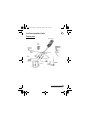 3
3
-
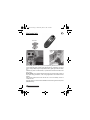 4
4
-
 5
5
-
 6
6
-
 7
7
-
 8
8
-
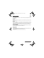 9
9
-
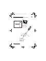 10
10
-
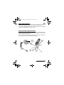 11
11
-
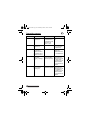 12
12
-
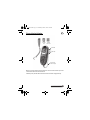 13
13
-
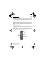 14
14
-
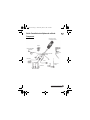 15
15
-
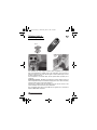 16
16
-
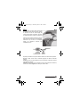 17
17
-
 18
18
-
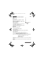 19
19
-
 20
20
-
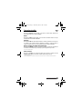 21
21
-
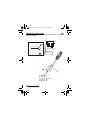 22
22
-
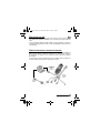 23
23
-
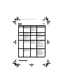 24
24
-
 25
25
-
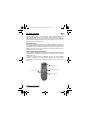 26
26
-
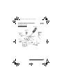 27
27
-
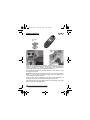 28
28
-
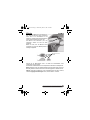 29
29
-
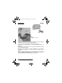 30
30
-
 31
31
-
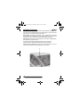 32
32
-
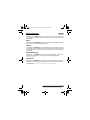 33
33
-
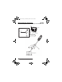 34
34
-
 35
35
-
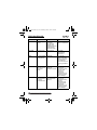 36
36
-
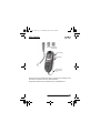 37
37
-
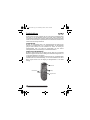 38
38
-
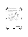 39
39
-
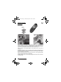 40
40
-
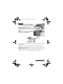 41
41
-
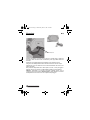 42
42
-
 43
43
-
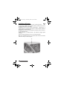 44
44
-
 45
45
-
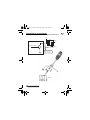 46
46
-
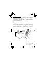 47
47
-
 48
48
-
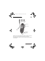 49
49
-
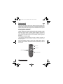 50
50
-
 51
51
-
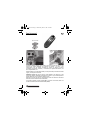 52
52
-
 53
53
-
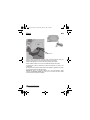 54
54
-
 55
55
-
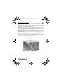 56
56
-
 57
57
-
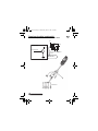 58
58
-
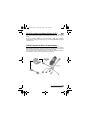 59
59
-
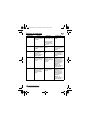 60
60
-
 61
61
-
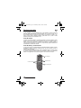 62
62
-
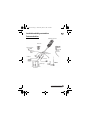 63
63
-
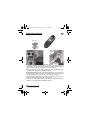 64
64
-
 65
65
-
 66
66
-
 67
67
-
 68
68
-
 69
69
-
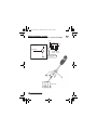 70
70
-
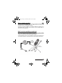 71
71
-
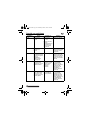 72
72
-
 73
73
-
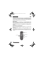 74
74
-
 75
75
-
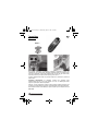 76
76
-
 77
77
-
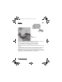 78
78
-
 79
79
-
 80
80
-
 81
81
-
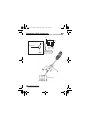 82
82
-
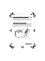 83
83
-
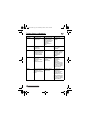 84
84
-
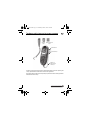 85
85
-
 86
86
-
 87
87
-
 88
88


en otros idiomas
- français: Motorola M930 Guide d'installation
- italiano: Motorola M930 Guida d'installazione
- English: Motorola M930 Installation guide
- Deutsch: Motorola M930 Installationsanleitung
- русский: Motorola M930 Инструкция по установке
- Nederlands: Motorola M930 Installatie gids
Artículos relacionados
Otros documentos
-
Acer M900 Guía de inicio rápido
-
 Metcal MFR-1300 Series Guía del usuario
-
CARLO GAVAZZI UWP-MODEM-KIT-4G-EU Guía de instalación
-
 Pei tel PTCarPhone 6 Manual de usuario
-
CARLO GAVAZZI UWP-MODEM-KIT-4G-E01 Guía de instalación
-
Dometic Frigo DC VAK (Mercedes Citan/Renault Kangoo) Guía de instalación
-
Asus M930 Manual de usuario
-
-
LG LPX-M930A El manual del propietario
-
Alpine CDA-9887 El manual del propietario

