Frigidaire AGQ7000ES0 Guía de instalación
- Categoría
- Secadoras
- Tipo
- Guía de instalación
Este manual también es adecuado para

Pre-lnstallationRequirements.................................................................2
I
I
stallati
structi
Instrucciones
Electrical Requirements ........................................................................... 2
Exhaust System Requirements .................................................... 2-3
GasSupply Requirements ........................................................................ 3
Location of Your Dryer............................................................................. 3
Rough-in Dimensions ............................................................................... 4
Mobile Home installation ......................................................................... 5
Unpacking .......................................................................................... 5
Reversing Door Swing ............................................................................. 6
Electrical installation ........................................................................ 7
Grounding Requirements ................................................................ 7
Electrical Connections--3-wire ............................................................... 7
Electrical Connections--4-wire .............................................................. 8
GasConnection ...................................................................................... 8
General installation ................................................................................. 8
Replacement Parts.................................................................................. 8
EspanOI .................................................................. 9-1 5
Requerimientos de instalaci0n preliminares ............................................. .9
Requerimientos electricos ........................................................................ 9
Requerimientos del sistema de escape............................................. 9-10
Requerimientos del suministro degas..................................................... 10
Ubicadon desu secadora....................................................................... 10
Dimensiones para la instalad0n .......................................................... 11
Instalacion en casas moviles ............................................................. 12
Desembalaje .............................................................................. 12
Puerta reversible ........................................................................ 13
Instaladon electrica ....................................................................... 14
Requerimientos para la puesta a tierra .......................................... 14
Conexiones electricas - trifilares ................................................ 14
Conexiones ebctricas - tetrafilares ............................................... 15
Conexi0n del gas ........................................................................... 15
General Instaladon ............................................................................ 15
Piezas de recambio ....................................................................... 15
Before beginning installation, carefully read these instructions. This will simpfify the installation and ensure the dryer is installed correctly
and safely. Leave these instructions near the Dryer after installation for future reference.
NOTE: The electrical service to the Dryer must conform with local codes and ordinances and the latest edition of the National Electrical Code, ANSI/NFPA
70, or in Canada, the Canadian electrical code C22.1 part 1.
NOTE: The gas service to the Dryer must conform with local codes and ordinances and the latest edition of the National Fuel Gas Code ANSi Z223.1, or
in Canada, CAN/ACG B149.1-2000
NOTE: The Dryer is designed under ANSi Z 21.5.1 or ANSI/UL 2158 - CAN/CSA C22.2 No. 112 (latest editions) for HOME USE only. This Dryer is not
recommended for commercial applications suct_ as restaurants or beauty salons, etc.
Antes de comenzar la instalacion, lea cuidadosamente estas instrucciones. Esto simplificar_ la instalacion y asegurar_ que la secadora se
instale correctamente y de manera segura. Despu_s de comp/etar /a instalacion, co/oque estas instrucciones cerca de /a secadora para
referencia futura.
NOTA: La alimentaci6n electrica para la secadora debera cumpNr con los cOdigos y reglamentos locales y con la Oldma ediciOn del C6digo Electrico National,
ANSI/NFPA 70.
NOTA: La alimentaci6n de gas para lasecadora debera cumplir con los codigos y reglamentos locales y con la uRima edition del C6digo National para Gases
Combustibles, ANSi Z223.1.
NOTA: Lasecadora esta dasificada para USO DOMESTICO solamente, de acuerdo con la norma ANSi Z 21.5.1 o ANSI/UL 2158 - CAN/CSA C22.2 (las uRimas
ediciones). Esta secadora no se recomienda para uso commercial tal como en restaurantes, salones de belleza, etc.
I__ For your safety the information in this manual must be followed to minimize the risk of fire or explosion or to prevent property damage,
personal injury or loss of life.
- Do not store or use gasoline or other flammable vapors and liquid in the vicinity of this or any other appliance.
- WHAT TO DO IF YOU SMELL GAS
• Do not try to light any appliance.
Do not touch any electrical switch; do not use any phone in your building.
Clear the room, building or area of all occupants.
Immediately call your gas supplier from a neighbor's phone. Follow the gas supplier's instructions.
If you cannot reach your gas supplier, call the fire department.
Installation and service must be performed by a qualified installer, service agency or the gas supplier.
F_ Para su seguridad, siga las instrucciones contenidas en este manual a fin de redudr a un minimo los riesgos de incendio o explosion o
para evitar daflos materiales, lesiones personales o la muerte.
No almacene ni utiNce gasolina u otros vapores y Nquidos inflamables en la proximidad de este o de cualquier otro artefacto electrico.
QUE DEBE HACER SI PERCIBE OLOR A GAS
• No trate de encender ning0n artefacto electrico.
• No toque ningun interruptor electrico; no use ningun telefono en su edificio.
• Haga salir atodos los ocupantes de la habitation, del edificio y del lugar.
• Llame a su proveedor de gas desde el telefono de un vecino. Siga las instrucciones del proveedor de gas.
• Si no Iogra comunicarse con su proveedor de gas, Ilame al departamento de bomberos.
La instaladon y el servido de mantenimiento debe de realizarlos un instalador calificado, la agencia de servidos o el proveedor de gas.
Printed in U.S.A. P/N 134732700 (0602)

PRE-INSTALLATION REQUIREMENTS
Tools and Materials Required for Installation:
1. Phillips head screwdriver.
2. Channel-lock adjustable pliers.
3. Carpenter's level.
4. Flat or straight blade screwdriver.
5. Duct tape.
6. Rigid or flexible metal 4 inch (10.2 cm) duct.
7. Vent hood.
8. Pipe thread sealer (Gas).
9. Plastic knife.
ELECTRICAL REQUIREMENTS
ELECTRIC Dryer
CIRCUIT - individual 30 amp. branch circuit fused with 30 amp. minimum
time delay fuses or circuit breaker.
POWER SUPPLY - 3 wire or 4-wire, 240 volt, single phase, 60 Hz,Alternating
Current.
POWER SUPPLY CORD KIT - The dryer MUST employ a 3-conductor power
supply cord NEMA 10-30 type SRDTrated at 240 volt AC minimum, 30 amp.,
with 3 open end spade lug connectors with upturned ends or closed loop
connectors OR a 4-conductor power supply cord NEMA 14-30 type SRDTor
ST (as required) rated at 240 volt AC minimum, 30 amp., with 4 open end
spade lug connectors with upturned ends or closed loop connectors and
marked for use with clothes dryers. If being installed in a new branch circuit
installation, manufactured (mobile) home, recreational vehicle or area which
prohibits grounding through the neutral conductor, the dryer MUST employ
a 4-conductor power supply cord NEMA 14-30 type SRDTor ST (as required)
rated at 240 volt AC minimum, 30 amp., with 4 open end spade lug connectors
with upturned ends or closed loop connectors and marked for use with
clothes dryers. See ELECTRICALCONNECTIONS for additional instructions.
CANADA - A 4 wire power cord is installed on dryer.
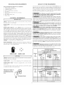
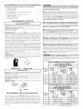
OUTLET RECEPTACLE- NEMA 10-30R (3-wire) receptacle or NEMA 14-
30R (4-wire) receptacle to be located so the power supply cord is accessible
when the dryer is in the installed position.
NEMA 10-30R NEMA 14-30R
i GAS Dryer i
CIRCUIT- Individual 15 amp. branch circuit fused with a 15 amp. maximum
time delay fuse or circuit breaker.
POWER SUPPLY - 3 wire, 120 volt single phase, 60 Hz, Alternating Current.
POWER SUPPLY CORD - The dryer is equipped with a 120 volt 3-wire
power cord.
Use separately fused circuits for washers and dryers, and DO NOT operate
a washer and a dryer on the same circuit.
NOTE: Do not under any
circumstances remove
grounding prong from
plug,
_ROUNDING PRONG
EXHAUST SYSTEM REQUIREMENTS
Use only 4 inch (10.2 cm) diameter (minimum) rigid or flexible metal duct and
approved vent hood which has a swing-out damper(s) that open when the
dryer is in operation. When the dryer stops, the dampers automatically close
to prevent drafts and the entrance of insects and rodents. To avoid restricting
the outlet, maintain a minimum of 12 inches (30.5 cm) clearance between
the vent hood and the ground or any other obstruction.
The following are specific requirements for proper
and safe operation of your dryer. Failure to follow these instructions
can create excessive drying times and fire hazards.
Do not use plastic flexible duct to exhaust the dryer.
Excessive lint can build up inside exhaust system and create a fire hazard and
restrict air flow. Restricted air flow will increase dryer times. If your present
system is made up of plastic duct or metal foil duct, replace it with a rigid or
flexible metal duct Ensure the present duct is free of any lint prior to
installing dryer duct.
If the dryer is not exhausted outdoors, some fine lint
will be expelled into the laundry area. An accumulation of lint in any area
of the home can create a health and fire hazard. The dryer exhaust
system MUST be exhausted to the outside of the dwelling!
Do not allow combustible materials (for example:
clothing, draperies/curtains, paper) to come in contact with exhaust
system. The dryer MUSTNOT be exhausted into a chimney, a wall, a ceiling,
or any concealed space of a building which can accumulate lint, resulting in
a fire hazard.
Exceeding the length of duct pipe or number of elbows
allowed in the "MAXIMUM LENGTH" charts can cause an accumulation
of lint in the exhaust system. Plugging the system could create a fire hazard,
as well as increase drying times.
Do not screen the exhaust ends of the vent system,
nor use any screws or rivets to assemble the exhaust system. Lint can
become caught in the screen, on the screws or rivets, clogging the duct work
and creating a fire hazard as well as increasing drying times. Use an approved
vent hood to terminate the duct outdoors, and seal all joints with duct tape.
All male duct pipe fittings MUST be installed downstream with the flow of
air.
Explosion hazard. Do not install the dryer where
gasoline or other flammables are kept or stored. If the dryer is installed
in a garage, it must be a minimum of 18 inches (45.7 cm) above the floor.
Failure to do so can result in death, explosion, fire or burns.
Number
of
90°
Turns
0
1
2
3
4
Number
of
90°
Turns
0
1
2
3
MAXIMUM LENGTH
of 4" (10.2 cm) Dia. Rigid Metal Duct
VENT HOOD TYPE
(Preferred)
(10.2 cm)
60 ft.
52 ft.
44 ft.
32 ft.
28 ft.
Louvered
(18.28 m)
(15.84 m)
(13.41 m)
(9.75 m)
(8.53m)
MAXIMUM LENGTH
(6.35 cm)
4sft !14_3m!
40 ft./12.19 m_
32 ft. (9.75 m)
24 ft. (7.31 m)
16 ft. (4.87 m)
of 4" (10.2 cm) Dia. Flexible Metal Duct
VENT HOOD TYPE
(Preferred)
Louvered
(10.2 cm)
30 ft. (9.14 m)
22 ft. (6.71 m)
14 ft. (4.27 m)
(6.35cm)
18 ft. (5149 m)
14ft. (4.27 m!
loft. (3.05 m!
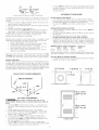
NOT RECOMMENDED
2

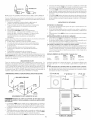
_NCORRECT
INSTALL MALE FITTINGS IN CORRECT DIRECTION
In installations where the exhaust system is not described in the charts, the
following method must be used to determine if the exhaust system is ac-
ceptable:
1. Connect an inclined or digital manometer between the dryer and the
point the exhaust connects to the dryer.
2. Set the dryer timer and temperature to air fluff (cool down) and start
the dryer.
3. Read the measurement on the manometer.
4. The system back pressure MUST NOT be higher than 0.TB inches of
water column. If the system back pressure is lessthan 0.7B inches
of water column, the system is acceptable. If the manometer reading
is higher than 0.75 inches of water column, the system is too
restrictive and the installation is unacceptable.
Although vertical orientation of the exhaust system is acceptable, certain
extenuating circumstances could affect the performance of the dryer:
, Only the rigid metal duct work should be used.
Venting vertical through a roof may expose the exhaust system
to down drafts causing an increase in vent restriction.
Running the exhaust system through an uninsulated area may
cause condensation and faster accumulation of lint.
Compression or crimping of the exhaust system will cause an
increase in vent restriction.
The exhaust system should be inspected and cleaned a minimum of every
18 months witt_ normal usage. The more the dryer is used, the more often
you should check the exhaust system and vent hood for proper operation.
EXHAUST DIRECTION
All dryers shipped from the factory are set up for rear exhausting. Howevel;
on electric dryers, exhausting can be to the right or left side of the cabinet
or the bottom of the dryer. On gas dryers, exhausting can be to the right
side of the cabinet or the bottom of the dryer. Directional exhausting can be
accomplished by installing Exhaust Kit, P/N 131456800, available through
your parts distributor. Follow the instructions supplied with the kit.
EXHAUST DUCT LOCATING DIMENSIONS
SAME AS OTHER SIDE
GAS SUPPLY REQUIREMENTS
_Replace copper connecting pipe that is not
plastic-coated. Stainless steel or plastic-coated brass MUST be
used.
1. Installation MUST conform with local codes, or in the absence of
local codes, wittq the National Fuel Gas Code, ANSI Z223.1 (latest
edition).
2. Ttqe gas supply line should be of 1/2 inch (1.27 cm) pipe.
3. If codes allow, flexible metal tubing may be used to connect your
dryer to ttqe gas supply line. The tubing MUST be constructed of
stainless steel or plastic-coated brass.
4. The gas supply line MUST have an individual shutoff valve.
5. A 1/8 inch (0.32 cm) N.P.T.plugged tapping, accessible for test
gauge connection, MUST be installed immediately upstream of ttqe
gas supply connection to the dryer.
6. Tt_e dryer MUST be disconnected from the gas supply piping
system during any pressure testing of tt_e gas supply piping system
at test pressures in excess of 1/2 psig (:3.45 kPa).
3
7. The dryer MUST be isolated from the gas supply piping system during
any pressure testing of the gas supply piping system at test pressures
equal to or less than
1/2 psig (:3.45 kPa).
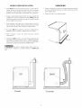
LOCATION OF YOUR DRYER
DO NOT INSTALL YOUR DRYER:
1. In an area exposed to dripping water or outside weather conditions.
2. In an area where it will come in contact with curtains, drapes, or anything
that will obstruct the flow of combustion and ventilation air.
3. On carpet. Floor MUST be solid with a maximum slope of 1 inch (2.54
cm).
INSTALLATION IN RECESS OR CLOSET
1. A dryer installed in a bedroom, bathroom, recess or closet, MUST be
exhausted outdoors.
2. No other fuel burning appliance shall be installed in the same closet as
the Gas dryer.
3. Your dryer needs the space around it for proper ventilation.
DO NOT install your dryer in a closet with a solid door.
4. A minimum of 120 square inches (774.2 square cm) of opening, equally
divided at the top and bottom of the door, is required. Air openings are
required to be unobstructed when a door is installed. A Iouvered door
with equivalent air openings for the full length of the door is acceptable.
MINIMUM INSTALLATION CLEARANCES - Inches (cm)
SIDES REAR TOP FRONT
Alcove 0 (0 cm) 0 (0 cm) 0 (0 cm)
Closet 0 (0 cm) 0 (0 cm) 0 (0 cm) 1 (2.S4 cm)
Closet door ventilation required: 2 Iouvered openings each 60 square inches
(387 square centimeters) -- 3 inches (7.6 cm) from bottom and top of door.
This dryer MUST be exhausted outdoors.
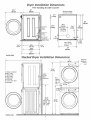
5. The following illustrations show minimum clearance dimensions for proper
operation in a recess or closet installation.
IB
(ocm)
II
0" (0 cm)
u
1" (2. 54 cm) _ii'_ 0" (0 cm)
iI F
iii
_ ill
....... iii
CLOSET DOOR

23¾"
(60.33)
25/8"
(6.67)
inches (cm)
Dryer Installation Dimensions
Free-Standing & Under Counter
5,875"(14.93)
To base
exhaust
4,375"(11.12)
To side
exhausts
To front of cabinet
28.25"(71.76)
To clear kobs
28.75"(73.03)
To clear door
29.5"(74.93)
To clear open door
53"(134.62)
\
29¾"
175.57)
5.0"(12.7) 5 t_
Center line
, height f....... (12.70)
I right, left vent -- _--
t__15/8"
(4.13)
4
223/4''
(57.79)
24318"
(61,91)
27"
(68.58)
Electrical supply
on rear of unit
J
/
13½"
(34.29) 23/8"
To rear (6.0 t
and base
exhausts
.©
_
Gas s_y
pipe on rear
of unit
27 _
(68.58)
Stacked Dryer instaflation Dimensions
I
41.00"
(97.16)
Center line
i height for
i rear, right,
; left vents
inches (cm)
T
72.00"
(172.88)
Gas
supply
pipe on
rear of
unit
2.375"
(6.03)
38.25"
(97.16)
27"
(68.58)
(34.29) _
--l--l-- --
/
\
A
34,_
86._6)
2.25"
(5.72)
t r _ .......... ,
4
35 _
[88.9o)
Electrica!
supply on
rear of
_ unit

MOBILE HOME INSTALLATION
1. Dryer MUST be exhausted outside (outdoors, not beneath the
mobile home) using metal ducting that will not support
combustion. Metal ducting must be 4 inches (10.16 cm) in
diameter with no obstructions. Rigid metal duct is preferred.
2. If dryer is exhausted through the floor and area beneath the
mobile home is enclosed, the exhaust system MUST terminate
outside the enclosure with the termination securely fastened
to the mobile home structure.
3. When installing a gas dryer into a mobile home, a provision
must be made for outside make up air. This provision is to be
not less than twice the area of the dryer exhaust outlet.
4. This dryer MUST be fastened to the floor. Mobile Home
Installation Kit No. 346764 is available from your dealer.
5. Refer to pages 2 and 3 for other important venting
requirements.
6. Installation MUST conform to current Manufactured Home
Construction & Safety Standard (which is a Federal Regulation
Title 24 CFR-Part 32-80) or when such standard is not applicable,
with American National Standard for Mobile Homes.
The dryer is designed under ANSI Z 21.5.1 or
ANSI/UL2158 - CAN/CSA C22.2 (latest editions) for HOME USE
only.
UNPACKING
1. Using a rug, blanket or a piece of cardboard packing to protect
the floor, carefully lay the dryer on its left side and remove the
foam shipping base.
2. Return the dryer to an upright position.
FOAM
SHIPPING
_ING
: ¸¸¸DO
ii i
DON'T
Correct
Incorrect

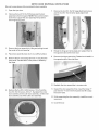
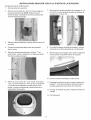
DRYER DOOR REVERSAL INSTRUCTIONS
Be sure to wear gloves while reversing the door assembly,
,
2.
,
,
5.
Open the dryer door.
Remove the two #10-16x.50 that secures the door
assembly to the front panel. NOTE: Remove the bottom
screw first. Support the door assembly firmly before
removing the top screw.
Remove the door assembly by lifting and pulling toward
the center of the unit opening.
Place door assembly face down on a soft flat surface.
Remove the two round plugs and one "T" plug from the
front panel. Reinstall them in the position vacated by
the hinge.
Remove the two #10-16x.50 hinge attachment screws
and the two #10-16x.50 striker plate attachment
screws.
Rotate the hinge and strike plate and reattach them to
the opposite sides of the inner door.
Remove the hinge cutout plug. Rotate it and install it in
the opposite side of the outer door.
,
Remove the five #10-14x5/8 screws, 1 thru 5 and the
two #10-16x.50 screws, 6 thru 7, that attach the inner
door assembly to the outer door assembly. Lift the inner
door assembly out of the outer door assembly.
10. Reattach the door assemblies in reverse order.
11. Support the door assembly firmly; insert the hinge "T"
post into the "T" slot in the front panel and lift to align
the screw holes.
12. While supporting the door assembly, install the mount-
ing screws.
13. Close the door.

ELECTRICAL INSTALLATION
1 ELECTRICDryer I[
The following are specific requirements for proper and
safe electrical installation of your dryer. Failure to follow these
instructions can create electrical shock and/or a fire hazard.
This appliance MUST be properly grounded. Electrical
shock can result if the dryer is not properly grounded. Follow the instructions
in this manual for proper grounding.
Do not use an extension cord with this dryer. Some
extension cords are not designed to withstand the amounts of electrical
current this dryer utilizes and can melt, creating electrical shock and/or fire
hazard. Locate the dryer within reach of the receptacle for the length
power cord to be purchased, allowing some slack in the cord. Refer to the
pre-insta%tion requirements in this manual for the proper power cord to be
purchased.
A U.L. approved strain relief must be installed on to power
cord. If the strain relief is not attached, the cord can be pulled out of the
dryer and can be cut by any movement of the cord, resulting in electrical
shock.
Do not use an aluminum wired receptacle with a copper
wired power cord and plug (or vice versa). A chemical reaction occurs
between copper and aluminum and can cause electrical shorts. The proper
wiring and receptacle is a copper wired power cord with a copper
wired receptacle.
NOTE: Dryers operating on 208 volt power supply will have longer
drying times than operating on 240 volt power supply.
GROUNDING REQUIREMENTS
NON-CANADIAN ELECTR/C Dr er
Improper connection of the equipment grounding conductor
can result in a risk of ebctrical shock. Check with a licensed electrician if you
are in doubt as to whether the appliance is properly grounded.
For a grounded, cord-connected dryer:
1. The dryer MUST be grounded. In the event of a malfunction or
breakdown, grounding will reduce the risk of electrical shock by a path
of least resistance for electrical current.
2. If your dryer is equipped with a power supply cord having an equipment-
grounding conductor and a grounding plug, the plug MUST be plugged
into an appropriate, copper wired receptacle that is properly installed
and grounded in accordance with all local codes and ordinances. If in
doubt, call a licensed electrician. Do not modify plug provided with
the appfiance.
For a permanently connected dryer:
1. The dryer MUST be connected to a grounded metal, permanent wiring
system; or an equipment grounding conductor must be run with the
circuit conductors and connected to the equipment-grounding terminal
or lead on the appliance.
Canadian ELECTRIC Dryer
jj_r_jj_ improper connection of the equipment grounding conductor
can result in a risk of electrical shock. Check with a licensed electrician if you
are in doubt as to whether the appliance is properly grounded.
For a grounded, cord-connected dryer:
1. The dryer must be grounded. In the event of a malfunction or breakdown,
grounding will reduce the risk of electrical shock by a path of least
resistance for electrical current.
2. Since your dryer is equipped with a power supply cord having an
equipment-grounding conductor and a grounding plug, the plug must
be plugged into an appropriate outlet that is properly installed and
grounded in accordance with all local codes and ordinances, if in doubt,
call a licensed electrician. Do not modify plug provided with the
appliance.
ALL GASDryers
This dryer isequipped with athree-prong (grounding) plug for your protection
against shock hazard and should be plugged directly into a properly grounded
three-prong receptacle. Do not cut or remove the grounding prong from this
plug.
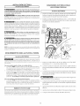
ELECTRICAL CONNECTIONSFOR 3-WIRE SYSTEM
NON-CANADIAN ELECTRIC Dryer ]
1. Remove the screws securing the terminal block access cover and the
strain relief mounting bracket located on the back of the dryer upper
corner.
2.
3.
4.
5.
Install a U.L. approved strain relief into the power cord entry hole of the
mounting bracket. Finger tighten the nut only at this time.
Thread a U.L approved 30 amp. power cord, NEMA 10-30 type SRDT,
through the strain relief.
Attach the power cord neutral (center wire) conductor to the silver
colored center terminal on the terminal block. Tighten the screw securely.
Attach the remaining two power cord outer conductors to the outer
brass colored terminals on the terminal block. Tighten both screws
securely.
Do not make a sharp bend or crimp wiring/conductor
at connections.
Reattach the strain relief mounting bracket to the back of the dryer
with two screws. Tighten screws securely.
GREEN
SCREW
NEUTRAL
GROUND
WIRE
SILVER
TERMINAL
NUT
TO THESE
4READS
BRACKET POWER CORD
7. Tighten the screws securing the cord restraint firmly against the power
cord.
8. Tighten the strain relief nut securely so the strain relief does not turn.
9. Reinstall the terminal block cover.

ELECTRICAL CONNECTIONS FOR 4-WIRE SYSTEM
NON-CANAD/AN ELECTR/C Dryer
1. Remove the screws securing the terminal block access cover and
the strain relief mounting bracket located on the back of the dryer
upper corner.
2. Install a U.L. approved strain relief in the entry hole of the mounting
bracket. Finger tighten the nut only at this time.
3. Remove the ground wire from the green ground screw located
above the terminal block.
GREEN POWER CORD
GREEN WIRE
SILVERTERMINAL
SCREW / TERMINAL
p ::_BLO¢IK
/"_ BLA¢IK TIGHTEN
NUT
GROUND WHITE TO THESE
WIRE
NUT _HREADS
STRAIN /
RELIEF ",J'_ / /
MOUNT1NG_ X //J"_"
BRAC E\I'--
POWER z,_. "_.
CORD [i-P \ "
Thread a U.L approved 30 amp power cord, NEMA 14-30 type ST or
SRDTthrough the strain relief.
TYPI¢IAL 4 _(I/_I ¢_WHITE
CONDUCTOR _.. 'II Y TYPICAL 4 BLACK
_t_ED
30 AMP NEMA 14-30 TYPE SRDT OR ST _4_GREEN
Attach the green power cord ground wire to the cabinet with the
green ground screw.
Attach the white (neutral) power cord conductor from the power
cord and the neutral ground wire from the dryer harness to the
silver-colored center terminal on the terminal block. Tighten the
screw securely.
Attach the red and black power cord conductors to the outer
brass-colored terminals on the terminal block.
Do not make a sharp bend or crimp wirin_conductor
at the connections.
8. Tighten the screws securing the cord restraint firmly against the
power cord.
9. Tighten the strain relief nut securely so the strain relief does not
turn.
10. Reinstall the terminal block access cover.
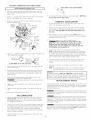
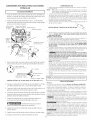
GAS CONNECTION
Remove the shipping cap from gas pipe at the rear of the dryer.
NOTE; DO NOT connect the dryer to L.R gas service without
converting the gas valve. An L.R conversion kit must be installed
by a qualified gas technician.
Connect a 1/2 inch (1.27 cm) I.D. semi-rigid or approved pipe from
gas supply line to the 3/8 inch (0.96 cm) pipe located on the back
of the dryer (see pages 6 and 7). Use a 1/2 inch to 3/8 inch (1.27
cm to 0.96 cm) reducer for a connection. Apply an approved
thread sealer that is resistant to the corrosive action of liquefied
gases on all pipe connections.
VALVE OPEN / GAS FLOW POSITION
4. Test all connections by brushing on a soapy water solution. NEVER test
for gas leaks with an open flame.
GENERAL INSTALLATION
1. Connect the exhaust duct to outside exhaust system {see pages 3
and 4). Use duct tape to seal all joints.
With the dryer in its final position, adjust one or more of the legs
until the dryer is resting solid on all four legs. Place a level on top
of the dryer. The dryer MUST be level and resting sofid on all
four legs.
3. Plug the power cord into a grounded outlet. NOTE: Check to
ensure the power is off at circuit breaker/fuse box before plugging
the power cord into the outlet.
Turn on the power at the circuit breaker/fuse box.
Before operating the dryer, make sure the
dryer area is clear and free from combustible materials,
gasoline, and other flammable vapors. Also see that
nothing (such as boxes, clothing, etc.) obstructs the flow
of combustion and ventilation air.
Run the dryer through a cycle check for proper operation.
NOTE: On gas dryers, before the burner will light, it is necessary
for the gas line to be bled of air. If the burner does not light within
45 seconds the first time the dryer is turned on, the safety switch
will shut the burner off. If this happens, turn the timer to "OFF" and
wait 5 minutes before making another attempt to light.
6. If your dryer does not operate, please review the "Avoid Service
Checklist" located in your Use and Care Guide before calling for
service.
Place these instructions in a location near the dryer for future
reference.
NOTE: A wiring diagram/tech sheet is in an envelope attached to
the inside side panel of the dryer by the blower housing.
Pedestal
A pedestal accessory, Model No. APWD15W, specifically designed
for this dryer may be used when elevating the dryer for ease of use.
Failure to use accessories certified by the manufacturer could result
in personal injury, property damage or damage to the dryer.
REPLA CEMENT PARTS
If replacements parts are needed for your dryer, contact the source
where you purchased your dryer, call 1-800-944-9044, or visit our website,
www.frigidaire.com, for the Frigidaire Company Authorized Parts
Distributor nearest you.
Label all wires prior to disconnection when servicing controls.
Wiring errors can cause improper and dangerous operation. Verify proper
operation after servicing.
Destroy the carton and plastic bags after the dryer is
unpacked. Children might use them for play. Cartons covered with rugs,
bedspreads, or plastic sheets can become airtight chambers causing
suffocation. Place all materials in a garbage container or make materials
inaccessible to children.
The instructions in this manual and all other literature included
with this dryer are not meant to cover every possible condition and situation
that may occur. Good safe practice and caution MUST be applied when
installing, operating and maintaining any appliance.
3. Open the shutoff valve in the gassupply line to allow gas to flow
through the pipe.
8

REQUERIMIENTOS DE INSTALA CION PRELIMINARES
Herramientas y materiales necesarios para la instalacion:
1. Destornillador Phillips
2. Alicates universales
3. Nivel de carpintero
4. Destornillador para tornillo de cabeza plana o recta
5. Cinta para ductos
6. Ducto metalico rigido o flexible de 4"(10,2 cm)
7. Caperuza de salida
8. Sellador de tuberias (gas)
9. Un cuchillo de plastico
REQUERIMIENTOS ELECTRICOS
1 SecadorasELECTRICAS ]
CIRCUITO- Circuito derivado individual de 30amperios, con fusibles de 30 amp.
del tipo de retardo minimo o disyuntores.
ALIMENTACION ELECTRICA - Corriente alterna, monofasica, 60 Hz, 240
voltios; trifilar o tetrafilar.
CORDON ELECTRICO - En la secadora se DEBE usar un cord6n electrico trifilar
NEMA 10-30 tipo SRDTpara un voltaje nominal minimo de 240 voltios CA, 30
amp., con 3 conectores de horquillas con terminales abiertos y extremes
dirigidos hacia arriba o conectores de anillo cerrado y marcados para use en
secadoras de ropa o un cordOn electrico tetrafilar NEMA 14-30 tipo 5RDT o ST
(come sea necesario) para un voltaje nominal minimo de 240 voltios CA, 30
amp. con 4 conectores de horquillas con terminales abiertos yextremos dirigidos
hacia arriba o conectores de anillo cerrado.
Sisiendo instalado en una nueva instalaciOn del circuito del rama, un vehiculo
casero, recreational (m6vil) manufacturado o un area que prohiben el poner
a tierra a traves del conductor neutral, se DEBE utilizar un cordon electrico
tetrafilar NEMA 14-30 tipo SRDTo ST (come sea necesario) para un voltaje
nominal minimo de 240 voltios CA, 30 amp. con 4conectores de horquillas con
terminales abiertos y extremes dirigidos hacia arriba o conectores de anillo
cerrado y marcados para use en secadoras de ropa. Ver CONEXIONES
ELECTRICASpara adicional informaci6n.
(Canada - un cord6n de suministro de energia de 4 alambres es instalado en
la secadora.)
TOMACORRIENTE - El tomacorriente NEMA 10-30R (3 alambres) o NEMA
14-30R (4 alambres) debe estar ubicado de manera que el cord6n electrico
Ilegue hasta el cuando la secadora este instalada.
W!_ Los siguientes requerimientos son especificos para el
funcionamiento correcto y seguro de su secadora. El incumplimiento
de estas instrucciones puede causar prolongation excesiva del tiempo
de secado y riesgos de incendio.
[] No use ductos flexibles de pl_stico para el escape de la secadora.
Se puede acumular un exceso de pelusas en el sistema de escape, crear un
riesgo y obstruir el flujo de aire. La restricci6n del flujo del aire prolongara el
tiempo de secado. Sisu sistema de escape actual tiene ductos de plastico o de
laminas metalicas delgadas, reempl_celo con un ducto metalico rigido o
flexible. Asegurese de que los ductos existentes no tengan pelusas
antes de instalar el ducto de la secadora.
[]Si el escape de la secadora no se dirige al exterior, algunas pelusas
finas ser&n sopladas hacia el recinto donde se efectOa el lavado. La
acumulaciOn de pelusas en cualquier lugar de la casa, puede treat un peligro
para lasalud y un riesgo de incendio, iEIsistema de escape de la secadora
DEBE estar dirigido hacia el exterior de la vivienda!
[] No permita que los materiales combustibles (per ejemplo: la ropa,
cortinas/cortinajes, papel) tengan contacto con los ductos. El escape
de lasecadora NO DEBE dirigirse hacia el interior de una chimenea, hacia una
pared, hacia el cielo raso o hacia cualquier otro espacio reducido del edificio,
donde puede ocurrir acumulacion depelusas yconstituir un peligro de incendio.
[] Exceder la Iongitud del conducto rigido, o los numeros de codes
permitidos en los diagramas "LARGO MAXIMO" puede disminuir la
capacidad de exhaustaci6n del sistema. Obstruir el conducto puede provocar
peligro de incendio, asl come aumentar el tiempo de secado.
[] No coloque un filtro en el extreme del escape del sistema ni emplee
tornillos o remaches para ensamblar el sistema de escape. Las pelusas
podrian quedar atrapadas en los filtros, en los tornillos o en los remaches, Io
cual obstruida el sistema de escape y crearia un riesgo de incendio, asi come
tambien prolongaria eltiempo desecado. Useuna caperuza de salida adecuada
para el extreme del ducto que salga al exterior de la vivienda y selle todas las
juntas con cinta adhesiva para ductos. Todos los accesorios de tuberia machos,
DEBEN ser instalados aguas abajo del flujo de aire.
F_ Riesgo de explosion. No instale la secadora donde se
guarda gasolina u otros materiales inflamables. Si la secadora se instala
en un garage, ella debe estar per Io menos 18 pulgadas (45,7 cm) per encima
del suelo. El incumplimiento puede resultar en la muerte, explosiOn, incendio,
o quemaduras.
LARGO MAXIMO del Conducto Met_lico Rigido
de 4" (10,2 cm) de Di_metro
TIPO DE CAPERUZA DE SALIDA
(Preferido)
NEMA 10-30R NEMA 14-30R N_mero
[ S odo o oGAS i deaCodo 90o
I i
CIRCUITO - Circuito individual derivado de 15 amp, con fusibles de 15 amp. de _ 4z"
retardo maximo o disyuntor. (10,2 cm)
Utilice circuitos de fusibles separados para la lavadora y la secadora, No opere 0 60 pies
una lavadora y una secadora en el mismo circuito.
1 52 pies
ALIMENTACION ELECTRICA - Corriente alterna, monofasica, 60 Hz, 120
voltios, trifilar. 2 44 pies
CORDON ELECTRICO - La secadora esta equipada con un cordOn electrico 3 32 pies
trifilar para 120 voltios. 4 28 pies
ESPIGA
REQUERIMIENTOS DEL SISTEMA DE ESCAPE
Utilice solamente ductos met&licos, rigidos o flexibles de 4"
(19,2 cm) de diametro (minimo) yuna caperuza de salida de use aprobado, con
registros que giren hacia afuera que se abren cuando la secadora se encuentra
en funcionamiento. Cuando la secadora se detiene, los registros se cierran
automaticamente para evitar las corrientes de aire y la entrada de insectos y
roedores. Para evitar obstruir la salida, mantenga una altura libre minima de
12"(30,5 cm) entre la caperuza de salida y el piso o entre cualquier otra
obstrucci6n.
Apersianada
(18,28 m)
(15,84 m)
(13,41 m)
(9,75 m)
(8,53m)
(6.38 cm)
48 pies(14,63 m)
40 pies(12,19 m)
32 pies (9,75 m)
24 pies (7,31 m)
16 pies (4,87 m)
LARGO MAXIMO del Conducto Met&lico Flexible
de 4" (10,2 crn) de Di_metro
TIPO DE CAPERUZA DE SALIDA
(Preferido)
N_Jmero _ Apersianada _1_
(10,2 cm) (6.35 cm)
0 30 pies (9,14 m) 18 pies (5,49 m)
1 22 pies (6J1 m) 14 pies (4,27 m)
2 14 pies (4,27 m) 10 pies (3,05 m)
3 NO RECOMENDADO
9 Impreso en los EE.UU.

INSTALELOSACCESORIOSMACHOSENLADIRECCIONCORRECTA
Paralasinstalacionescuyassistemadeexhaustacionnoseencuentreenel
diagrama,sepuedeutilizarelmetodoacontinuaci0nparadeterminarsielsistema
deexhaustaci0nesapropiado.
1. Conecteunmanometroatuboinclinadoodigitalentrela
secadorayeluniondeexhaustadondelasecadora.
2. Pongaelcontadordetiempodelasecadoraylatemperatura
aairefrio(enfiriamiento),ylasecadoraenlapositionde
marcha.
3. Lealamedidaindicadaenelmanometro.
4. LabajapresionNO DEBE exceder 0.75 pulgada de la
columna de agua. Si la baja presion esinferior a 0.75" de la
columna de agua, el sistema es aceptable. Si la lectura indica
una presion superior a 0.75" de lacolumna de agua, la
capaddad del circuito es insufidente y la instalad0n es
inaceptable.
Aungue un sistema vertical sea aceptable, algunas circunstancias atenuantes
pueden afectar el funcionamiento de la secadora:
o Se debe utiNzar solamente conductos metalicos rigidos.
Una salida del sistema vertical en el techo, puede exponede a
un corriente de aire descendente y disminuir asi su capaddad
de exhaustadon.
El aislante que debe atravesar el sistema puede causar
condensacion y disminuir asi la capacidad de exhaustacion
del sistema.
La capacidad de exhaustadon de un sistema de
exhaustacion comprimido o ondulado puede disminuirse.
Elsistema de exhaustacion debe de ser inspecdonado y limpiado por Io menos
carla 18 meses de uso normal. Cuanto mas la secadora esta utilizada, mas
debe verificar el buen fundonamiento del sistema de exhaustacion y de latapa
del orificio de ventilacion.
UBICAC!ON DEL ESCAPE
Todas las secadoras vienen de fabrica equipadas con escape trasero. Sin
embargo, en las secadoras electricas, el escape puede hacerse al lado derecho
o izquierdo del gabinete o en la parte inferior de la secadora. Enlas secadoras
a gas, el escape del aire puede estar en el lado derecho del gabinete o en la
parte inferior de lasecadora. Elescape direccional puede efectuarse instalando
un Juego de Escape, P/N 131456800, disponible atraves de su distribuidor de
repuestos. 5iga las instrucciones que se suministran con el juego.
DIMENSIONES PARA LA UBICACION DEL DUCTO DE ESCAPE
4 3/8 =
(11cm)
3314"
{9,5 cm) 3 3/4"
(9,5 cm)
REQUERIMIENTOS DEL SUMINISTRO DE GAS
rf'_ Reemplace la tuberia de conexibn de cobre que no est_
recubrida con pl_stico. El la tbn inoxidable o recubrido con pl_stico DEBE
SER utilizado.
1. La instalacion DEBE hacerse cumplir con los c6digos locales o en ausencia
de los mismos, de acuerdo con los estandares del National Fuel Gas Code
(Codigo Nacional para Gases Combustibles), ANSI Z223.1 (la ultima edition).
2. Latuberia de alimentaci0n de gas debe ser de 1/2 pulgada (1,27 cm) de
diametro.
3. Siesta permitido por los codigos locales, se puede usar tuberia de metal
para conectar su secadora a la Ilnea de suministro de gas. Latuberia DEBE
ser fabricada de acero inoxidable o cobre recubierto de plastico.
4. Latubeda de alimentaci0n de gas DEBE tener una Ilave de cierre individual.
5. Una toma de 1/8 de pulgada (0,32 cm) N.RT.accesible para conexi6n del
manometro de prueba, DEBE ser instalada inmediatamente aguas arriba
de la conexion de la tubeda de alimentaci6n de gas a la secadora.
6. Lasecadora DEBE serdesconectada del sistema detuberias de alimentaci6n
de gas durante cualquier ensayo de presion del sistema de tuberias de
allmentacion de gas realizado a presiones de prueba de mas de 1/2 Ibs/pulg. 2
(3,45 kPa).
7. Lasecadora DEBE aislarse del sistema de tubedas de dimentaci6n de gas
durante cualquier ensayo depresion del sistema detubedas dealimentaciOn
de gas realizado en ensayos de presion iguales o inferiores a 1/2 Ibs/pulg. 2
(3,45 kPa).
UBICACION DE SU SECADORA
NO INSTALE SU SECADORA:
1. En un lugar donde puede haber goteos de agua o quede expuesta alas
indemencias del tiempo.
2. En un area donde pueda entrar en contacto con cortinas, cortinajes o
cualquier otra cosa que obstruya el fhjo de combustion y ventilacion de
aire.
3. Sobrealfombras. ElpisoDEBEserfirmecon undesnivel maximode 1pulgada
(2,54 cm).
INSTALACiON DENTRO DE UN NICHO 0 ARMARIO
1. Silasecadora esinstalada en undormitorio, cuarto de bar,o, nicho o armario,
el tubo del escape DEBE ser instalado hacia el exterior.
2. No se debe instalar ningun otro artefacto que queme combustible en el
mismo armario en que est,1instalada la secadora a Gas.
3. Lasecadora necesita espacio a su alrededor para una ventilation adecuada.
NO instale la secadora en un armario con puerta maciza.
4. Se requiere como minimo una abertura de 120 pulgadas cuadradas (774,2
2
cm ), dividida equitativamente para la parte superior einferior de la puerta.
Cuando se instala una puerta, es necesario proveer aberturas para el aire.
Una puerta apersianada con aberturas para el aire en todo el largo de la
puerta es aceptable.
DESPEJESMiNIMOS DE INSTALACION - Pulgadas (cm)
Parte Parte Parte
Lados Trasera Superior Delantera
Alcoba 0 (0 cm) 0 (0 cm) 0 (0 cm)
Armario 0 (0 cm) 0 (0 cm) 0 (0 cm) 1 (2,54 cm)
Ventilacion requirida en la puerta del armario: dos aberturas rejilladas cada
60 pulg. 2(387 cm2) -- 3" (7,6 cm) desde la parte inferior y superior de la
puetra.
El tubo del escape de la secadora debe ser instalado hacia el exterior.
5. Las siguientes ilustraciOnes muestran las dimensiOnes minimas de espacio
libre que debe existir para el buen funcionamiento de la secadora cuando
se instala en un nicho o en un armario.
II ,, ,,
--_ii_--0 (O cm) 1" (2.54 cm) _ii_ O" (O cm)
" 0" (0 cm)
PUERTA DEL ARMARIO
10

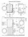
Dimensiones De la Instalac_)n
2518"
(s.s7)
"1I"
inches (cm)
223/, ''
(57.79)
24318"
(61.91)
27"
(68.58)
5.875"(14.93)
Para basar los
//extractores
Paraechar a
_un lado
5.0"(12,7)
Linea altura
, de centro para __
I el respiradero
osterior,
de[echo,
izquierdo
15/8"
(4.13)
29¾"
175.57)
5 _
(12.7o)
Fuente electrica en la parte
posterior de la unidad
/
/
o/
13½"
(34.29)
A los
e×tractores
de la parte
posterior y
de la base@
23/8_
(6.03)
34'i
(86.:6)
/ l 2.25"
_- - _ue£degas 15.72)
Pipe de la
en la parte posterior de
la unidad
=1
27"
(68.58)
Dimensiones Apiladas De la instalac_n Dei Secadora
27"
(68.58)
I
4.375"
(11.12)
Para echar
a un lado
-=xtractores
72.00"
(172,88)
fu
Pipe de la
_=nte de gas
i!n la parte
p _sterior de
la unidad \
4!.00"
(97.16)
Linea
altura de
centro para el
respiradero
posterior,
derecho,
izquierdo
11
2.375"1
(6.03)
38.25"
(97.16)
AI frente del gabinete
28.25"(7! .76)
Alas perillas claras
28.75"(73.03)
Alas perillas puerta
29.5"(74.93)
_=n ei claro abra la puerta
53"(134.62)
•, (34.29) _, _
; !:: - " _r 7
i ! ! [ _ =
/
\
inches (cm)
35 _
'88.90)
Fuente
ei6ctrica
en la
_o parte
stedor
de la
unidad

INSTALA CION EN CASAS MOVILES
1. El tubo de escape de la secadora DEBEser instalado hacia el exterior
(El escape debe colocarse en la parte exterior y no debajo de la casa
movil.) Debe usarse ducto de metal que no sea combustible. Elducto
de metal debe tenet cuatro pulgadas (10,16 cm) de di_metro y no
tener obstrucciones. Espreferible usar ducto de metal que sea rigido.
2. Si el tubo de escape de la secadora corre a traves del piso y el area
debajo de la casa mOvil es cerrada, el ducto de escape DEBEterminar
fuera del recinto, con el extremo final asegurado en contra de la
estructura de la casa mOvil.
3. AI instalar una secadora de gas en una casa movil, hay que instalar
una provision de aire fresco suplementario. La provision tiene que
ser mas grande que dos veces el espacio del escape de la secadora.
4. Esta secadora DEBE asegurarse al piso. Eljuego para instalacion en
la casa movil es el No. 346764 y Io puede adquirir con su distribuidor.
5. Vea las paginas 2 y3 para otros requisitos importantes de ventilacion.
6. La instalacion DEBE cumplir con las estandares aplicables de la
Manufactured Home Construction & Safety Standard - Estandares
de Seguridad y Construccion de Casas Prefabricadas (Titulo 24 CFR
- Parte 32-80 del Reglamento Federal) o cuando dichos estandares
no sean aplicables, se deben complir con los estandares de la American
National Standard for Mobile Homes (Estandares Nacionales
Americanas para Viviendas M0viles).
Esta secadora ha sido diser_ada PARA USO
DOMESTICO solamente, de acuerdo con la norma ANSI Z 21.5.1 o ANSI/
UL 2158-CAN/CSA C22.2 (las 01timas ediciOnes).
MODEL OS A UTONOMOS CON CONSOLA
SUPERIOR
DIMENS!ONES PARA LA INSTALACION
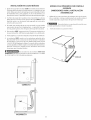
DESEMBALAJE
1. Utilizando las cuatro esquineras de embarque de la caja de carton
(dos a cada lado), coloque cuidadosamente la secadora sobre el
costado izquierdo y saque la base de espuma de embarque.
Para evitar danos, no use el panel de control como
un medio para levantar o mover la secadora.
2. Vuelva la secadora a su posici0n vertical.
PLACA DE
ESPUMA DE
_, EMBARQUE
MPAQUE
SI
©
CORRECTO
: NO_
i i iiiiii
©
INCORRECTO
12

INSTRUCCiONES PARA DAR VUELTA LA PUERTA DE LA SECADORA
Use guantes para dar vuelta la puerta.
1. Abre la puerta de la secadora.
,
Retire los dos tomillos No. 10 de 16x.50 que aseguran
la puerta al panel frontal, NOTA: Retire primero el
tomillo de abajo. Sostenga firmemente la puerta antes
de retirar el tomillo de arriba.
Retire los dos tornillos de fijaci6n de la bisagra No. 10
de 16x.50 y los dos tornillos de ajuste de la placa de
encastre No. 10 de 16x.50.
,
4.
5.
Retire la puerta levantandola y tirando hacia el centro de
la unidad.
Coloque la puerta hacia abajo sobre una superficie
plana y suave.
Retire los dos tapones redondos y un tap6n "T" del
panel frontal. Vuelva a instalarlos en el lugar que qued6
libre donde estaba la bisagra.
De vuelta la bisagra y la placa de encastre y vuelva a
colocarlas en los lados opuestos de la contrapuerta.
Retire el tap6n de la bisagra. Delo vuelta e instalelo en
el lado opuesto de la parte exterior de la puerta.
,
Retire los cinco tornillos No. 10 de 14x5/8, los tornillos
1 a 5 y los dos tornillos No. 10 de 16x.50, los tornillos 6
a 7que fijan la contrapuerta a la parte exterior de la
puerta. Levante la contrapuerta y saquela fuera de la
parte exterior de la puerta.
10.
11.
12.
Vuelva a colocar las puertas en orden inverso.
Sostenga firmemente la puerta; inserte el poste de la
bisagra "T" en la ranura Iocada en del panel frontal y
levantela para alinear los orificios de los tornillos.
Sin dejar de sostener la puerta, instale los tomillos de
montaje.
13. Cierre la puerta.
13

INS TALA C!ON ELECTRICA
Secadoras EZECTRICAS
rv._ Los siguientes requerimientos son especificos para
el funcionamiento correcto y seguro de su secadora. El incumplimien to
de estas instrucciones puede causar prolongation excesiva del tiempo
de secado y riesgos de incendio.
rv._ Este artefacto DEBE ser puesto a tierra de manera
correcta. Si lasecadora no esta debidamente puesta atierra se puede producir
un cheque electrico. 5iga las instrucciones indicadas en este manual para la
puesta a tierra en forma correcta.
F__ No use un cordon de extension con esta secadora.
Algunos cordones de extension no pueden soportar la cantidad de corriente
electrica que utiliza esta secadora y pueden fundirse, creando un peNgro de
cheque electrico y/o incendio. Ubique la secadora de manera que el cordon
electrico Ilegue hasta el tomacorriente que se va a usar, dejando un poco de
holgura para elcordon. Consuke losrequerimientos de instalaci0n preliminares
indicados en este manual para el cordon electrico que debe ser adquirido.
Se debe instalar un anclaje aprebado per el U.L.
para el cordon el_ctrice. Si no se utiliza un andaje para sujetar el cordon
electrico, este puede salirse de la secadora y cortarse con cualquier
movimiento, resukando en un cheque electrico.
No utifice un temacerriente con cables de aluminio
con un cord6n y un enchufe de cebre (e viceversa). Se produce una
reaction quimica entre el cobre y el aluminio que puede causar cortacircuitos.
El cableado y tomacorriente apropiado es un cordon el_ctrico equipado
con conductores de cobre con un tomacorriente con conductores de
cobre.
NOTA: Lassecadoras que operan con un suministro de energia de 208 voltios
usar_in mas tiempo de secado que aquellas que operan con un suministro de
energia de 240 voltios.
REQUERIMIENTOS PARA LA PUESTA A TIERRA
i SecadorasELf-CTRICAS i
La conexiOn indebida del conductor de puesta a tierra del
equipo puede ocasionar un riesgo de cheque electrico. Consulte con un
electricista profesional sitiene alguna duda respecto ala puesta atierra correcta
del artefacto.
Para una secadera puesta a tierra, con cordon el_ctrice:
1. La secadora DEBE set puesta a tierra. En case de malfuncionamiento o
falla, la puesta atierra reducira el riesgo de cheque electrico proporcionando
un trayecto de menor resistencia a la corriente electrica.
2. Si su secadora esta equipada con un cordon electrico que posee un
conductor de puesta a tierra del equipo y un enchufe de puesta a tierra,
dicho enchufe DEBE ser conectado a un tomacorriente adecuado,
debidamente instalado y puesto a tierra de acuerdo con todos los c0digos
y reglamentos locales. Si tiene alguna duda consulte a un electricista
profesional. No medifique el enchufe preperdenade la aplicadon.
Para una secadora conectada permanentemente:
1. La secadora DEBE ser conectada a un sistema de cableado metalico
permanente, puesto a tierra; o se debe instalar un conductor de puesta
a tierra de equipo junto con los conductores del circuito y conectarse al
borne de puesta a tierra del equipo o al cable del artefacto.
i TODAS/assecadorasa GAS i
Esta secadora esta equipada con un enchufe de tres espigas (de puesta a
tierra) para protecci0n en contra de cheques electricos ydebe ser conectada
directamenta en un receptaculo para tres espigas el cual debe estar puesto
a tierra. No corte ni elimine la espiga de puesta a tierra de este enchufe.
CONEXIONES ELE-CTRICAS PARA
UN SISTEMA TRIFILAR
I SecadorasEZf-CTRIC,4S I
1. Saque los tornillos que sujetan la cubierta de acceso del tablero de
bornes y el soporte de montaje del anclaje del cordon, situado en la
esquina superior de la parte trasera de lasecadora.
2. Instale un anclaje de cable aprobado per el U.L, en el orificio de
entrada del cordon electrico en elsoporte de montaje. Luego apriete
la tuerca con losdedos solamente.
TORNILLO
VERDE DE
PUESTA A
TIERRA
CABLE DE
PUESTA
A TIERRA
NEUTRAL
BORNEPLATEADO
TUERCA
ESTAS ROSCAS
SOPORTE DE
MONTAJE DEL
ANCLAJE DE
CABLE
CORDON ELECTRICO
3. Inserte un cordon electrico de 30 amp, NEMA 10-30 Tipo SRDT,
aprobado per el U.L, a traves del anclaje de cable.
4. Conecte el conductor neutro del cordon electrico (cable central) al
borne central plateado del tablero de bornes. Apriete firmemente el
tornillo.
Conecte los dos conductores externos restantes del cordon el_ctrico
a los bornes bronceados externos del tablero de bornes. Apriete
firmemente los tornillos.
f! ,w, _ , , Nodobleenformapronunciadaniengarcelos
cables/conductores en las conexiones.
6. Coloque nuevamente el soporte de montaje del anclaje de cable en
la parte trasera de la secadora con dostornillos. Apriete firmemente
los tornillos.
7. Apriete firmemente lostornillos del anclaje de cable contra elcord6n
electrico.
8. Apriete la tuerca del anclaje de cablea fin de que el anclaje no gire.
9. Coloque nuevamente la cubierta del tablero de bornes.
14

CONEX!ONES ELE-CTRICAS PARA UN SISTEMA
TETRAFILAR
j SecadorasEZECTRICAS i
1. Saque los tornillos que sujetan la cubierta de acceso del tablero de
bornes y el soporte de montaje del anclaje de cable situado en la
esquina superior en la parte trasera de la secadora.
2. Instale un anclaje de cable aprobado por el U.L., en el orificio de
entrada del cordon elOctrico en el soporte de montaje. Luego apriete
la tuerca con los dedos solamente.
TORNILLOVERDE CONDUCTORVERDEDE
DE PUESTA _ CORDON ELECTRICO BORNEPLATEADO
PUEsTACABLEDE____//_ATIERRAA¢rrrrrrrrr_=_"_f'"_ " @ TABLERODEBORNES
TIERRA i _NEGRO
NEUTR_ _ ATORNILLELATUERCA
I _ / [ _// SOPORTE\ ' I ;'_-_
t I r/IDE'F,idNVUE\. _ t/ '"..
T/ z'/ DE ANCLA,\
ECLORcDT_IC0 I
3. Desconecte el cable de puesta a tierra neutral del tornilloverde de
puesta a tierra situado en la parte superior del tablero de bornes.
TOMACORRIENTE
TETRAFILAR TIPICO 240V NEGRO
_ NEUTRO BLANCO
_EOf#AOFIIIIIIINLELECTR_IcO0 _"_240 V ROJO
PUESTA A TIERRA VERDE
CORDON ELECTR!CO DE 30 AMP IVEMA 14-30 TIPO SRDT 0 ST
4. Inserte un cord6n electrico tetrafilar de 30 amp, NEMA 10-30 Tipo
ST o SRDT, aprobado pot el U.L, a traves del anclaje de cable.
5. Conecte el cable verde de puesta a tierra del cordon electrico al
gabinete mediante el tornillo verde de puesta a tierra.
6. Conecte el conductor blanco (neutro) del cordon electrico y el cable
de puesta a tierra neutro del rnazo de cables de la secadora al borne
plateado central del tablero de bomes.
7. Conecte los conductores rojo y negro del cordon electrico a
los bornes bronceados externos del tablero de homes.
No doble en forma pronunciada ni
engarce los cables/conductores en lasconexiOnes.
8. Apriete firrnemente los tornillos del anclaje de cable contra el
cordon electrico.
9. Apriete la tuerca del anclaje de cable a fin de que el anclaje no gire.
10.Coloque nuevamente la cubierta del tablero de bornes.
CONEXION DEL GAS
1. Saque latapa de embarque de la tuberia de gas de la secadora situada en
[a parte trasera.
NOTA" NO conecte la secadora al suministro de propano, sin convertir la
valvu la delgas. Unjuego de conversion apropano debe ser instalado
por un t¢cnico de gas calificado.
2. Conecte una tuberia semidgida de 1/2" (1,27 cm) D.I. o una tubeda
aprobada, desde la Iinea de suministro de gas a la tuberia de 3/8" (0,96
cm) ubicada en la parte trasera de la secadora (ver paginas 6 y 7). Utilice
un reductor de 1/2" (1,27 cm) a 3/8" (0,96 cm) para la conexion. Aplique
un sellador de roscasde uso aprobado, resistente a la corrosion de los gases
licuados, en todas las uniones de la tubed&
3. Abra la valvula de cierre en la Iinea de suministro del gas para permitir al
gas de fiuir en la tubeda.
Valvula abierta / Posici6n para el flujo del
4. Pruebe todas [as conexiones aplicando con una escobilla una solucion
jabonosa. NUNCA UTILICE UNA LLAMA ABIERTA PARA DETECTAR S!
HAY FUGAS DE GAS.
GENERAL INSTALA CION
1. Conecte e[ ducto de escape al sistema de escape exterior (ver paginas 3 y
4). Utilice cinta para ducto para obturar todas las uniones.
2. Con la secadora ensu posiciOn definitiva, ajuste una o mas patas niveladores,
hasta que la secadora repose firmemente sobre las cuatro patas. Coloque
un nivel sobre la parte superior de [a secadora. LA SECADORA DEBE
ESTAR A NIVEL Y REPOSAR SOLIDA SOBRE LAS CUATRO PATAS
NIVELA DORES.
3. Conecte el cordon electrico a un tornacorriente puesto a tierra. NOTA:
Asegurese de que la corriente este desconectada en el disyuntoffcaja de
fusibles, antes de conectar el cord6n elcctrico en el tomacorriente.
4. Conecte la corriente en el disyuntodcaja de fusibles.
Antes de poner en funcionamiento la secadora,
asegurese de que no haya materiales combustibles, gasolina y otros
vapores inflamables cerca de la secadora. Adem4s asegurese de que
no haya nada (tal como cajas, ropas, etc.) que obstruya el flujo del
aire de combusti6n y ventilaci6n.
5. Haga funcionar la secadora durante un cic[o completo para comprobar su
buen funcionamiento.
NOTA: En lassecadoras agas, antes de encender el quemador es necesario
purgar el aire de la tuberia del gas. Si el quemador no enciende dentro de
45 segundos, cuando la secadora se enciende por primera vez, el
interruptordeseguridadapagaraelquemador. Siestosucede, gireel
contador de tiempo ala posicion "OFF" (apagado) yespere 5minutos antes
de intentar encender la secadora nuevamente.
6. Sisu secadora no funciona, consulte la secci6n "Lista de Control deAverias"
que se encuentra en su Manual del Usuario, antes de Ilamar para obtener
servicio.
7. Conserve estas instrucciones cerca de la secadora para referencia
futura.
NOTA; Un cableado diagrama esta situado dentro de la consola de parte
posterior de la secadora o en el interior de la secadora cerca del motor.
PIEZAS DE RECAMBIO
Pedestal
Un accesorio del pedestal diseh6, Numero de Modelo APWD15W,
especificamente para esta secadora puede ser utilizado al elevar la
secadoraparalafacilidaddeempleo. Lafaltadeutilizarlosaccesorios
certificados por el fabricante podia dar lugar a danos corporales, a danos
materiales, o a daflo a la secadora.
Si necesita obtener piezas de recambio para su secadora, pongase en contacto
con el distribuidor donde compro su secadora, Ilame 1-800-944-9044, o visitan
nuestros website www.frigidaire.com, para la Distribuidor Autorizada
Company de las Piezas de Frigidaire m_iscercana usted.
Cuando se reparan los controles, marque todos los cables con
etiquetas antes de desconectarlos. Cualquier error de cableado puede causar
una operacion inadecuada y peligrosa. Asegurese de que la secadora funcione
adecuadamente despues de repararla.
IF.,_I_]_ Destruya la caja de carton y las bolsas de pkistico despues
de haber desempacado la secadora. Los nihos pueden ponerse a jugar con
ellos. Las cajas de carton cubiertas con alfombras, colchas o pedazos de
pkistico pueden convertirse en camaras sin aire y causar asfixia. Elimine todos
los materiabs poni(mdolos en la basura o fuera del alcance de los niflos.
Ir__ Las instrucciones incluidas en este manual yen el resto de la
documentacion que se entrega con la secadora no pueden cubrir todas las
situaciones o condiciones posibles que puedan presentarse. Por Io tanto, se
DEBEN seguir practicas seguras y tener cuidado cuando se instala, pone en
funcionamiento y mantiene cualquier artefacto domestico.
15
-
 1
1
-
 2
2
-
 3
3
-
 4
4
-
 5
5
-
 6
6
-
 7
7
-
 8
8
-
 9
9
-
 10
10
-
 11
11
-
 12
12
-
 13
13
-
 14
14
-
 15
15


Frigidaire AGQ7000ES0 Guía de instalación
- Categoría
- Secadoras
- Tipo
- Guía de instalación
- Este manual también es adecuado para
en otros idiomas
Artículos relacionados
-
Frigidaire AEQ7000ES1 Guía de instalación
-
Frigidaire AGQ8000FG2 Guía de instalación
-
-
Frigidaire GLGR1042FS1 Guía de instalación
-
-
Crosley WGR211ES0 Guía de instalación
-
-
-
Frigidaire FARG1011MW Guía del usuario
-
Otros documentos
-
Haier GDG 750 AW El manual del propietario
-
-
Haier 350AW Manual de usuario
-
-
LG TD-V10050E El manual del propietario
-
-
LG TD-V10030E El manual del propietario
-
LG Electronics AXRGALA01 Guía de instalación
-
-
GE DPSF505EW1WW El manual del propietario