Craftsman 235199050 El manual del propietario
- Categoría
- Herramientas eléctricas
- Tipo
- El manual del propietario

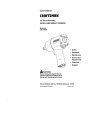
Owner's Manual
CRAFTSMIIN"
1/2" Drive Ultra-Duty
PISTOL GRIP IMPACT WRENCH
Model No.
235.199050
• Safety
° Operation
° Maintenance
° Service and
Adjustments
= Parts List
• Espa_oi
_WARNING:
Before using this Impact Wrench
read this manual and follow all its
Safety and Operating Instructions.
Sears, Roebuck and Co., Hoffman Estates, IL 60179
Owner'= M=nual P7360 (1-98) Printed In USA

TABLE OF CONTENTS
Two Year Warranty
Safety
Warning Labels
Notice, Warning and Caution
Placing Tool In Service
Using the Tool
Operation
Air Supplyand Connections
Using the Power Management System
Specifications
Maintenance
Lubrication
Service and Adjustment
Disassembly
Assembly
Troubleshooting
Parts List
Exploded Drawing
Parts for Ordering
PAGE
2
3-5
6-7
8-15
16
17-19
EspaSol 20-37
FULL TWO YEAR WARRANTY
If this product fails due to a defect in material or workmanship within
two years from the date of purchase, Sears will at its option, repair or
replace it free of charge.
Return this product to a Sears Service Center for repair,or to place of
purchase for replacement.
This warranty gives you specific legal rights, and you may also have
other rights which vary from state to state.
Sears, Roebuck and Co., Dept. 817WA, Hoffman Estates, IL 60179

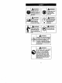
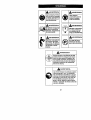
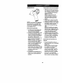
,_WARNING
Always wear eye
protection when op-
erating or perform-
ing maintenance on
this tool.
_WARNING
Always wear hear-
ing protection
when operating
this tool.
_._l_gl_ Do not use dam- Operate at 90 psig
aged, frayed or (6.2 bar/620 kPa)
deteriorated air Maximum air
hoses and fittings, i pressure.
Keep body stance Do not carry the
balanced and firm. tool by the hose.
Do not overreach
when operating this
tool.
,_WARNING
Always turn off the air supply
and disconnect the air supply
hose before installing, re-
moving or adjusting any ac-
cessory on this tool, or before
performing any maintenance
on this tool.
,_WARNING
Air powered tools can vibrate
in use. Vibration, repetitive
motions or uncomfortable
positions may be harmful to
your hands and arms. Stop
using any tool if discomfort,
tingling feeling or pain occurs.
Seek medical advice before
resuming use.
3

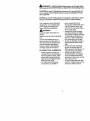
_WARNING is used to indicate the presence of a hazard which
can cause severe personal Injury or death if thewarning Is Ignored.
CAUTION is used to indicate the presence of a hazard which will
or can cause minor personal injury or property damage if the cau-
tion is Ignored.
NOTICE is used to notify people of installation, operation or main-
tenance information which is important but not hazard related.
This Craftsman Impact Wrench is
designed for use in general auto-
motive repair, tire service and
heavy duty fleet applications.
,_WARNING:
Important safety information en-
closed.
Read this manual before operating
tool.
It is the responsibility of an em-
ployer to place the information in
this manual into the hands of any-
one who operates this device.
Failure to observe the following
warnings could result in injury.
PLACING TOOL IN SERVICE
• Always operate, inspect and
maintain this tool in accordance
with all regulations (local, state,
federal and country), that may
apply to hand-held/hand-oper-
ated pneumatic tools.
• For safety, top performance,
and maximum durability of
parts, operate this toolat
90 psig (6.2 bar/620 kPa) maxi-
mum air pressure at the inlet
with 3/8" (10mm) inside diame-
ter air supply hose.
° Always turn offthe air supply
and disconnect the air supply
hose before installing, removing
or adjusting any accessory on
this tool, or before performing
any maintenance on this tool.
• Do not use damaged, frayed or
deteriorated airhoses and fit-
tings.
° Be sure all hoses and fittings
are the correct size and are
tightly secured. See Figure 1 for
a typical piping arrangement.
° Always use clean, dry air at
90 psig maximum air pressure.
Dust, corrosive fumes and/or
excessive moisture can ruin the
motor of an air tool.
° Do not lubricate tools with flamo
mable or volatile liquids such as
kerosene, diesel or jet fuel.

PLACING TOOL IN SERVICE
(continued)
• Do not removeany labels. Re-
place any damagedlabel.
• The use ofa hosewhip is rec-
ommended. A couplercon-
nected directlyto the air inletin-
creases toolbulkand de-
creases toolmaneuverability.
• For maximum performance, the
coupler on thewallshould be
the next size largerthan the
coupler usedon the tool.The
coupler closesttothe tool
should notbe lessthan the
proper air supplyhose size.
USING THE TOOL
• Always wear eye protection
when operatingor performing
maintenance on this tool.
• Always wear hearing protection
when operating this tool.
• Keep hands, loose clothing and
long hair away from rotating
end of tool.
• Note the position of the revers-
ing lever before operating the
tool so as to be aware of the
direction of rotation when oper-
ating the throttle.
• Anticipate and be alert for sud-
den changes in motion during
start-up and operation of any
power tool.
• Keep body stance balanced
and firm. Do not overreach
when operating this tool. High
reaction torques can occurat or
below the recommended air
pressure.
• Tool shaft may continue to ro-
tate briefly after throttle is re-
leased.
• Air powered tools can vibrate in
use. Vibration, repetitive mo-
tions or uncomfortable positions
may be harmful to your hands
and arms. Stop using any tool ff
discomfort, tingling feeling or
pain occurs. Seek medical ad-
vice before resuming use.
• Use accessories recommended
by Craftsman.
• Use only impact sockets and
accessories. Do not use hand
(chrome) sockets or accesso-
ries.
• Impact wrenches are not torque
wrenches. Connections requir-
ing specific torque must be
checked with a torque meter af-
ter fitting with an impact
wrench.
• This tool is not designed for
working in explosive atmo-
spheres.
° This tool is not insulated against
electric shock.
NOTICE: The use of other than
genuine Craftsman replacement
parts may result in safety hazards,
decreased tool performance, in-
creased maintenance, and may
invalidate all warranties.
Repairs should be made only by
authorized trained personnel.

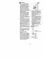
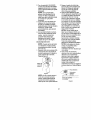
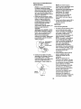
Air Supply and Connections
Always use clean dry air.Dust,
corrosivefumes and/or excessive
moisture can ruin the motor of an
air tool. An air line filter can greatly
increasethe life of anair tool. The
filterremoves dustand moisture.
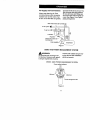
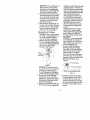
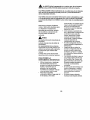
Besure all hoses and fittingsare
the correctsize and are tightlyse-
cured.See Figure1 for a typical
pipingarrangement.
Main lines 3 timesair toolinletsize.
Toairtool
Lubri
Branch line 2 times air - _ I [_ _1 I
toolinletsize _,,//_/-.-,- ,t =
Drainregulady_ Compressor_
Figure 1
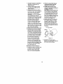
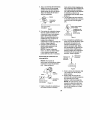
USING THE POWER MANAGEMENT SYSTEM
,_WARNING:
Airwrenches are nottorquecon-
trotdevices. Fastenerswith specif-
ictorquerequirementsmustbe
checked with suitabletorque mea-
suringdevices afterinstallation
with an air wrench.
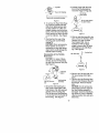
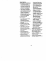
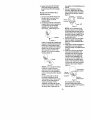
MODEL 19905 POWER MANAGEMENT SYSTEM
Power settingindicators
Minimum
Maximum
Power management dial
Figure2
6

YourImpactWrench incorporates
a Power Management System that
allows you to select four power
output settings. These settings
range from minimum power output
through maximum power output in
the forward direction only. The Air
Wrench will always operate at
maximum power output in the re-
verse direction, no matter what
power output level is selected.
AWARNING:
The fourpowersettingindicators
of increasingsize on the rear of
the housing are for reference only
and DO NOT denote a specific
power output. The smallest power
setting indicator designates mini-
mum power output, the two middle
power setting indicators denote
medium power outputs and the
largest power setting indicator de-
notes maximum power output.
The power output can be further
reduced in forward or reverse by
using the variable throttle. Air sup-
ply systems which do not deliver
adequate air pressure can affect
power output at all settings.
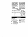
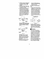
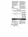
SPECIFICATIONS
Model Type of Drive Impacts
Handle per min.
19905
pistol 1/2'" 1,250
grip
LUBRICATION
Recomm'ended
Torque Range
Forward
ft.lb
50-400
(450 max.)
Forward
Newton
meter (Nm)
68-542
(610 max.)
Reverse
ft-lb
55O
(600 max.)
Reverse
Newton
meter (Nm)
746
(813 max,)
Use Craftsman No. 18830
Pneumatic Tool Care Kit or a good
quality SAE 20 or 20W motor oil.
Craftsman 18830 Oil
Craftsman 18830 Grease
for routine external lubrica-
tion of the impact mecha-
nism through the Hammer
Case Grease Fitting.
Always use an air line lubricator
with these tools.
CAUTION: Donot mark any
nonmetallic surface on this tool
with customer identification codes.
Such actions could affect tool per-
formance.
7

DISASSEMBLY
NOTICE: Numbers in paren-
theses in the following instruc-
tons are part illustration num-
bers found on pages 17-19.
General Instructions
1. Do not disassemble the tool any
further than necessary to re-
place or repair damaged parts.
2. Whenever grasping a tool or
part in a vise, always use lea-
ther-covered vise jaws to pro-
tect the surface of the part and
help prevent distortion. This is
particularly true of threaded
members and housings.
NOTICE: Always use lea-
ther-covered vise jaws when
clamping the handle in a vise.
Leather will conform to the
shape of the handle and allow
the tool to be held securely. To
prevent damage to the exhaust
diffuser, never clamp only the
bottom of the handle.
3. Do not disassemble the tool
unless you have a complete set
of new gaskets and O-rings for
replacement.
Disassembly of the Impact
Wrench
1. Clamp the handle of the impact
wrench in a vise with leather-
covered jaws withthe square
driver positioned horizontally.
NOTICE: Avoid excessive
clamping pressure which can
damage the Housing and can
cause difficulty when removing
the parts.
2. Unscrew and remove the four
Hammer Case Screws (11).
3. While lightly tapping on the end
of the Anvil (8) with a plastic
hammer, lift off the Hammer
Case (15) and Hammer Case
Gasket (18).
NOTICE: The Front End Plate
(2) might come off during the
removal of the Hammer Case.
Make sure that itdoes not drop
on the floor or strike a hard or
metallic surface since it might
be damaged.
4. Grasp the Hammer Frame (12)
and carefully lift off the entire
impact mechanism, making cer-
tain not to drop the two Ham-
mer Pins (13).
Disassembly of the Impact
Mechanism
1. Set the mechanism, driver end
up, on the workbench.
NOTICE: Note the twin ham-
mers within the Hammer
Frame. These are identical, but
must be placed in the Hammer
Frame in a certain relationship.
Using a felt-tipped pen, mark
the top "Tt" hammer and the
bottom hammer "Bt" with the
arrows pointing upward. Mark
both Hammers on the same
end.
2. With the mechanism sitting up-
right on the workbench, slowly
rotate the Anvil in a clockwise
direction until itcomes up solid.

NOTICE: If you continueto ro-
tate the Anvil, it will cam the
Hammers out of engagement.
Don't dothis; merely rotate the
Anvil until itcomes up solid.
3. Hold the Hammer Frame firmly
and without disturbing the ham-
mers, gently lift the Anvil while
simultaneously rotating it clock-
wise about 1/8 of a turn from
the Hammer Frame.
4. With the Anvil removed, lift out
the two Hammer Pins. The twin
hammers are now free to slide
from the Hammer Frame, Be
careful do not to drop them.
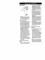
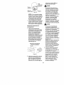
Disassembly of the Motor
NOTICE: When pulling, disas-
sembling or assemblingthe mo-
tor, we recommendreplace-
ment of the MotorGasket (7).
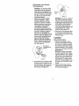
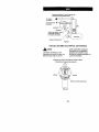
1. Remove the MotorAssembly
from the Housing(19) bypush-
ingon Power Management Dial
(41) from the backofthe
Housing. See Figure3.
Figure 3
NOTICE; If the Motor Assem-
bly cannot be removed from the
Housing by pushing, tap the
Power Management Dial lightly
until the Motor Assembly is free.
2. Remove the Power Manage-
ment Dial from the rear of the
Cylinder (1). Remove the Power
Management Dial Seal (42) if it
needs to be replaced.
3. Remove the Front End Plate (2)
from the Cylinder by tapping the
4,
splined end of the Rotor (5) with
a plastic hammer. If the Front
End Plate does not come loose,
secure a center punchin a vise
with the point angled downward
and outward from the vise.
Then, grasp the Cylinder and
Front End Plate in one hand
and position the hole in the end
of the Rotor against the punch.
NOTICE: Be careful not to
drop the Cylinder since it can
be damaged by hitting a hard
surface.
Using the other hand, tap the
punch with a hammer while
pressing the Rotor against the
punch. After a few taps, the
Front End Plate will slide off of
the Cylinder.
NOTICE: To prevent damage
to the Cylinder, do not tap or
strike Cylinder on a hard or me-
tallic surface when removing
the Rotor Bearings (3).
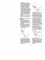
To remove the Front Rotor
Bearing, hold the Front End
Plate with Front Rotor Bearing
down and tap the Front End
Plate on a flat, nonmetallic
surface such as a work bench.
This will loosen the Front Rotor
Bearing so that it will drop out of
the Front End Plate. See
Figure 4.
Front end plate
Front rotor bearing
Bench with nonmetallic surface
Figure 4
5. Remove the Rear Rotor Bear-
ingRetainer(6) from therear of
the Rotor (5). The Rotor can
now be removed from the Cylino
der. Remove the Vanes (4) from
the Rotor if they need to be re-
placed.

_ Cylinder
e
Rear rotor bearing
Bench with nonmetallic surface
Figure 5
6. To remove the Rear Rotor Bear-
ing, hold the Cylinder with the
Rear Rotor Bearing down and
tap the Cylinder on a flat, non-
metallic surface such as a work
bench. This will loosen the Rear
Rotor Bearing so that it will drop
out of the Cylinder. See Figure
5.
7. Working from the rear of the
Housing, push out the Motor
Gasket (7).
NOTICE: When removing the
Motor Gasket, do not use a
screwdriver or any other sharp
object which could damage the
Gasket and/or Housing.
Disassembly of the Throttle
Mechanism
NOTICE: For ease of disas-
sembly, we recommend using
the inlet Clip Removal Tool (43).
See Figure 6.
2. Pull theTrigger (33) from the
front of the Housing and re-
move the Trigger O-ring (34).
SIotfortab
Tab on inlet retainer
clip (both sides)
Figure 7
3. With the Inlet Bushing stillinthe
vise, remove the Tilt Valve Seat
Retainer (31) and Tilt Valve
Seat Support (30). Use a
hooked tool with no sharp
edges to remove the Tilt Valve
Seat (29) from the Inlet Bush-
ing. See Figure 8.
Hooked tool
Tilt valve stem
Left-hand
button
Inlet bushing
Inlet clip removal assembly
tool
Figure 6
1. Secure the Inlet Bushing in a
vise. Press in both tabs of the
Inlet Retainer Clip (32) and pull
upward on the Housing (19).
This will allow the Inlet Bushing
to comefree from the Handle of
the Housing. See Figure 7.
.
5°
Figure 8
Remove theTilt Valve (28) and
-lilt Valve Spring (27) if dam-
aged.
Remove the inlet Bushing Seal
(26) and Inlet Retainer Clip (32)
if damaged. Remove Washer
(25).
NOTICE: Do not remove the
Inlet Bushing Screen (23) from
the Inlet Bushing unless it is
damaged. Cleanthe Inlet Bush-
ing Screen by using a suitable
cleaning solution in a well venti-
lated area.
10

Disassembly of the Reverse
Valve Mechanism
NOTICE: The Reverse Valve
Assembly cannot be removed
without first removing the For-
Reverse
ward and Reverse Buttons (39) valve
and (40). Therefore, it is impor-
tant that the procedure below
be followed exactly.
1. Notice the notches on either
side of the partition. These
notches indicate the correct
location for insertion of a thin-
bladed screwdriver used for re-
moving the Forward and Re-
verse Buttons. Insert the
screwdriver between the parti-
tion and the Button which is fully
extended. Gently pry against 3.
the Button to disengage the
detent so that the Button can be
removed. After the Button is re-
moved, reach inside the Hous-
ing and rotate the Reverse
Valve to extend the remaining
Button. Repeat the above pro-
cedure for the remaining But-
ton. See Figure 9.
Removal of
_ _°uttrWoard/reverse
Figure 9
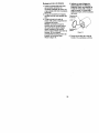
2. Insert thumb into the front of the
Housing and push down on the
Reverse Valve so that it can be
removed through the bottom of
the handle. See Figure 10.
Figure 10
NOTICE: Do not try to remove
the Reverse Valve by pushing
upward. It can only be removed
by pushing it downward and out
of the bottom of the handle. If
the Reverse Valve does not
come free, tap the bottom of the
handle lightly with a rubber
hammer until it drops out.
Remove the Top Reverse Valve
O-ring (36) and the Bottom Re-
verse Valve O-ring (37) from the
Reverse Valve.
ASSEMBLY
General Instructions
1. Whenever grasping a toolor
part in a vise, always use leath-
er-covered vise jawsto protect
the surface ofthe part and help
prevent distortion.This ispartic-
ularlytrue ofthreaded members
and housings.
NOTICE: Always use leather-
covered visejaws when clamp-
ingthe handle ina vise, Leather
willconformtothe shape ofthe
handle and allowthetooltobe
heldsecurely.To prevent dam-
age to the exhaust diffuser, nev-
er clamp only the bottom of the
handle.
2. Always clean every part and
wipe every part with a thin film
of oil before installation.
11

NOTICE: Do not remove
grease from theimpact mecha-
nismor Hammer Case (15). If
the impactmechanism has not
been disassembled,inject
Craftsman No. 18830 Grease
throughthe Hammer Case
Grease Fitting(17). When dis-
assemblingand assemblingthe
impactmechanism,remove all
grease from the impactmecha-
nism and Hammer Case and lu-
bricatethe impactmechanism
and Hammer Case Bushing
(16) with Craftsman No. 18830
Grease.
3. Apply a filmofo-ringlubricantto
all O-rings beforefinal assem-
bly.
Assembly of the Reverse Valve
Mechanism
1. Install the Bottom Reverse
Valve O-ring (37) (color-coded
blue) and theTop Reverse
Valve bring(36) on the Reverse
Valve (35).
2. Insertthe Reverse Valve in the
bottomof thehandle making
sure thattwoears on the Re-
verseValve are facing down-
ward.See Figure11.
Dowel
Figure12
NOTICE: If the Reverse Valve
is pushed up too far and be-
comes wedged, itwillhave to
be pushed backdownthrough
the the handleand reinserted
from the bottomof the handle.
The Reverse Valve cannot be
removed by pushing it up
through the handle and into the
motor bore. If the Reverse
Valve must be removed and re-
installed, make sure that the
Top and Bottom Reverse Valve
O-rings have not been rolled off
and are in their proper positions
on the Reverse Valve.
3. When the Reverse Valve has
been installed, rotate the Re-
verse Valve so that the tab on
the Reverse Valve is at the rear
I
of the Housing. See Figure 13.
/_ Ears
Figure 11
Use a wooden dowel to push
the Reverse Valve up through
the handle until the top of the
Reverse Valve is flush with or
slightly above the bottom of the
motor bore in the Housing (19).
See Figure 12.
Reverse valve
__ Front of
housing
Approx, 1/32
Figure13
NOTICE: !f the orientation of
the Reverse Valve is not correct
(tab facing the the rear of the
Housing), the Trigger (33) and
the Forward and Reverse But-
tons (39) and (40) cannot be
installed.
12

4. Install the Trigger O-ring (34) on
the Trigger. Insert the Trigger
Assembly in the front of the
Housing.
5. Rotate the Reverse Valve in ei-
ther direction until an ear comes
up against the Trigger.
6. Look through the Housing from
the rear. If the tab on the Re-
verse Valve has been rotated to
the left, install the right Button
in the Housing. When one But-
ton has been installed, push the
Button in. This will rotate the'
Reverse Valve so that the other
Button can be installed. See
Figure 14.
Reverse /,<__ Rear of
valve _J housing
Tab-"'- _ Forward
button
Figure 14
If the tab on the reverse Valve
has been rotated to the right,
install the leftButton. See Fig-
ure 15.
_ Rear of
Reverse\ _usin9
valve "__-
Rever_e _ _ Tab
button
Figure 15
NOTICE: If the Forward/Re-
verse Buttons will not install
easily, move the Reverse Valve
slightly higher in the handle to
provide better alignment with
the Buttons.
7. After the Forward/Reverse But-
tons have been installed, re-
move the Trigger before pro-
ceeding with installation of the
throttle mechanism.
Assembly of Throttle Mecha-
nism
,
Using an Inlet Bushing Screen
Installation Tool, install the Inlet
Bushing Screen (23), screened
end first, in the bottom (hex
end) of the Inlet Bushing (22).
Insert the rounded end of the
tool in the cone formed by the
screen and tap the end of the
tool to secure the rim of the
screen in the Bushing. See Fig-
ure 16.
Inlet Bushing Screen
installation Tool
Figure 16
2. Install the Washer (25), Inlet
Retainer Clip (32), inlet Bushing
Seal (26), Tilt Valve Spring (32),
Tilt Valve (27) Tilt Valve Seat
(29) and Tilt Valve Seat Support
,_3o).
WARNING:
The "131tValve Seat Retainer
(31) must be properly installed
in the groove in the Inlet Bush-
ing (22). To check for correct
installation of the Retainer, in-
sert a pin into one of the holes
in the Retainer and rotate the
Retainer. A correctly installed
Retainer will rotate freely but
with some resistance in the
groove of the Inlet Bushing. An
incorrectly installed Retainer will
pop out of the Inlet Bushing
when the Retainer is rotated,
13

_WARNING:
Do not usecompressed air to
check installationofthe Tilt
Valve Seat Retainer or Inlet
BushingScreen unlessthe en-
tire Inlet BushingAssembly is
installedinthe toolwiththe
Hammer Case installedand
properlysecuredto the Motor
Housing.Failureto do so could
resultin injury.Install the Tilt
Valve Seat Retainer.
NOTICE: When re-installing
the InletBushingAssembly
(22), pullthe Trigger (33) out-
ward and make sure thatthe
Reverse Button (40) is de-
pressedbeforesnapping the In-
letBushingAssembly back into
the Housing,
3. Installthe InletBushingAssem-
blyby pushingit intothe hole in
the Housinguntilyou see and
hear the tabson Inlet Retainer
Clipsnap intoplace throughthe
slotsin Housinghandle.
NOTICE: The Reverse Button
(left) (40) mustbe pushedin be-
fore the Triggercan be
installed. Otherwise, theTrigger
will be damaged during installa-
tion.
4. Install the Trigger by pushing it
into the handle until a click is
heard indicating that it is prop-
erly engaged.
Assembly of the Motor
NOTICE: When disassem-
bling, assembling or pulling the
Motor, we recommend replace-
ment of the Motor Gasket (7).
1. Install the Motor Gasket in the
Housing making sure that the
grooves in the tab of the Motor
Gasket fit around ridge in the
Housing. See Figure 17.
Installation
..i-....... -... ofmotor
7 ".
/" \, gasket
"_ ":i]ii -'_
//5 /..i!:_:_ 't
l_:.!.:_" .i.._i i
_- !!_,..'%. I
",,_::_,_,_....:,:.=:-.-..:--•
Figure 17
2. Install the Rotor Bearing (3) into
the rear of the Cylinder (1).
3. Install the Rotor in the Cylinder
and secure with the Rear Rotor
Bearing Retainer (6).
4. Install Vanes (4) in the slots in
the Rotor (5).
5. Install the Rotor Bearing (3) into
the Front End Plate (2). Install
the Front End Plate on the Cyl-
inder by pressing on the inner
race of the front Rotor Bearing
until the Bearing isseated on
the Rotor Shaft,
6. Install the Power Management
Dial Seal (42) on the Power
Management Dial (41) and
installthe Dial inthe end ofthe
Cylinder.
Assembly of the Impact
Mechanism
;_-_r] Tophammer
notohon
Bottom hammer
haft-round notchon left
Figure 18
14

1. Coat the Hammers (14) with a
light film of Craftsman No.
18830 Grease.
2. Heavily coat the jaws of the
Anvil (8) with Craftsman No.
18830 Grease.
3. Replace the Hammers Inthe
Hammer Frame (12) exactly as
they were when you marked
them prior to disassembly.
NOTICE: If you are installing
new Hammers or want to
change the location of the exist-
ing Hammers to utilize both im-
pacting surfaces, slide the
Hammers in the Hammer
Frame so that the half-round
notch on one Hammer is lo-
cated on one side of the Frame
and the half-round notch on the
other Hammer is located on the
other side of the Frame.
4. Replace the Hammer Pins (13).
5. Examine the baseof the Anvil
(8) and note its contour. While
looking down through the Ham-
mer Frame, swing the top Ham-
mer to its full extreme one way
or another until you can match
the contour of the Anvil. Enter
the Anvil into the Hammer
Frame and through the first
Hammer. Swing the bottom
Hammer in the opposite direc-
tion from the top Hammer and
maneuver the Anvil slightly until
it drops into the bottom Ham-
mer. See Figure 18.
Assembly of the Air Wrench
1. Position the Motor Housing (19)
in leather-covered vise jaws
with the splined shaft of the
Rotor in a horizontal position.
2. Place the assembled impact
mechanism down ontothe
splined hub of the Rotor.
3. Position the Hammer Case
Gasket (18) against the face of
the Motor Housing.
NOTICE: Be sure that the flat
on the bottom of the Hammer
Case Gasket is installed in the
corresponding flat in the Hous-
ing. If the Hammer Case Gas-
ket is not installed correctly, the
Air Wrench will not function
properly. See Figure 19.
4. Apply a thin film of Craftsman
No. 18830 Grease on inside
surface of the Hammer Case
Bushing (16), and place the
Hammer Case (15) down over
the Anvil and against the Motor
Housing.
5.
Front of housing
Figure 19
Install the Hammer Case
Screws (11) and tighten them to
25 in-lb (2.8 Nm) torque.
15

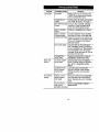
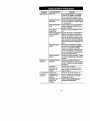
Trouble Probable Cause Solution
Low power DryMotor Daily, inject3 cc ofCraftsman No.
18830 Oil intotheinletand runthe
tool to lubricate the motor.
Inadequate air Install proper air supply and connec-
supply tion. Refer to Figure 1 on Page 5.
Dirty Inlet bushing Using a clean, suitable, cleaning
Screen solution in a well ventilated area,
clean the Inlet Bushing Screen.
Replace a complete set of Vanes
Motor will
not run
Toolwill not
impact
Worn or broken
Vanes
Worn or broken
Cylinder and/or
scored End Plates
Dirty motor parts.
Damaged Re-
verse Valve
Incorrect assem-
bly of motor
Insufficient lubri-
cant in impact
mechanism.
Broken or worn
impact mecha-
nism parts
Impact mecha-
nism not as-
sembled correctly.
Examine Cylinder. Check outside
and ends for wear or damage and
inside for scored or wavy bore. Re-
place Cylinder if any of these condi-
tions exist. Replace End Plates if
they are scored.
Disassemble the Tooland clean
with a suitable, cleaning solution in
a well ventilated area. Assemble the
Tool and inject 3 cc of the recom-
mended oil into Inlet and run Tool to
lubricate internal parts.
Replace Reverse Valve. Refer to
Installation of Reverse Valve.
Disassemble motor and replace
worn or broken parts and reassem-
ble. Refer to Assembly of the
Motor.
Lubricate impact mechanism
through Hammer Case Grease
Fitting using the recommended
grease.
Remove Hammer Case Assembly
and examine impactmechanism
parts. Replace any worn or broken
parts.
Refer to Assembly of Impact
Mechanism.
16

\
\
\
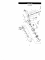
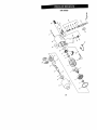
235.199050
\
\
\
\
\
\
\
\
\
\
\\
\ -
\
\
\
\
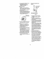
17

...&
CO
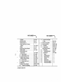
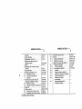
PART NUMBER'-'---_ PART NUMBER-'--_
+
+
+
1
2
3
4
5
6
7
8
9
10
11
12
13
14
15
16
C_,linder ...........................
Front End Plate ....................
Rotor Bearing (2) ...................
Vane Packet (set of 6 Vanes)
(yellow) ...........................
Rotor .............................
Rear Rotor Bearing Retainer .........
Motor Gasket ......................
Anvil Assembly (1/2"
square drive) .......................
Socket Retainer ..................
Socket Retainer O-ring ............
Hammer Case Screw (4) ............
Hammer Frame Assembly ...........
Hammer Frame ..................
Hammer Frame Pin (2) ............
Hammer(2) ........................
Hammer Case Assembly ............
Hammer Case Bushing ..........
2131-3A
2131-11
2131-97
2131-42A-6
2131-53
2131-6
2131-283
2131 -A626
231-425A
R1A-159
2131-638
2131 -A703
2131-703
2131-704
2131-724
SN2131-D727
2131-941
17
+ 18
19
20
21
22
23
24
25
26
27
28
29
3O
31
Hammer Case Grease
Fitting ...................
Hammer Case Gasket .......
Housing Assembly ..........
Nameplate ...............
Housing Label ............
Inlet Bushing Assembly ......
Inlet Bushing .............
Inlet Bushing Screen ....
Inlet Parts Kit .............
Washer ................
Inlet Bushing Seal .......
Tilt Valve Spring ........
Tilt Valve ...............
Tilt Valve Seat ..........
Tilt Valve Seat Support...
Tilt Valve Seat Retainer ..
DOF9-879
2131-36
CR2131-B40
CR2131-301
CR2131-99
2131 -A565
2131-565
5RA-61
2131-1(303
+ includedin Hammer Kit.

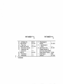
PART NUMBER-"--_ PART NUMBER--'-'_
32
33
34
35
36
37
38
39
40
Inlet Retainer Clip ..........
Trigger Assembly ............
Trigger O-ring .............
Reverse Valve Assembly .....
Reverse Valve O-ring (top) ..
Reverse Valve O-ring
(bottom) (blue) ............
Button Kit ...................
Forward Button ............
Reverse Button ............
2131-57
2131 -A93
2131-A329
2131-K75
.
41
42
43
_t
Power Management
Assembly ..................
Power Management
Dial Seal .................
Inlet Clip Removal Tool .......
Craftsman Pneumatic Tool
Care Kit (Oil, Grease) (Available
through Craftsman ®Catalog) ..
Owner's Manual .............
Hammer Kit .................
2131 -A249
2131-322
9-18830
P7350
2131-THK1
* Not illustrated.

GARANT_ TOTALDEDOSANOS
Si este producto fallara debldo a un defecto en el material de fabricacibn
o la mano de obra dentro de los dos afios a partir de la fecha de
adquisicl6n, Sears Io reparard o sustituird, seg_n consldere oportuno,
sin cargo.
Entregueel productoenun centro de servlcio Searsparasu reparaci6n,o
en el lugar donde se compr6 para camblarlo porotro.
Esta garantfa le otorga derechos legales especfficos, y puede que tenga
ademds otros derechos que varfan de un estado a otro.
Sears, Roebuck and Co., Dept. 817WA, Hoffman Estates, IL 60179, EE.UU.
de Am6rica
2O

AADVERTENC_
Usar siempre protenc-
ci6n ocular al manejar
o realizar operaciones
de mantenlmlento an
esta herramlenta.
@
_AADVERTENCIA
Usar siempre
proteccl6n para los
oidos al manejar
esta herramienta.
No utllizar mangueras Manejar la herramlen-
de aire y accesorios ta a una presi6n de
da6adoe, desgastados aire m_xima de 90
ni deterlorados, psig (6,2 bar/620 kPa)
Mantener una postura No coger Is herra-
del cuerpo equilibra- mienta por la man-
da y firme. No estirar guera paralevantaria.
demasiado los brazos
al manejar la herra-
mienta.
AADVERTENCIA
! Cortar siempre el suministro de alre
y desconectar la manguera de sumi.
nistro de aire antes de instaler, reti-
rar o ajustar cusiquier accesorlo de
esta herramienta, o antes de realizar
cuslquler operaci6n de mantenimi-
ento de la misma.
ADVERTENCIA
Las herramlentas neum_ticas pueden
vibrar durante il uso. La vibracl6n,
los movimientos repetitivos o las po-
siciones inc6modas podrien da6arie
los brazos y las manos. En caso de
Incomodldad, sensaci6n de homi-
gueo o dolor, dejar de usar la herra-
mienta. Consultar al m_dico antes de
voiver a utilizaria.
21

_lk Un AVISO indlca la presencla de un peligro que, de no hacerse
caso al aviso, puede provocar graves lesiones o incluso la muerte.
Una PRECAUCI6N indica la presencia de un peligro que, de no hacerse
caso al aviso de precauci6n puede provocar o provocar_ lesiones o
da_os materlales menores.
Una NOTA sirve para comunicar informacibn sobre la instalaci6n, el uso
o el mantenimiento que es importante pero qua no afecta la seguridad.
Los avisos de peligro no se deben nunca Incluir bajo el encabezamiento
NOTA.
Esta Ilaves de impactoCraftsman
modelo 19905 est_.ndiseSadas para
su utilizaci6n en reparaciones
generales de automSviles, revisi6n
de neumdticos y aplicaciones de
servicio pesado en flotas de
veh[culos.
,_AVISO:
Se adjunta informaci6nimportante de
seguridad.
Lea este manual antes de utilizar la
herramienta.
Es responsiabilidadde la empresa
asegurarse de que toda persona que
utilice la herramienta est_ al tanto de
la informaci6n que contiene este
manual.
El hacer caso omiso de los avisos
siguientes podda ocasionar lesiones.
PARA PONER LA
HERRAMIENTA EN SERVICIO
• Utilice, inspeccione y mantenga
esta herramienta siempre de
acuerdo con todas las normativas
locales y nacionales que se
apliquen alas herramientas
neumdticas de utilizaci6n manual
o que se sujeten con la mano.
• Para mayor seguridad,
rendimiento 6ptimo y larga vida _til
de las piezas, utilice esta
herramienta a una presi6n de aire
mdxima de 90 psig (6,2 bar/620
kPa) con una manguera de
suministro de aire con di_.metro
interno de 10 mm.
• Corte siempre el suministrode
aire y desconecte la manguera de
suministro de aire antes de
instalar, desmontar o ajustar
cualquier accesorio de esta
herramienta, o antes de realizar
cualquier operaci6n de
mantenimiento de la misma.
• No utilice mangueras de aire y
racores daSados, desgastados o
deteriorados.
• AsegSrese de que todos los
racores y mangueras sean del
tamaSo correcto y est_n bien
apretados. La Figura 1 muestra
una disposiciSn caracter{stica de
las tuberfas.
• Use siempre aire limpio y seco a
una presi6n mdxima de 90 psig
(6,2 bar/620 kPa). El polvo, los
gases corrosivos y el exceso de
humedad pueden estropear el
motor de una herramienta
neum&tica,
• No lubrique las herramientas con
Ifquidos inflamables o void.tiles
tales como queroseno, gasoil o
combustible para motores a
reacci6n.
• No saque ninguna etiqueta.
Sustituya toda etiqueta daSada,
22

PARA PONER LA
HERRAMIENTA EN SERVICIO
• Se recomienda la utilizaci6n de
una conexi6n flexible para
manguera de aire. Si se conecta
un acoplador directamente a la
salida de aire, se aumentard el
volumen de ta herramienta y se
disminuird su maniobrabilidad.
• Para conseguir un rendimiento
6ptimo, el acoplador situado en la
pared deberd ser mds grande, del
tamaSo siguienteal del acoplador
utilizado en la herramienta. El
acoplador mds cercano a la
herramienta no debe ser menor
que el tamaSo de la manguera de
suministro de aire apropiada.
UTILIT__ACION DE LA
HERRAMIENTA
• Lleve siempre protecci6n ocular
cuando utilice esta herramienta o
realice operaciones de
mantenimiento en la misma.
• Lleve siempre protecci6n para los
ofdos cuando utilice esta
herramienta.
• Mantenga las manos, la ropa
suelta y el cabello largo alejados
del extremo giratorio de la
herramienta.
• Tome nota de la posici6n de la
palanca de inversi6n antes de
hacer funcionar la herramienta
para tener en cuenta el sentido de
rotaci6n al accionar el
estrangulador.
• Anticipe y est_ atento a los
cambios repentinos en el
movimiento durante la puesta en
marcha y utilizaci6n de toda
herramienta motorizada.
• Mantenga una postura del cuerpo
equilibrada y firme. No estire
demasiado los brazos al manejar
la herramienta. Pueden darse
elevados pares de reacci6n a la
pre.si6n de alre recomendada, e
incluso a presiones inferiores.
• El eje de la herramienta puede
seguir girando brevemente
despu_s de haberse soltado la
palanca de mando.
• Las herramientas neumdticas
pueden vibrar durante el uso. La
vibraci6n, los movimientos
repetitivos o las posiciones
inc6modas pueden daSarle los
brazos y manos. En caso de
incomodidad, sensaci6n de
hormigueo o dolor, deje de usar la
herrarnienta. Consulte con el
m_,dico antes de volver a utilizarla.
- Utilice 5nicamente los accesorios
Craftsman recomendados.
• Utilice 5nicamente bocas y
accesorios para llaves de impacto.
No Lrtilicebocas o accesorios
manuales (cromados).
• Las Ilaves de impactono son
Ilaves de par. Las uniones que
requieran pares espec{ficos
deberdn ser comprobadas con un
torsi6metro despu_s de haberlas
fijado con una Ilave de impacto.
• Esta herramienta no ha sido
diseSada para trabajar en
ambientes explosivos.
• Esta herramienta no estd aislada
contra descargas el_ctricas.
NOTA: El uso de piezas de
recambio que no sean las autdnticas
piezas Craftsman puede poner en
peligro la seguridad,reducir el
rendimiento de la herramienta y
aumentar los cuidadosde
mantenimiento necesarios, as{ como
invalidar toda garanfia.
Las reparaciones s61ose deben
encomendar a personal debidamente
cualificado y autorizado.
23

Tuber[as pdncipales3 veces el tamafio de
entradade herramientaneum&tJca
AI sistema _1 _,
neum&tJco
A la herramienta
neum&tJca
Lubricador
Regulador
Tuberfa de ramal 2 veces el
tarna6o de entrada de
herramienta neum_,tJca
Purgar peri6dicamente
Figura 1
Compresor
USO DEL SISTEMA DE CONTROL DE POTENCIA
,_AVISO:
Las Ilaves neum&ticasno son
dispositivosde controlde par. Las
fijaciones que exijan un par de
apriete espec{fico se deber&n
comprobar con un dispositivo
apropiadode medici6n de par
despu_s de haberlas apretado con
una Ilave neum&tica,
Sistema de controlde potencia modelo 19905
Indicadores de ajuste de potencia
Mfnima
Mando de controlde potencia
Figura 2
24

La Ilave de impactotiene incorporado
un sistema de controlde potencia
que permite seleccionar entre cuatro
ajustes de potencia. Estos ajustes
van desde potencia m{nima haste
potencia mdxima en el sentido de
giro a derechas solamente.
La Ilave neum&ticasiempre
funcionar_, con la mdxima potencia
en el sentido inverso, cualquiera que
sea el nivel de potencia
seleccionado.
_AVISO:
Los cuatro indicadores de potencia
de creciente tama_o situados en la
parte posterior de la carcase sirven
solamente de referencia;
NO indican una potenciaespecifica.
El indicadorde potenciam&s
peque5o seSala la potenciamfnima,
losdos indicadores de potencia
intermedios seSalan potencies
intermediasy el indicadorm&s
grande representa la m_xima
potencia.
La potencia puede reducirse aun m&s
con accionamiento a derechas o a
izquierdas mediante elgatillo de
mando. Los sistemas de aire
comprimido que no suministren aire a
la presiTn apropiada pueden afectar
la potencia en todos los ajustes.
Modelo
19905
ESPECIFICACIONES
Tipo de
empufiadura
Empufiadura
de pistola
Acciona-
mlento
1/2 pulg
Impactos
por
minuto
1,250
Game de par
recomendada
Sentido Sentido
normal Inverso
ft-ib ft-ib
50-400 550
!(450 mdx.) (600 m_x.)
Sentido Sentido
normal inverso
Nm Nm
(Newton (Newton
metros) metros)
68-542 746
(810 mdx.) (813 m_x.)
LUBRICACION
Utilice el kit Craftsman N-°18830 para
el cuidado de herramientas
neum_.ticas5 una buena clase de
aceite SAE20 6 20W paral el motor.
Acelte Craftsman N° 18830
Grasa Craftsman N° 18830
para lubricaciTn externa
_,-_ periddica del mecanismo
impulsor a tray,s del
engrasador de la carcase de
mazas.
Utilice siempre un lubricante de aire
comprimido con esta herramienta.
PRECAUClON: No marque
ninguna superficie no met&lica de
esta herramienta con los cTdigos de
identificaciTn del cliente. Tal acci6n
podrfa afectar al rendimiento de la
herramienta.
25

DESMONTAJE
NOTA: Los nSmeros que aparecen
entre par6ntesis en las siguientes
instrucciones corresponden a los
nSmeros de la ilustraci6n de piezas
en las p&ginas 35-37.
Instrucciones generales
1. No desarme la herramienta mds
de Io necesario para sustituir o
reparar las piezas dar_adas.
2. AI sujetar una herramienta o pieza
en un tornillode banco, utilice
siempre mordazas recubiertas de
cuero para proteger la superficie
de la pieza y evitar que se
deforme, sobre todo al tratarse de
piezas rosoadasy carcasas.
NOTA: AI sujetar la empuSadura
en un tornillode banco, utilice
siempre mordazas recubiertas de
cuero. El cuero se ajustar& a la
forma de la empuSadura y
permitir_ sujetar bien firme la
herramienta. Para evitar ocasionar
daSos al difusor de escape, no fije
nunca en el tornillo de banco s61o
el extremo inferior de la
empuSadura.
3. No desarme la herramienta si no
dispone de un juego completo de
juntas nuevas para sustituir las
actuales.
Desmontaje de la Ilave de Impacto
1. Sujete la empur_adura de la Ilave
de impacto en un tornillo de banco
con mordazas cubiertas de cuero,
con el cuadradillo de la Ilave en
posici6n horizontal.
NOTA: Evite el uso de una
presi6n de fijaci6n excesiva, Io
cual puede daSar la carcasa y
dificultar el desmontaje de las
piezas.
2. Desenrosque y saque los cuatro
tomillos de la caja de mazas (11).
3. Golpee ligeramente con un martillo
de pl&stico el extremo del yunque
(8) mientras retira la caja de
mazas (15) y la junta de la caja
(18).
NOTA: Es posible que la placa
delantera (2) se salga al retirar la
caja de mazas. AsegSrese de que
no se caiga al piso ni se golpee
contra una superficie dura o
met&Uca, ya que puede daSarse.
4. Sujete el bastidor de mazas (12) y
reUre con cuidado el mecanismo
de impacto entero, cercior&ndose
de que no se caigan los dos
pasadores de las mazas (13).
Desmontaje del mecanismo de
impacto
1. Ponga el mecanismo sobre el
banco de trabajo con el cuadradillo
hacia arriba.
NOTA: Observe las dos mazes
en el bastidor de mazas, f:stas
son id6nticas, pero deben
colocarse en el bastidor en una
posiciSn determinada. Utilice un
marcador para seSalar la maza
superior con una "S{"y la inferior
con una "1t", con las flechas
apuntando hacia arriba. Marque el
mismo extremo de ambas mazas.
26

2. Con el mecanismo en posici6n
vertical sobre el banco de trabajo,
haga girar lentamente el yunque
hacia la derecha hasta que quede
bloqueado.
NOTA: Si el yunque sigue
girando,bar& desengranar las
mazas. Por ello, el yunque se
debe hacergirar solamente hasta
el momento en que quede
bloqueado.
3. Sujete bien firme el bastidorde
mazas y, sin mover las mazas,
levante con cuidado el yunque,
haci_ndolo giraral tiempo hacia la
derecha un 1/8 de vuelta
aproximadamente, para sacarlo
del bastidor.
4, Una vez desmontado el yunque,
saque los dos pasadores de las
mazas. Las dos mazas ban
quedado libres ahora para
deslizarse del bastidor.Tenga
cuidado de que no se caigan.
Desmontaje del motor
NOTA: Cuando se tire del motor
o se desarme y vuelva a armar,
recomendamos sustituirla junta
det motor (7).
1. Saque el motor de la carcasa (19)
presionando sobreel mando de
controlde potencia (41) desde la
parte posterior de la carcasa.
V_ase la figura 3.
Mando de
control de
potencia
Figura3
NOTA: Si no se puede sacar el
motor de la carcasa haciendo
presi6n, golpee ligeramente el
mando de control de potencia
hasta que el motor quede liberado.
2. Saque el mando de controlde
potencia de la parte posteriordel
cilindro (1). Saque el ret_n del
mando de control depotencia
(42), si hay que sustituirlo.
3, Quite la placa delantera (2) del
cilindrogolpeando ligeramente con
un martillo de pl&sticoel extremo
estriado del rotor(5). Si no se
afloja la plata delantera, asegure
en el tomillo de bancoun botador
de centrado con la punta inclinada
hacia abajo y hacia fuera respecto
al tornillo. Sujete el cilindroy la
placa delantera con una mano y
sitLieel orificio en elextremo del
rotorcontra el botador.
NOTA: Tenga cuidadode no
dejar que se caigael cilindro,ya
que el mismo puede daSarse si se
golpea contra una superficiedura.
Con la otra mano martille
ligeramente el botadormientras
empuja el rotor contra el botador.
Tras unos golpes la placa
delantera se deslizar&del cilindro.
NOTA: Evite golpear elcilindro
contra una superficiedura o
met_.lica al extraer los
rodamientos del rotor (3) para que
no se dale.
4. Para extraer el rodamiento
delantero del rotor,sujete la placa
delantera con el rodamiento
delantero hacia abajo y golpee
ligeramente la placa delantera
sobre una superficieplana y no
met_lica tal como unbanco de
trabajo. Esto aflojar_,el
rodamiento de modo que caiga de
la placa delantera, V_ase la flgura
4.
'_ Placa delantera
Rodamiento
delantero
del rotor ,
Banco de supe_cie . "
no met_,lica
Figura 4
27

5. Saque el retenedor del rodamiento
trasero del rotor (6) de la parte
posterior del rotor (5). Ahora se
puede extraer el rotor del cilindro.
Saque las aletas (4) del rotor si
hay que sustituirlas.
_ Cilindro
Rodamiento
trasero del
rotor
Bancodesuperlicie
nomet&lica
Figura 5
6. Para extraer el rodamiento trasero
del rotor, sujete el cilindro con el
rodamiento trasero hacia abajo y
golpee ligeramente el cilindro
sobre una superficie plana y no
met_lica tal como un banco de
trabajo. Esto aflojar_, el
rodamiento de modo que caiga del
cilindro. V_ase la figura 5.
7. Empuje la junta del motor (7)
desde la parte posterior de la
carcasa para sacarla,
NOTA: AI quitar la junta del
motor, no utilice un destornillador
ni otro objeto puntiagudo qua
pueda daSar la junta o la carcasa.
Desmontaje del mecanismo de
estrangulaci6n
NOTA: Para facilitar el
desmontaje recomendamos utilizar
el extractor de clips de admisi6n
(43), V_ase la figura 6,
_ Bot6n
admisidn
Extractordelclip
de laentrada
Figura 6
1. Sujete el casquillo de admisi6n en
un tornillo de banco. Presione
2,
hacia dentro ambas leng_etas del
clipde retenci6n de la entrada (32)
ytire haciaarriba de la carcasa
(19). EIIopermitir& qua el casquillo
de admisi6n se liberede la
empufiadura de la carcasa, V_ase
la figura 7.
Tire del gatillo (33) para separarlo
de la parte delantera de la carcasa
y quite la junta t6rica del gatillo
(34).
Ranura para leng0eta
•(amboslados)
Leng_Jetaen clip
de retenci6n de la
entrada
(ambos lados)
3,
Figura 7
Con el casquillo de admisi6n alan
sujeto en el tornillo de banco, quite
el retenedor del asiento de la
v&lvula de inclinaci6n (31) y el
soporte del asiento (30). Utilice
una herrarnienta con gancho que
no tenga aristas cortantes para
extraer el asiento de la v&lvula de
inclinaci6n (29) del casquillo de
admisi6n. V_ase la figura 8.
jf _ Herramienta
V&stago de la _ con gancho
v_lvula de _
inclinacidn_
Figura 8
4,
5°
Quite la v&lvula de inclinaci6n (28)
y el muelle de la v_.lvula (32) si
est_.n daSados.
Quite el ret_n del casquillode
admisi6n (26) y el clip de retenci6n
de la entrada (27) si est_n
daSados. Quite la arandela (25).
NOTA: No quite el tamiz (23) del
casquillo de admisi6n salvo que
est_ daSado, Limpie el tamiz con
soluci6n de limpieza en un lugar
bien ventilado.
28

Desmontale del rnecanismo de la
v_lvula inversora
NOTA: No se puede desmontar
la vdlvula inversora sin antes
desmontar los botones de sentJdo
normal e inverso (39) y (40). Por Io
tanto es importante seguir al pie
de la letra el procedimiento que se
explica a continuaci6n.
1. Obs_rvense las muescas a cada
lado de la divisiSn. Estas muescas
indican el lugar correcto para
introducir un destornillador de
punta delgada para extraer los
botones de sentido normal e
inverso. Introduzca el
destornillador entre la divisi6n y el
bot6n que est_ totalmente
extendido.
Apalanque con culdado el bot6n
para soltar la retenci6n y quitar el
botSn. Una vez quitado el bot6n,
gire la v_lvula inversora an el
interior de la carcasa para
extender el otro botSn. Repita este
procedimiento para el otro bot6n.
V_ase la figura 9.
Desmontaje de
botonesde
sentido
normal/inverso
Figura 9
2. Introduzca el pulgar en la parte
delantera de la carcasa y presione
hacia abaJo sobre la v&lvula
inversora para que se pueda sacar
_sta por la parte inferior de la
empuSadura. V_ase la figura 10.
Vdlvula
inversora
3.
NOTA: No intente sacar la
vdlvula inversora empujando hacia
arriba. $51o se puede quitar
empuj_ndola hacia abajo para que
salga por la parte inferiorde la
empuSadura. Si la v_dvula
inversora no sale, golpee
ligeramente con un martillode
goma la parte inferiorde la
empu_adura hasta que caiga la
v_.lvula.
Quite la junta t6rica superior (36) y
la junta t6rica inferior (37) de la
v_.lvula inversora.
MONTAJE
Instrucciones generales
1. AI sujetar una herramienta o pieza
en un tornillo de banco, utilice
siempre mordazas recubiertas de
cuero para proteger la superficie
de la pieza y evitar que se
deforme, sobre todo altratarse de
piezas roscadas y carcasas.
NOTA: AI sujetar la empuSadura
en un tornillo de banco, utilice
siempre mordazas recubiertas de
cuero. El cuero se ajustar_ a la
forrna de la empuSadura y
permitird sujetar bien flrrne la
herramienta. Para evitar ocasionar
daSos al difusor de escape, no fije
nunca en el tornillode banco s61o
el extremo inferior de la
empuSadura.
2. Limpie siempre cada una de las
piezas y p_.se_esuna capa
delgada de aceite antes de
montarlas.
NOTA: No desengrase el
mecanismo de impacto ni la caja
de mazas (15). Si no se desarm6
el mecanismo de impacto, inyecte
grasa Craftsman n-°18830 a
trav_s del engrasador de la caja
de mazas (17), AI desarmar y
armar el mecanismo de impacto,
elimine toda la grasa del
mecanismo de impacto y de la
caja de mazas y lubrique el
mecanismo de impacto y el
casquillo de la caja de mazas (16)
con grasa Craftsman ng18830.
29

3. Aplique una capa de lubricante
para juntas t6ricas a todas las
juntas t6ricas antes del montaje
final.
Montaje del mecanismo de la
v&lvula inversora
1. Ponga la junta t6rica inferior (37)
(de color azul) y la junta t6rica
superior (36) en la v&lvula
inversora (35).
2. Introduzca la v_.lvula inversora en
la porte inferiorde la empu6adura,
cercior&ndose de que ambas
orejetas de la v&lvula queden
hacia abajo. V6ase la figura 11.
_/./-- Orejetas
_ Figura 11
Utilice unaespiga de madera para
empujar la vdlvulainversora hacia
arriba por la empuSadura hasta
que la parte superior de la v&lvula
quede a ras con la parte inferior
del hueco para el motor en la
carcasa (19), ojusto por debajo.
V4ase lafigura 12.
Figura12
NOTA: Si se empuja demasiado
la v_lvula inversora, 6sta se
atascar& y habr_,que empujarla
hacia abajo por la empu6adura y
volver a introducirladesde la parte
inferior.
No se puede quitar la v&lvula
inversora empuj_.ndola por ia
empuSadura hasta el hueco para
el motor. Si hay que extraer la
v&lvula inversora y volver a
instalarla, cerci6rese de que las
juntas t6ricas superior e inferior no
se hayan salido y que est6n en
sus lugares correspondientes en la
v&lvula,
3. Una vez instaladala v&lvula
inversora, h&gala girar de modo
que la lengL_etaquede en la parte
posterior de la carcasa. V6ase la
figura 13.
_ Delantera
{( (( "_'_II de lacarcasa
v vu,a )j,
inversora_
-- aprox. 1132"
Figura 1$
NOTA: Sila orientaci6n de la
v&lvula inversora no es correcta
(la lengOeta debe quedar hacia la
parte posterior de la carcasa), no
se podr_.n instalar el gatillo (33) ni
los botones de sentido normal e
inverso (39) y (40).
4. Coloque la junta tbrica del gatillo
(34) en el gatillo. Introduzca el
gatillo en la porte delantera de la
carcasa,
5. Haga girar la v&lvula inversora en
cualquiera de los dos sentidos
hasta que salga una orejeta contra
el gatillo.
6. Observe a trav_s de la carcasa
desde la parte posterior. Sila
lengQeta de la v&lvula inversora
est& girada hacia la izquierda,
instale el bot6n derecho en la
carcasa. Una vez instalado uno
de los botones, empSjelo hacia
dentro. Esto har& girar la v&lvula
inversora de modo que se pueda
instalar el otro bot6n. V_ase la
figura 14.
_ Parteposterior
\ _-_-_de laoarcasa
F
inverso_
Leng0eta
Bot6nde
sentidoinverso
Figura14
Sila lengQeta de la v&lvula
inversora est_ girada hacia la
derecha, instale el bot6n izquierdo.
V6ase lafigura 15,
3O

Pane
J \ posteriorde
\
V ,v ,a y
inversora
sB:tn6._doder_ _L'engt]eta
Figura15
NOTA: Si no se pueden instalar
f_.cilmentelos botones de sentido
normale inverso, suba un poco la
v&lvulainversoraen el interiorde
la empuSadura para que quede
mejor alineada conlos botones.
7. Una vez instalados losbotones de
sentido normale inverso, quite el
gatilloantes de pasar al montaje
del mecanismo de estrangulaci6n.
Montaje del mecanismo de
estrangulacl6n
1. Utilice una herramienta de
instalaci6n del tamiz de admisi6n
para instalar el tamiz (23), con el
extremo en que est& el tamiz
primero, en el extremo inferior
(exagonal) del casquillo de
admisi6n (22). Introduzca la punta
redondeada de la herramienta en
el cono formado por el tamiz y
golpee ligeramente el extremo de
la herramienta para asegurar el
borde del tamiz en el casquillo.
V_ase la figura 16,
Herramlentade instalaci6n
deltamlzde admlsl6n
.000
Figura 16
2. Instale la arandela (25), el clip de
retenciSn de la entrada (27), el
ret_n del casquillo de admisi6n
(26), el muelle de la v&lvula de
inclinacibn (27), la v&lvula (28), el
asiento de la v&lvula (29) y el
soporte del asiento (30).
_AVISO:
El retenedor del asiento de la
v&lvula de inclinaci6n (31) debe
estar bien instalado en la ranura
del casquillo de admisi6n (22).
Para verificar que el reteneder
est_ bien puesto,introduzcaun
pasador en unode los orificiosdel
retenedor y haga girarel
retenedor. Si est,. correctamente
instalado, el retenedor girar&
libremente pero con algo de
resistencia en la ranuradel
casquillo de admisi6n. Si est_ mal
instalado, el retenedor se saldr_.
del casquillo cuando se hace girar.
_AVISO:
3.
No use aire comprimido para
comprobar la instalaciSn del
retenedor del asiento de la v&lvula
de inclinaci6n o del tamiz de
admisiSn, salvoque est_ instalado
en la herramienta el conjunto
completo del casquillo de admisi6n
con la caja de mazas instalada y
bien asegurada a la carcasa del
motor. El no hacerlo conlleva el
riesgo de lesionarse. Instale el
retenedor del asiento de la v&lvula
de inclinaci6n.
NOTA" AI instalar nuevamente el
casquillo de admisi6n (22), tire
hacia fuera del gatillo (33) y
cerci6rese de que el bot6n de
sentido inverso (40) est_ oprimido
antes de encajar el casquillo de
nuevo en la carcasa.
Instale el casquillo de admisi6n
meti_ndolo en el orificio en la
carcasa hasta que vea y oiga que
las leng_etas en el clipde
retenci6n de la entrada encajan en
su sitio a trav_s de las ranuras de
la empuSadura de la carcasa.
NOTA: Para poder instalar el
gatillo, el bot6n izquierdo de
sentido inverso (40) debe estar
metido hacia dentro. De Io
contrario, el gatillo se daSar_.
durante la instalaci6n.
31

4. Instale el gatillo meti_ndolo en la
empuSadura hasta ofr un
chasquido que indica que ha
quedado bien calzado.
Montaje del motor
NOTA: Cuando se desarme y
vuelva a armar el motor o se tire el
mismo, recomendamos sustituir la
junta del motor (7).
1. Instale la junta del motor en la
carcasa, cerciordndose de que las
ranuras de la lengQeta de la junta
calcen alrededor de la estrfa en la
carcasa. Vdase la figura 17.
./"°" ....... \-..,.. Montaje de la
/ ..__. juntadelmotor
i!i
Figura17
2. Instale el rodamiento del rotor (3)
en la parte posterior del cilindro
(1).
3. Instale el rotor en el cilindro y
aseg6relo con el retenedor del
rodamiento trasero del rotor (6).
4. Instale las aletas (4) en las
ranuras del rotor (5).
5. Instale el rodamiento del rotor (3)
en la placa delantera (2). Instale la
placa delantera en el
cilindro presionando sobre la pista
interior del rodamiento delantero
del rotor hasta que el rodamiento
quede calzado en el eje del rotor.
6. Instale el ret_n (42) en el mando
de control de potencia (41) y
monte el mando en el extremo del
cilindro.
MontaJe del mecanismo de
impacto
_. uescasemicircu-
lardelamaza
n iO dUrPee;ihcrala
Muesca semicircular de la
maza infedora la izquierda
Figura 18
1. Revista las mazas (14) de una
capa ligera de grasa Craftsman
n°-18830.
2. Revista de abundante grasa
Craftsman n_18830 las mordazas
del yunque (8).
3. Coloque las mazas en el bastidor
de mazas (12) exactamente como
estaban cuando las marc6 antes
de desarmarlo.
NOTA: Si estd instalando mazas
nuevas o si quiere cambiar el lugar
de las mazas existentes para
aprovechar ambas superficies de
impacto, deslice las mazas en el
bastidor de mazas de modo que la
muesca semicircular de una de
elias quede de un lado y la de la
otra quede del lado contrario del
bastidor.
4. Coloque nuevamente los
pasadores de las mazas (13).
5. Examine la base del yunque (8) y
observe su contorno. Mientas mira '
hacia abajo a trav6s del bastidor
de mazas, gire la maza superior
hacia un lado u otro hasta que
Iogre igualar el contorno del
yunque. Introduzca el yunque en
el bastidor de mazas y a tray, s de
la primera maza. Gire la maza
inferior en el sentido contrario a la
maza superior y maniobre el
yunque un poco hasta que caiga
en la maza inferior. V_ase la
figura 18.
32

Montaje de la Ilave oe Impacto
1. SuJete la carcasa del motor (19)
en un tomillo de banco con
mordazas cubiertas de cuero, con
el eje estriado del rotor en posici6n
horizontal.
2. Ponga el mecanismo de impacto
armado sobre el cubo estdado del
rotor.
3. Ponga la junta de la caja de
mazas (18) contra la superficie de
la carcasa del motor.
NOTA: Cerci6rese de que la
secci6n plana en la parte inferior
de la junta de la caja de mazas
quede instalada en la seccl6n
plana correspondiente que tiene la
carcasa. Si no se instala
correctamente la junta, la Ilave de
impacto no funcionar,_ bien.
V_ase la figura 19.
4. Aplique una capa delgada de
grasa Craftsman nQ18830 a la
superficie interior del casquillode
la caja de mazas (16) y ponga la
caja de mazas (15) boca abajo
sobre el yunque, contra la carcasa
del motor.
Delanterade,
Secciones _/
planas
Figura19
5. Ponga los tornillos de la caja de
mazas (11) y apri_telos a 2,8 Nm.
33

Problema
Baja potencia
El motor no
funciona
La herramienta
no efect6a
impactos
Causa probable
Motorseco
Suministro de aire
insuficiente
Tamizde admisi6n
sucio
Aletas rotas o
desgastadas
Cilindro desgastado
o roto y/o placas
rayadas
Piezas del motor
sucias
V_,lvula inversora
daSada
Montaje incorrecto
del motor
Lubricaci6n
insuficientedel
mecanismo de
impacto
Piezas rotas o
desgastadas en el
mecanismo de
impacto
Mecanismo de
impacto mal
montado
Solucl6n
Inyecte diariamente 3 cc de aceite
Craftsman N_18830 en la admisi6n
de aire, accionando luego la herra-
mienta para que se lubriqueel motor.
Instale correctamente el suministrode
aire y las conexiones. V_ase la flgura
len la pdgina 24.
Limpieel tamiz con una soluci6n de
limpieza adecuada y limpiaen un lu-
gar bien ventilado.
Sustituya el juego completo de ale-
tas.
Examine el cilindro. Compruebe el
exteriory los extremos en busca de
seSales de desgaste odahos y el in-
teriorpot si estuviera rayado u ondu-
lado. En caso de darse cualquiera de
estas situaciones, sustituyael cilindro.
Sustituya las placas si estuvieran ray-
adas.
Desarme la herramienta y Ifmpiela
con soluci6n de limpieza adecuada y
limpia en un lugar bien ventilado.
Arme la herramienta, inyecte3 cc de
aceite recomendado en la admisi6n
de aJrey accione la herramienta para
lubricarlas piezas intemas.
Sustituya la v_lvula inversora. V_ase
et apartado Montaje de la v_ivula in-
versora.
!Desarme el motor, sustituyalas
_iezas desgastadas o rotasy vuelva a
armarlo. V_ase el apartado Montaje
del motor.
Lubrique con una grasa
!recomendada el mecanismo de im-
pacto a tray, s del engrasador de la
caja de mazas.
Desmonte la caja de mazas y ex-
famine las piezas del mecanismo de
limpacto. Sustituya las que est_n
desgastadas o rotas.
V_ase el apartado Montaje del
mecanismo de impacto.
[
34

\,
\
\
\
\
235.199050
\ \\
\
\ o_
\
\
\
0
OJ
mLL
o4
/
o '\
\\ =oF- \
\ - \
\ \
\ \
35

GO
O}
NUMERO DE PIEZA
NUMERO DE PIEZA
1
2
3
4
5
6
7
8
9
10
11
12
13
14
15
16
17
Cilindro ..........................
Placa delantera ...................
Rodamiento de rotor (2) ............
Paquete de aletas (juego de 6
aletas) (amarillo)
Rotor ......................... • ••
Retenedor del rodamiento trasero
del rotor ..........................
Junta del motor ...................
Yunque (cuadradillo de 1/2") ........
2131-3A
2131-11
2131-97
2131-42A-6
2131-53
2131-6
2131-283
2131 -A626
Retenedor de bocas ............. 231-425A
Junta t6rica del retenedor
de bocas ....................... RIA-159
Tornillo de la caja de mazas (4) ..... 2131-638
Conjunto de bastidor de mazas ..... 2131-A703
Bastidor de mazas ............... 2131-703
+ 18
19
2O
21
22
23
24
25
26
Junta de la caja de mazas ............ 2131-36
Carcasa ............................ CR2131-B40
Chapa de identificaci6n ............ CR2131-301
Etiqueta de lacarcasa ............. CR2131-99
Conjunto de casquillo de admisi6n ..... 2131-A565
Casquillo de admisi6n .............. 2131-565
Tamiz de admisi6n ............... 5RA-61
Kit de piezas de admisi6n .......... 2131-K303
Arandela ....................... ----
RetSn del tamiz de admisi6n ...... -....
Pasador del bastidor de mazas (2).
+ Maza (2) .........................
Caja de mazas ....................
Casquillo de la caja de mazas .....
Engrasador de lacaja de mazas ..
+ Incluido en el kit de mazas.
2131-704
2131-724
SN2131-D727
2131-941
DOF9-879
27
28
29
Soporte del asiento de la
v&lvulade inclinaci6n .............
3O
Muelle de la v&lvula de inclinaci6n . -....
V&lvula de inclinaci6n ............ -....
Asiento de la v&lvula
de inclinaci6n ................... -....

NOMERO DE PIEZA"--_
31 Retenedor del asiento de la v&lvula
de inclinacibn .....................
32 Clip de retenci6n de la admisibn .......
33 Gatillo ...............................
34 Junta t6rica del gatillo ................
35 V&lvula inversora ......................
36 Junta tbrica superior de la vdlvula
inversora ...........................
37 Junta t6rica inferiorde la v&lvula
inversom (azul) .....................
38 Kit de botones ........................
39 BoJunta t6rica inferiorde la v&lvula
inversorat6n de sentido normal ........
40 Botdn de sentido inverso .............
41 Conjunto de controlde potencia .........
42 Ret_n del mando de control
de potencia .........................
43 Extractor de clips de admisi6n ..........
* No se ilustra.
2131-57
2131-A93
2131-A329
2131-K75
2131-A249
2131-322
NUMERO DE PIEZA -'_
Utilice el kit Craftsman N_18830 para
el cuidado de herrarnientas neum&ticas
(Aceite, Grasa) (puede obtenerse a tray,s
del cat&logo Craftsman ®) ....................
Manual del propietario ..................
Kit de mazas ..........................
9-18830
P7350
2131-THK1

NOTE: SAVE THESE INSTRUCTIONS. DO NOT DESTROY.
NOTA: GUARDE ESTAS INSTRUCCIONES. NO LAS DESTRUYA.
I BOO TOOL I-ILP
38

39

Fortherepairorreplacementpadsyouneed
delivereddirectlytoyourhome
Call7 am- 7 pro,7 daysa week
1-800-366-PART
(1-800-366-7278)
Paraordenarpeizasconentregaa
domicilio- 1.-800--659-7084
Forin-homemajorbrandrepairservice
Call24hoursa day,7daysa week
1-800-4-REPAIR
(1-800--.473-7247)
Parapedirsan/Iciodereparaci6na
domicilio- 1800-676-5811
Forthelocationofa Sears
PartsandRepairCenterinyourarea
Call24hoursa day,7 daysa week
1-800-488-1222
Forinformationonpurchasinga Sears
MaintenanceAgreementortoinquire
aboutanexistingAgreement
Call9 am- 5pro,Monday-Saturday
1-800-827-6655
America's Repair Specialists
-
 1
1
-
 2
2
-
 3
3
-
 4
4
-
 5
5
-
 6
6
-
 7
7
-
 8
8
-
 9
9
-
 10
10
-
 11
11
-
 12
12
-
 13
13
-
 14
14
-
 15
15
-
 16
16
-
 17
17
-
 18
18
-
 19
19
-
 20
20
-
 21
21
-
 22
22
-
 23
23
-
 24
24
-
 25
25
-
 26
26
-
 27
27
-
 28
28
-
 29
29
-
 30
30
-
 31
31
-
 32
32
-
 33
33
-
 34
34
-
 35
35
-
 36
36
-
 37
37
-
 38
38
-
 39
39
-
 40
40


Craftsman 235199050 El manual del propietario
- Categoría
- Herramientas eléctricas
- Tipo
- El manual del propietario
en otros idiomas
- English: Craftsman 235199050 Owner's manual