

AXD-30, AXD-60, AXD-120, AXD-240
AXD-30/60/120/240 v1.3
3
Índice
1. Introducción .......................................................................................................................................... 4
2. Vista frontal AXD-60/120/240 .............................................................................................................. 4
3. Vista frontal AXD-30 .............................................................................................................................. 4
4. Vista posterior AXD-60 / AXD-120 / AXD-240 ....................................................................................... 5
5. Vista posterior AXD-30 .......................................................................................................................... 5
6. Conexiones y configuraciones ................................................................................................................ 6
6.1. Entrada MIC 1 a través de conector DIN ........................................................................................ 6
6.2. Entradas MIC 1, 2, 3, 4 y 5 (conectores XLR) ................................................................................. 6
6.3. Configuración CHIME ................................................................................................................... 6
6.4. Entradas AUX1 y AUX2 ................................................................................................................ 7
6.5. Entrada de EMERGENCIA ............................................................................................................. 7
6.6. Salida LINE OUT ......................................................................................................................... 7
6.7. Conexiones PRE-OUT / POWER IN ................................................................................................. 7
6.8. Salida de líneas de altavoces ........................................................................................................ 8
6.9. Mixer: Mezclador de las entradas de micrófono ............................................................................... 9
6.10. Modulo de expansión ............................................................................................................... 9
6.11. Fusible de red ......................................................................................................................... 9
6.12. Conexión a la red .................................................................................................................... 9
6.13. Conexión relé SURETY PAGING ................................................................................................. 9
6.14. Conexión de la masa al chasis ................................................................................................ 10
6.15. Alimentación por batería ........................................................................................................ 10
7. Protecciones térmicas ......................................................................................................................... 10
8. Características técnicas ....................................................................................................................... 11
9. Condiciones de garantía ...................................................................................................................... 12

AXD-30, AXD-60, AXD-120, AXD-240
AXD-30/60/120/240 v1.3
4
1. Introducción
Estos cuatro modelos son amplificadores integrados de 30, 60, 120 y 240W. respectivamente, pensados para ser
utilizados en toda clase de instalaciones fijas de megafonía: Avisos de emergencia y música ambiental para oficinas,
restaurantes, iglesias, etc.
Dispone de una protección térmica para evitar averías por calentamiento excesivo. El sistema de protección se
complementa con fusibles.
Como norma se recomienda no manipular en el interior del amplificador, conectores y terminales cuando esté
conectado a la fuente C.A. o C.C.
El diseño se ha realizado bajo las normas de Seguridad Eléctrica y de Compatibilidad Electromagnética.
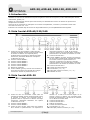
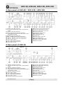
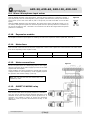
2. Vista frontal AXD-60/120/240
1. Control de tono de micrófonos: Actúa sobre las
entradas de MICRO. Girando el potenciómetro hacia
la derecha se obtiene una respuesta plana y
girándolo hacia la izquierda se atenúan las bajas
frecuencias, obteniendo fácilmente una óptima
ecualización de la voz.
2. Volumen entrada MICRO 1.
3. Volumen entrada MICRO 2.
4. Volumen entrada MICRO 3.
5. Volumen entrada MICRO 4.
6. Volumen entrada MICRO 5.
7. Módulo de expansión.
8. Control “BASS” (graves): Permite una variación de
nivel sobre la señal de las entradas AUX a bajas
frecuencias. Girando el potenciómetro a la
izquierda se atenúan en 10 dB. En la posición
central se obtiene una respuesta plana. Girando el
potenciómetro a la derecha se acentúan en 10 dB.
9. Volumen entrada AUX 1.
10. Control “TREBLE” (agudos): Permite una variación
de nivel sobre la señal de las entradas AUX a altas
frecuencias. Girando el potenciómetro a la
izquierda, se atenúan en 10 dB. En la posición
central se obtiene una respuesta plana. Girando el
potenciómetro a la derecha se acentúan en 10 dB.
11. Volumen entrada AUX 2.
12. Control de Volumen General.
13. Led indicador ( “0” / “I” ).
14. Interruptor puesta en marcha ( “0” / “I” ).
15. Indicador de nivel.
3. Vista frontal AXD-30
1. Control de tono de micrófonos. Actúa sobre las
entradas de MICRO. Girando el potenciómetro hacia
la derecha se obtiene una respuesta plana y
girándolo hacia la izquierda se atenúan las bajas
frecuencias, obteniendo fácilmente una óptima
ecualización de la voz.
2. Volumen entrada MICRO 1.
3. Volumen entrada MICRO 2.
4. Control de tono de AUX. Actúa sobre las entradas
AUX. Girando el potenciómetro a la izquierda se
atenúan en 10 dB las frecuencias bajas. En la
posición central se obtiene una respuesta plana.
Girando el potenciómetro a la derecha se acentúan
en 10 dB las frecuencias altas.
5. Volumen entrada AUX 1.
6. Volumen entrada AUX 2.
7. Módulo de expansión.
8. Control de Volumen General.
9. Led indicador (“0” / “I”).
10. Interruptor puesta en marcha (“0” / “I”).
Figura 1
Figura 2

AXD-30, AXD-60, AXD-120, AXD-240
AXD-30/60/120/240 v1.3
5
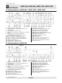
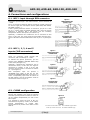
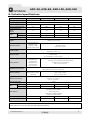
4. Vista posterior AXD-60 / AXD-120 / AXD-240
1. Entrada MICRO 1 conector DIN.
2. Señal de preaviso / alimentación phantom de la
entrada MIC.1.
3. Entrada MICRO 1 conector XLR .
4. Activación de preferencia de palabra de la entrada
MIC.2.
5. Configuración de la señal de preaviso /
alimentación phantom de la entrada MIC.2.
6. Entrada MICRO 2 conector XLR
7, 8, 9. Entradas y configuración MICRO 3.
10, 11, 12. Entradas y configuración MICRO 4.
13, 14, 15. Entradas y configuración MICRO 5.
16. Volumen entrada AUX 1.
17. Entrada AUX 1 (conectores RCA).
18. Entrada AUX 2 (conectores RCA).
19. Volumen entrada AUX 2.
20. Entrada emergencia (conector RJ45).
21. Salida de previo (conector XLR).
22. Salida de previo (conector RCA).
23. Entrada a la etapa de potencia.
24. Mezclador de las entradas de micrófono.
25. Módulo de expansión.
26. Salida de líneas de altavoces.
27. Fusible de red.
28. Red de 230 V.c.a.
29. Relé auxiliar de seguridad de avisos.
30. Conexión de la masa al chasis.
31. Entrada de alimentación por batería.
32. Toma de tierra.
5. Vista posterior AXD-30
1. Entrada MICRO 1 conector DIN
2. Señal de preaviso / alimentación phantom de la
entrada MIC.1.
3. Entrada MICRO 1 conector XLR.
4. Activación de preferencia de palabra de la entrada
MIC.2.
5. Configuración de la señal de preaviso /
alimentación phantom de la entrada MIC.2.
6. Entrada MICRO 2 conector XLR.
16. Volumen entrada AUX 1.
17. Entrada AUX 1 (conectores RCA).
18. Entrada AUX 2 (conectores RCA).
19. Volumen entrada AUX 2.
20. Entrada emergencia (conector RJ45).
21. Salida de previo (conector XLR).
22. Salida de previo (conector RCA).
23. Entrada a la etapa de potencia.
24. Mezclador de las entradas de micro.
25. Módulo de expansión.
26. Salida de líneas de altavoces.
27. Fusible de red.
28. Red de 230 V.c.a.
29. Relé auxiliar de seguridad de avisos.
30. Conexión de la masa al chasis.
31. Entrada de alimentación por batería.
32. Toma de tierra.
Figura 3
Figura 4

AXD-30, AXD-60, AXD-120, AXD-240
AXD-30/60/120/240 v1.3
6
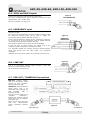
6. Conexiones y configuraciones
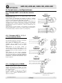
6.1. Entrada MIC 1 a través de conector
DIN
Entrada simétrica a través de un conector DIN de 180°, con una
sensibilidad de -60dB.
El pin número 4 proporciona una tensión de 24V.c.c. (máximo
100mA.) que puede ser utilizada para alimentar dispositivos de bajo
consumo (pupitres MEF-25DP, MEF-25DPG, MD-94R4...)
Dispone de un contacto de preferencia de palabra. Para activarlo es
necesario unir el pin núm. 5 al pin núm. 2 (masa). Con el dipswitch
de MIXER en OFF , al activar la preferencia de palabra, el MIC 1 tiene
prioridad sobre el resto de micrófonos y sobre las entradas AUX (ver
apartado 6.9).
Opcionalmente se puede acoplar a esta entrada un transformador
para línea balanceada; en este caso, la señal entraría por los pins 1 y
3 del conector DIN y la masa en el pin nº 2 (Ver figura 6).
6.2. Entradas MIC 1, 2, 3, 4
y 5 (conectores XLR)
Entradas MIC.1 y MIC.2 en AXD-30
Son entradas simétricas a través de conectores
XLR, con una sensibilidad de -60dB.
Para activar la preferencia de palabra es
necesario unir el contacto de la regleta
PRIORITY CONTROL INPUT a masa (Ver figura
10).
Opcionalmente se les puede acoplar un
transformador para línea balanceada; en este
caso, la señal se conecta a los contactos 2 y 3
del conector XLR y la masa al contacto nº 1 (Ver
figura 8).
Cada entrada de micro puede suministrar
alimentación de 24 V.c.c de tipo “PHANTOM”.
Para ello debe situarse el dipswitch PHANTOM
(ver figura 11) de la entrada correspondiente en
posición ON, y conectar el micrófono tal y como
indica la figura 9.
6.3. Configuración CHIME
Este dipswitch permite habilitar la señal de
preaviso. Dicha señal se activa al cerrar el
contacto de preferencia de palabra. Se puede
habilitar independientemente para cada una de
las entradas de Micro.
Es posible ajustar el nivel de la señal de
preaviso mediante el potenciómetro interno
VR301 en los modelos AXD-60/120/240 y
VR201 en el AXD-30.
Figura 5
Figura 6
Figura 7
Figura 8
Figura 9
Figura 10
Preaviso deshabilitado: OFF
Habilita preaviso: ON
OFF: Aliment. PHANTOM deshabilitada
ON: Habilita Aliment. PHANTOM
Habilita preaviso: ON
Figura 11

AXD-30, AXD-60, AXD-120, AXD-240
AXD-30/60/120/240 v1.3
7
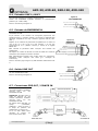
6.4. Entradas AUX1 y AUX2
Son entradas asimétricas mediante conectores RCA.
Tienen una sensibilidad ajustable mediante un potenciómetro
posterior (de -10dB a 0dB).
Para su conexión siga la figura 12.
6.5. Entrada de EMERGENCIA
Es una entrada asimétrica mediante conector RJ45, con una
sensibilidad de 0dB.
El pin número 3 del conector de emergencia proporciona una
tensión de 24V.c.c. (máximo 100mA.) que puede ser utilizada para
alimentar dispositivos de bajo consumo (pupitres MD-94, MD-
94R...).
Dispone de un contacto de preferencia de palabra que se activa al
unir el pin nº 6 con el pin nº 8 del conector, a la vez que
proporciona 24 V.c.c (máximo 100mA.) a través de la regleta
RELAY ACT.
Esta entrada es prioritaria sobre cualquier otra entrada del
amplificador.
No dispone de control de volumen. El nivel de salida de la señal de
emergencia será siempre a máximo volumen.
Está especialmente indicada para recibir avisos de emergencia,
prioritarios sobre cualquier otra señal (p.e. mensajes de
evacuación).
Para su conexión (siga la figura 13) debe utilizarse cable STP de Cat
5.
6.6. Salida LINE OUT
Es una salida de previo asimétrica mediante conector XLR macho,
con una sensibilidad de 0dB.
Para su conexión siga la figura 14.
6.7. Conexiones PRE-OUT / POWER IN
PRE-OUT: Salida de previo. Es
una salida asimétrica mediante
conector RCA, con una
sensibilidad de 0dB.
POWER-IN: Entrada hacia la
etapa de potencia. Es una
entrada asimétrica mediante
conector RCA, con una
sensibilidad de 0dB.
Se utilizan para intercalar un
equipo (ecualizador,
antilarsen...) entre el previo y
la etapa de potencia del
amplificador (ver figura 15).
Si no se usan deben tener
colocado el puente de
interconexión entre ellas.
Figura 15
Figura 14
Figura 13
Figura 12

AXD-30, AXD-60, AXD-120, AXD-240
AXD-30/60/120/240 v1.3
8
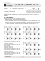
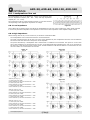
6.8. Salida de líneas de altavoces
La salida de la línea de altavoces se efectúa a través de un
transformador que dispone de salidas en baja impedancia (4Ω - 8Ω-
16Ω) y en alta impedancia (50 - 70 -100V.).
La conexión debe hacerse entre el terminal “0” y el que corresponda a
la impedancia o la tensión adecuada.
6.8.1. Baja impedancia
Se utilizará una de estas tres salidas cuando los altavoces no tengan transformador de línea y se escogerá de tal
forma que la impedancia de la línea de altavoces sea la misma que la impedancia del contacto de salida del
amplificador.
6.8.2. Alta impedancia
Al trabajar con las líneas de 50, 70 y 100V. es preciso recordar que:
- Los altavoces a conectar deben ir provistos de transformador de línea.
- La potencia total conectada será la suma de las potencias absorbidas por los altavoces y debe estar entre un 50%
por debajo y un 20% por encima de la potencia nominal del amplificador.
- La potencia absorbida por un altavoz con transformador está indicada en los terminales del mismo. Esta potencia
es en línea de 100V. Si se conecta el transformador a la línea de 70V., absorberá la mitad de la potencia indicada y
si se conecta a la línea de 50V. absorberá la cuarta parte. Un transformador de 30 W. absorberá 15 W. si se
conecta a la línea de 70V. y 7,5 W. si se conecta a la línea de 50V.
AXD-60 (Ver fig. 17)
A. Potencia total absorbida 60W.
Potencia absorbida por cada transformador de 10W.= 10W.
B. Potencia total absorbida 60W.
Potencia absorbida por cada transformador de 10W.= 5W.
C. Potencia total absorbida 60W.
Potencia absorbida por cada transformador de 10W.= 2,5W.
AXD-120 (Ver fig. 18)
A. Potencia total absorbida 120W.
Potencia absorbida por cada transformador de 20W.= 20W.
B. Potencia total absorbida 120W.
Potencia absorbida por cada transformador de 20W.= 10W.
C. Potencia total absorbida 120W.
Potencia absorbida por cada transformador de 20W.= 5W.
AXD-240 (Ver fig. 19)
A. Potencia total absorbida 240W.
Potencia absorbida por cada transformador de 40W.= 40W.
B. Potencia total absorbida 240W.
Potencia absorbida por cada transformador de 40W.= 20W.
C. Potencia total absorbida 240W.
Potencia absorbida por cada transformador de 40W.= 10W.
Figura 17
Figura 18
Figura 19
Figura 16

AXD-30, AXD-60, AXD-120, AXD-240
AXD-30/60/120/240 v1.3
9
6.9. Mixer: Mezclador de las entradas de micrófono
Situando el dipswitch MIXER en posición OFF, al activar la preferencia de palabra, la entrada MIC
1 tiene prioridad sobre el resto de entradas de MIC (2,3,4,5) y estas sobre las entradas AUX1 y 2
(en el caso de un AXD-30, el MIC 1 tiene preferencia sobre el MIC 2 y éste sobre las entradas
AUX).
Con el dipswitch MIXER en posición ON, se mezclan las señales de todas las entradas de micro (1
a 5), cortando la señal de las entradas AUX al activar la preferencia de palabra (en el caso de un
AXD-30, el MIC 1 y MIC 2 se mezclan y cortan la señal de AUX al activar la preferencia de palabra).
6.10. Modulo de expansión
El amplificador dispone de un espacio reservado para la colocación de módulos de expansión de la familia AXD (AXD-
MP3, AXD-TEL…).
6.11. Fusible de red
Se encuentra situado en el cajetín inferior de la base de alimentación. También hay un recambio en el mismo cajetín.
El valor del fusible varía en función del modelo de amplificador.
Modelo
AXD-30
AXD-60
AXD-120
AXD-240
Fusible de red
1 A
1,6 A
2,5 A
6,3 A
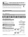
6.12. Conexión a la red
En la placa posterior dispone de una base macho CEE22
para la alimentación que permite conectarlo a la red
mediante el cable suministrado junto al amplificador.
Estos amplificadores salen de fábrica preparados para
trabajar con una tensión de red de 230 V.c.a. Bajo pedido
pueden suministrarse preparados para ir alimentados a
otro voltaje (115 V.c.a.)
6.13. Conexión relé SURETY
PAGING
Conmuta cuando se activa la preferencia de palabra.
Se utilizan para activar elementos externos que tengan
que ser activados al mismo tiempo que actúa la
preferencia de palabra. El ejemplo de la figura 21
representa el esquema de conexión para disponer de
seguridad de avisos en las atenuadoras.
Figura 20
Atención: Este aparato no puede estar expuesto al
agua o a salpicaduras
Figura 21

AXD-30, AXD-60, AXD-120, AXD-240
AXD-30/60/120/240 v1.3
10
6.14. Conexión de la masa al chasis
En toda instalación es muy importante que haya un
solo punto de conexión entre la masa de la señal y
la toma de tierra de la red. Los aparatos OPTIMUS
disponen de conector del tipo “shucko”, lo que
permite conectar el chasis con el tierra de la red.
Si la instalación está compuesta por más de un
aparato, probablemente tendrán los chasis unidos,
bien mediante el terminal de tierra de la conexión a
la red, o bien porque estarán montados en un
armario metálico.
Si las masas están unidas por los circuitos de señal,
es aconsejable quitar el puente entre la masa y el
chasis de todos los aparatos excepto uno, evitando
así ruidos provocados por los bucles del circuito de
masas (ver figura 22).
6.15. Alimentación por batería
Esta alimentación permite el uso de estos aparatos en instalaciones de seguridad, conectando una batería de 24V.c.c.
El interruptor “0” / “I” no interrumpe la alimentación de batería.
El fusible de batería a es interno, y su valor varía en función del modelo.
Modelo
AXD-30
AXD-60
AXD-120
AXD-240
Fusible de batería
6,3 A
8 A
15 A
20 A
7. Protecciones térmicas
Los modelos AXD-60, AXD-120 y AXD-240 disponen de protecciones de térmicas que limitan la temperatura interna a
95 C.
Los AXD-120 y AXD-240 disponen además de ventilación forzada mediante un ventilador interno.
Figura 22

AXD-30, AXD-60, AXD-120, AXD-240
AXD-30/60/120/240 v1.3
11
8. Características técnicas
AXD-30
AXD-60
AXD-120
AXD-240
Alimentación Red
230 V CA / 24 V CC, 50-60 Hz
Alimentación Batería
24 V CC
Consumo vacío (VA)
11,5
16
18,4
20,7
Consumo plena carga (VA)
57,5
128,8
276
529
Intensidad absorbida de la
batería
(28,8 V)
2 A
4 A
8 A
16 A
Potencia de
salida
RMS
30 W
60 W
120 W
240 W
IHF
40 W
98 W
175 W
350 W
Salidas altavoces
100, 70, 50 V ó 4,8,16 Ohm
Salidas
-Pre Out / Power In : 775 mV (0 dB)
-Salida de previo LINE OUT 775 mV (0 dB)
Entradas Micrófono
2 Simétricas XLR (una
duplicada a DIN).
Sensibilidad: -60dB
Ambas con control de
prioridad
5 Simétricas XLR (una duplicada a DIN)
Sensibilidad: -60dB
Todas con control de prioridad
Entradas Auxiliar
2 asimétricas conector RCA
Sensibilidad de 150mV a 1V
Entrada emergencia
1 asimétrica conector RJ45. Sensibilidad 0dB
No resulta afectada por ningún control frontal
Función de prioridad
-Emergencia sobre
micrófonos y auxiliares
-Micrófonos sobre
auxiliares
-MIC1 sobre MIC2
-Emergencia sobre micros y auxiliares
-Micros sobre auxiliares
-Micro 1 sobre micros 2 a 5
Controles de tono Micro
Control de tono
Respuesta plana con el control al máximo
Controles de tono AUX
Control de tono
Respuesta plana con el
control al máximo
Baxandall
Graves:±10 dB a 100Hz
Agudos: ±10 dB a 10kHz
Respuesta en frecuencia
Aux: 50 - 18000 Hz
Emergencia: 50 -18000 Hz
Mic: 60 - 10000 Hz
THD + N unidad de potencia
<0,75%
Relación
Señal/ruido
Mic.
-65 dB
-65 dB
-66 dB
-65 dB
Aux.
-73 dB
-72 dB
-70 dB
-70 dB
Otras prestaciones
- En cada entrada Mic, dipswitch de configuración de Gong ON/OFF
y alimentación Phantom ON/OFF
- Relé de seguridad de avisos
- Dipswitch externo de Mixer ON/OFF
- Salida 24V en DIN y RJ45
Dimensiones (mm)
430 x 89 x 250 (2u)
430 x 89 x 280 (2u)
430 x 89 x 290 (2u)
430 x 89 x 380 (2u)
Peso
6 Kg
7,5 Kg
9 Kg
13 Kg
ATENCIÓN. Este es un equipo de Clase A. En un ambiente doméstico podría llegar a causar radio interferencias.
En este caso el usuario debería tomar las medidas adecuadas.

AXD-30, AXD-60, AXD-120, AXD-240
AXD-30/60/120/240 v1.3
12
9. Condiciones de garantía
1. CERTIFICADO DE GARANTÍA
1. La empresa OPTIMUS S.A. garantiza que sus productos se encuentran libres
de defectos en materiales y de mano de obra en el momento de su entrega
original al comprador.
2. La empresa OPTIMUS S.A. concede a sus productos, conforme a las
condiciones aquí descritas, una garantía de dos (2) años a partir de la fecha de
adquisición del producto por el comprador. Si, dentro de este plazo de garantía,
se producen defectos que no sean debidos a razones mencionadas bajo el punto
2, la empresa OPTIMUS S.A. reemplazará o reparará el aparato utilizando piezas
de recambio equivalentes, nuevas o reconstruidas, según criterio propio. Si se
aplican piezas de recambio que constituyen una mejora del aparato, la empresa
OPTIMUS S.A. se reserva el derecho de cargar el coste adicional de estos
componentes al cliente.
3. No se concederán prestaciones de garantía distintas a las citadas.
4. Para la utilización de los derechos de garantía será requisito indispensable
presentar la factura de compra original o el certificado de garantía.
2. DISPOSICIONES DE GARANTÍA
1. Si el producto tuviera que ser modificado o adaptado para cumplir con los
requisitos locales en cuanto a técnica o seguridad, si no se trata del país para el
cual el producto fue concebido y fabricado originalmente, ello no se considera
como defecto de material o de fabricación. Por lo demás, la garantía no
comprende la realización de estas modificaciones o adaptaciones,
independientemente de si éstas hayan sido ejecutadas debidamente o no.
OPTIMUS S.A. tampoco asumirá costes en el marco de la garantía por este tipo
de modificaciones.
2. La garantía no dará derecho a inspección o mantenimiento gratuito o
reparación del aparato, particularmente si los defectos son debidos a uso
inapropiado. Los derechos de garantía tampoco abarcan defectos en piezas de
desgaste que sean debidos a un desgaste normal. Piezas de desgaste son, en
particular, potenciómetros, interruptores/teclas, y piezas similares.
3. La garantía no abarca los defectos en el equipo causados por:
Abuso o uso incorrecto del aparato para fines distintos a los previstos, en
incumplimiento de las instrucciones de servicio y de mantenimiento
especificadas en el Manual y/o Instrucciones Técnicas del equipo.
Conexión o uso del producto de una manera que no corresponda a los
requisitos técnicos o de seguridad del país en el cual se utiliza el aparato.
Instalación en condiciones distintas a los indicados en el Manual y/o
Instrucciones Técnicas.
Deficiencia o interrupciones tensión eléctrica o defectos de instalación que
impliquen uso en condiciones anormales.
Daños ocasionados por otros equipos interconectados al producto.
El uso o instalación de Software (programas), interfaces, partes o
suministros no proporcionados y/o autorizados por OPTIMUS S.A.
La no utilización de los embalajes originales para su transporte.
Daños causados por fuerza mayor u otras causas no imputables a OPTIMUS
S.A.
4. No están cubiertos por esta garantía los siguientes elementos:
Todas las superficies de plástico y todas las piezas expuestas al exterior que
hayan sido rayadas o dañadas debido al uso normal o anormal.
Las roturas, golpes, daños por caídas o ralladuras causadas por traslados de
cualquier naturaleza.
Defectos de daños derivados de pruebas, uso, mantenimiento, instalación y
ajustes inapropiados, o derivados de cualquier alteración o modificación de
cualquier tipo no realizada por en Servicio Autorizado por OPTIMUS S.A. en
cumplimiento de esta garantía.
Los daños personales o a la propiedad que pudieran causar el uso indebido
del equipo, incluyendo la falta de mantenimiento.
5. La garantía carecerá de validez cuando se observe:
Enmiendas o tachaduras en los datos del certificado de garantía o factura
de compra.
Falta de factura original o falta de fecha en la misma.
Falta de número de serie o lote en el equipo.
6 En el caso de ordenadores P.C., la garantía no cubrirá la eliminación de virus
informáticos, restauración de programas por este motivo o la reinstalación del
disco provocada por el borrado del mismo.
7. Los derechos de garantía se anulan si el producto ha sido reparado o
abierto por un personal no autorizado OPTIMUS S.A. o por el propio cliente.
8. Si la empresa OPTIMUS S.A. estableciera al comprador del aparato que los
daños presentados no dan derecho a la reclamación de la garantía, los costes de
las prestaciones de revisión por parte de la empresa OPTIMUS S.A. correrán a
cargo del cliente.
9. Los productos sin derechos de garantía sólo se repararán contra pago de los
gastos por el cliente. En caso de ausencia de derechos de garantía, OPTIMUS S.A.
informará al cliente al respecto. Si, en un plazo de 6 semanas a partir de esta
comunicación, no recibimos ninguna orden de reparación escrita confirmando la
aceptación de los gastos, OPTIMUS S.A. devolverá el aparato en cuestión al
cliente. En este caso, los gastos de transporte y embalaje se facturarán por
separado y se cobrarán contra reembolso. En caso de expedición de una orden
de reparación, confirmando la asunción de los gastos, los gastos de transporte y
de embalaje se facturarán adicionalmente, igualmente por separado.
10. En caso de necesidad de traslado al Centro de Servicio Autorizado, el
transporte será realizado por el responsable de la garantía, y serán a su cargo los
gastos de flete y seguro.
11. En caso de falla, OPTIMUS S.A. asegura al comprador la reparación y/o
reposición de partes para su correcto funcionamiento en un plazo no mayor a 30
días. No obstante, se deja aclarado que el plazo usual no supera los 30 días.
12. Todas las piezas o productos sustituidos al amparo de los servicios en
garantía pasarán a ser propiedad de OPTIMUS S.A.
3. TRANSFERENCIA DE LA GARANTÍA
La garantía se concede únicamente para el comprador original (cliente principal)
y es intransferible. Con excepción de la empresa OPTIMUS S.A., ningún tercero
(comerciantes, etc.) está autorizado a conceder garantía adicionales en nombre
de la empresa OPTIMUS S.A.
4. RECLAMACIONES POR DAÑOS Y PERJUICIOS
En caso de que OPTIMUS S.A. no pueda proporcionar un servicio de garantía
adecuado, el comprador no tendrá ningún derecho a reclamar indemnización
alguna por daños y perjuicios consecuentes. La responsabilidad de la empresa
OPTIMUS S.A. se limita en todo caso al precio de facturación del producto.
5. RELACIÓN CON OTROS DERECHOS DE GARANTÍA Y CON EL DERECHO
NACIONAL
1. Mediante esta garantía no se afecta a los derechos del comprador frente al
vendedor deducidos del contrato de compraventa concluido.
2. Las presentes condiciones de garantía de la empresa OPTIMUS S.A. son válidas
siempre que no contradigan el derecho nacional correspondiente en relación con
las disposiciones de garantía.
3. OPTIMUS S.A. asegura que este producto cumple con las normas de seguridad
vigentes en el país.
ESTA DECLARACIÓN DE GARANTÍA LIMITADA ES LA GARANTÍA EXCLUSIVA
OFRECIDA POR OPTIMUS S.A. SE EXCLUYE TODA OTRA GARANTÍA EXPLÍCITA O
IMPLÍCITA, INCLUIDAS LAS GARANTÍAS DE COMERCIALIDAD Y APTITUD A UN FIN
DETERMINADO. (EXCEPTO CUANDO DICHAS GARANTÍAS SEAN REQUERIDAS POR
UNA LEY APLICABLE). NINGUNA GARANTÍA, YA SEA EXPLÍCITA O IMPLÍCITA, SE
APLICARÁ TRAS LA FINALIZACIÓN DEL PERIODO DE GARANTÍA.
OPTIMUS S.A.
Servicio Post Venta
C/ Barcelona 101
17003 - GIRONA
Tel. 902 151 96 / 972 203 300
Fax. 972 21 84 13


AXD-30, AXD-60, AXD-120, AXD-240
AXD-30/60/120/240 v1.3
3
Contents
1. Introduction .......................................................................................................................................... 4
2. Front view of AXD-60/120/240 ............................................................................................................. 4
3. Front view of AXD-30............................................................................................................................. 4
4. Rear panel of AXD-60 / AXD-120 / AXD-240 ......................................................................................... 5
5. Rear panel of AXD-30 ............................................................................................................................ 5
6. Connections and configurations ............................................................................................................. 6
6.1. MIC 1 input through DIN connector ............................................................................................... 6
6.2. MIC 1, 2, 3, 4 and 5 inputs (XLR connectors) .................................................................................. 6
6.3. CHIME configuration .................................................................................................................... 6
6.4. AUX1 and AUX2 inputs ................................................................................................................ 7
6.5. EMERGENCY input ....................................................................................................................... 7
6.6. LINE OUT ................................................................................................................................... 7
6.7. PRE-OUT / POWER IN Connections ................................................................................................ 7
6.8. Loudspeakers line out .................................................................................................................. 8
6.9. Mixer: Microphone input mixer ..................................................................................................... 9
6.10. Expansion module ................................................................................................................... 9
6.11. Mains fuse ............................................................................................................................. 9
6.12. Mains connections ................................................................................................................... 9
6.13. SURETY PAGING relay connection ............................................................................................. 9
6.14. Earth to chassis connection .................................................................................................... 10
6.15. Battery power supply ............................................................................................................ 10
7. Thermal protection .............................................................................................................................. 10
8. Technical specifications ....................................................................................................................... 11
9. Guarantee ............................................................................................................................................ 12

AXD-30, AXD-60, AXD-120, AXD-240
AXD-30/60/120/240 v1.3
4
1. Introduction
These four models are integrated amplifiers of 30, 60, 120 and 240W respectively, designed for use in all kinds of
fixed public address systems that broadcast emergency announcements and background music for offices, restaurants,
churches, etc.
The amplifiers have thermal protection to avoid failures due to overheating. The protection system is reinforced by
fuses.
As a general rule, it is recommended that no operation should be performed on the inside of the amplifier, the
connectors or the terminals, when the amplifier is connected to the AC or DC supply.
These amplifiers have been designed to meet Electrical Safety and Electromagnetic Compatibility standards.
2. Front view of AXD-60/120/240
1. Microphone tone control: Acts on the MICRO
inputs. By turning the potentiometer towards the
right, a flat response is obtained; by turning it
towards the left, low frequencies are decreased,
and so it is easy to obtain optimum voice
equalization.
2. MICRO 1 input volume.
3. MICRO 2 input volume.
4. MICRO 3 input volume.
5. MICRO 4 input volume.
6. MICRO 5 input volume.
7. Expansion module.
8. BASS control: Varies the signal level of the AUX
inputs at low frequencies. By turning the
potentiometer to the left, the bass is decreased by
10 dB. In the central position a flat response is
obtained. By turning the potentiometer to the right,
the bass is increased by 10 dB.
9. AUX 1 input volume.
10. TREBLE control: Varies the signal level of the AUX
inputs at high frequencies. By turning the
potentiometer to the left, the treble is decreased by
10 dB. In the central position a flat response is
obtained. By turning the potentiometer to the right,
the treble is increased by 10 dB.
11. AUX 2 input volume.
12. General Volume Control.
13. LED indicator ( “0” / “I” ).
14. On/Off switch ( “0” / “I” ).
15. Level indicator.
3. Front view of AXD-30
1. Microphone tone control. Acts on the MICRO
inputs. By turning the potentiometer towards the
right, a flat response is obtained; by turning it
towards the left, low frequencies are decreased,
and so it is easy to obtain optimum voice
equalisation.
2. MICRO 1 input volume.
3. MICRO 2 input volume.
4. AUX tone control. Acts on the AUX inputs. By
turning the potentiometer to the left, low
frequencies are decreased by 10 dB. In the central
position a flat response is obtained. By turning the
potentiometer to the right, high frequencies are
increased by 10 dB.
5. AUX 1 input volume.
6. AUX 2 input volume.
7. Expansion module.
8. General Volume Control.
9. LED indicator (“0” / “I”).
10. On/Off switch (“0” / “I”).
Figure 1
Figure 2

AXD-30, AXD-60, AXD-120, AXD-240
AXD-30/60/120/240 v1.3
5
4. Rear panel of AXD-60 / AXD-120 / AXD-240
1. MICRO 1 input DIN connector.
2. Pre-announcement signal / MIC.1 input phantom
supply.
3. MICRO 1 input XLR connector.
4. MIC.2 input speech preference activation.
5. Configuration of pre-announcement signal / MIC.2
input phantom supply.
6. MICRO 2 input XLR connector.
7, 8, 9. MICRO 3 inputs and configuration.
10, 11, 12. MICRO 4 inputs and configuration.
13, 14, 15. MICRO 5 inputs and configuration.
16. AUX 1 input volume.
17. AUX 1 input (RCA connectors).
18. AUX 2 input (RCA connectors).
19. AUX 2 input volume.
20. Emergency input (RJ45 connector).
21. Preview output (XLR connector).
22. Preview output (RCA connector).
23. Power phase input.
24. Microphone inputs mixer.
25. Expansion module.
26. Loudspeakers line out.
27. Mains fuse.
28. Mains supply of 230V AC.
29. Surety Paging relay.
30. Earth to chassis connection.
31. Battery power supply input.
32. Earth connection.
5. Rear panel of AXD-30
1. MICRO 1 input DIN connector.
2. Pre-announcement signal / MIC.1 input phantom
supply.
3. MICRO 1 input XLR connector.
4. MIC.2 input speech preference activation.
5. Configuration of pre-announcement signal / MIC.2
input phantom supply.
6. MICRO 2 input XLR connector.
16. AUX 1 input volume.
17. AUX 1 input (RCA connectors).
18. AUX 2 input (RCA connectors).
19. AUX 2 input volume.
20. Emergency input (RJ45 connector).
21. Preview output (XLR connector).
22. Preview output (RCA connector).
23. Power phase input.
24. Microphone inputs mixer.
25. Expansion module.
26. Loudspeakers line out.
27. Mains fuse.
28. Mains supply of 230V AC.
29. Surety Paging relay.
30. Earth to chassis connection.
31. Battery power supply input.
32. Earth connection.
Figure 3
Figure 4

AXD-30, AXD-60, AXD-120, AXD-240
AXD-30/60/120/240 v1.3
6
6. Connections and configurations
6.1. MIC 1 input through DIN connector
Symmetric input through a 180° DIN connector, with a sensitivity of
– 60dB.
Pin no. 4 provides a voltage of 24V DC (maximum 100mA) which can
be used to supply low-consumption devices (MEF-25DP, MEF-25DPG,
MD-94R4 consoles....).
It has a speech preference contact. To activate it, join pin no. 5 with
pin no. 2 (earth). With the MIXER dipswitch OFF, when the speech
preference is activated, MIC 1 has priority over the remaining
microphones and the AUX inputs (see section 6.9).
Optionally, a balanced line transformer can be connected to this
input; in this case, the signal would be transmitted through pins 1
and 3 of the DIN connector DIN and the earth in pin no. 2 (See Figure
6).
6.2. MIC 1, 2, 3, 4 and 5
inputs (XLR connectors)
MIC.1 and MIC.2 inputs on AXD-30
These are symmetric inputs through XLR
connectors, with a sensitivity of – 60dB.
To activate the speech preference, join the
contact of the PRIORITY CONTROL INPUT strip
to the earth (See Figure 10).
Optionally, a balanced line transformer can be
connected to them; in this case, the signal is
connected to contacts 2 and 3 of the XLR
connector and the earth is connected to contact
no. 1 (See Figure 8).
Each microphone input can provide a
“PHANTOM”-type supply of 24V DC. For this
purpose the PHANTOM dipswitch (see Figure 11)
of the corresponding input must be moved to
the ON position, and the microphone must be
connected as shown in Figure 9.
6.3. CHIME configuration
The pre-announcement signal is enabled
through this dipswitch. This signal is activated
when the speech preference contact is closed. It
can be enabled independently for each of the
Micro inputs.
It is possible to adjust the level of the pre-
announcement signal by means of the VR301
internal potentiometer on models AXD-
60/120/240 and by means of the VR201 on the
AXD-30.
Figure 5
Figure 6
Figure 7
Pre-announcement disabled: OFF
Enable pre-announcement: ON
OFF: PHANTOM supply disabled
ON: Enable PHANTOM supply
Figure 11
Figure 8
Figure 9
Figure 10

AXD-30, AXD-60, AXD-120, AXD-240
AXD-30/60/120/240 v1.3
7
6.4. AUX1 and AUX2 inputs
These are asymmetric inputs through RCA connectors.
They have a sensitivity that can be adjusted by means of a rear
potentiometer (from -10dB to 0dB)
For their connection, see Figure 12.
6.5. EMERGENCY input
This is an asymmetric input through a RJ45 connector, with a
sensitivity of 0dB.
Pin number 3 of the emergency connector supplies a voltage of 24V
DC (maximum 100mA) which can be used to supply low
consumption devices (MD-94, MD-94R consoles...)
It has a speech preference contact which is activated by joining pin
no. 6 with pin no. 8 of the connector, while it supplies 24V DC
(maximum 100mA) through the RELAY ACT strip.
This input has priority over any other input of the amplifier.
It does not have a volume control. The output level of the
emergency signal will always be at maximum volume.
It is especially suitable for receiving emergency announcements,
which take priority over any other signal (e.g. evacuation
messages).
Cable STP of Cat 5 must be used for its connection (see Figure 13).
6.6. LINE OUT
This is an asymmetric preview output through a male XLR
connector, with a sensitivity of 0dB.
For its connection, see Figure 14.
6.7. PRE-OUT / POWER IN Connections
PRE-OUT: Preview output.
This is an asymmetric output
through an RCA connector,
with a sensitivity of 0dB.
POWER-IN: Input towards the
power phase. This is an
asymmetric input through an
RCA connector, with a
sensitivity of 0dB.
They are used to install a unit
(equaliser, antilarsen...)
between the preview and the
power phase of the amplifier
(see Figure 15).
If they are not used, they must
have the interconnection
jumper positioned between
them.
Figure 15
Figure 13
Figure 12
Figure 14

AXD-30, AXD-60, AXD-120, AXD-240
AXD-30/60/120/240 v1.3
8
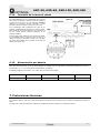
6.8. Loudspeakers line out
The loudspeakers line out is effected by means of a transformer that
has low impedance outputs (4Ω – 8Ω – 16Ω) and high impedance
outputs (50 – 70 – 100V).
The connection must be made between terminal “0” and the terminal
corresponding to the appropriate impedance or voltage.
6.8.1. Low impedance
One of these three outputs will be used when the loudspeakers do not have a line transformer, and it will be selected
in such a way that the loudspeaker line impedance is the same as the impedance of the amplifier output contact
6.8.2. High impedance
When working with the 50, 70 and 100V lines, it should be remembered that:
- The loudspeakers to be connected must have a line transformer.
- The total connected power will be the sum of the power absorbed by the loudspeakers and this must be between
50% below and 20% above the rated power of the amplifier.
- The power absorbed by a loudspeaker with a transformer is indicated on its terminals. This power is on the 100V
line. If the transformer is connected to the 70V line, it will absorb half the indicated power, and if it is connected to
the 50V line, it will absorb a quarter of this power. A 30W transformer will absorb 15W if it is connected to the 70V
line and 7.5W if it is connected to the 50V line.
AXD-60 (See Fig. 17)
A. Total input power 60W.
Power absorbed by each 10W transformer = 10W.
B. Total input power 60W.
Power absorbed by each 10W transformer = 5W.
C. Total input power 60W.
Power absorbed by each 10W transformer = 2.5W.
AXD-120 (See Fig. 18)
A. Total input power 120W.
Power absorbed by each 20W transformer = 20W.
B. Total input power 120W.
Power absorbed by each 20W transformer = 10W.
C. Total input power 120W.
Power absorbed by each 20W transformer = 5W.
AXD-240 (See Fig. 19)
A. Total input power 240W.
Power absorbed by each 40W transformer = 40W.
B. Total input power 240W.
Power absorbed by each 40W transformer = 20W.
C. Total input power 240W.
Power absorbed by each 40W transformer = 10W.
Figure 17
Figure 18
Figure 19
Figure 16

AXD-30, AXD-60, AXD-120, AXD-240
AXD-30/60/120/240 v1.3
9
6.9. Mixer: Microphone input mixer
With the MIXER dipswitch in the OFF position, when the speech preference is activated, the MIC 1
input has priority over the remaining MIC (2,3,4,5) inputs, and these have priority over the AUX1
and 2 inputs (in the case of the AXD-30, MIC 1 has priority over MIC 2 and MIC 2 over the AUX
inputs).
With the MIXER dipswitch in the ON position, the signals from all the microphone inputs (1 to 5)
are mixed, cutting off the signal from the AUX inputs when the speech preference is activated (in
the case of the AXD-30, MIC 1 and MIC 2 are mixed and cut off the AUX signal when the speech
preference is activated).
6.10. Expansion module
The amplifier includes a special place for installing the AXD series expansion modules (AXD-MP3, AXD-TEL…).
6.11. Mains fuse
This is located in the lower box of the power supply base. There is also a spare fuse in the same box. The value of the
fuse varies depending on the amplifier model.
Model
AXD-30
AXD-60
AXD-120
AXD-240
Mains fuse
1 A
1.6 A
2.5 A
6.3 A
6.12. Mains connections
On the rear panel there is a CEE22 plug base for the supply,
allowing connection to the mains supply by means of the cable
supplied with the amplifier.
These amplifiers are factory-prepared to operate with a mains
voltage of 230V AC. On request they can be supplied prepared
for operation with another voltage (115V CA).
6.13. SURETY PAGING relay
connection
This connects when when the speech preference is activated.
They are used to activate external elements that have to be
activated at the same time that the speech preference is in
operation. The example in Figure 21 shows the connection
diagram in order to provide announcement security in the
attenuators.
Figure 20
N.B.: This unit must not come into contact with or be
splashed by water.
Figure 21

AXD-30, AXD-60, AXD-120, AXD-240
AXD-30/60/120/240 v1.3
10
6.14. Earth to chassis connection
In all installations it is very important that there is
one single point of connection between the signal
earth connection and the mains supply earth
contact. The OPTIMUS units have a “shucko”-type
connector, which enables the chassis to be
connected to the mains earth connection.
If the installation comprises more than one
equipment unit, their chassis will probably be
joined, either by means of the earth terminal of the
mains connection, or because they will be fitted in a
metal cabinet.
If the earth connections are joined by the signal
circuits, it is advisable to remove the jumper
between the earth connection and the chassis from
all the units except one, thereby avoiding noises
caused by the loops of the earth connections circuit
(see Figure 22).
6.15. Battery power supply
This supply allows these units to be used in security installations, connecting a 24V DC battery.
The “0” / “I” switch does not interrupt the battery power supply.
The battery fuse is internal, and its value varies according to the model.
Model
AXD-30
AXD-60
AXD-120
AXD-240
Battery fuse
6.3 A
8 A
15 A
20 A
7. Thermal protection
The AXD-60, AXD-120 and AXD-240 models have thermal protection which limits the internal temperature to 95°C.
The AXD-120 and AXD-240 also have forced ventilation by means of an internal ventilator
Figure 22

AXD-30, AXD-60, AXD-120, AXD-240
AXD-30/60/120/240 v1.3
11
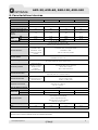
8. Technical specifications
AXD-30
AXD-60
AXD-120
AXD-240
Mains Supply
230 V CA / 24 V CC, 50-60 Hz
Battery Supply
24 V CC
Empty consumption (VA)
11.5
16
18.4
20.7
Full load consumption (VA)
57.5
128.8
276
529
Current intake of the
battery
(28,8 V)
2 A
4 A
8 A
16 A
Output
power
RMS
30 W
60 W
120 W
240 W
IHF
40 W
98 W
175 W
350 W
Loudspeaker outputs
100, 70, 50 V or 4,8,16 Ohm
Outputs
-Pre Out / Power In : 775 mV (0 dB)
- LINE OUT 775 mV (0 dB)
Microphone Inputs
2 Symmetric XLR (one
duplicated at DIN).
Sensitivity: -60dB
Both with priority control
5 Symmetric XLR (one duplicated at DIN).
Sensitivity: -60dB
All with priority control
Auxiliary Inputs
2 asymmetric RCA connector.
Sensitivity of 150mV to 1V
Emergency input
1 asymmetric RJ45 connector.
Sensitivity 0dB.
It is not affected by any front control.
Priority function
-Emergency over
microphones and
auxiliary inputs
-Microphones over
auxiliary inputs
-MIC 1 over MIC 2
-Emergency over microphones and auxiliary inputs
-Microphones over auxiliary inputs
-Micro 1 over micros 2 to 5
Microphone tone controls
Tone control.
Flat response with the control at maximum
AUX tone controls
Tone control. Flat
response with the control
at maximum
Baxandall
Bass:±10 dB a 100Hz
Treble: ±10 dB a 10kHz
Response in frequency
Aux: 50 - 18000 Hz
Emergency: 50 -18000 Hz
Mic: 60 - 10000 Hz
THD + N power unit
<0.75%
Signal/noise
ratio
Mic.
-65 dB
-65 dB
-66 dB
-65 dB
Aux.
-73 dB
-72 dB
-70 dB
-70 dB
Other features
- At each Mic input, Gong configuration dipswitch ON/OFF
and Phantom supply ON/OFF
- Surety paging relay
- Mixer external dipswitch ON/OFF
- Output 24V in DIN and RJ45
Dimensions (mm)
430 x 89 x 250 (2u)
430 x 89 x 280 (2u)
430 x 89 x 290 (2u)
430 x 89 x 380 (2u)
Weight
6 Kg
7.5 Kg
9 Kg
13 Kg
WARNING. This is a Class A product. In a domestic environment this product may cause radio interference in
wich case the user may be required to take adequate measures.

AXD-30, AXD-60, AXD-120, AXD-240
AXD-30/60/120/240 v1.3
12
9. Guarantee
1. GUARANTEE CERTIFICATE
1. OPTIMUS S.A. guarantees that its products are free from material and
manufacturing defects when they are first delivered to the purchaser.
2. In accordance with the conditions outlined here, OPTIMUS S.A. guarantees
its products for two (2) years from the date on which the purchaser acquires the
product. If, within this guarantee period, defects appear which are not due to
factors outlined in section 2, OPTIMUS S.A. shall replace or repair the unit using
equivalent, new or reconstructed replacement parts, as it deems fit. If
replacement parts are applied which improve the unit, OPTIMUS S.A. reserves
the right to charge the client for the additional cost of these components.
3. No guarantee benefits shall be provided other than those cited here.
4. In order to claim the guarantee rights, it shall be an essential requirement
to present the original purchase invoice or the guarantee certificate.
2. GUARANTEE PROVISIONS
1. In the event that the product had to be modified or adapted to comply with
local requirements concerning technical specifications or safety, and if the
country in question is not the country for which the product was originally
designed and manufactured, defects are not considered to be material or
manufacturing defects. Furthermore, the guarantee does not cover the
execution of these modifications or adaptations, regardless of whether or not
they have been carried out correctly.
Nor shall OPTIMUS S.A. be responsible for any costs under this guarantee for
these types of modifications.
2. The guarantee shall not entitle the purchaser to inspection or free
maintenance or repair of the unit, particularly if the defects are due to
inappropriate use. Nor do the guarantee rights cover defects in wearing parts
that become worn as a result of normal wear and tear. Wearing parts are, in
particular, potentiometers, switches/keys, and similar parts.
3. The guarantee does not cover defects in the equipment unit caused by:
Abuse or incorrect use of the unit for purposes other than those for which it
is intended, in non-compliance with the service and maintenance
instructions specified in the Manual and/or Technical Instructions for the
unit.
Connection or use of the product in a manner that does not correspond to
the technical or safety requirements of the country in which the unit is
used.
Installation in conditions other than those indicated in the Manual and/or
Technical Instructions.
Deficiency or interruptions in the electricity supply or installation defects
which imply use in abnormal conditions.
Damage caused by other equipment units that are connected to the
product.
The use or installation of Software (programmes), interfaces, parts or
supplies not provided and/or not authorised by OPTIMUS S.A.
Failure to use the original packaging for transportation.
Damage caused by force majeure or other causes not attributable to
OPTIMUS S.A.
4. The following elements are not covered by this guarantee:
All plastic surfaces and all parts exposed to outdoor conditions which have
been scratched or damaged as a result of normal or abnormal use.
Breakages, knocks, damage due to a fall or scratches caused by moving the
unit in any way.
Damage caused by tests, use, maintenance, installation or inappropriate
adjustments, or as a result of any alteration or modification of any kind not
carried out by a Service Authorised by OPTIMUS S.A. in compliance with this
guarantee.
Damage to persons or property that might be caused by the improper use
of the equipment, including lack of maintenance.
5. The guarantee shall not be valid whenever the following is observed:
Amendments or corrections made to the details of the guarantee certificate
or purchase invoice.
Failure to produce the original invoice or the absence of a date on this.
Absence of the serial or batch number on the equipment.
6. In the case of personal computers, the guarantee will not cover the
elimination of computer viruses, the restoration of programmes damaged by
these or the reinstallation of the disk following its deletion.
7. The rights of this guarantee are invalidated if the product has been repaired
or opened by staff unauthorised by OPTIMUS S.A. or by the client himself.
8. If OPTIMUS S.A. were to establish before the client that the damage
affecting the unit does not entitle a claim to be made under the guarantee, the
costs of checking the equipment incurred by OPTIMUS S.A. shall be borne by the
client.
9. Products not covered by the guarantee shall only be repaired once payment
has been effected by the client. In the event that the guarantee rights do not
apply, OPTIMUS S.A. shall duly inform the client. If, within a period of 6 weeks
from this communication, no written repair order is received from the client
confirming acceptance of the costs, OPTIMUS S.A. shall return the unit in
question to the client. In this case, the transport and packaging costs shall be
invoiced separately and payment shall be made on delivery. In the event that a
repair order is sent by the client, confirming that he assumes the costs of repair,
the transport and packaging costs shall be invoiced additionally, and also
separately.
10. If the equipment needs to be transferred to the Authorised Service Centre,
transportation shall be effected by the responsible party according to the
guarantee, who will also bear the freight and insurance costs.
11. In the event of a defect, OPTIMUS S.A. guarantees that the repair and/or
replacement of parts so that the unit operates correctly will be made within a
period of no more than 30 days. Nevertheless, OPTIMUS S.A. would like to clarify
that the normal period does not exceed 30 days.
12. All parts or products replaced as part of the guarantee services shall
become the property of OPTIMUS S.A.
3. TRANSFER OF GUARANTEE
The guarantee is solely awarded to the original purchaser (principal client) and is
not transferable. With the exception of OPTIMUS S.A., no third party (dealers,
etc.) is authorised to award additional guarantees on behalf of OPTIMUS S.A
4. CLAIMS FOR DAMAGE
In the event that OPTIMUS S.A. cannot provide a suitable guarantee
service, the purchaser shall not be entitled to claim any indemnity for
damages arising. The responsibility held by OPTIMUS S.A. is limited in all
cases to the invoicing price of the product.
5. RELATION WITH OTHER GUARANTEE RIGHTS AND NATIONAL LAW
1. This guarantee does not affect the rights of the purchaser with respect to the
vendor arising from the contract of sale accomplished.
2. These conditions of the guarantee provided by OPTIMUS S.A. are valid as long
as they do not contradict the corresponding national law on guarantee
provisions.
3. OPTIMUS S.A. guarantees that this product complies with the safety
regulations in force in the country.
THIS LIMITED GUARANTEE DECLARATION IS THE EXCLUSIVE GUARANTEE
OFFERED BY OPTIMUS S.A. ALL OTHER EXPLICIT OR IMPLICIT GUARANTEES ARE
EXCLUDED, AND THIS ALSO APPLIES TO GUARANTEES OF MARKETABILITY AND
SUITABILITY FOR A PARTICULAR PURPOSE. (EXCEPT WHEN THESE GUARANTEES
ARE REQUIRED BY AN APPLICABLE LAW). NO GUARANTEE, EITHER EXPLICIT OR
IMPLICIT, SHALL BE APPLIED ONCE THE GUARANTEE PERIOD HAS EXPIRED.
OPTIMUS S.A.
After-Sales Service
C/ Barcelona 101
17003 - GIRONA
Tel. 902 151 96 / 972 203 300
Fax. 972 21 84 13

SECURITY PAGING INFORMATION COMMUNICATION MUSIC
www.optimusaudio.com
-
 1
1
-
 2
2
-
 3
3
-
 4
4
-
 5
5
-
 6
6
-
 7
7
-
 8
8
-
 9
9
-
 10
10
-
 11
11
-
 12
12
-
 13
13
-
 14
14
-
 15
15
-
 16
16
-
 17
17
-
 18
18
-
 19
19
-
 20
20
-
 21
21
-
 22
22
-
 23
23


Optimus AXD-30 Manual de usuario
- Tipo
- Manual de usuario
En otros idiomas
- English: Optimus AXD-30 User manual
Documentos relacionados
-
Optimus MP-120D1 Ficha de datos
-
-
-
-
-
-
-
-
-


