Hubbell Wiring Device-Kellems PD3023 Guía de instalación
- Tipo
- Guía de instalación

GROUND FAULT CIRCUIT INTERRUPTER
20A In-Line GFP20FWM
INTERRUPTEUR DE DÉFAUT À LA TERRE, 20A
en Ligne (IDALT) GFP20FWM
INTERRUPTOR DE ESCAPE A TIERRA, 20A en
Linea (GFCI) GFP20FWM
Installation Instructions
Directives de montage
Instrucciones de instalaciόn
Wiring Device-Kellems
Hubbell Incorporated (Delaware)
Shelton, CT 06484
1-800-288-6000
www.hubbell-wiring.com
PD 3023 (Page 1) 10/22
English
Français
Español
GENERAL INFORMATION
1. NOTICE: For installation by a qualified electrician in accordance with the
national and local electrical code and the following instructions.
2. CAUTION: RISK OF ELECTRIC SHOCK.
Disconnect power before installing. Never wire energized electrical
components.
3. Check to insure that the device's type and rating are suitable for the
application. This GFCI device is intended to be used with a 60Hz 120 Vac,
20A max. circuit only.
4. WARNING: This GFCI should not be used as a switch to connect or
disconnect power.
5. WARNING: A GFCI will not protect against electrical shock resulting
from a defect or fault in the power supply to the interrupter. This GFCI will
not protect against shock resulting from personal contact with both sides of
the electrical output from the interrupter.
6. Do not connect any electrical cord longer than 100 feet to the output of
the GFCI to avoid the possibility of nuisance tripping.
7. GFCI plug will not sense ground fault conditions on the input conductors,
therefore it is recommended that all additional extension cords and loads to
be powered should be connected to the GFCI output.
8. WARNING: DO NOT USE where water may enter GFCI case.
9. WARNING: DO NOT MODIFY or IMMERSE this device.
10. Test frequently and before each use to ensure proper operation. Follow
OPERATION AND TEST INSTRUCTIONS step 1 through 5.
11. Notice: This GFCI will provide protection against ground faults when
used with a 2-wire receptacle and a 3-wire to 2-wire adapter. However, it is
best to use a 3-wire grounded outlet, since ground provides additional
protection against electrical shock hazards.
INSTALLATION:
Notice: This product to be used with a UL, CUL, CSA approved cord:
Rating 105°C minimum.
Outer diameter range .40” to .61” [10.2mm to 15.5mm].
Allowable 12/3 AWG of SJTW, SJTOW, SJOW cord types.
CAUTION: It is important to use the correct size cable for the application,
otherwise a fire hazard could exist.
Notice: Increase the gauge of the cable to the next size if a longer than 50
feet cable being attached.
Notice: Be sure to install the male plug cord to the input (line) side of the
unit and the female receptacle cord to the output (load) side of the unit.
1. Disconnect power before wiring.
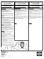
2. Place the cord grommet on the cord, the side with wire size marking “A”
shall face outward as shown in Fig. 2.
3. Remove output wire cover “B” from the unit (Fig. 3). Refer to the strip
gauge on back of device (Fig. 1), mark, cut and Strip cable outer jacket and
conductors “C”.
4. Lift gasket “E” away from housing and insert grommet in the gasket
“O” ring. Check if the grommet’s groove fits all around the gasket “O”
ring.
RENSEIGNEMENTS GÉNÉRAUX
1. AVIS - Doit être installé par un électricien qualifié conformément aux codes
de l'électricité nationaux et locaux et selon les directives suivantes
2. ATTENTION - RISQUE DE CHOC ÉLECTRIQUE. Débrancher le circuit
avant de procéder au montage. Ne jamais câbler des composants électriques
dans un circuit sous tension.
3. S’assurer que le type et les caractéristiques nominales de ce dispositif
conviennent à l'application. Cet IDALT est prévu pour usage avec un
disjoncteur de 60Hz 120 V, ca 20A max.
4..
5. AVERTISSEMENT : Un IDALT ne protège pas contre les chocs électriques
résultant d’un défaut dans la source d’alimentation du dispositif. Cet IDALT ne
protège pas contre les chocs électriques résultant d’un contact personnel avec
les deux côtés de la sortie électrique du dispositif.
6..
7.
8..
9.
10
MONTAGE
INFORMACIÓN GENERAL
1. AVISO - Para ser instalado por un electricista calificado, de acuerdo con los
códigos eléctricos nacionales y locales, y siguiendo estas instrucciones.
2. ¡CUIDADO! - RIESGO DE CHOQUE ELÉCTRICO. Desconectar la corriente
antes de la instalación. No conectar nunca componentes eléctricos en un
circuito energizado.
3. Asegurarse de que el tipo y las características nominales del dispositivo sean
apropiados para la aplicación. Este dispositivo GFCI está destinado a ser
usado exclusivamente con un circuito de 60Hz 120 V CA, 20A máx.
4..
5. ¡ATENCIÓN!: Un GFCI no protegerá contra choques eléctricos resultantes
de un defecto o una falla en la alimentación de energía al interruptor. Un GFCI
no protegerá contra los choques resultantes del contacto personal con ambos
lados de la salida eléctrica del interruptor.
6..
7..
8..
9.
10.
INSTALACIÓN
A
Fig. 1
Fig. 2
C
B
Fig. 3
E
O
C

PD 3023 (Page 2) 10/22
English
Français
Español
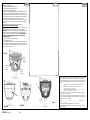
5. Loosen the terminal screws, connect conductors to the
Terminals as follow (FIG. 4):
The green wire to the terminal marked “G”.
The white wire to the terminal marked “N”.
The black wire to terminal marked “L”.
Secure the screws tightly, torque 8 lbf●in [0.9 N●m], make sure the
connections are properly oriented and there are no loose strands.
6. Slide the gasket “E” into place and press firmly into housing. (Fig. 5)
7. Install the provided cord clamp “F” with mating screws, alternating
between them until the cord clamp holds the cord securely.
8. Re-Install the output wiring cover “B” with mating screws (Fig. 6A &
6B). Make sure to alternate between them until the cover is tightly
secured.
9. Refer step 2 to 8 above for the input cord installation.
OPERATION AND TEST INSTRUCTIONS.
WARNING: If the GFCI fails to trip when the “TEST” button is pressed
or fails to reset, the device is defective and should be replaced.
WARNING: If the GFCI tests properly without a load applied, but trips
each time a load is connected, then the load has a ground fault
condition and needs to be repaired or replaced. DO NOT BYPASS
THE GFCI IF THIS CONDITION OCCOURS, A REAL SHOCK
HAZARD MAY EXIST.
1. Plug GFCI into a 120 Vac power outlet.
2. Press “RESET” button.
3. Verify if the indicator lens shows red, this indicates output voltage.
4. Press “TEST” button, verify the red in the indicator lens disappears.
5. Press “RESET” button again, verify the red indicator is visible.
6. The GFCI is ready for use.
Hubbell Products México, S. de R.L. de C.V. garantiza este producto, de estar libre de
defectos en materiales y mano de obra por un año a partir de su compra. Hubbell
reparará o reemplazará el artículo a su criterio juicio en un plazo no mayor de 90 días.
Esta garantía no cubre desgastes por uso normal y no será válida en los siguientes
casos a) Cuando el producto se hubiese utilizado en condiciones distintas a las
normales.
b) Cuando el producto no hubiese sido operado de acuerdo con el
instructivo de uso que se le acompaña
c) Cuando el producto hubiese sido alterado o reparado por personas no
autorizadas por el importador responsable.
El vendedor no otorga otras garantías y excluye expresamente daños incidentales o
consecuenciales inherentes a su uso.
Para hacer efectiva la garantía bastara la presentación del producto, acompañado de
la póliza correspondiente, debidamente sellada por el establecimiento que lo vendió o
bien la factura, recibo o comprobante.
Modelo: ___________________ Marca: _________________ Fecha de compra:
____________________
Importado por HUBBELL PRODUCTS MÉXlCO S. DE R.L. DE C.V.
Calle 5 Sur # 104, Parque industrial Toluca 2000, Toluca Edo de México. C.P. 50200.
Tel.:(722) 980 0600
1..
2.
3.
4.
5.
6..
1.
2.
3.
4.
5.
6.
E
B
Green
Vert
Verde
Fig. 4
Fig. 5
Black
Noir
Negro
White
Blanc
Blanco
F
Fig. 6A
Fig. 6B
-
 1
1
-
 2
2


Hubbell Wiring Device-Kellems PD3023 Guía de instalación
- Tipo
- Guía de instalación
en otros idiomas
Artículos relacionados
-
Hubbell Wiring Device-Kellems PD3026 Guía de instalación
-
-
-
-
-
-
-
-
-