
WP2000 A REMOTE LOCATION MULTI-PURPOSE POST
This unit (weatherproof outlet box & cover) can be used outdoors or in wet locations
(protects receptacles and timers while in use for unattended applications). It is cCSAus Certified,
TYPE 3R rated and meets National Electrical Code requirements
.
Contents
The following items are included:
• Weatherproof cover & housing
• Base cover
• Toggle, round, GFCI and duplex inserts
• Baggie with mtg. hardware & reducer bushings.
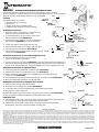
Installation Instructions
1. Determine number and size of PVC connections to be
made to the base of the Multi-Purpose post.
2. Use provided plugs to cap any entrance ports on the
base that will not be used (DIAGRAM A).
3. Use appropriate PVC reducers and secure to the base
where needed. (DIAGRAM B for reducer orientation)
4. Secure any reducers and/or plugs with PVC glue.
5.
Mount and secure base on PVC feeders with PVC glue.
6.
Attach ground wire to ground bar (DIAGRAM D)
7.
Attach Multi-Purpose post body to base using the four (4)
screws provided (DIAGRAM C)
Installation Instructions for use with wiring device only
8. Install selected wiring device to post according
to device manufacturer’s instructions.
9. Install selected insert over device (DIAGRAM E). Select the right insert for the application. If
you need to remove the knockouts on the round insert, grab them from the back with pliers
and pry down until they break free. Using round insert, knock out the appropriate hole size.
Installation Instructions for Optional Timer:
10. Select the Intermatic PB912M10R or PB313K Timer (DIAGRAM F)
11. Remove blank cover from top of Multi-Purpose post (DIAGRAM F)
12. Feed selected timer through open base of Multi-Purpose post and mount using
screws provided (DIAGRAM F)
13. Attach Multi-Purpose post body to base using the four (4) screws provided (DIAGRAMC)
14. Wire using installation instructions provided with timer
Installations Instructions for Optional Photo Control
15. Select an Intermatic K40 series Photo Control
16. Determine hole size needed for mounting (DIAGRAM G)
17. Locate drill pattern on back of Multi-Purpose post and drill required outlet
18. Mount Photo Control in outlet port.
19.
Attach Multi-Purpose post body to base using the four (4) screws provided (DIAGRAM C)
20. Wire according to installation instructions provided with Photo Control.
Installation Tips:
21. Optional Timer and/or Photo Controls should be mounted to Multi-Purpose post body prior
to mounting front device attaching body to bottom mounting plate.
22. Optional Timer and/or Photo Control wiring connections should be performed after
Multi-Purpose post body is attached to bottom mounting plate.
Limited One Year Warranty
If within one (1) year from the date of purchase, this product fails due to a defect in material or workmanship, Intermatic Incorporated will repair or replace it, at its sole option, free of charge. This warranty is extended
to the original household purchaser only and is not transferable. This warranty does not apply to: (a) damage to units caused by accident, dropping or abuse in handling, acts of God or any negligent use; (b) units
which have been subject to unauthorized repair, opened, taken apart or otherwise modified; (c) units not used in accordance with instructions; (d) damages exceeding the cost of the product; (e) sealed lamps and/or
lamp bulbs, LED’s and batteries; (f) the finish on any portion of the product, such as surface and/or weathering, as this is considered normal wear and tear; (g) transit damage, initial installation costs, removal costs,
or reinstallation costs.
INTERMATIC INCORPORATED WILL NOT BE LIABLE FOR INCIDENTAL OR CONSEQUENTIAL DAMAGES. SOME STATES DO NOT ALLOW THE EXCLUSION OR LIMITATION OF INCIDENTAL OR
CONSEQUENTIAL DAMAGES, SO THE ABOVE LIMITATION OR EXCLUSION MAY NOT APPLY TO YOU. THIS WARRANTY IS IN LIEU OF ALL OTHER EXPRESS OR IMPLIED WARRANTIES. ALL IMPLIED
WARRANTIES, INCLUDING THE WARRANTY OF MERCHANTABILITYAND THE WARRANTY OF FITNESS FOR A PARTICULAR PURPOSE, ARE HEREBYMODIFIED TO EXIST ONLYAS CONTAINED IN THIS
LIMITED WARRANTY, AND SHALL BE OF THE SAME DURATION AS THE WARRANTY PERIOD STATED ABOVE. SOME STATES DO NOT ALLOW LIMITATIONS ON THE DURATION OF AN IMPLIED
WARRANTY, SO THE ABOVE LIMITATION MAY NOTAPPLY TO YOU.
This warranty service is available by either (a) returning the product to the dealer from whom the unit was purchased, or (b) mailing the product, along with proof of purchase, postage prepaid to the authorized
service center listed below. This warranty is made by: Intermatic Incorporated/After Sales Service/7777 Winn Rd., Spring Grove, Illinois 60081-9698/815-675-7000 http://www.intermatic.com Please be sure to wrap
the product securely to avoid shipping damage.
IINNTTEERRMMAATTIICC IINNCCOORRPPOORRAATTEEDD
SPRING GROVE, ILLINOIS 60081-9698
158WP12545
BASE
CAP UNUSED
HOLES WITH
PLUGS
1” PIPE
INSTALL
DIRECTLY
INTO
BASE
FIRST INSTALL
REDUCER BUSHING
INTO BASE INSTALL
1/2 PIPE TO STOP
1/2” PIPE
3/4” PIPE
FIRST INSTALL
REDUCER BREAK OFF
STOP AND INSTALL 3/4 PIPE
BREAK OFF STOP
BASE
1/2” PIPE STOP
DIAGRAM A
DIAGRAM B
DIAGRAM C
DIAGRAM E
DIAGRAM F
DIAGRAM G
SCREW (4)
HOUSING
BASE
KNOCKOUT REMOVAL
HOUSING
HOUSING
REMOVE
COVER
PB313EK
PB912M10R
TIMER
MOUNTING
SCREWS
DRILL HOLE
TO MOUNT
PHOTO CONTROL
K40XX
PHOTO CONTROL
DIAGRAM D
GROUND BAR
GROUND WIRE

WP2000 POSTE DE UBICACIÓN REMOTA MULTIPROPÓSITO
La unidad (caja y cubierta a prueba de intemperie) se puede utilizar en exteriores y en lugares con
humedad (protege los receptáculos y los temporizadores cuando funcionan en aplicaciones no
atendidas). Está certificada según CSA, posee la clasificación TIPO 3R y cumple los requisitos
del Código Eléctrico Nacional (EE.UU.).
Contenido
Se incluyen los siguientes artículos:
• Cubierta y alojamiento para la intemperie
• Cubierta de base
• Insertos acodado, redondo, GFCI y dúplex
• Bolsas con tornillos de montaje y casquillos reductores
Instrucciones de instalación
1.
Determine el número y tamaño de las conexiones de PVC a la base
del poste multipropósito que se necesiten.
2. Emplee los tapones suministrados para cerrar todos los puertos de
entrada sin uso en la base (DIAGRAMA
A).
3. Emplee los reductores de PVC correctos y fíjelos a la base
cuando sea necesario (véase la orientación de los reductores
en el DIAGRAMA B).
4. Fije los reductores y/o los tapones con pegamento para PVC.
5. Monte y fije la base en las tomas de alimentación de PVC con
pegamento para PVC.
6.
Conecte el cable de masa alabarra de masa(DIAGRAMAD).
7. Instale la estructura del poste multipropósito sobre la base
con los cuatro (4) tornillos suministrados (DIAGRAMA C).
Instrucciones de instalación para uso con un dispositivo de
cableado
8. Instale el dispositivo de cableado en el poste siguiendo las
instrucciones del fabricante.
9.
Monte el inserto seleccionado sobre el dispositivo (DIAGRAMA E). Seleccione el inserto adecuado
para la aplicación. Si tiene que extraer alguna tapa de cables del inserto redondo, presiónela
hacia abajo con unos alicates en la parte trasera hasta que se suelte. En el inserto redondo,
extraiga la tapa del orificio que sea del tamaño adecuado.
Instrucciones de instalación para el temporizador opcional
10. Elija el temporizador PB912M10R o el PB313K (DIAGRAMA
F).
11. Extraiga la tapa obturadora en la parte superior del poste multipropósito (DIAGRAMA F).
12. Introduzca el temporizador por la base abierta del poste multipropósito e instálelo con los
tornillos suministrados (DIAGRAMA
F).
13. Monte la estructura del poste multipropósito sobre la base con los cuatro (4) tornillos
suministrados (DIAGRAMA C).
14. Realice el cableado siguiendo las instrucciones de instalación del temporizador.
Instrucciones de instalación para el fotocontrol opcionall
15. Elija un fotocontrol de serie K40 Intermatic.
16. Determine el tamaño del orificio necesario para la instalación (DIAGRAMA F).
17. Localice el orificio marcado en la parte trasera del poste multipropósito y taladre el puerto
de salida requerido.
18. Monte el fotocontrol en el puerto de salida.
19. Instale la estructura del poste multipropósito sobre la base con los cuatro (4) tornillos
suministrados (DIAGRAMA C).
20. Realice el cableado siguiendo las instrucciones de instalación del fotocontrol.
Consejos de instalación
21. El temporizador y/o el fotocontrol opcionales se deben montar en la estructura del poste
multipropósito antes de instalar la estructura delantera del dispositivo sobre la placa de montaje
inferior
.
22. El cableado del temporizador y/o el fotocontrol opcionales se debe conectar después de instalar la
estructura del poste multipropósito sobre la placa de montaje inferior.
Garantía limitada de 1 año
Si en el plazo de un (1) año contado desde la fecha de compra, el producto falla debido a un defecto de material o mano de obra, Intermatic Incorporated lo reparará o reemplazará, a su juicio, sin
costo alguno. La garantía se otorga al comprador original y no es transferible. Esta garantía no se aplica en los siguientes casos: (a) daños en las unidades causados por accidentes, caídas o el uso
indebido; causas de fuerza mayor o uso negligente; (b) unidades que hayan sido sometidas a una reparación no autorizada, abiertas, desmontadas o modificadas de otra forma; (c) unidades no
utilizadas según las instrucciones; (d) daños que excedan del costo del producto; (e) lámparas selladas y/o bombillas de lámparas, indicadores LED y baterías; (f) el acabado de cualquier parte del
producto, como su superficie y/o por exposición a la intemperie, ya que esto se considera un desgaste normal; (g) daños durante el transporte, costos de instalación inicial, costos de retirada, o
costos de reinstalación.
INTERMATIC INCORPORATED NO ASUME RESPONSABILIDAD ALGUNA POR DAÑOS INDIRECTOS O CONSECUENTES. ALGUNOS ESTADOS NO PERMITEN EXCLUIR O LIMITAR LOS DAÑOS
INDIRECTOS O CONSECUENTES, POR LO QUE LA LIMITACIÓN O EXCLUSIÓN ANTERIOR PUDIERA NO SER VÁLIDA EN SU CASO. ESTA GARANTÍA SUSTITUYE A CUALQUIER OTRA GARANTÍA
EXPRESA O IMPLÍCITA. TODAS LAS GARANTÍAS IMPLÍCITAS, INCLUIDA LA GARANTÍA DE IDONEIDAD COMERCIAL O DE IDONEIDAD PARA UN DETERMINADO FIN, SE MODIFICAN PARA QUEDAR
INCLUIDAS EN LA PRESENTE GARANTÍALIMITADA, Y TENDRÁN LA MISMADURACIÓN QUE EL PERIODO DE GARANTÍA MENCIONADO. ALGUNOS ESTADOS NO PERMITEN LIMITAR LA DURACIÓN
DE UNA GARANTÍA IMPLÍCITA, POR LO QUE LA LIMITACIÓN ANTERIOR PUDIERA NO SER APLICABLE EN SU CASO.
El servicio de garantía está disponible (a) mediante devolución del producto al distribuidor al que se adquirió, o (b) enviando el producto, acompañado de su prueba de compra, por correo postal
prepagado a un centro de servicio autorizado enumerado en la lista. Esta garantía es concedida por Intermatic Incorporated/After Sales Service/7777 Winn Rd., Spring Grove, Illinois 60081-9698/815-
675-7000 http://www.intermatic.com. Asegúrese de envolver bien el producto para evitar daños durante el transporte.
IINNTTEERRMMAATTIICC IINNCCOORRPPOORRAATTEEDD
SPRING GROVE, ILLINOIS 60081-9698
158WP12545
BASE
CERRAR CON
TAPONES LOS
ORIFICIOS SIN USO
DIAGRAMA A
INSTALAR EL
TUBO DE 1”
EN LA
BASE
PRIMERO INSTALAR EL
CASQUILLO REDUCTOR EN LA
BASE - INSTALAR EL TUBO DE
1/2” EN SU TOPE
TUBO DE 1/2”
PRIMERO INSTALAR EL REDUCTOR -
TOPE DE DESENGANCHE E INSTALAR
EL TUBO DE 3/4”
TOPE DE DESENGANCHE DEL TUBO
DE 3/4”
TOPE DE TUBO DE 1/2”
DIAGRAMA A
DIAGRAMA B
DIAGRAMA C
DIAGRAMA E
DIAGRAMA F
DIAGRAMA G
TORNILLO (4)
ALOJAMIENTO
BASE
EXTRACCIÓN DE TAPA DE CABLES
ALOJAMIENTO
ALOJAMIENTO
RETIRAR LA
TAPA
TEMPORIZADOR
PB313EK
PB912M10R
TIMER
TORNILLOS
DE
MONTAJE
TALADRAR EL
ORIFICIO PARA
MONTAR EL
FOTOCONTROL
FOTOCONTROL
K40XX
BARRA DE MASA
CABLE DE MASA
DIAGRAMA D
-
 1
1
-
 2
2


en otros idiomas
- English: Intermatic WP2000 User manual
Artículos relacionados
-
Intermatic WP1250MXD Instrucciones de operación
-
Intermatic SP640B Instrucciones de operación
-
-
-
-
-
-
-
Intermatic EJ600 Series Installation And User Instructions Manual
-