Poulan Pro HDF550 Manual de usuario
- Categoría
- Mini cultivadores
- Tipo
- Manual de usuario

OPERATOR'S MANUAL
MODEL:
HDF550
FRONT TINE TILLER
ALWAYS WEAR EYE PROTECTION DURING OPERATION
Visit our website: www.poulan.com
• Español, p. 18
WARNING:
Read this Man u al and follow all Warnings and
Safety Instructions. Fail ure to do so can re sult
in serious in ju ry.
IMPORTANT MANUAL Do Not Throw Away
194793 Rev. 1 12.05.04 TR
Printed in U.S.A.

2
• Keep children and pets away.
• Do not overload the machine capacity by attempting
to till too deep at too fast a rate.
• Never operate the machine at high speeds on slippery
surfaces. Look behind and use care when backing.
• Never allow bystanders near the unit.
• Use only attachments and accessories approved by
the manufacturer of the tiller.
• Never operate the tiller without good visibility or light.
• Be careful when tilling in hard ground. The tines may
catch in the ground and propel the tiller forward. If this
occurs, let go of the handlebars and do not restrain the
machine.
MAINTENANCE AND STORAGE
• Keep machine, attachments, and accessories in safe
work ing condition.
• Check shear pins, engine mounting bolts, and other
bolts at frequent intervals for proper tightness to be
sure the equip ment is in safe working condition.
• Never store the machine with fuel in the fuel tank inside
a building where ignition sources are present, such
as hot water and space heaters, clothes dryers, and
the like. Allow the engine to cool before storing in any
enclosure.
• Always refer to the operator’s guide instructions for
im por tant details if the tiller is to be stored for an ex-
tended period.
- IMPORTANT -
CAUTIONS, IMPORTANTS, AND NOTES ARE A MEANS OF
ATTRACTING ATTENTION TO IMPORTANT OR CRIT I CAL
IN FOR MA TION IN THIS MANUAL.
IMPORTANT: USED TO ALERT YOU THAT THERE IS A
POS SI BIL I TY OF DAM AG ING THIS EQUIP MENT.
NOTE: Gives essential information that will aid you to
better un der stand, incorporate, or execute a particular set
of instructions.
Look for this symbol to point out im-
por tant safety precautions. It means
CAUTION!!! BE COME ALERT!!! YOUR
SAFE TY IS INVOLVED.
CAUTION: Always disconnect spark
plug wire and place wire where it can-
not contact spark plug in order to pre-
vent ac ci den tal starting when setting
up, trans port ing, adjusting or making
re pairs.
SAFETY RULES
Safe Operation Practices for Walk-Behind Powered Ro ta ry Tillers
TRAINING
• Read the Owner’s Manual care ful ly. Be thor ough ly
fa mil iar with the controls and the proper use of the
equip ment. Know how to stop the unit and disengage
the controls quickly.
• Never allow children to operate the equipment. Never
allow adults to op er ate the equipment without proper
instruction.
• Keep the area of operation clear of all persons, par-
tic u lar ly small children, and pets.
PREPARATION
• Thoroughly inspect the area where the equipment is
to be used and remove all foreign objects.
• Disengage all clutches and shift into neutral before
starting the engine (mo tor).
• Do not operate the equipment with out wearing ad e -
quate outer gar ments. Wear footwear that will im prove
footing on slippery surfaces.
• Handle fuel with care; it is highly fl ammable.
• Use an approved fuel container.
• Never add fuel to a running engine or hot engine.
• Fill fuel tank outdoors with extreme care. Never fi ll fuel
tank indoors.
• Replace gasoline cap securely and clean up spilled
fuel before restarting.
• Use extension cords and receptacles as specifi ed by
the manufacturer for all units with electric drive motors
or electric starting motors.
• Never attempt to make any adjustments while the
engine (motor) is running (except where specifi cally
rec om mend ed by manufacturer).
OPERATION
• Do not put hands or feet near or under rotating parts.
• Exercise extreme caution when op er at ing on or cross-
ing gravel drives, walks, or roads. Stay alert for hidden
hazards or traffi c. Do not carry pas sen gers.
• After striking a foreign object, stop the engine (motor),
remove the wire from the spark plug, thoroughly in spect
the tiller for any damage, and repair the damage before
restarting and op er at ing the tiller.
• Exercise caution to avoid slipping or falling.
• If the unit should start to vibrate ab nor mal ly, stop the
engine (motor) and check immediately for the cause.
Vi bra tion is generally a warning of trouble.
• Stop the engine (motor) when leaving the operating
position.
• Take all possible precautions when leav ing the ma chine
unattended. Disengage the tines, shift into neutral, and
stop the engine.
• Before cleaning, repairing, or inspecting, shut off the
engine and make certain all moving parts have stopped.
Disconnect the spark plug wire, and keep the wire away
from the plug to prevent accidental starting. Disconnect
the cord on electric motors.
• Do not run the engine indoors; exhaust fumes are
dangerous.
• Never operate the tiller without proper guards, plates,
or other safety protective devices in place.
WARNING
The engine exhaust from this product con-
tains chem i cals known to the State of Cal i -
for nia to cause cancer, birth defects, or other
reproductive harm.

3
PRODUCT SPECIFICATIONS
Gasoline Capacity: 3 Quarts (2.8L)
Unleaded Regular
Oil (API-SG-SL): SAE 30 (Above 32°F/0°C)
(Capacity: 20 oz./0.6L) SAE 5w-30(Below 32°F/0°C)
Spark Plug: Champion RC12YC
(Gap: .030"/0.76mm)
CONGRATULATIONS on your purchase of a new tiller. It
has been designed, en gi neered and manu fac tured to give
you the best pos sible de penda bil ity and per form ance.
Should you experience any prob lems you can not easily
remedy, please contact your nearest authorized service
center. We have com pe tent, well-trained tech ni cians and
the proper tools to service or repair this unit.
Please read and retain this manual. The in struc tions will
enable you to assemble and main tain your tiller prop erly.
Always observe the “SAFETY RULES”.
IMPORTANT: THIS UNIT IS EQUIPPED WITH AN INTERNAL
COMBUSTION ENGINE AND SHOULD NOT BE USED ON
OR NEAR ANY UNIMPROVED FOREST-COVERED, BRUSH-
COVERED OR GRASS COVERED LAND UNLESS THE
ENGINE'S EXHAUST SYSTEM IS EQUIPPED WITH A SPARK
ARRESTER MEETING APPLICABLE LOCAL LAWS (IF ANY).
IF A SPARK ARRESTER IS USED, IT SHOULD BE MAINTAINED
IN EFFECTIVE WORK ING ORDER BY THE OPERATOR.
IN THE STATE OF CALIFORNIA, A SPARK ARRESTER IS
REQUIRED BY LAW (SECTION 4442 OF THE CALIFORNIA
PUBLIC RESOURCES CODE). OTHER STATES MAY HAVE
SIMILAR LAWS. FEDERAL LAWS APPLY ON FEDERAL LANDS.
SEE YOUR AUTHORIZED SERVICE CENTER/DEPARTMENT
FOR SPARK ARRESTER.
CUSTOMER RESPONSIBILITIES
• Read and observe the safety rules.
• Follow a regular schedule in maintaining, caring for
and using your tiller.
• Follow instructions under “Maintenance” and “Stor age”
sections of this Manual.
MAINTENANCE .....................................................10-12
SERVICE & ADJUSTMENTS .................................12-14
STORAGE .................................................................... 15
TROUBLESHOOTING ................................................. 16
WARRANTY................................................................. 17
ESPAÑOL .................................................................... 18
SAFETY RULES ............................................................ 2
PRODUCT SPECIFICATIONS....................................... 3
CUSTOMER RESPONSIBILITIES................................. 3
ASSEMBLY.................................................................4-5
OPERATION ............................................................... 6-9
MAINTENANCE SCHEDULE ...................................... 10
TABLE OF CONTENTS

4
ASSEMBLY
OPERATOR’S POSITION (See Fig. 1)
When right or left hand is mentioned in this manual, it
means when you are in the operating position (standing
behind tiller handles).
Your new tiller has been assembled at the factory with exception of those parts left unassembled for shipping purposes.
To ensure safe and proper operation of your tiller all parts and hardware you assemble must be tightened securely. Use
the correct tools as necessary to insure proper tightness.
TOOLS REQUIRED FOR ASSEMBLY
A socket wrench set will make assembly easier. Standard
wrench sizes are listed.
(1) Utility knife
(1) Screwdriver
(2) 1/2" wrenches
OPERATOR'S POSITION
RIGHT
FRONT
LEFT
overhead_views_8
FIG. 1
(6) Lock Washers 5/16 (6) Hex Nuts 5/16-18
(2) Hex Bolts 5/16-18 x 1-1/4
(2) Hex Bolts 5/16-18 x 3/4 (2) Hex Bolts 5/16-18 x 1 (4) Washers 3/8 x 7/8 x 14
CONTENTS OF HARDWARE PACK

5
UNPACK CARTON & INSTALL HANDLE
(See Fig. 2)
CAUTION: Be careful of exposed
sta ples when handling or disposing
of cartoning material.
IMPORTANT: WHEN UNPACKING AND AS SEM BLING
TILLER, BE CAREFUL NOT TO STRETCH OR KINK
CABLE(S).
• Cut cable ties securing handles.
• Slowly lift handle as sem bly up, route cable(s) as shown
and align han dle holes with handle panel hole and
slot.
• Loosely assemble hardware as shown. Be sure the
shorter (3/4" long) hex bolt is assembled in lower
hole of handle. Repeat for opposite side. Tight en all
hardware se cure ly.
• Cut cable ties securing tiller to skid and remove tiller
from skid.
• Remove screws securing depth stake to skid and dis-
card the screws.
depth_stake_4
DEPTH
STAKE
SUPPORT
BOLT
HEX BOLTS,
LOCK WASH ERS,
AND HEX NUTS
DEPTH STAKE
SUPPORT
NUT “A”
ENGINE BRACK ET
HALVES
FIG. 3
STAKE
SPRING
TILLER
HANDLES
02051
CABLE(S)
FIG. 2
handles_38
HANDLE
PANEL
BOLTS
FLAT
WASHER HEX BOLT
5/16-18X3/4"
TILLER
HANDLE
HAN DLE
PANEL
NUT LOCK
WASH ER
HEX BOLT
5/16-18X1"
ASSEMBLY
HANDLE HEIGHT
• Handle height may be adjusted to better suit operator.
(See “HANDLE HEIGHT” in the Service and Ad just -
ments section of this manual).
TILLING WIDTH
• Tilling width may be adjusted to better handle your
tilling con di tions (See “TINE ARRANGEMENT” in the
Service and Adjustments section of this manual).
TINE OPERATION
• Check tine operation before fi rst use. (See “TINE OP-
ERATION CHECK” in the Service and Adjustments
section of this manual).
INSTALL DEPTH STAKE AS SEM BLY
(See Fig. 3)
• Loosen nut “A”.
• Insert stake support between engine brack et halves
with stake spring down.
• Bolt stake support to engine brackets with bolts, lock
washers and nuts. Tight en se curely. Tighten nut “A”.
• Depth stake must move freely. If it does not, loosen
support bolt.

6
KNOW YOUR TILLER
READ THIS MANUAL AND SAFETY RULES BEFORE OPERATING YOUR TILLER.
Compare the illustrations with your tiller to familiarize yourself with the location of various controls and adjustments. Save
this manual for future reference.
REVERSE TINE
CONTROL
These symbols may appear on your Tiller or in literature supplied with the product. Learn and understand their mean-
ing.
RECOIL
STARTER
HANDLE
DEPTH STAKE
TINE
SHIELD
CHOKE CONTROL
FORWARD TINE
CONTROL
TINES
THROTTLE
CONTROL
FIG. 4
MEETS ANSI SAFETY REQUIREMENTS
Our tillers conform to the safety standards of the American National Standards Institute.
CHOKE CONTROL - Used when starting a cold engine.
DEPTH STAKE - Controls forward speed and the depth at
which the tiller will dig.
FORWARD TINE CONTROL - Engages tines in forward
direction.
OPERATION
REVERSE TINE CONTROL - Engages tines in reverse
RECOIL STARTER HANDLE - Used to start the engine.
direction.
THROTTLE CONTROL - Controls engine speed.

7
handles_94
FORWARD TINE CON TROL IN
“OFF ” (UP) POSITION
REVERSE
CONTROL
engine_art_
71
CHOKE
CONTROL
THROTTLE
CONTROL
FORWARD TINE CON TROL
IN “ON” (DOWN) POSITION
TINE OPERATION (See Fig. 5)
FORWARD
• Squeeze forward tine control to handle.
REVERSE
• With forward tine control “OFF” (up) position, pull back
and hold reverse tine control.
FIG. 5
HOW TO USE YOUR TILLER
Know how to operate all controls before adding fuel and oil
or attempting to start engine.
The operation of any tiller can result in foreign objects thrown into the eyes, which can result
in severe eye damage. Always wear safety glasses or eye shields before starting your tiller
and while tilling. We recommend a wide vision safety mask for over spectacles or standard
safety glasses.
STOPPING (See Fig. 5)
TINES
• Release forward tine control to stop forward move-
ment.
• Release reverse tine control to stop reverse move-
ment.
ENGINE
• Move throttle control to “STOP” position.
• Never use choke to stop engine.
TILLING
The speed and depth of tilling is regulated by the position
of the depth stake and wheel height.
The depth stake should always be below the wheels for
digging. It serves as a brake to slow the tiller’s forward
motion to enable the tines to penetrate the ground. Also,
the more the depth stake is lowered into the ground the
deeper the tines will dig.
DEPTH STAKE (See Fig. 6)
Adjust depth stake by removing the hairpin clip and clevis
pin. Change depth stake to desired position. Replace the
clevis pin and hairpin clip.
• For normal tilling, set depth stake at the second or third
hole from the top.
WHEELS (See Fig. 6)
Adjust wheels by removing the hairpin clip and clevis pin.
Change wheel position. Replace the hairpin clip and clevis
pin.
• For normal tilling, set wheels at the second or third
hole from the top.
depth_stake_4
DEPTH
STAKE
STAKE
SPRING
HAIRPIN CLIP
AND CLEVIS PIN
WHEEL
FIG. 6
OPERATION

8
TO TRANSPORT
CAUTION: Before lifting or trans port ing,
allow tiller engine and muffl er to cool.
Disconnect spark plug wire. Drain
gasoline from fuel tank.
AROUND THE YARD
• Tip depth stake forward until it is held by the stake
spring.
• Push tiller handles down, raising tines off the ground.
• Push or pull tiller to desired location.
AROUND TOWN
• Disconnect spark plug wire.
• Drain fuel tank.
• Transport in upright position to prevent oil leakage.
FIG. 7
engine_art_4
OIL
FILLER
PLUG
OIL
LEVEL
BEFORE STARTING ENGINE
IMPORTANT: BE VERY CAREFUL NOT TO ALLOW DIRT
TO ENTER THE ENGINE WHEN CHECKING OR ADDING
OIL OR FUEL. USE CLEAN OIL AND FUEL AND STORE IN
AP PROVED, CLEAN, COVERED CONTAINERS. USE CLEAN
FILL FUNNELS.
FILL ENGINE WITH OIL (See Fig. 7)
• With engine level, remove engine oil fi ller plug.
• Fill engine with oil to point of overfl owing. For ap prox-
i mate ca pac i ty see “PRODUCT SPEC I FI CA TIONS” on
page 3 of this manual.
• Tilt tiller back on its wheels and then re-level.
• With engine level, refi ll to point of overfl owing if nec-
es sary. Re place oil fi ller plug.
• For cold weather operation you should change oil for
easier starting (See “OIL VISCOSITY CHART” in the
Maintenance section of this manual).
• To change engine oil, see the Maintenance section of
this manual.
OPERATION
TO START ENGINE (See Fig. 8)
CAUTION: Keep drive control bar in
“DISENGAGED” position when start-
ing en gine.
When starting engine for the fi rst time or if engine has run
out of fuel, it will take extra pulls of the recoil starter to
move fuel from the tank to the engine.
• Make sure spark plug wire is prop er ly connected.
• Move shift lever indicator to “N” (neutral) position.
• Place throttle control in “FAST” position.
• Turn fuel shut-off valve 1/4 turn to open position.
• Move choke control to choke position.
• Grasp recoil starter handle with one hand and grasp
tiller handle with other hand. Pull rope out slowly until
engine reaches start of com pres sion cycle (rope will
pull slightly harder at this point).
• Pull recoil starter handle quickly. Do not let starter
handle snap back against starter.
• If engine fi res but does not start, move choke control
to half choke position. Pull recoil starter handle until
engine starts.
• When engine starts, slowly move choke control to
"RUN" position as engine warms up.
NOTE: A warm engine requires less choking to start.
• Move throttle control to desired running position.
• Allow engine to warm up for a few minutes before
engaging tines.
ADD GASOLINE
• Fill fuel tank to bottom of fi ller neck. Do not overfi ll.
Use fresh, clean, regular un lead ed gasoline with a
minimum of 87 octane. (Use of leaded gasoline will
increase carbon and lead oxide deposits and reduce
valve life). Do not mix oil with gasoline. Purchase fuel
in quan ti ties that can be used within 30 days to assure
fuel freshness.
CAUTION: Fill to within 1/2 inch of top
of fuel tank to prevent spills and to allow
for fuel expansion. If gasoline is ac-
ci den tal ly spilled, move machine away
from area of spill. Avoid creating any
source of ignition until gasoline vapors
have disappeared.
Wipe off any spilled oil or fuel. Do not
store, spill or use gasoline near an
open fl ame.
IMPORTANT: WHEN OPERATING IN TEMPERATURES
BELOW32°F(0°C), USE FRESH, CLEAN WINTER GRADE
GAS O LINE TO HELP INSURE GOOD COLD WEATHER
START ING.
CAUTION: Alcohol blended fuels (called
gas o hol or using ethanol or methanol) can at-
tract moisture which leads to sep a ra tion and
for ma tion of acids during storage. Acidic gas
can damage the fuel system of an engine while
in storage. To avoid engine problems, the fuel
system should be emptied before stor age of
30 days or longer. Drain the gas tank, start
the engine and let it run until the fuel lines
and carburetor are empty. Use fresh fuel next
sea son. See Storage In struc tions for additional
information. Never use engine or carburetor
cleaner products in the fuel tank or permanent
damage may occur.

9
engine_art_
71
BREAKING IN YOUR TILLER
Break-in your belt(s), pulleys and tine control before you
actually begin tilling.
• Start engine, tip tines off ground by pressing handles
down and engage tine control to start tine rotation.
Allow tines to rotate for fi ve minutes.
• Check tine operation and adjust if necessary. See “TINE
OPERATION CHECK” in the Service and Ad just ments
sec tion of this manual.
TILLING HINTS
CAUTION: Until you are accustomed
to handling your tiller, start ac tu al fi eld
use with throttle in slow position.
To help tiller move forward, lift up the handles slightly (thus
lifting depth stake out of ground). To slow down the tiller,
press down on handles.
If you are straining or tiller is shaking, the wheels and depth
stake are not set properly in the soil being tilled. The proper
setting of the wheels and depth stake is through trial and
error and depends upon the soil con di tion. (The harder or
wetter the ground, the slower the engine and tine speed
needed. Under these poor con di tions, at fast speed the
tiller will run and jump over the ground).
A properly adjusted tiller will dig with little effort from the
operator.
• Tilling is digging into, turning over, and breaking up
packed soil before planting. Loose, unpacked soil helps
root growth. Best tilling depth is 4"-6". A tiller will also
clear the soil of unwanted vege ta tion. The de com po si tion
of this vegetable mat ter en rich es the soil. De pend ing
on the climate (rain fall and wind), it may be advisable
to till the soil at the end of the growing season to further
condition the soil.
• Soil conditions are important for proper tilling. Tines will
not readily penetrate dry, hard soil which may con trib ute
to excessive bounce and diffi cult handling of your tiller.
Hard soil should be mois tened before tilling; however,
extremely wet soil will “ball-up” or clump during tilling.
Wait until the soil is less wet in order to achieve the
best results. When tilling in the fall, remove vines and
long grass to prevent them from wrapping around the
tine shaft and slowing your tilling operation.
• You will fi nd tilling much easier if you leave a row un-
tilled between passes. Then go back between tilled
rows. (See Fig. 9) There are two reasons for doing
this. First, wide turns are much easier to negotiate than
about-faces. Sec ond, the tiller won’t be pulling itself,
and you, toward the row next to it.
• Set depth stake and wheel height for shallow tilling
when working extremely hard soil or sod. Then work
across the fi rst cuts at normal depth.
321
5
4
67
FIG. 9
CULTIVATING
Cultivating is destroying the weeds between rows to pre-
vent them from robbing nourishment and moisture from the
plants. At the same time, breaking up the upper layer of
soil crust will help retain moisture in the soil. Best digging
depth is 1"-3".
• You will probably not need to use the depth stake. Begin
by tipping the depth stake forward until it is held by the
stake spring.
• Cultivate up and down the rows at a speed which will
allow tines to uproot weeds and leave the ground in
rough con di tion, promoting no fur ther growth of weeds
and grass (See Fig. 10).
FIG. 10
OPERATION
FIG. 8
RECOIL STARTER
HANDLE
SPARK PLUG
CHOKE
CONTROL
THROTTLE
CONTROL
NOTE: If at a high altitude (3000 feet) or in cold
temperatures (below 32°F), the carburetor fuel mixture
may need to be adjusted for best engine performance.
See "TO ADJUST CARBURETOR" in the Service and
Adjustments section of this manual.
NOTE: If engine does not start, see troubleshooting
points.

10
MAINTENANCE
SCHEDULE
FILL IN DATES
AS YOU COMPLETE
REGULAR SERVICE
Check Engine Oil Level
Change Engine Oil
Oil Pivot Points
Inspect Air Screen
Inspect Spark Arrester / Muffler
Clean or Replace Air Cleaner Cartridge
Clean Engine Cylinder Fins
Replace Spark Plug
BEFORE EACH USE
EVERY 25 HOURS
EVERY 5 HOURS
EVERY 50 HOURS
SERVICE DATES
2
1 - Change more often when operating under a heavy load or in high ambient temperatures.
2 - Service more often when operating in dirty or dusty conditions.
MAINTENANCE
cSAE 30 OR 10W-30 MOTOR OIL
dREFER TO MAINTENANCE “ENGINE” SECTION
LUBRICATION CHART
d EN GINE
c TINE CON TROL
c IDLER
ARM
GENERAL RECOMMENDATIONS
The warranty on this tiller does not cover items that have
been subjected to operator abuse or negligence. To receive
full value from the warranty, the operator must main tain tiller
as instructed in this manual.
Some adjustments will need to be made periodically to
properly maintain your tiller.
At least once a season, check to see if you should make
any of the adjustments described in the Service and Ad-
justments section of this manual.
• Once a year you should replace the spark plug, clean
or replace air fi lter, and check tines and belts for wear.
A new spark plug and clean air fi lter assure proper
air-fuel mixture and help your engine run better and
last longer.
BEFORE EACH USE
• Check engine oil level.
• Check tine operation.
• Check for loose fasteners.
LUBRICATION
Keep unit well lubricated (See “LUBRICATION CHART”).

11
FIG. 11
engine_art_12
FIG. 12
OIL
DRAIN
PLUG
OIL FILLER
PLUG
OIL LEVEL
TEMPERATURE RANGE ANTICIPATED BEFORE NEXT OIL CHANGE
SAE VISCOSITY GRADES
-20 0 30 40 80 100
-30 -20 0 20 30 40
F
C
32
-10 10
60
5W-30
SAE 30
oil_visc_chart1_e
MAINTENANCE
AIR
CLEANER
SCREW
COV ER
AIR CLEAN ER CAR TRIDGE
FIG. 13
Disconnect spark plug wire before performing any maintenance (except car bu re tor adjustment) to
prevent accidental start ing of engine.
Prevent fi res! Keep the engine free of grass, leaves, spilled oil, or fuel. Re move fuel from tank
before tipping unit for maintenance. Clean muffl er area of all grass, dirt, and debris.
Do not touch hot muffl er or cylinder fi ns as contact may cause burns.
ENGINE
LUBRICATION
Use only high quality detergent oil rated with API service
classifi cation SG-SL. Select the oil’s SAE vis cos i ty grade
according to your expected temperature.
NOTE: Although multi-viscosity oils (5W-30, 10W-30, etc.)
improve starting in cold weather, these multi viscosity oils
will result in increased oil consumption when used above
32°F (0°C). Check your engine oil level more frequently to
avoid possible engine damage from running low on oil.
Change the oil after every 25 hours of operation or at least
once a year if the tiller is not used for 25 hours in one year.
Check the crankcase oil level before starting the engine
and after each fi ve (5) hours of continuous use. Add SAE
30 motor oil or equivalent. Tighten oil fi ller plug securely
each time you check the oil level.
TO CHANGE ENGINE OIL (See Figs. 11 and 12)
Determine temperature range expected before oil change.
All oil must meet API service classifi cation SG-SL.
• Be sure tiller is on level surface.
• Oil will drain more freely when warm.
• Catch oil in a suitable container.
• Remove drain plug.
• Tip tiller forward to drain oil.
• After oil has drained completely, replace oil drain plug
and tighten securely.
• Remove oil fi ller plug. Be careful not to allow dirt to
enter the engine.
• Refi ll engine with oil. See “CHECK ENGINE OIL LEVEL”
in the Operation section of this manual.
AIR CLEANER (See Fig. 13)
Service air cleaner cartridge every twenty-fi ve hours, more
often if engine is used in very dusty conditions.
• Loosen air cleaner screws, one on each side of
cover.
• Remove air cleaner cover.
• Carefully remove air cleaner cartridge. Be care ful. Do
not allow dirt or de bris to fall into carburetor.
• Clean by tapping gently on a fl at surface.
• If very dirty or damaged, replace cartridge.
• Clean and re place cover. Tighten screws securely.
CAUTION: Petroleum sol vents, such as
kerosene, are not to be used to clean
cartridge. They may cause de te ri o ra tion
of the cartridge. Do not oil car tridge.
Do not use pres sur ized air to clean or
dry cartridge.
engine_art_71
BLOWER
HOUSING
AIR
SCREEN
CYLINDER FINS
MUF FLER
FIG. 14
COOLING SYSTEM (See Fig. 14)
Your engine is air cooled. For proper engine performance
and long life keep your engine clean.
• Clean air screen frequently using a stiff-bristled-
brush.
• Remove blower housing and clean as nec es sary.
• Keep cylinder fi ns free of dirt and chaff.

12
TILLER
TO ADJUST HANDLE HEIGHT (See Fig. 15)
Factory assembly has provided lowest handle height. Se lect
handle height best suited for your tilling conditions. Handle
height will be different when tiller digs into soil.
• If a higher handle height is desired, loosen the four
nuts securing handle panel to engine brackets.
• Slide handle panel to desired location.
• Tighten the four nuts securely.
HANDLE
PANEL
ENGINE BRACKETS
NUTS (ALSO 2
ON LEFT SIDE
OF TILLER)
FIG. 15
SERVICE AND ADJUSTMENTS
CAUTION: Disconnect spark plug wire from spark plug and place wire where it cannot come into
contact with plug.
FIG. 16
FIG. 17
MAINTENANCE
MUFFLER
Do not operate tiller without muffl er. Do not tamper with
exhaust system. Damaged muffl ers or spark arresters could
create a fi re hazard. Inspect pe ri odi cally and re place if
nec es sary. If your engine is equipped with a spark arrester
screen assembly, re move every 50 hours for cleaning and
inspection. Re place if dam aged.
SPARK PLUG
Replace spark plugs at the beginning of each tilling sea-
son or after every 50 hours of use, whichever comes fi rst.
Spark plug type and gap setting are shown in “PROD UCT
SPEC I FI CA TIONS” on page 3 of this manual.
TRANSMISSION
Your transmission is sealed and will not require lubrication
unless serviced.
CLEANING
Do not clean your tiller when the engine and transmission
are hot. We do not rec om mend using pressurized water
(gar den hose, etc.) to clean your unit un less the gasket
area around the trans mis sion and the engine muf fl er, air
fi l ter and car bu re tor are cov ered to keep wa ter out. Wa ter
in en gine will short en the useful life of your tiller.
• Clean engine, wheels, fi nish, etc. of all foreign mat-
ter.
• Keep fi nished surfaces and wheels free of all gas o line,
oil, etc.
• Protect painted surfaces with au to mo tive type wax.
TINE ARRANGEMENT
Your outer tines can be assembled in several different ways
to suit your tilling or cultivating needs.
CAUTION: Tines are sharp. Wear
gloves or other protection when han-
dling tines.
tine_4
OUTER
TINE
INNER TINE
HAIRPIN CLIP
A
B
A
B
CLEVIS
PIN
MID-WIDTH TILLING - 24" PATH (See Fig. 17)
• Assemble holes “A” in tine hubs to holes “C” in tine
shaft.
tine_5
A
C
AC
NORMAL TILLING - 26" PATH (See Fig. 16)
• Assemble holes “A” in tine hubs to holes “B” in tine
shaft.

13
FIG. 18
NARROW TILLING/CULTIVATING - 12-3/4" PATH
(See Fig. 18)
• Remove outer tines.
tine_
6
INNER TINES ONLY
NOTE: When reassembling outer tines, be sure right tine
assembly (marked “R”) and left tine assembly (marked “L”)
are mounted to correct side of tine shaft.
SERVICE AND ADJUSTMENTS
TINE OPERATION CHECK (See Fig. 19)
WARNING: Disconnect spark plug wire
from spark plug to prevent starting while
checking tine operation.
For proper tine operation, forward tine control lever must be
against control body and all slack removed from inner wire of
control cable when control is in the “OFF” (up) position.
If lever and cable are loose, loosen cable clip at lower end of
cable. Pull up on cable to remove slack, without extending
spring on end of cable, and retighten cable clip.
FINAL CHECK “OFF” POSITION
• With tine control “OFF” (up), push down on handle to
raise tines off the ground.
• Slowly pull recoil starter handle while observing tines.
Tines should not rotate.
• If tines rotate, inner wire of control cable is too tight
which is extending lower spring and engaging tines.
Loosen cable clip and push down on cable only enough
to relieve spring tension. Tighten cable clip.
• Recheck in “OFF” position and adjust if necessary.
FINAL CHECK “ON” POSITION
• With tine control “ON” (held down to handle) push down
on handle to raise tines off the ground.
• Slowly pull recoil starter handle while observing tines.
Tines should rotate forward.
• If tines do not rotate, inner wire of control cable is too
loose. Loosen cable clip and pull cable up to remove
slack and retighten clip.
• Recheck in “ON” position and adjust if necessary.
NOTE: If “ON” position check required adjustment, re check
“OFF” position adjustment to insure tines do not rotate when
control is “OFF” (up).
FIG. 19
handles_94
FORWARD TINE
CONTROL IN “OFF”
(UP) POSITION
BODY
TINE CONTROL
“ON” POSITION
TINE
CON TROL
CABLE
CABLE
CLIP
TO REPLACE V-BELTS (See Figs. 21 and 22)
Replace V-belts if they have stretched considerably or if
they show cracks or frayed edges. There are two (2) V-belts
- forward (inside) and reverse (outside).
Belt guard must be removed to service belts. See “TO
REMOVE BELT GUARD” in this section of manual.
NOTE: Observe carefully routing of both belts and lo ca tion
of all belt guides before removing belts.
TO REMOVE BELT GUARD (See Fig. 20)
• Remove two (2) cap nuts and washers from side of
belt guard.
• Loosen (do not remove) tine shield nut on underside
of tine shield.
• Pull belt guard out and away from unit.
• Replace belt guard by reversing above procedure. Be
sure slot in bottom of belt guard is under head of tine
shield bolt and all nuts are tightened securely.
FIG. 20
CAP NUTS
AND WASH ERS
BELT
GUARD
TINE
SHIELD
NUT

14
SERVICE AND ADJUSTMENTS
belts_10
FIG. 22
FORWARD MOTION
(INSIDE) V-BELT
ENGINE PULLEY
REVERSE
IDLER ARM
REVERSE
IDLER PULLEY
IDLER
ARM PIN
FIG. 21
FORWARD
IDLER PULLEY
REVERSE
IDLER
PULLEY
ENGINE PUL-
LEY
FRONT VIEW REFERENCE
REVERSE (OUTSIDE) V-BELT
FORWARD MOTION (INSIDE) V-BELT
TRANS MIS SION
PUL LEY
BELT GUARD
BOLT
BELT
GUIDE
REVERSE
IDLER PULLEY IDLER
ARM PIN
ENGINE
PULLEY
REVERSE (OUTSIDE)
V-BELT
FORWARD IDLER
PUL LEY
REVERSE
IDLER PULLEY
ENGINE PULLEY
BELT GUIDE TRANS MIS SION
PULLEY
BELT GUIDE
FORWARD
IDLER PULLEY
ENGINE
TO AD JUST CARBURETOR
The carburetor has been preset at the factory and ad just ment
should not be necessary. However, engine per for mance
can be affected by dif fer enc es in fuel, tem per a ture, al ti tude
or load. If the carburetor does need ad just ment, contact
your nearest authorized service center/de part ment
IMPORTANT: NEVER TAMPER WITH THE ENGINE GOVERNOR,
WHICH IS FACTORY SET FOR PROPER ENGINE SPEED.
OVER SPEED ING THE ENGINE ABOVE THE FACTORY HIGH
SPEED SETTING CAN BE DANGEROUS. IF YOU THINK THE
ENGINE-GOVERNED HIGH SPEED NEEDS ADJUSTING,
CONTACT YOUR NEAREST AUTHORIZED SERVICE CENTER/
DEPARTMENT, WHICH HAS THE PROPER EQUIP MENT AND
EXPERIENCE TO MAKE ANY NEC ES SARY ADJUSTMENTS.
BELT REMOVAL
• Remove reverse idler pulley from idler arm.
• Remove reverse (outside) V-belt.
• Remove forward (inside) V-belt from transmission pul ley
fi rst and then from engine pulley.
BELT REPLACEMENT
• Install new forward (inside) V-belt to engine pulley fi rst
then to transmission pulley. Be sure belt is positioned
on inside groove of both pulleys, inside all belt guides
and rests on idler pulley.
• Before installing reverse (outside) V-belt, turn belt “in side
out”. Twist so wide, fl at surface of belt is to inside.
• Wrap V-belt around reverse idler pulley and re as semble
idler to idler arm. Tighten securely. Be sure belt is
between reverse idler pulley and idler arm pin.
• Install belt to outside groove of transmission pulley. Be
sure belt is inside all belt guides and rests on outside
groove of engine pulley.
CHECK TINE OPERATION
• See “TINE OPERATION CHECK” in this section of
manual.
REPLACE BELT GUARD

15
STORAGE
ENGINE OIL
Drain oil (with engine warm) and replace with clean oil. (See
“ENGINE” in the Maintenance section of this man ual).
CYLINDER(S)
• Remove spark plug.
• Pour 1 ounce (29 ml) of oil through spark plug hole into
cylinder.
• Pull starter handle slowly several times to distribute
oil.
• Replace with new spark plug.
OTHER
• Do not store gasoline from one season to another.
• Replace your gasoline can if your can starts to rust.
Rust and/or dirt in your gasoline will cause problems.
• If possible, store your unit indoors and cover it to give
protection from dust and dirt.
• Cover your unit with a suitable pro tec tive cover that
does not retain moisture. Do not use plastic. Plastic
cannot breathe which allows con den sa tion to form and
will cause your unit to rust.
IMPORTANT: NEVER COVER TILLER WHILE ENGINE AND
EXHAUST AREAS ARE STILL WARM.
Immediately prepare your tiller for storage at the end of the
season or if the unit will not be used for 30 days or more.
WARNING: Never store the tiller with
gasoline in the tank inside a build ing
where fumes may reach an open fl ame
or spark. Allow the engine to cool before
storing in any enclosure.
TILLER
• Clean entire tiller (See “CLEANING” in the Maintenance
section of this manual).
• Inspect and replace belts, if nec es sary (See belt re-
place ment in struc tions in the Service and Ad just ments
section of this manual).
• Lubricate as shown in the Maintenance section of this
manual.
• Be sure that all nuts, bolts and screws are securely
fastened. Inspect moving parts for damage, break age
and wear. Replace if necessary.
• Touch up all rusted or chipped paint surfaces; sand
lightly before painting.
ENGINE
FUEL SYSTEM
IMPORTANT: IT IS IMPORTANT TO PREVENT GUM DEPOSITS
FROM FORMING IN ESSENTIAL FUEL SYSTEM PARTS SUCH
AS THE CARBURETOR, FUEL FILTER, FUEL HOSE, OR TANK
DURING STORAGE. ALSO, EXPERIENCE INDICATES THAT
ALCOHOL BLENDED FUELS (CALLED GASOHOL OR USING
ETHANOL OR METHANOL) CAN ATTRACT MOISTURE WHICH
LEADS TO SEPARATION AND FORMATION OF ACIDS DURING
STORAGE. ACIDIC GAS CAN DAMAGE THE FUEL SYSTEM
OF AN ENGINE WHILE IN STORAGE.
• Empty the fuel tank by starting the engine and let it run
until the fuel lines and carburetor are empty.
• Never use engine or carburetor cleaner products in the
fuel tank or permanent.
• Use fresh fuel next season.
NOTE: Fuel stablizer is an acceptable alternative in
minimizing the formation of fuel gum deposits during
storage. Add stabilizer to gasoline in fuel tank or storage
container. Always follow the mix ratio found on stablizer
container. Run engine at least 10 minutes after adding
stablizer to allow the stabilizer to reach the carburetor.
Do not empty the gas tank and carburetor if using fuel
stabilizer.

16
Will not start 1. Out of fuel. 1. Fill fuel tank.
2. Engine not “CHOKED” properly. 2. See “TO START ENGINE” in the Operation section.
3. Engine fl ooded. 3. Wait several minutes before attempting to start.
4. Dirty air cleaner. 4. Clean or replace air cleaner cartridge.
5. Water in fuel. 5. Empty fuel tank and carburetor, and refi ll tank with
fresh gasoline.
6. Clogged fuel tank. 6. Remove fuel tank and clean.
7. Loose spark plug wire. 7. Make sure spark plug wire is seated properly on
plug.
8. Bad spark plug or improper gap. 8. Replace spark plug or adjust gap.
9. Carburetor out of adjustment. 9. Make necessary adjustments.
Hard to start 1. Throttle control not set properly. 1. Place throttle control in “FAST” position.
2. Dirty air cleaner. 2. Clean or replace air cleaner cartridge.
3. Bad spark plug or improper gap. 3. Replace spark plug or adjust gap.
4. Stale or dirty fuel. 4. Empty fuel tank and refi ll with fresh gasoline.
5. Loose spark plug wire. 5. Make sure spark plug wire is seated properly on
plug.
6. Carburetor out of adjustment. 6. Make necessary adjustments.
Loss of power 1. Engine is overloaded. 1. Set depth stake and wheels for shallower tilling.
2. Dirty air cleaner. 2. Clean or replace air cleaner cartridge.
3. Low oil level/dirty oil. 3. Check oil level/change oil.
4. Faulty spark plug. 4. Clean and regap or change spark plug.
5. Oil in fuel. 5. Empty and clean fuel tank and refi ll, and clean
carburetor.
6. Stale or dirty fuel. 6. Empty fuel tank and refi ll with fresh gasoline.
7. Water in fuel. 7. Empty fuel tank and carburetor, and refi ll tank with
fresh gasoline.
8. Clogged fuel tank. 8. Remove fuel tank and clean.
9. Spark plug wire loose. 9. Connect and tighten spark plug wire.
10. Dirty engine air screen. 10. Clean engine air screen.
11. Dirty/clogged muffl er. 11. Clean/replace muffl er.
12. Carburetor out of adjustment. 12. Make necessary adjustments.
13. Poor compression. 13. Contact an authorized service center/department.
Engine overheats 1. Low oil level/dirty oil. 1. Check oil level/change oil.
2. Dirty engine air screen. 2. Clean engine air screen.
3. Dirty engine. 3. Clean cylinder fi ns, air screen, muffl er area.
4. Partially plugged muffl er. 4. Remove and clean muffl er.
5. Improper carburetor adjustment. 5. Adjust carburetor to richer position.
Excessive bounce/ 1. Ground too dry and hard. 1. Moisten ground or wait for more favorable soil
diffi cult handling conditions.
2. Wheels and depth stake incorrectly adjusted. 2. Adjust wheels and depth stake.
Soil balls up or clumps 1. Ground too wet. 1. Wait for more favorable soil conditions.
Engine runs but tiller 1. Tine control is not engaged. 1. Engage tine control.
won’t move 2. V-belt not correctly adjusted. 2. Inspect/adjust V-belt.
3. V-belt is off pulley(s). 3. Inspect V-belt.
Engine runs but labors 1. Tilling too deep. 1. Set depth stake for shallower tilling.
when tilling 2. Throttle control not properly adjusted. 2. Check throttle control setting.
3. Carburetor out of adjustment. 3. Make necessary adjustments.
PROBLEM CAUSE CORRECTION
TROUBLESHOOTING POINTS

17
LIMITED WARRANTY
The Manufacturer warrants to the original consumer purchaser that this product as manufactured is free from de-
fects in materials and work man ship. For a period of two (2) years from date of purchase by the original consumer
purchaser, we will repair or replace, at our option, without charge for parts or labor incurred in replacing parts, any
part which we fi nd to be defective due to materials or workmanship. This Warranty is subject to the following limita-
tions and exclusions.
1. This warranty does not apply to the engine or components parts thereof. Please refer to the applicable manu-
facturer's warranty on these items.
2. Transportation charges for the movement of any power equipment unit or attachment are the responsibility of
the pur chaser. Transportation charges for any parts submitted for replacement under this warranty must be paid
by the purchaser unless such return is requested by Electrolux Home Products.
3. The Warranty period for any products used for rental or commercial purposes is limited to 90 days from the date
of original purchase.
4. This Warranty applies only to products which have been properly assembled, adjusted, operated, and maintained
in ac cor dance with the instructions furnished. This Warranty does not apply to any product which has been
subjected to alteration, misuse, abuse, improper assembly or installation, delivery damage, or to normal wear
of the product.
5. Exclusions: Excluded from this Warranty are belts, tines, tine adapters, normal wear, normal adjustments, stan-
dard hard ware and normal maintenance.
6. In the event you have a claim under this Warranty, you must return the product to an authorized service deal-
er.
Should you have any unanswered questions concerning this Warranty, please contact:
giving the model number, serial number and date of purchase of your product and the name and address of the
authorized dealer from whom it was purchased.
THIS WARRANTY DOES NOT APPLY TO INCIDENTAL OR CONSEQUENTIAL DAMAGES AND ANY IMPLIED
WAR RAN TIES ARE LIMITED TO THE SAME TIME PERIODS STATED HEREIN FOR OUR EXPRESSED WAR-
RANTIES. Some areas do not allow the limitation of consequential damages or limitations of how long an implied
Warranty may last, so the above limitations or exclusions may not apply to you. This Warranty gives you specifi c legal
rights, and you may have other rights which vary from locale to locale.
This is a limited Warranty within the meaning of that term as defi ned in the Magnuson-Moss Act of 1975.
In Canada contact:
Electrolux Canada Corp.
7075 Ordan Drive
Mississauga, Ontario
L5T 1K6
Electrolux Home Products, Inc.
Outdoor Products Customer Service Dept.
1030 Stevens Creek Road
Augusta, GA 30907 USA

18
ADVERTENCIA
Es conocido por el Estado de California que los
gases de escape del motor de este productor
contienen químicos los cuales a ciertos niveles,
pueden ocasionar, cáncer, defectos de nacimiento,
y otros daños al sistema reproductivo.
REGLAS DE SEGURIDAD
Prácticas de Operación Seguras para las Cultivadoras Rotatorias Empujables a Motor
ENTRENAMIENTO
• Lea el Manual del Dueño cuidadosamente. Familiarícese
completamente con los controles y con el uso adecuado
del equipo. Sepa cómo parar la unidad y desenganchar los
controles rápidamente.
• Nunca permita que los niños operen el equipo. Nunca permita
que los adultos operen el equipo sin los conocimientos
adecuados.
• Mantenga el área de operación despejada de personas,
especialmente niños pequeños y animales domésticos.
PREPARACIÓN
• Inspeccione cuidadosamente el área en donde se va usar
el equipo y remueva los objetos extraños.
• Desenganche todos los embragues y cambie a neutro antes
de hacer arrancar el motor.
• No opere el equipo sin usar ropa exterior adecuada.
Use zapatos que mejoren el equilibrio en superfi cies
resbalosas.
• Maneje el combustible con cuidado pues es muy
infl amable.
• Use un envase de combustible aprobado.
• Nunca añada combustible a un motor en funcionamiento o
caliente.
• Llene el estanque de combustible afuera con mucho cuidado.
Nunca llene el estanque de combustible en un recinto
cerrado.
• Vuelva a colocar la tapa del depósito de gasolina en forma
segura y limpie el combustible derramado antes de volver a
arrancar.
• Use cordones de extensión y receptáculos, según las
especifi caciones del fabricante, para todas las unidades con
motores de impulsión o con motores de arranque eléctrico.
• Nunca trate de hacer ningún ajuste mientras que el motor
esté funcionando (excepto en los casos específi camente
recomendados por el fabricante).
OPERACIÓN
• No ponga ni las manos ni los pies cerca o debajo de las
piezas rotatorias.
• Tenga mucho cuidado cuando opere o cruce entradas para
automóviles de ripio, senderos o caminos. Esté alerta en lo
que se refi ere a los peligros escondidos o al tráfi co. No lleve
pasajeros.
• Después de pegarle a un objeto extraño, pare el motor,
remueva el alambre de la bujía, inspeccione la cultivadora
cuidadosamente, para verifi car si hay daños, y repare el
daño antes de volver a arrancar y operar la cultivadora.
• Tenga cuidado para evitar resbalarse o caerse.
• Si la unidad empieza a vibrar anormalmente, pare el motor y
revísela inmediatamente para verifi car la causa. La vibración
normalmente es un aviso de problemas.
• Pare el motor cuando abandone la posición de operación.
• Tome todas las precauciones posibles cuando deje la máquina
desatendida. Desenganche los brazos, cambie a neutro y
pare el motor.
• Antes de limpiar, reparar e inspeccionar, apague el motor
y asegúrese que todas las partes en movimiento se han
detenido. Desconecte el alambre de la bujía, y manténgalo
alejado de ésta para evitar el arranque por accidente.
Desconecte el cordón en los motores eléctricos.
• No haga funcionar el motor en recintos cerrados; los gases
de escape son peligrosos.
• Nunca opere la cultivadora sin las protecciones, y las planchas
adecuadas y sin los demás dispositivos de seguridad en su
lugar.
• Mantenga a los niños y a los animales domésticos
alejados.
• No sobrecargue la capacidad de la máquina, tratando de
cultivar a mucha profundidad, muy rápido.
• Nunca opere la máquina a altas velocidades en superfi cies
resbalosas. Mire hacia atrás y tenga cuidado cuando
retroceda.
• Nunca permita la presencia de espectadores cerca de la
unidad.
• Use solamente accesorios y aditamentos para la cultivadora
aprobados por el fabricante.
• Nunca opere la cultivadora sin buena visibilidad o luz.
• Tenga cuidado al cultivar en terreno duro. Los brazos pueden
quedarse agarrados en el suelo e impulsar a la cultivadora
hacia adelante. Si esto sucede, suelte los mangos y no
restrinja la máquina.
MANTENIMIENTO Y ALMACENAMIENTO
• Mantenga los accesorios y aditamentos de la máquina en
buenas condiciones para el funcionamiento.
• Revise las clavijas de seguro, los pernos de montaje del
motor y otros pernos, a intervalos frecuentes, para verifi car
si están apretados en forma segura y asegurarse que el
equipo esté en buenas condiciones de funcionamiento.
• Nunca guarde la máquina con combustible en el estanque de
combustible dentro de un edifi cio en donde hay fuentes de
ignición presentes, tales como calentadores de agua o del
ambiente, secadoras de ropa u otros artefactos parecidos.
Permita que se enfríe el motor antes de guardarlo en algún
lugar cerrado.
• Siempre refi érase a las instrucciones en la guía del operador
para ver los detalles de importancia si la cultivadora va a ser
guardada por un período de tiempo largo.
– IMPORTANTE –
LOS PARRAFOS DONDE APARECEN LAS PALABRAS
PRECAUCIÓN, IMPORTANTE Y AVISO SIRVEN COMO UN
MEDIO PARA ATRAER LA ATENCIÓN A INFORMACIÓN
IMPORTANTE O CRITICA EN ESTE MANUAL.
IMPORTANTE: SE USA PARA SEÑALARLE QUE EXISTE LA
POSIBILIDAD DE DAÑAR ESTE EQUIPO.
AVISO: Entrega información esencial que le ayudará a
comprender mejor, incorporar o llevar a cabo un conjunto
de instrucciones en particular.
Busque este símbolo que señala las
precauciones de seguridad de impor-
tancia. Quiere decir – ¡¡¡ATENCIÓN!!!
¡¡¡ESTE ALERTO!!! SU SEGURIDAD ESTA
COMPROMETIDA.
PRECAUCIÓN: Siempre desconecte el
alambre de la bujía y póngalo donde no
pueda entrar en contacto con la bujía, para
evitar el arranque por accidente, durante
la preparación, el transporte, el ajuste o
cuando se hacen reparaciones.

19
REGLAS DE SEGURIDAD .......................................... 18
RESPONSABILIDADES DEL CLIENTE ..................... 19
ESPECIFICACIONES DEL PRODUCTO..................... 19
MONTAJE ............................................................... 20-21
OPERACIÓN...........................................................22-26
PROGRAMA DE MANTENIMIENTO ........................... 27
TABLA DE CONTENIDOS
MANTENIMIENTO ..................................................27-29
SERVICIO Y AJUSTES........................................... 30-32
ALMACENAMIENTO ................................................... 33
IDENTIFICACIÓN DE PROBLEMAS........................... 34
GARANTÍA................................................................... 35
FELICITACIONES por la compra de su Cultivadora. Ha
sido diseñada, planifi cada y fabricada para darle la mejor
confi abilidad y el mejor rendimiento posible.
En el caso de que se encuentre con cualquier problema
que no pueda solucionar fácilmente, haga el favor de pon-
erse en contacto con su centro/departamento de servicio,
autorizado, más cercano. Contamos con técnicos bien
capacitados y competentes con herramientas adecuadas
para darle servicio o para reparar su unidad.
Haga el favor de leer y de guardar este manual. Estas
instrucciones le permitirán montar y mantener su cultiva-
dora en forma adecuada. Siempre observe las “REGLAS
DE SEGURIDAD.”
ESPECIFICACIONES DEL PRODUCTO
Capacidad de gasolina: 3 cuartos
Sin plomo, regular
Aceite (API-SG-SL): SAE 30 (Sobre 32° F [0° C])
(Capacidad: 20 oz.) SAE 5W-30 (Debajo 32° F [0° C])
Bujía: Champion
(Abertura 0,030") RC12YC
RESPONSABILIDADES DEL CLIENTE
• Lea y observe las reglas de seguridad.
• Siga un programa regular de mantenimiento, cuidado
y uso de su cultivadora.
• Siga las instrucciones descritas en las secciones
“Mantenimiento” y “Almacenamiento” de este Manual
del Dueño.
IMPORTANTE: ESTA UNIDAD VIENE EQUIPADA CON UN
MOTOR DE COMBUSTIÓN INTERNO Y NO SE DEBE USAR
SOBRE, O CERCA, DE UN TERRENO NO DESARROLLADO
CUBIERTO DE BOSQUES, DE ARBUSTOS O DE CÉSPED, A
MENOS QUE EL SISTEMA DE ESCAPE DEL MOTOR VENGA
EQUIPADO CON UN AMORTIGUADOR DE CHISPAS QUE
CUMPLA CON LAS LEYES LOCALES O ESTATALES (SI
EXISTEN). SI SE USA UN AMORTIGUADOR DE CHISPAS,
EL OPERADOR DEBE MANTENERLO EN CONDICIONES DE
TRABAJO EFICIENTES.
EN EL ESTADO DE CALIFORNIA, LA LEY EXIGE LO
ANTERIOR (SECCIÓN 4442 DEL “CALIFORNIA PUBLIC
RESOURCES CODE” (DECRETO DE RECURSOS PÚBLICOS
DE CALIFORNIA)). OTROS ESTADOS PUEDEN CONTAR CON
OTRAS LEYES PARECIDAS. LAS LEYES FEDERALES SE
APLICAN EN LAS TIERRAS FEDERALES. VEA A SU CENTRO
DE SERVICIO AUTORIZADO PARA LOS AMORTIGUADORES
DE CHISPAS.

20
MONTAJE
HERRAMIENTAS NECESARIAS PARA
EL MONTAJE
Se le facilitará el montaje si cuenta con un juego de llaves
de tubo. Se han enumerado los tamaños estándar de las
llaves.
(1) Cuchillo para todo uso
(1) Destornillador
(2) Llaves de 1/2"
LADO DERECHO
PARTE DELANTERA
LADO IZQUIERDO
POSICIÓN DEL OPERADOR
FIG. 1
POSICIÓN DEL OPERADOR (Vea la Fig. 1)
Cuando en este manual se mencionan los términos “lado
de re cho” o “lado izquierdo” se refi ere a cuando usted se
encuentra en la posición de operación (parado/a detrás de
los mangos de la cultivadora).
Su cultivadora nueva ha sido montada en la fábrica, con la excepción de aquellas partes que se dejaron sin montar por
razones de envío. Para asegurarse que la cultivadora operará en forma segura y adecuada, todas las partes y los artículos
de ferretería que monte tienen que estar apretados en forma segura. Use las herramientas correctas, según sea necesario,
para asegurarse de que queden apretadas en forma segura.
(6) Arandelas de
seguridad 5/16 (6) Tuercas
hexagonales 5/16-18
(2) Perno hexagonales 5/16-18 x 1-1/4
(2) Pernos hexagonales 5/16-18 x 3/4 (2) Pernos hexagonales 5/16-18 x 1 (4) Arandelas de calibre
3/8 x 7/8 x 14
CONTENIDOS DEL CONJUNTO DE FERRETERÍA
overhead_views_8

21
02051
DESEMPAQUE DE LA CAJA DE CARTÓN
(Vea la Fig. 2)
PRECAUCIÓN: Tenga cuidado con las
grampas expuestas cuando maneje o
des eche los ma te ria les de la caja de
cartón.
IMPORTANTE: CUANDO DESEMPAQUE Y MONTE LA
CULTIVADORA, TENGA CUIDADO DE NO ESTIRAR O
ENREDAR EL (LOS) CABLE(S).
• Corte las ligaduras del cable que aseguran los
mangos.
• Levante lentamente el conjunto del mango hacia arriba,
encamine el cable (o los cables) según lo mostrado
y alinee los agujeros del mango con el agujero y la
ranura del panel.
• Afl oje el montage de la quincallería como mostrado.
Ase gú re se que el perno hexagonal más corto (3/4" de
largo) este mon ta do en el agujero inferior del mango.
Repita este pro ce di mien to en el otro lado. Apriete toda
la quincallería con seguridad.
depth_stake_4
TUERCA “A”
MITADES DEL PUNTAL
DEL MO TOR
PERNO DE
SOPORTE
PERNOS HEXAGONALES,
ARANDELAS DE SEGURIDAD Y
TUERCAS HEXAGONALES
SOPORTE DE
LA ESTACA DE
PROFUNDIDAD
RESORTE
DE LA
ESTACA
FIG. 3
ESTACA DE
PROFUNDIDAD
CABLE
FIG. 2
MANGOS DE LA
CUL TI VA DO RA
handles_38
MANGO DE LA
CULTIVADORA
PANEL
DEL
MANGO
ARANDELA
PLANA
ARANDELA DE
SEGURIDAD
TUERCA
PERNO DEL
PANEL DEL
MANGO
PERNO
HEXAGONALES
5/16-18X3/4"
PERNO
HEXA GO NA LES
5/16-18X1"
MONTAJE
• Corte las ligaduras del cable que aseguran la cultivadora
al rodillo y remueva la cultivadora del rodillo.
• Quitar el tornillo de fi jación del pilote de profundidad
para girar y remover el tornillo.
ALTURA DEL MANGO
• Se puede ajustar la altura del mango en la mejor
forma que le acomode al operador. (Vea “ALTURA
DEL MAN GO” en la sección de Servicio y Ajustes de
este manual.)
ANCHO DEL LABRADO
• Se puede ajustar el ancho del labrado para manejar
mejor sus condiciones de labración (vea “ARREGLO
DE LOS BRA ZOS” en la sección de Servicio y Ajustes
de este manual).
OPERACIÓN DE LOS BRAZOS
• Revise la operación de los brazos antes del primer
uso (vea “REVISIÓN DE LA OPERACIÓN DE LOS
BRAZOS” en la sección de Servicio y Ajustes de este
manual).
INSTALACIÓN DEL CONJUNTO DE LA ESTACA
DE PROFUNDIDAD (Vea la Fig. 3)
• Afl oje la tuercas “A”.
• Inserte el soporte de la estaca entre las mitades del
puntal del motor, con el resorte de la estaca hacia
abajo.
• Aperen el soporte de la estaca en los puntales del
motor con los pernos hexagonales, las arandelas de
seguridad y las tuercas. Apriételos en forma segura.
También apriete las tuercas “A”.
• La estaca de profundidad se tiene que mover libremente.
Si no lo hace, suelte el perno de soporte.

22
CONOZCA SU CULTIVADORA
LEA ESTE MANUAL DEL DUEÑO Y LAS REGLAS DE SEGURIDAD ANTES DE OPERAR SU
CUTIVADORA
Compare las ilustraciones con su cultivadora para familiarizarse con la ubicación de los diversos controles y ajustes.
Guarde este manual para referencia en el futuro.
FIG. 4
CONTROL DE LOS
BRAZOS MARCHA
HACIA ADELANTE
ESTACA DE
PROFUNDIDAD
MANGO DEL
ARRANCADOR
DE CULATEO
CONTROL DE LA
ACELERACIÓN
BRAZOS
CONTROL DE LOS BRAZOS MARCHA ATRÁS
– Engancha los brazos en la dirección de marcha hacia
atrás.
ESTACA DE PROFUNDIDAD – Controla la velocidad de la
mar cha hacia adelante y la profundidad a la cual excavará
la cul ti va do ra.
MANGO DEL ARRANCADOR DE CULATEO – Se usa
para hacer arrancar el motor.
CONTROL DE LA ACELERACIÓN – Controla la
velocidad del motor.
CONTROL DE LA ESTRANGULACIÓN – Uselo cuando
se hace arrancar un motor frío.
CONTROL DE LOS BRAZOS MARCHA HACIA
ADE LAN TE Engancha los brazos en la dirección de
marcha hacia ade lan te.
Nuestras cultivadoras cumplen con los estándares de seguridad del
American National Standards Institute.
CONTROL DE LOS
BRAZOS MARCHA
ATRÁS
CONTROL DE LA
ESTRANGULACIÓN
DEFENSAS DE
LOS BRAZO
Estos símbolos pueden apareser sobre su cultivadora en la literatura proporcionada con el producto. Aprenda
y comprenda sus signifi cados.
OPERACIÓN

23
engine_art_71
handles_94
FIG. 5
CONTROL DE LA
ACELERACIÓN
CONTROL DE LA
ESTRANGULACIÓN
CONTROL DE LOS BRAZOS
MARCHA HACIA ADELANTE
EN LA POSICIÓN DE
“EN CEN DI DO” (ABAJO)
CONTROL DE LOS
BRAZOS MARCHA
ATRÁS
depth_stake_4
ESTACA DE
PROFUNDIDAD
RESORTE DE LA
ESTACA
ABRAZADERA
DE HORQUILLA
Y CLAVIJA DE
HORQUILLA
RUEDA
FIG. 6
CONTROL DE LOS BRAZOS
MARCHA HACIA ADELANTE EN LA
POSICIÓN DE “APA GA DO” (ARRIBA)
COMO USAR SU CULTIVADORA
Sepa cómo operar todos los controles antes de agregar
com bus ti ble y aceite o antes de tratar de hacer arrancar
el motor.
La operación de cualquier cultivadora puede hacer que salten objetos extraños dentro de
sus ojos, lo que puede producir daños graves en éstos. Siempre use anteojos de seguridad
o protecciones para los ojos antes de hacer arrancar su cultivadora o mientras esté labrando
con élla. Re co men da mos el uso de la máscara de seguridad de visión amplia, para uso sobre
los espejuelos o anteojos de seguridad estándar.
PARADA (Vea la Fig. 5)
BRAZOS
• Suelte el control del movimiento hacia adelante de los
brazos para parar el movimiento.
• Suelte el control del movimiento hacia atrás de los
brazos para parar el movimiento.
MOTOR
• Mueva el control de la aceleración a la posición de
“PARADA” (STOP).
• Nunca use la estrangulación para parar el motor.
OPERACIÓN DE LOS BRAZOS
(Vea la Fig. 5)
MARCHA HACIA ADELANTE
• Apriete el control de los brazos de marcha hacia
adelante contra el mango.
MARCHA ATRÁS
• Con el control de los brazos de marcha hacia adelante
en la posición de “APAGADO” (OFF) (arriba), tire hacia
atrás y sujete el control de los brazos marcha atrás.
LABRADO
La velocidad y la profundidad del labrado son reguladas
por medio de la posición de la estaca de profundidad y por
la altura de la rueda.
La estaca de profundidad siempre tiene que estar por
debajo de las ruedas para excavar. Sirve de freno para
retardar el mo vi mien to de marcha hacia adelante de la
cultivadora, para permitir que los brazos penetren en el
suelo. También, mientras más se baje la estaca de profun-
didad dentro del suelo, más profunda será la excavación
realizada con los brazos.
ESTACA DE PROFUNDIDAD (Vea la Fig. 6)
Ajuste la estaca de profundidad removiendo la abrazadera
de horquilla y la clavija de horquilla. Cambie la estaca de
profundidad a la posición deseada. Vuelva a colocar la
clavija de horquilla y la abrazadera de horquilla.
• Para el labrado normal, ajuste la estaca de profundi-
dad en el segundo o tercer agujero a partir de la parte
superior.
RUEDAS (Vea la Fig. 6)
Ajuste las ruedas removiendo la abrazadera de horquilla
y la clavija de horquilla. Cambie la posición de la rueda.
Vuelva a colocar la abrazadera de horquilla y la clavija de
horquilla.
• Para el labrado normal, ajuste las ruedas en el segundo
o tercer agujero a partir de la parte superior.
PARA EL TRANSPORTE
PRECAUCIÓN: Antes de levantarla o
trans por tar la, permita que el motor
de la cul ti va do ra y el silenciador se
enfríen. Desconecte el alambre de la
bujía. Drene la gasolina del estanque
de combustible.
OPERACIÓN

24
FIG. 7
TAPON DE
DEPOSITO
DE RELLENO
DE ACEITE
NIVEL DEL
ACEITE
ANTES DE HACER ARRANCAR EL
MOTOR
IMPORTANTE: TENGA MUCHO CUIDADO DE NO PERMITIR
QUE ENTRE MUGRE AL MOTOR CUANDO REVISE O AÑADA
ACEITE O COMBUSTIBLE. USE ACEITE Y COMBUSTIBLE
LIMPIOS Y GUARDELOS EN ENVASES APROBADOS, LIMPIOS
Y CON TAPA. USE EMBUDOS PARA RELLENO LIMPIOS.
RELLENO DEL ACEITE DEL MOTOR
(Vea la Fig. 7)
• Con el motor nivelado, remueva el tapón del depósito
de relleno del aceite del motor.
• Llene el motor con aceite hasta el punto de derramarse.
Para verifi car la capacidad aproximada vea “ES PE -
CI FI CA CIO NES DEL PRODUCTO” en la página 3 de
este manual.
• Incline la cultivadora hacia atrás en sus ruedas y luego
vuelva a nivelarla.
• Con el motor nivelado, vuelva a llenarlo hasta el punto
de derramarse, si es necesario. Vuelva a colocar el
tapón del depósito de relleno de aceite.
• Para la operación en clima frío, debe cambiarse el
aceite para facilitar el arranque (vea la “TABLA DE
VISCOSIDAD DEL ACEITE” en la sección de Man-
tenimiento en este manual).
• Para cambiar el aceite del motor, vea la sección de
Mantenimiento en este manual.
OPERACIÓN
EN EL JARDÍN
• Incline la estaca de profundidad hacia adelante, hasta
que quede sujeta con el resorte de la estaca.
• Empuje los mangos de la cultivadora hacia abajo,
le van tan do los brazos por encima del suelo.
• Tire o empuje la cultivadora a la ubicación deseada.
EN LA CIUDAD
• Desonecte el alambre de la bujía.
• Drene el estanque de combustible.
• Transpórtela en la posición derecha hacia arriba para
evitar la fuga del aceite.
PARA HACER ARRANCAR EL MOTOR
(Vea la Fig. 8)
PRECAUCIÓN: Mantenga la barra de
control de la impulsión en la posición
"DESENGANCHADO" cuando haga
arrancar el motor.
Cuando este empezando un motor por la primera vez o
si el motor se ha quedado sin gasolina, será necesario
varios intentos para mover la gasolina desde el estanque
al motor.
eng
ine_art_4
AGREGUE GASOLINA
• Llene el estanque de combustible. Llene hasta la parte
inferior del cuello de relleno del estanque de gasolina.
No lo llene demasiado. Use gasolina regular, sin plomo,
nueva y limpia con el mínimo de 87 octanos. (El uso
de gasolina con plomo aumentará los depósitos de
óxido de plomo y carbono y se reducirá la duración de
la válvula). No mezcle el aceite con la gasolina. Para
asegurar que la gasolina utilizada sea fresca compre
estanques los cuales puedan ser utilizados durante
los primeros 30 días.
PRECAUCIÓN: Llene el estanque de
com bus ti ble hasta dentro de 1/2 pul-
gada de la parte superior para evitar
los derrames y para permitir que se
expanda el com bus ti ble. Si por casu-
alidad se derrama la ga so li na, aleje la
máquina del área del derrame. Evite
crear cualquiera fuente de ignición
hasta que se hayan desaparecido los
gases de la gasolina.
No lo llene demasiado. Limpie el aceite
o el combustible derramado. No guarde,
de rra me o use la gasolina cerca de una
llama expuesta.
IMPORTANTE: CUANDO SE OPERE EN TEMPERATURAS
POR DEBAJO DE 32°F (0°C) USE GASOLINA DE CALIDAD
DE INVIERNO, LIMPIA Y NUEVA PARA AYUDAR A ASEGURAR
UN BUEN ARRANQUE EN CLIMA FRÍO.
PRECAUCIÓN: Com bus ti bles mezclados con alcohol
(conocidos como gasohol, o el uso de etanol o metanol)
pueden atraer la humedad, la que con duce a la separa-
ción y formación de ácidos durante el almacenamiento. La
gasolina acídica puede dañar el sistema del com bus ti ble
de un motor durante el almacenamiento. Para evitar los
problemas con el motor, se debe vaciar el sistema de
combustible antes de guardarlo por un período de 30
días o más. Vacíe el estanque de combustible, haga
arrancar el motor y hágalo funcionar hasta que las
líneas del com bus ti ble y el carburador queden vacíos.
La próxima temporada use com bus ti ble nuevo. Vea las
Ins truc cio nes para el Almacenamiento para más infor-
mación. Nunca use productos de limpieza para el motor
o para el carburador en el estanque del com bus ti ble
pues se pueden producir daños per ma nen tes.

25
RODAJE DE SU CULTIVADORA
Use su(s) correa(s), las poleas y el control de los brazos
antes de empezar a labrar.
• Haga arrancar el motor, saque los brazos fuera del
suelo presionando los mangos hacia abajo y enganche
el control de los brazos para hacer arrancar la rotación
de los brazos. Permita que los brazos roten por cinco
minutos.
• Revise la operación de los brazos y ajústelos, si es
necesario. Vea “REVISIÓN DE LA OPERACIÓN DE
LOS BRAZOS” en la sección de Servicio y Ajustes de
este manual.
CONSEJOS PARA LABRAR
PRECAUCIÓN: Antes de acostumbrarse
a manejar su cultivadora, empiece el uso
de ésta en el terreno con la aceleración
en la posición de “lento” (slow).
Para ayudarle a la cultivadora a moverse hacia adelante,
levante los mangos un poco (levantando en esta forma la
estaca de profundidad fuera del suelo). Para hacer que
la cultivadora ande más lento presione los mangos hacia
abajo.
Si está forzándola o si la cultivadora está vibrando, quiere
decir que las ruedas y la estaca de profundidad no están
ajustadas en forma adecuada para el terreno que se está
labrando. El ajuste adecuado de las ruedas y de la estaca
de profundidad se logra al probarlas en acción y depende
de las condiciones del suelo. (Mientras más duro o más
mojado esté el suelo, menor es la velocidad necesaria del
motor y de los brazos. La cultivadora va a correr y saltar
sobre el terreno si se usa en estas malas condiciones a
una velocidad rápida.)
Si la cultivadora está bien ajustada, excavará con poco
esfuerzo por parte del operador.
• El labrar quiere decir el excavar, dar vuelta y romper el
suelo duro antes de plantar. El suelo suelto y blando
permite el desarrollo de las raíces. La mejor profun-
didad de cultivo es 4" a 6". La cultivadora también
puede despejar el suelo de las malezas indeseables.
La descomposición de estas malezas enriquece el
suelo. Dependiendo del clima (lluvia o viento), puede
ser recomendable labrar el suelo a fi nes de la tem po ra da
de cultivo para acondicionar el suelo aún más.
• Las condiciones del suelo son importantes si se de-
sea ob te ner un labrado adecuado. Los brazos no van
a penetrar fá cil men te en el suelo seco y duro, lo que
puede contribuir a un rebote excesivo y a difi cultades
en el manejo de su segadora. El terreno duro tiene
que ser humedecido antes de labrarlo, sin embargo,
si el suelo está demasiado mojado se con ver ti rá en
bolas o se amontonará durante el labrado. Espere a
que el suelo esté menos mojado para poder obtener
los mejores resultados. Cuando se hagan labrados en
el otoño, remueva las vides y el césped alto para evitar
que se en vuel van alrededor del eje de los brazos y
retarden su operación para el labrado.
OPERACIÓN
engine_art_
71
CONTROL DE LA
ESTRANGULACIÓN
BUJÍA
MANGO DEL
ARRANCADOR
DE CULATEO
CONTROL DE LA
ACELERACIÓN
FIG. 8
• Asegúrese que el alambre de la bujía esté conectado
en forma adecuada y que la válvula de cierre de la
gasolina este abierta.
• Ponga la palanca de cambio a la posición de (NEUTRO)
"N".
• Ponga la palanca de cambio a la posición de "RAPIDO"
(FAST).
• Mueva la válvula de cierre del combustible 1/4 turno
para ABRIR.
• Mueva el control de la estrangulación a la posición de
ESTRANGULACIÓN.
• Agarre el mango del arrancador de culateo con una
mano y el mango de la cultivadora con la otra mano.
Tire el cordón hacia afuera, lentamente, hasta que el
motor legue al comienzo del ciclo de la compresión
(el cordón se sentirá un poco mas duro en este mo-
mento).
• Tire el mango del arrancador de culateo rápidamente.
No permita que el mango del arrancador se devuelva
abruptamente en contra del arrancador. Vuelva a
repetir, si lo es necessario.
• Si el motor se enciende pero no comienza, mueva el
control de la estrangulación al medio. Tire del mango
del arrancador de retroceso hasta que el motor co-
mience.
• Cuando comience el motor y al mismo tiempo que se
caliente, mueva, lentamente, el control de la estran-
gulación, a la posición de “MARCHA”.
AVISO: Un motor caliente requiere menos estrangulación
para empezar.
• Mueva el control de la aceleración a la posición de
fun cio na mien to deseada.
• Permita que se caliente el motor por unos cuantos
minutos antes de enganchar los brazos.
AVISO: A mucha altura (sobre 3000 pies) o en climas
fríos (debajo de 40° F [4° C]) puede que la mezcla del
combustible del carburador necesite ajuste, para obtener
el mejor resultado del motor. Vea “PARA AJUSTAR EL
CARBURADOR” en la sección de Servicio y Ajustes de
este manual.
AVISO: Si el motor no arranca, vea la guía de identifi cación
de problemas.

26
• Va a descrubrir que el labrado se facilita si deja una
fi la sin labrar entre las pasadas. Entonces vuelva de
nuevo entre las fi las de cultivo(Vea la Fig. 9). Hay dos
razones para hacer ésto. Primero, las vueltas amplias
se pueden realizar con más facilidad que las cerradas.
Segundo, la cultivadora no estará empujándose a sí
misma y a usted hacia la próxima hilera.
• Ajuste la estaca de profundidad y la altura de la rueda
para labrado poco profundo cuando esté trabajando en
suelo o te rre no herboso demásiado duro. Luego atra-
viese los pri me ros cortes a la profundidad normal.
321
5
4
67
FIG. 9
CULTIVO
El cultivo quiere decir la destrucción de las malezas entre
las hileras para evitar que éstas le roben la nutrición y la
humedad a las plantas. Al mismo tiempo, si se rompe la
capa superior de la costra del suelo, éste puede retener
la humedad. La mejor profundidad de excavación es de
1" a 3".
• Probablemente no va a necesitar usar la estaca
de pro fun di dad. Empiece por inclinar la estaca de
profundidad hacia adelante, hasta que quede sujeta
en el resorte de la estaca.
• Cultive hacia arriba y hacia abajo las hileras a una
velocidad que le permita a los brazos sacar las raíces
de las malezas y dejar el suelo en condiciones ásperas,
para desalentar el desarrollo de las malezas y el césped
(vea la Fig. 10).
FIG. 10
OPERACIÓN

27
PROGRAMA DE
MANTENIMIENTO
LLENE LAS FECHAS DE MEDIDA
QUE COMPLETE SU
SERVICIO REGULAR
Revisar el nivel del aceite del motor
Cambiar el aceite del motor
Aceitar los puntos de pivote
Inspeccionar la rejilla de aire
Inspeccionar el supresor del silenciador
Limpiar/cambiar el cartucho del filtro de aire
Limpiar las aletas del cilindro del motor
Cambiar la bujía
ANTES DE CADA USO
CADA 25 HORAS
CADA 5 HORAS
CADA 50 HORAS
FECHAS DE SERVICIO
1- Cambiar más menudo cuando se opere bajo carga pesada o en ambientes con altas temperaturas.
2- Dar servicio más a menudo cuando se opere en condiciones sucias o polvorosas
MANTENIMIENTO
1 ACEITE DE MOTOR SAE 30 O 10W-30
2 REFIÉRASE A LA SECCIÓN DEL MOTOR, “MANTENIMIENTO”
1 BRAZO DE QUIA
2 MOTOR
1 CONTROL DE LOS BRAZOS
TABLA DE LUBRICACIÓN
RECOMENDACIONES GENERALES
La garantía de esta cultivadora no cubre los artículos que
han estado sujetos al abuso o a la negligencia del opera-
dor. Para recibir todo el valor de la garantía, el operador
tiene que mantener la cultivadora según las instrucciones
descritas en este manual.
Hay algunos ajustes que se tienen que hacer en forma
periódica para poder mantener su cultivadora adecuada-
mente.
Al menos una vez cada estación comprobar si es necesario
efectuar los adjustes descritos en las secciones de Servicio
y Ajustes de este manual.
• Una vez al año, cambie la bujía, limpie o cambie el
fi ltro de aire y revise si los brazos y las correas están
desgastadas. Una bujía nueva y un fi ltro de aire limpio
aseguran una mezcla de aire-combustible adecuada
y le ayuda a que su motor funcione mejor y que dure
más.
ANTES DE CADA USO
• Revise el nivel del aceite del motor.
• Revise la operación de los brazos.
• Revise si hay sujetadores sueltos.
LUBRICACIÓN
Mantenga la unidad bien lubricada (vea la “TABLA DE
LUBRICACIÓN”).

28
Desconecte el alambre de la bujía antes de dar mantenimiento (excepto por el ajuste del carburador)
para evitar que el motor arranque por accidente.
Evite los incendios! Mantenga el motor sin césped, hojas, aceite o combustible derramado. Remueva
el combustible del estanque antes de inclinar la unidad para darle mantenimiento. Limpie el césped,
la mugre y la basura del área del silenciador.
No toque el silenciador caliente o las aletas del cilindro, pues el contacto puede pro du cir
quemaduras.
FIG. 11
PARA CAMBIAR EL ACEITE DEL MOTOR
(Vea las Figs. 11 y 12)
Determine la gama de temperatura esperada antes del
cambio del aceite. Todos los aceites deben cumplir con los
requisitos de la clasifi cación de servicio API SG-SL.
• Asegúrese que la cultivadora esté en una superfi cie
ni ve la da.
• El aceite drenará más fácilmente cuando está cali-
ente.
• Útilice un embudo para impedir el derrame de aceite
sobre la cultivadora, y recoja el aceite en un envase
adecuado.
• Remueva el tapón del drenaje.
• Incline la cultivadora hacia adelante para drenar el
aceite.
• Después de que el aceite se haya drenado completa-
mente, vuelva a colocar el tapón del drenaje del aceite
y apriételo en forma segura.
engine_art_12
TAPÓN DE
DRENAJE
DEL ACEITE
NIVEL DEL ACEITE
TAPÓN DEL DEPOSITO
DE RELLENO DEL
ACEITE
FIG. 12
MOTOR
LUBRICACIÓN
Use solamente aceite de detergente de alta calidad
clasifi cado con la clasifi cación SG-SL de servicio API.
Seleccione la calidad de viscosidad SAE según su
temperatura de operación es pe ra da.
AVISO: A pesar de que los aceites de multiviscosidad
(5W-30, 10W-30, etc.) mejoran el arranque en clima frío,
estos aceites de multiviscosidad van a aumentar el consumo
de aceite cuando se usan en temperaturas sobre 32°F
(0°C). Revise el nivel del aceite del motor más a menudo,
para evitar un posible daño en el motor, debido a que no
tiene sufi ciente aceite.
Cambie el aceite después de 25 horas de operación o por
lo menos una vez al año si el cultivadora se utiliza menos
25 horas el año.
Revise el nivel del aceite del cárter antes de hacer arrancar
el motor y después de cada cinco (5) horas de uso continu-
ado. Agregue aceite de motor SAE 30 o su equivalente.
Apriete el tapón del depósito de relleno del aceite en forma
segura cada vez que revise el nivel del aceite.
GAMA DE TEMPERATURA ANTICIPADA ANTES DEL PROXIMO CAMBIO DE ACEITE
CALIDADES DE VISCOSIDAD DE SAE
-20 0 30 40 80 100
-30 -20 0 20 30 40
F
C
32
-10 10
60
5W-30
SAE 30
oil_visc_chart1_s
MANTENIMIENTO
FILTRO DE AIRE (Vea la Fig. 13)
Déle servicio al cartucho del fi ltro de aire cada 25 horas
y más a menudo si el motor se usa en condiciones muy
polvorosas.
• Suelte los tornillos del fi ltro de aire, uno en cada lado
de la cubierta.
• Remueva la cubierta del fi ltro de aire.
• Cuidadosamente, remueva el cartucho del fi ltro de
aire. Tenga cuidado. No permita que mugre o basura
caigan dentro del carburador.
• Límpielo golpeándolo suavemente en una superfi cie
plana.
• Si el cartucho esta muy sucio o dañado,
reemplacelo.
• Limpie y vuelva a colocar la cubierta. Apriete los tornillos
en forma segura.
PRECAUCIÓN: Los solventes de
petróleo, tales como el keroseno, no
se deben usar para limpiar el cartucho.
Pueden producir el deterioro de éste. No
aceite el cartucho. No use aire a presión
para limpiarlo o se car lo.
• Remueva el tapón del depósito de relleno de aceite.
Tenga cuidado de no permitir que la mugre entre al
motor.
• Vuelva a llenar el motor con aceite. Vea “REVISE EL
NIVEL DEL ACEITE” en la sección de Operación de
este manual.

29
engine_art_
71
SILENCIADOR
ALETAS DEL CILINDRO
CAJA DEL
VENTILADOR
REJILLA
DE AIRE
FIG. 14
MANTENIMIENTO
BUJÍA
Cambie las bujías al comienzo de cada temporada de cultivo,
o después de 50 horas de uso, lo que suceda primero. El tipo
de bujía y la abertura aparece en las “ESPECIFICACIONES
DEL PRODUCTO” en la página 3 de este manual.
TRANSMISIÓN
Su transmisión está sellada y no va a necesitar lubri-
cación.
SILENCIADOR
No opere la cultivadora sin el silenciador. No manipulee el
sistema de escape. Los silenciadores o los amortiguadores
de chispas dañados pueden crear un peligro de incendio.
Ins pec ció ne los periódicamente y cámbielos si es necesario.
Si su motor viene equipado con un conjunto de rejilla para
el amor ti gua dor de chispas, remuévalo cada 50 horas para
limpiarlo e ins pec cio nar lo. Cámbielo si es necesario.
LIMPIEZA
No limpie su cultivadora cuando el motor y la transmisión
estén calientes. No recomendamos el uso de agua presur-
izada (manguera del jardín, etc.) para limpiar su unidad a
menos que el área de la junta alrededor de la transmisión y
del silenciador del motor, del fi ltro de aire y del carburador
se cubran ara protejerlos del agua. El agua en la transmisión
y/o el motor acortará la vida de su cultivadora.
• Limpie todo material extraño del motor, las ruedas, el
pulido, etc.
• Mantenga las superfi cies pulidas y las ruedas sin der-
rames de gasolina, aceite, etc.
• Proteja las superfi cies pintadas con cera tipo automo-
triz.
SISTEMA DE ENFRIAMIENTO
(Vea la Fig. 14)
Su motor se enfría con aire. Para obtener el rendimiento
del motor adecuado y larga duración mantenga su motor
limpio.
• Limpie la rejilla de aire frecuentemente usando un
cepillo de cerdas duras.
• Remueva la caja del ventilador y límpiela si es
necesario.
• Mantenga las aletas del cilindro sin mugre o paja.
FIG. 13
TORNILLO DEL
FILTRO DE AIRE
CUBIERTA
CARTUCHO DEL
FILTERO DE AIRE

30
SERVICIO Y AJUSTES
PRECAUCIÓN: Desconecte el alambre de la bujía y póngalo en donde no pueda entrar en contacto
con la bujía.
CULTIVADORA
PARA AJUSTAR LA ALTURA DEL MANGO
(Vea la Fig. 15)
El montaje en la fábrica se ha realizado usando la altura
más baja del mango. Seleccione la altura del mango que
mejor se acomode a sus condiciones de labración. La
altura del mango será di fe ren te cuando la cultivadora
excave el suelo.
• Si se desea una mayor altura para el mango, suelte
las cuatro tuercas que aseguran el panel del mango
en los puntales del motor.
• Deslice el panel del mango a la ubicación deseada.
• Apriete las cuatro tuercas en forma segura.
TUERCAS (TAMBIEN
2 EN EL LADO
IZQUIERDO DE LA
CUL TI VA DO RA)
PUNTALES DEL MOTOR
PANEL DEL MANGO
FIG. 15
FIG. 17
FIG. 16
FIG. 18
REVISIÓN DE LA OPERACIÓN DE LOS
BRAZOS (Vea la Fig. 19)
PRECAUCIÓN: Desconecte el alambre
de la bujía para evitar que arranque
mientras se esté revisando la operación
de los bra zos.
Para obtener una operación de los brazos adecuada, la
palanca de control de los brazos de marcha hacia adelante
tiene que estar en contra del cuerpo del control y se tiene
que remover toda la soltura del alambre interior del cable de
control cuando el control está en la posición de “APAGADO”
(OFF) (arriba).
Si la palanca y el cable están sueltos, suelte la abrazadera
del cable en el extremo inferior de éste. Tire el cable hacia
arriba para remover la soltura, sin extender el resorte en
el extremo del cable, y vuelva a apretar la abrazadera del
cable.
ARREGLO DE LOS BRAZOS
Sus brazos exteriores se pueden montar de varias formas
dis tin tas para acomodar sus necesidades de labración o
cultivación.
PRECAUCIÓN: Los brazos son afi lados.
Use guantes u otra protección cuando
maneje los brazos.
LABRADO NORMAL – PASO DE 26" (Vea la Fig. 16)
• Monte los agujeros “A” en los cubos de los brazos con
los agujeros “B” en el eje de los brazos.
tine_4
A
B
A
B
ABRAZADERA
DE HORQUILLA
BRAZO EXTERIOR
tine_5
A
C
AC
CULTIVO/LABRADO ESTRECHO – PASO DE 12-3/4"
(Vea la Fig. 18)
• Remueva los brazos exteriores.
LABRADO DE ANCHO MEDIANO – PASO DE 24"
(Vea la Fig. 17)
• Monte los agujeros “A” en los cubos de los brazos con
los agujeros “C” en el eje de los brazos.
tine_6
BRAZOS INTERIORES SOLAMENTE
AVISO: Cuando vuelva a montar los brazos exteriores,
ase gú re se que el conjunto del brazo derecho (marcado con
“R”) y el conjunto del brazo izquierdo (marcado con “L”) estén
montados en el lado correcto del eje de los brazos.
BRAZO INTERIOR
CLAVIJA DE
HORQUILLA

31
SERVICIO Y AJUSTES
handles_94
CONTROL DE LOS
BRAZOS HACIA
ADELANTE POSICIÓN
“ENCENDIDO” (ON)
CONTROL DE
LOS BRAZOS
HACIA ADELANTE
POSICIÓN
“APA GA DO” (OFF)
CUERPO
CABLE DE
CONTROL DE
LOS BRAZOS
ABRAZADERA DEL CABLE
FIG. 19
PARA REMOVER LA PROTECCIÓN DE LA
CO RREA (Vea la Fig. 20)
• Remueva las dos (2) tuercas de cabeza y las arandelas
del lado de la protección de la correa.
• Suelte (no la remueva) la tuerca de la defensa de los
brazos en la parte inferior de élla.
• Tire la protección de la correa hacia afuera alejándola
de la unidad.
• Vuelva a colocar la protección de la correa invirtiendo
los pasos del procedimiento anterior. Asegúrese que la
ranura en la parte inferior de la protección de la correa
esté debajo de la cabeza del perno de la defensa de
los brazos y que todas las tuercas estén apretadas en
forma segura.
TUERCA DE CABEZA
Y ARANDELAS
PROTECCIÓN
DE LA CORREA
FIG. 20
TUERCA DE LA DEFENSA
DE LOS BRAZOS
REVISIÓN FINAL EN LA POSICIÓN DE “APAGADO”
(OFF)
• Con el control de los brazos en la posición de
“APAGADO” (OFF) (arriba), empuje hacia abajo el
mango para levantar los brazos fuera del suelo.
• Lentamente, tire el mango del arrancador de culateo
mien tras se observan los brazos. Los brazos no deben
rotar.
• Si los brazos rotan, el alambre interior del cable de
control está demasiado apretado, extendiendo el
resorte inferior y está enganchando los brazos. Suelte
la abrazadera del cable y empuje el cable hacia abajo,
sólo lo sufi ciente como para aliviar la tensión del resorte.
Apriete la abrazadera del cable.
• Vuelva a revisar en la posición de “APAGADO” (OFF)
y ajústelo si es necesario.
REVISIÓN FINAL EN LA POSICIÓN DE “ENCENDIDO”
(ON)
• Con el control de los brazos en la posición de
“ENCENDIDO” (ON) (sujeto abajo en el mango), empuje
hacia abajo el mango para levantar los brazos fuera
del suelo.
• Lentamente, tire el mango del arrancador de culateo
mien tras se observan los brazos. Los brazos deben
rotar hacia ade lan te.
• Si los brazos no rotan, el alambre interior del cable de
control está demasiado suelto. Suelte la abrazadera
del cable y empuje el cable hacia arriba para remover
la soltura y vuelva a apretar la abrazadera.
• Vuelva a revisar en la posición de “ENCENDIDO” (ON)
y ajústelo si es necesario.
AVISO: Si se necesita ajuste en la posición de “ENCENDIDO”
(ON), vuelva a revisar el ajuste de la posición de “APAGADO”
(OFF) para asegurarse que los brazos no roten cuando el
control está “APAGADO” (OFF) (arriba).
PARA CAMBIAR LAS CORREAS V (Vea las
Figs. 21 y 22)
Cambie las correas V si se han estirado considerablemente
o si están partidas o si los bordes están deshilachados.
Hay dos (2) correas V – marcha hacia adelante (interior)
y marcha atrás (exterior).
Se debe remover la protección de las correas para darles
servicio. Vea “PARA REMOVER LAS PROTECCIONES DE
LAS CO RREAS” en esta sección de este manual.
AVISO: Observe cuidadosamente el paso de ambas correas
y la ubicación de todas las guías de las correas antes de
removerlas.
REMOCIÓN DE LAS CORREAS
• Remueva la polea de guía de marcha atrás del brazo
de guía.
• Remueva la correa V de marcha atrás (exterior).
• Remueva la correa V de marcha hacia adelante (interior)
de la polea de la transmisión primero y luego de la
polea del motor.
CAMBIO DE LA CORREA
• Instale la correa V nueva de marcha hacia adelante
(interior) en la polea del motor primero, luego en la
polea de la transmisión. Asegúrese que la polea esté
colocada en la ranura interna de ambas poleas, dentro
de todas las guías de las correas y que descanse en
la polea de guía.

32
SERVICIO Y AJUSTES
CLAVIJA DEL
BRAZO DE GUÍA
FIG. 22
CLAVIJA DEL
BRAZO DE GUÍA
POLEA DE LA
TRANSMISIÓN
POLEA DE GUÍA DE
MARCHA ATRÁS
REFERENCIA DE VISTA DELANTERA
CORREA V DE MOVIMIENTO HACIA ADELANTE
(INTERIOR)
POLEA DEL MOTOR
POLEA DE GUÍA
DE MARCHA
ATRÁS
FIG. 21
BRAZO DE GUÍA DE
MARCHA ATRÁS
CORREA V DE MOVIMIENTO
HACIA ADELANTE (IN TE RI OR)
GUÍA DE LA POLEA
POLEA DE GUÍA
DE MARCHA HACIA
ADELANTE
POLEA DEL MOTOR
CORREA V DE MARCHA
ATRÁS (EX TE RI OR)
PERNO DE LA
PROTECCIÓN DE
LA CORREA
belts_10
POLEA DEL
MOTOR
POLEA DE
GUÍA DE
MARCHA
ATRAS GUÍA DE
LA POLEA
POLEA DE LA
TRANSMISIÓN
POLEA DE
GUÍA DE
MARCHA
ATRÁS
CORREA V DE MARCHA ATRÁS (EXTERIOR)
POLEA DE GUÍA DE MARCHA
HACIA ADELANTE
POLEA DE GUÍA DE MARCHA
HACIA ADE LAN TE
POLEA DEL
MOTOR GUÍA DE LA
POLEA
MOTOR
PARA AJUSTAR EL CARBURADOR
El carburador tiene un chorro de alta velocidad y ha sido
pre ajus ta do en la fábrica y no debería necesitar ajustes. Sin
embargo, se pueden necesitar ajustes de menor importancia
para compensar por las diferencias en el combustible, tem-
pe ra tu ra, altura o carga. Si el carburador necesita ajustes,
pongase en contacto con su centro/de par ta men to de ser-
vicio autorizado más cer ca no.
IMPORTANTE: NUNCA MANIPULE EL REGULADOR DEL
MOTOR EL QUE HA SIDO AJUSTA DO EN LA FABRICA
PARA LA VELOCIDAD DEL MOTOR ADECUADA PUEDE
SER PELIGROSO HACER FUNCIONAR EL MOTOR A UNA
VELOCIDAD POR SOBRE ELAJUSTE DE LATA VELOCIDAD DE
LA FABRICA. SI CREE QUE LA VELOCIDAD ALTA REGULADA
DEL MOTOR NECESITA AJUSTE, PÓNGASE EN CONTACTO
CON SU CENTRO DE SERVICIO CUALIFICADO, EL CUAL
CUENTA CON EL EQUIPOA DECUADO Y LA EXPERIENCIA
PARA HACER LOS AJUSTES NECESARIOS.
• Antes de instalar la polea V de marcha atrás (exterior)
de vuelta la correa de “dentro hacia afuera.” Tuérzala de
modo que la parte ancha y plana de la correa quede
en la parte interior.
• Envuelva la correa V alrededor de la polea de guía de
marcha atrás y vuelva a montar la guía en el brazo de
guía. Apriételos en forma segura. Asegúrese que la
correa quede entre la polea de guía de marcha atrás
y la clavija del brazo de guía.
• Instale la correa en la ranura exterior de la polea de
la transmisión. Asegúrese que la correa esté dentro
de todas las guías de la correa y que descanse en la
ranura exterior de la polea del motor.
REVISIÓN DE LA OPERACIÓN DE LOS BRAZOS
• Vea “REVISIÓN DE LA OPERACIÓN DE LOS BRAZOS”
en esta sección de este manual.
VUELVA A COLOCAR LA PROTECCIÓN DE LA COR-
REA.

33
ALMACENAMIENTO
• Nunca use los productos para limpieza del carburador
o del motor en el estanque de combustible pues se
pueden pro du cir daños permanentes.
• Use combustible nuevo la próxima temporada.
AVISO: El estabilizador de combustible es una alternativa
acep ta ble para reducir a un mínimo la formación de
de pó si tos de goma en el combustible durante el período
de almacenamiento. Agre gue estabilizador a la gasolina
en el estanque de combustible o en el envase para el
almacenamiento. Siempre siga la pro por ción de mezcla que
se encuentra en el envase del estabilizador. Haga funcionar
el motor por lo menos 10 minutos después de agregar el
estabilizador, para permitir que éste llegue al car bu ra dor. No
drene la gasolina del estanque de gasolina y el carburador
si se está usando estabilizador de combustible.
ACEITE DEL MOTOR
Drene el aceite (con el motor caliente) y cámbielo con
aceite de motor limpio. (Vea “MOTOR” en la sección de
Mantenimiento de este manual.)
CILINDRO
• Remueva la bujía.
• Vacíe una onza de aceite a través del agujero de la
bujía en el cilindro.
• Tire el mango del arrancador, lentamente, varias veces
para distribuir el aceite.
• Cambie por una bujía nueva.
OTROS
• No guarde la gasolina de una temporada a la
otra.
• Cambie el envase de la gasolina si se empieza a oxidar.
La oxidación y/o la mugre en su gasolina producirán
problemas.
• Si es posible, guarde su unidad en un recinto cerrado
y cúbrala para protegerla contra el polvo y la mugre.
• Cubra su unidad con un forro protector adecuado que
no retenga la humedad. No use plástico. El plástico
no puede respirar, lo que permite la formación de
condensación, lo que producirá la oxi da ción de su
unidad.
IMPORTANTE: NUNCA CUBRA LA CULTIVADORA MIENTRAS
EL MOTOR Y LAS AREAS DE ESCAPE TODAVIA ESTAN
CALIENTES.
Inmediatamente prepare su cultivadora para el
almacenamiento al fi nal de la temporada o si la unidad no
se va a usar por 30 días o más.
PRECAUCIÓN: Nunca almacene la
cul ti va do ra con gasolina en el estanque
dentro de un edifi cio en donde los
ga ses pueden al can zar una llama
ex pues ta o una chispa. Permita que el
motor se enfríe antes de almacenarlo
en cual quier recinto privado.
CULTIVADORA
• Limpie toda la cultivadora (vea “LIMPIEZA” en la sec ción
de Mantenimiento en este manual).
• Inspeccione y cambie las correas, si es necesario
(vea las instrucciones para el cambio de la correa en
la sección de Servicio y Ajustes de este manual).
• Lubríquela según se muestra en la sección de
Mantenimiento en este manual.
• Asegúrese que todas las tuercas, pernos y tornillos
estén apretados en forma segura. Inspeccione las
par tes movibles para verifi car si están dañadas, rotas
o desgastadas. Cám bie las si es necesario.
• Retoque todas las superfi cies pintadas que estén
oxi da das o picadas; use una lija suavemente antes
de pintar.
MOTOR
SISTEMA DE COMBUSTIBLE
IMPORTANTE: ES IMPORTANTE EVITAR QUE SE FORMEN
DEPOSITOS DE GOMA EN PARTES FUNDAMENTALES DEL
SISTEMA DE COMBUSTIBLE TALES COMO EL CARBURADOR,
EL FILTRO DEL COMBUSTIBLE, LA MANGUERA DEL
COMBUSTIBLE O EN EL ESTANQUE DURANTE EL
ALMACENAMIENTO. LA EXPERIENCIA TAMBIEN INDICA
QUE LOS COMBUSTIBLES MEZCLADOS CON ALCOHOL
(CONOCIDO COMO GASOHOL O QUE TIENEN ETANOL O
METANOL) PUEDEN ATRAER HUMEDAD, LO QUE CONDUCE
A LA SEPARACIÓN Y A LA FORMACIÓN DE ÁCIDOS DURANTE
EL ALMACENAMIENTO. LA GASOLINA ÁCIDICA PUEDE DAÑAR
EL SISTEMA DE COMBUSTIBLE DE UN MOTOR DURANTE
EL PERIODO DE ALMACENAMIENTO.
• Drene el estanque de combustible. Haga arrancar
el motor y déjelo funcionar hasta que las líneas del
combustible y el carburador estén vacíos.

34
IDENTIFICACIÓN DE PROBLEMAS
PROBLEMA CAUSA CORRECCIÓN
No arranca 1. Sin combustible. 1. Llene el estanque de combustible.
2. Motor sin la “ESTRANGULACION” (CHOKE) 2. Vea “PARA ARRANCAR EL MOTOR” en la sección
de adecuada. Operación.
3. Motor ahogado. 3. Espere varios minutos antes de tratar de arrancar.
4. Filtro de aire sucio. 4. Limpie o cambie el cartucho del fi ltro de aire.
5. Agua en el combustible. 5. Vaciar el estanque de combustible y el carburador,
vuelva a llenar el estanque con gasolina nueva.
6. Estanque de combustible taponado. 6. Remueva el estanque de combustible y límpielo.
7. Alambre de la bujía suelto. 7. Asegúrese que el alambre de la bujía esté asentado
en forma adecuada en ésta.
8. Bujía mala o abertura inadecuada. 8. Cambie la bujía o ajuste la abertura.
9. Carburador desajustado. 9. Haga los ajustes necesarios.
Difícil de arrancar 1. Control de la aceleración ajustado 1. Ponga el control de la aceleración en la posición de
inadecuadamente. “RÁPIDO” (FAST).
2. Filtro de aire sucio. 2. Limpie o cambie el cartucho del fi ltro de aire.
3. Bujía mala o abertura inadecuada. 3. Cambie la bujía o ajuste la abertura.
4. Combustible rancio o sucio. 4. Vaciar el estanque de combustible y vuelva a llenarlo
con gasolina nueva.
5. Alambre de la bujía suelto. 5. Asegúrese que el alambre de la bujía esté asentado
en forma adecuada en ésta.
6. Carburador desajustado. 6. Haga los ajustes necesarios.
Falta de fuerza 1. El motor está sobrecargado. 1. Ajuste la estaca de profundidad y las ruedas para un
labrado menos profundo.
2. Filtro de aire sucio. 2. Limpie o cambie el cartucho del fi ltro de aire.
3. Nivel de aceite bajo/aceite sucio. 3. Revise el nivel del aceite/cambie el aceite.
4. Bujía fallada. 4. Limpie y vuelva a ajustar la abertura o cambie la
bujía.
5. Aceite en el combustible. 5. Vaciar y limpie el estanque de combustible y vuelva a
llenarlo y limpie el carburador.
6. Combustible rancio o sucio. 6. Vaciar el estanque de combustible y vuelva a llenarlo
con gasolina nueva.
7. Agua en el combustible. 7. Vaciar el estanque de combustible y el carburador y
vuelva a llenar el estanque con gasolina nueva.
8. Estanque de combustible taponado. 8. Remueva el estanque de combustible y límpielo.
9. Alambre de la bujía suelto. 9. Conecte y apriete el alambre de la bujía.
10. Rejilla de aire del motor sucia. 10. Limpie la rejilla de aire del motor.
11. Silenciador sucio/taponado. 11. Limpie/cambie el silenciador.
12. Carburador desajustado. 12. Haga los ajustes necesarios.
13. Mala compresión. 13. Póngase en contacto con el centro/departamento de
servicio autorizado más cercano.
El motor se 1. Nivel del aceite bajo/aceite sucio. 1. Revise el nivel del aceite/cambie el aceite.
calienta demasiado 2. Rejilla de aire del motor sucia. 2. Limpie la rejilla de aire del motor.
3. Motor sucio. 3. Limpie las aletas del cilindro, la rejilla de aire y el área
del silenciador.
4. Silenciador parcialmente taponado. 4. Remueva y limpie el silenciador.
5. Mal ajuste del carburador. 5. Ajuste el carburador para una posición de mezcla
más rica.
Rebote excesivo/m 1. El terreno está muy seco y duro. 1. Moje el suelo o espere a que existan condiciones del
anejo difícil suelo más favorables.
2. Las ruedas y la estaca de profundidad están 2. Ajuste las ruedas y la estaca de profundidad.
ajustadas incorrectamente.
El suelo se hace 1. El terreno está muy mojado. 1. Espere a que existan condiciones del suelo más
bolas o se amontona favorables.
El motor 1. La barra de control de la impulsión no está 1. Enganche el control de la impulsión.
funciona pero enganchada.
la cultivadora no 2. La correa V no está ajustada correctamente. 2. Inspeccione/ajuste la correa V.
se mueve 3. La correa V está fuera de la(s) polea(s). 3. Inspeccione la correa V.
El motor 1. Se está labrando muy profundamente. 1. Ajuste la estaca de profundidad para un labrado
funciona pero se menos profundo.
esfuerza cuando 2. El control de la aceleración no está ajustado 2. Revise el ajuste del control de la aceleración.
se labra en forma adecuada.
3. El carburador está desajustado. 3. Haga los ajustes necesarios.

35
GARANTÍA LIMITADA
El Fabricante le garantiza al comprador original que este producto según fue fabricado está libre de defecto tanto de
materiales como de mano de obra. Durante (2) dos años, a partir de la fecha de compra por el comprador original,
repararemos o reemplazaremos, a opción nuestra, gratuitamente las partes o el servicio rendido en reemplazar las
partes, cualquier parte la cual encontremos con defecto a causa de materiales usados o de mano de obra. Esta
garantía está sujeta a los límites y las exclusiones siguientes:
1. Esta garantía no se aplica al motor, a los elementos del transeje/transmisión los cuales no fueron fabricados por EHP, a
la batería (excepto como anotado abajo) o a las piezas de ésta. Por favor refi érase a la garantía del fabricante de esos
artículos.
2. Los cargos del transporte para el traslado de cualquier equipo o accesorio son la responsabilidad del comprador. Los cargos
de transporte de cualquier pieza sometida para ser reemplazada bajo esta garantía deben ser pagados por el comprador
a menos que la devolución sea solicitada por Electrolux Home Products.
3. El periodo de garantía para cualquier producto que se usa para fi nes comerciales o de arriendo está limitado a 90 días a
partir de la fecha de compra original.
4. Esta Garantía se aplica a los productos los cuales han sido bien montados, ajustados, operados, y mantenidos en acuerdo
con las instrucciones proporcionadas. Esta Garantía no se aplica a los productos los cuales han sido sujetos a alteraciones,
al mal uso, abuso, mal montados o instalados, daño sufrido durante el transporte, o al desgaste normal del producto.
5. Exclusiones: Excluídos de esta garantía están las correas, brazos, adaptadores de brazis, desgaste normal, ajuste normal,
la ferretería y el mantenimiento normal.
6. En el caso que tenga alguna reclamación, debe devolver el producto a un centro de servicio autorizado.
En el caso que tenga alguna otra pregunta con respecto a esta Garantía, haga el favor de ponerse en contacto
con:
dando el número del modelo, el número de serie, la fecha de compra de su producto y el nombre y la dirección del
centro de servicio autorizado donde lo compró.
ESTA GARANTÍA NO SE APLICA A LOS DAÑOS INCIDENTALES O CONSIGUIENTES Y CUALQUIER GARANTíA
SOBREENTENDIDA ESTÁ LIMITADA AL MISMO PERIODO DE TIEMPO MENCIONADO EN ESTE DOCUMENTO
PARA NUESTRAS GARANTÍAS DESCRITAS. Algunos lugares no permiten las limitaciones de daños consiguientes
o las limitaciones de cuanto tiempo puede durar una garantía, así que las limitaciones o exclusiones de arriba puede
que no se apliquen a usted. Esta Garantía le otorga derechos legales específi cos, y puede que también tenga otros
derechos que varían de lugar en lugar.
Esta es una Garantía limitada defi nida en la ley de Magnuson-Moss Acto de 1975.
In Canada contact:
Electrolux Canada Corp.
7075 Ordan Drive
Mississauga, Ontario
L5T 1K6
Electrolux Home Products, Inc.
Outdoor Products Customer Service Dept.
1030 Stevens Creek Road
Augusta, GA 30907 USA

This product has been expertly en gi neered and carefully manu fac tured to rigid quality stan dards. As with all
mechanical products, some adjustments or part replacement may be necessary during the life of your unit.
For Parts and service, contact our authorized distributor: call 1-800-849-1297
• For replacement parts, have available the following information:
a. Model Number/Manufacturer's I.D. Number
b. Description of part.
For Technical Assistance: call 1-800-829-5886
For a Parts Manual, go to our website: www.poulan.com/support.asp
NOTE: Electrolux Home Products provides parts and service through its au thor ized dis tribu tors and
dealers; there fore, all requests for parts and service should be directed to your local dealer(s).
The phi loso phy of Electrolux Home Products is to con tinu ally improve all of its prod ucts. If
the operating characteristics or the appearance of your product differs from those described
in this Manual, please contact your local dealer for updated in for ma tion and as sis tance.
PARTS AND SERVICE
-
 1
1
-
 2
2
-
 3
3
-
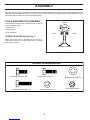 4
4
-
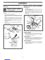 5
5
-
 6
6
-
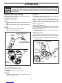 7
7
-
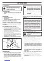 8
8
-
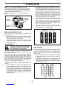 9
9
-
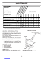 10
10
-
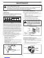 11
11
-
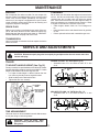 12
12
-
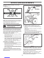 13
13
-
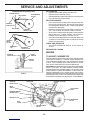 14
14
-
 15
15
-
 16
16
-
 17
17
-
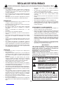 18
18
-
 19
19
-
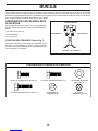 20
20
-
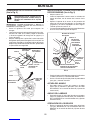 21
21
-
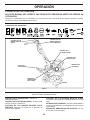 22
22
-
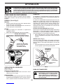 23
23
-
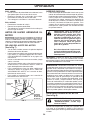 24
24
-
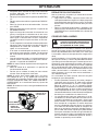 25
25
-
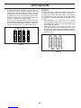 26
26
-
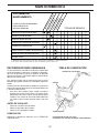 27
27
-
 28
28
-
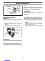 29
29
-
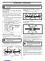 30
30
-
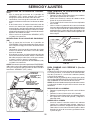 31
31
-
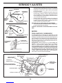 32
32
-
 33
33
-
 34
34
-
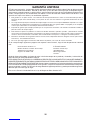 35
35
-
 36
36


Poulan Pro HDF550 Manual de usuario
- Categoría
- Mini cultivadores
- Tipo
- Manual de usuario
en otros idiomas
- English: Poulan Pro HDF550 User manual
Otros documentos
-
Craftsman 29906 - 14 in. Rear Tine Tiller El manual del propietario
-
-
-
-
-
-
-
McCulloch MC550 Manual de usuario
-