

Model Number 60114
Assembly Instructions
Carefully unpack all parts and identify them with parts list before
attempting to assemble.
IMPORTANT: DO NOT TIGHTEN ALL SCREWS UNTIL YOU HAVE
COMPLETED ASSEMBLY.
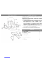
1. Attach BACK CUSHION (F) to SEAT CUSHION (D) by positioning
BACK SUPPORT PLATE (H) with 2 SCREWS (E) and 2
SCREWS (B).
2. Attach left and right ARMRESTS (G) by inserting 4 SCREWS (E)
through each ARMREST (G) and into left and right side of BACK
CUSHION (F) and SEAT CUSHION (D) USING ALLEN KEY (J).
Then place 8 CAPS (I) onto armrest holes.
3. Attach the pre-assembled seat unit to STEEL FRAME (A) by
using 4 SCREWS (B) and 4 FLAT WASHERS (C).
4. Be sure that all the screws are fully tightened before using.
Parts List
Description Quantity
A. STEEL FRAME
1
B. SCREWS( ”X 1-1/4”
6
C. FLAT WASHERS
4
D. SEAT CUSHION
E. SCREWS( ”X 1”
F. BACK CUSHION
G. ARMRESTS (L&R)
H. BACK SUPPROT PLATE
I. CAPS
J. ALLEN KEY
1
10
1
2
1
8
1

Instructions d’assemblage
Instrucciones de ensamble
Déballez soigneusement toutes les pièces et identifiez-les à l’aide de la liste
de matériel avant d’entreprendre l’assemblage.
IMPORTANT : NE SERREZ PAS TOUTES LES VIS TANT QUE
VOUS N’AVEZ PAS COMPLÉTÉ L’ASSEMBLAGE.
Desempaque con cuidado todas las partes e identifíquelas con la lista de
partes antes de comenzar el ensamble.
IMPORTANTE: NO APRIETE LAS TUERCAS Y LOS TORNILLOS
HASTA QUE HAYA TERMINADO EL ENSAMBLE.
1. Attachez le COUSSIN DU DOSSIER (F) au COUSSIN DU SIÈGE (D) en
en installant la PLAQUE DE SUPPORT DU DOSSIER (H) à l’aide de 2
VIS (E) et de 2 VIS (B).
2. Attachez les ACCOUDOIRS (G) de gauche et de droite en insérant 4
VIS (E) à travers chaque ACCOUDOIR (G) et dans le côté gauche et le
côté droit du COUSSIN DU DOSSIER (F) et du COUSSIN DU SIÈGE
(D) en UTILISANT UNE CLÉ ALLEN (J). Ensuite, mettez 8
CAPUCHONS (I) dans les trous des accoudoirs.
3. Attachez l’unité pré-assemblée du siège au CHÂSSIS EN ACIER (A) en
utilisant 4 VIS (B) et 4 RONDELLES PLATES (C).
4. Assurez-vous que toutes les vis sont parfaitement serrées avant l’usage.
1. Una el COJÍN DEL RESPALDO (F) al COJÍN DEL ASIENTO (D)
uniendo la PLACA DE SOPORTE DEL RESPALDO (H) con 2
TORNILLOS (E) y 2 TORNILLOS (B).
2. Una los DESCANSABRAZOS (G) izquierdo y derecho insertando 4
TORNILLOS (E) a través de cada DESCANSABRAZOS (G) y al lado
izquierdo y derecho del COJÍN DEL RESPALDO (F) y del COJÍN DEL
ASIENTO (D) utilizando la LLAVE ALLEN (J). A continuación coloque
las 8 TAPAS (I) en los orificios de los descansabrazos.
3. Inserte la unidad del asiento previamente ensamblada en el MARCO DE
ACERO (A) utilizando 4 TORNILLOS (B) y 4 ARANDELAS PLANAS (C).
4. Asegúrese de que todos los tornillos estén bien apretados antes de
utilizar la silla.
Liste de Matériel
Description Quantité
Lista de partes
Descripción Cantidad
A. CHÂSSIS EN ACIER
1
A. MARCO DE ACERO
1
B. VIS ( ”X 1-1/4”
6
B. TORNILLOS (Ф”X 1-1/4”
6
C. RONDELLES PLATES
4
C. ARANDELAS PLANAS
4
D. COUSSIN DU SIÈGE
E. VIS ( ”X 1”
F. COUSSIN DU DOSSIER
G. ACCOUDOIRS (G&D)
H. PLAQUE DE SUPPORT DU DOSSIER
I. CAPUCHONS
J. CLÉ ALLEN
1
10
1
2
1
8
1
D. COJÍN DEL ASIENTO
E. TORNILLOS (Ф”X 1”
F. COJÍN DEL RESPALDO
G. DESCANSABRAZOS (I&D)
H. PLACA DE SOPORTE DEL RESPALDO
I. TAPAS
J. LLAVE ALLEN
1
10
1
2
1
8
1
-
 1
1
-
 2
2
-
 3
3


en otros idiomas
- français: Lorell 60114
Otros documentos
-
Sharkoon Elbrus 2 Black/Green Manual de usuario
-
Sunrise Medical GTX Manual de usuario
-
-
Quickie Quickie 7RS El manual del propietario
-
-
-
-
Panasonic EP1082 Manual de usuario
-
 The First Years S530 Manual de usuario
-
