
BR-DV3000E
BR-DV3000E
DV VIDEO CASSETTE RECORDER
INSTRUCTION MANUAL
BEDIENUNGSANLEITUNG
MODE D’EMPLOI
ISTRUZIONI PER L’USO
MANUAL DE INSTRUCCIONES
DV VIDEO CASSETTE RECORDER
DV VIDEOKASSETTENREKORDER
ENREGISTREUR A CASSETTE DIGITAL VIDEO
DV VIDEOREGISTRATORE
UNIDAD GRABADORA DE VÍDEO DV
Thank you for purchasing this JVC product.
Before operating this unit, please read the
instructions carefully to unsure the best
possible performance.
LLT0025-001F
© 2008 Victor Company of Japan, Limited
Mini
PROFESSIONAL
SET
MENIU
EJECT
REC PLAY
PAUSE
REW
STOP
FF
DVCAM NTSC
PA L
REC INH.
CH-1/3
CH-2/4
BR-DV3000
A.DUB
OPERATE
INPUT SEL.REMOTE SEL.MIC
SERIAL
WIRELESS
9PIN
LINE
DV
Y/C
LLT0025-001F
EnglishItaliano Español Français Deutsch
BR-DV3000_Cover_Bk_E2_I71 06.8.24, 4:33 PM2

VARIE
–
Caratteristiche tecniche
–
(continua)
䡵 Disegno della dimensione esterna ( in mm )
68
174
260
Mini
PROFESSIONAL
SET
MENIU
EJECT
REC PLAY
PAUSE
REW
STOP
FF
DVCAM NTSC
PAL
REC INH.
CH-1/3
CH-2/4
BR-DV3000
A.DUB
OPERATE
INPUT SEL.REMOTE SEL.MIC
SERIAL
WIRELESS
9PIN
LINE
DV
Y/C
I-71
Supplement
This equipment is in conformity with the provisions and protection requirements of the
corresponding European Directives. This equipment is designed for professional video
appliances and can be used in the following environments:
5
Residential (including both of the location type class 1 and 2 found in IEC 1000-2-5)
5
Commercial and light industrial (including, for example, theatres)
5
Urban outdoors (based on the definition of location type class 6 in IEC 1000-2-5)
This apparatus is designed for rack mounting or is used close to other apparatus.
In order to keep the best performance and furthermore for electromagnetic compatibility
we recommend to use cables not exceeding the following lengths:
The inrush current of this apparatus is 12.1 amperes.
Caution:
5 Where there are strong electromagnetic waves or magnetism, for example near a radio
or TV transmitter, transformer, motor, etc., the picture and sound may be disturbed. In
such a case, please keep the apparatus away from the sources of the disturbance.
Port Cable Length
AUDIO SHIELDED CABLE 10 meters
LINE COAXIAL CABLE 10 meters
Y/C COAXIAL CABLE 10 meters
DV SHIELDED TWIST PAIR CABLE 4 meters
REMOTE TWIST PAIR CABLE 5 meters
E-2
Le caratteristiche del modello e le specifiche tecniche possono essere modificate senza preavviso.
Dear Customer,
This apparatus is in conformance with the valid European directives and standards
regarding electromagnetic compatibility and electrical safety.
European representative of Victor Company of Japan Limited. is:
JVC Technical Services Europe GmbH
Postfach 10 05 04
61145 Friedberg
Germany
BR-DV3000_Cover_Bk_E2_I71 06.8.24, 4:33 PM3

E-3
SAFETY PRECAUTIONS
IMPORTANT (In the United Kingdom)
Mains Supply (AC 230 V
``
``
`)
WARNING – THIS APPARATUS
MUST BE EARTHED
The wires in this mains lead are coloured in
accordance with the following code;
GREEN-and-YELLOW : EARTH
BLUE : NEUTRAL
BROWN : LIVE
As the colours of the wires in the mains lead of
this apparatus may not correspond with the
coloured markings identifying the terminals in
your plug, proceed as follows.
The wire which is coloured GREEN-AND-
YELLOW must be connected to the terminal in
the plug which is marked with the letter E or by
the safety earth symbol or coloured GREEN
or GREEN-AND-YELLOW. The wire which is
coloured BLUE must be connected to the terminal
which is marked with the letter N or which is
coloured BLACK. The wire which is coloured
BROWN must be connected to the terminal
which is marked with the letter L or coloured
RED.
WARNING:
TO REDUCE THE RISK OF FIRE OR
ELECTRIC SHOCK, DO NOT EXPOSE
THIS APPLIANCE TO RAIN OR
MOISTURE.
CAUTION
To prevent electric shock, do not open the
cabinet. No user serviceable parts inside. Refer
servicing to qualified service personnel.
Note:
The rating plate and the safety caution are on
the rear of the unit.
The OPERATE button does not completely
shut off mains power from the unit, but switches
operating current on and off.
WARNING
It should be noted that it may be unlawful to re-
record pre-recorded tapes, records, or discs
without the consent of the owner of copyright in
the sound or video recording, broadcast, or
cable programme and in any literary, dramatic,
musical or artistic work embodied therein.
POWER SYSTEM
Connection to the mains supply
This unit operates on voltage of 220 V to
240 V AC, 50 Hz/60 Hz.
Warning Notice
FOR YOUR SAFETY (Australia)
1. Insert this plug only into effectively earthed
three-pin power outlet.
2. If any doubt exists regarding the earthing,
consult a qualified electrician.
3. Extension cord, if used, must be three-core
correctly wired.
Caution for AC Mains Lead
FOR YOUR SAFETY PLEASE READ THE FOLLOWING TEXT CAREFULLY.
This product is equipped with 2 types of AC cable. One is for continental Europe, etc. and the other one
is only for U.K.
Appropriate mains cable must be used in each local area, since the other type of mains cable is not
suitable.
FOR CONTINENTAL EUROPE, ETC.
Not to be used in the U.K.
FOR U.K. ONLY
If the supplied plug is not suitable for your
socket outlet, it should be cut off and fitted
with an appropriate one.
BR-DV3000_E_p03-49 06.8.24, 1:37 PM3

E-4
Thank you for purchasing our DV
Video Cassette Recorder BR-DV3000.
As this is a DV-format video cassette recorder,
video cassettes with the or logos can
be used with it.
DVCAM cassettes can be recorded in DV for-
mat.
This VTR features dual support for NTSC and PAL.
Certain functions however, are supported by only
one signal system. They are indicated with (NTSC
only) or (PAL only).
● In order to prevent crumpling due to tape
slack, please do not perform important record-
ing within the first and last 2 – 3 minutes run
of the tape.
● Recorded video (music) is meant for personal
entertainment only and must not be used for
other purposes without the prior consent of
the copyright owner.
● Our company shall not guarantee the content
of any recording effort should this VTR fail to
record normally due to defects, either of the
main unit itself or the video cassette tape.
MAIN FEATURES
● DV format
High picture and sound quality by digital tech-
nology.
● Compatible mechanisms for standard/mini
DV cassettes
It records on and plays back DV cassettes of the
standard and mini size. (SP mode only)
DVCAM cassettes can be recorded in DV for-
mat.
A tape recorded with the DVCAM format can be
used only for playback for this VTR.
● Equipped with composite and Y/C input &
output terminal devices.
●
Equipped with DV IN/OUT terminals. (IEEE1394)
It can exchange digital signals with IEEE1394-
compatible devices.
● Dual support for NTSC/PAL
Switch between NTSC or PAL as required. This
makes it easy to work with internationally
sourced material and transfer it to a non-linear
system for editing. You can also record to Stand-
ard DV or Mini DV tape in either NTSC or PAL
system.
● Wireless/wired remote control
It can be controlled with the provided wireless
remote controller or the optional wired remote
controller RM-G30.
● Support for RS-422A interface
It can be used as a player for an editing system
that uses the RS-422A-compatible editing re-
mote controller RM-G820.
● Recording/playback of time codes
● Audio-dubbing (after-recording) function
Audio dubbing at a sampling frequency of 32kHz
is allowed on CH3 and CH4 (except during DV
input).
● Backup recording function
By linking with other DV devices, long-duration
continuous recording is possible.
● Indexed search and blank search function
It can search for indexed signal recorded posi-
tions or unrecorded parts.
● Repeat play function
There are 3 types of repeat function. (INDEX/
VIDEO END/ TAPE END)
● Can be placed in an upright position
With the use of the provided stand, it can be
positioned upright.
BR-DV3000_E_p03-49 06.8.24, 1:37 PM4

E-5
TABLE OF CONTENTS
INTRODUCTION
Precautions .................................................... 6
Daily maintenance and regular inspection ..... 7
Precautions on the use of cleaning tape ........ 8
Cassette tape ................................................. 8
Condensation ................................................. 9
NAMES AND FUNCTIONS OF VARIOUS PARTS
Front panel ................................................... 10
Rear panel .................................................... 14
Wireless remote controller ........................... 16
ON-SCREEN DISPLAY
Regarding on-screen display........................ 18
Status display ............................................... 19
Event display ................................................ 21
Alarm display ................................................ 22
PREPARATION
Provided wireless remote controller ............. 24
Power ........................................................... 26
Selecting the NTSC/PAL signal system ....... 28
OPERATION LOCK mode ............................ 29
Loading/ejecting cassettes ........................... 30
Setting/displaying date and time .................. 31
RECORDING
Connection and setting ................................ 34
Setting time codes ........................................ 36
Recording method ........................................ 38
Audio dubbing .............................................. 39
Backup recording function ............................ 40
Recording using the serial remote terminal ...
41
PLAYBACK
Connection/setting ....................................... 42
Basic playback method ................................ 44
Special playback function ............................. 45
Locate function ............................................. 47
Repeat playback ........................................... 48
Selecting playback audio output ................... 49
EDIT
Using the unit in an editing system .............. 50
MENU SCREEN
Structure of the menu ................................... 53
Setting the menu .......................................... 54
Contents of the menus ................................. 56
OTHERS
Placing the unit in an upright position .......... 65
Warning display ............................................ 66
Troubleshooting ............................................ 68
Checking the hour meter .............................. 69
Specification ................................................. 70
BR-DV3000_E_p03-49 06.8.24, 1:37 PM5

E-6
INTRODUCTION
Precautions
Place of storage and use
Please avoid storing or using this VTR in the fol-
lowing places:
● Extremely hot or cold places beyond the al-
lowable temperature for operation (5˚C – 40˚C).
● Humid or dry places beyond the allowable hu-
midity range for operation (30% –80% RH).
● Dusty or sandy places.
● Places exposed to oil, smoke or steam, such
as the kitchen vicinity.
● Intensely vibrating or unstable places.
● Places prone to condensation.
● Places that generate strong magnetic fields,
e.g., transformer or motor.
● Places near devices that generate electric
waves, e.g., transceiver or mobile phone.
● Places that generate radiation, X-rays or cor-
rosive gases.
Handling the unit
● Please do not place heavy objects on the VTR,
like a monitor or TV.
● Please do not insert foreign objects into the
cassette slot.
● Mind your finger when loading the cassette.
Please be careful not to get your fingers
clamped when loading the cassette to prevent
injury.
● Place this VTR out of reach of young children.
As injury may result from fingers getting
clamped when loading the cassette, please
keep this VTR out of reach of young children.
● Please do not block the ventilation openings.
● Avoid violent shocks to the unit. Do not drop
the unit.
● Please remove the cassette tape from the cas-
sette slot when transporting the unit.
● Please remove the AC adapter to save en-
ergy when the unit is not in use.
Maintaining the unit (Please turn off the
power before performing maintenance
work.)
Please wipe the unit with a soft cloth. Do not wipe
it with thinner or benzene lest the surface melts
or becomes dull. For stubborn stains, wipe first
with a water-diluted neutral detergent and then
wipe dry.
Please use the provided AC adapter to
connect the VTR to a power source.
Use the supplied power cord. Using a
different type or damaged cord may
cause fire or electric shock.
BR-DV3000_E_p03-49 06.8.24, 1:37 PM6

E-7
Daily maintenance and regular inspection
This unit uses consumables or components that will wear off. If a worn-out or deteriorated component
continues to be used, it may cause the unit to break down. To prevent this, please perform daily mainte-
nance using the head-cleaning tape. With the head-cleaning tape alone, however, the entire tape-winding
mechanism cannot be completely cleaned.
Please perform regular maintenance of the components as shown below.
Regular inspection (maintenance)
The tasks of maintenance involved are similar to that of replacing the engine oil or tire of a car.
Depending on the number of usage hours, please clean, inspect or replace the components as
follows:
Number of hours 500H 1000H 1500H 2000H 4000H
Drum assembly (including head)
Head cleaner
Tape guide, roller
Reel disk • tension bands — —
—:Inspection
: Cleaning, inspection and
adjustment
: Cleaning and inspection;
Replacement if necessary
: Replacement
Maintenance necessity and fre-
quency depends on the environ-
ment and usage. The above infor-
mation serves only as a guide.
Usage Time :You can check the drum usage time via the hour meter display.
For details, please refer to page 69, “Checking the hour meter”.
Maintenance consultation :For details on the maintenance plan and fee, please consult with
your nearest JVC-authorized service agent.
Head cleaning
● Recording or playing back with a stained head
will result in block noise or disrupted sound.
Please perform regular head cleaning to main-
tain superior image and sound quality.
● For information on how to use the head cleaning
tape and the relevant precautions, please refer
to page 8, “Precautions on the use of cleaning
tape”.
● If dust adheres on the head, “HEAD CLEANING
REQUIRED!” will be displayed on the monitor
when this unit plays a tape.
Block noise
HEAD CLEANING REQUIRED!
BR-DV3000_E_p03-49 06.8.24, 1:37 PM7

E-8
INTRODUCTION
Precautions on the use of cleaning tape
Please use cleaning tape produced by JVC.
Please follow the instructions below when using the
cleaning tape.
1.
The tape will run for 10 seconds in the PLAY
mode. (Thereafter, it stops automatically and
enters the STOP mode.)
• After loading the cleaning tape, press the PLAY
button.
2.
For a single cleaning session, use it up to 4
times.
3.
Please refer to the following table as a guide for
cleaning.
Operating environment
Low temperature Room temperature High temperature
of the unit 5˚C to 10˚C 10˚C to 35˚C 35˚C to 40˚C
Guide for using 1 to 2 times every 1 to 2 times every 1 to 2 times every
cleaning tape 5 hours 20 to 30 hours 5 hours
Memo:
1. Under low humidity conditions, (10% RH to 30%
RH), please perform head cleaning at intervals
of half of the following stated periods.
2. If M-DV80 is used immediately after cleaning, the
VTR warning (“HEAD CLEANING
REQUIRED!”) may disappear only after the tape
has run for some time.
3. Please use the cleaning tape at room tempera-
ture (10˚C to 35˚C).
4. Instructions for using the cleaning tape are stated
inside its case. The contents may be slightly dif-
ferent from those stated here.
Please follow the instructions in this manual.
Cassette tape
This unit can record onto and playback standard
DV and mini DV cassette tapes (for SP mode only).
Please use the following JVC cassettes with the
or the logos.
Erasure prevention
DV cassettes have a safety slide at the back to
prevent accidental erasure.
● To prevent accidental erasure of important
records, push the slide to the “SAVE” position.
● To record, push the slide to the “REC” posi-
tion.
●
Mini DV cassettes
M-DV63PR0
M-DV60
M-DV30
●
Standard DV cassettes
LA-DV276
LA-DV186
LA-DV124
REC
SAVE
Slide
Memo
● DVCAM cassettes can be recorded in DV format.
Tapes recorded in DVCAM format can be played
(SP Mode).
● M-DV80 cassettes(Mini DV 80min tape) cannot be
used with this unit.
Precautions on the use of tape
● Reverse sides of videotapes cannot be used.
● Please store the tape only after it has been fully rewound, so as to avoid damaging the tape.
● Please store the cassette in places low in humidity, well-ventilated and fungus-proof.
● When a cassette is used repeatedly, noise may increase due to e.g., dropout, etc. hence affecting its
performance. Please do not use dirty or damaged tapes as they will shorten the life span of the
rotation head.
BR-DV3000_E_p03-49 06.8.24, 1:37 PM8

E-9
Condensation
● When this unit is moved from a cold to a warm
place abruptly, the vapor in the warm air will come
into contact with the head drum or the tape
guides. When chilled, the vapor turns into drop-
lets of water. This state is known as condensa-
tion. When condensation occurs, the videotape
will adhere to the head drum or the tape guides
and will be damaged.
● Condensation occurs on this unit in the following
circumstances:
• It is moved abruptly from a cold place to a warm
place.
• It is used in a room immediately after the heater
has been turned on, or when cold breeze from
an air-conditioner blows onto it.
• It is used at a place of high humidity.
● When condensation occurs, the monitor displays
the following warning:
When a cassette tape is loaded, please do not
transport e.g., from an external cold place to a
warm room thereby subjecting the unit to dras-
tic temperature changes.
After moving the unit, please do not use it until
the innards are stabilized.
Head drum
Videotape
To remedy, leave the unit with the power ON and
wait until the WARNING indicator disappears.
● Prevention of condensation
When transporting the BR-DV3000 from a cold
to a warmer place abruptly, first take out the cas-
sette. Then place the BR-DV3000 in a plastic bag
and seal it before transporting the camera.
Leave the BR-DV3000 in the sealed plastic bag
until the camera has the same temperature as
the surroundings. This will prevent condensation.
CONDENSATION ON DRUM
For recording and storing videotapes in the best condition
Observe the following instructions for the best recording and storage of videotapes.
● Take care of the conditions of handling videotapes.
It is recommended that you record and store videotapes in the environment below.
Storage
Recording Short period Long period
(Up to 10 years) (Over 10 years)
Temperature 17°C to 25°C 15°C to 23°C 15°C to 19°C
Humidity 30% to 70% 40% to 55% 25% to 35%
Hourly temperature change Less than 10°C – –
Hourly humidity change Less than 10% – –
● Do not leave the videotapes neglected for a long period.
If videotapes are left wound for a long period of time, it may result in distortion of the tape. Also it may
cause tape-to-tape adhesion (known as blocking). It is recommended that videotapes be unspooled and
rewound once a year for refreshing.
● When tapes are not in use, store them in cases and on end.
Storage cases protect videotapes from humidity, dust and ultraviolet. Keep tapes in cases and do not
store them lying flat. When housed in a horizontal position, pressure from other tapes can cause distor-
tions and deformations of the tape edges.
BR-DV3000_E_p03-49 06.8.24, 1:37 PM9

E-10
Mini
PROFESSIONAL
SET
MENIU
EJECT
REC PLAY
PAUSE
REW
STOP
FF
DVCAM NTSC
PAL
REC INH.
CH-1/3
CH-2/4
BR-DV3000
A.DUB
OPERATE
INPUT SEL.REMOTE SEL.MIC
SERIAL
WIRELESS
9PIN
LINE
DV
Y/C
2
43
1
1
[OPERATE] Operate button/LED
● Press this button to turn on the power and op-
erate the unit. (Operate ON)
Press this button again to turn off the power.
(Operate OFF)
● The OPERATE LED lights up as follows.
Operate ON : the LED lights up green
Operate OFF : the LED lights up red
VTR error : the LED blinks in red
Memo
● When the DC IN MODE item of the SYS-
TEM menu is set to “OPE ON” and power is
supplied to the
1
DC IN terminal located at
the rear panel, the unit goes into the OPER-
ATE ON state even if this button is not
pressed.
● Even when the power has been turned off
with this button, a small amount of electric-
ity will still be channeled into the unit.
Therefore, if the unit is not going to be used
for a long period of time, please remove the
AC adapter to reduce energy consumption.
2
Cassette slot
● Load a cassette into or unload it from the slot.
Please insert a standard DV or a mini DV cas-
sette. (☞ Page 30)
● When the unit is in the OPERATE OFF state
and if a cassette is loaded, it goes into the
ON state.
3
[A. DUB] Audio dubbing button/LED
● Press this button for audio dubbing (after-re-
cording).
For audio dubbing, set the AUDIO MODE item
of the AUDIO/VIDEO menu to “32K”.
Sound produced by the
6
MIC terminal or
the
9
AUDIO IN terminal at the rear panel
(☞ Page 15) is recorded on CH3 and CH4
channels.
● During audio dubbing, the A. DUB LED lights
up red.
● If the INPUT SEL. switch is set at “DV”, audio
dubbing is not possible.
(☞ Page 39, “Audio dubbing”)
4
[INPUT SEL.] Input video signal se-
lection switch
● Select the video signal input with this switch.
Y/C : YC separate video signals from the Y/
C IN terminal
LINE : composite video signals from the LINE
IN terminal
DV :DV signals from the DV IN/OUT termi-
nal (IEEE1394)
Note
During recording, manipulating this switch will
not bring about any effect.
NAMES AND FUNCTIONS
OF VARIOUS PARTS
– Front panel –
BR-DV3000_E_p03-49 06.8.24, 1:37 PM10

E-11
Mini
PROFESSIONAL
SET
MENIU
EJECT
REC PLAY
PAUSE
REW
STOP
FF
DVCAM NTSC
PAL
REC INH.
CH-1/3
CH-2/4
BR-DV3000
A.DUB
OPERATE
INPUT SEL.REMOTE SEL.MIC
SERIAL
WIRELESS
9PIN
LINE
DV
Y/C
56
7
5
[REMOTE SEL.] Remote select
switch
Use this switch to select the remote controller
type.
9 PIN : Select this to use the RS-422A-
compatible editing remote con-
troller (RM-G820) that connects
to the
4
9 PIN REMOTE termi-
nal located at the rear panel.
Please use this unit as a player.
* This setting is valid only when
the REMOTE item of the RE-
MOTE menu is set to ON.
SERIAL : Select this to use the serial re-
mote controller (RM-G30) that
connects to the
3
SERIAL RE-
MOTE terminal located at the
rear panel.
* This setting is valid only when
the REMOTE item of the RE-
MOTE menu is set to ON.
WIRELESS : Select this to use the provided
wireless remote controller.
Memo
●
When 9 PIN or SERIAL is selected, the but-
tons on the unit you wish to render operable
can be selected from the LOCAL FUNCTION
item of the REMOTE menu.
(☞
Page 59)
●
During OPERATION LOCK, this switch will
not be effective.
● Control via the DV IN/OUT terminal is pos-
sible (ie unaffected by the switch setting).
6
[MIC] Microphone input terminal
This is the mini jack for monaural microphone
input. When this terminal is connected to a mi-
crophone, sound input via the AUDIO IN termi-
nal located on the rear panel is not recorded.
Sound from this terminal is recorded on CH1/
CH2 in the RECORD mode and CH3/CH4 in
the AUDIO DUBBING mode.
7
[EJECT] Eject button
● Press this button to eject the cassette.
Memo
It takes about 6 seconds for the cassette to
be ejected.
● If no cassette is loaded and this button is
pressed for at least 2 seconds, a menu will be
displayed on the monitor connected to the
VIDEO LINE OUT or Y/C OUT terminal.
● When the menu is displayed, pressing this
button will resume the usual screen.
(
☞
Page 54, “Setting the menu”)
BR-DV3000_E_p03-49 06.8.24, 1:38 PM11

E-12
NAMES AND FUNCTIONS
OF VARIOUS PARTS
– Front panel – (continued)
8
[REC] Record button/LED
● Hold down this button and press the 9 PLAY
button to start recording. During recording, the
LED lights up red.
● Hold down this button and press the 0 PAUSE
button to pause the recording.
● When this button is pressed during recording,
an index signal is recorded on the tape (valid
when the INDEX WRITE item in the SYSTEM
menu is set to ON).
● When recording is stopped, the time code gen-
erator value can be verified by holding this but-
ton down. If the TC DUPLICATE menu item is
set to AUTO or NON DROP, EE signals of the
DV Input time code and Date/Time can be veri-
fied.
9
[PLAY] Play button/LED
● Press this button to start playing back a tape.
During playback, the LED lights up green.
● When recording is paused, press this button
to resume recording.
● When the menu is displayed, use this button
to select the menu items or setting values.
0
[PAUSE] Pause button/LED
●
During recording, press this button to pause it.
During playback or STOP mode, press this
button to enter the STILL mode. When record-
ing is paused or when the unit is in the STILL
mode, the LED lights up green.
● If this button is pressed simultaneously with
the A.DUB button in the STILL mode, the Au-
dio Dubbing Pause mode will be engaged.
● When the menu is displayed, use this button
to confirm the menu items or setting values.
!
[FF] Fast forward button/LED
● When the unit is in the STOP mode, press
this button to execute fast-forward winding of
the tape.
● When the unit is in the PLAYBACK or STILL
mode, press this button to execute fast-for-
ward playback. The Fast-forward playback
speed changes in the following sequence each
time this button is pressed:
X20¥X5¥X10¥X20...
In the DVCAM mode, the maximum speed is 15X.
● During fast-forward winding or fast-forward
playback, the LED lights up green.
● When the menu is displayed, use this button
to display selected menu items.
When setting up the date, time or time code,
use this button to select the data segment.
@
[STOP] Stop button/LED
● Press this button to stop operation. (of rewind,
playback, etc.)
● When the menu is displayed, use this button
to select the menu items or setting values.
#
[REW] Rewind button/LED
● When the unit is in the STOP mode, press
this button to rewind the tape.
● When the unit is in the PLAYBACK or STILL
mode, press this button to execute reverse
playback. The Reverse playback speed
changes in the following sequence each time
this button is pressed:
X20¥X5¥X10¥X20...
In the DVCAM mode, the maximum speed is 15X.
● During rewinding or reverse playback, the LED
lights up green.
● When the menu is displayed, press this but-
ton to return to the previous screen.
When setting up the date, time or time code,
use this button to select the data segment.
Mini
PROFESSIONAL
SET
MENIU
EJECT
REC PLAY
PAUSE
REW
STOP
FF
DVCAM NTSC
PAL
REC INH.
CH-1/3
CH-2/4
BR-DV3000
A.DUB
OPERATE
INPUT SEL.REMOTE SEL.
MIC
SERIAL
WIRELESS
9PIN
LINE
DV
Y/C
8 9
0
#@
!
BR-DV3000_E_p03-49 06.8.24, 1:38 PM12

E-13
$
Indicator
: When a cassette is loaded, the LED
lights up green. (Likewise when the
unit is in the OPERATE OFF state.)
When a cassette is being loaded
or ejected, the LED blinks.
DVCAM : When the unit plays back a tape re-
corded in the DVCAM format, the
LED lights up green.
NTSC : The LED lights up green in the fol-
lowing cases:
• In the composite video or YC video
signal input mode and the
2
NTSC/PAL switch located at the
rear panel (
☞
Page 14) is set as
“NTSC”.
• A tape recorded with NTSC sig-
nals is played back.
• When NTSC system DV signals
are input while the INPUT SEL.
switch is set at “DV”.
PAL : The LED lights up green in the fol-
lowing cases:
• In the composite video or YC video
signal input mode and the
2
NTSC/PAL switch located at the
rear panel is set as “PAL”.
• A tape recorded with PAL signals
is played back.
• When PAL system DV signals are
input while the INPUT SEL. switch
is set at “DV”.
REC INH : The LED lights up red for about 5
seconds when the unit is set to the
recording mode but fails to record.
E.g. when the rear slide of the cas-
sette is pushed to the “SAVE” posi-
tion.
%
Audio indicator
This indicator allows the user to check the avail-
ability of audio signals.
3 indicators each are available to CH1/3 and
Ch2/4.
^
Sensor for wireless remote controller
When using the provided wireless remote con-
troller, please point it to this sensor.
(
☞
Page 25, “Using the wireless remote con-
troller”)
Mini
PROFESSIONAL
SET
MENIU
EJECT
REC PLAY
PAUSE
REW
STOP
FF
DVCAM NTSC
PAL
REC INH.
CH-1/3
CH-2/4
BR-DV3000
A.DUB
OPERATE
INPUT SEL.REMOTE SEL.
MIC
SERIAL
WIRELESS
9PIN
LINE
DV
Y/C
% $ ^
BR-DV3000_E_p03-49 06.8.24, 1:38 PM13

E-14
NAMES AND FUNCTIONS
OF VARIOUS PARTS
– Rear panel –
1
DC power input terminal (2P)
This is used for DC12V input. It connects the
DC power cord of the provided AC adapter.
Memo
● When power is supplied to this terminal, the
OPERATE indicator located at the front
panel lights up. (The LED lights up red when
the OPERATE indicator is OFF.)
● Setting this unit to OPERATE ON, OPER-
ATE OFF or PLAY mode when the power is
supplied to this terminal can be done by mak-
ing the appropriate selections from the DC
IN MODE item in the SYSTEM menu.
2
[NTSC/PAL] NTSC/PAL signal se-
lection switch
Use this switch to select NTSC or PAL as the
signal system. Use it to make a selection when
composite video signals or YC separate video
signals are input.
NTSC : Use this setting for NTSC signal input.
The NTSC indicator on the front panel
lights up.
PAL : Use this setting for PAL signal input.
The PAL indicator on the front panel
lights up.
Memo
● For playback or DV signal input, signals are
determined automatically and not affected
by the status of this switch.
● Please turn the unit to OPERATE OFF be-
fore using this switch. If switching is per-
formed when the VTR is in the OPERATE
ON mode, the VTR will automatically go into
the OFF mode before engaging the ON
mode.
● It cannot be used for NTSC/PAL conversion.
DV IN/OUT
AUDIO VIDEO
LINE
Y/C
CH 1/3 CH 2/4
INOUT
REMOTE
SERIAL
9PIN
NTSC/PAL
NTSC PAL
DC12V
4 3 2
1
3
[SERIAL REMOTE] serial remote
terminal (mini jack)
Connect this terminal to the serial remote con-
troller RM-G30, which is available separately.
To control this unit via this terminal, please set
it up as follows.
● Set the REMOTE item of the REMOTE
menu to “ON”.
● Set the REMOTE SEL. switch on the front
panel to “SERIAL”.
Memo
To use this terminal as the FOOT switch in-
put terminal, please set the FOOT SW item
of the REMOTE (2/2) menu. (
☞
Page 60)
4
[9 PIN REMOTE] 9-pin remote ter-
minal (D-SUB)
Use this terminal to connect to the RS-422A-
compatible editing remote controller (RM-G820).
Please use this unit as a player. To control this
unit with this terminal, please set it up as fol-
lows:
● Set the REMOTE item of the REMOTE
menu to “ON”.
● Set the REMOTE SEL. switch on the front
panel to “9 PIN”.
BR-DV3000_E_p03-49 06.8.24, 1:38 PM14

E-15
DV IN/OUT
AUDIO VIDEO
LINE
Y/C
CH 1/3 CH 2/4
INOUT
REMOTE
SERIAL
9PIN
NTSC/PAL
NTSC PAL
DC12V
!65
87
9
0
5
[VIDEO Y/C IN] Video Y/C input
terminal (4P)
This is the input terminal for YC separate video signals.
● To input video signals from this terminal,
set the INPUT SEL. switch on the front panel
to “Y/C”.
● When Wide discriminating signals are in-
put, ID signals for Wide discriminating sig-
nals are recorded.
6
[VIDEO LINE IN] Video line input
terminal (RCA)
This is the input terminal for composite video
signals.
● To input video signals from this terminal,
set the INPUT SEL. switch on the front panel
to “LINE”.
7
[VIDEO Y/C OUT] Video Y/C output
terminal (4P)
This is the output terminal for YC separate video
signals.
When tapes recorded with Wide discriminating
signals are played, ID signals for discriminating
signals are output.
8
[VIDEO LINE OUT] Video line out-
put terminal (RCA)
This is the output terminal for composite video signals.
Memo
● Besides video signals, the following signals from
the VIDEO Y/C OUT terminal and VIDEO LINE
OUT terminal are displayed on-screen.
• Menu screen signals
• Character display of date, time or operation
modes (Status screen)
By pressing the DISPLAY button on the wireless
remote controller or by setting the DISPLAY item
in the DISPLAY menu, the user can choose to
turn the status display on/off.
● The SETUP item of the AUDIO/VIDEO menu can
be set to determine whether setup will be added
to the signals of VIDEO Y/C OUT terminal and
VIDEO LINE OUT terminal. (NTSC only)
9
[AUDIO IN] Audio input terminal
(RCA2)
This is the audio signal (analogue) input termi-
nal.
For audio dubbing, sounds from the CH1/3 ter-
minal are recorded on the CH3 channel while
those from the CH2/4 channel are recorded on
the CH4 channel.
Memo
● When the MIC terminal on the front panel is con-
nected to a microphone, sounds from this termi-
nal will not be recorded.
0
[AUDIO OUT] Audio output terminal
(RCA2)
This is the audio signal (analogue) output ter-
minal.
Memo
● The audio channel to play back tapes recorded in
the 32K mode can be selected with the OUT SE-
LECT button on the wireless remote controller or
by setting the AUDIO OUT SEL. item of the AU-
DIO/VIDEO menu.
● The output level of the playback audio can be se-
lected with the OUT LEVEL button of the wireless
remote controller or by setting the AUDIO OUT
LEVEL item of the AUDIO/VIDEO menu (NORMAL
or ATT).
!
[DV IN/OUT] DV input/output terminal
This is the input/output terminal for digital sig-
nals of IEEE1394 standard. It is connected to
video devices with DV terminals.
● To input signals from this terminal, please set
the INPUT SEL. switch on the front panel to
“DV”.
● Signals from this terminal are output regard-
less of the INPUT SEL. switch setting.
BR-DV3000_E_p03-49 06.8.24, 1:38 PM15

E-16
NAMES AND FUNCTIONS
OF VARIOUS PARTS
–
Wireless remote controller
–
DISPLAY
BARS
MENU SEARCH+
SEARCH–
A.DUB
F.REV
INDEX– INDEX+
PLAY
STOP
REMOTE CONTROL UNIT
RM-G3000
REW FF
PAUSE
SET
BLANK
STILL
MODE
AUDIO
MUTING
OUT SEL.
OUT LEV.
REC
F.ADV
1
6
7
8
@
#
%
2
3
9
0
!
$
^
45
SET
button
&
1
[OPERATE] button f
Press this button to turn on the power of the
unit. (OPERATE ON)
Press this button again to turn off the power.
(OPERATE OFF)
2
[DISPLAY] button
Use this button to turn on/off, the on-screen (e.g.
status screen) display on the monitor connected
to the VIDEO LINE OUT terminal and Y/C OUT
terminal. Each time this button is pressed, the
display mode changes in the following se-
quence: ON (always display) ¥ AUTO (display
when switching mode) ¥ OFF.
(
☞
Page 18, “On-screen display”)
3
[BARS] button
When this button is pressed in the Stop or REC-
Pause mode, the color bar of the built in signal
generator will be output. When it is pressed
again, the screen returns to the usual display.
During DV signal input, the color bar will not be
output.
Note
Please do not use it as the standard signal
because the signals are simplified.
4
[STILL MODE] button
Use this button to select images in the STILL
mode.
When the unit is in the STILL mode, press this
button to toggle images in the following se-
quence.
Field image (1st/2nd alternate still) ¥ 1st field
image ¥ 2nd field image ¥ frame image
5
[BLANK] button
When the unit enters the STOP mode, press
this button to begin a blank search. Once it finds
a blank part of the tape, it will enter the STILL
mode. (
☞
Page 47)
6
[AUDIO MUTING] button
During playback, press this button to mute the
audio output. Press this button again to re-en-
able audio output.
7
[AUDIO OUT SEL.] button
When playing back tapes recorded in the 32K
mode, use this button to select the audio chan-
nel that allows output from the AUDIO OUT ter-
minal.
CH1/2 ¥ CH3/4 ¥ MIX
8
[AUDIO OUT LEV.] button
Use this button to switch the standard level
of the playback or EE audio output (NOR-
MAL or ATT). When it is set to ATT, the out-
put level is reduced by 8dB.
9
Buttons related to menu setting and
variable speed playback
[MENU] button
When the unit enters the STOP mode and
this button is pressed, a menu will be dis-
played on the monitor connected to the
VIDEO LINE OUT or Y/C OUT terminal.
When the menu is displayed, press this but-
ton to return to the usual screen display.
[SEARCH+] /
button
• During playback, STILL mode or variable
speed playback in the forward direction,
press this button to speed up playback.
• During reverse playback or variable speed
playback in the reverse direction, press this
button to slow down the playback speed.
(
☞
page 46)
• When the menu is displayed, use this but-
ton to select the menu items or setting val-
ues.
BR-DV3000_E_p03-49 06.8.24, 1:38 PM16

E-17
[SEARCH–] /
button
• During playback, STILL mode or variable
speed playback in the forward direction,
press this button to slow down the playback
speed.
• During reverse playback or variable speed
playback in the reverse direction, press this
button to speed up the playback speed.
(
☞
page 46)
• When the menu is displayed, use this but-
ton to select the menu items or setting val-
ues.
[
P
] /
button
• During reverse payback/ variable-speed
playback, press this button to execute for-
ward playback.
• When the menu is displayed, use this but-
ton to display the selected menu items.
During date/time or time code setup, press
this button to move the cursor to the right.
[
p
] /
button
• During forward playback/ variable-speed
playback, press this button to execute re-
verse playback.
• When the menu is displayed, press this
button to display the previous menu.
During date/time or time code setup, press
this button to move the cursor to the left.
SET button
During menu display, press this button to
confirm the menu items or setting values.
0
[A. DUB] button
Press this button to perform audio dubbing (af-
ter-recording). (
☞
Page 39, “Audio dubbing”)
!
[PAUSE] button
During recording, audio dubbing or playback,
press this button to pause recording or enter
the STILL mode.
If this button is pressed in the STOP mode, the
STILL mode will be engaged.
@
[REC] button
● Hold down this button and press the PLAY
button to begin recording.
● During recording, press this button to record
an index on the tape. (when the INDEX WRITE
item of the SYSTEM menu is set to ON)
● When the unit enters the STOP mode, hold-
ing this button down will enable you to check
the value of the time code generator.
#
[F. ADV] button
Each time this button is pressed in the STILL
mode, the image is advanced one frame. When
holding down this button, the image is advanced
continuously frame by frame.
$
[F. REV] button
Each time this button is pressed in the STILL
mode, the image is reversed one frame. When
holding down this button, the image is reversed
continuously frame by frame.
Memo
The image of frame advance playback or frame
reverse playback can be selected with the STL/
F.ADV MODE item of the SYSTEM menu or the
STILL MODE button on the wireless remote con-
troller.
%
[INDEX+] button
Press this button to perform an index search in
the forward direction.
(☞
Page 47)
^
[INDEX–] button
Press this button to perform an index search in
the reverse direction.
(☞
Page 47)
&
Operation buttons
[PLAY] (
) button
• Press this button to play back.
• Press this button to resume recording from
the PAUSE mode.
[FF] (
) button
• Press this button to fast-forward the tape
when the unit is in the STOP mode.
• Press this button to execute fast-forward
playback in the PLAY or STILL mode.
[REW] (
) button
• Press this button to rewind the tape when
the unit is in the STOP mode.
• Press this button to execute reverse play-
back in the PLAY or STILL mode.
[STOP] ( ) button
• Press this button to stop the tape.
BR-DV3000_E_p03-49 06.8.24, 1:38 PM17

E-18
ON-SCREEN DISPLAY
–
Regarding on-screen display
–
Besides E-E images and playback images, the monitor connected to the VIDEO LINE OUT terminal and Y/
C OUT terminal provides the following on-screen information.
DISPLAY
BARS
MENU SEARCH+
SEARCH–
A.DUB PAUSE
SET
BLANK
STILL
MODE
AUDIO
MUTING
OUT SEL.
OUT LEV.
REC
MENU
button
DISPLAY
button
–––DISPLAY[1/2]–––
DIPLAY ON
COUNT ER POS I . LO
W
ER - R
TIME CODE ON
VTR MODE ON
TAPE REMA IN OFF
TIME DATE DATE+TM
AUD I O I NFO . CH+RATE
NEXT PAGE
PAGE BACK
Set at ON
or AUTO
Wireless remote controller
DISPLAY (1/2) menu
On-screen display Contents Method
Status display
Event display
Alarm display
It displays the setting status of date/
time, time code and VTR operation
mode.
It displays the operating status of the
blank search, index recording/search,
or the wireless remote control.
It displays alarm messages upon op-
eration errors or if the unit is in a poor
state for operation.
Main unit
Set the DISPLAY item of the DISPLAY
(1/2) menu as follows:
ON : Always display. Depending
on the items, Event and
Alarm displays are shown for
about 3 seconds.
AUTO : It displays for about 4 sec-
onds after switching between
modes.
OFF : No on-screen display.
Remote controller
The display can be turned ON/OFF
with the DISPLAY button. Each time
the DISPLAY button is pressed, the
display mode changes in the follow-
ing sequence: ON (Always display)
¥AUTO ¥ OFF.
*The settings for the DISPLAY menu
items will also change accordingly.
Warning display It displays warning messages with er-
ror codes in the event of VTR anoma-
lies. (
☞
Page 66)
It is displayed automatically when
anomalies happen.
Menu display It displays the menu setting screen.
(
☞
Page 53)
Main unit
If no cassette is loaded and the EJECT
button is pressed for at least 2 sec-
onds, the menu will be displayed.
Remote controller
If the unit is in the STOP mode and
the MENU button is pressed, the menu
screen will be displayed.
BR-DV3000_E_p03-49 06.8.24, 1:38 PM18

E-19
ON-SCREEN DISPLAY
–
Status display
–
Status display: It displays the current settings and operating status.
32K CH–1/2
SP
000
min
10/ 10/ 02 STANDBY
-
OFF
12: 00: 00 TCR 02:00:00:00
1
2
No. Item Content
1
Sampling frequency/audio
output CH
• Sampling frequency
During recording, the setting value of the AUDIO MODE item
of the AUDIO/VIDEO menu is displayed (32K or 48K).
During playback, the sampling frequency of the sound re-
corded on the tape is displayed (32K, 48K, 44.1K).
During DV signal input, the sampling frequency of the sound
input is displayed.
• A.LOCK
Lights up when the video and audio sampling clocks (at
48kHz) are synchronized in the PLAY mode.
Lights up in the RECORDING mode and EE mode.
Does not light up when the sampling rate is 32kHz or 44.1
kHz.
•Audio output channel
During recording, the audio channel recorded on the tape is
displayed.
During playback, the audio channel output from the AUDIO
OUT terminal is displayed (CH1/2, CH3/4, MIX). (only in 32K
mode)
• The AUDIO INFO. item of the DISPLAY menu can be set to
activate/deactivate the display.
Memo
If the time code display po-
sition is set to the upper left,
this item will be displayed on
the lower right.
2
Date/time
• It displays the date (DD/MM/YY) and time (HR:MM:SS).
• When the unit is in the RECORDING or STOP mode, it dis-
plays the data of the built-in clock.
• During playback, fast forward or rewind, the data recorded
on the tape is displayed.
• During DV signal recording, the data from the DV terminal is
displayed. If the REC button is pressed in the STOP mode,
the input data from the DV terminal will be displayed.
• The style for displaying the date and time can be selected
from the DATE STYLE and TIME STYLE items of the DIS-
PLAY menu.
• The TIME/DATE setting of the DISPLAY menu can be set to
turn on/off the date and time display or to select the style.
• When the data/time is not set, “– –” will be displayed.
If a tape with no date and time data is played, "– –" will be
displayed.
Memo
If the display position of the
time code is set to the lower
left, this item will be dis-
played on the lower right.
BR-DV3000_E_p03-49 06.8.24, 1:38 PM19

E-20
ON-SCREEN DISPLAY
–
Status display
–
(continued)
No. Item Content
3
Time code
• It displays the time codes (hour, minute, second and frame).
During playback, the time codes recorded on the tape are
displayed.
TCR : time code reader data
TCG : time code generator data
DTCG : time code data input from a DV IN terminal
• The symbols for the second and frame differ according to the
framing modes. (NTSC only)
00 : 00 : 00 : 00
¥
dot (.) is used for a dropped frame.
colon (:) is used for a non-dropped
frame.
• The time code display position can be set via the COUNTER
POSI. item of the DISPLAY menu.
• The TIME CODE item can be set to turn on/off the time code
display.
• The user’s bit is not displayed.
4
VTR operation mode
It displays the VTR operation modes, including:
PLAY, EJECT, FF, REW, STANDBY-ON, STANDBY-OFF, STILL,
REC, REC PAUSE, A. DUB, A. DUB PAUSE, SHTL (shuttle
search), JOG (F.ADV, R.ADV), BLANK SRH (blank search),
NO CASSETTE (cassette not loaded), OPERATE OFF.
When SHTL or JOG is displayed, the speed will also be dis-
played at the same time.
• The VTR MODE item of the DISPLAY menu can be set to
turn on/off the VTR operation mode display.
Memo
If the display position of the
time code is set to the upper
right, this item will be dis-
played on the lower right.
32K CH–1/2
SP
000
min
10/ 10/ 02 STANDBY
-
OFF
12: 00: 00 TCR 02:00:00:00
5
4
3
5
Remaining tape
It displays the remaining tape duration (minutes).
If it is not identified, “ – – – ” is displayed.
• The TAPE REMAIN item in the DISPLAY menu can be set to
turn on/off the remaining tape duration display.
• The SP display disappears when the DVCAM cassette is
being played back.
• Please use the remaining tape time as a gauge.
BR-DV3000_E_p03-49 06.8.24, 1:38 PM20

E-21
ON-SCREEN DISPLAY
–
Event display
–
Event display : When a specific function is in activation or when the operation status is
changed with the remote controller, etc, the events will be displayed at
the positions shown below.
32K CH–1/2
SP
000
min
BLANK SEARCH
INDEX DETECTED
10/ 10/ 02 STANDBY
-
OFF
12: 00: 00 TCR 02:00:00:00
A
B
Display at position A
...Operation in progress
Display Contents
Display Contents
AUDIO OUT
LEVEL NORM
AUDIO OUT
LEVEL ATT
AUDIO OUT CH-1/2
AUDIO OUT CH-3/4
AUDIO OUT MIX
DISPLAY ON
DISPLAY AUTO
DISPLAY OFF
FIELD STEP
1ST FIELD STILL
2ND FIELD STILL
FRAME STILL
The standard level of the
playback or EE audio level is
set to NORMAL or ATT with
the remote controller.
The playback audio channel is
set to CH1/2, CH3/4 or MIX
with the remote controller.
The on-screen display is
turned on with the remote
controller.
The on-screen display is set
to AUTO with the remote
controller. In the AUTO
mode, the on-screen display
is shown for about 4 seconds
between mode switches.
The on-screen display is set
to OFF with the remote con-
troller.
Field by field advance play-
back is selected with the re-
mote controller.
When still or frame advance
playback is selected with the
remote controller, the type of
still image is displayed.
• 1st FIELD STILL
• 2nd FIELD STILL
• FRAME STILL
BLANK SEARCH
INDEX + 1
INDEX MARK
Blank search in progress.
Index search in progress.
The number indicates the
index search position.
When an index is written on
the tape during recording.
Display at position B
...Display for about 3 seconds
Display Contents
INDEX DETECTED
VIDEO END
DETECTED
AUDIO MUTING
ON
AUDIO MUTING
OFF
Index is found during an in-
dex repeat operation.
Video end is found during a
video end repeat operation.
Audio is muted with the re-
mote controller.
Audio is de-muted with the
remote controller.
BR-DV3000_E_p03-49 06.8.24, 1:38 PM21

E-22
ON-SCREEN DISPLAY
–
Alarm display
–
Alarm display : Alarm messages are displayed as shown below, when an operation
error has occurred or when the unit is in a poor condition for operation.
E.g., dirty head.
Display Contents
LOW VOLTAGE
HEAD CLEANING
REQUIRED!
OVERHEATING!
The voltage of the DC input power is low. Continued operation will bring the unit to the
Operate OFF mode.
The video head is dirty. Please clean it with the dedicated head-cleaning tape.
(
☞
Page 8)
If the head is clogged, it will be detected in the PLAYBACK mode and displayed.
When the unit enters the STOP mode or the cassette is ejected, the display goes off.
The temperature inside the unit has exceeded the regulated value.
Please disconnect the power and place the unit in a cool place.
If this message is displayed again, damage may have occurred. Please consult with
your JVC-authorized service agent.
32K CH–1/2
SP
000
min
HEAD CLEANING REQUIRED!
NO DV S I GNAL
1 0/10/02 STANDBY
-
OFF
12: 00: 00 TCR 02:00:00:00
A
B
Display at position A : Displays which show the state of the unit (and which are not set
via the DISPLAY mode) continues to be displayed here until the
conditions are rectified.
Display Contents
INVALID TAPE!
LP TAPE!
NO DV SIGNAL
Data tapes for PC use or DVC PRO tapes has been inserted.
The cassette will be ejected.
The user attempts to play back a tape recorded in the LP mode.
This unit cannot record or play in the LP mode.
The user attempts to record without DV signal input.
Display at position B : Messages indicating operation errors are displayed for about 3
seconds.
They are displayed when the DISPLAY mode is ON or AUTO.
BR-DV3000_E_p03-49 06.8.24, 1:38 PM22

E-23
Display Contents
COPY INHIBIT
REC INHIBIT
A. DUB INHIBIT
(REC TAB)
A. DUB INHIBIT
(48K)
A. DUB INHIBIT
(LP)
A. DUB INHIBIT
(BLANK)
A. DUB INHIBIT
(DV)
A. DUB INHIBIT
(NTSC/PAL)
A. DUB INHIBIT
(DVCAM)
OPERATION
LOCK
The user attempts to record signals protected with the copy guard.
The user attempts to record on a write protected cassette tape.
(The rear slide is pushed to “SAVE”.)
The user attempts to perform audio dubbing on a write protected cassette tape.
(The rear slide is pushed to “SAVE”.)
This message is displayed when audio dubbing is attempted under the following con-
ditions:
• The AUDIO MODE item of the AUDIO/VIDEO menu is set to 48K.
• The tape is recorded with a sample frequency of 48kHz.
The user attempts to perform audio dubbing on a tape recorded in the LP mode.
The user attempts to perform audio dubbing on a blank tape.
The user attempts to perform audio dubbing during DV signal input. (The INPUT SEL.
switch is set to “DV”)
This message is displayed when the signal system is changed during audio dubbing
(NTSC or PAL).
The user attempts to perform audio dubbing on a DVCAM format tape.
This message is displayed when a button on the unit is pressed while the OPERA-
TION LOCK function is engaged (ie, the OPERATION item of the SYSTEM (2/2) menu
is set as “ON”).
Warning display : When anomalies occur in the VTR, warning messages with error
codes will be displayed.
32K CH–1/2
SP
000
min
W
ARNING 7001
DRUM MOTOR FA I LURE
10/ 10/ 02 STANDBY
-
OFF
12: 00: 00 TCR 02:00:00:00
Warning display
For details, please
refer to page 66,
“Warning Display”.
BR-DV3000_E_p03-49 06.8.24, 1:38 PM23

E-24
PREPARATION
–
Provided wireless remote controller
–
Loading the batteries
Before using the wireless remote controller, please load 2 batteries (AA/R6) in.
1
Lift up the cover
of the battery
compartment.
2
Load in 2 batteries
(AA/R6).
• Please insert the · pole
in first.
3
Close the cover.
Battery
compartment
cover
+
-
-
+
Memo
Guide on battery replacement.
When the operable distance of the remote
controller is decreased, the batteries have
become exhausted. Please replace them.
Guide for replacement: Approx 3 months
based on average usage of 1000 times a day.
When replacing the batteries
• Please use AA/R6 batteries.
• Please use 2 new batteries.
(Do not mix new and old batteries.)
• Please load the batteries correctly accord-
ing to the ª and · signs.
• Please read the precautions printed on the
batteries.
Precautions on the use of battery
• The provided batteries are for confirmation
of operation.
• If the remote controller is not to be used for
a long period of time, please remove the
batteries from the compartment.
• If the remote controller does not work as
expected, please remove the batteries and
reload them after 5 minutes.
Note
If fluid leaks from the battery, please wipe the
battery compartment thoroughly.
If the fluid comes into contact with your body,
please rinse the affected parts with water thor-
oughly.
BR-DV3000_E_p03-49 06.8.24, 1:38 PM24

E-25
Using the wireless remote controller
Maximum distance to the sensor
of the unit : 6m
Angle : within 30˚
Mini
PROFESSIONAL
SET
MENIU
EJECT
REC PLAY
PAUSE
REW
STOP
FF
DVCAM NTSC
PA L
REC INH.
CH-1/3
CH-2/4
BR-DV3000
A.DUB
OPERATE
INPUT SEL.REMOTE SEL.
MIC
SERIAL
WIRELESS
9PIN
LINE
DV
Y/C
Sensor for the wireless remote controller
Before using the wireless remote controller,
please set the REMOTE SEL. switch to
“WIRELESS”.
Operable scope of the wireless remote controller
Mini
PROFESSIONAL
SET
MENIU
EJECT
REC PLAY
PAUSE
REW
STOP
FF
DVCAM NTSC
PAL
REC INH.
CH-1/3
CH-2/4
BR-DV3000
A.DUB
OPERATE
INPUT SEL.REMOTE SEL.
MIC
SERIAL
WIRELESS
9PIN
LINE
DV
Y/C
Sensor for the wireless remote controller
About 30˚
About 30˚
Not further than 6m
Notes
• The remote controller will hardly work if there are obstructive objects between the remote control
sensor of the main unit and the remote controller.
• The remote controller will hardly work when sunlight or strong light shines directly on the remote
control sensor of the main unit.
• Do not press the buttons on the main unit and the remote controller simultaneously for this may
cause malfunction.
Caution on using the wireless remote controller
When more than 2 VTRs are being individually operated in the same place, please ensure that the
front panel REMOTE SEL. switches of all VTRs except the one to be manipulated, are NOT set at
“WIRELESS”.
BR-DV3000_E_p03-49 06.8.24, 1:38 PM25

E-26
PREPARATION
– Power –
Connect the provided AC adapter to the main unit.
DV IN/OUT
AUDIO VIDEO
LINE
Y/C
CH 1/3 CH 2/4
INOUT
REMOTE
SERIAL
9PIN
NTSC/PAL
NTSC PAL
DC12V
AC
Provided power
cord
DC cord
Screw
Clamp
DC IN terminal
Provided AC adapter
Mini
PROFESSIONAL
DVCAM NTSC
PA L
REC INH.
CH-1/3
CH-2/4
BR-DV3000
A.DUB
OPERATE
INPUT SEL.REMOTE SEL.MIC
SERIAL
WIRELESS
9PIN
LINE
DV
Y/C
OPERATE indicator
OPERATE button
1.
Connect the DC cord of the AC adapter
to the DC IN terminal of the main unit.
2.
To prevent accidental disconnection of
the DC cord, fasten the DC cord with a
clamp.
1Remove 1 screw followed by the clamp.
2Insert the DC cord into the clamp and fasten
the clamp unto the main unit.
3.
Connect the provided power cord to the
AC IN terminal of the AC adapter.
4.
Connect the power cord to the power
socket.
•Power is channeled into the unit and the OP-
ERATE indicator lights up red.
(OPERATE OFF mode)
• If the DC IN MODE item of the SYSTEM (2/
2) menu is set to “OPE ON” or “PLAY”, the
OPERATE indicator will light up green.
(OPERATE ON mode)
If it is set to PLAY, the VTR will automatically
start to play the loaded tape.
Memo
•Even in the OPERATE OFF mode, a small
amount of electricity will still flow into the unit.
• When the unit is in the OPERATE OFF
mode, no operation can be performed ex-
cept that of the OPERATE buttons(on the
main unit and the remote controller) and
cassette loading/ejecting.
Notes
• Please supply power to the unit via the provided AC adapter. Do
not use other power sources.
• During recording or playback, please do not unplug the DC or
power cord.
• When the supply voltage is low, the “LOW VOLTAGE” alarm mes-
sage will be displayed. (
☞
Page 66)
LOW VOLTAGE
Alarm message
Connecting to the AC adapter
BR-DV3000_E_p03-49 06.8.24, 1:38 PM26

E-27
Switching on the power
Mini
PROFESSIONAL
REC PL
AY
REW
STO
DVCAM NTSC
PA L
REC INH.
CH-1/3
CH-2/4
BR-DV3000
A.DUB
OPERATE
INPUT SEL.REMOTE SEL.MIC
SERIAL
WIRELESS
9PIN
LINE
DV
Y/C
OPERATE indicator
OPERATE button
DISPLAY
BARS
MENU SEARCH+
SEARCH–
A.DUB
F.REV
INDEX– INDEX+
PLAY
STOP
REMOTE CONTROL UNIT
RM-G3000
REW FF
PAUSE
SET
BLANK
STILL
MODE
AUDIO
MUTING
OUT SEL.
OUT LEV.
REC
F.ADV
Turning off the power
Stop all operational activities of the unit.
1.
Press the OPERATE button on the unit or the remote controller.
• The unit will enter the OPERATE OFF mode and the OPERATE indicator will light up red.
2.
If the unit is not to be used for a long period of time, please unplug the AC adapter.
•To disconnect the AC adapter, please unplug the power cord from the socket first.
When the unit is in the OPERATE OFF
mode (the OPERATE indicator lights
up red), press the OPERATE button on
the unit or the remote controller.
• The power is turned on and the OPERATE in-
dicator lights up green. The unit is now ready
for operation. (OPERATE ON mode)
Memo
• Once a cassette has been loaded in the OP-
ERATE OFF mode, power will be turned on
and the OPERATE ON mode will be engaged.
• The remote controller is only effective when
the REMOTE SEL. switch is set to “WIRE-
LESS”.
Note
• After pressing the OPERATE button and turn-
ing on the power, if the LED blinks in green or
the “UNPLUG MAIN POWER, PLUG BACK
IN AFTER A WHILE” is displayed on the moni-
tor, please unplug the power cord from the
outlet and then wait for some time before plug-
ging it in again.
BR-DV3000_E_p03-49 06.8.24, 1:38 PM27

E-28
PREPARATION
–
Selecting the NTSC/PAL signal system
–
This unit supports both the NTSC and PAL signal system.
Before inputting analogue signals (composite or YC separate video signals), please select the
signal system.
Mini
PROFESSIONAL
REC PLAY
REW
STOP
DVCAM NTSC
PA L
REC INH.
CH-1/3
CH-2/4
BR-DV3000
A.DUB
OPERATE
INPUT SEL.REMOTE SEL.MIC
SERIAL
WIRELESS
9PIN
LINE
DV
Y/C
NTSC
indicator
OPERATE
button
PAL
indicator
VIDEO
LINE
Y/C
2
/4
INOUT
REMOTE
SERIAL
9PIN
NTSC/PAL
NTSC PAL
DC12V
NTSC/PAL switch
Steps
1.
Set the unit to the OPERATE OFF mode.
2.
Please select the signal system with the NTSC/PAL switch on the rear panel.
3.
Press the OPERATE button to engage the OPERATE ON mode. Either the NTSC or
PAL indicator on the front will then light up, according to the NTSC/PAL switch set-
ting.
Memo
• In the playback mode, the signal system of the tape is automatically identified, regardless of the
NTSC/PAL switch setting.
• During DV signal input, the signal system of the input signal is automatically identified, regardless
of the NTSC/PAL switch setting.
• This unit is equipped with a function to automatically detect the signal system of the cassette being
played back or the signal being received at the DV input connector. However, this function may not
operate correctly in some instances.
To ensure the correct system selection, it is recommended that you match the rear panel’s NTSC/
PAL switch to the signal system of the input signal or playback tape.
• When the unit enters the STOP mode, the NTSC/PAL switch setting will be engaged.
• If a tape recorded in both NTSC & PAL signal systems is played, the video, audio or time code may
be distorted at the position where the signal system is switched.
• When the signal system of the tape and the NTSC/PAL setting differ, video and sound output will be
upset for about 5 seconds after playback starts or stops.
• NTSC/PAL signal system conversion is not possible.
BR-DV3000_E_p03-49 06.8.24, 1:38 PM28

E-29
PREPARATION
– OPERATION LOCK mode –
This unit comes with an operation lock function to prevent unintended, erroneous operation.
In the OPERATE LOCK mode, the buttons on the main unit and the slide switch are invalid.
However, OPERATE ON and MENU operations are still possible.
–––SYSTEM[2/ 2 ] –––
DC I N MODE OPE OF F
OPERAT I ON LOCK ON
PAGE BACK
SYSTEM (2/2) menu
–––SYSTEM[2/ 2 ] –––
DC I N MODE OPE OF F
OPERAT I ON LOCK ON
PAGE BACK
OPERATION LOCK
To set the unit to the OPERATION LOCK mode:
Set the OPERATION LOCK item of the SYSTEM (2/2) menu to
“ON”. (
☞
Page 54, “Setting the Menu”)
● In the OPERATION LOCK mode, when a button on the unit is
pressed, “OPERATION LOCK” will be displayed on the monitor
for about 3 seconds.
To turn off the OPERATION LOCK mode:
Set the OPERATE LOCK item of the SYSTEM(2/2) menu to “OFF”.
If the EJECT button is pressed while the VTR is in the OPERATE
LOCK mode, "OPERATION LOCK" will be displayed. However,
pressing the EJECT mode button persistently will eventually bring
on the MENU screen.
BR-DV3000_E_p03-49 06.8.24, 1:38 PM29

E-30
PREPARATION
–
Loading/ejecting cassettes
–
Please use standard DV cassettes or mini DV cassettes.
Loading the cassette
1.
Check the cassette.
• Set the rear slide.
Push it to “REC” for recording or “SAVE” to prevent its contents
from being erased accidentally.
• Check that the tape is not slackened.
Use an object, such as a clip, to turn the reel in the direction of
the arrow. If the tape is taut, the reel will not rotate.
2.
Check that the cassette indicator on the unit is unlit.
When a cassette is loaded, the cassette indicator will lit up.
3.
Load the cassette.
•For the standard DV cassette, just align it with the cassette slot
and insert.
•
For the mini DV cassette, load it in between the left and right guides.
Set the tape, window face up, and push the cassette in slowly
until it is drawn in automatically.
¥
While the cassette is being loaded, the cassette indicator blinks.
The indicator lights up when cassette loading is complete.
Standard DV cassettes
Mini DV cassettes
Guide
REC
SAVE
Slide
Clip
Reel
SET
MENIU
EJECT
REC PLAY
PAUSE
REW
STOP
FF
DVCAM NTSC
PAL
REC INH.
CH-1/3
CH-2/4
BR-DV3000
A.DUB
INPUT SEL.
LINE
DV
Y/C
Cassette indicator
EJECT button
Ejecting the cassette
1.
Press the EJECT button on the unit.
¥
Ejection begins. During ejection, the cassette indicator blinks.
2.
Eject the cassette.
Memo
• The cassette can be loaded/
ejected even when the unit is
in the OPERATE OFF mode.
• The loading/ejection process
takes about 6 seconds.
• Ejection cannot be done with
the wireless remote controller.
BR-DV3000_E_p03-49 06.8.24, 1:38 PM30

E-31
PREPARATION
–
Setting/displaying date and time
–
This function sets up the date and time data of the built-in clock. With the built-in chargeable
battery, the configured date and time data is maintained even after the main power is turned
off. The data will be displayed on the monitor according to the menu setting. During tape
recording, the time and date data is registered.
SET
MENIU
EJECT
REC PLAY
PAUSE
REW
STOP
FF
DVCAM NTSC
PA L
REC INH.
CH-1/3
CH-2/4
BR-DV3000
1.
EJECT button
2.
– 2
PAUSE/FF
button
2.
– 1
PLAY/STOP
button
DISPLAY
BARS
MENU SEARCH+
SEARCH–
SET
BLANK
STILL
MODE
AUDIO
MUTING
OUT SEL.
OUT LEV.
2.
– 1 button
1.
MENU
button
2.
– 2 button
2.
– 1 button
2.
– 2 SET
button
–––MENU–––
SYSTEM. .
REMOTE . .
AUD I O / V I DEO . .
TIME CODE . .
DISPLAY SET. .
CLOCK ADJUST . .
FACTORY SETTING CANCEL
DRUM HOURMETER 000000
EX I T
–––CLOCK ADJUST–––
DATE ( DD /MM/ YY) 10/10/02
TIME 00:00:00
PAGE BACK
Top MENU
CLOCK ADJUST menu
Setting the date and time
The date and time data is set up via the CLOCK ADJUST menu.
Setting can be performed while viewing the monitor screen
connected to the VIDEO LINE OUT or Y/C OUT terminal.
• The date and time can be set up using either the remote
controller or the unit.
Press the OPERATE button on the unit or the remote
controller to turn on the power and enter the STOP mode.
* When setting it using the main unit, eject the loaded cassette, if
any.
1.
Displaying the top MENU.
Main unit
Press the EJECT button for at
least 2 seconds.
Remote controller
Press the MENU button.
2.
Displaying the CLOCK ADJUST menu.
Remote controller
1
Press the
or
button
and bring the cursor to the
CLOCK ADJUST item.
2
Press the SET or
button.
Main unit
1
Press the PLAY or STOP
button and bring the cursor
to the CLOCK ADJUST
item.
2
Press the PAUSE or FF
button.
BR-DV3000_E_p03-49 06.8.24, 1:38 PM31

E-32
PREPARATION
–
Setting/displaying date and time
–
(continued)
SET
MENIU
EJECT
REC PLAY
PAUSE
REW
STOP
FF
DVCAM NTSC
PA L
REC INH.
CH-1/3
CH-2/4
BR-DV3000
5.
EJECT button
3.
–
13,
4.
PLAY button
3.
–
13,
4.
STOP button
3.
–
2,
4.
REW button
3.
–
4,
4.
PAUSE button
3.
–
2
FF button
DISPLAY
BARS
MENU SEARCH+
SEARCH–
SET
BLANK
STILL
MODE
AUDIO
MUTING
OUT SEL.
OUT LEV.
3.
–13
,
4.
button
3.
– 2
button
3.
–13
,
4.
button
3.
–2
,
4.
button
5.
MENU
button
3.
– 4
,
4.
SET button
–––CLOCK ADJUST–––
DATE 10/10/02
TIME 00:00
PAGE BACK
Date (DD/MM/YY)
Time
–––CLOCK ADJUST–––
DATE 10/10/02
TIME 12:00
PAGE BACK
–––CLOCK ADJUST–––
DATE 10/10/02
TIME 12:00
PAGE BACK
3.
Set the date or time on the CLOCK ADJUST menu.
Main unit
1
Press the PLAY or STOP
button and bring the cursor
to the DATE or TIME setting.
Then press the FF or PAUSE
button.
2
Press the FF or REW but-
ton and select the data seg-
ment to be set up.
• The selected value blinks.
3
Press the PLAY or STOP
button to set the value.
4
Repeat step 1 – 3. After
completing the necessary
settings, press the PAUSE
button.
Remote controller
1
Press the
or
button
and bring the cursor to the
date or time setting. Then
press the
or SET button.
2
Press the
or
button
and select the data seg-
ment to set up.
• The selected data seg-
ment blinks.
3
Press the
or
to set the
value.
4
Repeat step 1 – 3. After
completing the necessary
settings, press the SET
button.
Memo
The ‘seconds’ segment cannot be set up. After the ‘minute’ segment is set
up, please press the SET button (remote controller) or the PAUSE button
(main unit) in synchronization with a separate time indicator (clock).
4.
To return to the top MENU after completing all settings,
do the following:
Main unit
• Press the REW button.
Or
• Press the PLAY or STOP but-
ton to bring the cursor to
PAGE BACK and then press
the PAUSE button.
Remote controller
• Press the
button.
Or
• Press the
or
button to
bring the cursor to PAGE
BACK and then press the
SET button.
5.
To return to the usual menu, do the following:
Main unit
• Press the EJECT button.
Or
•Bring the cursor to the EXIT
item of the top MENU and
press the PAUSE button.
Remote controller
• Press the MENU button.
Or
•Bring the cursor to the EXIT
item of the top MENU and
press the SET button.
BR-DV3000_E_p03-49 06.8.24, 1:38 PM32

E-33
Selecting date/time display
The date and time data is displayed on the monitor screen connected to the VIDEO LINE OUT
terminal and Y/C OUT terminal. Setup can be performed via the DISPLAY (1/2) menu to turn
on/off the date & time display and via the DISPLAY (2/2) menu to determine the display style.
(For details on setup method:
☞
Page 54)
–––MENU–––
SYSTEM. .
REMOTE . .
AUD I O / V I DEO . .
TIME CODE . .
DISPLAY SET. .
CLOCK ADJUST . .
FACTORY SETTING CANCEL
DRUM HOURMETER 000000
EX I T
–––DISPLAY[1/2]–––
DIPLAY OFF
COUNT ER POS I . LO
W
ER - R
TIME CODE ON
VTR MODE ON
TAPE REMA IN OFF
TIME DATE DATE+TM
AUD I O I NFO . CH+RATE
NEXT PAGE
PAGE BACK
–––DISPLAY[2/2]–––
DATE STYLE DD /M M/ YY
TIME STYLE 24H
BARS OFF
PAGE BACK
32K CH–1/2
SP
000
min
10/ 10 / 02 STANDBY–OFF
12: 00 : 00 TCR 02:00:00:00
Date/time display
On screen display
DISPLAY
BARS
MENU SEARCH+
BLANK
STILL
MODE
AUDIO
MUTING
DISPLAY button
Top MENU display
DISPLAY (1/2) menu
DISPLAY (2/2) menu
Setting
1.
Select DISPLAY SET item from the top MENU and dis-
play the DISPLAY (1/2) menu.
2.
Set the TIME/DATE setting on the DISPLAY (1/2) menu.
TIME DATE
OFF : Does not display date or time.
TIME : Displays time only.
DATE : Displays date only.
DATE + TM : Displays both the time and date.
3.
Select the NEXT PAGE item of the DISPLAY (1/2) menu
to engage the DISPLAY (2/2) menu.
4.
Set the DATE STYLE and TIME STYLE items of the
DISPLAY (2/2) menu.
DATE STYLE... Set the order of the date display.
YY/MM/DD: Year / month / day
MM/DD/YY: Month / day / year
DD/MM/YY: Day / month / year
TIME STYLE...Select the style of time display.
24H: 24-hour time mode
12H: 12-hour time mode
Enabling on-screen display:
Main unit
• Set the DISPLAY item of the
DISPLAY (1/2) menu to ON
or AUTO.
Remote controller
• Press the DISPLAY button.
Memo
• RECORDING or STOP mode : Data in the built-in clock is displayed.
• During Playback : The date/time recorded on the tape is
displayed.
• During DV signal recording : The date/time data from the DV termi-
nal is displayed.
BR-DV3000_E_p03-49 06.8.24, 1:38 PM33

E-34
RECORDING
– Connection and setting –
This chapter explains the connection, setting and operation methods required to use this unit
as a recorder.
This unit cannot be used as an editing system recorder.
Connection
When connected to a video device equipped with a DV terminal
Images can be recorded with almost no deterioration of image quality.
DV IN/OUT
AUDIO VIDEO
LINE
Y/C
CH 1/3 CH 2/4
INOUT
REMOTE
SERIAL
9PIN
NTSC/PAL
NTSC PAL
DC12V
Player
DV terminal
Separately available
DV cable
Another VTR
Flow of
signal
DV terminal
Recorder
Monitor
This unit is connected to a video device with no DV terminal (analogue input):
Memo
•Turn the power of both devices OFF and connect the DV cable.
• Do not insert incorrectly (in reverse) the DV cable end to DV port of both devices.
• When signals are input from the DV terminal, the sound recording mode of the recorder is the same
as that of the player.
• The Date and time data from the DV terminal will be recorded.
•To record the time code data from the DV terminal, set the TC DUPLICATE item of the TIME CODE
menu to AUTO or NON DROP. (
☞
Page 62)
•For the BR-DV600 player, when the mode is changed from STILL to PLAY, the audio output will be
muted for a while shortly after coming on. Thereafter, it will resume as per normal. (This does not
occur with BR-DV600A.)
• When it is connected to D9VTR (equipped with SA-DV60), exchanging of the date/time information
is not possible.
DV IN/OUT
AUDIO VIDEO
LINE
Y/C
CH 1/3 CH 2/4
INOUT
REMOTE
SERIAL
9PIN
NTSC/PAL
NTSC PAL
DC12V
Y/C
IN
VIDEO OUT VIDEO LINE IN
AUDIO
IN
AUDIO
OUT
Y/C
OUT
Player
Another VTR
Flow of
signal
Y/C(S) video cable
Monitor
Video cable
Audio cable
Recorder
Memo
When search pictures or low-quality video signals are input, video and sound output may be tempo-
rarily distorted. Please input stable signals via a TBC, etc.
BR-DV3000_E_p03-49 06.8.24, 1:38 PM34

E-35
Setting
Mini
PROFESSIONAL
SET
MENIU
EJECT
REC PLAY
PAUSE
REW
STOP
FF
DVCAM NTSC
PA L
REC INH.
CH-1/3
CH-2/4
BR-DV3000
A.DUB
OPERATE
INPUT SEL.REMOTE SEL.MIC
SERIAL
WIRELESS
9PIN
LINE
DV
Y/C
NTSC indicator PAL indicator
INPUT SEL. switch
D
IO VIDEO
LINE
Y/C
CH 2/4
INOUT
REMOTE
SERIAL
9PIN
NTSC/PAL
NTSC PAL
DC12V
NTSC/PAL switch
Rear panel
–––AUDIO VIDEO–––
AUD I O MODE 4 8K
AOUTATSEARCH ON
AUD I O OUT SEL CH- 1 / 2
AUD I O OUT LEVEL NORM
SET UP (NTSC ) OFF
PAGE BACK
–––SYSTEM[1/ 2 ] –––
STL / F .ADV 2ND
BACKUP REC T I ME OFF
LONG PAUSE T I ME 5MI N
LONG PAUSE MODE F . ADV
INDEX
W
RITE ON
REPEAT MODE BLANK
NEXT PAGE
PAGE BACK
AUDIO/VIDEO menu
SYSTEM (1/2) menu
Memo
• For DV signal input, the sig-
nal system (NTSC/PAL) is
identified automatically.
• For DV signal input, the AU-
DIO MODE item cannot be
set. It will be the same mode
as that of the input signal.
(48K or 32K)
Setting the signal system (NTSC/PAL)
The signal system for analogue input is set with the NTSC/PAL
switch located at the rear panel. Either the NTSC or the PAL indica-
tor on the front lights up, depending on the setting.
* Before setting the NTSC/PAL switch, please set the unit to the
OPERATE OFF mode.
Selecting the video input signal
Please use the INPUT SEL. switch on the front panel.
Y/C : Input Y/C separate video signals.
LINE: Input composite video signals.
DV : Input DV signals.
Setting the AUDIO/VIDEO menu (
☞
Page 61)
• AUDIO MODE
Use this menu item to set the audio sampling frequency for recording.
32K : Perform recording with an audio sampling frequency of 32kHz.
Use this setting when performing audio dubbing on CH3 and
CH4.
48K : Perform recording with an audio sampling frequency of 48kHz.
Audio dubbing is not available.
• SET UP (NTSC only)
Set this item to enable/disable setup to composite signals or Y/C
separate video during recording.
Setting the SYSTEM menu (
☞
Page 57)
• LONG PAUSE TIME
Sets the time period, after the lapse of which the unit will enter the
tape protection mode when pause is activated for an extended pe-
riod of time.
• INDEX WRITE
This setting turns on/off automatic recording of index signals when
recording begins.
Setting the time code recording during DV signal input
Set the TC DUPLICATE item of the TIME CODE menu to determine
whether to use the time code from the built in time code generator
and clock or the data from the DV terminal. (
☞
Page 62)
BR-DV3000_E_p03-49 06.8.24, 1:38 PM35

E-36
RECORDING
– Setting time codes –
This unit has a built-in time code reader/ generator. It records time codes during recording. It
does not record the user’s bit.
Time codes are recorded according to the recording condition as follows:
Time codes are recorded in the REC RUN mode. (REC RUN: time codes run only during
recording.)
Time code recording
Time codes are preset via the TIME CODE menu. It can be
set via either the remote controller or the Main unit.
Press the OPERATE button on the Main unit or the
remote controller to turn on the power and set the
unit to the STOP mode.
*To set it with the main unit, first remove the cassette from the
unit if it is loaded.
Condition Time code recording
Time code is preset with this unit.
Time code is not preset.
Preset time codes.
SET
MENIU
EJECT
REC PLAY
PAUSE
REW
STOP
FF
DVCAM NTSC
PA L
REC INH.
CH-1/3
CH-2/4
BR-DV3000
B
S
EL.
E
Y/C
PLAY button
EJECT button
PAUSE button
FF button
STOP button
REW button
DISPLAY
BARS
MENU SEARCH+
SEARCH–
SET
BLANK
STILL
MODE
AUDIO
MUTING
OUT SEL.
OUT LEV.
MENU
button
button
button
button
button
SET button
• Time codes preset in the built-in time code generator are re-
corded. (First time only)
• When recording ends, the set time codes becomes void and
regeneration occurs.
Memo
The framing mode is selected from the NDF/DF item of the TIME
CODE menu. (NTSC only)
• It reads the time codes recorded on the tape and continues
recording time codes from these values. (Regeneration)
• If no time code is recorded, it starts from “00”.
* Sometimes, the time codes recorded at the beginning of the
tape may not be read.
Memo
When the REC button is held
down in the STOP mode, the
value of the built-in time code
generator is displayed.
BR-DV3000_E_p03-49 06.8.24, 1:38 PM36

E-37
–––MENU–––
SYSTEM. .
REMOTE . .
AUD I O / V I DEO . .
TIME CODE . .
DISPLAY SET. .
CLOCK ADJUST . .
FACTORY SETTING CANCEL
DRUM HOURMETER 000000
EX I T
Top MENU
–––TIME CODE–––
TC 00:00:00:00
CLEAR CANCEL
NDF / DF ( NTSC ) DROP
TC DUPL I CATE OFF
TC ADJUST ( DV ) OFF
PAGE BACK
Time Code
Hour Second
Minute Frame
Framing mode
(NTSC only)
TIME CODE menu
1.
Display the top MENU.
Main unit
Press the EJECT button for at
least 2 seconds.
Remote controller
Press the MENU button.
Memo
If the REC button is held down in the STOP mode when the TC DUPLICATE item is set to AUTO or NON DROP,
the EE signals of the time codes from the DV input terminal can be checked.
Resetting the time code
to zero:
1
Select the CLEAR menu
item.
2
Set the value to EXECUTE
and press the SET button
(remote controller) or the
PAUSE button (Main unit).
Memo
Framing mode (NTSC only)
DROP
:Time codes that
match the actual
time.
NON DROP
: Use this setting if the
number of frames is
important.
2.
Display the TIME CODE menu.
Main unit
Select the TIME CODE item
with the PLAY/STOP button
and press the PAUSE or FF
button.
Remote controller
Select the TIME CODE item
with the
/
button and
press the SET or
button.
3.
Preset the time code (hour, minute, second and frame).
Main unit
1
Select the TIME CODE item
with the PLAY/STOP button
and press the PAUSE or FF
button.
2
Press the FF or REW but-
ton to shift to the next digit
segment.
3
Press the PLAY/STOP but-
ton to change the value of
the blinking digits.
4
Repeat
2
and
3
steps
above and set all the values.
Press the PAUSE button.
Remote controller
1
Select the TC item with the
/
button and press the
SET or
button.
¥ The hour digits blink.
2
Press the
/
button to
shift to the next digit seg-
ment.
3
Press the
/
button to
change the value of the
blinking digits.
4
Repeat steps
2
and
3
above and set all the val-
ues. Press the SET button.
4.
Set the framing mode (NON DROP / DROP) ... (NTSC only)
Main unit
1
Select the NDF/DF item with
the PLAY/STOP button and
press the SET or FF button.
2
Press the PLAY/STOP but-
ton to select the value.
3
Press the PAUSE button to
confirm the setting.
Remote controller
1
Select the NDF/DF item
with the
/
button and
press the SET or
button.
2
Press the
/
button to
select the value.
3
Press the SET button to
confirm the setting value.
5.
Return to the usual screen.
Main unit
Press the EJECT button.
Remote controller
Press the MENU button.
Recording time codes of a DV input terminal:
• Set the TC DUPLICATE item of the TIME CODE menu to AUTO.
•To record time codes in the non-drop frame mode from BR-DV600, GY-DV500 or GY-DV700W,
set the TC DUPLICATE setting to NON DROP.
BR-DV3000_E_p03-49 06.8.24, 1:38 PM37

E-38
RECORDING
– Recording method –
Main unit
Remote controller
Mini
PROFESSIONAL
SET
MENIU
EJECT
REC PLAY
PAUSE
REW
STOP
FF
DVCAM NTSC
PA L
REC INH.
CH-1/3
CH-2/4
BR-DV3000
A.DUB
OPERATE
INPUT SEL.REMOTE SEL.MIC
SERIAL
WIRELESS
9PIN
LINE
DV
Y/C
3.
PAUSE
button
5.
STOP button
2. 4.
PLAY
button
2.
REC
button
A.DUB
F. REV
INDEX– INDEX+
PLAY
STOP
REMOTE CONTROL UNIT
RM-G3000
REW FF
PAUSE
REC
F. ADV
2. 4.
PLAY
button
2.
REC button
5.
STOP
button
3.
PAUSE button
Memo
• If recording has been
paused for an extended
period of time, the unit
will automatically go into
the STOP mode to pro-
tect the tape. The time
period after the lapse of
which the unit will enter
the STOP mode can be
configured via the LONG
PAUSE TIME item of the
SYSTEM (1/2) menu.
• This unit cannot perform
editing functions.
1.
Load the cassette.
• Before loading the cassette, please check that the rear slide of
the cassette is pushed to REC.
¥ The Main unit is powered on.
2.
Start recording.
• Hold down the REC button and press the PLAY button.
3.
Pause recording.
• Press the PAUSE button.
4.
Resume recording.
• Press the PLAY button.
5.
Stop recording.
• Press the STOP button.
When the INDEX WRITE item of the SYSTEM (1/2) menu is
set as ON, an index signal is recorded at the starting position
of recording.
In the PLAYBACK mode, the position where the index signal is
recorded can be detected. (Index search)
During recording, please press the REC button to record
the index signal.
* Please allow at least an interval of 1 minute between recording of
index signals.
Recording of index signals after tape recording is not possible.
Recording index signals
Memo
If recording is executed
right after the RECORD-
ING PAUSE state, index
signals will not be re-
corded.
BR-DV3000_E_p03-49 06.8.24, 1:38 PM38

E-39
RECORDING
– Audio dubbing –
For tapes recorded in the 32kHz audio mode, audio dubbing can be performed on the CH3 and
CH4 channel after the recording. (After-recording)
Notes
• For tapes recorded in the 48kHz audio mode, audio dubbing cannot be performed.
• Audio dubbing cannot be performed for DV input signals.
A.DUB
F. REV
INDEX– INDEX+
PLAY
STOP
REMOTE CONTROL UNIT
RM-G3000
REW FF
PAUSE
REC
F. ADV
1. 4.
PLAY
button
2. 3.
PAUSE button
5.
STOP
button
3.
A.DUB
button
Mini
PROFESSIONAL
SET
MENIU
EJECT
REC PLAY
PAUSE
REW
STOP
FF
DVCAM NTSC
PA L
REC INH.
CH-1/3
CH-2/4
BR-DV3000
A.DUB
OPERATE
INPUT SEL.REMOTE SEL.MIC
SERIAL
WIRELESS
9PIN
LINE
DV
Y/C
2. 3.
PAUSE
button
5.
STOP buttonINPUT SEL. switch
1. 4.
PLAY button
3.
A.DUB button
MIC
terminal
Connection
Audio dubbing sounds are input from the AUDIO IN
terminal on the rear panel or the MIC terminal on
the front panel. MIC terminal prevail over the AU-
DIO IN terminal.
Setting
• Set the AUDIO item of the AUDIO/VIDEO menu
to “32K”.
• Do not set the INPUT SEL. switch on the front
panel to “DV”.
Operation
1.
Press the PLAY button to play the tape.
2.
At the position where you want to au-
dio dub, press the PAUSE button.
¥ The unit goes into the STILL mode.
3.
Hold down the PAUSE button and press
the A.DUB button.
¥ The unit goes into the audio dubbing pause
mode.
4.
Press the PLAY button.
¥ Audio dubbing begins. Audio signals are
recorded on the CH3 and CH4 channel.
To stop audio dubbing temporarily, press
the PAUSE button.
5.
To end audio dubbing, press the STOP
button.
Memo
• During audio dubbing, if the tape comes to a
part recorded in a non dubbing-feasible mode
(such as LP mode or 48kHz audio mode), the
VTR will enter the STOP mode. When this hap-
pens, high-volume noise from the DV output
will occur. Hence, before audio-dubbing,
please check the recording mode of the tape.
• In the case that a microphone is connected to
the MIC terminal, sound output from this ter-
minal will be recorded. In the absence of MIC
input, signals from the CH1/3, CH2/4 AUDIO
IN terminal on the rear panel will be recorded.
• When audio dubbing cannot be performed, an
alarm message will be displayed on the moni-
tor. (
☞
Page 23)
• Audio dubbing PAUSE cannot be executed di-
rectly in the STOP mode. Please execute it in
the STILL mode.
During audio dubbing pause, sound from the
CH3/CH4 channel is output via the monitor
but sound output from the DV terminal is not
possible.
• If audio dubbing is repeated on a short sec-
tion of the tape, noise may occur for an in-
stant when the section is played.
• During audio dubbing, noise may be produced
on the playback video or EE sound but the
recording is normal.
• The playback sound of CH1/2 cannot be re-
corded on CH3/4 (sound on sound).
• During backspace operation of audio dubbing,
audio dubbing cannot be performed on unre-
corded parts.
• When audio dubbing is performed on tapes
recorded on other devices, it may not record
correctly. Please record with this unit before
performing audio dubbing.
BR-DV3000_E_p03-49 06.8.24, 1:38 PM39

E-40
RECORDING
– Backup recording function –
By linking this unit to other DV devices, this unit can perform continuous, long-hour recording.
This unit can be set as a backup unit connected to a DV camcorder (GY-DV300/DV500/DV550/
DV5000, etc.). When the recording tape of the source unit ends, this unit can start recording.
This enables long-hour recording.
Mini
PROFESSIONAL
SET
MENIU
EJECT
REC PLAY
PAUSE
REW
STOP
FF
DVCAM NTSC
PAL
REC INH.
CH-1/3
CH-2/4
BR-DV3000
A.DUB
OPERATE
INPUT SEL.REMOTE SEL.MIC
SERIAL
WIRELESS
9PIN
LINE
DV
Y/C
INPUT SEL. switch
Backup unit: the main unit
LIGHT
ON
OFF
COUNTER
CTL
TC
UB
RESET
OPERATE/WARNING
MONITOR
SELECT
STATUSSHUTTER
MENU
FILTER
1 3200k
2 5600k
3 5600k+ND
POWER
NG
GAIN
OUTPUT
WHT.BAL
VTR
ON OFF
ALARM
MONITOR
S
A
V
E
S
T
B
Y
H M L
B
A
R
S
C
A
M
A
U
T
O
K
N
E
E
P
R
S
T
A
B
O
N
O
F
F
CH-1
CH-2
AUDIO
LEVEL
AUTO IRIS LOLUX
BACK L
NORMAL
SPOT L
STRETCH
NORMAL
COMPRESS
FULL AUTO BLACK
DV cable
DV terminal DV terminal
Memo
• Backup recording records the video and sound
from the source unit to the main unit.
While this unit is performing backup record-
ing, please continue shooting from the source
unit.
• The audio mode is the mode configured in the
source unit. (32K/48K)
• Please set the BACKUP REC TIME item to
“OFF” if the unit is not performing backup re-
cording.
Connection
Connect the DV terminal of the source unit to the
DV terminal of this unit with a DV cable.
Setting up this unit
Set the INPUT SEL. switch on the front
panel to “DV”.
Set the BACKUP REC TIME item of the
SYSTEM (1/2) menu.
Use the following settings according to the length
of the tape of the source unit.
For DV or mini DV cassettes:
25MIN : 30-minute tape
55MIN : 60-minute tape
75MIN : 80-minute tape
115MIN : 120-minute tape
175MIN : 180-minute tape
265MIN : 270-minute tape
OFF : No backup recording
Set the TC DUPLICATE item of the TIME
CODE menu to “OFF”.
• It records the data of the built-in time code
generator or the built-in clock.
• When the TC DUPLICATE menu item is set to
“AUTO” or “NON DROP”, the time code of the
DV camcorder will stop advancing. If the DV
cable is disconnected, the time code of the
backup recording will stop advancing.
Operation
1.
Recording begins on the source unit.
* Please record from the beginning of the re-
cording tape.
2.
This unit begins recording when the
tape of the source unit is near the end
(about 5 minutes before the end of the
tape).
• This unit begins recording when the record-
ing time of the source unit reaches the time
configured by the BACKUP REC TIME set-
ting.
BR-DV3000_E_p03-49 06.8.24, 1:38 PM40

E-41
RECORDING
–
Recording using the serial remote terminal
–
Recording can be turned ON/OFF with the serial remote controller or the footswitch connected
to the SERIAL REMOTE terminal on the rear panel.
Mini
PROFESSIONAL
SET
MENIU
EJECT
REC PLAY
PAUSE
REW
STOP
FF
DVCAM NTSC
PAL
REC INH.
CH-1/3
CH-2/4
BR-DV3000
A.DUB
OPERATE
INPUT SEL.REMOTE SEL.MIC
SERIAL
WIRELESS
9PIN
LINE
DV
Y/C
DV IN/OUT
AUDIO VIDEO
LINE
Y/C
CH 1/3 CH 2/4
INOUT
REMOTE
SERIAL
9PIN
NTSC/PAL
NTSC PAL
DC12V
REMOTE SEL. switch
SERIAL REMOTE terminal
• Serial remote controller: RM-G30
• Footswitch
–––REMOTE[1 / 2 ] –––
REMOTE ON
LOCAL FUNCT ION ALL KEYS
PREROL L 5S
REM FF / RE
WMODE FF/REW
REM STOP SEL EE
PB START DELAY OF
SYNCHRON I ZATION ON
NEXT PAGE
PAGE BACK
–––REMOTE[2 / 2 ] –––
CONTROL LER SEL TYPE1
FOOT S
WOFF
PAGE BACK
REMOTE (1/2) menu
REMOTE (2/2) menu
Memo
• The serial remote con-
troller can perform op-
erations other than re-
cording.
• The buttons on the unit
to be rendered operable
can be set via the LO-
CAL FUNCTION item of
the REMOTE(1/2) menu.
Connection
Connect the serial remote controller (available separately: RM-G30)
or the footswitch to the SERIAL REMOTE terminal on the rear panel.
Setting
Set the REMOTE SEL. switch on the front panel to “SE-
RIAL”.
Set the REMOTE item of the REMOTE (1/2) menu to
“ON”.
Set the FOOT SW item of the REMOTE (2/2) menu ac-
cording to the way in which the serial remote terminal
is used.
OFF : Set to “OFF” when the serial remote controller is used.
The footswitch cannot be used.
L EDGE : Recording and recording pause operations are
switched at the LOW edge of the footswitch signal.
H EDGE : Recording and recording pause operations are
switched at the HIGH edge of the footswitch signal.
L LEVEL : Record at the LOW edge and pause recording at the
HIGH edge of the footswitch signal.
Operation
Before using the footswitch, first engage the recording or recording
pause mode via the buttons on the main unit.
Memo
• The footswitch can only be used for switching the recording
operation ON/OFF.
• The footswitch functions irrespectively of the REMOTE SEL.
switch settings.
BR-DV3000_E_p03-49 06.8.24, 1:38 PM41

E-42
PLAYBACK
– Connection/setting –
This section explains the required connection, setting and operation method for using this
unit as a player.
Connection
Using this unit as a standalone device
DV IN/OUT
AUDIO VIDEO
LINE
Y/C
CH 1/3 CH 2/4
INOUT
REMOTE
SERIAL
9PIN
NTSC/PAL
NTSC PAL
DC12V
Monitor
Y/C (S) video cable
Video cable
Audio cable
AUDIO OUT
VIDEO LINE OUT
Y/C (S) OUT
Connecting this unit to a video device with a DV terminal
It can record with almost no loss in image or sound quality.
DV IN/OUT
AUDIO VIDEO
LINE
Y/C
CH 1/3 CH 2/4
INOUT
REMOTE
SERIAL
9PIN
NTSC/PAL
NTSC PAL
DC12V
DV
terminal
DV
terminal
Player: the rear panel of the main unit
Monitor
DV cable (available separately)
Another VTR
Connecting this unit to a video device with no DV terminal (analogue signal):
Memo
•Turn the power of both devices OFF and connect the DV cable.
• Do not insert incorrectly (in reverse) the DV cable end to DV port of both devices.
• If the recorder is a GY-DV500 or GY-DV700W, and BR-DV3000 is put to PLAY from the STOP
mode, the phase of the EE audio output from the camcorder will be displaced. There is no problem
with the recorded signals.
•For GY-DV300E, GY-DV500E and GY-DV700W, DV input is not possible.
DV IN/OUT
AUDIO VIDEO
LINE
Y/C
CH 1/3 CH 2/4
INOUT
REMOTE
SERIAL
9PIN
NTSC/PAL
NTSC PAL
DC12V
AUDIO OUT
Y/C
IN
VIDEO
IN
AUDIO
IN
VIDEO LINE OUT
Y/C (S) OUT
Player: the rear panel of the main unit
Monitor
Y/C (S) video cable
Video cable
Audio cable
Another VTR
BR-DV3000_E_p03-49 06.8.24, 1:38 PM42

E-43
Setting
REMOTE SEL. switch on the front panel
To use the wireless remote controller, set the switch to “WIRELESS”.
SYSTEM menu
• STL/F.ADV MODE
Use this to select the image type for still image playback or frame
advance playback.
(Field image, 1st field image, 2nd field image and frame image)
Note: Still images can also be selected with the STILL MODE
button of the wireless remote controller.
• LONG PAUSE TIME
Use this menu item to set the time interval, after the lapse of
which, the unit will go into the tape protection mode.
(5, 3, 2 or 1 minute, 30 seconds)
• LONG PAUSE MODE
Use this mode to select the operation state when tape protection
mode is engaged after an extended period of being in the STILL
mode. (F.ADV or STBY-OFF)
• REPEAT MODE
Use this menu item to turn ON/OFF the REPEAT PLAYBACK
function or select the type of REPEAT PLAYBACK. To disable
REPEAT PLAYBACK, set it to “OFF”.
(OFF, INDEX, VIDEO END, TAPE END)
AUDIO/VIDEO menu
• A. OUT AT SEARCH
Use this menu item to turn ON/OFF audio output during variable
speed playback.
• AUDIO OUT SEL
Use this menu item to select the output audio channel when play-
ing tapes recorded in the 32kHz mode. (CH1/2, CH3/4, MIX)
• AUDIO OUT LEVEL
Use this menu item to select the audio output level (NORM,
ATT). Set it to “ATT” when playing tapes recorded at –12dB
with consumer DV devices.
• SETUP (NTSC only)
Use this setting to determine whether to apply the setups to the
composite video or Y/C separate video output signals.
Mini
PROFESSIONAL
DVCAM NTSC
PA L
RE
C
CH-1/3
CH-2/4
BR-DV3000
A.DUB
OPERATE
INPUT SEL.REMOTE SEL.MIC
SERIAL
WIRELESS
9PIN
LINE
DV
Y/C
REMOTE SEL. switch
–––SYSTEM[1/ 2 ] –––
STL / F .ADV 2ND
BACKUP REC T I ME OFF
LONG PAUSE T I ME 5MI N
LONG PAUSE MODE F . ADV
INDEX
W
RITE ON
REPEAT MODE BLANK
NEXT PAGE
PAGE BACK
AUD I O V I DEO
AUD I O MODE 4 8K
AOUTATSEARCH ON
AUD I O OUT SEL CH- 1 / 2
AUD I O OUT LEVEL NORM
SET UP (NTSC ) OFF
PAGE BACK
SYSTEM (1/2) menu
AUDIO/VIDEO menu
Memo
To control the unit with the 9 PIN REMOTE or the SERIAL RE-
MOTE terminal, set the REMOTE menu item to “ON”.
Memo
AUDIO OUT SEL or AU-
DIO OUT LEVEL items
can also be set via the
AUDIO OUT SEL or AU-
DIO OUT LEV button on
the wireless remote con-
troller.
BR-DV3000_E_p03-49 06.8.24, 1:38 PM43

E-44
PLAYBACK
– Basic playback method –
Mini
PROFESSIONAL
SET
MENIU
EJECT
REC PLAY
PAUSE
REW
STOP
FF
DVCAM NTSC
PA L
REC INH.
CH-1/3
CH-2/4
BR-DV3000
A.DUB
OPERATE
INPUT SEL.REMOTE SEL.MIC
SERIAL
WIRELESS
9PIN
LINE
DV
Y/C
PAUSE
button
STOP
button
PLAY button
REW
button
DVCAM indicator
FF
button
A.DUB
F.REV
INDEX– INDEX+
PLAY
STOP
REMOTE CONTROL UNIT
RM-G3000
REW FF
PAUSE
REC
F.ADV
PLAY button
PAUSE button
REW
button
FF
button
STOP button
DISPLAY
BARS
MENU SEARCH+
SEARCH–
A DUB PAUSE
SET
BLANK
STILL
MODE
AUDIO
MUTING
OUT SEL.
OUT LEV.
REC
STILL MODE button
1.
Load a recorded tape.
¥ The unit is powered on.
2.
Start playback.
Press the PLAY button.
¥ Start playback. If the tape is recorded in the DVCAM format,
the DVCAM indicator will light up.
3.
Pause
Press the PAUSE button.
¥ A still image is output.
Memo
When output of still im-
age continues for a pro-
longed period, the unit
will automatically go into
the tape protection
mode.
The lapse time can be
selected from the LONG
PAUSE TIME item of the
SYSTEM menu.
Remote controller
Press the STILL MODE button. The still image changes as follows
each time the button is pressed.
4.
Resume playback.
Press the PLAY button.
5.
Stop playback.
Press the STOP button.
Field image 1st Field image 2nd Field image Frame image
When the unit is in the STOP mode, pressing the FF
button will fast-forward the tape.
When the unit is in the STOP mode, pressing the REW
button will rewind the tape.
Fast forward/rewind
To change the still image type
Note
Tapes recorded in the LP
mode cannot be played
back.
The monitor will display
the alarm message: "LP
TAPE!"
BR-DV3000_E_p03-49 06.8.24, 1:39 PM44

E-45
PLAYBACK
– Special playback function –
Frame advance (reverse) playback
Use the remote controller.
DISPLAY
BARS
MENU SEARCH+
SEARCH–
A.DUB
F.REV
INDEX– INDEX+
PLAY
STOP
REMOTE CONTROL UNIT
RM-G3000
REW FF
PAUSE
SET
BLANK
STILL
MODE
AUDIO
MUTING
OUT SEL.
OUT LEV.
REC
F.ADV
F.REV
button
F.ADV
button
Setting
The STL/F. ADV MODE item of the SYSTEM menu
Select the amount of frame advance playback and still image.
FIELD : Image is advanced field by field. (1st /2nd alternate)
1st FIELD : Image is advanced frame by frame and the 1st field
image is displayed.
2nd FIELD : Image is advanced frame by frame, and 2nd field im-
age is displayed.
FRAME : Image is advanced frame by frame, and frame image
is displayed.
Operation
1.
Set the unit to the STILL mode.
2.
Frame advance in the forward direction.
Press the F. ADV button.
When the F. ADV button is held down, the image will advance
continuously in the forward direction.
Frame reverse in the reverse direction.
Press the F. REV button.
When the F. REV button is held down, the image will reverse con-
tinuously in the reverse direction.
Memo
When pressing the
PAUSE button on the
main unit in the STILL
mode, the image is ad-
vanced frame-by-frame.
BR-DV3000_E_p03-49 06.8.24, 1:39 PM45

E-46
PLAYBACK
– Special playback –
(continued)
Variable speed playback
Use the remote controller.
Set the unit to the search mode.
The main unit button can also be used to set the unit to the
search mode.
1.
Set the unit to the PLAYBACK or the STILL mode.
2.
Press the FF button to execute fast-forward playback.
Press the REW button to execute reverse playback.
The search speed changes according to the following
sequence each time the FF or REW button is pressed:
X20¥X5¥X10¥X20...
In DVCAM mode, the maximum speed is 15X.
Changing the speed of fast-forward playback or re-
verse playback:
During normal playback or forward search:
If the SEARCH + (
) buttons are pressed, the playback speed in-
creases.
If the SEARCH – (
) buttons are pressed, the playback speed de-
creases.
During reverse playback or reverse search:
If the SEARCH + (
) buttons are pressed, the playback speed de-
creases.
If the SEARCH – (
) buttons are pressed, the playback speed in-
creases.
The variable playback speed changes as follows in the forward and
reverse direction.
0¥0.1¥0.33¥0.5¥1¥2¥5¥10¥20X speed
(Still)
* 0.1 X speed indicates step slow playback (continuous frame advance).
During the STILL mode:
If the SEARCH + (
) buttons are pressed, the tape will play in the
forward direction.
If the SEARCH – (
) buttons are pressed, the tape will play in the
reverse direction.
Changing the direction of playback
To change from normal or fast-forward playback to re-
verse playback:
• Press the
p
(
) button.
If this button is pressed during playback, reverse playback will be
engaged.
To change from reverse or rewind playback to forward
playback:
• Press the
P
(
) button.
If this button is pressed during reverse playback, normal playback
will be engaged.
If this button is pressed during rewind playback, fast-forward play-
back will be engaged.
DISPLAY
BARS
MENU SEARCH+
SEARCH–
A.DUB
F.REV
INDEX– INDEX+
PLAY
STOP
REMOTE CONTROL UNIT
RM-G3000
REW FF
PAUSE
SET
BLANK
STILL
MODE
AUDIO
MUTING
OUT SEL.
OUT LEV.
REC
F.ADV
SEARCH – /( )
button
( )
button
REW
button
FF
button
( )
button
SEARCH +/( )
button
Memo
• The A. OUT AT SEARCH
item of the AUDIO/
VIDEO menu can be set
to turn on/off audio out-
put during the search
mode.
• If 0.1 X speed playback
(step slow) has been con-
tinued for about 40 sec-
onds, the unit will auto-
matically change to the
0.2 X speed playback (lin-
ear slow) in order to pro-
tect the tape.
BR-DV3000_E_p03-49 06.8.24, 1:39 PM46

E-47
PLAYBACK
– Locate function –
Index search
This function locates and advances/rewinds to the position where the index signal is recorded.
Use the remote controller.
To locate an index in the forward direction vis-a-vis the
current tape position:
• Press the INDEX + button.
The index position to be located can be specified by the number
of times this button is pressed. (Max: 99)
To locate an index in the reverse direction vis-a-vis the
current tape position:
• Press the INDEX - button.
The index position to be located can be specified by the number
of times this button is pressed. (Max: 99)
When the INDEX + or INDEX - button is pressed, the unit
will fast-forward or rewind to the specified indexed po-
sition and start playing.
A.DUB
F.REV
INDEX– INDEX+
PLAY
STOP
REMOTE CONTROL UNIT
RM-G3000
REW FF
PAUSE
REC
F.ADV
INDEX –
button
INDEX +
button
Blank search
This function locates the unrecorded parts of the tape. Use the remote controller.
INDEX+1
During index search, this message
is displayed on the monitor
(the number represents the position of
the index).
DISPLAY
BARS
MENU SEARCH+
BLANK
STILL
MODE
AUDIO
MUTING
OUT SEL.
BLANK button
BLANK SEARCH
Monitor screen
Memo
• If the interval between index signals is less than 1 minute, the function
may not work well.
• The specifications for index signal recording varies with the device used.
Monitor screen
In the STOP mode, press the BLANK button.
• If the current position is at a recorded part of the tape, the unit
fast-forwards until an unrecorded part is reached and goes into
the STOP mode.
• If the current position of the tape is unrecorded, the unit will first
advance the tape in the forward direction for confirmation and
thereafter rewind and go into the STILL mode at the last recorded
position.
• During a blank search, “BLANK SEARCH” is displayed on the
monitor.
BR-DV3000_E_p03-49 06.8.24, 1:39 PM47

E-48
PLAYBACK
– Repeat playback –
This unit is capable of 3 types of repeat playback.
The repeat playback function is set via the REPEAT MODE item of the SYSTEM (1/2) menu.
TAPE END
VIDEO END
Playback
INDEX
Rewind
Index signal
Beginning of tape End of tape
Index signal
–––SYSTEM[1/ 2 ] –––
STL / F .ADV 2ND
BACKUP REC T I ME OFF
LONG PAUSE T I ME 5MI N
LONG PAUSE MODE F . ADV
INDEX
W
RITE ON
REPEAT MODE BLANK
NEXT PAGE
PAGE BACK
SYSTEM (1/2) menu
Setting
REPEAT MODE item of the SYSTEM (1/2) menu
OFF :No repeat playback.
INDEX :Repeat playback between positions where index sig-
nals are recorded.
VIDEO END :Repeat playback from the beginning of the tape to
the position where video signal recording ends.
TAPE END :Repeat playback from the beginning to the end of
the tape.
Operation
1.
Press the REW button and rewind the tape to the be-
ginning.
2.
Press the PLAY button to begin replay.
¥ When it reaches the position set at the REPEAT MODE menu
item, the tape rewinds and plays back again.
To abort the repeat playback function, press the STOP
button.
Repeat operation
INDEX repeat playback
• If no index signal is de-
tected during playback,
the tape will run till the
end. If no index signal is
detected during rewind,
the tape will rewind till the
beginning.
• If the interval between in-
dex signals is less than 1
minute, the function may
not work well.
Memo
If there is dust adhered
to the head, repeat play-
back may not work well.
BR-DV3000_E_p03-49 06.8.24, 1:39 PM48

E-49
PLAYBACK
–
Selecting playback audio output
–
The output mode for audio playback can be selected with the remote controller.
DISPLAY
BARS
MENU SEARCH+
SEARCH–
A.DUB
F.RE V
INDEX– INDEX+
PLAY
STOP
REMOTE CONTROL UNIT
RM-G3000
REW FF
PAU SE
SET
BLANK
STILL
MODE
AUDIO
MUTING
OUT SEL.
OUT LEV.
REC
F.ADV
AUDIO MUTING
button
OUT SEL.
button
OUT LEV.
button
Memo
• The output channel for playback audio of
tapes recorded in the 32kHz mode can also
be set via the AUDIO OUT SEL item of the
AUDIO/VIDEO menu of the main unit.
• The audio output level can be set via the
AUDIO OUT LEVEL item of the AUDIO/
VIDEO menu.
(
☞
Page 61 “AUDIO/VIDEO menu”)
To turn the audio muting function ON/
OFF or to mute the EE audio, press the
AUDIO MUTING button.
To resume the audio output, press the button
again.
Selecting the audio output channel for
playback of tapes recorded in the 32kHz
mode.
Each time the OUT SEL. button is pressed, the
channel changes in the following sequence:
• CH3/CH4: CH3 audio is output via the CH1/3
AUDIO OUT terminal whereas CH4 audio is
output via the CH2/4 AUDIO OUT terminal.
• MIX: Sounds mixed from CH1 and CH3 are
output via the CH1/3 AUDIO OUT terminal
whereas Sounds mixed from CH2 and CH4 are
output via the CH2/4 AUDIO OUT terminal.
CH1/CH2 CH3/CH4 MIX
Note
Depending on the sound source, noise may
occur in the MIX mode. In this case, please
use CH1/CH2 or CH3/CH4.
Select the output level for audio play-
back
Each time the OUT LEV. button is pressed, the
standard level for the output audio level changes.
(NORMAL or ATT)
•To play back tapes recorded at a standard level
of –12dB (using a consumer DV device), set
the output level to ATT. In so doing, the audio
output level decreases.
•To play back tapes recorded on this unit, set
the output level to NORMAL.
BR-DV3000_E_p03-49 06.8.24, 1:39 PM49

E-50
Cut-edit system
This unit can be used as a feeder (player) for an editing system that uses a RS-422A-compat-
ible editing remote controller (RM-G820).
Applicable model
Editing remote controller
: RM-G820
Recorder :VHS/S-VHS....... BR-S800 (equipped with SA-K26 or SA-R50), BR-S822
* DV signals cannot be input.
D9 (digital S) ..... BR-D80, BR-D85, BR-D750
* To input DV signals, please install SA-DV60 to D9VTR.
EDIT
–
Using the unit in an editing system
–
Example of connection
DV IN/OUT
AUDIO VIDEO
LINE
Y/C
CH 1/3 CH 2/4
INOUT
REMOTE
SERIAL
9PIN
NTSC/PAL
NTSC PAL
DC12V
Y/C IN
VIDEO
LINE OUT
9PIN
Remote controller
REFERENCE IN
RM-G820
9PIN
Y/C OUT
Video
Audio
Player (BR-DV3000)
Recorder
LAP
IN OUT SERVO LAP
IN OUT SERVO
LAP
RESET
LAP
RESET
TOTAL
RECORDER
EJECT
PLAYER
EJECT
P
AUX
CONTINUE
START
END
V.SPEED
EVENT
RENUMBER
RIPPLE
MAN.TAKELEARN
MENU
REC REW FF STOP
STB OFF
SEARCHPAUSE
/STILL
PLAY
REC REW FF STOP
STB OFF
SEARCHPAUSE
/STILL
PLAY
ASSEM
VIDEO
AUD-1
AUD-2
SPLIT
TC
SPLIT
CANCEL
LAST
ED
REC
EE
OUT
IN
OUT
IN
ENTRY
PREVIEW
AUTO EDIT
GOTO REVIEW
SHIFT
ALL STOP
MAX
MIN
MONITOR
MAX
MIN
MONITOR
FWD
REV
STILL
X-1
X1
FWD
REV
STILL
X-1
X1
RECORDER
PLAYER
HOUR MIN SEC
FRAME
HOUR MIN SEC
FRAME
PR
VITC
LTC
CTL
VITC
LTC
CTL
BUMP
PREROLL
7
5
3
ON
OFF
EVENT No.
V.SPEED
A.SPLIT
DURATION
IN
OUT
IN
OUT
EDITING CONTROL UNIT
RM—G820
+–
Memo
If editing precision is critical, please input the
composite signals of the VIDEO LINE OUT of
BR-DV3000 as standard synchronization signals
into the editing remote controller. Use the Y/C
OUT terminal for video signals.
Setting the main unit
Mini
PROFESSIONAL
S
M
E
EJ
E
REC PLAY
PA
U
REW
STOP
F
DVCAM NTSC
PA L
REC INH.
CH-1/3
CH-2/4
BR-DV3000
A.DUB
OPERATE
INPUT SEL.REMOTE SEL.MIC
SERIAL
WIRELESS
9PIN
LINE
DV
Y/C
REMOTE SEL.
switch
Set the REMOTE SEL. switch of the front
panel to “9 PIN”.
Set the NTSC/PAL switch according to
the playback signals.
Set the REMOTE menu.
• REMOTE : Set it to “ON”.
• PREROLL : Set the pre-roll time (second).
The setting is recommended to
be at least 7 seconds.
Memo
The setting will be that which is set (if any)
via the editing remote controller.
BR-DV3000_E_p50-71 06.8.24, 1:39 PM50

E-51
• REM STOP SEL:
Use this menu item to set the operation mode upon reception of a
standby-on signal.
EE : EE mode (STOP mode)
PB : PLAYBACK mode (STILL mode)
• PB START DELAY:
Use this menu item to set the edit timing. If delay occurs at the
start of editing, correct this time discrepancy by adjusting the tim-
ing for starting playback.
0F : No compensation. Usually, this option is selected.
1F to 15F : Delay by the number of frames set by the user. In the
case that the unit is connected to an editing remote
controller with no BUMP function, use this setting to
adjust editing precision.
• SYNCHRONIZATION
Use this menu item to turn on/off the synchronize function (BUMP)
to enhance editing precision.
OFF : No adjustments to synchronize.
ON : Execute adjustments to synchronize. The editing operation
may take more time.
• CONTROLLER SEL [REMOTE (2/2) menu]
Use this menu item to set the type of controller connected.
(
☞
Page 60)
Set it to TYPE 1 when RM-G820 is used.
Setting the TC ADJUST item of the TIME CODE menu
To edit DV signals, set the timing of the time code output from BR-
DV3000 to the editing controller.
• Usually, it is set to “0FF”.
•To edit DV signal with D9 VTR (equipped with SA-DV60), set it to
–2F.
Memo
LOCAL FUNCTION:
•For controlling with the
REMOTE terminal, use
this menu item to select
the buttons on the unit to
be rendered operable.
REM FF/REM MODE:
• Use this menu item to
select the action to be
executed when an FF or
REW command is re-
ceived during playback.
(FF/FEW or search)
–––REMOTE[1 / 2 ] –––
REMOTE ON
LOCAL FUNCT ION ALL KEYS
PREROL L 5S
REM FF / RE
WMODE FF/REW
REM STOP SEL EE
PB START DELAY OF
SYNCHRON I ZATION ON
NEXT PAGE
PAGE BACK
REMOTE (1/2) menu
Notes
• Please do not use this unit as a recorder.
• It does not support AB roll editing.
• It does not support the following editing tasks:
Variable search
Slow-motion edit
CTL edit
• When performing jog operation using the editing remote controller, do it slowly. Otherwise, the VTR
may not be able to keep up.
•For certain controllers, the LEARN function will not work normally:
SONY : RM-450, PVE-500
Enabling the LEARN function:
Insert the tape with time code recorded till 23:59:00:00~00:01:00:00 into the BR-DV3000 before
activating the LEARN function.
RM-G820 Settings
PREROLL : At least 7 sec is recommended.
BUMP : ON
COUNTER : LCT (Player)
After setting has been done, activate the LEARN function.
MENU NO. 18 BUMP SELECT: Select PLAYER if the recorder used is not equipped with the BUMP func-
tion.
BR-DV3000_E_p50-71 06.8.24, 1:39 PM51

E-52
Using the unit in a non-linear system
This is a system that captures the content of the source tape on a non-linear editing system
and records the non-linear edited contents onto the main unit.
EDIT
–
Using the unit in an editing system
–
(continued)
Connection
DV IN/OUT
AUDIO VIDEO
LINE
Y/C
CH 1/3 CH 2/4
INOUT
REMOTE
SERIAL
9PIN
NTSC/PAL
NTSC PAL
DC12V
AUDIO
OUT
DV
Terminal
VIDEO OUT
Video
IEEE1394 (video, audio, control)
Audio
Remote controller
Non-linear editing system
Setting this unit
The REMOTE SEL. switch on the front
panel can be set at any position.
Set the REMOTE menu.
• REMOTE:
Set it to “ON”.
• REMOTE FF/REW MODE:
Use this menu item to select the action to be
executed when an FF or REW command is re-
ceived during playback (FF/REW or search).
If the search and locate function does not work
well, set it to SEARCH.
• CONTROLLER TYPE (REMOTE 2/2 menu):
Set it to “TYPE 1”.
Memo
If an error occurs to the time code of BR-
DV3000 when the tape is advanced /re-
versed by 1 frame by the non-linear edit sys-
tem, please set the STILL mode of the main
unit to "FRAME".
•Turn the power of both devices OFF and connect the DV cable.
• Do not insert incorrectly (in reverse) the DV cable end to DV port of both devices.
BR-DV3000_E_p50-71 06.8.24, 1:39 PM52

E-53
MENU SCREEN
– Structure of the menu –
Hierarchical menus are displayed on the monitor.
MENU
SYSTEM. .
REMOTE . .
AUD I O / V I DEO . .
TIME CODE . .
DISPLAY SET. .
CLOCK ADJUST . .
FACTORY SETTING CANCEL
DRUM HOUR ME TER 000000
EX I T
–––SYSTEM[1/2]–––
STL /F.ADV 2ND
B ACKUP REC T I ME OFF
LONG PAUSE T IME 5MIN
LONG PAUSE MODE F . ADV
INDEX
W
RITE ON
REPEAT MODE BLANK
NEXT PAGE
PAGE BACK
AUD I O V I DEO
AUD I O MODE 4 8K
AOUTATSEARCH ON
AUD I O OUT SEL CH - 1 / 2
AUD I O OUT LEVEL NORM
SET UP(NTSC) OFF
PAGE BACK
REMOTE [1/2]
REMOTE ON
LOCAL FUNCT I ON AL L KEYS
PREROLL 5S
REM FF / RE
WMODE FF/REW
REM STOP SEL EE
PB START DELAY OF
SYNCHRON I ZAT I ON ON
NEXT PAGE
PAGE BACK
–––TIME CODE–––
TC 00 : 00 : 0 0:00
CLEAR CANCEL
NDF / DF ( NTSC ) DROP
TC DUPL I CATE OFF
TC ADJUST (DV)
PAGE BACK
–––DISPLAY[ 1 / 2 ] –––
DIS PLAY ON
COUNT ER POS I . LO
W
ER - R
TIME CODE ON
VTR MODE ON
TAPE REMA I N OFF
TIME/DATEDATE+TM
AUD I O I NFO . CH+RATE
NEXT PAGE
PAGE BACK
–––CLOCK ADJUST–––
DATE 10/10/02
TIME 00:00:00
PAGE BACK
–––REMOTE [2/2]–––
CONTROLLER SEL TYPE1
FOOT S
WOFF
PAGE BACK
–––SYSTEM[2/2]–––
DC I N MODE OPE OFF
OPERAT I ON LOCK ON
PAGE BACK
–––DISPLAY[2/2]–––
DATE STYLE DD / MM
TIME STYLE 24H
BARS OFF
PAGE BACK
Top MENU
YY/
Usual screen
SYSTEM (1/2) menu
SYSTEM (2/2) menu
REMOTE (1/2) menu
REMOTE (2/2) menu
AUDIO/VIDEO menu
TIME CODE menu
(NTSC only)
DISPLAY (1/2) menu DISPLAY (2/2) menu
CLOCK ADJUST menu
(NTSC only)
BR-DV3000_E_p50-71 06.8.24, 1:39 PM53

E-54
The various functions of this unit can be set from the menu. The configured settings are
saved in the unit's memory and are maintained even after the power is turned off.
MENU SCREEN
– Setting the menu –
The menu screen settings can be done while viewing the monitor con-
nected to the VIDEO LINE OUT or Y/C OUT terminal, using either the
remote controller or the buttons on the main unit.
Set the unit to the STOP mode.
To perform setting with the operation buttons on the main unit, first
remove the cassette if one is loaded.
1.
Display the top MENU.
SET
MENIU
EJECT
REC PLAY
PAUSE
REW
STOP
FF
DVCAM NTSC
PA L
REC INH.
CH-1/3
CH-2/4
BR-DV3000
A.DUB
N
PUT SEL.
LINE
DV
Y/C
1.
EJECT
button
2.
–
2
PAUSE button
2.
–
2
FF button
2.
–
1
STOP button
2.
–
1
PLAY button
DISPLAY
BARS
MENU SEARCH+
SEARCH–
SET
BLANK
STILL
MODE
AUDIO
MUTING
OUT SEL.
OUT LEV.
2.
– 1
button
2.
– 2
SET button
2.
– 2
button
2.
– 1
button
1.
MENU
button
–––MENU–––
SYSTEM. .
REMOTE . .
AUD I O / V I DEO . .
TIME CODE . .
DISPLAY SET. .
CLOCK ADJUST . .
FACTORY SETTING CANCEL
DRUM HOURMETER 000000
EX I T
Cursor
–––SYSTEM[1/ 2 ] –––
STL / F .ADV 2ND
BACKUP REC T I ME OFF
LONG PAUSE T I ME 5MI N
LONG PAUSE MODE F . ADV
INDEX
W
RITE ON
REPEAT MODE BLANK
NEXT PAGE
PAGE BACK
Top MENU
SYSTEM (1/2) menu
Main unit
Press the EJECT button for at
least 2 seconds.
Remote controller
Press the MENU button.
2.
Display the menu for setting.
Main unit
1
Press the PLAY/STOP but-
ton and bring the cursor to
the menu item.
2
Press the PAUSE or FF but-
ton.
Remote controller
1
Press the
/
button and
bring the cursor to the item
to be set.
2
Press the SET or
button.
• If the EXIT item of the top MENU is selected, the usual screen
resumes.
• If the FACTORY SETTING item of the top MENU is set to “EX-
ECUTE”, the set values on the menu will be reset to those ini-
tially set at manufacture. (Except DRUM HOUR METER)
• The DRUM HOUR METER item cannot be set.
BR-DV3000_E_p50-71 06.8.24, 1:39 PM54

E-55
SET
MENIU
EJECT
REC PLAY
PAU SE
REW
STOP
FF
DVCAM NTSC
PA L
REC INH.
CH-1/3
CH-2/4
BR-DV3000
4.
EJECT
button
3.
–
2
,
4
PAUSE button
3.
–
2
FF button
3.
–
1
,
3
STOP button
REW
button
3.
–
1
,
3
PLAY button
DISPLAY
BARS
MENU SEARCH+
SEARCH–
SET
BLANK
STILL
MODE
AUDIO
MUTING
OUT SEL.
OUT LEV.
3.
– 1 , 3
button
3.
– 2 , 4
SET button
3.
– 2
button
button
3.
– 1 , 3
button
4.
MENU
button
–––SYSTEM[1/ 2 ] –––
STL / F .ADV 2ND
BACKUP REC T I ME OFF
LONG PAUSE T I ME 5MI N
LONG PAUSE MODE F . ADV
INDEX
W
RITE ON
REPEAT MODE BLANK
NEXT PAGE
PAGE BACK
Cursor
Setting item Setting value
–––SYSTEM[1/ 2 ] –––
STL / F .ADV FRAME
BACKUP REC T I ME OFF
LONG PAUSE T I ME 5MI N
LONG PAUSE MODE F . ADV
INDEX
W
RITE ON
REPEAT MODE BLANK
NEXT PAGE
PAGE BACK
–––MENU–––
SYSTEM. .
REMOTE . .
AUD I O / V I DEO . .
TIME CODE. .
DISPLAY SET. .
CLOCK ADJUST . .
FACTORY SETTING CANCEL
DRUM HOUR ME TER 000000
EX I T
Cursor
Top MENU
3.
Set the items on the menu.
To display the menu of the next level of the hierarchy,
select NEXT PAGE.
To return to the previous screen, do either of the following:
Main unit
1
Press the PLAY/STOP but-
ton and bring the cursor to
the item to be set.
2
Press the PAUSE or FF but-
ton.
3
Press the PLAY/STOP but-
ton to change the value as
desired.
4
Press the PAUSE button to
confirm the value.
Remote controller
1
Press the
/
button and
bring the cursor to the item
to be set.
2
Press the SET or
button.
3
Press the
/
button to
change the value as de-
sired.
4
Press the SET button to
confirm the value.
Main unit
• Press the REW button.
Or
• Select PAGE BACK.
Remote controller
• Press the
button.
Or
• Select PAGE BACK.
4.
To return to the usual screen, do either of the following:
Main unit
• Press the EJECT button.
Or
• Select EXIT from the top
MENU.
Remote controller
• Press the MENU button.
Or
• Select EXIT from the top
MENU.
¥
The selected value blinks and becomes available for changing.
¥ The value stops blinking and is confirmed.
5
Repeat steps 1 - 4 above and perform the necessary set-
tings.
BR-DV3000_E_p50-71 06.8.24, 1:39 PM55

E-56
MENU SCREEN
– Contents of the menus –
In the menu descriptions below, settings with marks are factory settings.
Top MENU
Items Setting Contents
SYSTEM
REMOTE
AUDIO/VIDEO
TIME CODE
DISPLAY
CLOCK ADJUST
FACTORY
SETTING
DRUM HOUR
METER
EXIT
CANCEL
EXECUTE
Displays the menus related to the operation system of this unit.
Displays the menus related to the remote controller.
Displays the menus related to the audio and video.
Displays the menu for setting time codes.
Displays the menu related to the displays on the monitor connected
to the VIDEO LINE OUT or Y/C OUT terminal.
Displays the menu for setting date/time.
For information on the setting method, please refer to page 31
“Setting date/time”.
Sets whether to return the values on the menu to those initially set
at manufacture:
CANCEL : Do not use the factory settings
EXECUTE : Use the factory settings
Displays the drum usage time.
*The cursor cannot be moved to this item.
Return to the usual screen.
BR-DV3000_E_p50-71 06.8.24, 1:39 PM56

E-57
SYSTEM menu
The SYSTEM menu consists of the following 2 screens. (1/2 and 2/2 menu)
SYSTEM (1/2) menu
Items Setting Contents
STL/F.ADV
MODE
BACKUP REC
TIME
LONG PAUSE
TIME
LONG PAUSE
MODE
FIELD
1st
2nd
FRAME
OFF
25MIN
55MIN
75MIN
115MIN
175MIN
265MIN
30SEC
1MIN
2MIN
3MIN
5MIN
F.ADV
STBY-OFF
Use this item to select the still image type during the STILL mode
or frame advance playback:
FIELD : Displays field image. During frame advance playback,
1st and 2nd field images are displayed alternately.
1st : displays the 1st field image.
2nd : displays the 2nd field image.
FRAME : displays the frame image.
Memo
The image type for the STILL mode can also be selected with the
STILL MODE button on the wireless remote controller.
Set this item according to the recording time of the source tape
during DV signal input backup recording:
OFF : No backup recording.
25MIN : Use this setting if the recording time of the source tape
is 30 mins.
55MIN : Use this setting if the recording time of the source tape
is 60 mins.
75MIN : Use this setting if the recording time of the source tape
is 80 mins.
115MIN : Use this setting if the recording time of the source tape
is 120 mins.
175MIN : Use this setting if the recording time of the source tape
is 180 mins.
265MIN : Use this setting if the recording time of the source tape
is 270 mins.
(
☞
Page 40 “Backup recording function”)
Sets the interval after the lapse of which the tape protection mode
will be engaged during an extended STILL mode, STOP mode or
recording pause. The setting for the STILL mode can be made via
the LONG PAUSE MODE menu item:
30SEC: 30 seconds
1MIN : 1 minute 3MIN : 3 minutes
2MIN : 2 minutes 5MIN : 5 minutes
Memo
To prevent damage, please set as short a time interval as possi-
ble.
Use this menu item to set the action to be done when the unit has
been left in the STILL mode for an extended period of time. In the
case that the unit had been left in the recording pause or STOP
mode, the unit will go into the Standby Off mode:
F.ADV : It advances in the forward direction. On the 6th ad-
vancement, it goes into the STOP state.
STBY-OFF : Goes into the STOP state.
BR-DV3000_E_p50-71 06.8.24, 1:39 PM57

E-58
MENU SCREEN
–
Contents of the menus
–
(continued)
SYSTEM menu (continued)
Items Setting Contents
INDEX WRITE
REPEAT MODE
NEXT PAGE
PAGE BACK
OFF
ON
OFF
INDEX
VIDEO OUT
TAPE END
Use this setting to enable/disable index signal recording:
OFF : No recording of index signal.
ON : Use this setting to record index signals. An index signal is
automatically registered at the position where recording
starts.
Use this setting to enable/disable repeat playback:
OFF : No repeat playback.
INDEX : Repeat playback between the positions where in-
dex signals are recorded.
VIDEO OUT : Repeat playback from the beginning of the tape to
the position where recording of video signals ends.
TAPE END : Repeat playback from the beginning to the end of
the tape.
Display the SYSTEM (2/2) menu.
Return to the top MENU.
SYSTEM (2/2) menu
Items Setting Contents
DC IN MODE
OPERATION
LOCK
PAGE BACK
OPE OFF
OPE ON
PLAY
OFF
ON
Select the action to perform when power is supplied via the DC IN
terminal:
OPE OFF : Sets the unit to OPERATE OFF.
OPE ON : Sets the unit to OPERATE ON.
PLAY : If a tape has been inserted, the VTR will go into the
PLAY mode. (AUTO PLAY)
Turn ON/OFF the OPERATION LOCK:
OFF : Turns off the OPERATION LOCK and enables the buttons
on the main unit.
ON : VTR goes into the OPERATE LOCK mode. The buttons and
the slide switch on the main unit are inhibited. However,
OPERATE ON and menu operations are still possible.
Memo
Even when this setting is OFF, disabling the buttons on the main
unit while it is controlled via a remote controller connected to the 9
PIN REMOTE or SERIAL REMOTE terminal is possible, by setting
the LOCAL FUNCTION item of the REMOTE menu.
Return to the SYSTEM (1/2).
BR-DV3000_E_p50-71 06.8.24, 1:39 PM58

E-59
REMOTE menu
The REMOTE menu consists of 2 menus. (1/2 and 2/2 menu)
REMOTE (1/2) menu
Items Setting Contents
REMOTE
LOCAL
FUNCTION
PREROLL
REM FF/REW
MODE
OFF
ON
NO KEY
EJECT
STP + EJT
ALL KEYS
3SEC
5SEC
7SEC
10SE
FF/REW
SEARCH
Use this menu item to enable/disable the REMOTE SEL. switch on
the front panel:
OFF :
Disables the 9 PIN/SERIAL setting of the REMOTE SEL.
switch.
ON : Enables the 9 PIN/SERIAL setting of the REMOTE SEL.
switch. Use this setting when remote controlling the unit via
the 9 PIN and SERIAL terminal.
Use this to select the buttons on the main unit to be rendered oper-
able when remote controlling the unit via the 9 PIN REMOTE ter-
minal or the SERIAL REMOTE terminal:
NO KEY : No button enabled.
EJECT : Only the EJECT button enabled.
STP + EJT : Only the STOP button and the EJECT button are ena-
bled.
ALL KEYS : All operation buttons are enabled.
Memo
If the OPERATION LOCK item of the SYSTEM (2/2) menu is set
as ON, the buttons on the main unit will be disabled regardless of
the setting here.
When remote controlling the unit via the 9 PIN REMOTE terminal,
use this item to set the PREROLL time of the unit. Configurations
done via the editing remote controller prevail over other settings:
3SEC : 3 seconds
5SEC : 5 seconds
7SEC : 7 seconds
10SEC : 10 seconds
Memo
To enhance editing precision, please set it to at least 7 seconds.
Use this menu item to set the action to be performed when an FF/
REW command is received via the 9 PIN REMOTE terminal or DV
terminal:
FF/REW : Sets the unit to execute FF/REW when a command is
received. This is the usual setting.
SEARCH : Sets the unit to go into the SEARCH state when a
command is received. Use this setting if the locate(cue
up) function does not work well.
BR-DV3000_E_p50-71 06.8.24, 1:40 PM59

E-60
MENU SCREEN
–
Contents of the menus
–
(continued)
REMOTE menu (continued)
Items Setting Contents
REM STOP SEL
PB START
DELAY
SYNCHRONI-
ZATION
NEXT PAGE
PAGE BACK
EE
PB
0F
|
15F
OFF
ON
Use this menu item to set the action to be performed when a
STANDBY ON command is received via the 9 PIN REMOTE ter-
minal or DV terminal:
EE:
Sets the unit to the EE mode. (The unit will go into the STOP mode.)
PB:
Sets the unit to the PLAY mode. (The unit will go into the STILL mode.)
Use this menu item to adjust the edit timing. When the remote con-
troller is used, there will be a slight delay time before edit starts. To
rectify the time discrepancy, adjust the timing for starting playback:
0F : No compensation.
1F to 15F : Delay by the number of frames set by the user. When
this unit is connected to an editing remote controller
with no BUMP (synchronization) function, use this set-
ting to adjust the editing precision.
Use this setting to turn on/off the BUMP function when the unit is
connected to an editing remote controller:
OFF : No synchronization.
ON :Execute synchronization. The editing precision is enhanced .
Please set the pre-roll time to at least 7 seconds.
Display the REMOTE (2/2) menu.
Return to the top MENU.
REMOTE (2/2) menu
Items Setting Contents
CONTROLLER
SEL
FOOT SW
PAGE BACK
TYPE1-
TYPE7
OFF
L EDGE
H EDGE
L LEVEL
When remote control is executed via the RS-422A interface, use
this menu item to set the type of controller connected:
TYPE1 : RM-G820
TYPE2 : RM-G860
TYPE3 : AG-A850
TYPE4 : RM-450,PVE-500
TYPE5 - TYPE7 : (not in use)
Set this menu item when an external switch (e.g., a footswitch) is
connected to the SERIAL REMOTE terminal. Before using an ex-
ternal switch (footswitch), please engage the recording pause or
recording mode:
OFF : Use this setting if the external switch is not used.
L EDGE : Recording and recording pause is switched at the
LOW edge of the external switch signal.
H EDGE : Recording and recording pause is switched at the
HIGH edge of the external switch signal.
L LEVEL : Record at the LOW edge and pause recording at the
HIGH edge of the external switch signal.
Return to the REMOTE (1/2) menu.
BR-DV3000_E_p50-71 06.8.24, 1:40 PM60

E-61
AUDIO/VIDEO menu
Items Setting Contents
AUDIO MODE
A.OUT AT
SEARCH
AUDIO OUT SEL
AUDIO OUT
LEVEL
SET UP
(NTSC only)
PAGE BACK
48K
32K
OFF
ON
CH1/CH2
MIX
CH3/CH4
AT T
NORM
OFF
ON
Memo
When it is set to the MIX
mode, noise may be pro-
duced. If this occurs,
please set it to CH1/CH2
or CH3/CH4.
Select the audio sampling frequency for recording:
48K : Records at 48kHz. It records in the 2-channel stereo mode.
No audio dubbing.
32K :
Records at 32kHz. It records in the 4-channel mode. To per-
form audio dubbing on CH3 and CH4 later, use this setting.
Memo
This setting is not required for DV signal input.
Use this menu item to enable/disable audio output from the AU-
DIO OUT terminal during a search:
OFF : No output.
ON : Output.
Use this menu item to select the audio channel output from the
AUDIO OUT terminal when playing back tapes recorded in the
32K mode:
CH1/CH2 : Outputs CH1 and CH2 audio.
MIX : Outputs mixed audio of CH1 and CH3 and mixed au-
dio of CH2 and CH4.
CH3/CH4 : Outputs CH3 and CH4 audio.
Memo
This setting can also be selected from the AUDIO OUT SEL. but-
ton on the wireless remote controller.
Use this menu item to select the standard level for audio playback
output:
ATT: Attenuates the standard level to –12db. Use this setting
when playing tapes recorded at the standard level of
–12dB. The playback level is decreased by 8db.
NORM : Sets the standard level to –20dB. Usually, this is selected.
Memo
This setting can also be selected with the AUDIO OUT LEV. button
on the wireless remote controller.
Use this setting to determine whether to apply the setups to the
analogue video signals (composite, Y/C):
(For recording and playback)
OFF : does not apply the setups.
ON : applies the setups.
Memo
• If dubbing is repeatedly done with the settings of the playback or
recording video signals differing from the setting here, the hue
and brightness of the video may turn out abnormal.
Return to the top MENU.
BR-DV3000_E_p50-71 06.8.24, 1:40 PM61

E-62
MENU SCREEN
–
Contents of the menus
–
(continued)
TIME CODE menu
Items Setting Contents
TC
CLEAR
NDF/DF
(NTSC ONLY)
TC DUPLICATE
TC ADJUST (DV)
PAGE BACK
CANCEL
EXECUTE
NDF
DF
OFF
AUTO
NON DROP
OFF
+1F
+2F
–2F
–1F
Presets the time code:
For details, please refer to Page 36 "Presetting Time Codes".
Use this menu item to choose whether to clear the time code values:
CANCEL : Do not clear.
EXECUTE : clear.
Select the framing mode for the time code generator:
NDF : Sets the unit to the non-drop mode. Use this setting when
the number of frames of the time code is important.
DF : Sets the unit to the drop-frame mode. Use this setting for
real-time based time codes.
Use this menu item to select the type of time code to be recorded
for DV signal input:
OFF : Records the time codes of the built-in time code
generator of the main unit.
AUTO : Records the time code input to the DV IN terminal.
The framing mode of the time code will be auto-
matically set to the framing of the input time code.
NON DROP : Records the time code input to the DV IN terminal.
The framing mode of the time code will be fixed as
non-drop framing.
Use this setting when dubbing on tapes recorded
with BR-DV600, GY-DV500, GY-DV550, or GY-
DV700W in the non-drop frame mode. (NTSC only)
Use this menu item to set the timing to output time codes from the
9PIN remote terminal of the main unit to the editing remote con-
troller:
OFF : Usually, this is selected.
+1F : Sets the timing to 1 frame faster.
+2F : Sets the timing to 2 frames faster.
–2F : Sets the timing to 2 frames slower. Use this setting when
editing video or audio using DV signals.
–1F : Sets the timing to 1 frame slower.
Return to the top MENU.
BR-DV3000_E_p50-71 06.8.24, 1:40 PM62

E-63
DISPLAY menu
The DISPLAY menu consists of 2 menus (1/2 and 2/2 menu)
DISPLAY (1/2) menu
Items Setting Contents
DISPLAY
COUNTER POSI.
TIME CODE
VTR MODE
TAPE REMAIN
TIME/DATE
OFF
ON
AUTO
LOWER-R
LOWER-L
UPPER-R
UPPER-L
CENTER
OFF
ON
OFF
ON
OFF
ON
OFF
TIME
DATE
DATE +TM
Use this menu item to choose whether to have the characters of
the status screen displayed on the monitor connected to VIDEO
LINE OUT or Y/C OUT terminal:
OFF : No on-screen display. Video display only.
ON : Always provide on-screen display.
AUTO : Provide on-screen display for about 4 seconds on switch-
ing modes.
Memo
This setting can also be selected from the DISPLAY button of the
wireless remote controller.
Use this menu item to select the position on the monitor for time
code display:
LOWER-R : Lower right
LOWER-L : Lower left
UPPER-R : Upper right
UPPER-L : Upper left
CENTER : Center
Use this menu item to turn on/off the display of time codes on the
monitor:
OFF : No display
ON : Display
Use this menu item to turn on/off the display of the VTR mode on
the monitor:
OFF : No display
ON : Display
Use this menu item to turn on/off the display of remaining tape on
the monitor:
OFF : No display
ON : Display
Use this menu item to turn on/off the date/time display on the moni-
tor and to select the display format:
OFF : No display of date/time.
TIME : Display the time only.
DATE : Display the date only.
DATE +TM : Display the date/time.
BR-DV3000_E_p50-71 06.8.24, 1:40 PM63

E-64
MENU SCREEN
–
Contents of the menus
–
(continued)
DISPLAY menu (continued)
Items Setting Contents
AUDIO INFO.
NEXT PAGE
PAGE BACK
OFF
ON
Use this setting to turn on/off the display of audio channel or sam-
pling frequency on the monitor:
OFF : No display
ON : Display
Display the DISPLAY (2/2) menu.
Return to the top MENU.
DISPLAY (2/2) menu
Items Setting Contents
DATE STYLE
TIME STYLE
BARS
PAGE BACK
YY/MM/DD
MM/DD/YY
DD/MM/YY
24HOUR
12HOUR
OFF
ON
Select the date format:
YY/MM/DD : Display year/month/day.
MM/DD/YY : Display month/day/year.
DD/MM/YY : Display day/month/year.
Select the time format:
24HOUR : Display in the 24-hour mode.
12HOUR : Display in the 12-hour mode.
Use this menu item to choose whether to output, as test signals,
color bar signals from the built-in signal generator:
OFF : No output
ON : Output
Memo
• This color bar cannot be used as the standard signal for hue cali-
bration.
• This setting can also be selected from the BARS button on the
wireless remote controller.
• During DV signal input, the color bar will not be output even if this
item is set to “ON”.
Return to the DISPLAY (1/2) menu.
BR-DV3000_E_p50-71 06.8.24, 1:40 PM64

E-65
OTHERS
–
Placing the unit in an upright position
–
With the use of the provided stand, the main unit can be placed in an upright position as shown
in the following diagram.
The left side should be at the bottom.
Stand
Notes
•To place the VTR in an upright position, please use the provided stand.
If the stand is not used, the unit may topple and result in injuries or breakdown.
• Please place the unit on a leveled place.
BR-DV3000_E_p50-71 06.8.24, 1:40 PM65

E-66
OTHERS
– Warning display –
When an anomaly occurs, this unit automatically identifies the cause and displays an error-
coded warning message on the monitor.
If the unit is in a state needing rectification, or if an operation error has occurred, an alarm
display will be shown on the monitor.
32K CH–1/2
SP
000
min
W
ARNING 7001
DRUM MOTOR FA I LURE
10/ 10/ 02 STANDBY
-
OFF
12: 00: 00 TCR 02:00:00:00
Warning display
32K CH–1/2
SP
000
min
HEAD CLEAN I NG REQU I RED !
10/ 10/ 02 STANDBY
-
OFF
12: 00: 00 TCR 02:00:00:00
Alarm display
Alarm display (Displayed regardless of the DISPLAY mode)
Display Status Action
LOW VOLTAGE
HEAD CLEANING
REQUIRED!
OVER HEATING!
UNPLUG MAIN
POWER, PLUG
BACK IN AFTER A
WHILE
The DC power voltage is low.
The unit will eventually go into the OPERATE
OFF mode if operation is continued.
The video head is dirty. If the head is clogged, it
will be detected and the alarm message will be
displayed during the PLAYBACK mode. When
the STOP mode is engaged or when the cas-
sette is ejected, the display will go off.
When the head clog is cleared, the message
will disappear.
The internal temperature of the unit has ex-
ceeded the regulated value.
This is a system error that occurs when the
power is turned on. The OPERATE indicator on
this unit blinks in green. The unit will not accept
any operation commands.
Please check the power voltage.
Please clean it with the dedi-
cated head-cleaning tape.
(
☞
Page 8)
If the message persists despite
cleaning, it could be due to bad
recording condition, bad tape or
lifespan of the head.
Please disconnect the power
and place the unit in a cool
place. If this message is dis-
played again, the unit may have
been damaged. Please consult
your JVC authorized dealer.
Unplug the power cord from the
power outlet and wait for some
time before plugging it back in.
• For alarm displays resulting from operation errors, please refer to page 22.
BR-DV3000_E_p50-71 06.8.24, 1:40 PM66

E-67
CONDENSATION
ON DRUM
WARNING 3200
LOADING FAILURE
WARNING 3300
UNLOADING
FAILURE
WARNING 4100
CASSETTE
EJECT FAILURE
DEFECTIVE
TAPE!
5605 - 5609
WARNING 5702
TAPE END DET.
ERROR!
WARNING 5802
TAPE BEGIN
DET. ERROR!
WARNING 7001
DRUM MOTOR
FAILURE
WARNING 7101
CAP MOTOR
FAILURE
WARNING7202 -
7203
SUPPLY REEL
FAILURE
WARNING7302 -
7303
TAKE UP REEL
FAILURE
WARNING7305
TAKE UP REEL
FAILURE
WARNING 7401
REEL MOTOR
FAILURE
Condensation.
Unable to load tape.
Unable to eject tape.
Eject error.
Tape is cut.
Tape ending sensor error.
Tape begin sensor error.
Drum rotation error.
Capstan rotation error.
Supply reel rotation error.
Take up reel rotation error.
Tape winding error during unloading.
Reel motor rotation error.
Please leave the power on and wait for
the display to disappear.
This error can be resolved by restarting
the unit. However, doing so may dam-
age the tape in some cases. Please
consult your JVC authorized dealer.
Press the EJECT button and retrieve the
cassette.
Then replace the tape.
This error can be resolved by restarting
the unit. However, doing so may dam-
age the tape in some cases. Please
consult your JVC authorized dealer.
Warning display (Displayed regardless of the DISPLAY mode)
When a warning display appears, this unit stops operation and cease to accept any opera-
tion commands. When TAPE DEFFECTIVE (5605 - 5609) is displayed, the unit similarly
stops operation but accepts one command, viz EJECT.
Display Status Action
Memo
This unit uses a microcomputer. It may not function correctly if there is external noise. If this hap-
pens, please turn off the power and then on again.
BR-DV3000_E_p50-71 06.8.24, 1:40 PM67

E-68
OTHERS
– Troubleshooting –
Symptom Action
The power does not come on.
The cassette cannot be loaded.
Unable to record.
The operation buttons of the main
unit do not work.
The 9 PIN REMOTE or SERIAL RE-
MOTE cannot be engaged with the
REMOTE SEL switch.
Noise appears on the playback
screen.
Playback audio is disrupted.
During DV signal input, the time
codes are not recorded correctly.
After holding down the EJECT
button of the main unit for 2 sec-
onds or longer, the menu screen
does not appear.
Video and sound are distorted for
a few seconds after starting play-
back.
The wireless remote controller
does not work at all.
Power is not supplied even when
the OPERATE button is pressed.
Is the AC adapter correctly connected?
Is the cassette indicator lit? If so, a cassette is already loaded.
Please unload the cassette first.
Push the center of the cassette and make sure that the cassette
enters levelly.
Is the slide of the cassette set to "REC"?
Please set it to "REC" if it is at the "SAVE" position.
Is the OPERATION LOCK item of the SYSTEM (2/2) menu set
to “ON”? Please set it to “OFF” so that the operation buttons of
the main unit can to be used.
During REMOTE mode, please use the LOCAL function menu
item to select the buttons to be rendered operable.
Is the REMOTE item of the REMOTE (1/2) menu set to “OFF”?
To use the 9 PIN REMOTE or the SERIAL REMOTE, please set
it to “ON”.
When the OPERATE LOCK item of the SYSTEM(2/2) menu is
set to “ON”, the REMOTE SEL. switch will not function.
• Is the tape damaged?
Please replace the cassette.
• Is the head dirty?
Please clean it with the dedicated head-cleaning tape.
(
☞
Page 8)
Is the TC DUPLICATE item of the TIME CODE menu set cor-
rectly?
Is a cassette loaded? Before attempting to display the menu
screen with the EJECT button, please remove the cassette.
This occurs if the signal system of the playback tape is different
from the NTSC/PAL setting.
• Is the REMOTE SEL switch on the main unit set to “WIRE-
LESS”?
• Are the batteries exhausted?
Is the REMOTE SEL switch set at either “SERIAL” or “9 PIN”
when the LOCAL FUNCTION item of the REMOTE menu is set
to something other than ALL KEYS? Please set the REMOTE
SEL. switch to “WIRELESS”.
BR-DV3000_E_p50-71 06.8.24, 1:40 PM68

E-69
OTHERS
– Checking the hour meter –
This unit displays the drum usage time on the DRUM HOUR METER item of the top MENU.
Please use it as a guide for regular maintenance. (
☞
Page 7)
Mini
PROFESSIONAL
SET
MENIU
EJECT
REC PLAY
PAUSE
REW
STOP
FF
DVCAM NTSC
PA L
REC INH.
CH-1/3
CH-2/4
BR-DV3000
A.DUB
OPERATE
INPUT SEL.REMOTE SEL.MIC
SERIAL
WIRELESS
9PIN
LINE
DV
Y/C
EJECT
button
DISPLAY
BARS
MENU SEARCH+
SEARCH–
A.DUB
F. REV
INDEX– INDEX+
PLAY
STOP
REMOTE CONTROL UNIT
RM-G3000
REW FF
PAUSE
SET
BLANK
STILL
MODE
AUDIO
MUTING
OUT SEL.
OUT LEV.
REC
F. ADV
MENU
button
–––MENU–––
SYSTEM. .
REMOTE . .
AUD I O / V I DEO . .
TIME CODE . .
DISPLAY SET. .
CLOCK ADJUST . .
FACTORY SETTING CANCEL
DRUM HOURMETER 000200H
EX I T
Top MENU
To set the unit to the STOP mode:
When operating with the buttons on the main unit, unload the cas-
sette.
1.
Display the top MENU.
Main unit
Press the EJECT button for at
least 2 seconds.
Remote controller
Press the MENU button.
Operation
• Display the drum usage time on the DRUM HOUR METER item
of the top MENU.
2.
To return to the usual screen:
Main unit
Press the EJECT button.
Remote controller
Press the MENU button.
DRUM HOUR
METER item
BR-DV3000_E_p50-71 06.8.24, 1:40 PM69

E-70
OTHERS
– Specification –
General
Recording system
:DV system (SP mode only)
Signal system : NTSC/PAL
Cassette : Standard/ mini DV cassette
Tape width : 6.35mm
Tape speed : 18.812mm/s (NTSC)
18.831mm/s (PAL)
Recording/ playback time
: 276 minutes (LA-DV276)
60 minutes (M-DV60)
Fast forward/ rewind time
: About 3 minutes (LA-DV276)
About 1 minute (M-DV60)
Power : DC12V}(supplied via the
provided AC adapter)
Power consumption
: 14W, 1.17A
External dimension
: 174mm (W) 68mm (H)
260mm (D) (Excluding
protruding parts, e.g., foot)
Weight : About 2.5 k˝
Allowable operating temperature
: 5˚C to 40˚C
Allowable storage temperature
: –20˚C to 60˚C
Allowable operating RH
: 30%RH to 80%RH
Video
Recording format
:8 bit, 13.5MHz,
4:1:1 (NTSC)
4:2:0 (PAL)
Video input
Line (composite)
: 1.0V (p-p), 75Ø unbalance
Y/C Y : 1.0V (p-p), 75Ø unbalance
C : 0.286V (p-p) (NTSC) /
0.3V (p-p) (PAL)
75Ø unbalance
Video output
Line (composite)
: 1.0V (p-p), 75Ø unbalance
Y/C Y : 1.0V (p-p), 75Ø unbalance
C : 0.286V (p-p) (NTSC) /
0.3V (p-p) (PAL)
75Ø unbalance
Horizontal resolution
: 500 line or more
S/N : 48dB or higher
Audio
Recording format
: 16 bit, 48kHz, 2 channels
PCM audio/12 bit, 32kHz,
4-channel PCM audio
Number of track :2 (16 bit,4 8kHz) /
4 (12 bit, 32kHz)
Audio input : –8dBs, 10kØ unbalance
Mike input : –60dBs, 3kØ unbalance
Audio output : –8dBs, 1kØ unbalance
Frequency characteristics
: 20Hz to 20kHz (48kHz)
20Hz to 16kHz (32kHz)
DV interface
Input/output : IEEE1394
AC adapter section
Input :AC 100V to 240V`,
50Hz/60Hz, 1.7A.
Output : DC 12V } 4.6A
Accessories
Wireless remote controller ...................... 1
AC adapter .............................................. 1
Power Cable ............................................ 2
Battery(AA/R6) ........................................ 2
Stand ....................................................... 1
BR-DV3000_E_p50-71 06.8.24, 1:40 PM70

E-71
OTHERS
– Specification –
(continued)
Diagram of external dimension (Unit: mm)
68
174
260
Mini
PROFESSIONAL
SET
MENIU
EJECT
REC PLAY
PAUSE
REW
STOP
FF
DVCAM NTSC
PAL
REC INH.
CH-1/3
CH-2/4
BR-DV3000
A.DUB
OPERATE
INPUT SEL.REMOTE SEL.MIC
SERIAL
WIRELESS
9PIN
LINE
DV
Y/C
Design and specifications subject to change without notice.
BR-DV3000_E_p50-71 06.8.24, 1:40 PM71

BR-DV3000E
Mini
PROFESSIONAL
SET
MENIU
EJECT
REC PLAY
PAUSE
REW
STOP
FF
DVCAM NTSC
PA L
REC INH.
CH-1/3
CH-2/4
BR-DV3000
A.DUB
OPERATE
INPUT SEL.REMOTE SEL.MIC
SERIAL
WIRELESS
9PIN
LINE
DV
Y/C
BedienungsanleitungDV
DV VIDEOKASSETTENREKORDER
Wir bedanken uns für den Kauf dieses Pro-
dukts. Bitte lesen Sie vor Inbetriebnahme die-
se Anleitung gut durch, um die beste Leistung
des Geräts zu gewährleisten.
DV3000E_Ger_cover 06.8.24, 1:47 PM2

G-2
Beilage
Dieses Gerät entspricht den geltenden europäischen Sicherheits- und Betriebs-
bestimmungen. Es dient zur Aufzeichnung von Bild- und Tonsignalen für den professionel-
len Einsatz und darf in den folgenden Umgebungen betrieben werden:
5
Wohngebiete (in Wohnräumen) (einschließlich von Orten der Klasse 1 und 2, IEC
1000-2-5)
5
Gewerbe- und Leichtindustriegebiete (wie z.B. in Aufführungsräumen)
5
Im Freien (im Stadtgebiet: basierend auf der Definition von Ortstypen der Klasse 6,
IEC 1000-2-5)
Dieses Gerät ist zum Gestelleinbau und zum Betreiben in unmittelbarer Nähe anderer
Geräte und Vorrichtungen geeignet.
Zur Erzielung einer optimalen Betriebsleistung und zur Einhaltung elektromagnetischer
Schutzbestimmungen wird die Verwendung von Kabeln empfohlen, die jeweils die ange-
gebene Länge nicht überschreiten sollten:
Der Einschaltstoßstrom für dieses Gerät beträgt 12,1 Ampère.
Vorsicht:
5 Bei der Einwirkung starker magnetischer oder elektromagnetischer Felder (z.B. Sende-
antennen, Transformatoren, Motoren etc.) können Bild- und Tonbeeinträchtigungen
auftreten. In diesem Fall auf ausreichenden Abstand zur möglichen Störquelle achten.
Anschluss Kabeltyp Länge
AUDIO Abgeschirmtes Kabel 10m
LINE Koaxialkabel 10m
Y/C Koaxialkabel 10m
DV Paarig verdrehtes Kabel (abgeschirmt) 4m
REMOTE Paarig verdrehtes Kabel 5m
Sehr geehrter Kunde, sehr geehrte Kundin,
dieses Gerät stimmt mit den gültigen europäischen Richtlinien und Normen bezüglich
elektromagnetischer Verträglichkeit und elektrischer Sicherheit überein.
Die europäische Vertretung für die Victor Company of Japan Limited ist:
JVC Technical Services Europe GmbH
Postfach 10 05 04
61145 Friedberg
Deutschland
BR-DV3000_Ger_p02-49 06.8.24, 1:48 PM2

G-3
Sicherheitsvorkehrungen
ACHTUNG:
UM DER GEFAHR VON BRÄNDEN UND
ELEKTRISCHEN SCHLÄGEN VORZUBEUGEN,
DARF DIESES GERÄT WEDER DEM REGEN
NOCH HOHER FEUCHTIGKEIT AUSGESETZT
WERDEN.
ACHTUNG
Um elektrische Schläge zu vermeiden, das
Gehäuse nie öffnen. Im Innern befinden sich
keine Teile, die vom Benutzer gewartet werden
können. Überlassen Sie die Wartung
qualifiziertem Service-Personal.
Hinweis:
Das Typenschild und die Sicherheitshinweise
befinden sich auf der Unterseite des Geräts.
Mit der Taste OPERATE wird nur die
Betriebsspannung des Geräts ein- und
ausgeschaltet, jedoch wird dadurch die
Spannung nicht vollständig unterbrochen.
ACHTUNG:
Ton- und Bildaufzeichnungen, bei der die
Signale von Bild- und Tonträgern sowie Sende-
oder Vorführprogrammen jeder Art ohne
Zustimmung des Urheberechtsinhabers (auch
im Sinne des literarischen, dramatischen,
musikalischen oder künstlerischen Gehalts)
kopiert werden, können gegen bestehende
Gesetze verstoßen.
SPANNUNGSVERSORGUNG
Anschluss am Netz
Die Betriebsspannung für dieses Gerät beträgt
AC220 V bis 240 V, 50 Hz/60 Hz.
Warnung
FÜE IHRE SICHERHEIT (Australia)
1. Den Stecker nur in eine richtig geerdete
3-polige Steckdose einstecken.
2. Ein qualifizerter Elektriker sollte beigezogen
werden, falls Zweifel bezüglich der Erdung
bestehen.
3. Ein Verlängerungskabel muss Drähte mit
3 Phasen haben.
Hinweis zum Netzkabel
ZU IHRER SICHERHEIT LESEN SIE BITTE DAS FOLGENDE SORGFÄLTIG.
Dieses Produkt wird mit 2 Netzkabeltypen versandt. Einer ist für Kontinentaleuropa, der andere nur für
Großbritannien.
Am Betriebsort muss das jeweils richtige Kabel verwendet werden, da der andere Netzkabeltyp nicht geeignet ist.
FÜR KONTINENTALEUROPA, USW.
Nicht für den Gebrauch in Großbritannien.
NUR FÜR GROSSBRITANNIEN
Wenn sich der mitgelieferte Stecker nicht für
Ihre Steckdose eignet, sollte er entfernt und
durch einen geeigneten Stecker ersetzt werden.
WICHTIG (für England)
230 V Netzspannung
WARNUNG – DIESES GERÄT MUSS
GEERDET WERDEN.
Die Drähte der Netzleitung sind mit den folgenden
Farben gekennzeichnet;
GRÜN und GELB : ERDUNG
BLAU : NEUTRAL
BRAUN : SPANNUNGSFÜHREND
Da die Farben der Drähte im Netzkabel von
diesen Farbkennzeichnungen abweichen
können, folgendes ausführen.
Der GRÜNGELBE Draht muss an der Klemme
angeschlossen werden, der mit dem Buchstaben
E oder dem Sicherheits-Erdungssymbol
= gekennzeichnet oder GRÜN bzw. GRÜN-
GELB gefärbt ist. Der BLAUE Draht muss an der
Klemme angeschlossen werden, die mit dem
Buchstaben N gekennzeichnet oder SCHWARZ
ist.
Der BRAUNE Draht muss an der Klemme
angeschlossen werden, die mit dem Buchstaben
L gekennzeichnet oder ROT ist.
BR-DV3000_Ger_p02-49 06.8.24, 1:48 PM3

G-4
Wir bedanken uns für den Kauf des DV
Videokkassettenrekorders BR-DV3000.
Dieser Videorekorder arbeitet mit dem DV-For-
mat. Nur Videokassetten mit dem oder
V-Kennzeichen verwenden.
Auf DVCAM-Kassetten können Aufnahmen im
DV-Format gemacht werden.
Dieses Gerät verwendet NTSC/PAL-Signale. Er-
läuterungen, die sich auf nur einen dieser Signal-
typen beschränken, sind mit (nur NTSC) oder (nur
PAL) gekennzeichnet.
● Um bei wichtigen Aufzeichnungen Qualitäts-
einbußen zu vermeiden,sollten diese stets ca.
2-3 Minuten nach dem Anfang des Bandes
begonnen und vor dem Bandende beendet
werden.
● Die Verwendung von aufgezeichneten Video-
bild- und Audioaufnahmen zu anderen Zwe-
cken als der persönlichen Nutzung unterliegt
den Bestimmungen des Urheberrechts.
● Unsere Firma kann keine Garantie für Auf-
zeichnungen leisten, sollte bei der Benutzung
eine Störung dieses Geräts oder der Video-
kassette auftreten und normale Bild- oder
Tonaufnahme nicht möglich sein.
Haupteigenschaften
● DV-Format
Auf Digitaltechnik beruhende hohe Bild- und Ton-
qualität.
● Mit Standard/Mini-DV-Kassetten kompatibler Me-
chanismus
Aufnahmen und Wiedergaben sind auf DV-Kassetten
im Standard- und Mini-Format möglich (nur SP-
Modus).
Bei DVCAM-Kassetten können Aufzeichnungen im
DV-Format gemacht werden.
Bei mit dem DVCAM-Format aufgenommenen
Kassetten ist nur die Wiedergabe möglich.
●
Mit Komposit- und Y/C-Ein-/Ausgangs-
klemmen ausgestattet.
● Mit DV Ein-/Ausgangsbuchsen ausgestattet.
(IEEE1394)
Zum Digitalsignalaustausch mit einem am IEEE1394-
Anschluss anschließbaren Gerät.
● Für NTSC und PAL-Signale
Wie erforderlich zwischen NTSC und PAL umschalten.
Dies macht das Arbeiten mit Material internationaler
Herkunft und die Übertragung zu einem nicht-linearen
System zur Bearbeitung einfach. Es können auch
sowohl im NTSC oder PAL-System Aufzeichnungen
auf Standard DV oder Mini DV-Kassetten ausgeführt
werden.
● Drahtlose/kabelgesteuerte Fernbedienung
Die Fernbedienung kann mit der mitgelieferten draht-
losen Fernbedienungseinheit oder der separat erhält-
lichen Kabel-Fernbedienung RM-G30 vorgenommen
werden.
● RS-422A Schnittstelle
Die Zuschnitt-Fernsteuereinheit RM-G820 kann
zwecks Zuschnitt und Verwendung als zuspielende
Einheit eines Schnittsystems am RS-422A-Anschluss
angeschlossen werden.
● Zeitcode-Aufnahme/Wiedergabe
● Nachvertonungsfunktion
Bei 32 kHz Sampling Frequenz kann Nachvertonung
über die Kanäle 3 bzw. 4 ausgeführt werden (außer
bei DV-Eingang).
● Reserve-Aufnahmefunktion
Der Anschluss an einem Digitalvideogerät ermöglicht
ein kontinuierliches Aufnehmen über längere Zeit.
● Index- und Leerstellensuchfunktion
Die Indexsignal-Aufnahmeposition sowie Stellen ohne
Aufnahmen können gesucht werden.
● Wiederholte Wiedergabe
3 Arten von wiederholter Wiedergabe stehen zur Ver-
fügung. (INDEX/VIDEO END/TEPE END)
● Vertikale Aufstellung möglich
Mit dem mietgelieferten Ständer kann das Gerät ver-
tikal aufgestellt werden.
BR-DV3000_Ger_p02-49 06.8.24, 1:48 PM4

G-5
INHALT
EINLEITUNG
Benutzungshinweise ...................................... 6
Pflege und Wartung ........................................ 7
Verwendung einer Reinigungskassette .......... 8
Videokassette ................................................. 8
Konensationsniederschlag ............................. 9
TEILBEZEICHNUNGEN UND FUNKTIONEN
Vorderseite ................................................... 10
Rückseite...................................................... 14
Drahtlose Fernbedienung ............................. 16
ONSCREEN-ANZEIGE
Onscreen-Anzeige ....................................... 18
Statusanzeigen ............................................ 19
Ereignisanzeige ............................................ 21
Warnanzeigen .............................................. 22
VORBEREITUNG
Drahtlose Fernbedienung (mitgeliefert) ........ 24
Spannungsversorgung ................................. 26
Wahl des NTSC/PAL-Signalformats ............. 28
Betriebssperremodus ................................... 29
Einlegen/Entnehmen einer Videokassette ... 30
Datum/Uhrzeit-Anzeige und Einstellung....... 31
AUFNAHME
Anschlussverbindungen und Einstellungen.. 34
Zeitcodeeinstellung ...................................... 36
Aufzeichnungsweise ..................................... 38
Nachvertonung ........................................... 39
Reserve-Aufnahmemodus ............................ 40
Aufnahme über Fernsteuerbuchse ............... 41
WIEDERGABE
Anschlussverbindungen und Einstellungen.. 42
Grundbedienungen ...................................... 44
Sonderfunktionen ......................................... 45
Suchfunktion ................................................ 47
Wiederholte Wiedergabe .............................. 48
Wahl des Wiedergabe-Audioausgangs ........ 49
SCHNITTBETRIEB
Videoschnittsystem ...................................... 50
MENÜS
Menüstruktur ................................................ 53
Menüeinstellungen ....................................... 54
Menüinhalt .................................................... 56
SONSTIGES
Senkrechte Aufstellung ................................ 65
Warnanzeigen .............................................. 66
Störungsbehebung ....................................... 68
Ablesen des Betriebsstundenzählers ........... 69
Technische Daten ......................................... 70
BR-DV3000_Ger_p02-49 06.8.24, 1:48 PM5

G-6
EINLEITUNG
Benutzungshinweise
Aufbewahrung und Betrieb
Bei Betrieb und Aufbewahrung sind folgende Orte
zu vermeiden:
● Orte mit höherer oder niedriger Temperatur
als 5˚C bis 40˚C.
● Orte mit einer Luftfeuchtigkeit außerhalb des
Bereichs von 30% bis 80%.
● Orte mit Staub oder Schmutzpartikeln.
● Die Küche und ihre Umgebung sowie andere
Orte mit ölhaltigem bzw. heißem Dampf.
● Orte mit starken Vibrationen.
● Orte mit Kondensationsniederschlag.
● Orte mit starken elektromagnetischen Feldern
(nahe bei Transformatoren, Motoren etc.).
● In der Nähe von Geräten mit elektromagneti-
schen Wellen (z.B. Funkgerät, Telefon).
● Wo radioaktive und Röntgenstrahlen auftre-
ten oder korrosives Gas vorhanden ist.
Rekorderhandhabung
● Keinen Monitor oder schwere Gegenstände
auf das Gerät stellen.
● Keine Fremdkörper in den Kassettenschlitz
einstecken.
● Beim Einlegen einer Kassette auf die Finger
achten, damit diese bei m Einziehen der Kas-
sette nicht eingeklemmt und verletzt werden.
● Das Gerät außerhalb der Reichweite von Kin-
dern aufstellen, da die Finger beim Einlegen
einer Kassette eingeklemmt werden können.
● Die Lüftungsschlitze nicht verdecken.
● Das Gerät darf weder Schlägen ausgesetzt
noch fallen gelassen werden.
● Vor dem Transportieren ist die Videokassette
zu entfernen.
● Wenn nicht in Gebrauch, den Adapter zwecks
Energiesparung abtrennen.
Reinigung (Vor der Reinigung des Ge-
häuses ist das Gerät vom Strom zu tren-
nen.)
Zum Säubern einen weichen Lappen benutzen
und niemals Verdünner oder Reinigungsbenzin
verwenden.
Diese können die Oberfläche beschädigen oder
verfärben.
Bei starker Verschmutzung kann eine neutrale
Seifenlösung mit Wasser verwendet werden,
danach gut trocken wischen.
Als Spannungsquelle ist der mit-
gelieferte Netzadapter zu verwenden.
Nur das vorgeschriebene (mitgelieferte)
Spannungskabel verwenden.
Die Verwendung eines andern Kabels
oder eines beschädigten Kabels kann zu
Bränden bzw. elektrischen Schlägen
führen.
BR-DV3000_Ger_p02-49 06.8.24, 1:48 PM6

G-7
Pflege und Wartung
Dieser Videokassettenrekorder enthält Teile die sich bei unsachgemäßer Behandlung abnützen. Der fort-
gesetzte Gebrauch des Geräts ohne Wartung kann zu Fehlfunktionen führen. Regelmäßig durchgeführte
Pflege und Wartung, wie z.B. die Kopfreinigung, tragen dazu bei das Gerät immer im besten Betriebszu-
stand zu halten.
Die Verwendung einer Reinigungkassette allein zur Reinigung der Videoköpfe und des Bandpfades ist
jedoch zu einer kompletten Instandhaltung nicht ausreichend. Es sind daher regelmäßig Wartungsarbeiten
auszuführen.
Periodische Inspektion (Wartung)
Wie bei einem Kraftfahrzeug tragen auch bei einem Videorekorder regelmäßige Wartungsarbeiten dazu
bei, einen langen einwandfreien Betriebszustand zu gewährleisten.
Bitte beachten Sie die folgende Informationen, um für Ihr Gerät die erforderlichen Wartungs- und
Instandhaltungsintervalle einhalten zu können.
Benutzungsdauer 500H 1000H 1500H 2000H 4000H
Kopftrommel-Bauteil (einschl. Köpfe)
Kopfreiniger
Bandführungsrollen usw.
Spulenscheibe • Spannbänder — —
—:Inspektion
: Reinigen, prüfen und
einstellen.
: Überprüfen und reinigen; falls
notwendig austauschen.
:Austauschen
Diese Tabelle enthält nur Bezugs-
angaben. Die tatsächlichen
Wartungsanforderungen hängen
von den Einsatzbedingungen ab.
Betriebsstunden : Die Betriebsstundenanzeige gibt die aktuelle Betriebsdauer an. Für
weitere Angaben dazu siehe Seite 69 “Betriebsstundenanzeige”.
Wartungsinformationen : Zusätzliche Angaben sind aus der separaten JVC Servicecenter-Bro-
schüre ersichtlich.
Kopfreinigung
● Bei Aufnahme und/oder Wiedergabe mit ver-
schmutzten Köpfen treten Bild- und Tonsignalein-
bußen auf. Es ist daher eine regelmäßige Kopf-
reinigung erforderlich, um eine optimale Bild- und
Tonqualität zu gewährleisten.
● Zur richtigen Verwenden einer Reinigungskassette
siehe “Verwendung einer Reinigungskassette”, auf
Seite 8.
● Falls die Tonköpfe verschmutzt sind, wird wäh-
rend der Wiedergabe “HEAD CLEANING
REQUIRED!” auf dem Bildschirm angezeigt.
Signalstörungen
HEAD CLEANING REQUIRED!
BR-DV3000_Ger_p02-49 06.8.24, 1:48 PM7

G-8
EINLEITUNG
Verwendung einer Reinigungskassette
Bitte verwenden Sie eine Reinigungskassette von JVC.
Zwecks richtiger Verwendung der Reinigungs-
kassette folgendes beachten:
1.
Ein einmaliger Bandablauf im Wiedergabe-
modus dauert 10 Sekunden. (Das Kassetten-
band stoppt dann automatisch.)
• Nach dem Laden der Reinigungskassette die
PLAY-Taste drücken
2.
Bis zu viermal pro Reinigung ausführen.
3.
Siehe die untenstehende Tabelle bezüglich der
Reinigungsintervalle.
Anmerkungen:
1. Wenn das Gerät bei niedriger Luftfeuchtigkeit
(10% bis 30%) betrieben wird, ist die halbe Zeit
zur Reinigung ausreichend.
2. Sollte die Warnanzeige (“HEAD CLEANING
REQUIRED!”) des Videokassettenrekorders nicht
ausgehen, falls unmittelbar nach dem
Reinigungsvorgang eine M-DV80 Kassette ver-
wendet wurde, ist die Reinigungskassette eine
Weile laufen zu lassen, bis sie erlischt.
3. Die Reinigungskassette bei einer Temperatur von
(10˚C bis 35˚C) verwenden.
4. Mit der Reinigungskassette kommt eine Erklärung
zu deren Benutzung. Die diesbezüglichen Hin-
weise können teilweise von den in dieser Anlei-
tung enthaltenen abweichen.Bei der Verwendung
der Reinigungskassette ist den Hinweisen in die-
ser Anleitung zu folgen.
Videokassette
Mit diesem Videorekorder können ausschließlich
Standard- und MiniDV-Kassetten aufgezeichnet und
wiedergegeben werden (nur SP Modus).
Die folgenden Kassetten mit dem oder
-Zeichen von JVC verwenden.
Löschschutz
DV-Kassetten besitzen einen rückseitigen Lösch-
schutz-Schieber, um unbeabsichtigte Aufnahme-
löschungen zu vermeiden.
● Schieber in Position SAVE: Löschschutzstatus.
● Für Aufnahmen auf REC stellen.
●
MiniDV-Kassetten
M-DV63PR0
M-DV60
M-DV30
●
Standard DV-Kassetten
LA-DV276
LA-DV186
LA-DV124
REC
SAVE
Schieber
Anmerkungen
● Bei DVCAM-Kassetten kann eine Aufzeichnung im DV-
Format erfolgen.
Bei im DVCAM-Format aufgenommenen Kassetten ist
auschließlich die Wiedergabe möglich (nur SP Modus).
● M-DV80 Kassetten (80-Minuten MiniDV-Kassetten) kön-
nen nicht verwendet werden.
Verwendung von Videokassetten
● Videokassetten können nicht umgedreht eingelegt werden.
● Um eine Beschädigung des Kassettenbandes zu vemeiden, sollten Videokassetten sollten vor der Aufbe-
wahrung vollständig bis zum Bandanfang zurück gespult werden.
● Videokassetten stets an einem gut belüfteten, schimmelfreien Ort mit geringer Luftfeuchtigkeit aufbewahren.
● Bei häufiger Benutzung der Kassetten machen sich mit der Zeit zunehmend Leistungseinbußen und Ausfälle
bemerkbar. Verschmutzte oder abgenutzte Bänder sollten nicht weiter verwendet werden, da dies die Video-
köpfe beeinträchtigt und die Nutzungsdauer verkürzt.
Betriebsumgebung
Richtlinien für
Reinigungskassette
Niedrigtemperatur
5˚C bis 10˚C
1 bis 2-mal alle 5
stunden
Hochtemperatur
35˚C bis 40˚C
1 bis 2-mal alle 5
stunden
Raumtemperatur
10˚C bis 35˚C
1 bis 2-mal alle 20 bis 30
stunden
BR-DV3000_Ger_p02-49 06.8.24, 1:48 PM8

G-9
Kondensationsniederschlag
● Bei einem starken Wechsel der Umgebungs-
temperatur von kalt zu warm bzw. bei extremer Luft-
feuchtigkeit kann es zum Kondensations-
niederschlag am Kopfrad und den Bandführungen
kommen. Bei einer Abkühlung wird die Luftfeuch-
tigkeit als Wassertropfen kondensiert. Diese können
dazu führen, dass das Band am Kopfrad oder den
Bandführungen klebt, was starken Band- und/oder
Geräteschäden verursachen kann.
● Kondensationsniederschlag tritt auf wenn:
• Das Gerät von einem kalten an einen warmen Ort
gebracht wird.
• Unmittelbar nachdem die Raumheizung einge-
schaltet wurde, oder wo das Gerät der Kaltluft ei-
ner Klimaanlage ausgesetzt ist.
• Beim Betrieb an einem Ort mit hoher Luftfeuchtig-
keit.
● Bei Kondensationsniederschlag erscheinen die fol-
genden Warnmeldungen auf dem Bildschirm:
Niemals das Gerät mit eingelegter Videokassette
großen Temperaturschwankungen aussetzen (wie
z.B. beim Tragen von der kalten Luft im Freien ins
warme Haus usw.).
Falls der Rekorder an einen andern Ort transpor-
tiert werden muss, ist mit der Benutzung zu-
zuwarten bis sich das Innere des Geräts stabili-
siert hat.
Kopftrommel
Videokassettenband
Bei eingeschalteter Spannung warten bis die Warn-
anzeige erlischt.
● Verhindern von Kondensation
Wenn der Videorekorder an einen Ort mit unter-
schiedlicher Temperatur gebracht werden soll, zu-
vor die Kassette entfernen, das Gerät in einem Pla-
stikbeutel verpacken und es gut verschlossen trans-
portieren.
Wenn mit dem Entfernen des Plastikbeutels zuge-
wartet wird, bis sich die Temperatur des
Videorekorders an die Umgebung des Zielorts
angepasst hat, wird ein Kondensationsniederschlag
vermieden.
CONDENSATION ON DRUM
Aufzeichnung und Aufbewahrung von Videokassetten
Bei der Aufbewahrung von Videokassetten ist folgendes zu beachten.
● Bei der
Aufzeichnung
und Aufbewahrung von Videokassetten ist jeweils auf die Umgebungsbedingun-
gen zu achten.
Es wird empfohlen, dass Videokassetten unter den untenstehenden Umgebungsbedingungen aufge-
zeichnet bzw. aufbewahrt werden.
Aufbewahrung
Aufzeichnung Kurze Zeitspanne Längere Zeitspanne
(bis zu 10 Jahren) (über 10 Jahre)
Temperatur 17°C bis 25°C 15°C bis 23°C 15°C bis 19°C
Luftfeuchtigkeit 30% bis 70% 40% bis 55% 25% bis 35%
Kurzfristige
max. 10
°C – –
Temperaturschwankungen (pro Stunde)
Kurzfristige
max. 10%
––
Luftfeuchtigkeitsschwankunge (pro Stunde)
● Videokassetten sollten einmal pro Jahr neu aufgespult werden.
Werden Kassettenbänder langfristig im gleichen Zustand aufgespult gelassen, können Bandverzerrungen
auftreten und zum Zusammenhaften von Bandabschnitten führen (Blockierung). Das Kassettenband
sollte einmal pro Jahr vor- und zurückgespult werden, um es frischer Luft auszusetzen.
● Bei Nichtgebrauch sollten die aufgestellt in ihrem Behälter aufbewahrt werden.
Die Behälter schützen die Kassettenbänder vor Feuchtigkeit, Staub und ultravioletten Strahlen. Die
Kassetten im Behälter sollten nicht flach hingelegt werden, da das Gewicht der Videokassetten zu
Bandverformungen bzw. Deformationen der Bandränder führen kann.
BR-DV3000_Ger_p02-49 06.8.24, 1:48 PM9

G-10
Mini
PROFESSIONAL
SET
MENIU
EJECT
REC PLAY
PAUSE
REW
STOP
FF
DVCAM NTSC
PAL
REC INH.
CH-1/3
CH-2/4
BR-DV3000
A.DUB
OPERATE
INPUT SEL.REMOTE SEL.MIC
SERIAL
WIRELESS
9PIN
LINE
DV
Y/C
2
43
1
1
[OPERATE] Betriebsschalter/LED
● Dieser Schalter schaltet die Spannung ein. Bei
eingeschaltem Gerät, bewirkt ein nochmali-
ges Drücken das Ausschalten der Spannung.
● Die OPERATE LED leuchtet wie folgt:
OPERATE ON (eingeschaltet) : Leuchtet grün
OPERATE OFF (auseschaltet): Leuchtet rot
Videorekorder-Fehlfunktion : Blinkt rot
Anmerkungen
● Wenn der Gleichspannungseingang “DC IN
MODE” im Systemmenü auf “OPE ON” ein-
gestellt ist, schaltet das Gerät in den Betriebs-
zustand, sobald Spannung an Buchse
1
DC
IN auf der Rückseite anliegt, selbst wenn die-
se Taste nicht gedrückt wurde.
● Auch bei ausgeschalteter Betriebsspannung
wird noch eine geringfügige Leistung auf-
genommen.
Bei Nichtgebrauch des Geräts sollte es da-
her vom Netz getrennt werden.
2
Kassettenladeschacht
● Hier die Kassette einlegen und entnehmen.
Nur Standard DV und MiniDV-Kassetten ver-
wenden. (☞ Siehe Seite 30)
● Wird bei ausgeschaltetem Betriebsschalter
eine Kassette eingelegt, dann schaltet der
Videorekorder ein.
3
[A.DUB] Nachvertonungstaste/LED
● Dient der Ausführung von Nachvertonung.
Zur Nachvertonung muss der Audio-Modus
auf dem AUDIO/VIDEO-Menü auf “32K” ge-
stellt sein.
Der an der 6 MIC-Buchse oder 9 AUDIO
IN-Buchse anliegende Toneingang wird auf
Kanal 3 bzw. 4 aufgenommen.
(☞ Siehe Seite 15)
● Bei der Nachvertonung leuchtet die A.DUB-
LED rot auf.
● Mit dem INPUT SEL.-Schalter auf “DV” ein-
gestellt ist keine Nachvertonung möglich.
(☞ Siehe Seite 39, “Nachvertonung”.)
4
[INPUT SEL.] Videoeingang-Wahlschalter
● Mit diesem Schalter das Videoeingangssignal
wählen.
Y/C : Y/C-Video-Trennsignal von Y/C IN-
Buchse
LINE : Komposit-Videosignal von LINE IN-
Buchse
DV : Digitalvideosignal von DV IN/OUT-
Buchse (IEEE1394)
Hinweis
Dieser Schalter ist während der Aufzeichnung
wirkungslos.
TEILBEZEICHNUNGEN
UND FUNKTIONEN
– Vorderseite –
BR-DV3000_Ger_p02-49 06.8.24, 1:48 PM10

G-11
Mini
PROFESSIONAL
SET
MENIU
EJECT
REC PLAY
PAUSE
REW
STOP
FF
DVCAM NTSC
PAL
REC INH.
CH-1/3
CH-2/4
BR-DV3000
A.DUB
OPERATE
INPUT SEL.REMOTE SEL.MIC
SERIAL
WIRELESS
9PIN
LINE
DV
Y/C
56
7
5
[REMOTE SEL.] Wahlschalter
Dient der Wahl des Fernbedienungstyps auf
diesem Gerät.
9 PIN : In dieser Konfiguration wird der Vi-
deorekorder als Zuspieler in Ver-
bindung mit einer an der rücksei-
tigen Fernsteuerbuchse
4
9 PIN
REMOTE angeschlossenen (RS-
422A) Schnittsteuereinheit wie
RM-G820 eingesetzt.
* Um diese Einstellung zu aktivie-
ren, muss REMOTE im REMOTE-
Menü eingeschaltet (ON) sein.
SERIAL :
Zur Steuerung über eine an der
rückseitigen Fernsteuerbuchse
3
SERIAL REMOTE angeschlosse-
nen seriellen Fernbedienung (RM-
G30).
* Um diese Einstellung zu aktivie-
ren, muss REMOTE im REMOTE-
Menü eingeschaltet (ON) sein.
WIRELESS:
Zur Fernsteuerung mittels der mit-
gelieferten drahtlosen Fernbedie-
nung.
Anmerkungen
●
Bei Anwahl von 9 PIN oder SERIAL können
im REMOTE-Menü unter dem Eintrag
LOCAL FUNCTION die Tasten gewählt wer-
den, die auf dem Rekorder selbst betätigt
werden können. (
☞
Siehe Seite 59)
●
Bei aktivierter Betriebssperre ist dieser
Schalter wirkungslos.
●
Die Steuerung dieses Geräts über DV IN/
OUT erfolgt unabhängig von der Einstellung
des Schalters.
6
[MIC] Mikrofonbuchse
Hier kann ein Mono-Mikrofon angeschlossen wer-
den. Wenn hier ein Mikrofon angeschlossen ist,
kann der an der rückseitigen Eingangsbuchse
AUDIO IN anliegende Toneingang nicht aufge-
nommen werden.
Der Ton an dieser Buchse wird im Aufnahme-
modus über die Audiokanäle 1 und 2, und im
Nachvertonungsmodus über 3 und 4 aufgenom-
men.
7
[EJECT] Auswurftaste
● Zum Kassettenauswurf betätigen.
Anmerkung
Es kann 6 Sekunden gehen, bis die Kasset-
te ausgestoßen wird.
● Das Drücken dieser Taste für mindestens 2
Sekunden, wenn keine Kassette eingelegt ist,
bewirkt die Anzeige eines Menüs auf dem an
der VIDEO LINE OUT oder Y/C OUT-Buchse
angeschlossenen Bildschirm.
● Wird die Taste bei angezeigtem Menü ge-
drückt, dann schaltet das Gerät zum norma-
len Bild zurück.
(☞ Siehe Seite 54, “Menüeinstellungen”.)
BR-DV3000_Ger_p02-49 06.8.24, 1:48 PM11

G-12
8
[REC]Aufnahmetaste/LED
● Dies Taste gedrückt halten und
9
PLAY drük-
ken, um die Aufnahme zu starten. Während
der Aufnahme leuchtet die LED rot.
● Dies Taste gedrückt halten und
0
PAUSE
drücken, um die Aufnahme zu pausieren.
● Das Drücken dieser Taste während der Auf-
nahme bewirkt die Aufzeichnung des Index-
signals auf dem Band. (Wenn INDEX WRITE
auf dem Systemmenü aktiviert (ON) ist.)
● Wenn diese Taste im Pausenmodus gedrückt
wird, kann der Wert des Zeitcode-Generators
überprüft werden. Wenn das TC DUPLICATE-
Menü AUTO oder NON DROP zeigt, kann
der Zeitcode, das Datum und die Uhrzeit des
DV-Eingangs überprüft werden.
9
[PLAY]Wiedergabetaste/LED
● Diese Taste drücken, um die Wiedergabe zu
starten. Während der Wiedergabe leuchtet die
LED grün.
● Wenn im Pausemodus diese Taste gedrückt
wird, wird die Aufnahme fortgesetzt.
● Auf dem angezeigten Menü die gewünschten
Menüeinträge und -werte wählen.
0
[PAUSE]Pausentaste/LED
●
Im Aufnahmemodus pausiert das Drücken die-
ser Taste die Aufnahme.
Während der Wiedergabe wird diese durch das
Drücken der Taste gestoppt (Standbildmodus).
Bei einer Aufnahmepause und im Standbild-
modus leuchtet die LED grün.
●
Wird im Standbildmodus diese Taste gedrückt,
während die A.DUB-Taste gedrückt wird, dann
schaltet das Gerät auf Nachvertonungspause.
●
Wenn das Menü angezeigt wird, dient diese
Taste zur Bestimmung von Menüinhalten und
-werten.
!
[FF]Vorspultaste/LED
● Im Stopmodus bewirkt das Drücken dieser Taste
das Vorspulen des Kassettenbandes.
● Im Wiedergabe- oder Standbildmodus gestattet
das Drücken dieser Taste das Vorspul-Wiederga-
be. Die Geschwindigkeit ändert sich mit jeder
Tastendrückung wie folgt:
20 ¥ 5 ¥ 10 ¥ 20-fache Geschwindigkeit usw.
Im DVCAM-Modus wird sie maximal 15-fach.
● Beim Vorspulen bzw. Vorspul-Wiedergabe leuch-
tet die LED grün.
● Wenn das Menü angezeigt und diese Taste ge-
drückt wird, wird der gewählte Menüeintrag an-
gezeigt.
Hier wird das Segment zum Einstellen des Da-
tums, der Zeit bzw. des Zeitcodes gewählt.
@
[STOP]Stoptaste/LED
● Das Drücken dieser Taste stoppt den Betrieb.
● Wenn das Menü angezeigt wird, können
Menüeintrage und Einstellwerte gewählt wer-
den.
#
[REW]Rückspultaste/LED
● Wird diese Taste im Standbildmodus gedrückt,
so wird das Band zurück gespult.
● Wird diese Taste während der Wiedergabe
oder im Standbildmodus gedrückt, so ist
Rückspul-Wiedergabe möglich.Die Geschwin-
digkeit ändert sich mit jeder Tastendrückung
wie folgt:
20 ¥ 5 ¥ 10 ¥ 20-fache Gewschwindigkeit usw.
Im DVCAM-Modus wird sie maximal 15-fach.
● Beim Rückspulen bzw. bei Rückspul-Wieder-
gabe leuchtet die LED grün.
● Wird diese Taste bei der Anzeige eines Me-
nüs gedrückt, so kehrt die Anzeige zum ur-
sprünglichen Menü zurück.
Hier wird das Datensegment zum Einstellen
des Datums, der Zeit oder des Zeitcodes ge-
wählt.
Mini
PROFESSIONAL
SET
MENIU
EJECT
REC PLAY
PAUSE
REW
STOP
FF
DVCAM NTSC
PAL
REC INH.
CH-1/3
CH-2/4
BR-DV3000
A.DUB
OPERATE
INPUT SEL.REMOTE SEL.
MIC
SERIAL
WIRELESS
9PIN
LINE
DV
Y/C
8 9
0
#@
!
TEILBEZEICHNUNGEN
UND FUNKTIONEN
– Vorderseite – (fortgesetzt)
BR-DV3000_Ger_p02-49 06.8.24, 1:48 PM12

G-13
$
Anzeige
: Leuchtet bei eingelegter Kassette
grün. (Leuchtet auch bei ausge-
schaltetem Betriebsschalter
OPERATE.)
Blinkt während eine Kassette einge-
zogen oder ausgeworfen wird.
DVCAM : Leuchtet bei der Wiedergabe einer
Videokassette des DVCAM-Formats
grün.
NTSC : Leuchtet in folgenden Fällen grün:
•Wenn ein Komposit-Video- oder
Y/C-Videosignaleingang anliegt und
der
2
NTSC/PAL-Schalter auf der
Geräterückseite (☞ Siehe Seite 14)
auf “NTSC” gestellt ist.
•Wenn ein Video im NTSC-Format
wiedergegeben wird.
•Wenn ein DV-Signaleingang im
NTSC-Format anliegt und der IN-
PUT SEL. -Schalter auf “DV” einge-
stellt ist.
PAL : Leuchtet in den folgenden Fällen
grün:
•
Wenn ein Komposit-Video oder Y/C-
Videosignaleingang anliegt und der
2
NTSC/PAL-Schalter auf der Geräte-
rückseite auf “PAL” gestellt ist.
•Wenn ein Video im PAL-Format wie-
dergegeben wird.
•Wenn ein DV-Signaleingang im PAL-
Format anliegt und der INPUT SEL. -
Schalter auf “DV” eingestellt ist.
REC INH :Wenn im Aufnahmemodus keine
Aufnahme möglich ist, leuchtet die
rote LED in Intervallen von ca. 5
Sekunden auf.
Beispiel : Wenn der Löschschutz
auf der Rückseite der Vi-
deokassette auf “SAVE”
gestellt ist.
Mini
PROFESSIONAL
SET
MENIU
EJECT
REC PLAY
PAUSE
REW
STOP
FF
DVCAM NTSC
PAL
REC INH.
CH-1/3
CH-2/4
BR-DV3000
A.DUB
OPERATE
INPUT SEL.REMOTE SEL.
MIC
SERIAL
WIRELESS
9PIN
LINE
DV
Y/C
% $ ^
%
Audio-Anzeige
Diese zeigt an, ob Tonsignale vorhanden sind.
Die Anzeige erfolgt mit je drei LEDs für die Ka-
näle 1 und 3 (CH1/3) beziehungsweise 2 und 4
(CH2/4).
^
Fernbedienungssensor
Bei Verwendung der mitgelieferten drahtlosen
Fernbedienung muss diese auf den
Fernbedienungssensor des Videokassetten-
rekorders gerichtet werden.
(☞ Siehe Seite 25, “Drahtlose Fernbedienung”.)
BR-DV3000_Ger_p02-49 06.8.24, 1:48 PM13

G-14
1
[DC IN] Gleichspannungseingang (2-pol.)
DC 12V-Spannungsquelle. Hier wird das Gleich-
spannungskabel des mitgelieferten Netzdapters
angeschlossen.
Anmerkungen
● Wenn die Betriebsspannung an diesem An-
schluss anliegt, leuchtet der OPERATE -In-
dikator auf der Vorderseite. (Leuchtet bei aus-
geschaltetem Schalter OPERATE rot).
● Wenn die Betriebsspannung anliegt, kann
das Gerät ein-/ausgeschaltet bzw. auf Wie-
dergabe geschaltet werden, oder auf dem
Systemmenü kanndie DC IN MODE-Wahl
ausgeführt werden.
2
[NTSC/PAL]Wahlschalter
Wird zur Wahl des NTSC oder PAL-Signalformats
verwendet. Wird zur Wahl eines Komposit-Video-
oder Y/C-Trennsignaleingangs verwendet.
NTSC : Wird beim Anlegen eines Signalein-
gangs im NTSC-Format gewählt.
Der NTSC -Indikator auf der Vorder-
seite leuchtet auf.
PAL : Wird beim Anlegen eines Signalein-
gangs im PAL-Format gewählt.
Der PAL -Indikator auf der Vorderseite
leuchtet auf.
Anmerkung
● Bei der Wiedergabe oder einem anliegen-
den DV-Signaleingang wird das Signalformat
unabhängig von der Einstellung dieses Schal-
ters automatisch erkannt.
● Dieser Schalter muss bei ausgeschaltetem
Betriebsschalter OPERATE umgeschaltet
werden. Wird er bei eingeschaltetem
Betriebsschalter umgeschaltet, so wird au-
tomatische von OPERATE AUS auf EIN ge-
schaltet.
● Eine NTSC/PAL-Konversion ist nicht möglich.
DV IN/OUT
AUDIO VIDEO
LINE
Y/C
CH 1/3 CH 2/4
INOUT
REMOTE
SERIAL
9PIN
NTSC/PAL
NTSC PAL
DC12V
4 3 2
1
3
[SERIAL REMOTE] Fernsteuerbuchse
(Mini-Buchse)
Hier wird die separat erhältliche Kabel-
fernbedienungseinheit RM-G30 angeschlossen.
Zur Fernsteuerung des Rekorders über diesen
Anschluss ist folgende Einstellung vorzuneh-
men.
● Den REMOTE-Menüeintrag im REMOTE-
Fernsteuerungsmenü auf “ON” stellen.
● Den vorderseitigen REMOTE SEL.-Schal-
ter auf “SERIAL” stellen.
Anmerkung
Wird dieser Anschluss als Eingang des Fuß-
schalters verwendet, dann ist im REMOTE-
Menü (2/2) der Menüeintrag FOOT SW einzu-
stellen. (☞ Siehe Seite 60)
4
[9 PIN REMOTE]Fernsteuerbuchse
(D-SUB)
Hier wird die Schnittsteuereinheit RM-G820
angeschlossen. Dieser Videokassettenrekorder
dient als Zuspielgerät. Zur Fernsteuerung des
Rekorders über diesen Anschluss ist folgende
Einstellung vorzunehmen.
● Den Menüeintrag REMOTE im REMOTE-
Fernsteuerungsmenü auf “ON” stellen.
● Den vorderseitigen REMOTE SEL. Wahl-
schalter auf “9 PIN” stellen.
TEILBEZEICHNUNGEN
UND FUNKTIONEN
– Rückseite –
BR-DV3000_Ger_p02-49 06.8.24, 1:48 PM14

G-15
DV IN/OUT
AUDIO VIDEO
LINE
Y/C
CH 1/3 CH 2/4
INOUT
REMOTE
SERIAL
9PIN
NTSC/PAL
NTSC PAL
DC12V
!65
87
9
0
5
[VIDEO Y/C IN]Y/C-Eingangsbuchse (4-pol.)
Hier kann ein Y/C-Videosignal angelegt werden.
● Wird bei dieser Buchse ein Videoeingang
angelegt, dann ist der INPUT SEL. auf
“Y/C” zu stellen.
● Liegt ein Breitbilderkennungssignal an,
dann wird ein zur Erkennung verwendetes
ID-Signal aufgezeichnet.
6
[VIDEO LINE IN] Videosignal-Ein-
gangsbuchse (RCA)
Hier kann ein Komposit-Videosignal angelegt
werden.
● Wenn an diesem Anschluss ein Videosignal-
eingang angelegt wird, dann ist der
vorderseitige INPUT SEL.-Schalter auf LINE
zu stellen.
7
[VIDEO Y/C OUT] Y/C-Videosignal-
Ausgangsbuchse (4-pol.)
Hier kann ein Y/C-Videosignalausgang ausge-
geben werden.
Wird eine Kassette mit aufgezeichnetem Breitbilder-
kennungssignal wiedergegeben, dann wird das ent-
sprechende ID-Signal ausgegeben.
8
[VIDEO LINE OUT] Videosignal-
Ausgangsbuchse (RCA)
Ausgangsbuchse für Komposit-Videosignale.
Anmerkungen
● Auf dem Monitor wird außer dem Videosignal der
Buchsen VIDEO Y/C OUT bzw. VIDEO LINE OUT
folgende Onscreen-Anzeige gezeigt.
• Menübildsignale
• Anzeige von Datum, Zeit und Betriebsmodus
(Statusanzeige)
Die Anzeige des Statusmenüs kann mit der DIS-
PLAY -Taste auf der Fernbedienung oder unter DIS-
PLAY im Anzeigemenü gewählt werden.
● Ob eine Einstellung des an den Buchsen VIDEO
Y/C OUT bzw. VIDEO LINE OUT anliegenden Sig-
nals erforderlich ist, kann mittels SETUP im AUDIO/
VIDEO-Menü gewählt werden. (nur NTSC)
9
[AUDIO IN] Audiosignal-Eingangs-
buchse (RCA2)
Hier kann der Analogeingang eines
Audiosignals angelegt werden.
Bei Nachvertonung wird der Ton von Buchse
CH1/3 über Kanal 3, und derjenige von CH2/4
über Kanal 4 aufgezeichnet.
Anmerkung
Ist an der vordserseitigen Mikrofonbuchse MIC ein
Mikrofon angeschlossen, dann kann kein Ton von die-
ser Buchse aufgezeichnet werden.
0
[AUDIO OUT] Audiosignal-Aus-
gangsbuchse
(RCA2)
Hier kann der Analogausgang eines Audiosignals
abgegeben werden.
Anmerkungen
● Bei Wiedergabe eines im 32K-Modus aufgezeich-
neten Audiosignals kann die Signalabgabe mit der
OUT SELECT-Taste der Fernbedienung oder im
AUDIO/VIDEO-Menü mittels AUDIO OUT SEL. ge-
wühlt werden.
● Mit der OUT SELECT-Taste der Fernbedienung oder
im AUDIO/VIDEO-Menü mittels Einstellung von
AUDIO OUT LEVEL kann der Audioausgangspegel
gewählt werden. (NORMAL oder ATT)
!
[DV IN/OUT] DV-Signalbuchse
Hier wird das DV-Digitalsignal (nach IEEE 1394)
abgegeben oder angelegt. Mit einem DV-An-
schluss versehene Videogeräte können ange-
schlossen werden.
● Wenn an diesem Anschluss ein Eingang an-
gelegt wird, ist der vorderseitige Schalter IN-
PUT SEL. auf “DV” zu stellen.
● Die Signale dieser Anschlussbuchse werden
unabhängig von der Einstellung des INPUT
SEL. -Schalters ausgegeben.
BR-DV3000_Ger_p02-49 06.8.24, 1:48 PM15

G-16
DISPLAY
BARS
MENU SEARCH+
SEARCH–
A.DUB
F.REV
INDEX– INDEX+
PLAY
STOP
REMOTE CONTROL UNIT
RM-G3000
REW FF
PAUSE
SET
BLANK
STILL
MODE
AUDIO
MUTING
OUT SEL.
OUT LEV.
REC
F.ADV
1
6
7
8
@
#
%
2
3
9
0
!
$
^
45
Festlegungstaste
&
1
[OPERATE] Betriebsschalter f
Dieser Schalter schaltet den Videorekorder auf
Betriebsbereitschaft. (Betriebsschalter ON)
Wird dieser Schalter im Betriebszustand ge-
drückt, dann schaltet die Spannungsversorgung
aus. (Betriebsschalter OFF)
2
[DISPLAY] Anzeigetaste
Verwenden, um den an der Buchse VIDEO Y/C
OUT bzw. VIDEO LINE OUT angeschlossenen
Bildschirm ein-/auszuschalten. Mit jeder
Drückung dieser Taste läuft der Anzeigemodus
vorwärts von ON (normale Anzeige) ¥ AUTO
(Moduswechsel) ¥ OFF (AUS).
(☞ Siehe Seite 18, “Onscreen-Anzeige”.)
3
[BARS] Taste
Im Stopmodus oder bei pausierter Aufnahme
bewirkt das Drücken dieser Taste, dass der
Farbstreifen des internen Signalgebers ausge-
geben wird. Nochmaliges Drücken dieser Tas-
te schaltet auf das normale Bild zurück.
Wenn ein DV-Signal anliegt wird der Farbstreifen
nicht angezeigt.
Hinweis
Wegen der Einfachheit dieses Signals soll-
te es nicht als Standardsignal benutzt wer-
den.
4
[STILL MODE] Standbildmodustaste
Dient der Wahl von Standbildern im “Standbildmodus”.
Im Standbildmodus wechselt das Bild mit jeder
Tastendrückung folgenderweise.
Einzelbild (erstes /zweites abwechselnd still)
¥ 1. Einzelbild ¥ 2. Einzelbild ¥ Frame
5
[BLANK] Leertaste
Wird im Standbildmodus diese Taste gedrückt, star-
tet die Leerstellensuche. Die Suche stoppt, wenn
eine Leerstelle auf dem Band gefunden wird.
(☞ Siehe Seite 47)
6
[AUDIO MUTING] Stummschalttaste
Wird diese Taste während der Wiedergabe gedrückt,
unterdrückt die Stummschaltung den Tonausgang.
Nochmaliges Drücken dieser Taste schaltet den Ton
wieder ein.
7
[AUDIO OUT SEL.] Tonausgang-Wahltaste
Bei der Wiedergabe eines im 32K-Modus aufge-
zeichneten Kassettenbands wird der an der Aus-
gangsbuchse AUDIO OUT abgegebene
Audiokanal gewühlt. Der Audiokanal wechselt mit
jeder Tastendrückung folgenderweise.
CH1/2 ¥ CH3/4 ¥ MIX
8
[AUDIO OUT LEV.] Ausgangspegeltaste
Hier wird der Wiedergabe- und EE-
Audioausgangspegel umgeschaltet (NOR-
MAL oder ATT). Durch Umschalten auf ATT
wird der Ausgangspegel um 8dB reduziert.
9
Menü-Einstelltasten und Variable Wie-
dergabe-Tasten
[MENU] Taste
Das Drücken dieser Taste im Stopmodus bringt
das Menü auf dem Bildschirm zum Erscheinen,
der an den Ausgangsbuchsen VIDEO Y/C OUT
bzw. VIDEO LINE OUT angeschlossenen ist.
Wird diese Taste während einer Menü-Anzeige
gedrückt, so schaltet der Videorekorder auf das
Normalmenü zurück.
[SEARCH+] /
Suchtaste
• Bei der Wiedergabe in Vorwärtsrichtung, im
Standbildmodus sowie bei der Wiedergabe mit
variabler Geschwindigkeit beschleunigt das
Drücken dieser Taste die Wiedergabe-
geschwindigkeit.
• Wird diese Taste bei der Wiedergabe in Gegen-
richtung oder Rückspul-Wiedergabe mit vari-
abler Geschwindigkeit gedrückt, dann wird die
Wiedergabegeschwindigkeit reduziert.
( ☞ Siehe Seite 46)
•Wenn das Menü angezeigt wird, kann durch
das Drücken der Taste ein Menüeintrag oder
Einstellwert gewählt werden.
TEILBEZEICHNUNGEN
UND FUNKTIONEN
– Drahtlose Fernbedienung –
BR-DV3000_Ger_p02-49 06.8.24, 1:48 PM16

G-17
[SEARCH–]/
Suchtaste
• Bei der Wiedergabe in Vorwärtsrichtung, im
Standbildmodus sowie bei der Wiedergabe mit
variabler Geschwindigkeit verlangsamt das
Drücken dieser Taste die Wiedergabe-
geschwindigkeit.
• Wird diese Taste bei der Wiedergabe in Gegen-
richtung oder Rückspul-Wiedergabe mit vari-
abler Geschwindigkeit gedrückt, dann wird die
Wiedergabegeschwindigkeit beschleunigt.
( ☞ Siehe Seite 46)
•Wenn das Menü angezeigt wird, kann durch
das Drücken der Taste ein Menüeintrag oder
Einstellwert gewählt werden.
[
P
] /
Taste
• Wird diese Taste während der Wiedergabe in
der Gegenrichtung bzw. mit variabler Ge-
schwindigkeit gedrückt, so schaltet das Gerät
auf Wiedergabe in Vorwärtsrichtung.
•Wenn das Menü angezeigt wird, kann durch
das Drücken der Taste ein Menüeintrag ange-
zeigt werden.
Hier wird beim Einstellen des Datums, der Zeit
oder eines Zeitcodes die Ziffernstelle nach
rechts verlagert.
[
p
] /
Taste
• Wird diese Taste während der Wiedergabe in
Vorwärtsrichtung bzw. mit variabler Geschwin-
digkeit gedrückt, so schaltet das Gerät auf
Wiedergabe in der Gegenrichtung.
• Wird diese Taste während einer Menü-Anzei-
ge gedrückt, so schaltet der Videorekorder auf
das Normalmenü zurück.
Hier wird beim Einstellen des Datums, der Zeit
oder des Zeitcodes die Ziffernstelle nach links
verlagert.
[SET] Festlegungstaste
Drücken, um während der Menü-Anzeige einen
eingestellten Wert festzulegen.
0
[A.DUB] Nachvertonungstaste
Diese Taste zur Ausführung von Nachvertonung
drücken. (☞ Siehe Seite 39, “Nachvertonung”.)
!
[PAUSE] Taste
Das Drücken dieser Taste im Aufnahme-,
Nachvertongungs- oder Wiedergabemodus bewirkt,
dass das Gerät auf Pause- bzw. Standbildmodus
schaltet.
Wird die Taste im Stopmodus gedrückt, so wird auf
Standbild geschaltet.
@
[REC] Aufnahmetaste
● Diese Taste gedrückt halten und die PLAY-Taste
drücken, um die Aufnahme zu starten.
● Das Drücken dieser Taste während der Aufnah-
me bewirkt die Aufzeichnung des Indexsignals auf
dem Band. (wenn INDEX WRITE auf dem
Systemmenü aktiviert (ON) ist)
● Während des Drückens dieser Taste im
Stopmodus kann der Wert des Zeitcode-
generators geprüft werden.
#
[F.ADV] Vorlauftaste
Das Drücken dieser Taste im Standbildmodus
bewirkt das Vorsetzen von Einzelbildern.
Fortwährendes Drücken setzt kontinuierlich
Einzelbilder vorwärts.
$
[F.REV] Rücklauftaste
Das Drücken dieser Taste im Standbildmodus
bewirkt das rückwärts Versetzen von Einzelbildern.
Fortwährendes Drücken versetzt kontinuierlich
Einzelbilder rückwärts.
Anmerkung
Das Vor-/Rückversetzen von Einzelbildern kann mit
STL/F.ADV MODE im Systemmenü oder mit der STILL
MODE-Taste auf der Fernbedienung gewählt werden.
%
[INDEX +] Taste
Zur Indexsuche in Vorwärtsrichtung drücken.
(☞ Siehe Seite 47)
^
[INDEX –] Taste
Zur Indexsuche in der Gegenrichtung drücken.
(☞ Siehe Seite 47)
&
Bedienungselemente
[PLAY] (
) Taste
• Zur Wiedergabe der Videokassette drücken.
•Wenn eine Aufnahme pausiert wurde, setzt
das Drücken dieser Taste diese fort.
[FF] (
) Taste
• Im Stopmodus drücken, um das Band
vorzuspulen.
• Das Drücken dieser Taste im Standbild- oder
Wiedergabemodus gestattet Vorspul-
Wiedergabe.
[REW] (
) Taste
• Im Stopmodus drücken, um das Band
rückwärts zu spulen.
• Das Drücken dieser Taste im Standbild- oder
Wiedergabemodus gestattet das Rückspul-
Wiedergabe.
[STOP] ( ) Taste
• Zum Stoppen des Bandes drücken.
BR-DV3000_Ger_p02-49 06.8.24, 1:48 PM17

G-18
ONSCREEN-ANZEIGE – Onscreen-Anzeige –
Auf dem an den VIDEO LINE OUT oder Y/C OUT-Buchse angeschlossenen Bildschirm werden außer E-E
und Wiedergabebild folgendende Informationen angezeigt.
DISPLAY
BARS
MENU SEARCH+
SEARCH–
A.DUB PAUSE
SET
BLANK
STILL
MODE
AUDIO
MUTING
OUT SEL.
OUT LEV.
REC
Anzeigeknopf
Menüknopf
–––DISPLAY[1/2]–––
DISPLAY ON
COUNT ER POS I . LO
W
ER - R
TIME CODE ON
VTR MODE ON
TAPE REMA IN OFF
TIME DATE DATE+TM
AUD I O I NFO . CH+RATE
NEXT PAGE
PAGE BACK
Auf ON oder
AUTO einstellen
Fernbedienung (drahtlos)
Anzeigemenü (1/2)
Onscreen-Anzeige Inhalt Beschreibung
Statusanzeige
Ereignisanzeige
Warnanzeige
Hier werden das Datum, die Zeit bzw.
Zeitcodes und der Status der Betriebs-
moduseinstellungen angezeigt.
Hier wird der Status der Leerstellen-
suche, Indexaufzeichnung/-suche so-
wie der Bedienungszustand bei Benut-
zung der Fernbedienung angezeigt.
Wird bei falscher Bedienung und Fehl-
funktionen angezeigt.
Videorekorder
Im Anzeigemenü (1/2) den Menüein-
trag DISPLAY einstellen.
ON : Wird normalerweise ange-
zeigt. Ereignis- und Warnan-
zeigen werden deren Inhalt
entsprechend für ca. 3 Se-
kunden angezeigt.
AUTO :Während der Betriebs-
modusumschaltung werden
sie für ca. 4 Sekunden ange-
zeigt
OFF : Keine Onscreen-Anzeige
Ferbedienung
Die Anzeige kann mit der DISPLAY-
Taste ein-/ausgeschaltet werden. Mit
jeder Drückung der Taste läuft der
Anzeigemodus durch: ON (normal) ¥
AUTO (Moduswechsel) ¥ OFF
(AUS).
*Die Einstellung des Menüeintrags im
Anzeigemenü wird gleichzeitig geändert.
Warnungsanzeige Ist eine Fehlfunktion aufgetreten, dann
wird dies mit einem Fehlercode
angezeigt. (☞ Siehe Seite 66)
Ist im Gerät eine Fehlfunktion
aufgetreten, dann wird dies
automatisch angezeigt.
Menübild
Das Menüeinstellbild wird angezeigt.
(☞ Siehe Seite 53)
Videorekorder
Wird die EJECT-Taste für 2 Sekunden
oder länger gedrückt, wenn keine Kas-
sette eingelegt ist, dann erscheint das
Menübild.
Fernbedienung
Wird im Stopmodus die MENU-Taste
gedrückt, so erscheint das Menübild.
BR-DV3000_Ger_p02-49 06.8.24, 1:48 PM18

G-19
ONSCREEN-ANZEIGE – Statusanzeigen –
Statusanzeigen: Zeigen die gegenwärtigen Einstellungen und den Betriebsstatus an.
32K CH–1/2
SP
000
min
10/ 10/ 02 STANDBY
-
OFF
12: 00: 00 TCR 02:00:00:00
1
2
Nr. Funktion Beschreibung
1
Sampling Frequenz /Audio-
Ausgangskanal
• Sampling Frequenz:
Während des Aufnehmens wird hier der AUDIO MODE-Einstell-
wert (32K oder 48K) des AUDIO/VIDEO-Menüs angezeigt.
Im Wiedergabemodus wird die Sampling Frequenz (32K, 48K oder
44,1K) des auf dem Band aufgenommenen Tons angezeigt.
Wenn eine Digitalvideosignal anliegt, wird die Sampling Frequenz
des Eingangstons angezeigt.
• A.LOCK
Leuchtet bei der Wiedergabe auf, wenn Audio- und Video-
Sampling-Frequenz (bei 48 kHz) synchronisiert sind.
Leuchtet auch immer wührend der Aufnahme im EE-Modus.
Wenn die Sampling Frequenz 32 kHz oder 44,1 kHz betrügt er-
lischt sie.
•Audio-Ausgangskanal
Bei der Aufnahme wird der benutzte Audiokanal angezeigt.
Bei der Wiedergabe wird der bei der Ausgangsbuchse AUDIO
OUT benutzte Audiokanal (CH1/2, CH3/4, MIX) angezeigt. (Nur
im 32K-Modus)
• Beim Menüeintrag AUDIO INFO. des Anzeigemenüs wählen, ob
eine Anzeige erfolgt.
Anmerkung
Falls die Zeitcodeanzeige
links oben eingestellt wurde,
dann erscheint diese rechts
unten.
2
Datum / Zeit
• Datum (Tag/Monat/Jahr), Uhrzeit (Std. : Min. : Sek.)
• Bei der Aufnahme bzw. Wiedergabe werden die Daten der einge-
bauten Uhr angezeigt.
• Im Wiedergabe-, Vorspul- und Rückspulmodus werden die auf
dem Band aufgenommenen Daten angezeigt.
• Beim Aufzeichnen eines DV-Signals werden die an der DV-Buch-
se anliegenden Daten angezeigt. Wird im Stopmodus der REC-
Knopf gedrückt, so werden die an der DV-Buchse anliegenden
Eingangsdaten angezeigt.
• Der Anzeigetyp für Datum und Zeit wird bei DATE STYLE bzw.
TIME STYLE auf dem Anzeigemenü ausgewählt.
• Ob Datum und Zeit angezeigt werden, wird bei TIME/DATE auf
dem Anzeigemenü ausgewählt.
•Vor der Einstellung von Datum/Zeit, bzw. wenn eine Kassette ohne
Aufzeichnung des Datums und der Zeit wiedergegeben wird, wird
an deren Stelle “- -” angezeigt.
Anmerkung
Falls die Zeitcodeanzeige
links unten eingestellt wurde,
dann erscheint diese rechts
unten.
BR-DV3000_Ger_p02-49 06.8.24, 1:48 PM19

G-20
Nr. Funktion Beschreibung
3
Zeitcode
• Der Zeitcode (Stunden, Minuten, Sekunden, Frame) wird ange-
zeigt. Im Wiedergabemodus wird der auf dem Band aufgenom-
menen Zeitcode angezeigt.
TCR : (Time Code Reader) Zeitcodedaten
TCG : (Time Code Generator) Zeitcodegeneratordaten
DTCG : An der Eingangsbuchse DV IN anliegende Zeitcode-
daten
• Dem Frame-Modus entsprechend kann das Trennzeichen zwi-
schen Sekunden und Frame verschieden sein (nur NTSC).
00 : 00 : 00 : 00
¥
Bei Drop Frame ist es ein Punkt (.)
Bei Non-Drop Frame ist es ein Dop-
pelpunkt (:)
• Die Anzeigeposition des Zeitcodes wird bei COUNTER POSI.im
Anzeigemenü gewählt.
• Ob der Zeitcode angezeigt wird, wird bei TIME CODE im An-
zeigemenü gewählt.
• Benutzerbits werden nicht angezeigt.
4
Betriebsmodus des
Rekorders
Der Betriebsstatus des Rekorders wird angezeigt.
PLAY, EJECT, FF, REW, STANDBY-ON, STANDBY-OFF, STILL,
REC, REC PAUSE, A.DUB, A.DUB PAUSE, SHTL (Shuttle-
Suchlauf), JOG (Vor-, Rückspulen), BLANK SRH
(Leerstellensuche), NO CASSETTE (keine Kassette), OPER-
ATE OFF.
Bei SHTL oder JOG wird die Geschwindigkeit auch gleichzeitig
angezeigt.
• Ob eine Anzeige erfolgt, wird bei Menüeintrag VTR MODE
des Anzeigemenüs gewählt.
Anmerkung
Falls die Zeitcodeanzeige
rechts oben eingestellt
wurde, dann erscheint diese
rechts unten.
32K CH–1/2
SP
000
min
10/ 10/ 02 STANDBY
-
OFF
12: 00: 00 TCR 02:00:00:00
5
4
3
5
Bandrestzeit
Anzeige der Bandrestzeit (in Min.)
Wenn nicht festgelegt, wird “– – –” angezeigt.
• Ob eine Anzeige erfolgt, wird bei Menüeintrag TAPE REMAIN
des Anzeigemenüs gewählt.
• Bei der Wiedergabe von DVCAM-Kassetten erlischt die SP-
Anzeige.
• Die Bandrestzeit dient als ungefähre Richtlinie.
ONSCREEN-ANZEIGE
–
Statusanzeigen – (fortgesetzt)
BR-DV3000_Ger_p02-49 06.8.24, 1:48 PM20

G-21
ONSCREEN-ANZEIGE
– Ereignisanzeige –
Ereignisanzeige :Wenn eine besondere Funktionen aktiviert oder mit der drahtlosen
Ferbedienung der Betriebsmodus geändert wurde, wird das an
folgenden Stellen angezeigt.
32K CH–1/2
SP
000
min
BLANK SEARCH
INDEX DETECTED
10/ 10/ 02 STANDBY
-
OFF
12: 00: 00 TCR 02:00:00:00
A
B
Anzeige Pos. A...Betriebsanzeige
Anzeige Beschreibung
Anzeige Beschreibung
AUDIO OUT
LEVEL NORM
AUDIO OUT
LEVEL ATT
AUDIO OUT CH-1/2
AUDIO OUT CH-3/4
AUDIO OUT MIX
DISPLAY ON
DISPLAY AUTO
DISPLAY OFF
FIELD STEP
1ST FIELD STILL
2ND FIELD STILL
FRAME STILL
Mit der Fernbedienung wur-
de der Wiedergabe- oder
EE-Tonpegel auf NORMAL
oder ATT geschaltet.
Mit der Fernbedienung wurde
der Audiokanal auf Kanal 1/2,
3/4 oder MIX geschaltet.
Mit der Fernbedienung wur-
de die Onscreen-Anzeige
eingeschaltet.
Mit der Fernbedienung wur-
de die Onscreen-Anzeige auf
AUTO geschaltet. Im AUTO-
Modus wird bei einer Modus-
änderung die Onscreen-Anzei-
ge für ca. 4 Sekunden ange-
zeigt.
Mit der Fernbedienung wur-
de die Onscreen-Anzeige
ausgeschaltet.
Mit der Fernbedienung wur-
de Einzelbildversetzung
(Halbbild) gewählt.
Wenn mit der Fernbedienung
Stand- oder Einzelbild ge-
wählt wurde, wird das Bild-
format angezeigt.
•1. Einzelbild (Halbbild)
•2. Einzelbild (Halbbild)
•Vollbild (Frame)
BLANK SEARCH
INDEX + 1
INDEX MARK
Leerstellensuche wird aus-
geführt.
Die bei der Indexsuche an-
gezeigten Zahlen zeigen die
Suchposition an.
Während der Aufnahme wird
der Index auf dem Band auf-
gezeichnet.
Anzeige Pos. B...Anzeige für ca. 3 Sekunden
Anzeige Beschreibung
INDEX DETECTED
VIDEO END
DETECTED
AUDIO MUTING
ON
AUDIO MUTING
OFF
Bei Indexsuche wurde ein
Index erkannt.
Bei Videoendsuche wurde
das Ende des Videos er-
kannt.
Mit der Fernbedienung wur-
de die Stummschaltung ak-
tiviert.
Mit der Fernbedienung wur-
de die Stummschaltung auf-
gehoben.
BR-DV3000_Ger_p02-49 06.8.24, 1:48 PM21

G-22
ONSCREEN-ANZEIGE
– Warnanzeigen –
Warnanzeigen : Bei einem Bedienungsfehler, verschmutzten Tonköpfen etc. wird eine
Warnmeldung angezeigt, wie folgt.
Anzeige Beschreibung
LOW VOLTAGE
HEAD CLEANING
REQUIRED!
OVERHEATING!
Niedrige Spannung: Die DC-Versorgungsspannung ist zu gering. Falls der Betrieb
fortgesetzt wird, wird das Gerät abgeschaltet.
Kopfreinigung notwendig: Die Videoköpfe sind verschmutzt. Zur Reinigung die beson-
dere Reinigungskassette verwenden. (☞ Siehe Seite 8)
Die Kopfverschmutzung wird im Wiedergabemodus erkannt und angezeigt.
Nach dem Stoppen oder Auswurf der Kassette erlischt die Anzeige.
Überhitzung: Die Innentemperatur hat den Grenzwert überschritten.
Das Gerät von der Spannung trennen und an einen kühlen Ort stellen.
Sollte die Anzeige nochmals erscheinen ist möglicherweise ein Geräteschaden auf-
getreten. Setzen Sie sich mit einer autorisierten JVC Servicestelle in Verbindung.
32K CH–1/2
SP
000
min
HEAD CLEANING REQUIRED!
NO DV S I GNA L
1 0/10/02 STANDBY
-
OFF
12: 00: 00 TCR 02:00:00:00
A
B
Anzeige Pos. A : Der Betriebsstatus des Videorekorders wird angezeigt bis dieser
berichtigt wird. Wird unabhängig von der Anzeigemoduseinstellung
angezeigt.
Anzeige Beschreibung
INVALID TAPE!
LP TAPE!
NO DV SIGNAL
Falsches Kassettenband: Ein PC-Datenband oder eine DVC PRO-Kassette wurde
eingelegt.
Die Kassette wird ausgestoßen.
Es wird versucht ein im LP-Modus aufgenommenes Band wiederzugeben.
Das Gerät kann weder Aufnahmen noch Wiedergabe im LP-Modus durchführen.
Es wird versucht eine Aufnahme zu machen, ohne dass ein Digital-Videoeingang da
ist.
Anzeige Pos. B : Wird bei falscher Bedienung etc. für ca. 3 Sekunden angezeigt
Wird angezeigt wenn der Anzeigemodus auf ON oder AUTO gestellt ist.
BR-DV3000_Ger_p02-49 06.8.24, 1:48 PM22

G-23
Anzeige Beschreibung
COPY INHIBIT
REC INHIBIT
A. DUB INHIBIT
(REC TAB)
A. DUB INHIBIT
(48K)
A. DUB INHIBIT
(LP)
A. DUB INHIBIT
(BLANK)
A. DUB INHIBIT
(DV)
A. DUB INHIBIT
(NTSC/PAL)
A. DUB INHIBIT
(DVCAM)
OPERATION
LOCK
Es wird versucht ein mit Kopierschutz versehenenes Signal aufzuzeichnen.
Es wird versucht mit einer Kassette, deren Löschschutzschieber (auf der Rückseite)
auf “SAVE” gestellt ist, Aufnahmen zu machen.
Es wird versucht mit einer Kassette, deren Löschschutzschieber (auf der Rückseite)
auf “SAVE” gestellt ist, Nachvertonung auszuführen.
Wird angezeigt, wenn unter einer der untenstehenden Bedingungen eine Nach-
vertonung versucht wird.
• Der AUDIO MODE im AUDIO/VIDEO-Menü ist auf 48K eingestellt.
• Das Band wurde mit 48kHz Sampling Frequenz aufgenommen.
Es wird versucht bei einem im LP-Modus aufgezeichneten Band Nachvertoneung
auszuführen.
Es wird versucht auf einem Band, das keine Aufzeichnung hat Nachvertonung auszu-
führen.
Es wird versucht bei anliegendem DV-Eingangssignal Nachvertonung auszuführen
(Schalter INPUT SEL. auf “DV” gestellt).
Wird angezeigt, wenn während der Nachvertonung das Signalformat (NTSC bzw. PAL)
geändert wurde.
Es wird versucht bei einem im DVCAM-Format aufgezeichneten Band Nachvertonung
auszuführen.
Wird angezeigt, wenn bei aktivierter Betriebssperre ein Bedienungselement des
Videokassettenrekorders betätigt wurde (Menüeintrag OPERATION im Systemmenü
(2/2) auf “ON”).
Warnanzeigen :Werden zusammen mit dem Fehlercode angezeigt, wenn im Gerät
eine Fehlfunktion aufgetreten ist.
32K CH–1/2
SP
000
min
W
ARNING 7001
DRUM MOTOR FA I LURE
10/ 10/ 02 STANDBY
-
OFF
12: 00: 00 TCR 02:00:00:00
Warnanzeige
Für Details siehe Seite
66,"Warnanzeigen".
BR-DV3000_Ger_p02-49 06.8.24, 1:48 PM23

G-24
VORBEREITUNG – Drahtlose Fernbedienung (mitgeliefert) –
Einsetzen der Batterien
Bevor die Fernbedienung benutzt wird, sind 2 Trockenbatterien (AA/R6) einzusetzen.
1
Die Batterieab-
deckung abnehmen.
2
2 Trockenbatterien
(AA/R6) einsetzen.
• Zuerst den · Pol einset-
zen.
3
Die Abdeckung
anbringen.
Batterieabdeckung
+
-
-
+
Anmerkungen
Austausch der Batterien
Verkürzt sich die Distanz von der die Fern-
bedienung wirksam ist, so sind die Batterien
abgelaufen. Zu dieser Zeit sollten sie ersetzt
werden.
Richtlinie: Wenn täglich 1000-mal betätigt,
nach ca. 3 Monaten
Austauschen der Batterien
•Trockenbatterien (AA/R6) verwenden
• Beide Batterien gleichzeitig austauschen.
(Nicht eine abgelaufene und eine neue
gleichzeitig verwenden.)
• Die ª und · Pole der Batterien sind der
angezeigten Richtung entsprechend richtig
einzusetzen.
• Die auf den Batterien angegebenen Hinwei-
se ebenfalls lesen.
Vorsichtsmaßnahmen zum
Batteriegebrauch
• Die eingeschlossenen Batterien dienen der
Überprüfung der Arbeitsfähigkeit der Fern-
bedienung.
•Falls die Fernbedienungseinheit für längere
Zeit nicht benutzt wird, sollten die Batterien
entfernt werden.
•Falls die Fernbedienung nicht richtig arbei-
tet, die Batterien entnehmen und nach 5 Mi-
nuten erneut einlegen.
Hinweis
Falls Batterieflüssigkeit aus der Batterie aus-
getreten ist, das Batteieabteil gut sauber-
wischen. Sollte die Flüssigkeit mit dem Körper
in Kontakt geraten sein, die betreffende Stelle
gut mit Wasser abspülen.
BR-DV3000_Ger_p02-49 06.8.24, 1:48 PM24

G-25
Drahtlose Fernbedienung
Sensor des Videorekorders
Max. Distanz : 6m
Max. Winkel : 30˚
Mini
PROFESSIONAL
SET
MENIU
EJECT
REC PLAY
PAU SE
REW
STOP
FF
DVCAM NTSC
PA L
REC INH.
CH-1/3
CH-2/4
BR-DV3000
A.DUB
OPERATE
INPUT SEL.REMOTE SEL.
MIC
SERIAL
WIRELESS
9PIN
LINE
DV
Y/C
Vor Benutzung der Fernbedienung den REMOTE
SEL.-Schalter auf WIRELESS stellen.
Sensor für drahtlose
Fernbedienung
Bedienungen und Reichweite
Mini
PROFESSIONAL
SET
MENIU
EJECT
REC PLAY
PAUSE
REW
STOP
FF
DVCAM NTSC
PAL
REC INH.
CH-1/3
CH-2/4
BR-DV3000
A.DUB
OPERATE
INPUT SEL.REMOTE SEL.
MIC
SERIAL
WIRELESS
9PIN
LINE
DV
Y/C
Sensor für drahtlose Fernbedienung
Winkel : 30˚
Winkel : 30˚
Maximaldistanz zum
Sensor des Rekorders: 6m
Hinweise
• Befindet sich ein Hindernis zwischen dem Sensor des Rekorders und der Fernbedienungseinheit,
so wird die Signalübertragung beeinträchtigt.
•Treffen Sonnenstrahlen oder starkes Lampenlicht auf den Sensor, so wird die Signalübertragung
beeinträchtigt.
• Niemals an Videokassettenrekorder und Fernbedienung gleichzeitig Bedienungen vornehmen. Dies
führt zu Fehlfunktionen.
Hinweis zur Benutzung der drahtlosen Fernbedienung
Sollen 2 oder mehr Videorekorder am selben Ort separat bedient werden, ist für Funktionen die nicht
geändert werden sollen der REMOTE SEL.-Schalter auf der Vorderseite auf eine andere Einstellung als
“WIRELESS” einzustellen, und die Bedienung dann mit der Fernbedienung vornehmen.
BR-DV3000_Ger_p02-49 06.8.24, 1:48 PM25

G-26
VORBEREITUNG – Spannungsversorgung –
Den mitgelieferten Netzadapter am Videokassettenrekorder anschließen.
DV IN/OUT
AUDIO VIDEO
LINE
Y/C
CH 1/3 CH 2/4
INOUT
REMOTE
SERIAL
9PIN
NTSC/PAL
NTSC PAL
DC12V
AC
Netzspannungskabel
(eingeschlossen)
DC-Kabel
Schraube
Klemme
DC-Eingangsklemme
Netzadapter
(eingeschlossen)
Mini
PROFESSIONAL
DVCAM NTSC
PA L
REC INH.
CH-1/3
CH-2/4
BR-DV3000
A.DUB
OPERATE
INPUT SEL.REMOTE SEL.MIC
SERIAL
WIRELESS
9PIN
LINE
DV
Y/C
OPERATE-LED
OPERATE-Knopf
1.
Das Gleichspannungskabel des Netz-
adapters an der DC IN-Buchse des Re-
korders anschließen.
2.
Um das Ausziehen des DC-Kabels zu
verhindern, dieses mit einer Klemme
sichern.
1
Die Schraube lösen und die Klemme abnehmen.
2Das DC-Kabel in die Klemme setzen und die-
se am Rekorder befestigen.
3.
Das mitgelieferte Netzspannungskabel
an der AC IN-Buchse des Netzadapters
anschließen.
4.
Das Spannungskabel an einer Netz-
steckdose anschließen.
• Sobald die Versorgungsspannung da ist
leuchtet die OPERATE-LED rot auf.
(Betrieb ausgeschaltet)
•Wurde der Menüeintrag DC IN MODE im
Systemmenü (2/2) auf “OPE ON” bzw.
“PLAY” eingestellt, dann leuchtet die
OPERATE-LED grün auf.
(Betrieb eingeschaltet)
Falls er auf PLAY eingestellt ist, startet der
Videorekorder die Wiedergabe automatisch,
sobald eine Kassette eingelegt wird.
Anmerkungen
•Wenn der Betriebsschalter OPERATE aus-
geschaltet ist, wird immer noch eine gering-
fügige Leistung aufgenommen.
• Bei ausgeschaltetem Betriebsschalter
OPERATE kann nur die OPERATE-Taste am
Rekorder bzw. der Fernbedienung benutzt
und Kassetteneinschub und-auswurf ausge-
führt werden.
Hinweise
• Zur Spannungsversorgung nur den mitgelieferten Netzadapter
verwenden. Keine anderen Spannungsquellen benutzen.
•Während der Aufnahme oder Wiedergabe darf das DC-Kabel
nicht herausgezogen werden.
•Wenn die Versorgungsspannung zu gering ist, wird die Warn-
meldung “LOW VOLTAGE” angezeigt.
( ☞ Siehe Seite 66)
LOW VOLTAGE
Warnanzeige
Netzadapter anschließen
BR-DV3000_Ger_p02-49 06.8.24, 1:48 PM26

G-27
Spannung einschalten
Mini
PROFESSIONAL
REC PL
A
REW
ST
O
DVCAM NTSC
PA L
REC INH.
CH-1/3
CH-2/4
BR-DV3000
A.DUB
OPERATE
INPUT SEL.REMOTE SEL.MIC
SERIAL
WIRELESS
9PIN
LINE
DV
Y/C
OPERATE-LED
OPERATE-Knopf
DISPLAY
BARS
MENU SEARCH+
SEARCH–
A.DUB
F. REV
INDEX– INDEX+
PLAY
STOP
REMOTE CONTROL UNIT
RM-G3000
REW FF
PAUSE
SET
BLANK
STILL
MODE
AUDIO
MUTING
OUT SEL.
OUT LEV.
REC
F. ADV
Spannung ausschalten
Stoppen aller Geräteaktivitäten.
1.
Die OPERATE-Taste des Rekorders oder der Fernbedienung drücken.
• Das Gerät schaltet aus und die OPERATE-LED leuchtet rot.
2.
Wird das Gerät längere Zeit nicht benutzt, jeweils immer den Netzadapter abtrennen.
• Dabei ist zum Abtrennen des Netzadapters zuerst das Spannungskabel aus der Netzsteckdose
ziehen.
Im ausgeschalteten Zustand (OPERATE-
LED leuchtet rot) die OPERATE-Taste
am Rekorder oder der Fernbedienung
drücken.
• Sobald Versorgungsspannung da ist, leuchtet
die OPERATE-LED grün auf und der Video-
kassettenrekorder kann bedient werden.
(Betriebseinschaltung)
Anmerkungen
• Bei ausgeschaltetem Betriebsmodus (OPER-
ATE OFF) bewirkt das Einlegen einer Video-
kassette, dass die Spannung eingeschaltet
wird.
• Die Fernbedienung ist wirksam wenn der
Schalter REMOTE SEL. auf “WIRELESS” ge-
stellt ist.
Hinweis
• Blinkt die LED grün oder wird “UNPLUG MAIN
POWER, PLUG BACK IN AFTER A WHILE”
auf dem Bildschirm angezeigt, nachdem die
OPERATE-Taste gedrückt und die Spannung
eingeschaltet wurde, das Spannungskabel aus
der Steckdose ziehen und einige Zeit warten
bevor es wieder angeschlossen wird.
BR-DV3000_Ger_p02-49 06.8.24, 1:48 PM27

G-28
VORBEREITUNG –
Wahl des NTSC/PAL-Signalformats
–
Dieser Videorekorder arbeitet mit NTSC und PAL-Signalen.
Wenn ein Analog-Signaleingang (Komposit-Video- oder Y/C-Video-Trennsignal) angelegt wird,
zuerst das Signalformat wählen.
Mini
PROFESSIONAL
REC PLAY
REW
STOP
DVCAM NTSC
PA L
REC INH.
CH-1/3
CH-2/4
BR-DV3000
A.DUB
OPERATE
INPUT SEL.REMOTE SEL.MIC
SERIAL
WIRELESS
9PIN
LINE
DV
Y/C
NTSC-
Anzeige
OPERATE-
Taste
PAL-
Anzeige
VIDEO
LINE
Y/C
2
/4
INOUT
REMOTE
SERIAL
9PIN
NTSC/PAL
NTSC PAL
DC12V
NTSC/PAL-Schalter
Bedienung
1.
Das Gerät ausschalten (OPERATE OFF).
2.
Mit dem NTSC/PAL-Schalter auf der Rückseite das Signalformat einstellen.
3.
Die OPERATE-Taste drücken, um auf Betrieb zu schalten. Der Einstellung entspre-
chend leuchtet auf der Vorderseite die NTSC oder PAL-Anzeige.
Anmerkungen
• Im Wiedergabemodus wird ungeachtet der Schaltereinstellung automatisch das Signalformat des
Bandes erkannt.
• Bem Anlegen eines DV-Signals wird ungeachtet der Schaltereinstellung automatisch das Signal-
format des Bandes erkannt.
• Dieses Gerät ist mit einer Funktion zur automatischen Signalformaterkennung der wiedergegebe-
nen Kassette bzw. des an der DV-Buchse anliegenden Eingangs ausgestattet. Diese Funktion kann
jedoch in einigen Fällen nicht richtig arbeiten.
Um eine richtige Signalwahl zuzusichern, wird empfohlen das Eingangssignal- oder Kassetten-
signalformat mit dem rückseitigen NTSC/PAL-Schalter einzustellen.
• Wird das Gerät gestoppt, schaltet es auf die NTSC/PAL-Einstellung zurück.
• Bei der Wiedergabe einer Videokassette, die Aufzeichnungen im NTSC als auch PAL-Format ent-
hält, können das Videobild, der Ton sowie der Zeitcode an der Übergangsstelle verzerrt werden.
•Falls das Signalformat der wiedergegebenen Kassette von demjenigen abweicht, das mit dem Schal-
ter NTSC/PAL eingestellt wurde, werden Bild und Ton am Bandanfang bzw. –ende für ca. 5 Sekun-
den verzerrt.
• Eine NTSC/PAL-Konversion ist nicht möglich.
BR-DV3000_Ger_p02-49 06.8.24, 1:48 PM28

G-29
VORBEREITUNG – Betriebssperrmodus –
Um Unfug und Fehlbedienungen vorzubeugen wurde dieser Videorekorder mit einer Betriebs-
sperrfunktion ausgestattet.
Bei aktivierter Betriebssperre bleibt die Betätigung der Bedienungselemente und Schieber-
einstellung wirkungslos.Nur die OPERATE-Taste am Videorekorder und Menübedienungen
haben eine Wirkung.
–––SYSTEM[2/ 2 ] –––
DC I N MODE OPE OF F
OPERAT I ON LOCK ON
PAGE BACK
Systemmenü (2/2)
–––SYSTEM[2/ 2 ] –––
DC I N MODE OPE OF F
OPERAT I ON LOCK ON
PAGE BACK
OPERATION LOCK
Betriebssperrmodus-Einstellung
Den Menüeintrag OPERATION LOCK im Systemmenü (2/2) auf
“ON” stellen. ( ☞ Siehe Seite 54, “Menüeinstellungen”)
● Wird bei aktivierter Betriebssperre am Rekorder die EJECT-Tas-
te gedrückt, wird auf dem Bildschirm “OPERATION LOCK” für
ca. 3 Sekunden angezeigt.
Aufheben des Betriebssperrmodus
Im Systemmenü (2/2) den Menüeintrag OPERATION LOCK auf
“OFF” stellen.
Bei aktivierter Betriebssperre wird “OPERATION LOCK” angezeigt,
wenn die Auswurftaste gedrückt wird. Das fortgesetzte Drücken
bringt jedoch das Menü zum Erscheinen.
BR-DV3000_Ger_p02-49 06.8.24, 1:48 PM29

G-30
VORBEREITUNG – Einlegen/Entnehmen einer Videokassette –
Nur Standard DV und MiniDV-Kassetten verwenden.
Einlegen einer Videokassette
1.
Prüfen der Videokassette
• Einstellung des rückseitigen Löschschutz-Schiebers
Zum Aufnehmen auf “REC” stellen.Auf “SAVE” stellen, um die
Aufnahme vor der Löschung zu schützen.
• Sicherstellen, dass keine Banderschlaffung besteht.
Mit einer Büroklammer o.ä. leicht in Pfeilrichtung drehen. Falls
keine Banderschlaffung da ist, dreht sich die Spule nicht.
2.
Prüfen, ob die Kassettenanzeige des Rekorders aus ist.
Leuchtet die Kassettenanzeige nicht, so enthält der Kassetten-
ladeschacht keine Kassette.
3.
Die Videokassette einlegen.
• Eine Standard DV-Kassette in den Kassettenladeschacht einle-
gen.
• MiniDV-Kassetten sind in die Mitte zwischen den beidseitigen
Bandführungen einzusetzen.
Eine Kassette mit nach oben weisendem Kassettenfenster lang-
sam und gleichmäßig einschieben, bis diese automatisch ein-
gezogen und geladen wird.
¥
Während des Ladevorgangs blinkt die Kassettenanzeige.
Die Anzeige leuchtet stetig, nachdem die Kassette fertig einge-
zogen wurde.
Standard DV-Kassetten
MiniDV-Kassetten
Führung
REC
SAVE
Schalter
Büroklammer
Spule
SET
MENIU
EJECT
REC PLAY
PAUSE
REW
STOP
FF
DVCAM NTSC
PAL
REC INH.
CH-1/3
CH-2/4
BR-DV3000
A.DUB
INPUT SEL.
LINE
DV
Y/C
Kassettenanzeige
Auswurftaste
Entnehmen einer Videokassette
1.
Die EJECT-Taste am Rekorder betätigen.
¥
Der Kassettenauswurf startet. Während des Auswurfvorgangs
blinkt die Kassettenanzeige.
2.
Die Kassette entnehmen.
Anmerkungen
• Das Einlegen und Ausstoßen
einer Videokassette ist auch
bei ausgeschaltetem Betriebs-
schalter OPERATE möglich.
• Das Laden und Ausstoßen ei-
ner Kassette benötigt ca. 6
Sekunden.
• Das Ausstoßen einer Kasset-
te kann nicht mit der drahtlo-
sen Fernbedienungseinheit
veranlasst werden.
BR-DV3000_Ger_p02-49 06.8.24, 1:49 PM30

G-31
VORBEREITUNG – Datum/Uhrzeit-Anzeige und Einstellung –
Datums-/Uhrzeiteinstellung der eingebauten Uhr.
Das eingestellte Datum und die Uhrzeit bleibt nach dem Ausschalten des Geräts mittels
aufladbarer Batterien gespeichert. Das Datum und die Uhrzeit werden über ein Menü eingestellt
und auf dem Bildschirm angezeigt. Bei Aufnahmen werden Datum und Uhrzeit aufgezeichnet.
SET
MENIU
EJECT
REC PLAY
PAUSE
REW
STOP
FF
DVCAM NTSC
PA L
REC INH.
CH-1/3
CH-2/4
BR-DV3000
1.
Auswurftaste
2.
– 2
Pause-/
Vorspultaste(n)
2.
– 1
Wiedergabe-/
Stoptaste(n)
DISPLAY
BARS
MENU SEARCH+
SEARCH–
SET
BLANK
STILL
MODE
AUDIO
MUTING
OUT SEL.
OUT LEV.
2.
– 1 Taste
1.
Menütaste
2.
– 2 Taste
2.
– 1 Taste
2.
– 2
Festlegungstaste
–––MENU–––
SYSTEM. .
REMOTE . .
AUD I O / V I DEO . .
TIME CODE . .
DISPLAY SET. .
CLOCK ADJUST . .
FACTORY SETTING CANCEL
DRUM HOURMETER 000000
EX I T
–––CLOCK ADJUST–––
DATE ( DD /MM/ YY) 10/10/02
TIME 00:00:00
PAGE BACK
Anfangsmenü-Cursor
CLOCK ADJUST-Menü
(Uhrzeiteinstellung)
Einstellung von Datum und Uhrzeit
Die Einstellung wird im CLOCK ADJUST-Menü ausgeführt.
Währen der Einstellung den an den Ausgangsbuchsen VIDEO
LINE OUT oder Y/C OUT angeschlossenen Bildschirm beob-
achten.
• Die Einstellung von Datum und Uhrzeit ist sowohl am Rekor-
der als auch mit der Fernbedienung möglich.
Die OPERATE-Taste am Gerät oder an der Fernbedie-
nung drücken, um die Spannung ein- und das Gerät auf
den Stopmodus zu schalten.
* Wird die Einstellung am Rekorder vorgenommen, ist die Kasset-
te zuvor zu entfernen, falls eine eingelegt ist.
1.
Anzeige des Anfangsmenüs
Videorekorder
Die EJECT-Taste 2 Sekunden
oder länger drücken.
Fernbedienung
Die MENU-Taste drücken.
2.
Anzeige des CLOCK ADJUST-Menüs
Fernbedienung
1
Die Tasten
/
drücken
und den Cursor auf
CLOCK ADJUST richten.
2
SET oder
drücken.
Videorekorder
1
Die PLAY oder STOP-Ta-
ste drücken und den Cur-
sor auf CLOCK ADJUST
richten.
2
Die PAUSE oder FF-Taste
drücken.
BR-DV3000_Ger_p02-49 06.8.24, 1:49 PM31

G-32
VORBEREITUNG
– Datum/Uhrzeit-Anzeige und Einstellung (fortgesetzt) –
SET
MENIU
EJECT
REC PLAY
PAU SE
REW
STOP
FF
DVCAM NTSC
PA L
REC INH.
CH-1/3
CH-2/4
BR-DV3000
5.
Auswurftaste
3.
– 13
,
4.
Wiedergabetaste
3.
– 13
,
4.
Stoptaste
3.
– 2
,
4.
Rückspultaste
3.
– 4
,
4.
Pausentaste
3.
– 2
Vorspultaste
DISPLAY
BARS
MENU SEARCH+
SEARCH–
SET
BLANK
STILL
MODE
AUDIO
MUTING
OUT SEL.
OUT LEV.
3.
–13
,
4.
Taste
3.
– 2
Taste
3.
–13
,
4.
Taste
3.
–2
,
4.
Taste
5.
Menütaste
3.
– 4
,
4.
Festlegungstaste
–––CLOCK ADJUST–––
DATE 10/10/02
TIME 00:00
PAGE BACK
Datum (Tag/ Monat/ Jahr)
Zeit
(Std., Min.)
–––CLOCK ADJUST–––
DATE 10/10/02
TIME 12:00
PAGE BACK
–––CLOCK ADJUST–––
DATE 10/10/02
TIME 12:00
PAGE BACK
3.
Auf dem CLOCK ADJUST-Menü das Datum und die
Uhrzeit einstellen.
Videorekorder
1
Die PLAY/STOP-Taste drü-
cken und den Cursor auf das
Datum oder die Zeit richten,
oder die FF oder PAUSE-Tas-
te drücken.
2
Mittels der FF oder REW-Tas-
te die einzustellende Ziffer
wählen.
• Die gewählte Ziffernstelle
blinkt.
3
Die PLAY/STOP-Taste drü-
cken, um den Wert festzule-
gen.
4
Die obenstehenden Schritte
1
bis
3
wiederholen, bis alle Ein-
gaben fertig sind, dann die
PAUSE-Taste drücken.
Fernbedienung
1
Die Tasten
/
drücken und
den Cursor auf die Datums-
bzw. Zeiteinstellung richten,
oder die SET-Taste drücken.
2
oder
drücken, um die
Ziffernstelle zu wählen.
• Die gewählte Ziffernstelle
blinkt.
3
Die Tasten
/
drücken,
um den Wert einzustellen.
4
Die obenstehenden Schritte
1
bis
3
wiederholen, bis alle
Eingaben fertig sind, dann
die Einstellung mit der SET-
Taste festlegen.
Anmerkung
Die Sekunden der Uhrzeit können nicht eingestellt werden. Nach Ein-
stellung der Minuten die SET-Taste (Fernbedienung) oder PAUSE-Taste
(Rekorder) gleichzeitig mit einem separaten Zeitsignal drücken.
4.
Um zum Anfangsmenü zurück zu schalten, nachdem
alles beendet ist:
Videorekorder
• Die REW-Taste drücken.
Oder
• Die PLAY/STOP-Taste drücken,
den Cursor auf PAGE BACK
richten und dann die PAUSE-
Taste drücken.
Fernbedienung
• Die Taste
drücken.
Oder
• Die Tasten
/
drücken,
den Cursor auf PAGE
BACK richten und dann die
SET-Taste drücken.
5.
Um zum normalen Bild zurück zu schalten:
Videorekorder
• Die EJECT drücken.
Oder
• Den Cursor auf den Menü-
eintrag EXIT des Anfangs-
menüs richten, und dann die
PAUSE-Taste drücken.
Fernbedienung
• Die MENU-Taste drücken.
Oder
• Den Cursor auf den Menü-
eintrag EXIT des Anfangs-
menüs richten, und dann
die SET-Taste drücken.
BR-DV3000_Ger_p02-49 06.8.24, 1:49 PM32

G-33
Einstellung von Datum und Uhrzeit
Das Datum und die Uhrzeit werden auf der Onscreen-Anzeige des Bildschirms gezeigt, der an
den Ausgangsbuchsen VIDEO LINE OUT oder Y/C OUT angeschlossen ist. Ob das Datum
und die Uhrzeige angezeigt werden und der Anzeigetyp wird beim Menüeintrag DISPLAY (2/2)
des Anzeigemenüs (1/2) eingestellt. (Details zur Einstellung:
☞ Siehe Seite 54.)
–––MENU–––
SYSTEM. .
REMOTE . .
AUD I O / V I DEO . .
TIME CODE . .
DISPLAY SET. .
CLOCK ADJUST . .
FACTORY SETTING CANCEL
DRUM HOURMETER 000000
EX I T
–––DISPLAY[1/2]–––
DIPLAY OFF
COUNT ER POS I . LO
W
ER - R
TIME CODE ON
VTR MODE ON
TAPE REMA IN OFF
TIME DATE DATE+TM
AUD I O I NFO . CH+RATE
NEXT PAGE
PAGE BACK
–––DISPLAY[2/2]–––
DATE STYLE DD /M M/ YY
TIME STYLE 24H
BARS OFF
PAGE BACK
32K CH–1/2
SP
000
min
10/ 10 / 02 STANDBY–OFF
12: 00 : 00 TCR 02:00:00:00
Datum/Zeit-Anzeige
DISPLAY
BARS
MENU SEARCH+
BLANK
STILL
MODE
AUDIO
MUTING
Anzeigetaste
Anfangsmenü
Anzeigemenü (1/2)
Anzeigemenü (2/2)
Einstellung
1.
Den Menüeintrag DISPLAY SET des Anfangsmenüs
(Top MENU) wählen und auf dem Anzeigemenü (1/2)
zur Anzeige bringen.
2.
Auf dem Anzeigemenü (1/2) den Menüeintrag TIME/
DATE einstellen.
TIME DATE
OFF : Datum und Zeit werden nicht angezeigt.
TIME : Nur die Zeit wird angezeigt.
DATE : Nur das Datum wird angezeigt.
DATE + TM : Datum und Zeit werden beide angezeigt.
3.
Den Menüeintrag NEXT PAGE des Anzeigemenüs (1/2)
wählen, um das Anzeigemenü (2/2) zur Anzeige zu brin-
gen.
4.
Auf dem Anzeigemenü (2/2) den Menüeintrag DATE
STYLE und TIME STYLE einstellen.
DATE STYLE: Die Reihenfolge des Datums einstellen.
YY/MM/DD: Jahr /Monat /Tag
MM/DD/YY: Monat /Tag /Jahr
DD/MM/YY: Tag /Monat /Jahr
TIME STYLE: Der Typ der Uhrzeitanzeige wird gewählt.
24H: 24 Stunden-Anzeige
12H: 12 Stunden-Anzeige
Aktivierung der Onscreen-Anzeige
Viceorekorder
•Auf dem Anzeigemenü (1/2)
den Menüeintrag DISPLAY
auf ON oder AUTO einstel-
len.
Fernbedienung
• Die DISPLAY-Taste drü-
cken.
Anmerkungen
• Im Wiedergabe- oder Stopmodus : Der Zahlwert der eingebauten Uhr wird
angezeigt.
• Wiedergabemodus : Das Datum und die Zeit, die auf dem Band
aufgezeichnet sind, werden angezeigt.
• Bei DV-Aufnahme : Die an der DV-Buchse anliegenden
Datums- und Zeitdaten werden angezeigt.
BR-DV3000_Ger_p02-49 06.8.24, 1:49 PM33

G-34
AUFNAHME – Anschlussverbindungen und Einstellungen –
Hier werden die Anschlussverbindungen erläutert, die notwendig sind, wenn dieser Videore-
korder als Aufnahmegerät verwendet wird.
Dieses Gerät kann nicht als Aufnahmegerät eines Schnittsystems verwendet werden.
Anschlüsse
Ist an der Digitalvideobuchse DV ein Videogerät
Angeschlossen, dann können Aufnahmen mit äußerst geringfügiger Qualitätseinbuße angefertigt werden.
DV IN/OUT
AUDIO VIDEO
LINE
Y/C
CH 1/3 CH 2/4
INOUT
REMOTE
SERIAL
9PIN
NTSC/PAL
NTSC PAL
DC12V
DV-Buchse
des
Zuspielgeräts
Separat erhältliches
DV-Kabel
Anderer Videorekorder
Signalfluss
DV-Buchse (Rückseite)
Rekorder
Bildschirm
Anschluss an einem Videogerät ohne DV-Buchse (Analogeingang)
Anmerkungen
• Schalten Sie die Stromversorgung beider Geräte AUS und schließen Sie das DV-Kabel an.
• Stecken Sie den Stecker am Ende des DV-Kabels nicht falsch (umgekehrt) in den DV-Anschluss der
beiden Geräte.
•Wenn ein Eingang an der Digitalvideobuchse anliegt, wird der Modus des aufzeichnenden Rekorders
demjenigen des zuspielenden Geräts gleichgeschaltet.
• Als Datum und Uhrzeit werden die an der DV-Buchse anliegenden Daten aufgezeichnet.
• Um Zeitcodedaten, Datum und Uhrzeit während einer Aufnahme aufzuzeichnen, ist der Menüeintrag
TC DUPLICATE im TIME CODE-Menü auf AUTO oder NON DROP zu stellen. ( ☞ Siehe Seite 62.)
•Falls der BR-DV600 als Zuspielgerät verwendet wird, und er von STILL ¥ PLAY geschaltet wird, so
wird nach Abgabe des Audioausgangs zuerst die Stummschaltung aktiviert, danach erklingt der
Wiedergabeton. (Beim BR-DV600A besteht dieses Phänomen nicht.)
• Wird der D9VTR (mit SA-DV60) angeschlossen, dann erfolgt kein Datum- und Uhrzeit-Datenaus-
tausch.
DV IN/OUT
AUDIO VIDEO
LINE
Y/C
CH 1/3 CH 2/4
INOUT
REMOTE
SERIAL
9PIN
NTSC/PAL
NTSC PAL
DC12V
Y/C-
Eingang
Videoausgang Videoeingang
Audioausgang Audioeingang
Y/C-
Ausgang
Zuspielender
Videorekorder
Signalfluss
Y/C(S)-Videokabel
Bildschirm
Videokabel
Audiokabel
Rekorder
(Rückseite)
Anmerkung
Bei Suchlauf oder dem Anlegen eines Videobilds mit starken Bildschwankungen können Bild und Audio
vorübergehend verzerrt werden.In diesem Fall sollte ein stabiles Videobild über TBC eingegeben werden.
BR-DV3000_Ger_p02-49 06.8.24, 1:49 PM34

G-35
Einstellung
Mini
PROFESSIONAL
SET
MENIU
EJECT
REC PLAY
PAUSE
REW
STOP
FF
DVCAM NTSC
PA L
REC INH.
CH-1/3
CH-2/4
BR-DV3000
A.DUB
OPERATE
INPUT SEL.REMOTE SEL.MIC
SERIAL
WIRELESS
9PIN
LINE
DV
Y/C
NTSC-Anzeige PAL-Anzeige
Eingangswahlschalter (INPUT SEL.)
D
IO VIDEO
LINE
Y/C
CH 2/4
INOUT
REMOTE
SERIAL
9PIN
NTSC/PAL
NTSC PAL
DC12V
NTSC/PAL-Schalter
Rückseite
–––AUDIO VIDEO–––
AUD I O MODE 4 8K
AOUTATSEARCH ON
AUD I O OUT SEL CH- 1 / 2
AUD I O OUT LEVEL NORM
SET UP (NTSC ) OFF
PAGE BACK
–––SYSTEM[1/ 2 ] –––
STL / F .ADV 2ND
BACKUP REC T I ME OFF
LONG PAUSE T I ME 5MI N
LONG PAUSE MODE F . ADV
INDEX
W
RITE ON
REPEAT MODE BLANK
NEXT PAGE
PAGE BACK
AUDIO/VIDEO-Menü
Systemmenü (1/2)
Anmerkungen
• Bei DV-Signaleingang wird
das Signalformat (NTSC/PAL)
automatisch erkannt.
• Bei DV-Eingang kann keine
Audiomodus-Einstellung aus-
geführt werden. Er wird gleich
wie derjenige des Eingangs-
signals. (48K oder 32K)
Einstellung des Signalformats (NTSC/PAL)
Auf der Rückseite des Geräts mit dem NTSC/PAL-Schalter das
Signalformat des Analogeingangs einstellen. Der Einstellung ent-
sprechend leuchtet die NTSC oder PAL-Anzeige auf.
* Die Einstellung von NTSC/PAL ist bei ausgeschaltetem
OPERATE-Schalter vorzunehmen.
Wahl des Videoeingangssignals
Mit dem INPUT SEL.-Schalter auf der Vorderseite einstellen.
Y/C : Eingang des Y/C-Video-Trennsignals
LINE: Eingang des Komposit-Videosignals
DV : Eingang des Digitalvideosignals
AUDIO/VIDEO-Menüeinstellungen (☞Siehe Seite 61)
• AUDIO MODE (Menüeintrag Audiomodus)
Die bei der Aufnahme verwendete Audio-Sampling-Frequenz wählen.
32K : Aufnahme mit 32kHz. Bei Nachvertonung auf Kanal 3 und 4
(CH3, CH4) auf diesen Wert einstellen.
48K : Aufnahme mit 48kHz. Keine Nachvertonung möglich.
• SET UP (nur NTSC)
Hier wird eingestellt, ob bei der Videoaufnahme ein Komposit-Vide-
osignal- oder Y/C-Video-Trennsignal verwendet wird.
SYSTEM-Menüeinstellungen (☞ Siehe Seite 57)
• LONG PAUSE TIME (Lange Pausenzeit)
Hier wird die Zeitdauer gewählt, während der bei pausierter Aufnah-
me der Bandschutzmodus aktiviert bleibt.
• INDEX WRITE (Indexeinschreibung)
Hier wird eingestellt, ob nach dem Starten der Videoaufnahme die
Indexsignale automatisch aufzuzeichnen sind.
Einstellung zur Aufzeichnung des des Zeitcodes für den
DV-Signaleingang
Die Verwendung der Zeitcodegenerator- und Uhrdaten für an der
DV-Eingangsbuchse anliegende Eingänge wird bei Menüeintrag TC
DUPLICATE des TIME CODE-Menüs eingestellt.
(☞ Siehe Seite 62.)
BR-DV3000_Ger_p02-49 06.8.24, 1:49 PM35

G-36
AUFNAHME – Zeitcodeeinstellung –
Im Videorekorder ist ein Zeitcodeleser/-generator eingebaut. Bei Aufnahmen wird der Zeit-
code aufgezeichnet. Benutzerbits werden nicht aufgezeichnet.
Den Bedienungen entsprechend wird der Zeitcode folgenderweise aufgezeichnet.
Der Zeitcode wird im REC RUN-Modus aufgezeichnet. (REC RUN: Nur während der Aufnah-
me wird der Zeitcode vorgesetzt.
Zeitcodeaufzeichnung
Die Voreinstellung des Zeitcodes im TIME CODE-Menü
ausführen. Die Einstellung kann sowohl mittels
Fernbedienung als auch am Videorekorder ausgeführt
werden.
Den Betriebsschalter des Videorekorders oder der
Fernbedienung drücken, um die Spannung
einzuschalten und das Gerät auf den Stopmodus
schalten.
* Wird die Einstellung am Rekorder vorgenommen, ist die
Kassette zu entfernen, falls eine eingelegt ist.
Bedingung Zeitcodeaufzeichnung
Voreinstellung des Zeitcodes am
Videorekorder
Ohne Voreinstellung des Zeit-
codes am Videorekorder
Zeitcode-Voreinstellung
SET
MENIU
EJECT
REC PLAY
PAUSE
REW
STOP
FF
DVCAM NTSC
PA L
REC INH.
CH-1/3
CH-2/4
BR-DV3000
B
T
SEL.
N
E
Y/C
Wiedergabetaste
Auswurftaste
Pausetaste
Vorspultaste
Stoptaste
Rückspultaste
DISPLAY
BARS
MENU SEARCH+
SEARCH–
SET
BLANK
STILL
MODE
AUDIO
MUTING
OUT SEL.
OUT LEV.
Menütaste
Taste
Taste
Taste
Taste
Festlegungstaste
• Der im eingebauten Zeitcodegenerator voreingestellte Zeitcode
wird aufgezeichnet.(Nur einmal)
• Am Ende der Aufzeichnung wird der eingestellte Zeitcode ge-
löscht und auf den Regenerierungsmodus geschaltet.
Anmerkung
Der Framing-Modus wird durch Einstellen des Menüeintrags
NDF/DF im TIME CODE-Menü gewählt (nur NTSC).
• Der auf dem Band aufgezeichnete Zeitcode wird gelesen und
sein Fortsetzungswert aufgezeichnet. (Regenerierung)
•Falls kein Zeitcode aufgezeichnet ist, wird mit “00” gestartet.
* Es ist möglich, dass ein am Bandanfang aufgezeichneter
Zeitcode nicht gelesen werden kann.
Anmerkung
Wird im Stopmodus die Auf-
nahmetaste REC gedückt,
dann wird der Wert des inter-
nen Zeitcodegenerators wäh-
rend des Drückens auf dem
Bildschirm angezeigt.
BR-DV3000_Ger_p02-49 06.8.24, 1:49 PM36

G-37
–––MENU–––
SYSTEM. .
REMOTE . .
AUD I O / V I DEO . .
TIME CODE..
DISPLAY SET. .
CLOCK ADJUST . .
FACTORY SETTING CANCEL
DRUM HOUR METER 000000
EX I T
Anfangsmenü
–––TIME CODE–––
TC 00:00:00:00
CLEAR CANCEL
NDF / DF ( NTSC ) DROP
TC DUPL I CATE OFF
TC ADJUST ( DV ) OFF
PAGE BACK
Zeitcode
Stunden
Sekunden
Minuten Frame-Einzelbild
Framing-Modus
(nur NTSC)
Zeitcodemenü
1.
Anfangsmenü-Anzeige
Videorekorder
Die EJECT-Taste 2 Sekunden
oder länger drücken.
Fernbedienung
Die MENU-Taste drücken.
Anmerkung
Ist der TC DUPLICATE-Menüeintrag auf AUTO oder NON DROP eingestellt, und wird im Stopmodus die Aufnah-
metaste REC gedrückt, so kann das Zeitcode EE-Signal von der DV-Eingangsbuchse überprüft werden.
Zeitcode-Nullstellung
1
Den Menüeintrag CLEAR
wählen.
2
Den Einstellwert auf
EXECUTE einstellen und
dann die SET oder PAU-
SE-Taste (am Videorekor-
der) drücken.
Anmerkung
Framing-Modus (nur NTSC)
DROP
: Ein mit der aktuellen
Zeit übereinstimmen-
der Zeitcode.
NON DROP
:
Einstellen, wenn die
Einzelbildzahl wichtig ist.
2.
Das TIME CODE-Menü zur Anzeige bringen.
Videorekorder
Mit der PLAY/STOP-Taste den
Menüeintrag TIME CODE wäh-
len und die PAUSE oder FF-
Taste drücken.
Fernbedienung
Mit den Tasten
/
den
Menüeintrag TIME CODE
wählen und die SET-Taste
oder
-Taste drücken.
3.
Zeitcode-Voreinstellung (Std., Min., Sek., Einzelbild)
Videorekorder
1
Mit der PLAY/STOP-Taste
den Menüeintrag TIME
CODE wählen und die PAU-
SE oder FF-Taste drücken.
2
Die FF oder REW-Taste drü-
cken, um die blinkende
Ziffernstelle zu verlagern.
3
Die PLAY/STOP-Taste drü-
cken, um den Wert der blin-
kenden Ziffer zu ändern.
4
Die obenstehenden Schritte
2
und
3
bei jeder Ziffern-
stelle wiederholen und dann
die PAUSE-Taste drücken.
Fernbedienung
1
Mit den Tasten
/
den
Menüeintrag TC wählen und
die SET-Taste oder
-Taste
drücken.
¥ Die Stunden-Ziffer blinkt.
2
Die Taste
oder
drücken,
um die blinkende Ziffernstelle
zu verlagern.
3
Die Taste
oder
drücken,
um den Wert der blinkenden
Ziffer zu ändern.
4
Die obenstehenden Schritte
2
und
3
bei jeder Ziffern-
stelle wiederholen, und dann
die Einstellung mit der SET-
Taste festlegen.
4.
Den Framingcode einstellen. (NON DROP/DROP) (nur NTSC)
Videorekorder
1
Mit der PLAY/STOP-Taste
den NDF/DF-Eintrag wählen
und die SET oder FF-Taste
drücken.
2
Die PLAY/STOP-Taste drü-
cken, um den Einstellwert zu
wählen.
3
Durch Drücken der PAUSE-
Taste den Einstellwert festle-
gen.
Fernbedienung
1
Mit den Tasten
/
den
NDF/DF-Eintrag wählen und
die SET oder
-Taste drü-
cken.
2
Die Taste
oder
drücken,
um den Einstellwert zu wählen.
3
Die Einstellung durch Drücken
der SET-Taste festlegen.
5.
Zurückschalten zum normalen Menü
Videorekorder
Die EJECT-Taste drücken.
Fernbedienung
Die MENU-Taste drücken.
Aufzeichnung des Zeitcodes eines DV-Eingangsignals
• Den Menüeintrag TC DUPLICATE im TIME CODE-Menü auf AUTO stellen.
• Um den Zeitcode von BR-DV600,GY-DV500 oder GY-DV700W im NON DROP-Einzelbildmodus
aufzuzeichnen, den Menüeintrag TC DUPLICATE des TIME CODE-Menüs auf NON DROP stellen.
BR-DV3000_Ger_p02-49 06.8.24, 1:49 PM37

G-38
AUFNAHME – Aufzeichnungsweise –
Videorekorder
Fernbedienung
Mini
PROFESSIONAL
SET
MENIU
EJECT
REC PLAY
PAUSE
REW
STOP
FF
DVCAM NTSC
PA L
REC INH.
CH-1/3
CH-2/4
BR-DV3000
A.DUB
OPERATE
INPUT SEL.REMOTE SEL.MIC
SERIAL
WIRELESS
9PIN
LINE
DV
Y/C
3.
Pausetaste
5.
Stoptaste
2. 4.
Wiedergabetaste
2.
Aufnahmetaste
A.DUB
F.REV
INDEX– INDEX+
PLAY
STOP
REMOTE CONTROL UNIT
RM-G3000
REW FF
PAUSE
REC
F.A DV
2. 4.
Wiedergabetaste
2.
Aufnahmetaste
5.
Stoptaste
3.
Pausetaste
Anmerkungen
• Wird die Aufnahmepause
nicht beendet, dann schal-
tet das Gerät zwecks
Bandschonung automa-
tisch auf den Stopmodus.
Die Zeitdauer bis zum
Umschalten auf den
Stopmodus wird bei
Menüeintrag LONG PAU-
SE TIME im Systemmenü
(1/2) eingestellt.
• Mit diesem Videorekorder-
ist kein Videoschnitt
(Editieren) möglich.
1.
Eine Kassette einlegen.
•Vor dem Einlegen prüfen, ob der Schieber auf der Rückseite der
Videokassette auf REC gestellt ist.
¥ Die Spannung einschalten.
2.
Aufnahme starten:
•Während REC gedrückt gehalten wird, PLAY drücken.
3.
Die Aufnahme pausieren.
• Die PAUSE drücken.
4.
Die Aufzeichnung fortsetzen.
• Die PLAY-Taste drücken.
5.
Die Aufzeichnung stoppen.
• Die STOP-Taste drücken.
Ist der Menüeintrag INDEX WRITE im Systemmenü (1/2) auf
ON gestellt, so wird das Indexsignal am Startpunkt der Auf-
nahme aufgezeichnet.
Im Wiedergabemodus kann die Stelle aufgesucht werden, an
der das Indexsignal aufgezeichnet wurde (Indexsuchlauf).
Um während einer Aufnahme den Index aufzuzeichnen
ist die REC-Taste zu drücken.
* Der Abstand der Aufzeichnungen des Indexsignals sollte
mindestens 1 Minute betragen.
Zuletzt die Aufzeichnung des Indexsignals nachzuholen ist nicht
möglich.
Aufzeichnung eines Indexsignals
Anmerkung
Eine Aufzeichnung des
Indexsignals ist nicht
möglich unmittelbar
nachdem das Gerät vom
Aufnahme- auf den
Pausenmodus umge-
schaltet wurde.
BR-DV3000_Ger_p02-49 06.8.24, 1:49 PM38

G-39
AUFNAHME – Nachvertonung –
Im Audiomodus kann bei einem Band, das mit 32kHz aufgenommen wurde, im Nachhinein
über Kanal 3 und 4 (CH3, CH4) eine Nachvertonung ausgeführt werden.
Hinweise
• Bei einem Band, das mit 48kHz aufgenommen wurde, ist keine Nachvertonung möglich.
• Eine Nachvertonung mit einem Digitalvideosignal ist nicht möglich.
A.DUB
F. REV
INDEX– INDEX+
PLAY
STOP
REMOTE CONTROL UNIT
RM-G3000
REW FF
PAUSE
REC
F. ADV
1. 4.
Wiedergabetaste
2. 3.
Pausetaste
5.
Stoptaste
3.
AUD-Taste
Mini
PROFESSIONAL
SET
MENIU
EJECT
REC PLAY
PAUSE
REW
STOP
FF
DVCAM NTSC
PA L
REC INH.
CH-1/3
CH-2/4
BR-DV3000
A.DUB
OPERATE
INPUT SEL.REMOTE SEL.MIC
SERIAL
WIRELESS
9PIN
LINE
DV
Y/C
2. 3.
Pausetaste
5.
StoptasteEingangswahlschalter
1. 4.
Wiedergabetaste
3.
AUD-Taste
Mikrofonbuchse
Anschlüsse
Der Audioeingang zur Nachvertonung wird an der rück-
seitigen AUDIO IN-Buchse oder auf der Vorderseite an
der Mikrofonbuchse MIC angeschlossen. Der Eingang
der Mikrofonbuchse wird der Vorzug gegeben.
Einstellungen
• Den Menüeintrag AUDIO im AUDIO/VIDEO-Menü auf
“32K” stellen.
• Den INPUT SEL.-Schalter auf der Vorderseite auf
etwas anderes als “DV” einstellen.
Bedienung
1.
PLAY drücken, um die Wiedergabe zu star-
ten.
2.
Die PAUSE-Taste an der Stelle drücken, an
der die Nachvertonung ausgeführt werden
soll.
¥ Das Gerät schaltet auf Standbildmodus.
3.
Während die PAUSE-Taste gedrückt gehal-
ten wird, die A.DUB-Taste drücken.
¥ Das Gerät schaltet auf Nachvertonungspause.
4.
PLAY drücken
¥ Die Nachvertonung startet und Audiosignale
werden auf Kanal 3 und 4 (CH3, CH4) aufge-
zeichnet.
Zum Pausieren der Nachvertonung die PAU-
SE-Taste drücken.
5.
Am Ende der Nachvertonung die STOP-
Taste drücken.
Anmerkungen
• Wird während der Nachvertonung ein Teil des
aufgezeichneten Bandes auf einen Modus ge-
schaltet, bei dem keine Nachvertonung möglich
ist, wie z.B. beim LP-Modus oder 48 kHz-
Audiomodus, dann schaltet der Rekorder auf
den Stopmodus. Zu diesem Zeitpunkt ist es
möglich, dass beim DV-Ausgang starke Rausch-
töne ausgehen. Vor der Nachvertonung sollte
daher der Aufzeichnungsmodus des betreffen-
den Bandteils geprüft werden.
• Wird an der MIC-Buchse ein Mikrofon ange-
schlossen, aber es liegt kein Mikrofoneingang
an, dann wird das Signal von den rückseitigen
Audioeingangsbuchsen an CH1/3 bzw. CH2/4
aufgezeichnet.
• Sollte keine Nachvertonung möglich sein, dann
wird auf dem Bildschirm eine Warnmeldung an-
gezeigt. ( ☞ Siehe Seite 23)
• Es ist nicht möglich direkt vom Stopmodus auf
Nachvertonungspause zu schalten. Zuerst auf
den Standbildmodus schalten.
•Während einer Nachvertonungspause kann der
Ton an den Kanälen 3 und 4 geprüft werden,
aber an der DV-Buchse erfolgt kein Ausgang.
• Enthält ein kurzer Bandabschnitt mehrere Nach-
vertonungsabschnitte, kann es bei der Wieder-
gabe dieses Bandabschnittes momentan zu
Rauschstürungen kommen.
•Während der Nachvertonung können Bild-
verzerrungen oder Rauschstörungen des EE-
Tonsignals auftreten, die Aufzeichnungsqualität
wird jedoch nicht beeinträchtigt.
• Die überspielung des Tons der Kanüle 1 und 2
auf die Kanüle 3 und 4 (Ton auf Ton) ist nicht
müglich.
• Besteht bei der Bandrücksetzung der Nach-
vertonung eine Stelle ohne Aufzeichnung, dann
wird keine Nachvertonung ausgeführt.
• Bei der Nachvertonung von Videokassetten, die
mit einem andern Gerät aufgenommen wurden,
könnte eine normale Aufzeichnung nicht aus-
führbar sein. Immer zuerst Nachvertonung mit
diesem Gerät ausführen.
BR-DV3000_Ger_p02-49 06.8.24, 1:49 PM39

G-40
AUFNAHME – Reserve-Aufnahmemodus –
Wenn mehrere DV-Rekorder in Reihe geschaltet werden, können Langzeitaufnahmen herge-
stellt werden. Wenn dieser Rekorder mit dem Anschluss eines DV-Camcorders (GY-DV300/
DV500/DV550/DV5000 etc.) verbunden ist, kann die verfügbare Aufnahmezeit verlängert wer-
den. Bevor im Hauptaufnahmegerät das Bandende erreicht wird, übernimmt dieser Rekorder
die Aufnahmefunktion als Reserveaufnahmegerät. Dies gestattet längere Aufnahmen.
Mini
PROFESSIONAL
SET
MENIU
EJECT
REC PLAY
PAUSE
REW
STOP
FF
DVCAM NTSC
PAL
REC INH.
CH-1/3
CH-2/4
BR-DV3000
A.DUB
OPERATE
INPUT SEL.REMOTE SEL.MIC
SERIAL
WIRELESS
9PIN
LINE
DV
Y/C
Eingangswahlschalter
Reserveaufnahmegerät: dieser Rekorder
LIGHT
ON
OFF
COUNTER
CTL
TC
UB
RESET
OPERATE/WARNING
MONITOR
SELECT
STATUSSHUTTER
MENU
FILTER
1 3200k
2 5600k
3 5600k+ND
POWER
NG
GAIN
OUTPUT
WHT.BAL
VTR
ON OFF
ALARM
MONITOR
S
A
V
E
S
T
B
Y
H M L
B
A
R
S
C
A
M
A
U
T
O
K
N
E
E
P
R
S
T
A
B
O
N
O
F
F
CH-1
CH-2
AUDIO
LEVEL
AUTO IRIS LOLUX
BACK L
NORMAL
SPOT L
STRETCH
NORMAL
COMPRESS
FULL AUTO BLACK
DV-Kabel
DV-Buchse DV-Buchse
Anmerkungen
• Bei Betrieb im Reserveaufnahmemodus zeich-
net dieser Rekorder das vom Hauptaufnahme-
gerät gelieferte Video-/Audiosignal auf.
Während dieses Gerät die Reserveaufnahme
ausführt, kann das zuspielende Gerät (Haupt-
aufnahmegerät) weiterhin Aufnahmen ma-
chen.
• Der im zuspielenden Gerät eingestellte
Audiomodus dient hier als Audiomodus (32K/
48K).
• Wenn die Reserveaufnahmefunktion nicht be-
nötigt wird, muss der Menüeintrag BACKUP
REC TIME auf “OFF” eingestellt werden.
Anschlussverbindung
Die DV-Buchse des Hauptaufnahmegeräts mittels
DV-Kabel mit der DV-Buchse dieses Rekorders ver-
binden.
Einstellungen
Den Eingangswahlschalter INPUT SEL.
auf der Vorderseite auf “DV” einstellen.
Den Menüeintrag BACKUP REC TIME im
Systemmenü (1/2) einstellen.
Die Einstellung entsprechend der Bandlänge wäh-
len, die im Hauptaufnahmegerät verfügbar ist:
DV und MiniDV-Kassetten:
25MIN : 30 Minuten
55MIN : 60 Minuten
75MIN : 80 Minuten
115MIN : 120 Minuten
175MIN : 180 Minuten
265MIN : 270 Minuten
OFF : Keine Reserveaufnahme
Den Menüeintrag TC DUPLICATE im TIME
CODE-Menü auf “OFF” stellen.
• Die Daten des internen Zeitcodegenerators und
der internen Uhr werden aufgezeichnet.
- Ist der Menüeintrag TC DUPLICATE des TIME
CODE-Menüs auf “AUTO” oder “NON DROP”
eingestellt, und stoppt die Aufzählung des Zeit-
codes bei der Videokamera oder wird das DV-
Kabel ausgezogen, dann kann die Aufzählung
eines im Reserve-Aufnahmemodus in Aufzeich-
nung stehenden Zeitcodes stoppen.
Betrieb
1.
Am Hauptaufnahmegerät die Aufnahme
starten.
* Sicherstellen, dass die Aufnahme am Band-
anfang startet.
2.
Dieser Rekorder startet als Reserve-
aufnahmegerät die Aufnahme wenn sich
das Band im Hauptaufnahmegerät dem
Ende nähert (ca. 5 Minuten vor dem
Bandende).
• Die Aufnahme wird entsprechend der Einstel-
lung im BACKUP REC TIME-Menü gestartet.
BR-DV3000_Ger_p02-49 06.8.24, 1:49 PM40

G-41
AUFNAHME – Aufnahme über Fernsteuerbuchse –
Mit einer an der SERIAL REMOTE-Buchse angeschlossenen Kabelfernbedienungseinheit oder
einem Fußschalter kann die Aufzeichnung ein-/ausgeschaltet werden.
Mini
PROFESSIONAL
SET
MENIU
EJECT
REC PLAY
PAUSE
REW
STOP
FF
DVCAM NTSC
PAL
REC INH.
CH-1/3
CH-2/4
BR-DV3000
A.DUB
OPERATE
INPUT SEL.REMOTE SEL.MIC
SERIAL
WIRELESS
9PIN
LINE
DV
Y/C
DV IN/OUT
AUDIO VIDEO
LINE
Y/C
CH 1/3 CH 2/4
INOUT
REMOTE
SERIAL
9PIN
NTSC/PAL
NTSC PAL
DC12V
Fernsteuerungsschalter
Fernsteuerbuchse
• Kabelfernbedienung RM-G30
• Fußschalter
–––REMOTE[1 / 2 ] –––
REMOTE ON
LOCAL FUNCT ION ALL KEYS
PREROL L 5S
REM FF / RE
WMODE FF/REW
REM STOP SEL EE
PB START DELAY OF
SYNCHRON I ZATION ON
NEXT PAGE
PAGE BACK
–––REMOTE[2 / 2 ] –––
CONTROL LER SEL TYPE1
FOOT S
WOFF
PAGE BACK
REMOTE (1/2)-Menü
REMOTE (2/2)-Menü
Anmerkungen
• Die Kabelfernbedienung
kann Bedienungen außer
Aufnahmen ausfuhren.
• Damit die Tasten auf der
Einheit aktiviert werden, ist
der LOCAL FUNCTION-
Eintrag im REMOTE (1/2)-
Menü einzustellen.
Anschlussverbindungen
Eine Kabelfernbedienungseinheit (separat erhältlich: RM-G30) oder
einen Fußschalter an der SERIAL REMOTE-Buchse auf der Rück-
seite anschließen.
Einstellungen
Den REMOTE SEL.-Schalter auf der Vorderseite auf
“SERIAL” stellen.
Den REMOTE-Menüeintrag des Systemmenüs (1/2) auf
“ON” stellen.
Dem Bedarf entsprechend die FOOT SW-Einstellung
im REMOTE-Menü (2/2) vornehmen.
OFF : Wird eingestellt, wenn die Kabelfernbedienung ver-
wendet wird. Wird beim Fußschalter nicht benötigt.
L EDGE : Mit dem Tiefpunkt des Fußschaltersignals wird die
Aufnahme-/ Pausensteuerung umgeschaltet.
H EDGE : Mit dem Hochpunkt des Fußschaltersignals werden
die Aufnahme/Pause umgeschaltet.
L LEVEL : Mit dem Tiefpunkt des Fußschaltersignals wird die
Aufnahme, und mit dem Hochpunkt die Pause ein-
geschaltet.
Bedienung
Wird ein Fußschalter benutzt, dann ist zuerst auf dem Videorekorder
auf Aufnahme oder Aufnahmepause zu schalten.
Anmerkung
• Mit dem Fußschalter ist nur das Ein-/Ausschalten möglich.
• Der Fußschalter arbeitet unabhängig von der Einstellung des
REMOTE SEL.-Schalters.
BR-DV3000_Ger_p02-49 06.8.24, 1:49 PM41

G-42
WIEDERGABE – Anschlussverbindungen und Einstellungen –
Erläuterung der Anschlüsse, Einstellungen und Bedienungen zur Wiedergabe.
Anschlussverbindungen
Verwendung als Einzelgerät
DV IN/OUT
AUDIO VIDEO
LINE
Y/C
CH 1/3 CH 2/4
INOUT
REMOTE
SERIAL
9PIN
NTSC/PAL
NTSC PAL
DC12V
Bildschirm
Y/C (S)-Videokabel
Videokabel
Audiokabel
AUDIO OUT
VIDEO LINE OUT
Y/C (S) OUT
Verbindung mit einem Videogerät das eine DV-Buchse besitzt
Es können Aufnahmen mit äußerst geringfügiger Qualitütseinbuße angefertigt werden.
DV IN/OUT
AUDIO VIDEO
LINE
Y/C
CH 1/3 CH 2/4
INOUT
REMOTE
SERIAL
9PIN
NTSC/PAL
NTSC PAL
DC12V
DV-
Buchse
DV-Buchse
Zuspielendes Gerät: Rückseite dieses Geräts
Bildschirm
DV-Kabel (separat erhältlich)
Anderer Videorekorder
Anschluss an einem Videogerät ohne DV-Buchse (Analogsignal)
Anmerkungen
• Schalten Sie die Stromversorgung beider Geräte AUS und schließen Sie das DV-Kabel an.
• Stecken Sie den Stecker am Ende des DV-Kabels nicht falsch (umgekehrt) in den DV-Anschluss der
beiden Geräte.
• Wird ein GY-DV500 oder GY-DV700W als Rekorder benutzt, kann beim Ausführen der Wiedergabe
vom Stopmodus (STOP ¥ PLAY) durch den BR-DV3000 eine Versetzung des EE-Audiosignals
des DV-Camcorders auftreten. Das aufgezeichnete Signal wird jedoch dadurch nicht beeinträchtigt.
•GY- DV300E, GY-DV500E und GY-DV700W gestatten keinen Digitalvideoeingang.
DV IN/OUT
AUDIO VIDEO
LINE
Y/C
CH 1/3 CH 2/4
INOUT
REMOTE
SERIAL
9PIN
NTSC/PAL
NTSC PAL
DC12V
AUDIO OUT
Y/C
IN
VIDEO
IN
AUDIO
IN
VIDEO LINE OUT
Y/C (S) OUT
Zuspielendes Gerät: Rückseite dieses Rekorders
Bildschirm
Y/C (S)-Videokabel
Videokabel
Audiokabel
Anderer Videorekorder
BR-DV3000_Ger_p02-49 06.8.24, 1:49 PM42

G-43
Einstellungen
Fernsteuerungswahlschalter auf Vorderseite REMOTE SEL.
Bei Benutzung der drahtlosen Fernbedienung auf “WIRELESS” stel-
len.
Systemmenü
• STL/F.ADV MODE
Bildwahl im Standbild- bzw. Einzelbildmodus
[Einzelbild, 1. Halbbild, 2. Halbbild, Vollbild (Frame)]
Anmerkung : Standbilder können auch mit der STILL MODE-
Taste auf der Fernbedienung gewählt werden.
• LONG PAUSE TIME (Lange Pausenzeit)
Einstellen der Standbildzeit (in Minuten), nach der das Gerät auf
den Bandschonungsmodus schaltet.
(5 Min., 3 Min.,2 Min., 1 Min., 30 Sek.)
• LONG PAUSE MODE (Langer Pausenmodus)
Hier wird der Gerätemodus eingestellt, auf den der Rekorder
zwecks Bandschonung schaltet.(F.ADV oder STBY-OFF)
• REPEAT MODE (Wiederholmodus)
Hier wird der Wiederholmodus der Wiedergabe ein-/ausgeschal-
tet und der Wiederholungstyp gewählt. Wird keine wiederholte
Wiedergabe ausgeführt, ist er auf OFF zu stellen.
(OFF, INDEX, VIDEO END, TAPE END)
AUDIO/VIDEO-Menü
• A.OUT AT SEARCH
Bei Wiedergabe mit variabler Geschwindigkeit hier wühlen, ob
ein Audioausgang abgegeben wird.
• AUDIO OUT SEL
Bei einem Band, das mit 32kHz aufgenommen wurde, den
Audioausgangskanal wählen. (CH1/2, CH3/4, MIX)
• A.OUT AT LEVEL
Wählt die Normaleinstellung des Audioausgangpegels (NOR-
MAL, ATT). Bei der Wiedergabe eines Bandes, das durch
ein Digitalvideogerät mit -12dB aufgezeichnet wurde, auf
“ATT” einstellen.
• SETUP (nur NTSC)
Hier wird eingestellt, ob die Einstellungen während der Aufnah-
me auf die Komposit-Videosignal- oder Y/C-Video-Trennsignal
angewendet wird.
Mini
PROFESSIONAL
DVCAM NTSC
PA L
RE
C
CH-1/3
CH-2/4
BR-DV3000
A.DUB
OPERATE
INPUT SEL.REMOTE SEL.MIC
SERIAL
WIRELESS
9PIN
LINE
DV
Y/C
Fernsteuerungswahlschalter
(REMOTE SEL.)
–––SYSTEM[1/ 2 ] –––
STL / F .ADV 2ND
BACKUP REC T I ME OFF
LONG PAUSE T I ME 5MI N
LONG PAUSE MODE F . ADV
INDEX
W
RITE ON
REPEAT MODE BLANK
NEXT PAGE
PAGE BACK
AUD I O V I DEO
AUD I O MODE 4 8K
AOUTATSEARCH ON
AUD I O OUT SEL CH- 1 / 2
AUD I O OUT LEVEL NORM
SET UP (NTSC ) OFF
PAGE BACK
Systemmenü (1/2)
AUDIO/VIDEO-Menü
Anmerkungen
Zur Kabelfernsteuerung über die Buchsen 9 PIN REMOTE bzw.
SERIAL REMOTE muss der Fernsteuermenüeintrag REMOTE
auf “ON” gestellt werden.
Anmerkung
Die AUDIO OUT SEL
oder AUDIO OUT REF
LEV-Einstellung kann
auch auf der drahtlosen
Fernbedienung mit der
AUDIO OUT SEL bzw.
AUDIO OUT LEV-Taste
eingestellt werden.
BR-DV3000_Ger_p02-49 06.8.24, 1:49 PM43

G-44
WIEDERGABE – Grundbedienungen –
Mini
PROFESSIONAL
SET
MENIU
EJECT
REC PLAY
PAUSE
REW
STOP
FF
DVCAM NTSC
PA L
REC INH.
CH-1/3
CH-2/4
BR-DV3000
A.DUB
OPERATE
INPUT SEL.REMOTE SEL.MIC
SERIAL
WIRELESS
9PIN
LINE
DV
Y/C
Pause
taste
Stoptaste
Wiedergabetaste
Rückspultaste
DVCAM-Anzeige
Vorspul
taste
A.DUB
F. REV
INDEX– INDEX+
PLAY
STOP
REMOTE CONTROL UNIT
RM-G3000
REW FF
PAUSE
REC
F. ADV
Wiedergabetaste
Pausetaste
Rückspultaste Vorspultaste
Stoptaste
DISPLAY
BARS
MENU SEARCH+
SEARCH–
A DUB PAUSE
SET
BLANK
STILL
MODE
AUDIO
MUTING
OUT SEL.
OUT LEV.
REC
Standbildmodustaste
1.
Eine aufgezeichnete Kassette einlegen.
¥ Die Spannung des Geräts schaltet ein.
2.
Wiedergabestart
PLAY drücken.
¥ Die Wiedergabe startet. Wurde das Band im DVCAM-Format
aufgezeichnet, dann leuchtet die DVCAM-Anzeige auf.
3.
PAUSE
PAUSE drücken.
¥ Ein Standbild wird ausgegeben.
Anmerkung
Bei fortwährender Stand-
bild-Ausgabe schaltet das
Gerät auf Bandschonung.
Im Systemmenü beim
Menüeintrag “LONG PAU-
SE TIME” die Zeit dafür
einstellen.
Fernbedienung
STILL MODE drücken. Mit jeder Drückung der Taste wechselt das
Standbild wie folgt:
4.
Wiedergabestart
PLAY drücken.
5.
Wiedergabe stoppen
STOP drücken.
Einzelbild 1. Halbbild 2. Halbbild Einzelbild (Frame)
Wird im Stopmodus die FF-Taste gedrückt, dann wird
das Band vorgespult.
Wird im Stopmodus die REW-Taste gedrückt, dann wird
das Band rückwärts gespult.
Vor- und Rückspulen
Auswechseln des Standbildes
Hinweis
Die Wiedergabe von im
LP-Modus aufgezeichne-
ten Bändern ist nicht mög-
lich.
Auf dem Bildschirm er-
scheint die Warnmeldung
“LP TAPE!”.
BR-DV3000_Ger_p02-49 06.8.24, 1:49 PM44

G-45
WIEDERGABE – Sonderfunktionen –
Wiedergabe von Einzelbildern
Mit der Fernbedienungseinheit bedienen.
DISPLAY
BARS
MENU SEARCH+
SEARCH–
A.DUB
F.REV
INDEX– INDEX+
PLAY
STOP
REMOTE CONTROL UNIT
RM-G3000
REW FF
PAUSE
SET
BLANK
STILL
MODE
AUDIO
MUTING
OUT SEL.
OUT LEV.
REC
F.ADV
Rückspultaste Vorspultaste
Einstellungen
STL/F.ADV MODE-Menüeintrag im Systemmenü.
Wahl der Einzelbildschritte.
FIELD :Vorsetzen von Einzelbildern. (abwechselnd erstes/zwei-
tes Halbbild)
1st FIELD :1. Halbbild vorsetzen, stoppt im 1. Feld.
2nd FIELD :2. Halbbild vorsetzen, stoppt im 2. Feld.
FRAME :Frame-Einzelbildversetzung.
Bedienung
1.
Auf Standbildmodus schalten
2.
Einzelbildversetzung vorwürts
F.ADV drücken.
Fortwührendes Drücken der F.ADV-Taste versetzt die Einzelbilder
vorwürts.
Einzelbildversetzung rückwärts
Die F.REV-Taste drücken.
Fortwährendes Drücken der F.REV-Taste versetzt die Einzelbilder
rückwärts.
Anmerkung
Im Standbildmodus die
PAUSE-Taste des Re-
korders drücken, um
Einzelbilder vorwürts zu
versetzen.
BR-DV3000_Ger_p02-49 06.8.24, 1:49 PM45

G-46
WIEDERGABE – Sonderfunktionen – (fortgesetzt)
Variable Wiedergabegeschwindigkeit
Mit der Fernbedienungseinheit bedienen.
Auf Suchmodus schalten.
Der Suchmodus kann auch mit den Tasten am Rekorder eingstellt
werden.
1.
Auf Wiedergabe oder Standbildmodus schalten.
2.
Das Drücken der FF-Taste schaltet auf Vorspulen mit Band-
wiedergabe.
Das Drücken der REW-Taste schaltet auf Rückspulen mit
Bandwiedergabe.
Mit jeder Drückung der FF bzw. REW-Taste verändert sich
die Suchgeschwindigkeit wie folgt:
X20¥X5¥X10¥X20 - fache Geschwindigkeit usw.
Im DVCAM-Modus wird die Geschwindigkeit maximal 15-fach.
Geschwindigkeitsänderung beim Vorspul-Wiedergabe
oder Wiedergabe in Gegenrichtung
Normale Wiedergabe und Suchlauf vorwärts:
SEARCH+(
) drücken, um die Wiedergabegeschwindigkeit zu erhöhen.
SEARCH–(
) drücken, um die Wiedergabegeschwindigkeit zu reduzie-
ren.
Wiedergabe in Gegenrichtung und Suchlauf rückwärts:
SEARCH+(
) drücken, um die Wiedergabegeschwindigkeit zu reduzie-
ren.
SEARCH–(
) drücken, um die Wiedergabegeschwindigkeit zu erhöhen.
Die Geschwindigkeitsünderung vorwärts/rückwärts erfolgt folgenderweise:
0¥0,1¥0,33¥0,5¥1¥2¥5¥10¥20X-facheGeschwindigkeit
(Standbildmodus)
*Einzelbildwiedergabe (fortlaufend) in langsamen Schritten mit 0,1-facher
Geschwindigkeit.
Standbildmodus
SEARCH+(
) drücken, um Wiedergabe in Vorwärtsrichtung auszufüh-
ren.
SEARCH–(
) drücken, um Wiedergabe in Gegenrichtung auszuführen.
Änderung der Wiedergaberichtung
Änderung der Bandlaufrichtung bei Wiedergabe bzw. Vor-
spulen mit Bandwiedergabe (Vorspul-Wiedergabe):
•
p
(
) drücken.
Während der Wiedergabe schaltet diese Tastenbedienung zum Rück-
spulen mit Bandwiedergabe (Rückspul-Wiedergabe).
Umschalten des Bandes von Rückwärts- auf Vorwärtslauf:
•
p
(
) drücken.
Bei Wiedergabe in Gegenrichtung schaltet diese Tastenbedienung auf
Vorwärtslauf.
Beim Rückspulen mit Wiedergabe schaltet diese Bedienung auf Vor-
spulen mit Wiedergabe.
DISPLAY
BARS
MENU SEARCH+
SEARCH–
A.DUB
F.REV
INDEX– INDEX+
PLAY
STOP
REMOTE CONTROL UNIT
RM-G3000
REW FF
PAUSE
SET
BLANK
STILL
MODE
AUDIO
MUTING
OUT SEL.
OUT LEV.
REC
F.ADV
Suchtaste – /( )
( )
Taste
Rückspultaste Vorspultaste
( )
Taste
Suchtaste +/( )
Anmerkungen
• Bei A. OUT AT SEARCH im
AUDIO/ VIDEO-Menü wüh-
len, ob im Suchmodus ein
Audioausgang erfolgt.
•Falls langsame (schrittweise)
Wiedergabe mit 0,1-facher
Geschwindigkeit 40 Sekun-
den fortgesetzt wird, schaltet
das Gerät zwecks Band-
schonung auf 0,2-fache (line-
are) Geschwindigkeit.
BR-DV3000_Ger_p02-49 06.8.24, 1:49 PM46

G-47
WIEDERGABE – Suchfunktion –
Indexsuche
Zugriff zu Stellen mit aufgezeichnetem Indexsignal.
Mit Fernbedienung bedienen.
Indexzugriff in Vorwärtsrichtung von gegenwärtiger
Bandposition
• Die Taste INDEX+ drücken.
Die Anzahl Tastendrückungen bestimmt die Zugriffsposition eines
Indexes. (Max. 99)
Indexzugriff in Rückwärtsrichtung von gegenwärtiger
Bandposition
• Die Taste INDEX- drücken.
Die Anzahl Tastendrückungen bestimmt die Zugriffsposition eines
Indexes.(Max. 99)
Durch Drücken der Taste INDEX+ oder INDEX- wird auf
Vor- bzw. Rückspulen geschaltet. Sobald der bestimmte
Index erreicht wird startet die Wiedergabe.
A.DUB
F.RE V
INDEX– INDEX+
PLAY
STOP
REMOTE CONTROL UNIT
RM-G3000
REW FF
PAU SE
REC
F.ADV
Indextaste – Indextaste +
Leerstellensuche
Suche des Anfangs von Leerstellen auf dem Band. Mit Fernbedienung bedienen.
INDEX+1
Während der Indexsuche wird die
Meldung auf dem Bildschirm ange-
zeigt.
(Die Nummer zeigt die Indexposition.)
DISPLAY
BARS
MENU SEARCH+
BLANK
STILL
MODE
AUDIO
MUTING
OUT SEL.
Leerstellentaste
BLANK SEARCH
Bildschirm
Anmerkungen
• Beträgt der Abstand zwischen den Indexsignalaufzeichnungen weniger
als 1 Minute, könnte ein richtiger Zugriff unmöglich sein.
• Dem Gerät entsprechend ist die Indexsignalaufzeichnung verschieden.
Bildschirm
Im Stopmodus die BLANK-Taste drücken.
• Ist die gegenwärtige Position eine Stelle mit Bandaufzeichnung,
dann startet das Vorspulen und das Gerät stoppt an einer
Leerstelle.
• Ist die gegenwärtige Position eine Stelle ohne Bandaufzeichnung,
wird zuerst in Vorwärtsrichtung gesucht, dann startet das
Rückspulen und das Gerät schaltet am Endpunkt (Ausstiegstelle)
einer Aufzeichnung auf Standbild.
•Während der Leerstellensuche wird auf dem Bildschirm “BLANK
SEARCH” angezeigt.
BR-DV3000_Ger_p02-49 06.8.24, 1:49 PM47

G-48
WIEDERGABE – Wiederholte Wiedergabe –
Mit diesem Gerät stehen 3 Wiederholungsarten stehen zur Verfügung.
Die Wiedergabewiederholung beim REPEAT MODE-Menüeintrag im Systemmenü (1/2) einstellen.
Bandende
Videoende
Wiedergabe
INDEX
Rückspulen
Indexsignal
Bandanfang Bandende
Indexsignal
–––SYSTEM[1/ 2 ] –––
STL / F .ADV 2ND
BACKUP REC T I ME OFF
LONG PAUSE T I ME 5MI N
LONG PAUSE MODE F . ADV
INDEX
W
RITE ON
REPEAT MODE BLANK
NEXT PAGE
PAGE BACK
Systemmenü (1/2)
Einstellungen
Systemmenü (1/2), Menüeintrag REPEAT MODE
OFF :Keine wiederholte Wiedergabe.
INDEX :Wiederholte Wiedergabe wird für eine Bandstrecke
zwischen zwei aufgezeichneten Indexsignalen aus-
geführt.
VIDEO END :Wiederholte Wiedergabe wird vom Bandanfang bis
zum Endpunkt der Videosignalaufzeichnung ausge-
führt.
TAPE END :Das ganze Band wird vom Bandanfang bis zum Band-
ende wiederholt wiedergegeben.
Bedienung
1.
Die REW-Taste drücken, um das Band zurück zum
Anfangspunkt zu spulen.
2.
Die PLAY-Taste drücken, um die Wiedergabe zu star-
ten.
¥ Wird der im REPEAT MODE-Menü eingestellte Punkt erreicht,
spult das Band zurück und die Wiedergabe startet erneut.
Um eine wiederholte Wiedergabe zu stoppen, die STOP-
Taste drücken.
Wiederholung
Wiederholte Wiedergabe
mit Index
• Wird während der Wieder-
gabe kein Index erkannt,
dann wird das Band bis zum
Ende wiedergegeben. Wird
während des Rückspulens
kein Index erkannt, dann
wird das Band bis zum An-
fang zurück gespult.
• Ist der Abstand der
Indexignalaufzeichnungen
weniger als 1 Minute, so funk-
tioniert die Wiedergabe-
wiederholung nicht richtig.
Anmerkung
Wird die Wiedergabe-
wiederholung mit ver-
schmutzten Tonköpfen
ausgeführt, so könnte
sie nicht richtig funktio-
nieren.
BR-DV3000_Ger_p02-49 06.8.24, 1:49 PM48

G-49
WIEDERGABE – Wahl des Wiedergabe-Audioausgangs –
Mit der Fernbedienung den Audioausgangsmodus für die Wiedergabe wählen.
DISPLAY
BARS
MENU SEARCH+
SEARCH–
A.DUB
F.REV
INDEX– INDEX+
PLAY
STOP
REMOTE CONTROL UNIT
RM-G3000
REW FF
PAUSE
SET
BLANK
STILL
MODE
AUDIO
MUTING
OUT SEL.
OUT LEV.
REC
F.ADV
Audio-Stummschalttaste
Ausgangswahltaste
Ausgangspegeltaste
Anmerkungen
• Der Audioausgangskanal zur Wiedergabe
eines im 32kHz-Modus aufgezeichneten
Bandes kann auch im AUDIO/VIDEO-Menü
beim Menüeintrag AUDIO OUT SEL
eingestellt werden.
• Der Audioausgangspegel kann auch im AU-
DIO/VIDEO-Menü beim Menüeintrag AUDIO
OUT LEVEL eingestellt werden.
(☞ Siehe Seite 61, “AUDIO/VIDEO-Menü”)
Die Stummschaltung ein-/ausschalten,
bzw. die AUDIO MUTING-Taste drücken.
Nochmaliges Drücken dieser Taste schaltet den
Audioausgang ein.
Wahl des Audioausgangskanals bei ei-
nem Band, das mit 32kHz aufgenommen
wurde.
Mit jeder Drückung der OUT SEL.-Taste wech-
selt der Audioausgangskanal wie folgt:
• CH3/CH4: An den Buchsen CH1/3 AUDIO
OUT wird der Audioausgang von Kanal 3, und
an CH2/4 AUDIO OUT der Audioausgang von
Kanal 4 abgegeben.
• MIX: An den Buchsen CH1/3 AUDIO OUT wird
der Mischtonausgang der Kanäle 1 und 3, und
an CH2/4 AUDIO OUT der Mischton von Ka-
nal 2 und 4 abgegeben.
CH1/CH2 CH3/CH4 MIX
Hinweis
Im Mischmodus (MIX) können der Tonquelle
entsprechend Rauschtöne auftreten. In die-
sem Fall sollten die Kanäle 1 und 2 bzw. die
Kanäle 3 und 4 verwendet werden.
Einstellen des Ausgangspegels (Lautstärke)
Mit jeder Drückung der OUT LEV-Taste ändert sich
die Grundeinstellung des Audioausgangspegels
(NORMAL oder ATT).
• Bei der Wiedergabe eines Bandes, das mit ei-
nem Digitalvideogerät mit –12dB aufgezeichnet
wurde, den Ausgangspegel auf ATT einstellen.
Durch Einstellen auf –12dB wird der Ausgangs-
pegel reduziert.
• Bei einem Band, das mit diesem Rekorder auf-
gezeichnet wurde, den Audioausgangspegel auf
NORMAL einstellen.
BR-DV3000_Ger_p02-49 06.8.24, 1:49 PM49

G-50
Videoschnittsystem
Dieser Videorekorder kann mit der am RS-422A-Anschluss angeschlossen Zuschnitt-Steuer-
einheit RM-G820 als Zuspielgerät eines Schnittsystems verwendet werden.
Geeignete Modelle
Schnittsteuereinheit (Kabelfernbedienung)
: RM-G820
Rekorder : VHS/S-VHS .... BR-S800 (mit SA-K26 oder SA-R50), BR-
S822
* Keine DV-Signaleingabe möglich
D9 (digital S) ... BR-D80, BR-D85, BR-D750
*
Zur Eingabe eines DV-Signals den
D9VTR mit SA-DV60 verwenden.
SCHNITTBETRIEB –
Videoschnittsystem
–
Anschlussbeispiel
DV IN/OUT
AUDIO VIDEO
LINE
Y/C
CH 1/3 CH 2/4
INOUT
REMOTE
SERIAL
9PIN
NTSC/PAL
NTSC PAL
DC12V
Y/C IN
VIDEO LINE OUT
(Videoausgang)
9-pol. Buchse
Schnittsteuereinheit
Referenzsignaleingang
RM-G820
9-pol. Buchse
Y/C OUT
Video
Audio
Zuspielgerät (BR-DV3000)
Rekorder
LAP
IN OUT SERVO LAP
IN OUT SERVO
LAP
RESET
LAP
RESET
TOTAL
RECORDER
EJECT
PLAYER
EJECT
P
AUX
CONTINUE
START
END
V.SPEED
EVENT
RENUMBER
RIPPLE
MAN.TAKELEARN
MENU
REC REW FF STOP
STB OFF
SEARCHPAUSE
/STILL
PLAY
REC REW FF STOP
STB OFF
SEARCHPAUSE
/STILL
PLAY
ASSEM
VIDEO
AUD-1
AUD-2
SPLIT
TC
SPLIT
CANCEL
LAST
ED
REC
EE
OUT
IN
OUT
IN
ENTRY
PREVIEW
AUTO EDIT
GOTO REVIEW
SHIFT
ALL STOP
MAX
MIN
MONITOR
MAX
MIN
MONITOR
FWD
REV
STILL
X-1
X1
FWD
REV
STILL
X-1
X1
RECORDER
PLAYER
HOUR MIN SEC
FRAME
HOUR MIN SEC
FRAME
PR
VITC
LTC
CTL
VITC
LTC
CTL
BUMP
PREROLL
7
5
3
ON
OFF
EVENT No.
V.SPEED
A.SPLIT
DURATION
IN
OUT
IN
OUT
EDITING CONTROL UNIT
RM—G820
+–
Anmerkung
Ist der Videozuschnitt wichtig, dann sollte das
Komposit-Videosignal an der VIDEO LINE OUT-
Buchse dieses Geräts als Referenz-Syncsignal
der Schnittsteuereinheit angelegt werden. In die-
sem Fall die Y/C-Buchse für das Videosignal
benutzen.
Rekordereinstellungen
Mini
PROFESSIONAL
S
M
E
E
J
REC PLAY
P
A
REW
STOP
DVCAM NTSC
PA L
REC INH.
CH-1/3
CH-2/4
BR-DV3000
A.DUB
OPERATE
INPUT SEL.REMOTE SEL.MIC
SERIAL
WIRELESS
9PIN
LINE
DV
Y/C
Fernsteuerungswahlschalter (REMOTE SEL.)
Den REMOTE SEL.-Schalter auf der Vor-
derseite auf “9 PIN” stellen.
Den NTSC/PAL-Schalter auf der Rücksei-
te auf das gleiche Format wie das
Wiedergabesignal einstellen.
Das REMOTE-Menü einstellen.
• REMOTE :Auf “ON” stellen.
• PREROLL : PREROLL-Zeit (Sekunden) ein-
stellen. Einstellung auf 7 Sekun-
den oder mehr wird empfohlen.
Anmerkungen
Wurde die Einstellung auf der Schnittsteuer-
einheit vorgenommen, dann folgt die Ausfüh-
rung denjenigen Einstellungen.
BR-DV3000_Ger_p50-71 06.8.24, 1:50 PM50

G-51
• REM STOP SEL:
Der Betriebsmodus des Videorekorders wird gewählt, wenn das
Standby-Signal empfangen wurde.
EE : EE-Modus (schaltet auf Stopmodus).
PB : Wiedergabemodus (schaltet auf Standbildmodus).
• PB START DELAY:
Einstellen der Schnittzeit. Besteht ein Abgleichfehler am Schnitt-
anfang, dann ist die Wiedergabestartzeit entsprechend anzupas-
sen.
0F : Keine Korrektur. Normale Einstellung.
1F ~ 15F : Nur da eingestellte Einzelbild (Frame) wird zurück
versetzt. Zum Einstellen der Schnittgenauigkeit bei
Verwendung einer Schnittsteuereinheit ohne Bump-
Funktion.
• SYNCHRONISATION
Wählen, ob die Bump-Funktion zwecks Erhöhung der Schnitt-
genauigkeit verwendet wird.
OFF : Keine Korrektur.
ON : Korrektur ausführen. Der Schnittbetrieb benötigt Zeit.
• CONTROLLER SEL [REMOTE-Menü (2/2)]
Der angeschlossenen Steuereinheit entsprechend einstellen.
(☞ Siehe Seite 60.)
TYPE 1: Einstellung bei Verwendung von RM-G820.
Einstellung von “TC ADJUST” im TIME CODE-Menü
Wird ein DV-Signalschnitt ausgeführt, die Zeit des vom BR-DV3000
an die Schnittsteuereinheit abgegeben Zeitcodes einstellen.
• Normalerweise auf “OFF” einstellen.
• Wird der DV-Signalschnittbetrieb mit einem D9 VTR(mit SA-DV60)
ausgeführt, hier auf –2F einstellen.
Anmerkungen
LOKALFUNKTION:
• Zur Benutzung der Fern-
bedienung wird mit Hilfe
dieses Menüeintrags
eingestellt, welche Tas-
ten der Fernedienung
wirksam sind.
REM FF/REM MODUS:
• Dieser Menüeintrag wird
verwendet, um die
Betriebsweise zu wäh-
len, wenn während der
Wiedergabe ein FF oder
REW-Befehl gegeben
wird. (FF/REW oder Su-
che)
–––REMOTE[1 / 2 ] –––
REMOTE ON
LOCAL FUNCT ION ALL KEYS
PREROL L 5S
REM FF / RE
WMODE FF/REW
REM STOP SEL EE
PB START DELAY OF
SYNCHRON I ZATION ON
NEXT PAGE
PAGE BACK
REMOTE-Menü (1/2)
Hinweise
• Dieses Gerät nicht als aufzeichnenden Rekorder einsetzen.
• Nicht für AB-Rollschnitt vorgesehen.
•Folgende Schnittfunktionen werden nicht unterstützt:
Variabler Suchlauf
Zeitlupenschnittbetrieb
CTL-Schnittbetrieb
• Bei Jogsteuerung per Schnittsteuereinheit den Jogregler langsam drehen. Andernfalls können Befehls-
ausführungsverzögerungen beim Rekorder auftreten.
• Mit einigen Steuereinheiten arbeitet die Lernfunktion nicht richtig:
SONY RM-450, PVE-500
Aktiveren der Lernfunktion:
Eine Kassette mit aufgezeichneten Zeitcodes von 23:59:00:00 bis 00:01:00:00 in den BR-DV3000
einschieben und die Lernfunktion aktivieren.
RM-G826 Einstellung
PREROLL : 7 Sekunden oder mehr wird empfohlen.
BUMP : ON (Eingeschaltet)
Zähler : LTC (Zuspielgerät)
Nach beendeter Einstellung die Lernfunktion aktivieren.
Menü Nr. 18, BUMP SELECT : Wird eine Rekorder ohne BUMP-Funktion verwendet, PLAYER wählen.
BR-DV3000_Ger_p50-71 06.8.24, 1:50 PM51

G-52
Non-linearer Schnittbetrieb
Auf einer Videokassette enthaltenes Zuspielmaterial kann auf ein non-lineares Schnittsystem
überspielt werden. Das bearbeitete non-lineare Schnittmaterial kann dann durch diesen Vide-
orekorder aufgezeichnet werden.
SCHNITTBETRIEB – Schnittsystem – (fortgesetzt)
Anschlüsse
DV IN/OUT
AUDIO VIDEO
LINE
Y/C
CH 1/3 CH 2/4
INOUT
REMOTE
SERIAL
9PIN
NTSC/PAL
NTSC PAL
DC12V
AUDIO
OUT
DV-Buchse
VIDEO OUT
Video
IEEE1394 (Video, Audio, Steuerung)
Audio
Zuschnittsteuereinheit
Non-lineares Zuschnittsystem
Rekordereinstellungen
Die Position des REMOTE SEL.-Schal-
ters ist unwichtig.
Das REMOTE-Menü einstellen.
• REMOTE:
Auf “ON” stellen.
• REMOTE FF/REW MODE:
Wählt, was auszuführen ist, wenn während der
Wiedergabe ein FF oder REW-Kommando er-
halten wird (Vor-/Rückspulen oder Suchlauf).
Auf SEARCH einstellen, falls der Anfangsein-
stieg nicht normal möglich ist.
• CONTROLLER TYPE (REMOTE 2/2-Menü):
Auf “TYPE 1” einstellen.
Anmerkung
Wurde von der Nichtlinearen Seite ein
Einzelbild (Frame) zurück versetzt und ist bei
der Zeitcode-Anzeige des BR-DV3000 eine
Fehlfunktion aufgetreten, der Standbild-
modus auf “FRAME” eingestellt werden.
• Schalten Sie die Stromversorgung beider Geräte AUS und schließen Sie das DV-Kabel an.
• Stecken Sie den Stecker am Ende des DV-Kabels nicht falsch (umgekehrt) in den DV-Anschluss der
beiden Geräte.
BR-DV3000_Ger_p50-71 06.8.24, 1:50 PM52

G-53
MENÜS – Menüstruktur –
Die Menüs werden auf dem Bildschirm angezeigt. Sie sind in mehreren Ebenen angeordnet.
MENU
SYSTEM. .
REMOTE . .
AUD I O /VIDEO. .
TIME CODE . .
DISPLAY SET . .
CLOCK ADJUST . .
FACTORY SETTING CANCEL
DRUM HOUR ME TER 000000
EX I T
–––SYSTEM[1/2]–––
STL /F.ADV 2ND
B ACKUP REC T I ME OFF
LONG PAUSE T IME 5MI N
LONG PAUSE MODE F . ADV
INDEX
W
RITE ON
REPEAT MODE BLANK
NEXT PAGE
PAGE BACK
AUD I O V I DEO
AUD I O MODE 4 8K
AOUTATSEARCH ON
AUD I O OUT SEL CH - 1 / 2
AUD I O OUT LEVEL NORM
SET UP(NTSC) OFF
PAGE BACK
REMOTE [1/2]
REMOTE ON
LOCAL FUNCT I ON AL L KEYS
PREROLL 5S
REM FF / RE
WMODE FF/REW
REM STOP SEL EE
PB START DELAY OF
SYNCHRON I ZAT I ON ON
NEXT PAGE
PAGE BACK
–––TIME CODE–––
TC 00 : 00 : 0 0:00
CLEAR CANCEL
NDF / DF ( NTSC ) DROP
TC DUPL I CATE OFF
TC ADJUST (DV)
PAGE BACK
–––DISPLAY[ 1 / 2 ] –––
DIS PLAY ON
COUNT ER POS I . LO
W
ER - R
TIME CODE ON
VTR MODE ON
TAPE REMA I N OFF
TIME/DATEDATE+TM
AUD I O I NFO . CH+RATE
NEXT PAGE
PAGE BACK
–––CLOCK ADJUST–––
DATE 10/10/02
TIME 00:00:00
PAGE BACK
–––REMOTE [2/2]–––
CONTROLLER SEL TYPE1
FOOT S
WOFF
PAGE BACK
–––SYSTEM[2/2]–––
DC I N MODE OPE OFF
OPERAT I ON LOCK ON
PAGE BACK
–––DISPLAY[2/2]–––
DATE STYLE DD / YY
TIME STYLE 24H
BARS OFF
PAGE BACK
Anfangsmenü
MM/
Normales Menü
Systemmenü (1/2)
Systemmenü (2/2)
REMOTE-Menü (1/2)
REMOTE-Menü (2/2)
AUDIO/VIDEO-Menü
Zeitcodemenü (TIME CODE)
(nur NTSC)
Anzeigemenü (1/2) Anzeigemenü (2/2)
Zeiteinstellmenü (CLOCK ADJUST)
(nur NTSC)
BR-DV3000_Ger_p50-71 06.8.24, 1:50 PM53

G-54
Die verschiedenen Funktionen des Videorekorders werden mit den Menüs eingestellt. Die
Einstellungen werden im Speicher des Rekorders gespeichert und bleiben auch bei ausge-
schalteter Spannung erhalten.
MENÜS – Menüeinstellungen –
Die Menüs einstellen, während der and der VIDEO LINE OUT oder
Y/C OUT-Buchse angeschlossene Bildschirm beobachtet wird. Ein-
stellungen können auf der Fernbedienung und dem Videorekorder aus-
geführt werden.
Das Gerät auf den Stopmodus schalten.
Wird die Einstellung auf dem Videorekorder vorgenommen, zuerst
prüfen, ob eine Kassette eingelegt ist, und diese entnehmen.
1.
Das Anfangsmenü wird angezeigt:
SET
MENIU
EJECT
REC PLAY
PAU SE
REW
STOP
FF
DVCAM NTSC
PA L
REC INH.
CH-1/3
CH-2/4
BR-DV3000
A.DUB
N
PUT SEL.
LINE
DV
Y/C
1.
Auswurftaste
2.
–
2
Pausetaste
2.
–
2
Vorspultaste
2.
–
1
Stoptaste
2.
–
1
Wiedergabetaste
DISPLAY
BARS
MENU SEARCH+
SEARCH–
SET
BLANK
STILL
MODE
AUDIO
MUTING
OUT SEL.
OUT LEV.
2.
– 1
Taste
2.
– 2
Festlegungstaste
2.
– 2
Taste
2.
– 1
Taste
1.
Menütaste
–––MENU–––
SYSTEM. .
REMOTE . .
AUD I O / V I DEO . .
TIME CODE . .
DISPLAY SET. .
CLOCK ADJUST . .
FACTORY SETTING CANCEL
DRUM HOURMETER 000000
EX I T
Cursor
–––SYSTEM[1/ 2 ] –––
STL / F .ADV 2ND
BACKUP REC T I ME OFF
LONG PAUSE T I ME 5MI N
LONG PAUSE MODE F . ADV
INDEX
W
RITE ON
REPEAT MODE BLANK
NEXT PAGE
PAGE BACK
Anfangsmenü
Systemmenü (1/2)
Videorekorder
Die EJECT-Taste 2 Sekunden
oder länger drücken.
Fernbedienung
Die MENU-Taste drücken.
2.
Das zu ändernde Menü zur Anzeige bringen.
Videorekorder
1
Die PLAY/STOP-Taste drü-
cken und den Cursor auf
den zu ändernden Menü-
eintrag richten.
2
PAUSE oder FF drücken.
Fernbedienung
1
Die
/
-Tasten drücken
und den Cursor auf den zu
ändernden Menüeintrag
richten.
2
SET oder
drücken.
• Wird EXIT auf dem Anfangsmenü gewählt, so schaltet das Gerät
zur Normalanzeige zurück.
• Zum Rückstellen auf die Voreinstellwerte im Anfangsmenü den
Menüeintrag FACTORY SETTING auf “EXECUTE” stellen.
(Betriebsstundenzähler ausgenommen)
• Der Betriebsstundenzähler DRUM HOUR METER ist nicht ein-
stellbar.
BR-DV3000_Ger_p50-71 06.8.24, 1:50 PM54

G-55
SET
MENIU
EJECT
REC PLAY
PAUSE
REW
STOP
FF
DVCAM NTSC
PA L
REC INH.
CH-1/3
CH-2/4
BR-DV3000
4.
Auswurftaste
3.
– 2 , 4
Pausetaste
3.
– 2
Vorspultaste
3.
– 1 , 3
Stoptaste
Rückspultaste
3.
– 1 , 3
Wiedergabetaste
DISPLAY
BARS
MENU SEARCH+
SEARCH–
SET
BLANK
STILL
MODE
AUDIO
MUTING
OUT SEL.
OUT LEV.
3.
– 1 , 3
Taste
3.
– 2 , 4
Festlegungstaste
3.
– 2
Taste
Taste
3.
– 1 , 3
Taste
4.
Menütaste
–––SYSTEM[1/ 2 ] –––
STL / F .ADV 2ND
BACKUP REC T I ME OFF
LONG PAUSE T I ME 5MI N
LONG PAUSE MODE F . ADV
INDEX
W
RITE ON
REPEAT MODE BLANK
NEXT PAGE
PAGE BACK
Cursor
Gegenstand Einstellung
–––SYSTEM[1/ 2 ] –––
STL / F .ADV FRAME
BACKUP REC T I ME OFF
LONG PAUSE T I ME 5MI N
LONG PAUSE MODE F . ADV
INDEX
W
RITE ON
REPEAT MODE BLANK
NEXT PAGE
PAGE BACK
–––MENU–––
SYSTEM. .
REMOTE . .
AUD I O / V I DEO . .
TIME CODE. .
DISPLAY SET. .
CLOCK ADJUST . .
FACTORY SETTING CANCEL
DRUM HOUR ME TER 000000
EX I T
Cursor
Anfangsmenü
3.
Menüeinstellung ausführen
Zur Anzeige von Menüs der nächst tieferen Ebene ist
NEXT PAGE zu wählen.
Um zum vorherigen Menü zurück zu schalten eines des
Folgenden ausführen:
Videorekorder
1
Die PLAY/STOP-Taste drü-
cken und den Cursor auf den
zu ändernden Menüeintrag
(Einstellgegenstand) richten.
2
PAUSE oder FF drücken.
3
Die PLAY/STOP-Taste drü-
cken, um die Einstellung zu
ändern.
4
Die Einstellung wird durch
Drücken der PAUSE-Taste
festgelegt.
Fernbedienung
1
Die
/
-Tasten drücken
und den Cursor auf den zu
ändernden Menüeintrag rich-
ten.
2
SET oder
drücken.
3
Die
/
-Tasten drücken,
um den Einstellwert zu än-
dern.
4
Durch Drücken der SET-Tas-
te die Einstellung festlegen.
Videorekorder
• Die REW-Taste drücken.
oder
•PAGE BACK wählen.
Fernbedienung
• Die
-Taste drücken.
oder
•PAGE BACK wählen.
4.
Um zum normalen Bild zurück zu schalten eines des
Folgenden ausführen:
Videorekorder
• Die EJECT-Taste drücken.
Fernbedienung
• Die MENU-Taste drücken.
oder.
•Im Anfangsmenü EXIT
wählen.
¥
Die gewählte Stelle beginnt zu blinken und kann geändert werden.
¥ Prüfen, ob das Blinken gestoppt hat.
5
Durch Wiederholung der obenstehenden Schritte
1
bis
4
alle not-
wendigen Einstellungen vornehmen.
BR-DV3000_Ger_p50-71 06.8.24, 1:50 PM55

G-56
MENÜS – Menüinhalt –
Im Erläutrungstext der Menüs stellt der mit bezeichnete Wert den Voreinstellwert dar.
Anfangsmenü
Gegenstand Einstellung Beschreibung
SYSTEM
REMOTE
AUDIO/VIDEO
TIME CODE
DISPLAY
CLOCK ADJUST
FACTORY
SETTING
DRUM HOUR
METER
EXIT
CANCEL
EXECUTE
Zeigt das mit dem Betrieb in Zusammenhang stehende System-
menü an.
Zeigt das Fernsteuermenü an.
Zeigt das Audio-/Videomenü an.
Zeigt das Einstellmenü für den Zeitcode.
Zeigt das Menü, das in Verbindung mit dem an der VIDEO LINE
OUT bzw. Y/C OUT-Buchse angeschlossenen Bildschirm.
Zeigt das Einstellmenü für die Uhrzeit und das Datum.
Zur Einstellung siehe Seite 31, “Datum- und Uhrzeiteinstellung”.
Wählt, ob die Fabrik-Voreinstellungen angewendet werden:
CANCEL : Voreinstellwerte nicht anwenden.
EXECUTE : Voreinstellwerte anwenden.
Anzeige der Betriebsstunden
*Der Cursor kann nicht zu diesem Eintrag bewegt werden.
Zum Normalbild schalten.
BR-DV3000_Ger_p50-71 06.8.24, 1:50 PM56

G-57
Systemmenü
Das Systemmenü besteht aus 2 Menüs. [Systemmenü (1/2), Systemmenü (2/2)]
Systemmenü (1/2)
Gegenstand Einstellung Beschreibung
STL/F.ADV
MODE
BACKUP REC
TIME
LONG PAUSE
TIME
LONG PAUSE
MODE
FIELD
1st
2nd
FRAME
OFF
25MIN
55MIN
75MIN
115MIN
175MIN
265MIN
30SEC
1MIN
2MIN
3MIN
5MIN
F.ADV
STBY-OFF
Das Standbild während der Standbild- oder Einzelbildwiedergabe
auswählen:
FIELD : Zeigt das Halbbild an. Bei Einzelbildwiedergabe wird das
erste und zweite Halbbild abwechselnd gezeigt.
1st : Das 1. Halbbild wird gezeigt.
2nd : Das 2. Halbbild wird gezeigt.
FRAME : Das Vollbild (FRAME) wird angezeigt.
Anmerkung
Standbilder können auch mit der STILL MODE-Taste auf der Fern-
bedienung gewählt werden.
Auf die Kassettenbandzeit des zuspielenden Geräts einstellen, wenn
mit einem DV-Eingangssignal eine Aufzeichnung im Reserve-
aufnahmemodus ausgeführt wird:
OFF : Im Reserveaufnahmemodus erfolgt keine Aufzeichnung.
25MIN : Wird eingestellt wenn das Band der zuspielenden Seite
30 Minuten beträgt.
55MIN : Wird eingestellt wenn das Band der zuspielenden Seite
60 Minuten beträgt.
75MIN : Wird eingestellt wenn das Band der zuspielenden Seite
80 Minuten beträgt.
115MIN : Wird eingestellt wenn das Band der zuspielenden Seite
120 Minuten beträgt.
175MIN : Wird eingestellt wenn das Band der zuspielenden Seite
180 Minuten beträgt.
265MIN : Wird eingestellt wenn das Band der zuspielenden Seite
270 Minuten beträgt.
(☞ Siehe Seite 40, “Reserve-Aufnahmemodus”)
Den Intervall einstellen nach der das Gerät im Standbild- bzw.
Stopmodus oder bei pausierter Aufzeichnung auf Bandschonung
schaltet. Den “LONG PAUSE MODE”-Menüeintrag der Band-
schonungsfunktion einstellen:
30SEC: 30 Sekunden
1MIN : 1 Minute 3MIN : 3 Minuten
2MIN : 2 Minuten 5MIN : 5 Minuten
Anmerkung
Um eine Beschädigung zu vermeiden, diesen Einstellwert möglichst
kurz einstellen.
Den Betrieb für den fortwährenden Standbildmodus wählen. Schal-
tet bei einer Aufzeichnungspause bei einem Stop auf den Warte-
modus (STANDBY OFF):
F.ADV:Einzelbilder vorwärts versetzen. Es werden fünfmal
Einzelbilder vorgesetzt, beim sechsten Mal schaltet das
Gerät auf den Stopmodus.
STBY-OFF :Schaltet auf den Stopmodus.
BR-DV3000_Ger_p50-71 06.8.24, 1:50 PM57

G-58
MENÜS – Menüinhalt – (fortgesetzt)
Systemmenü (fortgesetzt)
Gegenstand Einstellung Beschreibung
INDEX WRITE
REPEAT MODE
NEXT PAGE
PAGE BACK
OFF
ON
OFF
INDEX
VIDEO OUT
TAPE END
Wählen, ob während einer Aufnahme das Indexsignal aufgezeich-
net werden soll:
OFF : Keine Aufzeichnung des Indexsignals.
ON : Diese Einstellung benutzen, um Indexsignale aufzuzeich-
nen.
Ein Indexsignal wirrd automatisch am Beginn der Aufnah-
me aufgezeichnet.
Zur Aktivierung/Deaktivierung der wiederholten Wiedergabe:
OFF : Keine wiederholte Wiedergabe.
INDEX : Wiederholung zwischen den aufgezeichneten
Indexsignalen.
VIDEO OUT : Wiederholung vom Bandanfang bis zum Ende des
aufgezeichneten Videosignals.
TAPE END : Wiederholung vom Bandanfang bis zum Bandende.
Systemmenü (2/2) anzeigen.
Zurück zum Anfangsmenü.
Systemmenü (2/2)
Gegenstand Einstellung Beschreibung
DC IN MODE
OPERATION
LOCK
PAGE BACK
OPE OFF
OPE ON
PLAY
OFF
ON
Wahl des Betriebsmodus bei Versorgung mit Gleichspannung:
OPE OFF : Betriebsschalter OPERATE ausgeschaltet.
OPE ON : Betriebsschalter OPERATE eingeschaltet.
PLAY : Wird eine Videokassette eingelegt, startet die Wie-
dergabe. (automatische Wiedergabe)
Betriebssperre ein/aus:
OFF : Schaltet die Betriebssperre aus, und Bedienung am Rekor-
der ist möglich.
ON : Schaltet die Betriebssperre ein, und Bedienung am Rekor-
der ist wirkunglos. Nur die OPERATE-Taste und Menüs kön-
nen benutzt werden.
Anmerkung
Selbst wenn diese Einstellung auf OFF gestellt wurde, kann bei
wirkungsloser Tastenbedienung am Videorekorder noch der Menü-
eintrag LOCAL FUNCTION auf dem REMOTE-Menü mit einer
Kabelfernsteuereinheit gewählt werden, die an der 9 PIN REMOTE
oder SERIAL REMOTE-Buchse angeschlossen ist.
Zurück zum Systemmenü (1/2).
BR-DV3000_Ger_p50-71 06.8.24, 1:50 PM58

G-59
REMOTE-Menü (Fernsteuerungsmenü)
Das REMOTE-Menü besteht aus 2 Menübildern. [Menü (1/2) und (2/2)]
REMOTE-Menü (1/2)
Gegenstand Einstellung Beschreibung
REMOTE
LOCAL
FUNCTION
PREROLL
REM FF/REW
MODE
OFF
ON
NO KEY
EJECT
STP + EJT
ALL KEYS
3SEC
5SEC
7SEC
10SE
FF/REW
SEARCH
Hier wählen, ob der REMOTE SEL.-Schalter auf der Vorderseite
aktiviert wird oder nicht:
OFF :
Die REMOTE SEL.-Einstellung für 9 PIN bzw. SERIAL wird
deaktiviert.
ON : Die REMOTE SEL.-Einstellung für 9 PIN bzw. SERIAL wird
aktiviert. Einstellen, falls die Fernsteuerung über die 9 PIN
REMOTE oder SERIAL REMOTE-Buchse erfolgt.
Einstellen, welche Tastenbedienungen auf dem Rekorder möglich
sind, wenn die Fernsteuerung über die 9 PIN REMOTE oder
SERIAL REMOTE-Buchse erfolgt:
NO KEY : Keine Tastenbedienungen möglich.
EJECT : Betätigung der EJECT-Taste möglich.
STP + EJT : Betätigung der STOP und EJECT-Taste möglich.
ALL KEYS : Betätigung aller Tasten möglich.
Anmerkung
Ist der Menüpunkt OPERATION LOCK im Systemmenü (2/2) auf
ON gestellt, so bleiben alle Tasten am Videorekorder ungeachtet
dieser Einstellung wirkungslos.
Hier die PREROLL-Zeit einstellen, wenn der Rekorder über die 9
PIN REMOTE-Buchse ferngesteuert wird. Einstellungen, die mit
der Schnittsteuereinheit vorgenommen wurden, haben den Vor-
rang über andere Einstellungen:
3SEC : 3 Sekunden
5SEC : 5 Sekunden
7SEC : 7 Sekunden
10SEC : 10 Sekunden
Anmerkung
Um die Schnittgenauigkeit zu erhühen wird eine Einstellung auf 7
Sekunden oder mehr empfohlen.
Die auszuführende Funktion wählen, wenn bei der Wiedergabe an
der 9 PIN REMOTE oder DV-Buchse ein Vor-/Rückspulbefehl
(FF/REW) erhalten wird:
FF/REW : Bei Befehlsempfang wird auf FF/RW-Umspulmodus
geschaltet. Dies ist die normale Einstellung.
SEARCH : Bei Befehlsempfang wird auf Suchlauf geschaltet.
Wenn die Such- und Cue-Funktion einwandfrei aus-
geführt wird, diese Menüeinstellung vornehmen.
BR-DV3000_Ger_p50-71 06.8.24, 1:50 PM59

G-60
MENÜS – Menüinhalt – (fortgesetzt)
REMOTE-Menü
Gegenstand Einstellung Gegenstand
REM STOP SEL
PB START
DELAY
SYNCHRONI-
ZATION
NEXT PAGE
PAGE BACK
EE
PB
0F
|
15F
OFF
ON
Die auszuführende Funktion wählen, wenn bei der Wiedergabe an der
9 PIN REMOTE oder DV-Buchse ein STANDBY ON-Befehl erhalten wird:
EE:
Schaltet auf den EE-Modus.(Schaltet auf Stopmodus)
PB: Schaltet auf den Wiedergabemodus. (Schaltet auf Standbildmodus)
Die Schnittzeit einstellen. Besteht ein Abgleichfehler am Schnittanfang
bei Benutzung der Schnittsteuereinheit, die Wiedergabestartzeit entspre-
chend anpassen:
0F : Keine Korrektur.
1F ~ 15F : Nur die eingestellten Frame-Einzelbilder werden zurück
versetzt.
Wird eine Fernsteuereinheit ohne BUMP-Funktion
(Synchronisierung) angeschlossen, dann ist zur Anpassung
der Schnittgenauigkeit diese Einstellung vorzunehmen.
Wählen, ob die BUMP-Funktion des Rekorders benutzt wird, wenn eine
Fernsteuereinheit angeschlossen ist:
OFF : Wird nicht benutzt.
ON : Wird benutzt. Die PREROLL-Zeit auf 7 Sekunden oder mehr ein-
stellen.
REMOTE-Menü (2/2) anzeigen.
Zurück zum Anfangsmenü.
REMOTE-Menü (2/2)
Gegenstand Einstellung Beschreibung
CONTROLLER
SEL
FOOT SW
PAGE BACK
TYPE1-
TYPE7
OFF
L EDGE
H EDGE
L LEVEL
Wählt die Einstellung in Abhängigkeit von der am RS-422A-Interface
angeschlossenen externen Steuereinheit:
TYPE1 : RM-G820
TYPE2 : RM-G860
TYPE3 : AG-A850
TYPE4 : RM-450, PVE-500
TYPE5 - TYPE7 : (nicht verwendet)
Einstellen, wenn ein externer Schalter (z.B. ein Fußschalter) mit der
SERIAL REMOTE-Buchse verbunden wird. Wird ein externer Schalter
(Fußschalter) verwendet, dann ist der Videorekorder zuerst auf Aufnahme-
pause oder Aufnahmemodus zu schalten bevor dieser betätigt wird:
OFF :Der externe Schalter wird nicht verwendet.
L EDGE : Mit dem Tiefpunkt des Schaltersignals wird die Aufnahme/
Pause umgeschaltet.
H EDGE :Mit dem Hochpunkt des Schaltersignals wird die Aufnah-
me/Pause umgeschaltet.
L LEVEL :Mit dem Tiefpunkt des Schaltersignals wird die Aufzeich-
nung, und mit dem Hochpunkt die Pause eingeschaltet.
Zurück zum REMOTE-Menü (1/2).
BR-DV3000_Ger_p50-71 06.8.24, 1:50 PM60

G-61
AUDIO/VIDEO-Menü
Gegenstand Setting Beschreibung
AUDIO MODE
A.OUT AT
SERCH
AUDIO OUT SEL
AUDIO OUT
LEVEL
SET UP
(nur NTSC)
PAGE BACK
48K
32K
OFF
ON
CH1/CH2
MIX
CH3/CH4
AT T
NORM
OFF
ON
Anmerkung
Bei Einsellung auf MIX
künnen Rauschtüne auf-
treten. In diesem Fall
sollten auf die Kanäle 1
und 2 oder 3 und 4 ein-
gestellt werden.
Die bei der Aufzeichnung verwendete Audio-Sampling-Frequenz ein-
stellen:
48K :Aufzeichnung mit 48kHz im 2-Kanal-Stereomodus. Nach-
vertonung kann nicht ausgeführt werden.
32K :
Aufzeichnung mit 32kHz im 4-Kanal-Stereomodus. Einstellen,
wenn im Nachhinein eine Nachvertonung an den Kanälen 3 und
4 ausgeführt wird.
Anmerkung
Diese Einstellung ist beim Eingang eines DV-Signals nicht notwendig.
Wühlen, ob an der AUDIO OUT-Buchse im Suchmodus ein
Audioausgang abgegeben wird:
OFF : Kein Audioausgang.
ON : Audioausgang wird abgegeben.
Bei der Wiedergabe eines im 32K Modus aufgezeichneten Kassetten-
bands wird der Audiokanal an der Ausgangsbuchse AUDIO OUT ge-
wählt:
CH1/CH2 : Abgabe des Audioausgangs über Kanal 1 und 2.
MIX : Mischtonausgang über die Kanäle 1 und 3, bzw. 2 und 4.
CH3/CH4 : Audioausgang über Kanal 3 und 4.
Anmerkung
Diese Einstellungen können auch auf der drahtlosen Fernbedienung
mit der AUDIO OUT SEL.-Taste vorgenommen werden.
Grundeinstellung des Audioausgangspegels:
AT T: Pegelverminderung auf –12dB – – – Einstellung für ein Band,
das mit –12dB aufgezeichnet wurde. Der Wiedergabepegel
ist um 8dB reduziert.
NORM : Pegeleinstellung auf –20dB – – – Normale Einstellung.
Anmerkung
Kann auch mit der AUDIO OUT LEV-Taste auf der Fernbedienung aus-
geführt werden.
Hier wird eingestellt, ob die Einstellungen des Analogvideosignals
(Komposit oder Y/C) zur Anwendung kommen. (Aufzeichnung oder Wie-
dergabe)
OFF : Keine Anwendung der Einstellungen.
ON : Einstellungen anwenden.
Anmerkung
• Wird keine Videosignal-Einstellung ausgeführt, kann bei wiederholter
Nachvertonung eine Einbuße des Farbtons oder der Bildhelligkeit auf-
treten.
Zurück zum Anfangsmenü.
BR-DV3000_Ger_p50-71 06.8.24, 1:50 PM61

G-62
MENÜS – Menüinhalt – (fortgesetzt)
TIME CODE-Menü (Zeitcodemenü)
Gegenstand Einstellung Beschreibung
TC
CLEAR
NDF/DF
(nur NTSC)
TC DUPLICATE
TC ADJUST (DV)
PAGE BACK
CANCEL
EXECUTE
NDF
DF
OFF
AUTO
NON DROP
OFF
+1F
+2F
–2F
–1F
Voreinstellung des Zeitcodes:
Für Details siehe Seite 36, “Zeitcode-Voreinstellung”.
Löschung des eingestellten Zeitcodewerts:
CANCEL : Keine Löschung.
EXECUTE : Wird gelöscht.
Framing-Modus des Zeitcodegenerators:
NDF : Schaltet auf NON DROP-Einzelbildmodus. Diese Einstel-
lung wird verwendet, wenn die Einzelbildzahl wichtig ist.
DF : Schaltet auf DROP FRAME-Einzelbildmodus. Dient der
Zeitcodeinstellung auf die aktuelle Zeit.
Wenn ein DV-Signaleingang anliegt, werden hier die Zeitcodedaten
gewählt:
OFF : Aufzeichnung des Zeitcodes des eingebauten Zeit-
codegenerators.
AUTO :Aufzeichnung des an der DV IN-Buchse anliegen-
den Zeitcodes, sowie der Datums- und Uhrzeitdaten.
Der Framing-Modus des Zeitcodes wird automatisch
demjenigen des anliegenden Signals angepasst.
NON DROP : Aufzeichnung des an der DV IN-Buchse anliegen-
den Zeitcodes. Der Framing-Modus des Zeitcodes
wird am NON DROP-Frame fixiert.
Einstellen, wenn ein mit einem der Geräte BR-DV600,
GY-DV500, GY-DV550 oder GY-DV700W im Non-
Drop-Framingmodus aufgezeichnetes Band nach-
vertont wird. (nur NTSC)
Dient der Zeiteinstellung zur Abgabe der Zeitcodedaten, die von der
9 PIN-Buchse dieses Geräts zur Schnittsteuereinheit abgegeben
werden.
OFF : Normale Einstellung.
+1F : 1 Einzelbild vorsetzen
+2F : 2 Einzelbilder vorsetzen
–2F : 2 Einzelbilder zurück versetzen. Bei DV-Signalschnittbetrieb
mit einem D9 VTR (mit SA-DV60) diese Einstellung vorneh-
men.
–1F : 1 Einzelbild zurück versetzen.
Zurük zum Anfangsmenü.
BR-DV3000_Ger_p50-71 06.8.24, 1:50 PM62

G-63
Anzeigemenü (DISPLAY)
Das Anzeigemenü besteht aus 2 Menüanzeigen [Menü (1/2) und (2/2)]
Anzeigemenü (1/2)
Gegenstand Einstellung Beschreibung
DISPLAY
COUNTER POSI.
TIME CODE
VTR MODE
TAPE REMAIN
TIME/DATE
OFF
ON
AUTO
LOWER-R
LOWER-L
UPPER-R
UPPER-L
CENTER
OFF
ON
OFF
ON
OFF
ON
OFF
TIME
DATE
DATE +TM
Wählen, ob die Statusanzeige auf dem Bildschirm angezeigt wird,
der an der VIDEO LINE OUT oder Y/C OUT-Buchse angeschlos-
sen ist:
OFF : Keine Onscreen-Anzeige, nur Videoanzeige.
ON : Wird normalerweise angezeigt.
AUTO : Anzeige für ca. 4 Sekunden wührend der Betriebsmodus-
umschaltung.
Anmerkung
Diese Einstellung kann auch auf der drahtlosen Fernbedienung
mit der DISPLAY-Taste ausgeführt werden.
Zeitcode-Anzeigeposition auf dem Bildschirm:
LOWER-R : Unten rechts
LOWER-L : Unten links
UPPER-R : Rechts oben
UPPER-L : Links oben
CENTER : Mitte
Zeitcodeanzeige auf dem Bildschirm:
OFF : Keine Anzeige.
ON : Wird angezeigt.
Wahl der Betriebsmodusanzeige:
OFF : Keine Anzeige.
ON : Wird angezeigt.
Bandrestanzeige auf dem Bildschirm:
OFF : Keine Anzeige.
ON : Wird angezeigt.
Wahl, ob Datum und Uhrzeit angezeigt werden bzw. deren An-
zeigefolge:
OFF : Datum und Uhrzeit werden nicht angezeigt.
TIME : Nur die Uhrzeit wird angezeigt.
DATE : Nur das Datum wird angezeigt.
DATE +TM : Datum und Uhrzeit werden angezeigt.
BR-DV3000_Ger_p50-71 06.8.24, 1:50 PM63

G-64
MENÜS – Menüinhalt (forgesetzt) –
Anzeigemenü (fortgesetzt)
Gegenstand Einstellung Beschreibung
AUDIO INFO.
NEXT PAGE
PAGE BACK
OFF
ON
Anzeige des Audiokanals oder der Sampling-Frequenz:
OFF : Keine Anzeige.
ON : Wird angezeigt.
Anzeige des Systemmenüs (2/2).
Zurück zum Anfangsmenü.
Anzeigemenü (2/2)
Gegenstand Einstellung Beschreibung
DATE STYLE
TIME STYLE
BARS
PAGE BACK
YY/MM/DD
MM/DD/YY
DD/MM/YY
24HOUR
12HOUR
OFF
ON
Anzeigetyp des Datums:
YY/MM/DD : Anzeige als Jahr / Monat / Tag.
MM/DD/YY : Anzeige als Monat / Tag / Jahr.
DD/MM/YY : Anzeige als Tag / Monat / Jahr.
Anzeigetyp der Uhrzeit:
24HOUR : 24 Stunden-Anzeige.
12HOUR : 12 Stunden-Anzeige.
Wühlen, ob der Farbstreifen des internen Signalgebers ausgege-
ben wird.
OFF : Keine Signalausgabe.
ON : Wird ausgegeben.
Anmerkung
• Der Farbstreifen sollte nicht als Standardsignal für den Monitor-
farbton usw. verwendet werden.
• Diese Einstellung kann mit der BARS-Taste auch auf der Fern-
bedienung ausgeführt werden.
• Liegt ein DV-Signal an wird auch bei Einstellung auf “ON” kein
Farbstreifen angezeigt.
Zurück zum Anzeigemenü (1/2).
BR-DV3000_Ger_p50-71 06.8.24, 1:50 PM64

G-65
SONSTIGES – Senkrechte Aufstellung –
Das Gerät kann mittels des mitgelieferten Ständers senkrecht aufgestellt werden. Mit der linken
Seite nach unten hinstellen.
Ständer
Hinweise
• Zur senkrechten Aufstellung immer den mitgelieferten Ständer verwenden.
Das senkrechte Aufstellen ohne den Ständer kann zum Umkippen führen und die Beschädigung
des Geräts bzw. Verletzungen verursachen.
• Immer auf einer ebenen Oberfläche aufstellen.
BR-DV3000_Ger_p50-71 06.8.24, 1:50 PM65

G-66
SONSTIGES – Warnanzeigen –
Der Videorekorder hat eine Selbstdiagnosefunktion, die Störungen erkennt und mit einem Fehler-
code auf dem Bidlschirm anzeigt.
Ist im Gerät eine Fehlfunktion aufgetreten oder wurde eine Fehldbedienung ausgeführt, wird
dies auf dem Bildschirm mit einer Warnanzeige gemeldet.
32K CH–1/2
SP
000
min
W
ARNING 7001
DRUM MOTOR FA I LURE
10/ 10/ 02 STANDBY
-
OFF
12: 00: 00 TCR 02:00:00:00
Warnmeldung
32K CH–1/2
SP
000
min
HEAD CLEAN I NG REQU I RED !
10/ 10/ 02 STANDBY
-
OFF
12: 00: 00 TCR 02:00:00:00
Warnanzeige
Warnanzeigen (unabhängig vom Anzeigemodus)
Warnanzeige Status Abhilfe
LOW VOLTAGE
HEAD CLEANING
REQUIRED!
OVER HEATING!
UNPLUG MAIN
POWER, PLUG
BACK IN AFTER
A WHILE
DC-Versorgungsspannung zu niedrig.
Bei Betriebsfortsetzung stoppt das Gerät.
Verschmutzte Videoköpfe: Die Kopfverschmutzung
wird im Wiedergabemodus erkannt und angezeigt.
Die Anzeige erlischt nach dem Stoppen oder Aus-
stoßen der Kassette, beziehungsweise nachdem die
Kopfverschmutzung entfernt ist.
Die Innentemperatur übersteigt den Einstellwert.
Dies ist ein Systemfehler, der auftritt, wenn die
Spannung eingeschaltet wird. Die Betriebsan-
zeige OPERATE auf dem Rekorder blinkt grün.
Bedienungen werden nicht ausgeführt.
Spannungsquelle überprüfen.
Mit der Reinigungskassette die
Köpfe säubern.
(☞ Siehe Seite 8)
Besteht diese Anzeige auch der
Reinigung, dann kann die Auf-
nahme- oder Bandqualität
schlecht sein, oder die Abnut-
zung der Videoköpfe kann die
Ursache sein.
Den Stecker herausziehen und
das Gerät an einen kühlen Ort
stellen. Erscheint diese Meldung
erneut, kann eine Störung beste-
hen. Bitte wenden Sie sich an
Ihren Fachhändler.
Das Spannungskabel aus der
Steckdose ziehen und eine Wei-
le warten bevor es wieder an-
geschlossen wird.
• Für Warnanzeigen aufgrund von Fehlbedienungen, siehe Seite 22.
BR-DV3000_Ger_p50-71 06.8.24, 1:50 PM66

G-67
CONDENSATION
ON DRUM
WARNING 3200
LOADING FAILURE
WARNING 3300
UNLOADING
FAILURE
WARNING 4100
CASSETTE
EJECT FAILURE
DEFECTIVE
TAPE!
5605 - 5609
WARNING 5702
TAPE END DET.
ERROR!
WARNING 5802
TAPE BEGIN
DET. ERROR!
WARNING 7001
DRUM MOTOR
FAILURE
WARNING 7101
CAP MOTOR
FAILURE
WARNING7202 -
7203
SUPPLY REEL
FAILURE
WARNING7302 -
7303
TAKE UP REEL
FAILURE
WARNING7305
TAKE UP REEL
FAILURE
WARNING 7401
REEL MOTOR
FAILURE
Kondensationsniederschlag auf der
Trommel.
Kassette kann nicht eingelegt werden.
Kassette kann nicht entnommen werden.
Abnormaler Kassettenausschub.
Defektes Band.
Bandendsensor funktioniert nicht ein-
wandfrei.
Bandanfangsensor funktioniert nicht ein-
wandfrei.
Trommeldrehfehler.
Bandantrieb (Capstan) abnorma.
Abwickelspule funktioniert nicht ein-
wandfrei.
Beim Entnehmen ist das Band nicht rich-
tig aufgewickelt.
Abnormale Aufspulung.
Abnormale Spulmotordrehung.
Die Spannung einschalten und warten
bis die Anzeige erlischt.
Das erneute Einschalten der Spannung
kann die Anzeige zum Erlöschen brin-
gen, den Umständen entsprechend
kann dies jedoch das Band beschädi-
gen. Wenden Sie sich deshalb an Ihre
Verkaufstelle.
Die EJECT-Taste drücken und das Band
austauschen.
Das erneute Einschalten der Spannung
kann die Anzeige zum Erlöschen brin-
gen, den Umständen entsprechend
kann dies aber das Band beschädigen.
Wenden Sie sich deshalb and Ihre
Verkaufstelle.
Warnmeldungen (unabhängig vom Anzeigemodus)
Erfolgt eine Warnmeldung, dann stoppt der Betrieb und es sind keine Tastenbedienungen
mehr ausführbar. Bei TAPE DEFFECTIVE (5605 – 5609) kann nach dem Stoppen die EJECT-
Taste betätigt werden.
Warnanzeige Status Abhilfe
Anmerkung
Dieser Videorekorder verwendet einen Mikrocomputer. Durch externe Rauschtöne bzw. Störsignale kann sei-
ne Funktion beeinträchtigt werden. In diesem Fall die Versorgungsspannung neu anschließen.
BR-DV3000_Ger_p50-71 06.8.24, 1:50 PM67

G-68
SONSTIGES – Störungsbehebung –
Symptom Abhilfe
Keine Betriebsspannung.
Kein Kassetteneinzug.
Keine Aufzeichnung möglich.
Tastenbedienungen am Rekorder
sind wirkungslos.
Das Umschalten des REMOTE
SEL-Schalters zu 9 PIN REMOTE
bzw. SERIAL REMOTE ist nicht
möglich.
Wiedergabestörung auf dem Bild-
schirm.
Ton wird unterbrochen.
Wenn ein DV-Signaleingang anliegt
werden die Zeitcodes nicht richtig
aufgezeichnet.
Keine Menüanzeige, auch wenn
die EJECT-Taste 2 Sek. oder län-
ger gedrückt wird.
Einige Sekunden nach dem
Wiedergabestart sind Videobild
bzw. Ton verzerrt.
Die drahtlose Fernbedienung ist
wirkungslos.
Der Betriebsschalter OPERATE
kann nicht eingeschaltet werden.
Ist der Netzadapter richtig angeschlossen?
Leuchtet die Kassettenanzeige? Falls Ja, dann ist eine Kassette
eingelegt. Die eingelegte Kassette entnehmen.
Die Kassette in der Mitte halten und gerade einschieben.
Ist der Kassettenschieber auf “REC” gestellt? Auf “REC” stellen,
falls er auf “SAVE” steht.
Ist der Menüeintrag OPERATION LOCK des Systemmenüs (2/2)
auf “ON” gestellt? Zwecks Tastenbedienung am Rekorder auf
“OFF” stellen.
Falls er auf REMOTE eingestellt ist, im LOCAL FUNCTION-Menü
die zu benutzenden Tasten einstellen.
Ist der Menüeintrag REMOTE des REMOTE-Menüs (1/2) auf
“OFF” gestellt?
Bei Verwendung von 9 PIN REMOTE oder SERIAL REMOTE auf
“ON” stellen.
Ist der Menüeintrag OPERATION LOCK des Systemmenüs (2/2)
auf “ON” gestellt, kann der REMOTE SEL.-Schalter nicht benutzt
werden.
• Beschädigtes Band?
Die Kassette austauschen.
• Schmutziger Videokopf?
Mit der vorgeschreibenen Reinigungskassette säubern.
(☞ Siehe Seite 8)
Ist der TC DUPLICATE-Eintrag des TIME CODE-Menüs richtig
eingestellt?
Ist keine Kassette eingelegt? Wird das Menü mit der EJECT-Tas-
te zur Anzeige gebracht, it zuerst die Kassette zu entfernen.
Erscheint, wenn das Signalformat der Kassette nicht der Einstel-
lung des NTSC/PAL-Schalters entspricht.
• Ist der REMOTE SEL.-Schalter des Rekorders auf “WIRELESS”
eingstetllt?
• Sind die Batterien abgelaufen.
Wenn der LOCAL FUNCTION-Menüeintrag im REMOTE-Menü
auf ALL KEYS gestellt ist, ist der REMOTE SEL.-Schalter auf
“SERIAL” oder “9 PIN” eingestellt?
Den REMOTE SEL.-Schalter auf “WIRELESS” einstellen.
BR-DV3000_Ger_p50-71 06.8.24, 1:50 PM68

G-69
SONSTIGES – Ablesen des Betriebsstundenzählers –
Betriebsstunden : Die aktuelle Betriebsdauer wird im Anfangsmenü bei DRUM HOUR ME-
TER angezeigt. Dient als Richtlinie für die periodischen Wartung.
( ☞ Siehe Seite 7)
Mini
PROFESSIONAL
SET
MENIU
EJECT
REC PLAY
PAUSE
REW
STOP
FF
DVCAM NTSC
PA L
REC INH.
CH-1/3
CH-2/4
BR-DV3000
A.DUB
OPERATE
INPUT SEL.REMOTE SEL.MIC
SERIAL
WIRELESS
9PIN
LINE
DV
Y/C
Auswurftaste
DISPLAY
BARS
MENU SEARCH+
SEARCH–
A.DUB
F. REV
INDEX– INDEX+
PLAY
STOP
REMOTE CONTROL UNIT
RM-G3000
REW FF
PAUSE
SET
BLANK
STILL
MODE
AUDIO
MUTING
OUT SEL.
OUT LEV.
REC
F. ADV
Menütaste
–––MENU–––
SYSTEM. .
REMOTE . .
AUD I O / V I DEO . .
TIME CODE . .
DISPLAY SET. .
CLOCK ADJUST . .
FACTORY SETTING CANCEL
DRUM HOURMETER 000200H
EX I T
Anfangsmenü
Um das Gerät auf den Stopmodus zu schalten:
Bei Bedienung am Rekorder die eingelegte Kassette entnehmen.
1.
Das Anfangsmenü zur Anzeige bringen.
Videorekorder
Die EJECT-Taste 2 Sekunden
oder länger drücken.
Fernbedienung
Die MENU-Taste drücken.
Bedienung
• Die Betriebsstundenzahl wird bei DRUM HOUR METER des
Anfangsmenüs angezeigt.
2.
Rückkehr zum normalen Menü.
Videorekorder
Die EJECT-Taste drücken.
Fernbedienung
Die MENU-Taste drücken.
Betriebsstundenanzeige
BR-DV3000_Ger_p50-71 06.8.24, 1:50 PM69

G-70
SONSTIGES – Technische Daten –
Allgmeines
Aufzeichnungsformat :DV-Format (nur SP-Modus)
Signalformat : NTSC/PAL
Videokassetten : Standard-/MiniDV-Kassetten
Bandbreite : 6,35mm
Bandgeschwindgkeit : 18,812mm/s (NTSC)
18,831mm/s (PAL)
Aufnahme-/Wiedergabezeit
: 276 Min. (bei LA-DV276)
60 Min. (bei M-DV60)
Vor-/Rückspulzeit : ca. 3 Min. (bei LA-DV276)
ca. 1 Min. (bei DV60)
Spannungsversorgung
:
12V Gleichstrom } (mit
mitgeliefertem Netzadapter)
Leistungsaufnahme : 14W, 1,17A
Dimensionen :
174mm (B)68mm (H)260mm (T)
(ohne vorspringende Teile wie z.B. Füße)
Gewicht
: ca. 2,5kg
Zuläßige Betriebstemperatur
: 5˚C bis 40˚C
Zuläßige Lagertemperatur
: ca.–20˚C bis +60˚C
Luftfeuchtigkeit
: 30% bis 80%
Video
Videoaufzeichnungsformat
: 8-Bit, 13,5 MHz
4:1:1 (NTSC)
4:2:0 (PAL)
Videoeingang
LINE (Kompositvideosignal)
: 1,0V(s-s), 75Ø, unabgeglichen
Y/C Y : 1,0V(s-s), 75Ø unabgeglichen
C : 0,286V(s-s)(NTSC)/
0,3V(s-s)(PAL)
75Ø unabgeglichen
Videoausgang
Line (Kompositvideosignal)
: 1,0V(s-s), 75Ø, unabgeglichen
Y/C Y : 1,0V(s-s), 75Ø, unabgeglichen
C : 0,286V(s-s)(NTSC)/
0,3V(s-s)(PAL)
75Ø unabgeglichen
Horizontale Auflösung
: Mind. 500 Linien
S/N : Mind. 48dB
Audio
Audioaufzeichnungsformat
: 16-Bit, 48 kHz (2 Kanäle)
PCM-Audio/12-Bit, 32 kHz (PCM, 4
Kanäle)
Spurzahl
:2 (16 Bit, 48 kHz)/
4 (12-Bit, 32 kHz)
Audio-Eingang
: –8dB, 10k
Ø
, unabgeglichen
Mikrofoneingang
: –60dB, 3k
Ø
, unabgeglichen
Audio-Ausgang
: –8dB, 1k
Ø
, unabgeglichen
Frequenzgang
: 20 Hz bis 20 kHz (48 kHz)
20 Hz bis 16 kHz (32 kHz)
DV Interface
Eingang /Ausgang
: IEEE1394
Netzadapter
Eingang
: 100V – 240V
Wechselspannung `,
50Hz/60Hz, 1,7A.
Ausgang : 12V
Gleichstrom
} 4,6A
Zubehör
Fernbedienungseinheit (drahtlos) ............... 1
Netzadapter .............................................. 1
Netzkabel ................................................. 2
AA/R6-Batterie (zur Funktionsprüfung) ....... 2
Ständer .................................................... 1
BR-DV3000_Ger_p50-71 06.8.24, 1:50 PM70

G-71
SONSTIGES – Technische Daten – (fortgesetzt)
Außendimensionen (mm)
68
174
260
Mini
PROFESSIONAL
SET
MENIU
EJECT
REC PLAY
PAUSE
REW
STOP
FF
DVCAM NTSC
PAL
REC INH.
CH-1/3
CH-2/4
BR-DV3000
A.DUB
OPERATE
INPUT SEL.REMOTE SEL.MIC
SERIAL
WIRELESS
9PIN
LINE
DV
Y/C
Änderung von Design und technischen Daten ohne vorherige Mitteilung vorbehalten.
BR-DV3000_Ger_p50-71 06.8.24, 1:50 PM71

BR-DV3000E
Mini
PROFESSIONAL
SET
MENIU
EJECT
REC PLAY
PAUSE
REW
STOP
FF
DVCAM NTSC
PA L
REC INH.
CH-1/3
CH-2/4
BR-DV3000
A.DUB
OPERATE
INPUT SEL.REMOTE SEL.MIC
SERIAL
WIRELESS
9PIN
LINE
DV
Y/C
Mode d’emploi
ENREGISTREUR A CASSETTE DIGITAL VIDEO
Nous vous remercions d’avoir acheté ce pro-
duit JVC.
Afin de maintenir la meilleure performance,
nous recommandons de lire attentivement les
instructions avant d’utiliser ce matériel.
DV3000E_FR_cover 06.8.24, 1:41 PM2

F-2
Supplément
Ce matériel est en conformité avec les prescriptions et exigences relatives à la sécurité
des directives européennes correspondantes. Il est conçu pour des applications vidéo
professionnelles et peut être utilisé dans les milieux suivants :
5 zone résidentielle (y compris les locaux de Classe 1 et 2 selon les normes IEC
1000-2-5)
5
commerce et industrie légère (y compris les théâtres par exemple)
5 extérieurs urbains (selon les termes de la norme IEC 1000-2-5, classe 6)
Ce matériel est conçu pour le montage en baie et peut être utilisé à proximité d’autres
appareils.
Afin de maintenir la meilleure performance et notamment pour la compatibilité électroma-
gnétique, nous recommandons l’utilisation de câbles n’excédant pas les longueurs sui-
vantes :
L’appel de courant de cet appareil est de 12,1 ampères.
ATTENTION :
5 Dans les endroits où il y a des ondes électromagnétiques puissantes ou du magné-
tisme, par exemple près d’un émetteur radio ou TV, d’un transformateur, d’un moniteur,
etc., l’image et son peuvent être distordus. Dans ce cas, veuillez éloigner l’appareil des
sources de perturbations.
Port Câble Longueur
AUDIO Câble blindé 10 mètres
LINE Câble coaxial 10 mètres
Y/C Câble exclusif 10 mètres
DV Câble blindé 4 mètres
REMOTE Câble paire torsadée 5 mètres
Cher(e) client(e),
Cet appareil est conforme aux directives et normes européennes en vigueur
concernant la compatibilité électromagnétique et à la sécurité électrique.
Représentant européen de la société Victor Company of Japan Limited :
JVC Technical Services Europe GmbH
Postfach 10 05 04
61145 Friedberg
Allemagne
DV3000E_FR_02-09 06.8.24, 1:42 PM2

F-3
PRECAUTIONS DE SECURITE
IMPORTANT (Royaume-Uni)
Alimentation principale (AC 230 V )
AVERTISSEMENT – CET APPAREIL DOIT
ETRE RELIE A TERRE
Les fils du câble d’alimentation de cet appareil
sont codés avec les couleurs suivantes :
Vert-jaune : Terre
Bleu : Neutre
Marron : Phase
Les fils du câble d’alimentation de cet appareil
peuvent ne pas correspondre aux codes de
couleur identifiant les bornes de votre prise. Il
faut donc procéder ainsi :
Le fil vert-jaune doit être relié à la borne de la
prise portant la lettre E ou le symbole de mise à
la terre ou de couleur verte ou vert-jaune.
Le fil bleu doit être relié à la borne portant la lettre
N ou de couleur noire. Le fil marron doit être relié
à la borne portant la lettre L ou de couleur rouge.
AVERTISSEMENT :
POUR EVITER LE RISQUES D’INCENDIE
OU D’ELECTROCUTION, N’EXPOSER
L’APPAREIL NI A L’HUMIDITE NI A LA
PLUIE.
ATTENTION
Pour éviter les chocs électriques, ne pas ouvrir
le coffret. Aucune pièce à l’intérieur n’est à
régler par utilisateur. Confier les opérations
d’entretien au personnel de service qualifié.
Remarque:
La plaque d’identification et les précautions de
sécurité se trouvent sur le fond de l’appareil.
La touche OPERATE ne coupe pas complè-
tement l’alimentation secteur de l’appareil,
mais commute le courant de fonctionnement
sur marche ou arrêt.
AVERTISSEMENT
Veuillez noter que le réenregistrement de
bandes préenregistrées, de disques
audionumériques sans le consentement du
détenteur des droits d’auteur de
l’enregistrement sonore ou vidéo, d’émissions
ou de programmes par câble ainsi que tout
œuvre littéraire, théâtrale, musicale ou
artistique comprise dans son contenu peut
être illégal.
Note d’avertissement
pour votre sécurité (Australie)
1. Insérer cette prise uniquement dans une
prise secteur à trois broches avec mise à la
terre.
2. Si vous avez le moindre doute sur la mise à
la terre, consultez un électricien qualifié.
3. Si vous devez utiliser un cordon d’extension,
utilisez un cordon à trois fils avec des fiches
mises à la terre correctement.
Précaution d’utilisation du câble d’alimentation
POUR VOTRE SECURITE, LIRE ATTENTIVEMENT LE TEXTE SUIVANT :
Ce produit est équipé de 2 types de câble AC : l’un pour l’Europe continentale et l’autre exclusivement
pour le Royaume-Uni.
Utiliser le câble approprié selon le type de prise de votre pays. Les câbles ne sont pas compatibles l’un
avec l’autre.
POUR L’EUROPE CONTINENTALE
Ne pas utiliser au Royaume-Uni.
POUR LE ROYAUME-UNI UNIQUEMENT
Si la fiche d’alimentation ne correspond pas à
la prise secteur, il faut la remplacer par une
fiche appropriée.
SYSTEME D’ALIMENTATION
Cet appareil fonctionne sur une tension courant
alternatif de 220 à 240 V, 50 Hz/60 Hz.
DV3000E_FR_02-09 06.8.24, 1:42 PM3

F-4
Nous vous remercions pour l’achat de
cet enregistreur à cassette digital vidéo
BR-DV3000.
Ce magnétoscope utilise le format DV. N’utili-
ser que des cassettes vidéo portant la marque
ou .
Ce magnétoscope est NTSC/PAL compatible.Pour
les fonctions n’étant réservées qu’à l’un des deux
modes de signal, nous avons indiqué : (NTSC
uniquement) ou (PAL uniquement).
● Pour assurer la meilleure qualité d’enregistre-
ment, éviter d’enregistrer pendant 2 ou 3 mi-
nutes au début et à la fin d’une bande. Cela
peut provoquer un mauvais défilement de la
bande.
● Les images ou bandes son enregistrées sont
protégées par la loi sur le droit d’auteur. Elles
sont destinées à un usage personnel et ne
peuvent être reproduites sans l’accord préala-
ble de l’auteur.
● Nous ne saurions être tenu responsable pour
toute erreur d’enregistrement ou de lecture en
raison d’un dysfonctionnement du magnétos-
cope, de la cassette vidéo, etc.
CARACTÉRISTIQUES PRINCIPALES
● Utilisation du format DV
Image et son de haute qualité grâce à la techno-
logie numérique.
● Cassette standard DV/MiniDV compatible
Enregistrement/lecture sur les cassettes standard
DV et MiniDV. (En mode SP uniquement)
La cassette DVCAM peut être enregistrée en for-
mat DV.
La bande enregistrée en format DVCAM ne peut
être utilisée qu’en lecture.
● Equipé des connecteurs en entrée et sortie
Composite et Y/C
● Equipé des connecteurs DV IN/OUT
(IEEE1394)
Possibilité d’échanger les signaux numériques
avec un appareil conforme aux normes
IEEE1394.
● NTSC/PAL Compatible
Commutez entre NTSC et PAL selon les besoins.
Ceci facilite le travail avec du matériel d’origine
internationale et le transfert vers un système non
linéaire, pour l’éditer. Vous pouvez aussi
enregistrer sur de bandes Standard DV ou mini
DV en norme PAL aussi bien qu’en NTSC.
● Contrôle à distance avec une télécommande/
télécommande câblée
Le magnétoscope peut être piloté avec une télé-
commande fournie ou une télécommande câblée
RM-G30 (non fournie).
● Interface RS-422A
Ce magnétoscope peut être utilisé comme lec-
teur du montage à coupe numérique au moyen
d’une télécommande de montage RM-G820
(norme RS-422A).
● Enregistrement/lecture du code temporel pos-
sible
● Doublage audio (postsonorisation)
Lorsque la fréquence d’échantillonnage est ré-
glée sur 32 kHz, vous pouvez effectuer le dou-
blage audio sur les canaux CH3 et CH4.
● Enregistrement au départ d’un autre appareil
En raccordant le magnétoscope à un appareil DV,
vous pouvez réaliser un enregistrement consé-
cutif de longue durée.
● Recherche d’Index et repérage d’espace
vierge
Repérage du début d’enregistrements marqué
d’un signal d’index et d’espace vierge.
● Lecture répétée
3 types de lecture répétée disponibles (INDEX/
VIDEO END/TAPE END)
● Pose verticale
A l’aide du socle fourni, le magnétoscope peut
être disposé à la verticale.
DV3000E_FR_02-09 06.8.24, 1:42 PM4

F-5
SOMMAIRE
INTRODUCTION
Quelques précautions d’utilisation ................. 6
Entretien général et vérification périodique .... 7
Précautions d’utilisation des cassettes de
nettoyage de têtes .......................................... 8
Cassettes utilisables ...................................... 8
Condensation ................................................. 9
NOMS ET FONCTIONS DES PIECES
Panneau avant ............................................. 10
Panneau arrière ............................................ 14
Télécommande ............................................. 16
AFFICHAGE SUR ÉCRAN
Affichage sur écran ...................................... 18
Affichage d’état ............................................ 19
Affichage d’évènement ................................. 21
Affichage d’alerte ......................................... 22
PREPARATIFS
Télécommande fournie ................................. 24
Alimentation ................................................. 26
Réglage NTSC/PAL ...................................... 28
OPERATION LOCK ...................................... 29
Chargement/déchargement de la cassette .. 30
Réglage/affichage de la date et de l’heure ... 31
ENREGISTREMENT
Raccordement/réglage ................................. 34
Réglage du code temporel ........................... 36
Comment enregistrer ................................... 38
Doublage audio ............................................ 39
Enregistrement au départ d’un autre appareil .....
40
Enregistrer par le connecteur série à distance ....
41
LECTURE
Raccordement/réglage ................................. 42
Lecture avec fonctions de base.................... 44
Lecture avec fonctions spéciales ................. 45
Repérage du début d’enregistrement ........... 47
Lecture répétée ............................................ 48
Sélection de la sortie audio en lecture ......... 49
MONTAGE
Utiliser comme lecteur du montage .............. 50
MENU ECRAN
La composition du menu écran .................... 53
Configuration des menus écran ................... 54
Description du menu écran .......................... 56
DIVERS
Pose verticale ............................................... 65
Affichage d’avertissement ............................ 66
En cas de difficultés ..................................... 68
Vérifier le compteur horaire .......................... 69
Fiche technique ............................................ 70
DV3000E_FR_02-09 06.8.24, 1:42 PM5

F-6
INTRODUCTION
Quelques précautions d’utilisation
䡵 Installation et stockage
Ne pas l’utiliser ni le ranger dans des endroits
sujets aux conditions suivantes :
● Chaleur ou froid extrêmes - température en
dehors de la plage permise (5°C à 40°C).
● Humidité extrême (moins de 30 % ou plus de
80 % RH).
● Dans un local humide ou poussiéreux.
● Exposer à des flux d’huile ou d’eau dans une
cuisine.
● Dans un endroit instable ou soumis à des vi-
brations.
● Condensation.
● Champ magnétique puissant généré par des
transformateurs, moteurs, etc...
● A proximité d’appareils dégageant de puis-
sants champs magnétiques (émetteur de ra-
dio, téléphone portable, etc.).
● Dans un endroit exposé aux rayons radioac-
tifs, rayons X et au gaz produit par la décom-
position des déchets.
䡵 Manipulation
● Ne poser aucun objet lourd sur l’appareil (mo-
niteur, etc.).
● Ne pas mettre d’objets étrangers dans la fente
de chargement de la cassette.
● Ne pas coincer les doigts à la fente du ma-
gnétoscope lors du chargement de la cas-
sette.
Lors du chargement de la cassette, faire at-
tention de ne pas coincer les doigts à la fente
du magnétoscope. Cela risque de provoquer
des blessures.
● Garder le magnétoscope hors de portée des
enfants.
Garder le magnétoscope hors de portée des
enfants pour éviter des blessures en coinçant
la main à la fente du magnétoscope.
● Ne pas obstruer les orifices de ventilation.
● Ne pas soumettre l’appareil à des chocs im-
portants, ni le faire tomber.
● Pour le transport, retirer la cassette de l’ap-
pareil.
● Si le magnétoscope n’est pas utilisé pendant
une période prolongée, débrancher l’adapta-
teur AC pour économiser l’électricité.
䡵 Entretien du châssis (Débranchez l’ap-
pareil du secteur.)
Essuyer l’appareil avec un chiffon doux.
N’utiliser ni dilluant ni benzole : cela risque d’en
ternir la finition.
Si un nettoyage profond est nécessaire, essuyer
avec un chiffon imbibé d’un produit détergent
neutre dilué dans l’eau, puis frotter avec un chif-
fon sec.
䡵 Utiliser l’adaptateur AC fourni pour l’ali-
mentation.
䡵 N’utilisez pas de cordons d’alimentation
autres que celui prescrit (fourni).
Des cordons endommagés ou différents
de celui prescrit peuvent provoquer un
incendie ou une électrocution.
DV3000E_FR_02-09 06.8.24, 1:42 PM6

F-7
Entretien général et vérification périodique
Les composants utilisés dans ce magnétoscope sont sujets à l’usure ou à la dégradation.L’utilisation des
composants usés ou dégradés peut, à long terme, provoquer un dysfonctionnement de l’appareil.Pour
assurer un entretien préventif contre le dysfonctionnement, effectuer le nettoyage des têtes avec la cas-
sette de nettoyage.
La cassette de nettoyage de têtes ne pouvant nettoyer l’ensemble des pistes de défilement de la bande,
un entretien régulier est nécessaire.
䡵 Vérification périodique
La vérification périodique est importante comme une vidange régulière ou un changement des pneus
de votre voiture.
Il s’agit de : nettoyage, vérification et remplacement des composants mécaniques en fonction de la
durée d’utilisation comme suit :
Durée d’utilisation 500H 1000H 1500H 2000H 4000H
Tambour (comprenant les têtes)
䡬䡬䡬 䢇䢇
Nettoyeur de têtes 夡䢇夡 䢇䢇
Galet guide-bande 䡬夡夡 䢇䢇
rubans de tension • plateau de bobines
— 夡 — 䢇䢇
—:Vérification
䡬 : Nettoyage, vérification et ajus-
tement
夡 : Nettoyage, vérification et rem-
placement si nécessaire
䢇 : Remplacement
Ce tableau est donné à titre indicatif.
Les besoins réels d’entretien ou de
remplacement peuvent varier en fonc-
tion des conditions d’utilisation de
l’appareil.
Gestion du temps d’utilisation :Vous pouvez vérifier le temps d’utilisation en affichant le compteur
horaire (durée d’utilisation du tambour de têtes).
Pour plus de détails, voir “Consultation du compteur horaire” page 69.
Consultation d’entretien :Pour tous renseignements sur le planning d’entretien et les coûts,
consulter votre revendeur ou le service d’appareils professionnels
du centre de service JVC.
䡵 Nettoyage des têtes
● Pendant la lecture ou l’enregistrement, du bruit
de bloc peut apparaître dans l’image et le son
peut être coupé lorsque les têtes sont
encrassées.Pour garantir un enregistrement des
images et du son clairs et nets, nettoyer réguliè-
rement les têtes vidéo.
● Pour tous renseignements sur l’utilisation des
cassettes de nettoyage de têtes et les consignes
à respecter, voir “Précautions d’utilisation des
cassettes de nettoyage de têtes” page 8.
● Pendant la lecture lorsque les têtes sont
encrassées, le magnétoscope affiche un mes-
sage “HEAD CLEANING REQUIRED!” sur le
moniteur.
Bruit de bloc
HEAD CLEANING REQUIRED!
DV3000E_FR_02-09 06.8.24, 1:42 PM7

F-8
INTRODUCTION
Précautions d’utilisation des cassettes de nettoyage de têtes
Utiliser une cassette de nettoyage de têtes JVC.
Respecter les précautions suivantes en utilisant la
cassette de nettoyage de têtes.
1.
A chaque utilisation, le défilement dure pendant
10 secondes en mode PLAY. (La bande s’ar-
rête automatiquement et l’appareil se met en
mode STOP.)
•Vérifier que la cassette de nettoyage de têtes
est bien chargée puis appuyer sur la touche
PLAY.
2.
Ne pas faire défiler la cassette de nettoyage
plus de 4 fois d’affilée.
3.
Utiliser le tableau suivant comme guide pour le
nettoyage périodique des têtes.
Cassettes utilisables
Ce magnétoscope peut enregistrer sur les casset-
tes standard DV et cassettes MiniDV(en mode SP
uniquement).
Utiliser les cassettes marquées ou de JVC
comme suit :
䡵 Protection contre l’effacement accidentel
Les cassettes DV sont munies d’un dispositif de pro-
tection contre l’effacement accidentel sur le côté ar-
rière.
● Pour éviter tout effacement accidentel de l’enre-
gistrement, faire glisser le taquet sur la position
“SAVE”.
● Pour pouvoir réenregistrer sur cette cassette, ré-
gler le taquet sur la position “REC”.
●
Cassette MiniDV
M-DV63PR0
M-DV60
M-DV30
●
Cassette standard DV
LA-DV276
LA-DV186
LA-DV124
Remarque
● La cassette DVCAM peut être enregistrée en for-
mat DV.
La bande enregistrée en format DVCAM peut être
lue (Mode SP).
● La cassette M-DV80 (bande Mini DV 80 mn) n’est
pas lisible sur cet appareil.
Quelques précautions d’utilisation des cassettes
● Les cassettes ne peuvent pas être chargées sens dessus dessous.
● Ne pas conserver les cassettes sans avoir rembobiné correctement.
Cela peut endommager la bande magnétique.Rembobiner la bande au début avant le stockage.
● Conserver les cassettes dans un endroit sec, frais et à l’abri des moisissures.
● Lorsqu’une bande est utilisée de façon répétitive, un bruit peut se produire à cause du drop-out qui
détériore la qualité de la bande. Ne pas utiliser de bandes sales ou endommagées. Cela peut provo-
quer une usure précoce du tambour.
Environnement de
fonctionnement
Mesure pour l’utilisation de
la cassette de nettoyage
Température basse
5˚C – 10˚C
1 à 2 fois toutes les 5
heures
Température élevée
35˚C –40˚C
1 à 2 fois toutes les 5
heures
Remarque:
1. Si vous utilisez le magnétoscope à une humidité
basse (10 % RH à 30 % RH), le nettoyage des
têtes doit se faire à moitié du temps d’intervalle
indiqué dans le tableau ci-dessous.
2. Lorsqu’une cassette M-DV80 est utilisée immé-
diatement après un nettoyage de têtes, le mes-
sage “HEAD CLEANING REQUIRED!” risque de
rester affiché. Laisser défiler la bande pendant
un moment afin qu’il disparaisse.
3. Utiliser la cassette de nettoyage à température
normale (10°C à 35°C).
4. Dans le boîtier de la cassette de nettoyage de
têtes se trouvent les instructions d’utilisations.
Certaines d’entre elles peuvent être différentes
de celles préconisées dans ce manuel. Pour toute
utilisation des cassettes de nettoyage de têtes,
respecter les instructions du présent manuel.
Température normale
10˚C – 35˚C
1 à 2 fois toutes les 20 –
30 heures
REC
SAVE
Taquet
DV3000E_FR_02-09 06.8.24, 1:42 PM8

F-9
Condensation
● Si ce magnétoscope est transporté d’un endroit
froid à un endroit chaud, de l’humidité dans l’air
chaud brusquement refroidie risque de se con-
denser à l’intérieur du magnétoscope, sur le tam-
bour ou sur les guides bande. Cela s’appelle la
condensation. Dans ce cas, la bande magnéti-
que risque d’adhérer au tambour ou aux guides
bande et d’être endommagée.
● De la condensation peut se former si :
• l’appareil est brusquement déplacé d’un endroit
froid à un endroit chaud:
• l’appareil se trouve dans une pièce qui vient
juste d’être chauffée ou lorsqu’il est exposé à
l’air froid d’un climatiseur.
• l’appareil est utilisé dans un endroit humide.
● Lorsque de la condensation s’est formée, un
message d’avertissement s’affiche sur l’écran
comme indiqué ci-dessous :
Ne pas soumettre l’appareil à un choc de tem-
pérature important en le transportant de l’ex-
térieur froid à l’intérieur chaud.
En cas de déplacement du magnétoscope, ne
pas l’utiliser pendant un certain temps pour que
l’intérieur de l’appareil s’adapte aux conditions
ambiantes.
Tambour de têtes
Bande
Laisser l’appareil sous tension jusqu’à ce que le
message WARNING disparaisse.
● Comment éviter la condensation
Lorsque vous transportez le magnétoscope d’un
endroit à l’autre avec un écart de température
important, enlever la cassette et placer le ma-
gnétoscope dans un sac en plastique avant de
le transporter.
Pour éviter la formation de condensation, retirer
le magnétoscope du sac quand la température
à l’intérieur du sac a atteint la température am-
biante.
䡵 Pour que vos cassettes enregistrent et conservent leur précieux contenu dans de
bonnes conditions
Il est important de respecter les consignes suivantes :
● Respecter les conditions d’utilisation et de stockage des cassettes vidéo.
Nous vous recommandons d’utiliser et conserver les cassettes vidéo dans les conditions suivantes :
Conditions de stockage
Conditions d’enregistrement Stockage de courte durée Stockage de longue durée
(moins de 10 ans) (plus de 10 ans)
Température
17°C ~ 25°C 15°C ~ 23°C 15°C ~ 19°C
Humidité
30% ~ 70% 40% ~ 55% 25% ~ 35%
Variation de température à l’heure Egale ou inférieure à 10 °C
––
Variation d’humidité à l’heure Egale ou inférieure à 10 %
––
● Rembobiner entièrement la bande une fois par an.
Si vous laissez la bande rembobinée pendant une longue période, elle risque de se déformer ou adhé-
rer l’une à l’autre. Afin d’aérer la bande, effectuer entièrement l’avance rapide ou le rembobinage une
fois par an.
● Stocker les cassettes dans sa boîte et en position verticale
La boîte de rangement prévient la cassette à l’humidité, à la poussière et aux rayons ultra-violets.
Ranger la cassette dans sa boîte après l’utilisation. Stocker les cassettes verticalement.Les cassettes
peuvent se déformer par l’entassement et la bande en appuyant sur sa tranche.
CONDENSATION ON DRUM
DV3000E_FR_02-09 06.8.24, 1:42 PM9

F-10F-10
Mini
PROFESSIONAL
SET
MENIU
EJECT
REC PLAY
PAUSE
REW
STOP
FF
DVCAM NTSC
PAL
REC INH.
CH-1/3
CH-2/4
BR-DV3000
A.DUB
OPERATE
INPUT SEL.REMOTE SEL.
MIC
SERIAL
WIRELESS
9PIN
LINE
DV
Y/C
2
43
1
1
Touche [OPERATE]/LED
● L’appui sur cette touche met le magnétoscope
sous tension et le rend opérationnel.
(OPERATE ON)
Appuyer de nouveau sur cette touche lorsque l’ap-
pareil est en mode OPERATE ON pour le mettre
hors tension.
(OPERATE OFF)
● Le témoin LED OPERATE s’allume de façon
suivante :
OPERATE ON : s’allume en vert
OPERATE OFF : s’allume en rouge
En cas de dysfonctionnement de l’appareil :
clignote en rouge
Remarque
● Lorsque DC IN MODE est réglé sur “OPE
ON” dans le menu SYSTEM, l’appareil se
met en mode “OPE ON” dès lors que le con-
necteur
1
DC IN du panneau arrière est
alimenté (inutile d’appuyer sur la touche
OPERATE).
● Une faible quantité de courant continue à
passer dans le magnétoscope lorsque l’ali-
mentation est coupée.
Si le magnétoscope n’est pas utilisé pen-
dant une période prolongée, débrancher
l’adaptateur AC pour économiser l’électricité.
2
Fente de chargement de cassette
● Charger et décharger une cassette.
Insérer une cassette standard DV ou une cas-
sette MiniDV. (☞ page 30)
● Si vous insérez une cassette dans le magnétos-
cope en mode OPERATE OFF, il passe automa-
tiquement en mode OPERATE ON.
3
Touche de doublage audio [A. DUB]/
LED
● Utiliser cette touche pour le doublage audio
(postsonorisation).
Pour effectuer le doublage audio, régler
AUDIO MODE sur “32K” dans le menu AUDIO/
VIDEO.
Les signaux audio entrant par les connecteurs
6
MIC ou
9
AUDIO IN du panneau arrière
(☞ page 15) sont enregistrés sur CH3 et CH4.
● Lorsque le doublage audio est en cours, le
témoin LED A. DUB s’allume en rouge.
● Le doublage audio n’est pas opérationnel lors-
que le commutateur INPUT SEL. est réglé sur
“DV”. (☞ page 39 “Doublage audio”)
4
Commutateur d’entrée vidéo [INPUT
SEL.]
● Utiliser pour sélectionner les signaux d’entrée
vidéo.
Y/C : signal vidéo Y/C du connecteur Y/C IN
LINE : signal vidéo composite du connecteur
LINE IN
DV : signal DV du connecteur DV IN/OUT
(IEEE1394)
Note
Le commutateur reste inopérant pendant l’en-
registrement.
NOMS ET FONCTIONS DES PIECES – Panneau avant –
DV3000E_FR_10-19 06.8.24, 1:42 PM10

F-11F-11
Mini
PROFESSIONAL
SET
MENIU
EJECT
REC PLAY
PAUSE
REW
STOP
FF
DVCAM NTSC
PAL
REC INH.
CH-1/3
CH-2/4
BR-DV3000
A.DUB
OPERATE
INPUT SEL.REMOTE SEL.MIC
SERIAL
WIRELESS
9PIN
LINE
DV
Y/C
56
7
5
Commutateur de commande à dis-
tance [REMOTE SEL.]
Sélectionner la façon de commander le magné-
toscope à distance.
9 PIN :avec une télécommande de
montage RM-G820 (norme RS-
422A) raccordée au connecteur
4
9PIN REMOTE du panneau
arrière. Dans ce cas, utiliser ce
magnétoscope pour la lecture
uniquement.
* Cette fonction n’est valable que
si REMOTE est réglé sur ON
dans le menu REMOTE.
SERIAL : pour le pilotage avec une télé-
commande série (RM-G30, etc.)
raccordée au connecteur
3
SERIAL REMOTE du panneau
arrière.
* Cette fonction n’est valable que
si REMOTE est réglé sur ON
dans le menu REMOTE.
WIRELESS : pour le pilotage avec la télécom-
mande fournie.
Remarque
●
Lorsque 9PIN ou SERIAL est sélectionné, les
touches d’opération actives sur le magnétos-
cope peuvent être sélectionnées à LOCAL
FUNCTION dans le menu écran REMOTE.
(
☞
page 59)
● Lorsque l’appareil est en mode OPERATION
LOCK, ce commutateur est désactivé.
●
La commande à distance de l’appareil par le
connecteur DV IN/OUT est toujours disponi-
ble quel que soit le réglage du commutateur.
6
Prise de microphone [MIC]
Connecteur mini-jack pour raccorder un micro
monaural.Lorsqu’un micro est raccordé sur ce
connecteur, aucun son n’est enregistré sur le
connecteur AUDIO IN du panneau arrière.
Les signaux d’entrée audio sont enregistrés sur
CH1/CH2 lors de l’enregistrement et sur CH3/
CH4 lors du doublage audio.
7
Touche d’éjection [EJECT]
● Appuyer sur cette touche pour éjecter la cas-
sette.
Remarque
Le déchargement de la cassette prend envi-
ron 6 secondes.
● Lorsqu’il n’y a pas de cassette chargée, ap-
puyer sur cette touche pour afficher le menu
écran sur le moniteur raccordé au connecteur
VIDEO LINE OUT.
● Lorsqu’un menu écran est affiché, appuyer sur
cette touche pour revenir à l’écran normal.
(☞
page 54 “Configuration des menus écran”)
DV3000E_FR_10-19 06.8.24, 1:42 PM11

F-12F-12
8 Touche d’enregistrement [REC]/LED
● En maintenant cette touche enfoncée, appuyer
sur la touche 9 PLAY pour démarrer l’enregis-
trement. Le témoin LED s’allume en rouge pen-
dant l’enregistrement.
● En maintenant cette touche enfoncée, appuyer
sur la touche 0 PAUSE pour passer en mode de
pause d’enregistrement.
● Pendant l’enregistrement, appuyer sur cette tou-
che pour enregistrer le signal d’index sur la bande
(lorsque INDEX WRITE est réglé sur “ON” dans
le menu SYSTEM).
● En mode d’arrêt, appuyer sur cette touche pour
vérifier la valeur du générateur de code temporel.
Lorsque l’élément du menu TC DUPLICATE est
réglé sur DUPLICATE ou AUTO NON, vous pou-
vez vérifier les données du signal DV : le code
temporel, la date et l’heure.
9 Touche de lecture [PLAY]/LED
● Appuyer sur cette touche pour démarrer la lec-
ture. Le témoin LED s’allume en vert lorsque la
lecture est en cours.
● En mode de pause d’enregistrement, appuyer sur
cette touche pour reprendre l’enregistrement.
● Lorsqu’un menu écran est affiché, appuyer sur
cette touche pour sélectionner un élément du
menu ou sa valeur de réglage.
0 Touche de pause [PAUSE]/LED
● Pendant l’enregistrement, appuyer sur cette tou-
che pour passer en pause d’enregistrement.
En mode de lecture ou d’arrêt, appuyer sur cette
touche pour passer en arrêt sur image. Pendant
la pause d’enregistrement ou l’arrêt sur image, le
témoin LED s’allume en vert.
● En mode d’arrêt sur image, en maintenant cette
touche enfoncée, appuyer sur la touche A.DUB
pour passer en mode de pause de doublage
audio.
● Lorsqu’un menu est affiché sur l’écran, appuyer
sur cette touche pour sélectionner un élément du
menu ou sa valeur de réglage.
! Touche d’avance rapide [FF]/LED
● Lorsque le magnétoscope est en mode d’arrêt,
appuyer sur cette touche pour faire avancer rapi-
dement la bande.
● En mode de lecture ou d’arrêt sur image, appuyer
sur cette touche pour la lecture rapide.
A chaque appui sur cette touche, la vitesse de
lecture rapide change dans l’ordre suivant :
20X¥5X¥10X¥20X...
La vitesse maximale en mode DVCAM est 15X.
● Pendant l’avance rapide ou la lecture rapide, le
témoin LED s’allume en vert.
● Lorsque l’écran de menu est affiché, appuyer sur
cette touche pour afficher l’élément sélectionné.
Pour régler date, heure et code temporel, sélec-
tionner la valeur du compteur.
@ Touche d’arrêt [STOP]/LED
● Appuyer sur cette touche pour passer en mode
d’arrêt.
● Lorsqu’un menu écran est affiché, appuyer sur
cette touche pour sélectionner un élément du
menu ou sa valeur de réglage.
# Touche de rembobinage [REW]/LED
● En mode d’arrêt, appuyer sur cette touche pour
faire avancer rapidement la bande.
● En mode de lecture ou d’arrêt sur image, appuyer
sur cette touche pour la lecture rapide.
A chaque appui sur cette touche, la vitesse de
recherche arrière change dans l’ordre suivant :
20X¥5X¥10X¥20X...
La vitesse maximale en mode DVCAM est 15X.
● Pendant le rembobinage et la recherche arrière,
le témoin LED s’allume en vert.
● Lorsqu’un menu écran est affiché, appuyer sur
cette touche pour revenir au menu initial.
Pour régler date, heure et code temporel, sélec-
tionner la valeur du compteur.
NOMS ET FONCTIONS DES PIECES
– Panneau avant (suite) –
Mini
PROFESSIONAL
SET
MENIU
EJECT
REC PLAY
PAUSE
REW
STOP
FF
DVCAM NTSC
PAL
REC INH.
CH-1/3
CH-2/4
BR-DV3000
A.DUB
OPERATE
INPUT SEL.REMOTE SEL.
MIC
SERIAL
WIRELESS
9PIN
LINE
DV
Y/C
8 9
0
#@
!
DV3000E_FR_10-19 06.8.24, 1:42 PM12

F-13F-13
$
Témoins
: s’allume en vert losqu’une cassette
est chargée (même si l’appareil est
en mode OPERATE OFF) et cli-
gnote pendant le chargement/dé-
chargement de la cassette.
DVCAM : s’allume en vert lors de la lecture
d’une bande enregistrée sous le for-
mat DVCAM.
NTSC : s’allume en vert dans les conditions
suivantes :
• lorsqu’en mode vidéo composite
ou Y/C, le commutateur
2
NTSC/
PAL du panneau arrière (☞ page
14) est réglé sur “NTSC”.
• lors de la lecture d’une bande en-
registrée sous le format NTSC.
• le signal DV en format NTSC est
entré lorsque le commutateur
INPUT SEL. est réglé sur “DV”.
PAL : s’allume en vert dans les conditions
suivantes :
• lorsqu’en mode vidéo composite
ou Y/C, le commutateur
2
NTSC/
PAL du panneau arrière est réglé
sur “PAL”.
• lors de la lecture d’une bande en-
registrée sous le format PAL.
• le signal DV en format PAL est
entré lorsque le commutateur
INPUT SEL. est réglé sur “DV”.
REC INH : s’allume en rouge pendant environ
5 secondes lorsque l’enregistrement
ne démarre pas en mode d’enregis-
trement.
(exemple) le taquet à l’arrière de la
cassette est positionné sur “SAVE”.
%
Témoin audio
Indique la présent du signal audio avec 3 témoins
sur chacun des canaux CH1/3 et CH2/4.
^
Récepteur de la télécommande
Pour manipuler le magnétoscope, pointer la té-
lécommande vers ce récepteur.
(☞ page 25 : “Utilisation de la télécommande”)
Mini
PROFESSIONAL
SET
MENIU
EJECT
REC PLAY
PAUSE
REW
STOP
FF
DVCAM NTSC
PAL
REC INH.
CH-1/3
CH-2/4
BR-DV3000
A.DUB
OPERATE
INPUT SEL.REMOTE SEL.MIC
SERIAL
WIRELESS
9PIN
LINE
DV
Y/C
% $ ^
DV3000E_FR_10-19 06.8.24, 1:42 PM13

F-14F-14
1
Prise d’alimentation DC (2P)
Entrée de la source DC 12 V.Raccorder le cordon
d’alimentation DC sur l’adaptateur AC fourni.
Remarque
● Lorsque ce connecteur est alimenté, le témoin
OPERATE du panneau avant s’allume (s’allume
en rouge en mode OPERATE OFF).
● Lorsque ce connecteur est alimenté, le magné-
toscope se met en mode OPERATE ON, OFF
ou PLAY: ceci est réglable à DC IN MODE dans
le menu écran SYSTEM.
2
Commutateur [NTSC/PAL]
Régler le commutateur de signal d’entrée : NTSC/
PAL pour réceptionner le signal vidéo composite
ou Y/C.
NTSC : régler le commutateur sur NTSC pour uti-
liser ce signal d’entrée.
Le témoin NTSC du panneau avant s’al-
lume.
PAL : régler le commutateur sur PAL pour utili-
ser ce signal d’entrée.
Le témoin PAL du panneau avant s’al-
lume.
Remarque
● Quel que soit le réglage du commutateur, la dé-
tection du standard est automatique pendant la
lecture ou lorsque le signal d’entrée DV est reçu.
● Le réglage du commutateur doit s’effectuer en
mode OPERATE OFF. Lorsque le commutateur
est manipulé en mode OPERATE ON, l’appareil
passe automatiquement en mode OFF avant de
passer en mode ON.
● Cet appareil ne peut pas faire la conversion
NTSC/PAL.
DV IN/OUT
AUDIO VIDEO
LINE
Y/C
CH 1/3 CH 2/4
INOUT
REMOTE
SERIAL
9PIN
NTSC/PAL
NTSC PAL
DC12V
4 3 2
1
3
Connecteur [SERIAL REMOTE]
(mini-jack)
Raccorder une télécommande série RM-G30
(non fournie).
Pour piloter le magnétoscope par l’intermédiaire
de ce connecteur, faire les réglages suivants :
● Régler REMOTE sur “ON” dans le menu
écran REMOTE.
● Régler le commutateur REMOTE SEL. du
panneau avant sur “SERIAL”.
Remarque
Pour raccorder un interrupteur au pied sur
ce connecteur, régler FOOT SW dans le
menu écran REMOTE(2/2). (
☞
page 60)
4
Connecteur [9PIN REMOTE] (D-SUB)
Raccorder une télécommande de montage RM-
G820 (norme RS-422A). Dans ce cas, utiliser
ce magnétoscope pour la lecture uniquement.
Pour piloter le magnétoscope au moyen de ce
connecteur, faire les réglages suivants :
● Régler REMOTE sur “ON” dans le menu
écran REMOTE.
● Régler le commutateur REMOTE SEL. du
panneau avant sur “9PIN”.
NOMS ET FONCTIONS DES PIECES – Panneau arrière –
DV3000E_FR_10-19 06.8.24, 1:42 PM14

F-15F-15
DV IN/OUT
AUDIO VIDEO
LINE
Y/C
CH 1/3 CH 2/4
INOUT
REMOTE
SERIAL
9PIN
NTSC/PAL
NTSC PAL
DC12V
!65
87
9
0
5 Connecteur [VIDEO Y/C IN] (4P)
Entrée du signal vidéo Y/C séparé.
● Pour entrer les signaux par ce connecteur, régler
le commutateur INPUT SEL. du panneau avant
sur “Y/C”.
● Lorsque les signaux à large bande passante sont
entrés, les signaux ID pour les signaux à large
bande passante sont enregistrés.
6 Connecteur [VIDEO LINE IN] (RCA)
Entrée du signal vidéo composite.
● Pour entrer les signaux par ce connecteur, régler
le commutateur INPUT SEL. du panneau avant
sur “LINE”.
7 Connecteur [VIDEO Y/C OUT] (4P)
Sortie du signal vidéo Y/C séparé.
Lors de la lecture d’une bande enregistrée avec les
signaux à large bande passante, les signaux ID pour
les signaux à large bande passante sont émis.
8 Connecteur [VIDEO LINE OUT] (RCA)
Sortie du signal vidéo composite.
Remarque
● Les connecteurs VIDEO Y/C OUT et VIDEO LINE
OUT transmettent au moniteur non seulement les
signaux vidéo mais aussi les données pour affi-
cher des menus sur écran comme suit :
• Menus écran
• Affichage des icônes telles que la date, l’heure
et le mode de fonctionnement (écran de sta-
tut).
L’affichage de l’écran de statut peut être activé/dé-
sactivé avec la touche DISPLAY de la télécom-
mande ou sur DISPLAY dans le menu DISPLAY.
● L’addition du set up aux signaux des connecteurs
VIDEO Y/C OUT et VIDEO LINE OUT peut être
activée à SET UP dans le menu AUDIO/VIDEO.
(NTSC uniquement)
9 Connecteurs [AUDIO IN] (RCA2)
Entrée du signal audio (analogique).
Lors du doublage audio, le signal audio du con-
necteur CH1/3 est enregistré sur le canal CH3 et
celui du connecteur CH2/4 sur le canal CH4.
Remarque
●
Le signal reçu par ce connecteur ne sera pas pris
en compte lorsque la prise MIC du panneau avant
est raccordé à un micro.
0 Connecteurs [AUDIO OUT] (RCA2)
Sortie du signal audio (analogique).
Remarque
● Le canal de sortie audio d’une bande enregis-
trée en mode 32K peut être sélectionné soit par
la touche OUT SELECT de la télécommande,
soit sur AUDIO OUT SEL. dans le menu écran
AUDIO/VIDEO.
● Le niveau audio peut être sélectionné par la tou-
che OUT LEV de la télécommande ou sur AUDIO
OUT LEVEL dans le menu écran AUDIO/VIDEO
(NORMAL OU ATT).
! Connecteur [DV IN/OUT]
Entrée/sortie des signaux numériques au standard
IEEE1394. Ce connecteur peut être raccordé à un
appareil vidéo muni d’un connecteur DV.
● Pour entrer les signaux par ce connecteur, régler le
commutateur INPUT SEL. du panneau avant sur
“DV”.
● Le signal de ce commutateur est émis quel que soit
le réglage du connecteur INPUT SEL.
DV3000E_FR_10-19 06.8.24, 1:42 PM15

F-16F-16
DISPLAY
BARS
MENU SEARCH+
SEARCH–
A.DUB
F.REV
INDEX– INDEX+
PLAY
STOP
REMOTE CONTROL UNIT
RM-G3000
REW FF
PAUSE
SET
BLANK
STILL
MODE
AUDIO
MUTING
OUT SEL.
OUT LEV.
REC
F.ADV
1
6
7
8
@
#
%
&
2
3
9
0
!
$
^
45
Touche SET
1
Touche [OPERATE] f
L’appui sur cette touche met le magnétoscope sous
tension et le rend opérationnel. (OPERATE ON)
Appuyer sur cette touche lorsque l’appareil est en
mode OPERATE ON pour mettre l’appareil hors
tension. (OPERATE OFF)
2
Touche [DISPLAY]
Active/désactive l’affichage d’écran de statut sur
le moniteur raccordé au connecteur VIDEO LINE
OUT ou Y/C OUT. A chaque appui sur cette tou-
che, le mode DISPLAY change dans l’ordre sui-
vant : ON (affichage permanent) ¥ AUTO (affi-
chage lors du changement du mode) ¥ OFF.
(
☞
page 18 “Affichage sur écran”)
3
Touche [BARS]
En mode d’arrêt ou de pause d’enregistrement,
appuyer sur cette touche pour afficher la barre
de couleur du générateur de codes incorporé.
Appuyer de nouveau sur cette touche pour quit-
ter le menu.
Lorsque le signal DV est entré, la barre de cou-
leur ne s’affiche pas.
Note
Ceci étant une calibration de base, ne pas
utiliser les signaux comme signaux de réfé-
rence.
4
Touche [STILL MODE]
Sélectionne les images fixes.
En mode d’arrêt sur image, à chaque appui sur
cette touche, l’image sélectionnée change dans
l’ordre suivant :
Field (2 trames alternées) ¥ 1ère trame ¥
2ème trame ¥ Frame
5
Touche [BLANK]
En mode d’arrêt sur image, une pression sur
cette touche engage le repérage d’espace
vierge. L’appareil détecte la portion vierge de la
bande et passe en mode d’arrêt. (
☞
page 47)
6
Touche [AUDIO MUTING]
Pendant la lecture, appuyer sur cette touche
pour mettre le son en sourdine. Appuyer de
nouveau sur cette touche pour reprendre le son.
7
Touche [AUDIO OUT SEL.]
Pendant la lecture d’une bande enregistrée en
mode 32k, sélectionner le canal audio du con-
necteur AUDIO OUT. A chaque appui sur cette
touche, le canal change dans l’ordre suivant :
CH1/2 ¥ CH3/4 ¥ MIX
8
Touche [AUDIO OUT LEV.]
Contrôle la commutation du niveau sortie audio
en lecture ou en mode EE (NORMAL ou ATT).
Sur ATT, le niveau de sortie diminue de 8 dB.
9
Réglage du menu et les touches con-
cernant la lecture à vitesse variable
Touche [MENU]
En mode d’arrêt, appuyer sur cette touche
pour afficher le menu écran sur le moniteur
raccordé au connecteur VIDEO LINE OUT
ou Y/C OUT. Lorsqu’un menu écran est affi-
ché, appuyer sur cette touche pendant au
moins 2 secondes pour quitter le menu.
Touche [SEARCH +] /
•Pendant lecture/arrêt sur image/lecture à
vitesse variable avant, appuyer sur cette
touche pour accélérer la lecture.
•Pendant lecture inverse/lecture inverse à
vitesse variable, appuyer sur cette touche
pour ralentir la lecture. (
☞
page 46)
• Lorsque l’écran de menu est affiché, ap-
puyer sur cette touche pour sélectionner
un élément du menu ou sa valeur de ré-
glage.
NOMS ET FONCTIONS DES PIECES – Télécommande –
DV3000E_FR_10-19 06.8.24, 1:42 PM16

F-17F-17
Touche [SEARCH – ]/
•Pendant lecture/arrêt sur image/lecture à
vitesse variable avant, appuyer sur cette
touche pour ralentir la lecture.
•Pendant lecture inverse/lecture inverse à
vitesse variable, appuyer sur cette touche
pour accélérer la lecture. (
☞
page 46)
• Lorsqu’un menu écran est affiché, appuyer
sur cette touche pour sélectionner un élé-
ment du menu ou sa valeur de réglage.
Touche [
P
]/
•Pendant “lecture inverse/lecture inverse à
vitesse variable”, appuyer sur cette touche
pour la lecture normale.
• Lorsqu’un menu écran est affiché, appuyer
sur cette touche pour afficher l’élément sé-
lectionné.
Pendant le réglage de la date, de l’heure et
du code temporel, utiliser cette touche pour
déplacer la sélection de valeur vers la droite.
Touche [
p
] /
•Pendant “lecture /lecture à vitesse variable”,
appuyer sur cette touche pour la lecture in-
verse.
• Lorsqu’un menu écran est affiché, appuyer sur
cette touche pour revenir au menu initial.
Pendant le réglage de la date, de l’heure et du
code temporel, utiliser cette touche pour dé-
placer la sélection de valeur vers la gauche.
Touche [SET]
Lorsque l’écran de menu est affiché, appuyer
sur cette touche pour choisir les éléments du
menu et la valeur de réglage.
0
Touche [A. DUB]
Appuyer sur cette touche pour effectuer le dou-
blage audio. (
☞
page 39 “Doublage audio”)
!
Touche [PAUSE]
Pendant enregistrement/doublage audio/lec-
ture, appuyer sur cette touche pour passer en
mode pause d’enregistrement/pause de dou-
blage audio/arrêt sur image.
En mode d’arrêt, appuyer sur cette touche pour
passer en mode d’arrêt sur image.
@
Touche [REC]
● En maintenant cette touche enfoncée, appuyer
sur la touche PLAY pour démarrer l’enregistre-
ment.
● Pendant l’enregistrement, appuyer sur cette tou-
che pour enregistrer le signal d’index sur la bande.
(lorsque INDEX WRITE est réglé sur ON dans le
menu écran SYSTEM)
● En mode d’arrêt, appuyer sur cette touche pour
vérifier la valeur du générateur de code temporel.
#
Touche [F. ADV]
En mode d’arrêt sur image, appuyer sur cette
touche pour lecture image par image
avant.Maintenir la touche enfoncée pour la lec-
ture image par image avant de façon consécu-
tive.
$
Touche [F. REV]
En mode d’arrêt sur image, appuyer sur cette
touche pour lecture image par image inverse.
Maintenir la touche enfoncée pour lecture image
par image inverse de façon consécutive.
Remarque
Pour “lecture image par image avant ou arrière”,
sélectionner le type d’image à STL/F. ADV MODE
dans le menu écran SYSTEM ou avec la touche
STILL MODE de la télécommande.
%
Touche [INDEX+]
Appuyer sur cette touche pour lancer la recher-
che index avant. (
☞
page 47)
^
Touche [INDEX–]
Appuyer sur cette touche pour lancer la recher-
che index arrière. (
☞
page 47)
&
Touches d’opération
Touche [PLAY] (
)
• Appuyer sur cette touche pour la lecture de
la bande.
• En mode de pause d’enregistrement, ap-
puyer sur cette touche pour reprendre l’en-
registrement.
Touche [FF] (
)
• En mode d’arrêt, appuyer sur cette touche
pour faire avancer rapidement la bande.
• En mode de lecture ou d’arrêt sur image,
appuyer sur cette touche pour la lecture
rapide.
Touche [REW] (
)
• En mode d’arrêt, appuyer sur cette touche
pour rembobiner la bande.
• En mode de lecture ou d’arrêt sur image,
appuyer sur cette touche pour la recherche
arrière.
Touche [STOP] ( )
• Appuyer sur cette touche pour passer l’ap-
pareil en mode d’arrêt.
DV3000E_FR_10-19 06.8.24, 1:42 PM17

F-18F-18
AFFICHAGE SUR ÉCRAN – Affichage sur écran –
Sur le moniteur raccordé au connecteur VIDEO LINE OUT ou Y/C OUT, les informations suivantes s’affi-
chent hormis les images par le mode E-E ou en lecture.
DISPLAY
BARS
MENU SEARCH+
SEARCH–
SET
BLANK
STILL
MODE
AUDIO
MUTING
OUT SEL.
OUT LEV.
Touche
MENU
Touche
DISPLAY
–––DISPLAY[1/2]–––
DISPLAY ON
COUNT ER POS I . LO
W
ER - R
TIME CODE ON
VTR MODE ON
TAPE REMA IN OFF
TIME DATE DATE+TM
AUD I O I NFO . CH+RATE
NEXT PAGE
PAGE BACK
Régler sur
ON ou AUTO
Télécommande
Menu écran DISPLAY (1/2)
Affichage sur écran Désignation Mode d’affichage
Affichage d’état
Affichage d’évène-
ment
Affichage d’alerte
Magnétoscope
Réglage de DISPLAY dans le menu
écran DISPLAY(1/2).
ON : affichage permanent. L’affi-
chage d’évènement ou d’alerte
apparaît, selon le type d’élé-
ment, sur écran pendant envi-
ron 3 secondes.
AUTO : affiche pendant environ 4 se-
condes lors du changement de
mode.
OFF : absence d’affichage sur écran.
Télécommande
Activation/désactivation (ON/OFF) de
l’affichage à l’aide de la touche
DISPLAY.A chaque fois que vous
appuyez sur la touche DISPLAY, le
mode DISPLAY varie entre ON (affi-
chage permanent) ¥ AUTO ¥ OFF.
* Les réglages de l’élément du menu
DISPLAY changent en conséquence.
Affichage
d’avertissement
S’affiche avec un code d’erreur en cas
d’anomalie détectée sur le
magnétoscope. (
☞
page 66)
L’affichage est activé automatiquement
en cas de anomalie détectée.
MENU écran Affiche l’écran de réglage des menus.
(
☞
Page 53)
Magnétoscope
Lorsqu’il n’y a aucune cassette insérée,
appuyer sur la touche EJECT pendant
au moins 2 secondes pour afficher le
menu écran.
Télécommande
En mode d’arrêt, appuyer sur la touche
MENU pour afficher le menu écran.
Affiche l’état de réglage de la date, de
l’heure, du code temporel et du mode
de fonctionnement du magnétoscope.
Affiche les messages d’erreur ou
d’alerte en cas d’une mauvaise ma-
nipulation ou d’un dysfonctionnement.
Affiche le mode de fonctionnement tel
que l’enregistrement/recherche d’in-
dex ou l’opération des commandes au
moyen de la télécommande.
DV3000E_FR_10-19 06.8.24, 1:42 PM18

F-19F-19
AFFICHAGE SUR ÉCRAN – Affichage d’état –
Affichage d’état: affiche l’état actuel de réglage et de fonctionnement.
32K CH–1/2
SP
000
min
10/ 10/ 02 STANDBY
-
OFF
12: 00: 00 TCR 02:00:00:00
1
2
No. Elément Désignation
1
Fréquence
d’échantillonnage/sortie
audio CH
•Fréquence d’échantillonnage :
Pendant l’enregistrement, la valeur d’AUDIO MODE dans le menu
AUDIO/VIDEO s’affiche(32 k ou 48 k).
Pendant la lecture, la fréquence d’échantillonnage audio enre-
gistrée sur la bande est affichée(32 k, 48 k ou 44,1 k).
Lorsque le signal DV est reçu, la fréquence d’échantillonnage
correspond au signal audio entré.
A.LOCK
• S’allume lorsque l’horloge d’échantillonnage (en 48 K) de la vi-
déo et celui de l’audio sont synchronisés en mode de lecture.
S’allume en permanence pendant l’enregistrement et en mode
E-E.
S’éteint lors que la fréquence d’échantillonnage est réglée sur
32K ou 44.1K.
• Canal de sortie audio
Pendant l’enregistrement, le canal audio enregistré sur la bande
s’affiche.
Pendant la lecture, le canal audio reçu du connecteur AUDIO
OUT s’affiche. (CH1/2, CH3/4 ou MIX)...(mode 32K uniquement)
•L’affichage peut être activé/désactivé à AUDIO INFO. dans le
menu DISPLAY.
Remarque
Si le code temporel est posi-
tionné en haut à gauche, cet
élément sera affiché en bas à
droite.
2
Date/heure
• Affiche la date (jour/mois/année) et l’heure (heure : minute : se-
conde).
• En mode d’enregistrement ou d’arrêt, les données de l’horloge
interne s’affichent.
•Pendant lecture/avance rapide/rembobinage, les données enre-
gistrées sur la bande s’affichent.
•Pendant l’enregistrement du signal DV, les données entrées par
le connecteur DV s’affichent.
En mode d’arrêt, appuyer sur la touche REC pour afficher les
données entrées via le connecteur DV.
• Le mode d’affichage de la date ou de l’heure peut être sélec-
tionné à DATE STYLE ou TIME STYLE dans le menu DISPLAY.
•L’affichage de la date et de l’heure peut être activé/désactivé ou
paramétré à TIME/DATE dans le menu DISPLAY.
• Lorsque la date et l’heure ne sont pas réglées ou pendant la
lecture d’une bande n’ayant aucun enregistrement de la date et
de l’heure, les valeur du compteur s’affichent “– –”.
Remarque
Si le code temporel est posi-
tionné en bas à gauche, cet
élément sera affiché en bas à
droite.
DV3000E_FR_10-19 06.8.24, 1:42 PM19

F-20F-20
No. Elément Désignation
3
Code temporel
• Affiche le code temporel (heure, minute, seconde et image).
Affiche le code temporel enregistré sur la bande pendant la lec-
ture.
TCR : données du lecteur de code temporel
TCG : données du générateur de code temporel
DTCG : données du code temporel par le connecteur
DV IN
• Le séparateur entre la valeur de seconde et celle d’image
change en fonction du mode de trame.(NTSC uniquement)
00 : 00 : 00 : 00
¥
Drop Frame : [.]
Non Drop Frame : [:]
• La position d’affichage du code temporel peut être sélection-
née à COUNTER POSI. dans le menu DISPLAY.
•L’affichage du code temporel peut être activé/désactivé à
TIME CODE. dans le menu DISPLAY.
• N’affiche pas les bits utilisateur.
4
Mode de fonctionnement du
magnétoscope
Affiche le mode de fonctionnement du magnétoscope.
PLAY, EJECT, FF, REW, STANDBY-ON, STANDBY-OFF, STILL,
REC, REC PAUSE, A. DUB, A. DUB PAUSE, SHTL (SHUTLE
SEARCH), JOG (F.ADV, R.ADV), BLANK SRH (BLANK
SEARCH), NO CASSETTE (absence de cassette), OPERATE
OFF.
En mode SHTL et JOG, la vitesse s’affiche en même temps.
•L’affichage peut être activé/désactivé à VTR MODE dans le
menu écran DISPLAY.
Remarque
Si le code temporel est posi-
tionné en haut à droite, cet élé-
ment sera affiché en bas à
droite.
32K CH–1/2
SP
000
min
10/ 10 /02 STANDBY
-
OFF
12: 00: 00 TCR 02:00:00:00
5
4
3
5
Durée de bande restante
Affiche la durée de bande restante (min).
Si elle n’est pas réglée, cela s’affiche “– – – ”.
•L’affichage peut être activé/désactivé à TAPE REMAIN dans
le menu écran DISPLAY.
•Pendant la lecture d’une cassette DVCAM, l’affichage SP
disparait.
• La durée de bande restante doit être consultée à titre indica-
tif.
AFFICHAGE SUR ÉCRAN – Affichage d’état (suite) –
DV3000E_FR_20-29 06.8.24, 1:43 PM20

F-21F-21
AFFICHAGE SUR ÉCRAN – Affichage d’évènement –
䡵 Affichage d’évènement :Pendant l’opération spécifique ou lorsque le mode de fonction-
nement est modifié par la télécommande, il s’affiche à l’endroit
indiqué ci-dessous.
32K CH–1/2
SP
000
min
BLANK SEARCH
INDEX DETECTED
10/ 10/ 02 STANDBY
-
OFF
12: 00: 00 TCR 02:00:00:00
A
B
䡵 Position A :
s’affiche pendant le fonctionnement
Affichage Désignation
Affichage Désignation
AUDIO OUT
LEVEL NORM
AUDIO OUT
LEVEL ATT
AUDIO OUT CH-1/2
AUDIO OUT CH-3/4
AUDIO OUT MIX
DISPLAY ON
DISPLAY AUTO
DISPLAY OFF
FIELD STEP
1ST FIELD STILL
2ND FIELD STILL
FRAME STILL
Le niveau de sortie audio
en lecture ou en mode EE
est réglé sur NORMAL ou
ATT avec la télécommande.
Le canal de sortie audio est
réglé avec la télécom-
mande sur CH1/2, CH3/4
ou MIX.
L’affichage sur écran est ré-
glé sur ON avec la télécom-
mande.
L’affichage sur écran est ré-
glé sur AUTO avec la télé-
commande. En mode
AUTO, l’affichage écran est
activé pandant environ 4
secondes lors du change-
ment de mode.
L’affichage sur écran est ré-
glé sur OFF avec la télé-
commande.
Pour lecture image par
image, le mode Field est
sélectionné avec la télé-
commande.
Lorsque le mode arrêt sur
image ou lecture image par
image est sélectionné, le
mode de trame est affiché.
•1 ére trame
•2 ème trame
•Frame
BLANK SEARCH
INDEX + 1
INDEX MARK
Repérage d’espace vierge
en cours
Recherche d’index en
cours.Le numéro indique la
section de recherche d’index.
Lorsqu’un index est marqué
pendant l’enregistrement.
䡵 Position B :
s’affiche pendant environ 3 secondes
Affichage Désignation
INDEX DETECTED
VIDEO END
DETECTED
AUDIO MUTING
ON
AUDIO MUTING
OFF
Un index est détecté lors de la
recherche d’index.
Pendant “lecture répétée en fin
de bande”, la fin du signal vi-
déo a été détectée.
La mise en sourdine est acti-
vée avec la télécommande.
La mise en sourdine est désac-
tivée avec la télécommande.
DV3000E_FR_20-29 06.8.24, 1:43 PM21

F-22F-22
AFFICHAGE SUR ÉCRAN – Affichage d’alerte –
䡵 Affichage d’alerte : s’affiche en cas d’anomalie telle que la mauvaise manipulation de
l’appareil ou l’encrassement de têtes.
Affichage Désignation
LOW VOLTAGE
HEAD CLEANING
REQUIRED!
OVERHEATING!
Voltage DC insuffisant.Si vous continuez à faire fonctionner l’appareil, il passe en mode
OPERATE OFF.
Les têtes sont encrassées.Nettoyer les têtes avec la cassette de nettoyage de têtes asso-
ciée. (
☞
Page 8)
L’appareil détecte l’encrassement des têtes en mode de lecture et affiche le message d’alerte.
Arrêter le magnétoscope ou éjecter la cassette pour désactiver le message.
La température intérieure du magnétoscope est supérieure au seuil maximal.
Débrancher l’alimentation et laisser l’appareil dans un endroit frais.
Si ce message persiste, il s’agit peut-être d’une panne. Contacter le centre de service JVC.
32K CH–1/2
SP
000
min
HEAD CLEANING REQUIRED!
NO DV S I GNA L
10/ 10/ 02 STANDBY
-
OFF
12: 00: 00 TCR 02:00:00:00
A
B
䡵 Position A : les messages indiquent l’état du magnétoscope et restent affichés jusqu’à ce
qu’il soit débloqué. Les messages s’affichent quel que soit le réglage du mode
DISPLAY.
Affichage Désignation
INVALID TAPE!
LP TAPE!
NO DV SIGNAL
S’affiche lorsque vous tentez de lire une bande informatique ou DVC- PRO.
La cassette sera éjectée automatiquement.
S’affiche en cas d’utilisation d’une bande enregistrée en mode LP.
Ce magnétoscope ne peut pas lire ni enregistrer en mode LP.
S’affiche lorsqu’il n’y a aucun signal d’entrée DV détecté pour l’enregistrement.
䡵 Position B : les messages d’erreur tels que les mauvaises opérations s’affichent pendant
environ 3 secondes.
Ils s’affichent lorsque le mode DISPLAY est réglé sur ON ou AUTO.
DV3000E_FR_20-29 06.8.24, 1:43 PM22

F-23F-23
Affichage Désignation
COPY INHIBIT
REC INHIBIT
A. DUB INHIBIT
(REC TAB)
A. DUB INHIBIT
(48K)
A. DUB INHIBIT
(LP)
A. DUB INHIBIT
(BLANK)
A. DUB INHIBIT
(DV)
A. DUB INHIBIT
(NTSC/PAL)
A. DUB INHIBIT
(DVCAM)
OPERATION
LOCK
S’affiche lorsque vous tentez d’enregistrer sur une bande qui contient des signaux de
protection contre la copie.
S’affiche lorsque vous tentez d’enregistrer sur une cassette protégée contre l’écriture
(le taquet à l’arrière de la cassette est positionné sur “SAVE”).
S’affiche lorsque vous tentez d’effectuez un doublage audio sur une cassette proté-
gée contre l’écriture (le taquet à l’arrière de la cassette est positionné sur “SAVE”).
S’affiche lorsque vous tentez le doublage audio dans les conditions suivantes :
•AUDIO MODE est réglé sur “48K” dans le menu AUDIO/VIDEO.
• Bande enregistrée en mode 48 kHz de fréquence d’échantillonnage.
S’affiche lorsque vous tentez d’ajouter le son sur la bande enregistrée en mode LP.
S’affiche lorsque vous tentez d’ajouter le son sur la bande vierge.
S’affiche lorsque vous tentez d’effectuer le doublage audio alors que le signal DV est
entré (le commutateur INPUT SEL est réglé sur DV).
S’affiche lorsque le mode du signal d’entrée (NTSC ou PAL) a changé pendant le
doublage audio.
S’affiche lorsque vous tentez d’effectuer le doublage audio sur une bande enregistrée
en mode DVCAM.
S’affiche lorsque vous tentez de manipuler les touches d’opération sur le magnétos-
cope restant en mode OPERATION LOCK [OPERATION est réglé sur “ON” dans le
menu SYSTEM (2/2)].
䡵 Affichage d’avertissement : S’affiche avec un code d’erreur en cas d’anomalie détec-
tée sur le magnétoscope.
32K CH–1/2
SP
000
min
W
ARNING 7001
DRUM MOTOR FA I LURE
10/ 10/ 02 STANDBY
-
OFF
12: 00: 00 TCR 02:00:00:00
Afficharge
d’avertisement
Pour plus de détails, voir
page 66 “Affichage
d’avertissement”.
DV3000E_FR_20-29 06.8.24, 1:43 PM23

F-24F-24
Mise en place des piles
Avant d’utiliser la télécommande, insérer les deux piles (AA/R6).
1
Retirer le couvercle
du logement des
piles.
2
Introduire les deux
piles (AA/R6).
• Insérer les piles par le point
de contact négatif ·.
3
Remettre le couvercle
du logement des piles
en place.
Couvercle
+
-
-
+
Remarque
Période de remplacement des piles
Si la portée de la télécommande commence
à diminuer, les piles sont en train de s’épui-
ser. Dans ce cas là, remplacer les piles.
Durée de vie approximative : 3 mois à raison
de 1000 manipulations par jour.
Pour le remplacement des piles
• Utiliser les piles AA/R6.
• Remplacer les piles par deux piles neuves.
(Ne pas utiliser une pile neuve avec une pile
usée)
• Introduire les piles avec la polarité ª et ·
alignée comme indiqué, dans le bon sens.
• Lire également les instructions sur les piles.
Consignes pour la manipulation
des piles.
• Les piles fournies sont destinées seulement
à la vérification du fonctionnement de l’ap-
pareil.
• Retirer les piles si la télécommande doit res-
ter inutilisée pendant une période prolongée.
• En cas de dysfonctionnement lors de l’utili-
sation de la télécommande, retirer les piles
et attendre au moins 5 minutes avant de les
remettre.
Note
En cas de fuite de liquide d’une pile, essuyer
le liquide coulé dans le compartiment.
Si du liquide coulant d’une pile entre en con-
tact avec le corps, le rincer immédiatement à
l’eau.
PREPARATIFS – Télécommande fournie –
DV3000E_FR_20-29 06.8.24, 1:43 PM24

F-25F-25
Utilisation de la télécommande
A partir du récepteur du
magnétoscope :
Distance maximale : 6m
Angle : 30˚
Mini
PROFESSIONAL
SET
MENIU
EJECT
REC PLAY
PAUSE
REW
STOP
FF
DVCAM NTSC
PA L
REC INH.
CH-1/3
CH-2/4
BR-DV3000
A.DUB
OPERATE
INPUT SEL.REMOTE SEL.
MIC
SERIAL
WIRELESS
9PIN
LINE
DV
Y/C
Précautions pour l’utilisation de la
télécommande
En cas d’utilisation d’une télécommande,
régler le commutateur REMOTE SEL. sur
“WIRELESS”.
䡵 Portée de la télécommande
Mini
PROFESSIONAL
SET
MENIU
EJECT
REC PLAY
PAUSE
REW
STOP
FF
DVCAM NTSC
PAL
REC INH.
CH-1/3
CH-2/4
BR-DV3000
A.DUB
OPERATE
INPUT SEL.REMOTE SEL.
MIC
SERIAL
WIRELESS
9PIN
LINE
DV
Y/C
Récepteur de la télécommande
30˚
30˚
Egale ou inférieure à 6 m
Notes
• Si l’accès au récepteur de la télécommande est bloqué, la télécommande risque de non fonctionne-
ment ou de mauvaise réponse.
• Lorsque le récepteur de la télécommande est exposé aux rayons du soleil directs ou à la lumière
forte, la télécommande peut ne pas se manipuler facilement.
• Ne pas appuyer simultanément sur la touche du magnétoscope et celle de la télécommande.Cela
peut entraîner des dysfonctionnements.
Précautions pour l’utilisation de la télécommande
Lorsqu’il y a plusieurs magnétoscopes utilisés dans un même endroit, régler le commutateur RE-
MOTE SEL. de tous les magnétoscopes sur “WIRELESS”, excepté celui du magnétoscope à
manipuler avec la télécommande.
DV3000E_FR_20-29 06.8.24, 1:43 PM25

F-26F-26
PREPARATIFS – Alimentation –
Brancher l’adaptateur AC fourni sur le magnétoscope.
DV IN/OUT
AUDIO VIDEO
LINE
Y/C
CH 1/3 CH 2/4
INOUT
REMOTE
SERIAL
9PIN
NTSC/PAL
NTSC PAL
DC12V
AC
Vis
Serre-câble
Cordon
d’alimentation
fourni
Cordon DC
Connecteur DC IN
Adaptateur AC
fourni
Mini
PROFESSIONAL
DVCAM NTSC
PA L
REC INH.
CH-1/3
CH-2/4
BR-DV3000
A.DUB
OPERATE
INPUT SEL.REMOTE SEL.MIC
SERIAL
WIRELESS
9PIN
LINE
DV
Y/C
Témoins OPERATE
Touche OPERATE
1.
Brancher le cordon DC de l’adaptateur
AC sur le connecteur DC IN.
2.
Pour éviter la déconnection du cordon
DC, fixer le cordon DC avec le serre-
câble.
1 Dévisser la vis pour enlever le serre-câble.
2 Insérer le cordon DC dans le serre-câble
puis fixer le serre-câble sur l’appareil.
3.
Brancher le cordon d’alimentation sur
le connecteur AC IN de l’adaptateur AC
fourni.
4.
Brancher le cordon d’alimentation sur
la prise secteur.
•L’appareil est alimenté et le témoin OPERATE
clignote en rouge.
(mode OPERATE OFF)
• Lorsque DC IN MODE est sélectionné sur
“OPE ON” ou “PLAY” dans le menu SYSTEM(2/
2), le témoin OPERATE s’allume en vert.
(mode OPERATE ON)
En mode PLAY, la lecture est lancée automati-
quement lorsqu’une cassette est insérée.
Notes
• Utiliser l’adaptateur AC fourni pour alimenter le magnétoscope.
Ne pas utiliser d’autres sources d’alimentation.
•Pendant la lecture ou l’enregistrement, ne pas enlever le câble
DC, ni le cordon d’alimentation.
• Lorsque le voltage d’alimentation est faible, le message d’alerte
“LOW VOLTAGE” s’affiche. (
☞
Page 66)
LOW VOLTAGE
Affichage d’alerte
Brancher l’adaptateur AC
Remarque
• Même en mode OPERATE OFF, une faible
quantité de courant continue à circuler dans
l’appareil.
•En mode OPERATE OFF, aucune opération
ne peut s’effectuer excepté la manipulation
de la touche OPERATE (magnétoscope et
télécommande) et le chargement/décharge-
ment de la cassette. Affichage d’alerte.
DV3000E_FR_20-29 06.8.24, 1:43 PM26

F-27F-27
Mise sous tension
Mini
PROFESSIONAL
REC PL
AY
REW
STO
DVCAM NTSC
PA L
REC INH.
CH-1/3
CH-2/4
BR-DV3000
A.DUB
OPERATE
INPUT SEL.REMOTE SEL.MIC
SERIAL
WIRELESS
9PIN
LINE
DV
Y/C
Témoin OPERATE
Touche OPERATE
DISPLAY
BARS
MENU SEARCH+
SEARCH–
A.DUB
F. REV
INDEX– INDEX+
PLAY
STOP
REMOTE CONTROL UNIT
RM-G3000
REW FF
PAUSE
SET
BLANK
STILL
MODE
AUDIO
MUTING
OUT SEL.
OUT LEV.
REC
F. ADV
Mise hors tension
䡵 Mise en arrêt du magnétoscope.
1.
Appuyer sur la touche OPERATE du magnétoscope ou de la télécommande.
•L’appareil passe en mode OPERATE OFF et le témoin OPERATE s’allume en rouge.
2.
Débrancher l’adaptateur AC si l’appareil doit rester inutilisé pendant une période
prolongée.
• Débrancher la prise secteur avant de débrancher l’adaptateur AC.
䡵 En mode OPERATE OFF (le témoin
OPERATE s’allume en rouge), appuyer
sur la touche OPERATE du magnétos-
cope ou de la télécommande.
• Le magnétoscope est mis sous tension et le
témoin OPERATE s’allume en vert. L’appareil
est alors opérationnel (mode OPERATE ON).
Remarque
• En mode OPERATE OFF, l’insertion d’une
cassette met le magnétoscope sous tension.
Il passe alors en mode OPERATE ON.
• La télécommande peut être utilisée si le com-
mutateur REMOTE SEL. est réglé sur
“WIRELESS”.
Note
• Lorsque l’appareil est mis sous tension en
appuyant sur la touche OPERATE, si le témoin
LED clignote en vert ou le message “UNPLUG
MAIN POWER, PLUG BACK IN AFTER A
WHILE” s’affiche sur le moniteur, débrancher
la prise secteur murale et attendre un mo-
ment avant de la rebrancher.
DV3000E_FR_20-29 06.8.24, 1:43 PM27

F-28F-28
PREPARATIFS – Réglage NTSC/PAL –
Ce magnétoscope supporte les formats NTSC et PAL.
Pour entrer les signaux analogiques (vidéo composite ou Y/C), sélectionner d’abord le mode
d’entre du signal.
Mini
PROFESSIONAL
REC PLAY
REW
STOP
DVCAM NTSC
PA L
REC INH.
CH-1/3
CH-2/4
BR-DV3000
A.DUB
OPERATE
INPUT SEL.REMOTE SEL.MIC
SERIAL
WIRELESS
9PIN
LINE
DV
Y/C
Témoins NTSC
Touche
OPERATE
Témoins PAL
VIDEO
LINE
Y/C
2
/4
INOUT
REMOTE
SERIAL
9PIN
NTSC/PAL
NTSC PAL
DC12V
Commutateur NTSC/PAL
Opération
1.
Passer le magnétoscope en mode OPERATE OFF.
2.
Sélectionner le mode d’entrée du signal avec le commutateur NTSC/PAL du pan-
neau arrière.
3.
Lorsque le magnétoscope passe en mode OPERATE ON en appuyant sur la touche
OPERATE, le témoin NTSC ou PAL du panneau avant s’alllume en fonction de ré-
glage du commutateur NTSC/PAL.
Remarque
• En mode de lecture, la détection du mode de signal est automatique quel que soit le réglage du
commutateur NTSC/PAL.
• Lorsque le signal d’entrée DV est reçu, la détection du mode de signal est automatique quel que
soit le réglage du commutateur NTSC/PAL.
• Cet appareil est doté d’une fonction de détection automatique pour le système du signal de la
cassette en lecture ou celui entrant du connecteur DV. Cependant cette fonction peut ne pas fonc-
tionner correctement dans certaines circonstances.
Afin de vous assurer une sélection adéquate, il est recommandé de régler le commutateur NTSC/
PAL du panneau arrière sur le système du signal utilisé.
• En mode d’arrêt, l’appareil passe en mode de réglage du commutateur NTSC/PAL.
• La lecture d’une bande enregistrée en format NTSC/PAL mélangé risque de perturber les images,
le son ou le code temporel au moment où le format du signal est commuté.
• Si le format du signal vidéo de sortie ne correspond pas au réglage du commutateur NTSC/PAL, les
images et le son seront perturbés pendant environ 5 secondes au début et à la fin de la lecture.
• La conversion NTSC/PAL n’est pas possible.
DV3000E_FR_20-29 06.8.24, 1:43 PM28

F-29F-29
PREPARATIFS – OPERATION LOCK –
Ce magnétoscope est doté d’une fonction OPERATION LOCK pour éviter les plaisanteries ou
mauvaise manipulation.
Lorsque le mode OPERATION LOCK est activé, toutes les touches du magnétoscope ainsi
que les commutateurs à coulisse sont désactivés, excepté l’opération OPERATE ON et le
réglage des menus.
–––SYSTEM[2/ 2 ] –––
DC I N MODE OPE OF F
OPERAT I ON LOCK ON
PAGE BACK
Menu écran SYSTEM (2/2)
–––SYSTEM[2/ 2 ] –––
DC I N MODE OPE OF F
OPERAT I ON LOCK ON
PAGE BACK
OPERATION LOCK
䡵 Pour activer le mode OPERATION LOCK :
Régler OPERATION LOCK sur “ON” dans le menu écran
SYSTEM(2/2). (☞ Page 54 “Configuration des menus écran”)
● En mode OPERATION LOCK, si l’une des touches d’opération
sur le magnétoscope est enfoncée, le message (OPERATION
LOCK) s’affiche pendant 3 secondes sur le moniteur.
䡵 Pour désactiver le mode OPERATION LOCK :
Régler OPERATION LOCK sur “OFF” dans le menu écran
SYSTEM(2/2).
En mode OPERATION LOCK, une pression sur la touche EJECT
affiche le message “OPERATION LOCK”. Une pression prolongée
sur cette touche engage l’affichage des MENUS écrans.
DV3000E_FR_20-29 06.8.24, 1:43 PM29

F-30
PREPARATIFS – Chargement/déchargement de la cassette –
Utiliser les cassettes standard DV ou MiniDV.
Chargement de la cassette
1.
Vérifier la cassette.
•Positionnement du taquet à l’arrière de la cassette.
Pour enregistrer sur cette cassette, régler le taquet sur la posi-
tion “REC”. Pour éviter tout effacement de l’enregistrement, faire
glisser le taquet sur la position “SAVE”.
•Vérifier si la bande n’est pas détendue.
A l’aide d’un trombone, tourner légèrement la bobine vers la
flèche.
Si la bande est bien tendue, la bobine ne tourne pas.
2.
Vérifier que l’indicateur de cassette du magnétoscope
est éteint.
Lorsque la cassette est insérée, l’indicateur de cassette est al-
lumé.
3.
Insérer la cassette.
• Insérer la cassette standard DV dans la fente de chargement
de la cassette.
• Insérer la cassette MiniDV en respectant les guides gauche et
droite.
Introduire lentement une cassette avec la fenêtre orientée vers le
haut jusqu’à ce que l’engrenage de la cassette s’enclenche.
¥ L’indicateur de cassette clignote pendant le chargement de
la cassette puis restera allumé à la fin du chargement.
Cassette Standard DV
Cassette Mini DV
Guide
REC
SAVE
Taquet
Trombone
Bobine
SET
MENIU
EJECT
REC PLAY
PAUSE
REW
STOP
FF
DVCAM NTSC
PAL
REC INH.
CH-1/3
CH-2/4
BR-DV3000
A.DUB
INPUT SEL.
LINE
DV
Y/C
Indicateur de cassette
Touche EJECT
Déchargement de la cassette
1.
Appuyer sur la touche EJECT du magnétoscope.
¥
L’appareil va éjecter la cassette.
Pendant le déchargement de la cassette, le témoin cassette cli-
gnote.
2.
Retirer la cassette.
Remarque
• La cassette peut être in-
sérée même en mode
OPERATE OFF.
• Le chargement/déchar-
gement de la cassette
prend environ 6 secon-
des.
•Vous ne pouvez pas éjec-
ter la cassette avec la té-
lécommande sans fil.
DV3000E_FR_30-39 06.8.24, 1:43 PM30

F-31
PREPARATIFS – Réglage/affichage de la date et de l’heure –
Régler la date et l’heure de l’horloge interne. Les réglages de la date et de l’heure seront sauve-
gardés par une batterie rechargeable même si le magnétoscope est mis hors tension. La date et
l’heure s’affichent sur l’écran du moniteur selon le réglage effectué dans le menu écran. Pendant
l’enregistrement, la date et l’heure sont également enregistrées.
SET
MENIU
EJECT
REC PLAY
PAUSE
REW
STOP
FF
DVCAM NTSC
PA L
REC INH.
CH-1/3
CH-2/4
BR-DV3000
1.
Touche EJECT
2.
– 2
Touche
PAUSE/FF
2.
– 1 Touche
PLAY/STOP
DISPLAY
BARS
MENU SEARCH+
SEARCH–
SET
BLANK
STILL
MODE
AUDIO
MUTING
OUT SEL.
OUT LEV.
2.
–
1.
Touche
MENU
2.
–Touche 2
2.
–Touche 1
2.
–Touche 2
SET
Touche 1
–––MENU–––
SYSTEM. .
REMOTE . .
AUD I O / V I DEO . .
TIME CODE . .
DISPLAY SET. .
CLOCK ADJUST . .
FACTORY SETTING CANCEL
DRUM HOURMETER 000000
EX I T
–––CLOCK ADJUST–––
DATE ( DD /MM/ YY) 10/10/02
TIME 00:00:00
PAGE BACK
Ecran top MENU
Menu écran CLOCK ADJUST
Régler la date et l’heure
Le réglage de la date et de l’heure s’effectue dans le menu
écran CLOCK ADJUST en regardant le moniteur raccordé au
connecteur VIDEO LINE OUT ou Y/C OUT.
• Le réglage de la date et de l’heure peut s’effectuer soit sur la
télécommande, soit sur le magnétoscope.
䡵 Appuyer sur la touche OPERATE du magnétoscope ou
sur la télécommande pour mettre l’appareil sous ten-
sion. Il passe alors en mode d’arrêt.
* Avant d’effectuer le réglage sur le magnétoscope, vérifier qu’il n’y
a aucune cassette insérée.
1.
Afficher le menu écran top MENU.
Magnétoscope
Appuyer sur la touche EJECT
pendant au moins 2 secondes.
Télécommande
Appuyer sur la touche MENU.
2.
Afficher le menu écran CLOCK ADJUST.
Télécommande
1
En appuyant sur la touche
䊱
ou
䊲
, régler le curseur
sur CLOCK ADJUST.
2
Appuyer sur la touche SET
ou
䊳
.
Magnétoscope
1
En appuyant sur la touche
PLAY ou STOP, régler le
curseur sur CLOCK
ADJUST.
2
Appuyer sur la touche
PAUSE ou FF.
DV3000E_FR_30-39 06.8.24, 1:43 PM31

F-32
PREPARATIFS – Réglage/affichage de la date et de l’heure (suite) –
SET
MENIU
EJECT
REC PLAY
PAU SE
REW
STOP
FF
DVCAM NTSC
PA L
REC INH.
CH-1/3
CH-2/4
BR-DV3000
5.
Touche EJECT
3.
–
13,
4.
Touche PLAY
3.
–
13,
4.
Touche STOP
3.
–
2,
4.
Touche REW
3.
–
4,
4.
Touche PAUSE
3.
–
2
Touche FF
DISPLAY
BARS
MENU SEARCH+
SEARCH–
SET
BLANK
STILL
MODE
AUDIO
MUTING
OUT SEL.
OUT LEV.
3.
–
13
,
4.
Touche
3.
–
2
Touche
3.
–
13
,
4.
Touche
3.
–
2
,
4.
Touche
5.
Touche
MENU
3.
–
4
,
4.
Touche SET
–––CLOCK ADJUST–––
DATE 1 0/10/02
TIME 00:00
PAGE BACK
Date (mois/jour/année)
Heure (heure/minutes)
–––CLOCK ADJUST–––
DATE 1 0/10/02
TIME 12:00
PAGE BACK
–––CLOCK ADJUST–––
DATE 1 0/10/02
TIME 12:00
PAGE BACK
3.
Régler la date et l’heure sur l’écran CLOCK ADJUST.
Magnétoscope
1
En appuyant sur la touche
PLAY ou STOP, régler le
curseur soit sur DATE, soit
sur TIME et appuyer sur la
touche FF ou PAUSE.
2
Appuyer sur la touche FF ou
REW pour sélectionner la
valeur du compteur.
• La valeur du compteur sé-
lectionnée clignote.
3
Appuyer sur la touche PLAY
ou STOP pour valider le
paramétrage.
4
Répéter les étapes
1
à
3
pour faire les réglages né-
cessaires puis appuyer sur
la touche PAUSE.
Remarque
Le réglage de la seconde n’est pas disponible.
Après réglage de la minute, appuyer sur la touche SET (télécommande)
ou PAUSE (magnétoscope) en consultant les signaux horaires.
4.
Une fois tous les réglages terminés, revenir à l’écran
top MENU.
Magnétoscope
• Appuyer sur la touche REW.
ou
• En appuyant sur la touche
PLAY ou STOP, régler le cur-
seur sur PAGE BACK puis ap-
puyer sur la touche PAUSE.
Télécommande
• Appuyer sur la touche
䊴
.
ou
• En appuyant sur la touche
䊱
ou
䊲
, régler le curseur sur
PA GE BACK puis appuyer sur
la touche SET.
5.
Pour revenir à l’écran normal.
Magnétoscope
• Appuyer sur la touche EJECT.
ou
• Régler le curseur sur EXIT dans
le menu écran top MENU et ap-
puyer sur la touche PAUSE.
Télécommande
• Appuyer sur la touche MENU.
ou
• Régler le curseur sur EXIT
dans le menu écran top
MENU et appuyer sur la tou-
che SET.
Télécommande
1
En appuyant sur la touche
䊱
ou
䊲
, régler le curseur soit
sur DATE, soit sur TIME ou
appuyer sur la touche
䊳
ou
SET.
2
Appuyer sur la touche
䊳
ou
䊴
pour sélectionner la valeur du
compteur.
• La valeur du compteur sélec-
tionnée clignote.
3
Appuyer sur la touche
䊱
ou
䊲
pour régler les paramètres.
4
Répéter les étapes
1
à
3
pour
faire les réglages nécessaires
puis appuyer sur la touche SET.
DV3000E_FR_30-39 06.8.24, 1:44 PM32

F-33
Sélection d’affichage de la date et de l’heure
La date et l’heure peuvent être affichées sur l’écran du moniteur raccordé au connecteur VIDEO
LINE OUT ou Y/C OUT. L’affichage de la date et de l’heure peut être activé/désactivé dans le
menu écran DISPLAY(1/2) et le mode d’affichage peut être sélectionné dans le menu écran
DISPLAY(2/2). (Pour connaître les détails de réglage :
☞ page 54)
–––MENU–––
SYSTEM. .
REMOTE . .
AUD I O / V I DEO . .
TIME CODE . .
DISPLAY SET. .
CLOCK ADJUST . .
FACTORY SETTING CANCEL
DRUM HOURMETER 000000
EX I T
–––DISPLAY[1/2]–––
DIPLAY OFF
COUNT ER POS I . LO
W
ER - R
TIME CODE ON
VTR MODE ON
TAPE REMA IN OFF
TIME DATE DATE+TM
AUD I O I NFO . CH+RATE
NEXT PAGE
PAGE BACK
–––DISPLAY[2/2]–––
DATE STYLE DD /M M/ YY
TIME STYLE 24H
BARS OFF
PAGE BACK
32K CH–1/2
SP
000
min
10/ 10 / 02 STANDBY–OFF
12: 00 : 00 TCR 02:00:00:00
Affichage de la date et de l’heure
DISPLAY
BARS
MENU SEARCH+
BLANK
STILL
MODE
AUDIO
MUTING
Touche DISPLAY
Ecran TOP MENU
Menu écran DISPLAY (1/2)
Menu écran DISPLAY (2/2)
Réglage
1.
Sélectionner DISPLAY SET sur l’écran top MENU pour
afficher le menu écran DISPLAY(1/2).
2.
Régler TIME/DATE dans le menu écran DISPLAY(1/2).
䡵 TIME DATE
OFF : n’affiche ni la date ni l’heure.
TIME : affiche seulement l’heure.
DATE : affiche seulement la date.
DATE + TM : affiche la date et l’heure.
3.
Sélectionner NEXT PAGE dans le menu écran
DISPLAY(1/2) pour afficher le menu écran DISPLAY
(2/2).
4.
Régler DATE STYLE et TIME STYLE dans le menu écran
DISPLAY(2/2).
䡵 DATE STYLE... Sélectionne l’ordre d’affichage de la
date.
YY/MM/DD : année/ mois/ jour
MM/DD/YY : mois/ jour/ année
DD/MM/YY : jour/ mois/ année
䡵 TIME STYLE...sélectionne le mode d’affichage de
l’heure.
24H: affichage en 24 heures
12H: affichage en 12 heures
Pour afficher sur l’écran :
Magnétoscope
• Régler DISPLAY sur ON ou
AUTO dans le menu écran
DISPLAY(1/2).
Télécommande
• Appuyer sur la touche
DISPLAY.
Remarque
• En mode d’enregistrement ou d’arrêt : affiche les valeurs de
l’horloge interne.
• En mode de lecture : affiche la date et l'heure
enregistrées sur la
bande.
• Lors de l’enregistrement du signal DV : affiche la date et l’heure
reçues par le connec-
teur DV.
Affichage sur écran
DV3000E_FR_30-39 06.8.24, 1:44 PM33

F-34
ENREGISTREMENT – Raccordement/réglage –
Ce chapitre explique comment raccorder, régler et manipuler ce magnétoscope pour l’utiliser
comme enregistreur.
Cet appareil, relié à un système de montage, ne peut pas être utilisé comme enregistreur.
Raccordement
䡵 Raccordement à un appareil vidéo doté d’un connecteur DV.
Vous pouvez enregistrer les images avec le moins de dégradation possible.
DV IN/OUT
AUDIO VIDEO
LINE
Y/C
CH 1/3 CH 2/4
INOUT
REMOTE
SERIAL
9PIN
NTSC/PAL
NTSC PAL
DC12V
Connecteur
DV du
lecteur
Câble DV non fourni
Autre magnétoscope
sens du
signal
Connecteur DV du
panneau arrière
Enregistreur
Moniteur
䡵 Raccordement à un appareil sans connecteur DV (entrée analogique).
Remarque
• Mettez les deux appareils hors tension (OFF) et raccordez le câble DV.
• N’insérez pas à l’envers l’extrémité du câble DV au port DV des deux appareils. Veillez à l’insérer
correctement.
• Lorsque le signal audio est entré par le connecteur DV, le mode d’enregistrement audio de l’enre-
gistreur correspond à celui du lecteur.
• La date et l’heure sont enregistrées selon les données via le connecteur DV.
•Pour enregistrer les données du code temporel entrant par le connecteur DV, régler TC DUPLICATE
dans le menu TIME CODE sur AUTO ou NON DROP. (☞ page 62)
• Lorsque vous utiliser BR-DV600 comme lecteur, en passant en mode STILL ¥ PLAY, vous enten-
drez le signal audio mais il sera aussitôt mis en sourdine puis se reproduira
(ce phénomène n’a pas êté constaté avec BR-DV600A).
• Lorsque l’appareil est raccordé à un appareil D9VTR (doté de SA-DV60), les données de la date et
de l’heure ne seront pas transmises.
DV IN/OUT
AUDIO VIDEO
LINE
Y/C
CH 1/3 CH 2/4
INOUT
REMOTE
SERIAL
9PIN
NTSC/PAL
NTSC PAL
DC12V
Y/C
IN
VIDEO OUT VIDEO LINE IN
AUDIO
IN
AUDIO
OUT
Y/C
OUT
Autre
magnétoscope
sens du signal
Câble vidéo Y/C(S)
Moniteur
Câble vidéo
Câble audio
Enregistreur
Remarque
La fréquente recherche d’image ou la lecture des images qui sautillent peuvent perturber momenta-
nément les images et le son.
Utiliser le signal vidéo stable au moyen, par exemple, d’un TBC.
DV3000E_FR_30-39 06.8.24, 1:44 PM34

F-35
Réglage
Mini
PROFESSIONAL
SET
MENIU
EJECT
REC PLAY
PAUSE
REW
STOP
FF
DVCAM NTSC
PA L
REC INH.
CH-1/3
CH-2/4
BR-DV3000
A.DUB
OPERATE
INPUT SEL.REMOTE SEL.MIC
SERIAL
WIRELESS
9PIN
LINE
DV
Y/C
Témoins NTSC Témoins PAL
Commutateur INPUT SEL.
D
IO VIDEO
LINE
Y/C
CH 2/4
INOUT
REMOTE
SERIAL
9PIN
NTSC/PAL
NTSC PAL
DC12V
Commutateur NTSC/PAL
Panneau arrière
–––AUDIO VIDEO–––
AUD I O MODE 4 8K
AOUTATSEARCH ON
AUD I O OUT SEL CH- 1 / 2
AUD I O OUT REF LEV
-
20dB
SET UP (NTSC ) OFF
PAGE BACK
–––SYSTEM[1/ 2 ] –––
STL / F .ADV 2ND
BACKUP REC T I ME OFF
LONG PAUSE T I ME 5MI N
LONG PAUSE MODE F . ADV
INDEX
W
RITE ON
REPEAT MODE BLANK
NEXT PAGE
PAGE BACK
Menu écran AUDIO/VIDEO
Menu écran SYSTEM (1/2)
Remarque
• La détection du standard
(NTSC/PAL) est automatique
lorsque le signal d’entrée DV
est reçu.
• Lorsque le signal DV est en-
tré, l’élément AUDIO MODE
n’est pas réglable.Le mode
doit correspondre au signal
d’entrée (48 ou 32K).
䡵 Réglage de format du signal (NTSC/PAL)
Sélectionner le format du signal d'entrée analogique avec le com-
mutateur NTSC/PAL du panneau arrière. Selon le réglage, le té-
moin NTSC ou PAL du panneau avant s’allume.
* Le réglage du commutateur NTSC/PAL doit s’effectuer toujours
en mode OPERATE OFF.
䡵 Sélection du signal d’entrée vidéo
Sélectionner avec le commutateur INPUT SEL. du panneau avant.
Y/C : Pour le signal Y/C.
LINE: Pour le signal vidéo composite.
DV : Pour le signal DV.
䡵 Réglage du menu écran AUDIO/VIDEO (☞ page 61)
• AUDIO MODE
Sélectionner le taux de fréquence d’échantillonnage pendant l’enregistre-
ment.
32k : Enregistrer en mode 32 kHz pour le doublage audio sur les
canaux CH3 et CH4.
48k : Enregistrer en mode 48 kHz le doublage audio est inutilisable.
• SET UP (NTSC uniquement)
Régler pour ajouter le set-up aux signaux composite ou Y/C.
䡵 Réglage du menu écran SYSTEM (
☞
Page 57)
• LONG PAUSE TIME
Pour protéger la bande, sélectionner la durée de pause d’enregistre-
ment avant que l’appareil ne passe en mode d’arrêt.
• INDEX WRITE
A activer si le signal d’index doit automatiquement être enregistré en
même temps que l’enregistrement.
䡵 Réglage de l’enregistrement du code temporel en si-
gnal DV :
Sélectionner la source de données entre générateur de code tem-
porel incorporé et signal DV sur TC DUPLICATE dans le menu écran
TIME CODE. (☞ page 62)
DV3000E_FR_30-39 06.8.24, 1:44 PM35

F-36
ENREGISTREMENT – Réglage du code temporel –
Ce magnétoscope est doté du lecteur/générateur de code temporel. En mode d’enregistre-
ment, enregistrer le code temporel. N’affiche pas les bits utilisateur.
En fonction des conditions d’enregistrement, régler l’enregistrement du code temporel comme
suit :
Enregistrer le code temporel en mode REC run. (REC run : le code temporel ne s’incrémente
que lorsque le magnétoscope enregistre)
Enregistrement du code temporel
Prérégler le code temporel dans le menu écran TIME CODE. Le
réglage peut s’effectuer soit sur le magnétoscope, soit avec la
télécommande.
䡵 Appuyer sur la touche OPERATE du magnétoscope ou
de la télécommande pour mettre l’appareil sous tension
puis le passer en mode d’arrêt.
*Avant d’effectuer le réglage sur le magnétoscope, vérifier qu’il
n’y a aucune cassette insérée.
Conditions Enregistrement du code temporel
Le code temporel est préréglé sur
le magnétoscope.
Préréglage du code temporel.
Préréglage du code temporel
SET
MENIU
EJECT
REC PLAY
PAUSE
REW
STOP
FF
DVCAM NTSC
PA L
REC INH.
CH-1/3
CH-2/4
BR-DV3000
B
S
EL.
E
Y/C
Touche PLAY
Touche EJECT
Touche PAUSE
Touche FF
Touche STOP
Touche REW
DISPLAY
BARS
MENU SEARCH+
SEARCH–
SET
BLANK
STILL
MODE
AUDIO
MUTING
OUT SEL.
OUT LEV.
Touche
MENU
Touche
Touche
Touche
Touche
Touche SET
• Enregistrer le code temporel préréglé sur le générateur de code
temporel incorporé. (1seule fois)
• Une fois que l’enregistrement est terminé, le code temporel
est annulé et se met en mode de régénération.
Remarque
Régler le mode image par image à NDF/DF dans le menu écran
TIME CODE. (NTSC uniquement)
• Le code temporel reprend à l’instant où la dernière séquence
précédemment enregistrées s’est terminée.(régénération)
• Si le code temporel n’a pas été enregistré, il s’enclenche à
partir de “00”.
* Il est possible que le repérage du code temporel ne fonc-
tionne pas correctement s’il est enregistré en début de bande.
Remarque
En mode d’arrêt, appuyer sur
la touche REC pour afficher,
pendant que la touche est en-
foncée, les données du géné-
rateur du code temporel sur
le moniteur.
DV3000E_FR_30-39 06.8.24, 1:44 PM36

F-37
–––MENU–––
SYSTEM. .
REMOTE . .
AUD I O / V I DEO . .
TIME CODE . .
DISPLAY SET. .
CLOCK ADJUST . .
FACTORY SETTING CANCEL
DRUM HOURMETER 000000
EX I T
Ecran top MENU
–––TIME CODE–––
TC 00:00:00:00
CLEAR CANCEL
NDF / DF ( NTSC ) DROP
TC DUPL I CATE OFF
TC ADJUST ( DV ) OFF
PAGE BACK
Code temporel
Heure
Secondes
Minutes Frame
Mode image par image
(NTSC uniquement)
Menu écran TIME CODE
1.
Afficher le menu top MENU.
Magnétoscope
Appuyer sur la touche EJECT
pendant au moins 2 secondes.
Télécommande
Appuyer sur la touche MENU.
Remarque
Lorsque TC DUPLICATE est réglé sur AUTO ou NON DROP, vous pouver visualiser en mode d’arrêt
le signal EE du code temporel pendant que vous appuyez sur la touche REC.
䡵 Remettre le code
temporel à zéro.
1
Sélectionner CLEAR.
2
Régler la valeur sur EXE-
CUTE et appuyer sur la
touche SET (télécom-
mande) ou PAUSE (ma-
gnétoscope.
Remarque
Mode image par image
(NTSC uniquement)
DROP
: mode de compensa-
tion du temps réel.
NON DROP
: sélectionner si le nom-
bre de trames est prio-
ritaire.
2.
Afficher le menu TIME CODE.
Magnétoscope
A l’aide des touches PLAY/
STOP, régler TIME CODE et
appuyer sur la touche PAUSE
ou FF.
Télécommande
A l’aide des touche de cur-
seur
䊱
/
䊲
, régler TIME CODE
et appuyer sur la touche SET
ou
䊳
.
3.
Prérégler le code temporel (heure, minute, seconde, image).
Magnétoscope
1 A l’aide des touches PLAY/
STOP, régler TIME CODE
puis appuyer sur la touche
PAUSE ou FF.
2 Appuyer sur la touche FF ou
REW pour déplacer la valeur
de compteur.
3 Appuyer sur la touche PLAY
ou STOP pour changer la va-
leur clignotante.
4 Répéter les étapes 2 et 3
ci-dessus pour paramétrer
toutes les valeurs et appuyer
sur la touche PAUSE.
Télécommande
1
A l’aide des touches
䊱
/
䊲
,
régler TC et appuyer sur la
touche SET ou
䊳
.
¥
Compteur d'heures cli-
gnote.
2
Appuyer sur la touche
䊳
ou
䊴
pour déplacer la valeur de
compteur.
3
Appuyer sur la touche
䊱
/
䊲
pour changer la valeur cli-
gnotante.
4
Répéter les étapes
2
et
3
ci-dessus pour paramétrer
toutes les valeurs et ap-
puyer sur la touche SET.
4.
Régler le mode image par image (NON DROP)...(NTSC uniquement)
Magnétoscope
1
A l’aide des touches PLAY/
STOP, régler NDF/DF et ap-
puyer sur la touche SET ou FF.
2
Appuyer sur la touche PLAY
ou STOP pour sélectionner la
valeur de réglage.
3
Appuyer sur la touche PAUSE
pour valider la valeur de ré-
glage.
Télécommande
1
A l’aide des touches
䊱
/
䊲
,
régler NDF/DF puis appuyer
sur la touche SET ou
䊳
.
2
Appuyer sur la touche
䊱
ou
䊲
pour sélectionner la valeur
de réglage.
3
Appuyer sur la touche SET
pour valider la valeur de
réglage.
5.
Revenir à l’écran normal.
Magnétoscope
Appuyer sur la touche EJECT.
Télécommande
Appuyer sur la touche MENU.
Pour enregistrer le code temporel du connecteur d’entrée [DV] :
• Régler TC DUPLICATE dans le menu TIME CODE sur AUTO.
•Pour enregistrer le code temporel en mode NON DROP entré par BR-DV600, GY-DV500 ou
GY-DV700W, régler TC DUPLICATE sur NON DROP.
DV3000E_FR_30-39 06.8.24, 1:44 PM37

F-38
ENREGISTREMENT – Comment enregistrer –
MagnétoscopeTélécommande
Mini
PROFESSIONAL
SET
MENIU
EJECT
REC PLAY
PAUSE
REW
STOP
FF
DVCAM NTSC
PA L
REC INH.
CH-1/3
CH-2/4
BR-DV3000
A.DUB
OPERATE
INPUT SEL.REMOTE SEL.MIC
SERIAL
WIRELESS
9PIN
LINE
DV
Y/C
3.
Touche
PAUSE
5.
Touche
STOP
2. 4.
Touche
PLAY
2.
Touche
REC
A.DUB
F. REV
INDEX– INDEX+
PLAY
STOP
REMOTE CONTROL UNIT
RM-G3000
REW FF
PAUSE
REC
F. ADV
2. 4.
Touche
PLAY
2.
Touche REC
5.
Touche
STOP
3.
Touche PAUSE
Remarque
• Si le magnétoscope est
resté en mode de pause
d’enregistrement pen-
dant un moment, il passe
en mode d’arrêt pour évi-
ter l’usure de la bande.
Le temps de déclenche-
ment du mode d’arrêt
peut être réglé à LONG
PAUSE TIME dans le
menu écran SYSTEM(1/
2).
• La fonction de montage
est indisponible sur ce
magnétoscope.
1.
Insérer la cassette.
•Avant d’insérer la cassette, vérifier que le taquet à l’arrière de la
cassette est positionné sur REC.
¥ Mise sous tension du magnétoscope.
2.
Lancer l’enregistrement.
•Tout en maintenant la touche REC enfoncée, appuyer sur la tou-
che PLAY.
3.
Arrêter momentanément l’enregistrement.
• Appuyer sur la touche PAUSE.
4.
Lancer l’enregistrement.
• Appuyer sur la touche PLAY.
5.
Arrêter l’enregistrement.
• Appuyer sur la touche STOP.
Lorsque INDEX WRITE est réglé sur ON dans le menu écran
SYSTEM(1/2), le signal d’index s’affiche au début de l’enre-
gistrement.
En mode de lecture, l’appareil peut repérer le début des enre-
gistrements marqués d’un signal d’index. (recherche d’index)
䡵 Appuyer sur la touche REC pour marquer un signal d’in-
dex pendant l’enregistrement.
* Mettre au moins une minute d’écart entre deux signaux d’index
enregistrés.
Le signal d’index ne peut pas être enregistré séparément.
Enregistrement du signal d’index
Remarque
Le signal d’index ne peut
pas être enregistré à par-
tir du mode de pause
d’enregistrement.
DV3000E_FR_30-39 06.8.24, 1:44 PM38

F-39
ENREGISTREMENT – Doublage audio –
Sur la bande dont les signaux audio sont enregistrés en mode 32 kHz, vous pouvez ajouter de
nouveaux sons sur les canaux CH3 et CH4 (postsonorisation).
Notes
• Sur la bande dont les signaux audio sont enregistrés en mode 48 kHz, vous ne pouvez pas effec-
tuer le doublage audio.
•Vous ne pouvez pas ajouter de nouveau son au signal d’entrée DV.
A.DUB
F. REV
INDEX– INDEX+
PLAY
STOP
REMOTE CONTROL UNIT
RM-G3000
REW FF
PAUSE
REC
F. ADV
1. 4.
Touche
PLAY
2. 3.
Touche PAUSE
5.
Touche
STOP
3.
Touche
A.DUB
Mini
PROFESSIONAL
SET
MENIU
EJECT
REC PLAY
PAUSE
REW
STOP
FF
DVCAM NTSC
PA L
REC INH.
CH-1/3
CH-2/4
BR-DV3000
A.DUB
OPERATE
INPUT SEL.REMOTE SEL.MIC
SERIAL
WIRELESS
9PIN
LINE
DV
Y/C
2. 3.
Touche PAUSE
5.
Touche STOPCommutateur INPUT SEL
1. 4.
Touche PLAY
3.
Touche AUD
Connecteur
MIC
Remarque
•Pendant le doublage audio, si la bande contient des
pistes enregistrées d’un mode incompatible avec le
doublage audio, tel que le mode LP ou le mode audio
48 kHz, l’appareil passe en mode STOP.
Dans ce cas, un parasite sonore important risque
de sortir du connecteur DV.
Vérifier le mode d’enregistrement des pistes avant
d’effectuer le doublage audio.
• Lorsqu’un microphone est branché sur le connec-
teur MIC, le son est enregistré via ce connecteur.Si
l’entrée du connecteur MIC est absente, le signal
sonore est enregistré via CH1/3 et CH2/4 du con-
necteur AUDIO IN du panneau arrière.
• Un message d’alerte s’affiche sur le moniteur si le
doublage audio ne fonctionne pas. (☞ page 23)
• Le mode de pause de doublage audio ne peut pas
être lancé à partir du mode STOP.
Passer d’abord en mode arrêt sur image.
Pendant la pause de doublage audio, le son via les
cannaux CH3/CH4 peut être émis sur le moniteur
mais non celui émis du connecteur DV.
• Si le doublage audio est effectué plusieurs fois sur
une section courte de la bande, il risque d’y avoir
momentanément des parasites à l’endroit où le dou-
blage est le plus concentré.
•Pendant le doublage audio, les images reproduites
et le son EE risquent de comporter des parasites.
Ces parasites ne sont cependant pas enregistrés
sur la bande.
• Il n’est pas possible d’enregistrer le signal de lec-
ture CH1/2 sur CH3/4 (son sur son).
•Vous ne pouvez pas effectuer de doublage audio
sur une bande contenant de l’espace vierge.
• Si l’audio est doublé sur une bande enregistrée sur
un autre appareil, il se peut que le doublage audio
ne fonctionne pas correctement.
Bien s’assurer d’effectuer le doublage audio sur une
bande dupliquée avec ce magnétoscope.
Raccordement
Pour entrer le son à ajouter, raccorder le câble au
connecteur AUDIO IN du panneau arrière ou MIC
du panneau avant.
Le connecteur MIC est alimenté.
Réglage
• Régler AUDIO sur “32k” dans le menu AUDIO/
VIDEO.
• Régler le commutateur INPUT SEL. du panneau
avant sur toute autre valeur que “DV”.
Opération
1.
Appuyer sur la touche PLAY pour lire
la bande.
2.
Dès lors que vous voulez commencer
le doublage audio, appuyez sur la tou-
che PAUSE.
¥ L'appareil passe en mode arrêt sur image.
3.
Tout en maintenant la touche PAUSE
enfoncée, appuyer sur la touche
A.DUB.
¥ L’appareil passe en mode doublage audio.
4.
Appuyer sur la touche PLAY.
¥ Le doublage audio démarre et les signaux
audio sont enregistrés sur CH3 et CH4.
䡵 Pour arrêter temporairement le doublage
audio, appuyer sur la touche [PAUSE].
5.
Pour terminer le doublage audio, ap-
puyer sur la touche STOP.
DV3000E_FR_30-39 06.8.24, 1:44 PM39

F-40
ENREGISTREMENT – Enregistrement au départ d’un autre appareil –
En raccordant ce magnétoscope à un appareil DV, vous pouvez effectuer un enregistrement
consécutif de longue durée. Lorsque vous utilisez ce magnétoscope comme enregistreur au
départ d’un camescope DV (GY-DV300/DV500/DV550/DV5000, etc.), via le connecteur DV,
vous pouvez réaliser un enregistrement de longue durée en commençant l’enregistrement sur
cet appareil au moment où la bande du camescope se termine.
Mini
PROFESSIONAL
SET
MENIU
EJECT
REC PLAY
PAUSE
REW
STOP
FF
DVCAM NTSC
PAL
REC INH.
CH-1/3
CH-2/4
BR-DV3000
A.DUB
OPERATE
INPUT SEL.REMOTE SEL.MIC
SERIAL
WIRELESS
9PIN
LINE
DV
Y/C
Commutateur INPUT SEL.
Appareil d’enregistrement : ce magnétoscope
LIGHT
ON
OFF
COUNTER
CTL
TC
UB
RESET
OPERATE/WARNING
MONITOR
SELECT
STATUSSHUTTER
MENU
FILTER
1 3200k
2 5600k
3 5600k+ND
POWER
NG
G
AIN
O
UTPUT
W
HT.BAL
VTR
ON OFF
ALARM
MONITOR
S
A
V
E
S
TB
Y
H M L
B
A
R
S
C
A
M
A
U
T
O
K
N
E
E
P
R
S
T
A
B
O
N
O
F
F
CH-1
CH-2
AUDIO
LEVEL
AUTO IRIS LOLUX
BACK L
NORMAL
SPOT L
STRETCH
NORMAL
COMPRESS
FULL AUTO BLACK
Câble DV
Connecteur DVConnecteur DV
Remarque
•Avec la fonction enregistrement au départ d’un
autre appareil, les images et le son transmis
par l’appareil source peuvent être enregistrés
avec ce magnétoscope.
Pendant l’enregistrement avec ce magnétos-
cope, ne pas cesser d’enregistrer avec l’ap-
pareil source.
• Le mode de sortie audio correspond à celui
réglé sur l’appareil source (32K/48K).
• Si vous n’enregistrez pas au départ d’un autre
appareil, le réglage de BACKUP REC TIME
doit resté sur “OFF”.
Raccordement
Raccorder le connecteur DV de l’appareil émetteur
au connecteur DV du magnétoscope au moyen d’un
câble DV.
Réglage du magnétoscope
䡵 Régler le commutateur INPUT SEL. du
panneau avant sur “DV”.
䡵 Régler BACKUP REC dans le menu
écran TIMESYSTEM(1/2).
Longueur de l’enregistrement en fonction de la
durée de la bande.
Cassette DV et MiniDV :
25MIN : 30 minutes
55MIN : 60 minutes
75MIN : 80 minutes
115MIN : 120 minutes
175MIN : 180 minutes
265MIN : 270 minutes
OFF : enregistrement désactivé
䡵 Régler TC DUPLICATE sur “OFF” dans
le menu écran TIME CODE.
•L’appareil enregistre les données du généra-
teur de code temporel incorporé ou de l’hor-
loge interne.
• Lorsque l’élément du menu TC DUPLICATE
est réglé sur “AUTO” ou “NON DROP”, le code
temporel de l’enregistreur cesse d’avancer si
le code temporel du camescope DV s’arrête
ou si le câble DV est débranché.
Opération
1.
Démarrer l’enregistrement avec l’appa-
reil source.
* Bien s’assurer de commencer au début de la
bande.
2.
Ce magnétoscope commence l’enre-
gistrement dès que la bande de l’ap-
pareil source approche de sa fin (5 mi-
nutes avant la fin de la bande).
• Lorsque la durée de l’enregistrement de l’ap-
pareil source réglée dans le menu écran
BACKUP REC TIME est atteint, ce magné-
toscope commence l’enregistrement.
DV3000E_FR_40-49 06.8.24, 1:44 PM40

F-41
ENREGISTREMENT – Enregistrer par le connecteur série à distance –
Vous pouvez activer/désactiver (ON/OFF) l’enregistrement au moyen d’une télécommande série
ou d’un interrupteur au pied raccordé sur le connecteur SERIAL REMOTE du panneau arrière.
Mini
PROFESSIONAL
SET
MENIU
EJECT
REC PLAY
PAUSE
REW
STOP
FF
DVCAM NTSC
PAL
REC INH.
CH-1/3
CH-2/4
BR-DV3000
A.DUB
OPERATE
INPUT SEL.REMOTE SEL.MIC
SERIAL
WIRELESS
9PIN
LINE
DV
Y/C
DV IN/OUT
AUDIO VIDEO
LINE
Y/C
CH 1/3 CH 2/4
INOUT
REMOTE
SERIAL
9PIN
NTSC/PAL
NTSC PAL
DC12V
Commutateur REMOTE SEL.
Connecteur SERIAL REMOTE
• Télécommande série : RM-G30
• Interrupteur au pied
–––REMOTE[1 / 2 ] –––
REMOTE ON
LOCAL FUNCT ION ALL KEYS
PREROL L 5S
REM FF / RE
WMODE FF/REW
REM STOP SEL EE
PB START DELAY OF
SYNCHRON I ZATION ON
NEXT PAGE
PAGE BACK
–––REMOTE[2 / 2 ] –––
CONTROL LER SEL TYPE1
FOOT S
WOFF
PAGE BACK
Menu écran REMOTE (1/2)
Menu écran REMOTE (2/2)
Remarque
• La télécommande série
peut être utilisée pour
d’autres fonctionnements
que l’enregistrement.
•Vous pouvez choisir les tou-
ches d’opérations disponi-
bles du magnétoscope dans
LOCAL FUNCTION dans le
menu REMOTE(1/2).
Remarque
•L’interrupteur au pied ne peut qu’activer/désactiver (ON/OFF)
l’enregistrement.
•L’interrupteur connecté fonctionne indépendamment du ré-
glage du commutateur.
Raccordement
Raccorder une télécommande série (RM-G30 non fournie) ou un
interrupteur au pied sur le connecteur SERIAL REMOTE du pan-
neau arrière.
Réglage
䡵 Régler le commutateur REMOTE SEL. du panneau
avant sur “SERIAL”.
䡵 Régler REMOTE ON sur “ON” dans le menu écran
REMOTE(1/2).
䡵 Selon le mode d’utilisation choisi du connecteur série
à distance, régler FOOT SW dans le menu écran
REMOTE(2/2).
OFF : Sélectionner pour utiliser la télécommande série.
L’interrupteur au pied ne peut pas être utilisé.
L EDGE : Commuter entre enregistrement et pause avec LOW
EDGE du signal émis par l’interrupteur au pied.
H EDGE : Commuter enregistrement et pause avec HIGH EDGE
du signal émis par l’interrupteur au pied.
L LEVEL : Du signal émis par l’interrupteur au pied, LOW EDGE
sera utilisé pour l’enregistrement et HIGH EDGE pour
la pause d’enregistrement.
Opération
Pour utiliser l’interrupteur au pied, passer le magnétoscope en mode
d’enregistrement ou de pause d’enregistrement à l’aide des touches
du magnétoscope.
DV3000E_FR_40-49 06.8.24, 1:44 PM41

F-42
LECTURE – Raccordement/réglage –
Dans ce chapitre, vous trouverez les explications sur le raccordement, les réglages et les
opérations requis pour utiliser ce magnétoscope comme lecteur.
Raccordement
䡵 Utilisation seule
DV IN/OUT
AUDIO VIDEO
LINE
Y/C
CH 1/3 CH 2/4
INOUT
REMOTE
SERIAL
9PIN
NTSC/PAL
NTSC PAL
DC12V
Moniteur
Câble vidéo Y/C(S)
Câble vidéo
Câble audio
AUDIO OUT
VIDEO LINE OUT
Y/C (S) OUT
䡵 Raccordement à un appareil vidéo doté d’un connecteur DV
Vous pouvez enregistrer les images sans perte de qualité.
DV IN/OUT
AUDIO VIDEO
LINE
Y/C
CH 1/3 CH 2/4
INOUT
REMOTE
SERIAL
9PIN
NTSC/PAL
NTSC PAL
DC12V
Connecteur
[DV]
Connecteur
[DV]
Lecteur : panneau arrière du magnétoscope
Moniteur
Câble DV (non fourni)
Autre magnétoscope
䡵 Raccordement à un appareil sans connecteur DV (entrée analogique) :
Remarque
• Mettez les deux appareils hors tension (OFF) et raccordez le câble DV.
• N’insérez pas à l’envers l’extrémité du câble DV au port DV des deux appareils. Veillez à l’insérer
correctement.
• Lorsque vous utilisez GY-DV500 ou GY-DV700W comme enregistreur, la phase du signal de
sortie audio EE du camescope risque de se décaler au moment ou BR-DV3000 passe en
mode : STOP ¥ PLAY. Cela n’affecte pas les signaux enregistrés.
•L’entrée DV n’est pas disponible avec GY-DV300E, GY-DV500E et GY-DV700W.
DV IN/OUT
AUDIO VIDEO
LINE
Y/C
CH 1/3 CH 2/4
INOUT
REMOTE
SERIAL
9PIN
NTSC/PAL
NTSC PAL
DC12V
AUDIO OUT
Y/C
IN
VIDEO
IN
AUDIO
IN
VIDEO LINE OUT
Y/C (S) OUT
Lecteur : panneau arrière du magnétoscope
Moniteur
Autre magnétoscope
Câble vidéo Y/C(S)
Câble vidéo
Câble audio
DV3000E_FR_40-49 06.8.24, 1:44 PM42

F-43
Réglage
䡵 Commutateur REMOTE SEL. du panneau avant
En cas d’utilisation d’une télécommande, régler sur “WIRELESS”.
䡵 Menu écran SYSTEM
• STL/F.ADV MODE
Sélectionner les images en mode arrêt sur image et lecture image
par image.
(Field, 1ère trame, 2ème trame, frame).
Remarque: L’image fixe peut être sélectionnée avec la touche
STILL MODE de la télécommande.
• LONG PAUSE TIME
Pour rester en arrêt sur image, régler la durée de pause (min)
avant que l’appareil ne passe en mode d’arrêt pour protéger la
bande.
(5 min, 3 min, 2 min, 1min, 30 sec)
• LONG PAUSE MODE
Lorsque l’appareil s’est mis en mode d’arrêt pour protéger la bande
après un arrêt sur image prolongé, sélectionner.
(F. ADV ou STBY-OFF)
• REPEAT MODE
Sélectionner ON/OFF de la lecture répétée et son mode de re-
cherche. Pour désactiver la lecture répétée, régler sur “OFF”.
(OFF, INDEX, VIDEO END, TAPE END).
䡵 Menu écran AUDIO/VIDEO
• A. OUT AT SEARCH
Régler pour activer la sortie audio pendant la lecture à vitesse
variable.
• AUDIO OUT SEL
Pendant la lecture d’une bande enregistrée en mode 32k, sélec-
tionner le canal de sortie audio. (CH1/2, CH3/4 ou MIX)
• AUDIO OUT LEVEL
Sélectionner le niveau de référence du signal audio NOR-
MAL, ATT). Pour lire la bande enregistrée à -12 dB avec un appa-
reil DV grand public, régler sur “ATT”.
• SETUP (NTSC uniquement)
Régler pour mettre le “set-up” sur les signaux composite ou Y/C.
Mini
PROFESSIONAL
DVCAM NTSC
PA L
RE
C
CH-1/3
CH-2/4
BR-DV3000
A.DUB
OPERATE
INPUT SEL.REMOTE SEL.MIC
SERIAL
WIRELESS
9PIN
LINE
DV
Y/C
Commutateur REMOTE SEL.
–––SYSTEM[1/ 2 ] –––
STL / F .ADV 2ND
BACKUP REC T I ME OFF
LONG PAUSE T I ME 5MI N
LONG PAUSE MODE F . ADV
INDEX
W
RITE ON
REPEAT MODE BLANK
NEXT PAGE
PAGE BACK
AUD I O V I DEO
AUD I O MODE 4 8K
AOUTATSEARCH ON
AUD I O OUT SEL CH- 1 / 2
AUD I O OUT REF LEV
-
20dB
SET UP (NTSC ) OFF
PAGE BACK
Menu écran SYSTEM (1/2)
Menu écran AUDIO/VIDEO
Remarque
Pour contrôler l’appareil via le connecteur 9 PIN REMOTE ou
SERIAL REMOTE, régler REMOTE sur “ON”.
Remarque
Les éléments AUDIO
OUT SEL et AUDIO OUT
LEVEL peuvent être sé-
lectionnés en appuyant
sur la touche AUDIO
OUT SEL ou AUDIO
OUT LEV de la télécom-
mande.
DV3000E_FR_40-49 06.8.24, 1:44 PM43

F-44
LECTURE
– Lecture avec fonctions de base –
Mini
PROFESSIONAL
SET
MENIU
EJECT
REC PLAY
PAUSE
REW
STOP
FF
DVCAM NTSC
PA L
REC INH.
CH-1/3
CH-2/4
BR-DV3000
A.DUB
OPERATE
INPUT SEL.REMOTE SEL.MIC
SERIAL
WIRELESS
9PIN
LINE
DV
Y/C
Touche
PAUSE
Touche
STOP
Touche PLAY
Touche
REW
Témoin DV CAM
Touche FF
A.DUB
F.REV
INDEX– INDEX+
PLAY
STOP
REMOTE CONTROL UNIT
RM-G3000
REW FF
PAUSE
REC
F.ADV
Touche PLAY
Touche PAUSE
Touche
REW
Touche FF
Touche STOP
DISPLAY
BARS
MENU SEARCH+
SEARCH–
A DUB PAUSE
SET
BLANK
STILL
MODE
AUDIO
MUTING
OUT SEL.
OUT LEV.
REC
Touche STILL MODE
Note
La bande enregistrée en mode
LP n’est pas lisible.
Un message d’alerte “LP TAPE
!” s’affiche sur le moniteur.
1.
Insérer une cassette enregistrée.
¥ Mise sous tension du magnétoscope.
2.
Lancement de la lecture.
Appuyer sur la touche PLAY.
¥ La lecture commence. Lorsque vous utilisez une cassette en-
registrée en format DVCAM, le témoin DVCAM s’allume.
3.
Arrêt sur image
Appuyer sur la touche PAUSE.
¥ Afficher l’image fixe.
Remarque
Lorsque l’image fixe est affi-
chée pendant un certain
temps, l’appareil passe en
mode d’arrêt pour protéger la
bande.
La durée de pause peut être
sélectionnée à LONG
PAUSE TIME dans le menu
écran SYSTEM.
Télécommande
Appuyer sur la touche STILL MODE. A chaque appui sur la touche,
l’image fixe change dans l’ordre suivant .
4.
Reprise de la lecture.
Appuyer sur la touche PLAY.
5.
Arrêter la lecture.
Appuyer sur la touche STOP.
Field 1ère trame 2ère trame frame
䡵 Lorsque le magnétoscope est en mode d’arrêt, appuyer
sur la touche FF pour faire avancer rapidement la bande.
䡵 En mode d’arrêt, appuyer sur la touche REW pour rem-
bobiner la bande.
Avance rapide/rembobinage
䡵 Pour changer l’image fixe.
DV3000E_FR_40-49 06.8.24, 1:44 PM44

F-45
LECTURE
– Lecture avec fonctions spéciales –
Lecture image par image
Manipuler avec la télécommande.
DISPLAY
BARS
MENU SEARCH+
SEARCH–
A.DUB
F.REV
INDEX– INDEX+
PLAY
STOP
REMOTE CONTROL UNIT
RM-G3000
REW FF
PAUSE
SET
BLANK
STILL
MODE
AUDIO
MUTING
OUT SEL.
OUT LEV.
REC
F.ADV
Touche F.REV Touche F.ADV
Réglage
䡵 STL/F. ADV MODE dans le menu écran SYSTEM.
Sélectionner la quantité de trames à avancer et les images fixes à
lire.
FIELD : mode Field. (1ère/2ème trame alternativement)
1st FIELD : l’image avance par trame et s’arrête à la 1ère trame.
2nd FIELD : l’image avance par trame et s’arrête à la 2ème trame.
FRAME : mode Frame
Opération
1.
Faire passer l’appareil en mode d’arrêt sur image.
2.
Lecture image par image avant.
Appuyer sur la touche F. ADV.
Maintenir la touche F. ADV enfoncée pour “lecture image par image
avant” de façon consécutive.
䡵 Lecture image par image inverse.
Appuyer sur la touche F. REV.
Maintenir la touche F. REV enfoncée pour la lecture image par image
inverse de façon consécutive.
Remarque
En mode d’arrêt sur image,
appuyer sur la touche
PAUSE du magnétoscope
pour la lecture image par
image avant.
DV3000E_FR_40-49 06.8.24, 1:44 PM45

F-46
LECTURE
– Lecture avec fonctions spéciales (suite) –
Lecture à vitesse variable
Manipuler avec la télécommande.
Passer l’appareil en mode de recherche.
Le mode de recherche peut s’effectuer à l’aide d’une touche d’opé-
ration du magnétoscope.
1.
Passer l’appareil en mode de lecture ou d’arrêt sur image.
2.
Appuyer sur la touche FF pour l’avance rapide.
Appuyer sur la touche REW pour la recherche arrière.
䡵 A chaque fois que vous appuyez sur la touche FF ou REW, la
vitesse de recherche change dans l’ordre suivant :
X20¥X5¥X10¥X20...
En mode DVCAM, la vitesse maximale est de 15X.
Changer la vitesse de lecture rapide ou de recherche ar-
rière
䡵 Pendant la lecture/recherche avant :
Appuyer sur les touches SEARCH + (䊱) pour augmenter la vitesse de
lecture.
Appuyer sur les touches SEARCH – (䊲) pour diminuer la vitesse de
lecture.
䡵 Pendant la lecture/recherche inverse :
Appuyer sur les touches SEARCH + (䊱) pour diminuer la vitesse de
lecture.
Appuyer sur les touches SEARCH – (䊲) pour augmenter la vitesse de
lecture.
La lecture vitesse variable dans le sens avant et inverse change dans
l’ordre suivant :
0¥0.1¥0.33¥0.5¥1¥2¥5¥10¥20X speed
(arrêt sur image)
* vitesse 0,1X : avance pas à pas (lecture image par image consécutive).
䡵 En mode d’arrêt sur image :
Appuyer sur les touches SEARCH + (䊱) pour lancer la lecture vers l’avant.
Appuyer sur les touches SEARCH – (䊲) pour lancer la lecture vers l’ar-
rière.
Inverser le sens de la lecture
䡵 Pendant “lecture” ou “lecture rapide”, pour inverser le sens
de la lecture :
• Appuyer sur la touche p (䊱 ).
Pendant la lecture, appuyer sur cette touche pour la recherche arrière.
䡵 Pendant “lecture inverse” ou “recherche arrière”, pour re-
prendre la lecture avant :
• Appuyer sur la touche P (䊱 ).
Pendant la lecture inverse, appuyer sur cette touche pour reprendre la
lecture normale.
Pendant la recherche arrière, appuyer sur cette touche pour l’avance
rapide.
DISPLAY
BARS
MENU SEARCH+
SEARCH–
A.DUB
F.REV
INDEX– INDEX+
PLAY
STOP
REMOTE CONTROL UNIT
RM-G3000
REW FF
PAUSE
SET
BLANK
STILL
MODE
AUDIO
MUTING
OUT SEL.
OUT LEV.
REC
F.ADV
Touches
SEARCH – /( )
Touches
( )
Touche
REW
Touche FF
Touches
( )
Touches
SEARCH +/( )
Remarque
• La sortie audio pendant la
recherche peut être activée
à A. OUT AT SEARCH
dans le menu écran
AUDIO/VIDEO.
• Lorsque vous maintenez la
lecture à vitesse 0,1X
(avance pas à pas) pen-
dant environ 40 secondes,
l’appareil passe en lecture
à vitesse 0,2X (ralenti li-
néaire) pour protéger la
bande.
DV3000E_FR_40-49 06.8.24, 1:44 PM46

F-47
LECTURE – Repérage du début d’enregistrement –
Recherche d’index
Repère des séquences enregistrées marquées d’un signal d’index.
Manipuler avec la télécommande.
䡵 A partir de la position de bande actuelle, pour effectuer
le repérage d’index vers l’avant :
• Appuyer sur la touche INDEX+.
A chaque pression sur la touche, l’indication passe successive-
ment d’un index à l’autre. (max. 99)
䡵 A partir de la position de bande actuelle, pour effectuer
le repérage d’index vers l’arrière :
• Appuyer sur la touche INDEX-.
A chaque pression sur la touche, l’indication passe successive-
ment d’un index à l’autre. (max. 99)
䡵 Une pression sur la touche INDEX+ ou INDEX- engage
l’avance rapide ou le rembobinage jusqu’à ce que l’ap-
pareil reprenne la lecture à la séquence désirée repé-
rée.
A.DUB
F.REV
INDEX– INDEX+
PLAY
STOP
REMOTE CONTROL UNIT
RM-G3000
REW FF
PAUSE
REC
F.ADV
Touche
INDEX –
Touche
INDEX +
La lecture s’enclenche automatiquement sur le début de l’espace vierge repéré. Manipuler
avec la télécommande.
INDEX+1
Recherche d’index en cours :
Le message s’affiche sur le mo-
niteur
(le numéro indique la position d’in-
dex).
DISPLAY
BARS
MENU SEARCH+
BLANK
STILL
MODE
AUDIO
MUTING
OUT SEL.
Touche BLANK
BLANK SEARCH
Ecran moniteur
Remarque
• Si l’écart entre deux signaux d’index est inférieur à une minute, il est
possible que le repérage d’index ne fonctionne pas correctement.
• Les spécifications du signal d’index varient en fonction de l’appareil utilisé.
䡵 En mode d’arrêt, appuyer sur la touche BLANK.
• Lorsque la position de la bande se situe dans une zone de sé-
quence enregistrée, l’appareil passe en mode d’avance rapide jus-
qu’à ce qu’il repère un espace vierge.
• Lorsque la position de la bande se situe dans l’espace vierge,
l’appareil lance d’abord la recherche vers l’avant puis rembobine
la bande jusqu’à ce qu’il repère la fin de la dernière séquence
enregistrée afin de se met en mode d’arrêt sur image.
•Pendant le repérage d’espace vierge, “BLANK SEARCH” s’affi-
che sur le moniteur.
Ecran moniteur
Repérage d’espace vierge
DV3000E_FR_40-49 06.8.24, 1:44 PM47

F-48
LECTURE – Lecture repétée –
Cet appareil dispose de 3 types de lecture répétée.
Le réglage de la lecture répétée s’effectue à REPEAT MODE dans menu écran SYSTEM(1/2).
TAPE END
VIDEO END
LECTURE
Rembobinage
Signal d’index
INDEX
Début de bande Fin de bande
Signal d’index
–––SYSTEM[1/ 2 ] –––
STL / F .ADV 2ND
BACKUP REC T I ME OFF
LONG PAUSE T I ME 5MI N
LONG PAUSE MODE F . ADV
INDEX
W
RITE ON
REPEAT MODE BLANK
NEXT PAGE
PAGE BACK
Réglage
䡵 REPEAT MODE dans le menu écran SYSTEM(1/2).
OFF :Désactive la lecture répétée.
INDEX :Lecture répétée entre les séquences enregistrées
marquées d’un index.
VIDEO END :Lecture répétée entre le début de la bande et la fin
du signal vidéo enregistré.
TAPE END :Lecture répétée entre le début et la fin de la bande.
Opération
1.
Appuyer sur la touche REW pour rembobiner jusqu’au
début.
2.
Appuyer sur la touche PLAY pour commencer la lec-
ture.
¥ Lorsque la bande est reproduite jusqu’au point de repérage
réglé à REPEAT MODE dans le menu, l’appareil rembobine la
bande et relance la lecture.
䡵 Pour arrêter la lecture répétée, appuyer sur la touche
STOP.
Opération répétée
Lecture répétée
• Si aucun index n’est détecté
pendant la lecture, la bande
est reproduite jusqu’à la fin.
Si aucun index n’est détecté
pendant le rembobinage la
bande est rembobinée jus-
qu’au début.
• Si l’écart entre deux signaux
d’index est inférieur à une
minute, la lecture répétée ne
fonctionne pas correcte-
ment.
Remarque
La lecture s’enclenche
automatiquement sur le
début de l’espace vierge
repéré.
Menu écran SYSTEM (1/2)
DV3000E_FR_40-49 06.8.24, 1:44 PM48

F-49
LECTURE – Sélection de la sortie audio en lecture –
Vous pouvez sélectionner le mode de sortie audio en lecture avec la télécommande.
DISPLAY
BARS
MENU SEARCH+
SEARCH–
A.DUB
F.REV
INDEX– INDEX+
PLAY
STOP
REMOTE CONTROL UNIT
RM-G3000
REW FF
PAUSE
SET
BLANK
STILL
MODE
AUDIO
MUTING
OUT SEL.
OUT LEV.
REC
F.ADV
Touche AUDIO MUTING
Touche OUT SEL.
Touche OUT LEV.
Remarque
• le canal audio pour la lecture d’une bande
enregistrée en mode 32 kHz peut également
être réglé sur AUDIO OUT SEL dans le
menu écran AUDIO/VIDEO du magnétos-
cope.
• Le niveau de sortie audio en lecture peut éga-
lement être réglé à AUDIO OUT LEVEL dans
le menu écran AUDIO/VIDEO.
(☞ Page 61 : “Menu écran AUDIO/VIDEO”)
䡵 Activation/désactivation (ON/OFF) de la
sourdine, pour mettre le son de la lec-
ture ou le son EE, appuyer sur la touche
AUDIO MUTING.
Pour réactiver le son, appuyer de nouveau sur
cette touche.
䡵 Sélection du canal de sortie audio pour
lire la bande enregistrée en mode 32 kHz.
A chaque fois que vous appuyez sur la touche
OUT SEL. le canal sortie est commuté de façon
suivante :
• CH3/CH4 : Le signal audio CH3 est transmis
par le connecteur CH1/3 AUDIO
OUT et CH4 par le connecteur
CH2/4 AUDIO OUT.
• MIX : Les signaux audio CH1 et CH3
mixés sont transmis par le con-
necteur CH1/3 AUDIO OUT et
CH2 et CH4 par le connecteur
CH2/4 AUDIO OUT.
CH1/CH2 CH3/CH4 MIX
Note
Certaines sources audio peuvent comporter
du bruit en mode MIX.
Dans ce cas, écouter le son sur les canaux
CH1/CH2 ou CH3/CH4.
䡵 Sélection du niveau de sortie audio en
lecture
Le niveau de base de sortie audio change à cha-
que appui sur la touche OUT LEV.
(NORMAL ou ATT)
•Pour lire la bande enregistrée à -12 dB de ni-
veau de référence (bande enregistrée avec un
appareil DV grand public), régler le niveau de
sortie à ATT. Lorsque le niveau de sortie est
réglé sur ATT, le volume du son diminue.
•Pour lire une bande enregistrée sur ce magné-
toscope, régler le niveau de sortie à NORMAL.
DV3000E_FR_40-49 06.8.24, 1:44 PM49

F-50F-50
Système de montage coupe
Avec une télécommande de montage RM-G820 (norme RS-422A), vous pouvez utiliser ce
magnétoscope comme lecteur relié à un système de montage à coupe.
䡵 Modèles adaptés
Télécommande de montage
: RM-G820
Enregistreur :VHS/S-VHS : VHS/S-VHS...BR-S800 (doté de SA-K26, SA-R50),
BR-S822
* le signal DV ne peut pas être utilisé.
D9 (digital S) : BR-D80,BR-D85,BR-D750
* Pour entrer le signal DV, s’assurer que D9VTR est
doté de SA-DV60.
MONTAGE – Utiliser comme lecteur du montage –
Modèle de raccordement
DV IN/OUT
AUDIO VIDEO
LINE
Y/C
CH 1/3 CH 2/4
INOUT
REMOTE
SERIAL
9PIN
NTSC/PAL
NTSC PAL
DC12V
Y/C IN
VIDEO
LINE OUT
9PIN
Contrôleur à distance
REFERENCE IN
RM-G820
9PIN
Y/C OUT
Vidéo
Audio
Lecteur (BR-DV3000)
Enregistreur
LAP
IN OUT SERVO LAP
IN OUT SERVO
LAP
RESET
LAP
RESET
TOTAL
RECORDER
EJECT
PLAYER
EJECT
P
AUX
CONTINUE
START
END
V.SPEED
EVENT
RENUMBER
RIPPLE
MAN.TAKELEARN
MENU
REC REW FF STOP
STB OFF
SEARCHPAUSE
/STILL
PLAY
REC REW FF STOP
STB OFF
SEARCHPAUSE
/STILL
PLAY
ASSEM
VIDEO
AUD-1
AUD-2
SPLIT
TC
SPLIT
CANCEL
LAST
ED
REC
EE
OUT
IN
OUT
IN
ENTRY
PREVIEW
AUTO EDIT
GOTO REVIEW
SHIFT
ALL STOP
MAX
MIN
MONITOR
MAX
MIN
MONITOR
FWD
REV
STILL
X-1
X1
FWD
REV
STILL
X-1
X1
RECORDER
PLAYER
HOUR MIN SEC
FRAME
HOUR MIN SEC
FRAME
PR
VITC
LTC
CTL
VITC
LTC
CTL
BUMP
PREROLL
7
5
3
ON
OFF
EVENT No.
V.SPEED
A.SPLIT
DURATION
IN
OUT
IN
OUT
EDITING CONTROL UNIT
RM—G820
+–
Remarque
Pour optimiser la précision du montage, trans-
mettre à la télécommande de montage, le si-
gnal composite émis par le connecteur VIDEO
LINE OUT de BR-DV3000 comme signal de syn-
chronisation de référence. Dans ce cas, utiliser
le connecteur Y/C OUT pour le signal vidéo.
Réglage du magnétoscope
Mini
PROFESSIONAL
S
M
E
EJ
E
REC PLAY
PA
U
REW
STOP
F
DVCAM NTSC
PA L
REC INH.
CH-1/3
CH-2/4
BR-DV3000
A.DUB
OPERATE
INPUT SEL.REMOTE SEL.MIC
SERIAL
WIRELESS
9PIN
LINE
DV
Y/C
REMOTE SEL. Commutateur
䡵 Régler le commutateur REMOTE SEL.
du panneau avant sur “9PIN”.
䡵 Régler le commutateur NTSC/PAL du
panneau arrière en fonction du format
du signal à utiliser.
䡵 Réglage du menu REMOTE
• REMOTE : Régler sur “ON”.
• PREROLL : Réglage du pre-roll (secondes)
Nous vous conseillons de laisser
un pre-roll d’au moins 7 secon-
des.
Remarque
Les réglages effectués avec la télécommande
de montage sont prioritaires.
DV3000E_FR_50-59 06.8.24, 1:45 PM50

F-51F-51
• REM STOP SEL:
Sélectionner le mode de fonctionnement du magnétoscope lors-
qu’il a reçu le signal STANDBY ON.
EE : Mode EE (mode d’arrêt)
PB : Mode lecture (mode arrêt sur image)
• PB START DELAY:
Régler le point de démarrage
Lorsqu’il y a un décalage entre la piste sélectionnée et le point de
démarrage souhaité, régler la position de piste au point où dé-
marre réellement le montage
0F : Ne pas compenser. Régler normalement sur cette
valeur.
1F ~ 15F : Retarder du nombre de trames défini par l’utilisateur.
Sélectionner cette valeur pour optimiser la précision
du montage lorsque l’appareil est raccordé à une télé-
commande de montage dépourvue de la fonction de
synchronisation de phase .
• SYNCHRONIZATION
Pour optimiser la précision du montage, activer/désactiver la fonc-
tion de synchronisation (BUMP).
OFF : Ne pas synchroniser la phase.
ON : Synchroniser la phase. Cela peut prendre un peu de temps
au montage.
• CONTROLLER SEL dans le menu écran REMOTE(2/2).
Sélectionner en fonction du type de contrôleur. (
☞
page 60)
Pour RM-G820, régler sur TYPE1.
䡵 Réglage de TC ADJUST dans le menu TIME CODE
Pour éditer le signal DV, régler le point d’entrée du code temporel de
BR-DV3000 à transmettre au contrôleur de montage.
• Réger sur OFF normalement.
•Pour éditer le signal DV au moyen d’un appareil de modèle D9 (doté
de SA-DV60), régler sur -2 F.
Remarque
LOCAL FUNTION:
• Lorsque le connecteur
REMOTE est utilisé, sé-
lectionner les touches
d’opération à activer.
REM FF/REM MODE:
• Lorsque le magnétos-
cope a reçu le signal de
commande FF ou REW
pendant la lecture, sé-
lectionner : (FF/REW ou
recherche).
–––REMOTE[1 / 2 ] –––
REMOTE ON
LOCAL FUNCT ION ALL KEYS
PREROL L 5S
REM FF / RE
WMODE FF/REW
REM STOP SEL EE
PB START DELAY OF
SYNCHRON I ZATION ON
NEXT PAGE
PAGE BACK
Menu écran REMOTE (1/2)
Réglage de RM-G820
PREROLL : laisser au moins 7 secondes (recommandé).
BUMP : ON
Compteur : après réglage du code LTC du lecteur, activer la fonction LEARN.
MENU NO. 18 BUMP SELECT : Sélectionner PLAYER si l’enregistreur n’est pas équipé de la fonction
BUMP.
Notes
• Ne pas utiliser cet appareil comme enregistreur.
• Le montage A/B roll n’est pas supporté.
• Les montages suivants ne sont pas supportés :
Recherche variable
Montage au relenti
Montage CTL
• En fonctionnement télécommandé, tourner la molette de défilement assez lentement, sinon le ma-
gnétoscope risque de ne pas pouvoir suivre l’opération.
•Avec certains contrôleurs, LEARN ne fonctionne pas correctement.
SONY : RM-450, PVE-500
Pour activer la fonction LEARN, insérer la cassette ayant le code temporel enregistré de 23:59:00:00 à
00:01:00:00, dans BR-DV3000 puis activer LEARN.
DV3000E_FR_50-59 06.8.24, 1:45 PM51

F-52F-52
Utilisation avec le système de montage non linéaire
Une bande enregistrée sur ce magnétoscope peut être capturée (saisie) sur un système de
montage non- linéaire. Par la suite, son contenu peut être réenregistré sur le magnétoscope.
MONTAGE – Utiliser comme lecteur du montage (suite) –
Raccordement
DV IN/OUT
AUDIO VIDEO
LINE
Y/C
CH 1/3 CH 2/4
INOUT
REMOTE
SERIAL
9PIN
NTSC/PAL
NTSC PAL
DC12V
AUDIO
OUT
Connecteur
[DV]
VIDEO OUT
Vidéo
IEEE1394 (vidéo, audio, contrôle)
Audio
Contrôleur à distance
Système de montage non linéaire
Réglage du magnétoscope
䡵 Le commutateur REMOTE SEL du pan-
neau avant peut être laissé sur n’importe
quelle position.
䡵 Réglage du menu REMOTE
• REMOTE:
régler sur “ON”.
• REMOTE FF/REW MODE :
Lorsque le magnétoscope a reçu le signal de
commande FF ou REW pendant la lecture, sé-
lectionner le fonctionnement :
(FF ou recherche)
Si le repérage ne fonctionne pas correctement,
régler sur SEARCH.
• CONTROLER TYPE
menu REMOTE (2/2) : Régler sur “TYPE1”.
Remarque
Dans le cas d’un mauvais fonctionnement du
code temporel sur le BR-DV3000 lorsque la
bande est avancée ou retardée d’une trame
par le système de montage non linéaire, ré-
gler le mode STILL sur “FRAME”.
• Mettez les deux appareils hors tension (OFF) et raccordez le câble DV.
• N’insérez pas à l’envers l’extrémité du câble DV au port DV des deux appareils. Veillez à l’insérer
correctement.
DV3000E_FR_50-59 06.8.24, 1:45 PM52

F-53F-53
MENU ECRAN – La composition du menu écran –
Le menu écran s’affiche sur le moniteur.
Il est constitué de plusieurs niveaux de menus écran.
MENU
SYSTEM. .
REMOTE . .
AUD I O /VIDEO. .
TIME CODE . .
DISPLAY SET . .
CLOCK ADJUST . .
FACTORY SETTING CANCEL
DRUM HOUR ME TER 000000
EX I T
–––SYSTEM[1/2]–––
STL /F.ADV 2ND
B ACKUP REC T I ME OFF
LONG PAUSE T IME 5MI N
LONG PAUSE MODE F . ADV
INDEX
W
RITE ON
REPEAT MODE BLANK
NEXT PAGE
PAGE BACK
AUD I O V I DEO
AUD I O MODE 4 8K
AOUTATSEARCH ON
AUD I O OUT SEL CH - 1 / 2
AUD I O OUT LEVEL NORM
SET UP(NTSC) OFF
PAGE BACK
REMOTE [1/2]
REMOTE ON
LOCAL FUNCT I ON AL L KEYS
PREROLL 5S
REM FF / RE
WMODE FF/REW
REM STOP SEL EE
PB START DELAY OF
SYNCHRON I ZAT I ON ON
NEXT PAGE
PAGE BACK
–––TIME CODE–––
TC 00 : 00 : 0 0:00
CLEAR CANCEL
NDF / DF ( NTSC ) DROP
TC DUPL I CATE OFF
TC ADJUST (DV)
PAGE BACK
–––DISPLAY[ 1 / 2 ] –––
DIS PLAY ON
COUNT ER POS I . LO
W
ER - R
TIME CODE ON
VTR MODE ON
TAPE REMA I N OFF
TIME/DATEDATE+TM
AUD I O I NFO . CH+RATE
NEXT PAGE
PAGE BACK
–––CLOCK ADJUST–––
DATE 10/10/02
TIME 00:00:00
PAGE BACK
–––REMOTE [2/2]–––
CONTROLLER SEL TYPE1
FOOT S
WOFF
PAGE BACK
–––SYSTEM[2/2]–––
DC I N MODE OPE OFF
OPERAT I ON LOCK ON
PAGE BACK
–––DISPLAY[2/2]–––
DATE STYLE DD / MM
TIME STYLE 24H
BARS OFF
PAGE BACK
YY/
Ecran top MENU
Ecran normal
Ecran SYSTEM (1/2) Menu écran
SYSTEM (2/2)
Ecran REMOTE (1/2) Menu écran
REMOTE (2/2)
Menu écran AUDIO/VIDEO
Menu écran TIME CODE
(NTSC uniquement)
(NTSC uniquement)
Menu écran
DISPLAY (1/2)
Menu écran
DISPLAY (2/2)
Menu écran CLOCK ADJUST
DV3000E_FR_50-59 06.8.24, 1:45 PM53

F-54F-54
Les diverses fonctions de ce magnétoscope peuvent être configurées dans les menus écran.
Tous les réglages sont enregistrés dans la mémoire interne du magnétoscope. Le contenu de
cette mémoire est sauvegardé même si le magnétoscope est éteint.
MENU ECRAN Configuration des menus écran –
La configuration des menus écran s’effectue en regardant le moniteur
raccordé au connecteur VIDEO LINE OUT ou Y/C OUT.
La manipulation peut se faire soit sur le magnétoscope, soit sur la
télécommande.
䡵 Mettre le magnétoscope en arrêt.
Avant d’effectuer le réglage sur le magnétoscope, vérifier qu’il n’y
a aucune cassette insérée.
1.
Afficher le menu top MENU.
SET
MENIU
EJECT
REC PLAY
PAU SE
REW
STOP
FF
DVCAM NTSC
PA L
REC INH.
CH-1/3
CH-2/4
BR-DV3000
A
.DUB
P
UT SEL.
LINE
D
V
Y/C
1.
Touche EJECT
2.
–
2
Touche PAUSE
2.
–
2
Touche FF
2.
–
1
Touche STOP
2.
–
1
Touche PLAY
DISPLAY
BARS
MENU SEARCH+
SEARCH–
SET
BLANK
STILL
MODE
AUDIO
MUTING
OUT SEL.
OUT LEV.
2.
–
1
2.
–
2
2.
–
2
2.
–
1
1.
Touche
MENU
Touche
Touche
Touche
Touche SET
–––MENU–––
SYSTEM. .
REMOTE . .
AUD I O / V I DEO . .
TIME CODE . .
DISPLAY SET. .
CLOCK ADJUST . .
FACTORY SETTING CANCEL
DRUM HOURMETER 000000
EX I T
Curseur
–––SYSTEM[1/ 2 ] –––
STL / F .ADV 2ND
BACKUP REC T I ME OFF
LONG PAUSE T I ME 5MI N
LONG PAUSE MODE F . ADV
INDEX
W
RITE ON
REPEAT MODE BLANK
NEXT PAGE
PAGE BACK
Ecran top MENU
Menu écran SYSTEM (1/2)
Magnétoscope
Appuyer sur la touche EJECT
pendant au moins 2 secondes.
Télécommande
Appuyer sur la touche MENU.
2.
Afficher le menu écran à modifier.
Magnétoscope
1
En appuyant sur la touche
PLAY/STOP, mettre le cur-
seur sur le menu écran à
modifier.
2
Appuyer sur la touche
PAUSE ou FF.
Télécommande
1
En appuyant sur la touche
䊱
/
䊲
, mettre le curseur sur
le menu écran à modifier.
2
Appuyer sur la touche SET
ou
䊳
.
•Pour quitter le menu écran, sélectionner EXIT dans le menu
top MENU.
•Pour rétablir les réglages d’usine par défaut, régler FACTORY
SETTING sur EXECUTE dans le menu top MENU.
(excepté DRUM HOUR METER)
•DRUM HOUR METER ne peut pas être modifié.
DV3000E_FR_50-59 06.8.24, 1:45 PM54

F-55F-55
SET
MENIU
EJECT
REC PLAY
PAUSE
REW
STOP
FF
DVCAM NTSC
PA L
REC INH.
CH-1/3
CH-2/4
BR-DV3000
4.
Touche EJECT
3.
– 2 , 4
Touche PAUSE
3.
– 2
Touche FF
3.
– 1 , 3
Touche STOP
Touche
REW
3.
– 1 , 3
Touche PLAY
DISPLAY
BARS
MENU SEARCH+
SEARCH–
SET
BLANK
STILL
MODE
AUDIO
MUTING
OUT SEL.
OUT LEV.
3.
– 1 , 3
3.
– 2 , 4
3.
– 2
Touche
3.
– 1 , 3
4.
Touche
MENU
Touche
Touche SET
Touche
Touche
–––SYSTEM[1/ 2 ] –––
STL / F .ADV 2ND
BACKUP REC T I ME OFF
LONG PAUSE T I ME 5MI N
LONG PAUSE MODE F . ADV
INDEX
W
RITE ON
REPEAT MODE BLANK
NEXT PAGE
PAGE BACK
Curseur
Elément Valeur de réglage
–––SYSTEM[1/ 2 ] –––
STL / F .ADV FRAME
BACKUP REC T I ME OFF
LONG PAUSE T I ME 5MI N
LONG PAUSE MODE F . ADV
INDEX
W
RITE ON
REPEAT MODE BLANK
NEXT PAGE
PAGE BACK
–––MENU–––
SYSTEM. .
REMOTE . .
AUD I O / V I DEO . .
TIME CODE. .
DISPLAY SET. .
CLOCK ADJUST . .
FACTORY SETTING CANCEL
DRUM HOUR ME TER 000000
EX I T
Curseur
Ecran top MENU
3.
Régler les éléments du menu écran.
䡵 Pour descendre d’un niveau au menu écran, sélection-
ner NEXT PAGE.
䡵 Pour revenir au menu écran initial, faire l’une des opé-
rations suivantes :
Magnétoscope
1
En appuyant sur la touche
PLAY/STOP, mettre le cur-
seur sur l’élément du menu
à modifier.
2
Appuyer sur la touche
PAUSE ou FF.
3
Appuyer sur la touche PLAY/
STOP pour changer la valeur
de réglage.
4
Appuyer sur la touche
PAUSE pour valider la sé-
lection.
Télécommande
1
En appuyant sur la touche
䊱
/
䊲
, mettre le curseur sur
l’élément du menu à mo-
difier.
2
Appuyer sur la touche SET
ou
䊳
.
3
Appuyer sur la touche
䊱
/
䊲
pour changer la valeur
de réglage.
4
Appuyer sur la touche SET
pour valider la sélection.
Magnétoscope
• Appuyer sur la touche REW.
Ou
• Sélectionner PAGE BACK.
Télécommande
• Appuyer sur la touche
䊴
.
Ou
• Sélectionner PAGE BACK.
4.
Pour quitter le menu, faire l’une des opérations suivantes :
Magnétoscope
• Appuyer sur la touche
EJECT.
Ou
• Sélectionner EXIT dans le
menu top MENU.
Télécommande
• Appuyer sur la touche MENU.
Ou
• séléctionner EXIT dans le
menu top MENU.
¥
La valeur de réglage sélectionnée clignote et devient modifiable.
¥ La valeur de réglage sélectionnée est validée et cesse de
clignoter.
5
Répéter les étapes
1
à
4
ci-dessus pour effectuer tous les régla-
ges nécessaires.
DV3000E_FR_50-59 06.8.24, 1:45 PM55

F-56F-56
MENU ECRAN – Composition du menu écran –
Dans les tableaux suivants, les valeurs indiquées 䢇 correspondent aux réglages d’usine par
défaut.
Top MENU
Elément
Valeur de réglage
Désignation
SYSTEM
REMOTE
AUDIO/VIDEO
TIME CODE
DISPLAY
CLOCK ADJUST
FACTORY
SETTING
DRUM HOUR
METER
EXIT
䢇 CANCEL
EXECUTE
Affiche le menu écran de réglage du fonctionnement du système
du magnétoscope.
Affiche le menu écran concernant le pilotage.
Affiche le menu écran concernant le son et les images.
Affiche l’écran de réglage de la date et de l’heure.
Affiche le menu écran concernant le moniteur raccordé au con-
necteur VIDEO LINE OUT ou Y/C OUT.
Affiche l’écran de réglage de la date et de l’heure.
Pour de plus amples détails, se reporter à “Réglage de la date et
de l’heure” page 31.
Cette touche rétablit les réglages du menu écran aux valeurs par
défaut:
CANCEL : ne pas rétablir les réglages d’usine par défaut.
EXECUTE : rétablir les réglages d’usine par défaut.
Affiche le temps d’utilisation cumulatif du tambour de tête.
*Cet élément étant vérouillé, le curseur ne se positionnera pas des-
sus.
Quitter le menu écran.
DV3000E_FR_50-59 06.8.24, 1:45 PM56

F-57F-57
Menu écran SYSTEM
Le menu écran SYSTEM est composé de 2 niveaux (écrans 1/2 et 2/2).
Elément
Valeur de réglage
Désignation
STL/F.ADV
MODE
BACKUP REC
TIME
LONG PAUSE
TIME
LONG PAUSE
MODE
FIELD
1st
䢇 2nd
FRAME
䢇 OFF
25MIN
55MIN
75MIN
115MIN
175MIN
265MIN
30SEC
1MIN
2MIN
3MIN
䢇 5MIN
䢇 F.ADV
STBY-OFF
Sélectionner le mode de trame en arrêt sur image et lecture image par
image:
FIELD : Mode Field. Affiche alternativement la 1ère trame et la 2ème
trame pendant “lecture image par image”.
1st : Affiche la 1ère trame.
2nd : Affiche la 2ère trame.
FRAME : Mode Frame.
Remarque
Le mode de trame en arrêt sur image peut étre sélectionné à l’aide de la
touche STILL MODE de la télécommande.
Pour enregistrer le signal DV au départ d’un autre appareil, régler ce mode
en fonction de la durée de la bande d’enregistrement de l’appareil émet-
teur:
OFF : Enregistrement désactivé.
25MIN : Lorsque la durée de la bande d’enregistrement de l’appa-
reil émetteur est de 30 minutes.
55MIN : Lorsque la durée de la bande d’enregistrement de l’appa-
reil émetteur est de 60 minutes.
75MIN : Lorsque la durée de la bande d’enregistrement de l’appa-
reil émetteur est de 80 minutes.
115MIN : Lorsque la durée de la bande d’enregistrement de l’appa-
reil émetteur est de 120 minutes.
175MIN : Lorsque la durée de la bande d’enregistrement de l’appa-
reil émetteur est de 180 minutes.
265MIN : Lorsque la durée de la bande d’enregistrement de l’appa-
reil émetteur est de 270 minutes.
(
☞
Page 40 “Enregistrement au départ d’un autre appareil”)
Sélectionner la durée de pause d’arrêt sur image, d’arrêt ou d’enre-
gistrement avant que l’appareil ne passe en mode d’arrêt pour pro-
téger la bande régler le mode de protection de la bande pendant l'arrêt
sur image à LONG PAUSE MODE:
30SEC: 30 secondes
1MIN : 1 minute 3MIN : 3 minutes
2MIN : 2 minutes 5MIN : 5 minutes
Remarque
Pour éviter l’encrassement des têtes et la dégradation de la bande, ré-
gler sur le minimum de temps possible.
Sélectionner le fonctionnement après l’arrêt sur image prolongé.
En mode de pause d’enregistrement ou d’arrêt, l’appareil passe en
mode STANDBY OFF:
F.ADV : Lecture image par image avant. Elle sera répétée 6 fois
puis l’image s’arrête.
STBY-OFF : Passe en mode d’arrêt.
䡵 Menu écran SYSTEM (1/2)
DV3000E_FR_50-59 06.8.24, 1:45 PM57

F-58F-58
MENU ECRAN – Composition du menu écran (suite) –
SYSTEM MENU (suite)
Elément
Valeur de réglage
Désignation
INDEX WRITE
REPEAT MODE
NEXT PAGE
PAGE BACK
OFF
䢇 ON
䢇 OFF
INDEX
VIDEO OUT
TAPE END
Activer/désactiver l’enregistrement du signal d’index pendant l’en-
registrement:
OFF : ne pas enregistrer le signal d’index.
ON : sélectionner cette valeur pour enregistrer le signal d’index.
Le signal d’index est automatiquement enregistré au dé-
but de l’enregistrement.
Sélectionner activation/désactivation de la lecture répétée et son
mode de recherche.
OFF : Désactive la lecture répétée.
INDEX : Lecture répétée entre les séquences enregistrées
marquées d’un index.
VIDEO OUT : Lecture répétée entre le début de la bande et la fin
du signal vidéo enregistré.
TAPE END : Lecture répétée entre le début et la fin de la bande.
Afficher le menu écran SYSTEM(2/2).
Revenir à l’écran top MENU.
䡵 Menu écran <SYSTEM (2/2)>
Elément
Valeur de réglage
Désignation
DC IN MODE
OPERATION
LOCK
PAGE BACK
䢇 OPE OFF
OPE ON
PLAY
䢇 OFF
ON
Sélectionne le mode de fonctionnement lorsque le connecteur [DC
IN] est alimenté:
OPE OFF : Passe en mode OPERATE OFF.
OPE ON : Passe en mode OPERATE ON.
PLAY:Lorsque la cassette est insérée, l’appareil passe en
mode de lecture (auto PLAY).
Activation/désactivation ON/OFF du mode OPERATION LOCK:
OFF : Désactive OPERATION LOCK et les touches d’opération
sont activées.
ON : Le mode OPERATION LOCK est activé, toutes les touches
du magnétoscope ainsi que les commutateurs à coulisse
sont désactivés. La touche OPERATE ainsi que le réglage
des menus restent cependant opérationnels.
Remarque
Lorsque le magnétoscope est contrôlé à distance via le connecteur
9PIN REMOTE ou SERIAL REMOTE, les touches d’opération du
magnétoscope peuvent être vérouillées à LOCAL FUNCTION dans
le menu écran REMOTE même si cet élément est réglé sur OFF.
Revenir au menu écran SYSTEM(1/2).
DV3000E_FR_50-59 06.8.24, 1:45 PM58

F-59F-59
Menu écran REMOTE
Le menu écran REMOTE est composé de 2 niveaux. (écrans 1/2 et 2/2)
䡵 Menu écran REMOTE (1/2)
Elément
Valeur de réglage
Désignation
REMOTE
LOCAL
FUNCTION
PREROLL
REM FF/REW
MODE
OFF
䢇 ON
NO KEY
EJECT
STP + EJT
䢇 ALL KEYS
3SEC
5SEC
䢇 7SEC
10SE
䢇 FF/REW
SEARCH
Activation/désactivation du commutateur REMOTE SEL. du
panneau avant:
OFF :
Désactive le réglage de 9PIN et de SERIAL du commutateur
REMOTE SEL.
ON : Active le réglage de 9PIN et de SERIAL du commutateur
REMOTE SEL. Lorsque le magnétoscope est contrôlé à dis-
tance via le connecteur 9PIN REMOTE ou SERIAL REMOTE.
Lorsque le connecteur 9PIN REMOTE ou SERIAL REMOTE est
utilisé, sélectionner les touches d’opération à activer:
NO KEY : Toutes les touches d’opération sont vérouillées.
EJECT : Seule la touche EJECT est activée.
STP + EJT : Seule les touches STOP et EJECT sont activées.
ALL KEYS : Toutes les touches d’opération sont activées.
Remarque
Lorsque OPERATION LOCK est réglé sur ON dans le menu
SYSTEM(2/2), toutes les touches d’opération du magnétoscope
sont désactivées quel que soit le réglage de cet élément.
Lorsque le magnétoscope est contrôlé à distance via le connecteur
9PIN REMOTE ou SERIAL REMOTE, régler le temps de pre-roll.
Les réglages effectués avec la télécommande de montage sont pris
en compte en priorité:
3SEC : 3 secondes
5SEC : 5 secondes
7SEC : 7 secondes
10SEC : 10 secondes
Remarque
Pour optimiser la précision du montage, laisser un pre-roll d’au
moins 7 secondes.
En lecture, sélectionner le fonctionnement du magnétoscope
lorsqu’il a reçu la commande FF/REW via le connecteur 9PIN
REMOTE ou DV:
FF/REW : L’appareil passe en mode FF/REW.
Régler normalement sur cette valeur.
SEARCH : L’appareil passe en mode de recherche.
Sélectionner cette valeur si le repérage du début
d’enregistrement (cue up) ne fonctionne pas lorsque
l’appareil est réglé sur FF/REW.
DV3000E_FR_50-59 06.8.24, 1:45 PM59

F-60
MENU ECRAN – Composition du menu écran (suite) –
Menu écran REMOTE (soite)
Elément
Valeur de réglage
Désignation
REM STOP SEL
PB START
DELAY
SYNCHRONI-
ZATION
NEXT PAGE
PAGE BACK
EE
PB
0F
|
15F
OFF
ON
Sélectionner le fonctionnement du magnétoscope lorsqu’il a reçu le si-
gnal STANDBY ON via le connecteur 9PIN REMOTE ou DV:
EE :
Passe en EE mode. (passe en mode d’arrêt)
PB : Passe en mode de lecture. (passe en mode d’arrêt sur image)
Régler le point de démarrage. Lorsqu’il y a un décalage entre la piste
sélectionnée et le point de démarrage souhaité, régler la position de
piste au point où démarre réellement le montage à l’aide d’une télécom-
mande de montage:
0F : Ne pas compenser.
1F ~ 15F : Retarder du nombre de trames défini par l’utilisateur.
Sélectionner cette valeur pour optimiser la précision du
montage lorsque l’appareil est raccordé à une télécommande
de montage dépourvue de la fonction de synchronisation
de phase.
Lorsque la télécommande de montage est connectée, activer/désacti-
ver la fonction de synchronisation (BUMP) pour optimiser la précision
du montage:
OFF : Ne pas synchroniser la phase.
ON : Synchroniser la phase.
Cela peut améliorer la précision du montage. Laisser un pre-
roll d’au mois 7 secondes.
Afficher le menu écran REMOTE(2/2).
Revenir à l’écran top MENU.
Menu écran REMOTE (2/2)
Elément
Valeur de réglage
Désignation
CONTROLLER
SEL
FOOT SW
PAGE BACK
TYPE1-
TYPE7
OFF
L EDGE
H EDGE
L LEVEL
Lorsque l’appareil est piloté avec une interface RS-422A,
sélectionner la valeur en fonction du type de contrôleur:
TYPE1 : RM-G820
TYPE2 : RM-G860
TYPE3 : AG-A850
TYPE4 : RM-450, PVE-500
TYPE5 - TYPE7 : non utilisé
Sélectionner la valeur lorsque vous raccordez un commutateur
externe (interrupteur au pied, etc.) au connecteur SERIAL RE-
MOTE. Pour utiliser un commutateur externe (interrupteur au pied),
faire passer préalablement le magnétoscope en mode de pause
d’enregistrement ou en mode d’enregistrement:
OFF : Sélectionner cette valeur si le commutateur externe est pas
utilisé.
L EDGE : Commuter enregistrement et pause avec LOW EDGE
du signal émis par le commutateur externe.
H EDGE : Commuter enregistrement et pause avec HIGH EDGE
du signal émis par le commutateur externe.
L LEVEL : Du signal émis par l’interrupteur externe, LOW EDGE
sera utilisé pour l’enregistrement et HIGH EDGE pour
la pause d’enregistrement.
Revenir au menu écran REMOTE(1/2).
DV3000E_FR_60-71 06.8.24, 1:45 PM60

F-61
Menu écran AUDIO/VIDEO
Elément
Valeur de réglage
Désignation
AUDIO MODE
A.OUT AT
SEARCH
AUDIO OUT SEL
AUDIO OUT
LEVEL
SET UP
(NTSC only)
PAGE BACK
48K
32K
OFF
ON
CH1/CH2
MIX
CH3/CH4
AT T
NORM
OFF
ON
Remarque
Lorsque cet élément est
réglé sur MIX, il risque
d’y avoir des parasites.
Dans ce cas, régler sur
CH1/CH2 ou CH3/CH4.
Sélectionner le taux de fréquence d’échantillonnage pendant l’enregistre-
ment:
48K : Enregistrer en mode 48 kHz. Enregistrer en mode 2 ca-
naux stéréo. Le doublage audio est inutilisable.
32K :
Enregistrer en mode 32 kHz. Enregistrer en mode 4 canaux.
Sélectionner cette valeur pour effectuer ultérieurement un
doublage audio sur CH3 et CH4.
Remarque
Ce réglage n’est pas nécessaire pour utiliser le signal DV.
Activation/désactivation de la sortie audio via le connecteur [AUDIO
OUT] pendant la recherche:
OFF : Désactiver
ON : Activer
Pendant la lecture d’une bande enregistrée en mode 32K, sélec-
tionner le canal audio du connecteur AUDIO OUT:
CH1/CH2 : Les signaux audio CH1 et CH2.
MIX : Les signaux audio CH1 et CH3 mixés et CH2 et CH4
mixés.
CH3/CH4 : Les signaux audio CH3 et CH4.
Remarque
Vous pouvez également sélectionner avec la touche AUDIO OUT
SEL. de la télécommande.
Sélectionner le niveau de référence du signal audio:
ATT:Atténuer le niveau de référence à -12 dB. Sélection-
ner pour lire une bande enregistrée au niveau de réfé-
rence de -12 dB. Le niveau de sortie diminue de 8 dB.
NORM : Régler le niveau de référence sur -20 dB. Régler nor-
malement sur cette valeur.
Remarque
Vous pouvez également sélectionner avec la touche AUDIO OUT
LEV de la télécommande.
L’utilisation du Set up sur les signaux vidéo analogiques (compo-
site ou Y/C). (pendant l’enregistrement et la lecture)
OFF : Ne pas utiliser.
ON : Utiliser.
Remarque
• Si vous copiez la bande sans avoir paramétrer l’utilisation du Set
up des signaux vidéo d’enregistrement/lecture, la teinte et la lu-
minosité des images risque de présenter une anomalie.
Revenir à l’écran top MENU.
DV3000E_FR_60-71 06.8.24, 1:45 PM61

F-62
MENU ECRAN – Composition du menu écran (suite) –
Menu écran TIME CODE
Elément
Valeur de réglage
Désignation
TC
CLEAR
NDF/DF
(NTSC
uniquement)
TC DUPLICATE
TC ADJUST (DV)
PAGE BACK
CANCEL
EXECUTE
NDF
DF
OFF
AUTO
NON DROP
OFF
+1F
+2F
–2F
–1F
Préréglage du code temporel:
Pour plus de détails, se reporter à “Préréglage du code temporel” page
36.
Remise à zéro du code temporel réglé:
CANCEL : Ne pas remettre à zéro.
EXECUTE : Remettre à zéro.
Sélectionner le mode de trame du générateur de code temporel:
NDF : Passe en mode NON DROP. Sélectionner si le nombre de
trames est prioritaire.
DF : Passe en mode DROP. Sélectionner cette valeur pour que
le code temporel puisse correspondre au temps réel.
Pour entrer le signal DV, régler le mode du code temporel à enre-
gistrer:
OFF : Enregistrer le code temporel du générateur de code
temporel incorporé.
AUTO : Enregistrer les données du code temporel entrant
par le connecteur DV IN. Le débit d’image du code
temporel est réglé automatiquement selon le code
temporel reçu.
NON DROP : Enregistrer les données du code temporel, de la
date ou de l’heure entrant par le connecteur DV IN.
Le débit d’images du code temporel est fixé en mode
NON DROP.
Sélectionner cette valeur pour dupliquer une bande
enregistrée en mode NON DROP au moyen de BR-
DV600, GY-DV500, GY-DV550 ou GY-DV700W.
(NTSC uniquement)
Régler le point d’entrée du code temporel reçu du connecteur 9PIN
du magnétoscope à transmettre à la télécommande de montage:
OFF : Régler normalement sur cette valeur.
+1F : Avance de 1 trame.
+2F : Avance de 2 trames.
–2F : Retour arrière de 2 trames.
Sélectionner cette valeur pour éditer le signal DV au moyen
d’un appareil D9 (doté de SA-DV60).
–1F : Retour arrière de 1 trame.
Revenir à l’écran top MENU.
DV3000E_FR_60-71 06.8.24, 1:45 PM62

F-63
Menu écran DISPLAY
Le menu écran DISPLAY est composé de 2 niveaux (écrans 1/2 et 2/2).
Menu écran DISPLAY (1/2)
Elément
Valeur de réglage
Désignation
DISPLAY
COUNTER POSI.
TIME CODE
VTR MODE
TAPE REMAIN
TIME/DATE
OFF
ON
AUTO
LOWER-R
LOWER-L
UPPER-R
UPPER-L
CENTER
OFF
ON
OFF
ON
OFF
ON
OFF
TIME
DATE
DATE +TM
Activation/désactivation de l’affichage d’icônes sur l’écran de sta-
tut sur le moniteur raccordé au connecteur VIDEO LINE OUT ou
Y/C OUT:
OFF : Absence d’affichage sur écran.
ON : Affichage permanent sur écran.
AUTO : Affichage pendant 4 secondes lors du changement de
mode.
Remarque
L’image fixe peut également être sélectionnée avec la touche
DISPLAY de la télécommande.
Sélectionner la position d’affichage du code temporel sur l’écran
du moniteur:
LOWER-R : En bas à droite.
LOWER-L : En bas à gauche.
UPPER-R : En haut à droite.
UPPER-L : En haut à gauche.
CENTER : Au centre.
Activation/désactivation de l’affichage du code temporel sur l’écran
du moniteur:
OFF : Affichage désactivé.
ON : Affichage activé.
Activer/désactiver l’affichage du mode de magnétoscope sur l’écran
du moniteur:
OFF : Affichage désactivé.
ON : Affichage activé.
Activer/désactiver l’affichage de durée de bande restante sur l’écran
du moniteur:
OFF : Affichage désactivé.
ON : Affichage activé.
L’affichage de la date et de l’heure sur le moniteur et le mode d’af-
fichage:
OFF : N’affiche ni la date ni l’heure.
TIME : Affiche seulement l’heure.
DATE : Affiche seulement la date.
DATE +TM : Affiche la date et l’heure.
DV3000E_FR_60-71 06.8.24, 1:46 PM63

F-64
MENU ECRAN – Composition du menu écran (suite) –
Menu écran DISPLAY (suite)
Elément
Valeur de réglage
Désignation
AUDIO INFO.
NEXT PAGE
PAGE BACK
OFF
ON
L’affichage des canaux audio ou de la fréquence d’échantillonnage
sur le moniteur:
OFF : Affichage désactivé.
ON : Affichage activé.
Afficher le menu écran DISPLAY(2/2).
Revenir à l’écran top MENU.
Menu écran DISPLAY (2/2)
Elément
Valeur de réglage
Désignation
DATE STYLE
TIME STYLE
BARS
PAGE BACK
YY/MM/DD
MM/DD/YY
DD/MM/YY
24HOUR
12HOUR
OFF
ON
Sélectionner le mode d’affichage de la date:
YY/MM/DD : Année/mois/date.
MM/DD/YY : Mois/date/année.
DD/MM/YY : Date/mois/année.
Sélectionner le mode d’affichage de l’heure:
24HOUR : En mode 24 heures.
12HOUR : En mode 12 heures.
Affichage de la barre de couleur du générateur de codes incor-
poré pour le test de signaux:
OFF : Désactiver.
ON : Activer.
Remarque
• Cette barre de couleur ne peut pas être utilisée comme signal de
référence pour le calibrage du moniteur.
•Vous pouvez également sélectionner avec la touche BARS de la
télécommande.
• Lorsque le signal DV est entré, la barre de couleur ne sort pas
même si cet élément est réglé sur “ON”.
Revenir au menu écran DISPLAY(1/2).
DV3000E_FR_60-71 06.8.24, 1:46 PM64

F-65
DIVERS – Pose verticale –
Pour poser l’appareil à la verticale, utiliser le socle fourni comme indiqué ci-dessous.
Le poser sur le côté gauche.
Socle
Notes
•Pour poser le magnétoscope à la verticale, l’installer sur le socle fourni.
Dans le cas contraire, le magnétoscope risque de tomber pouvant causer blessures ou dommages
corporels.
•Poser l’appareil sur une surface plate.
DV3000E_FR_60-71 06.8.24, 1:46 PM65

F-66
DIVERS – Affichage d’avertissement –
Lorsqu’une anomalie est détectée, le magnétoscope analyse la source des problèmes et le
résultat est affiché sur le moniteur avec un code d’erreurs.
En cas d’instabilité ou de mauvaise manipulation de l’appareil, le message d’alerte s’affiche
sur le moniteur.
32K CH–1/2
SP
000
min
W
ARNING 7001
DRUM MOTOR FA I LURE
10/ 10/ 02 STANDBY
-
OFF
12: 00: 00 TCR 02:00:00:00
Affichage d’avertissement
32K CH–1/2
SP
000
min
HEAD CLEAN I NG REQU I RED !
10/ 10/ 02 STANDBY
-
OFF
12: 00: 00 TCR 02:00:00:00
Affichage d’alerte
Affichage d’alerte (celui-ci est activé quel que soit le mode de DISPLAY)
Affichage Symptôme Solutions possibles
LOW VOLTAGE
HEAD CLEANING
REQUIRED!
OVER HEATING!
UNPLUG MAIN
POWER, PLUG
BACK IN AFTER
A WHILE
Voltage DC insuffisant.
Si vous continuez à faire fonctionner l’appareil,
il passe en mode OPERATE OFF.
Les têtes sont encrassées. L’appareil détecte
l’encrassement des têtes en mode de lecture et
affiche le message d’alerte. Pour désactiver l’af-
fichage, faire passer l’appareil en mode d’arrêt
ou éjecter la cassette.
Le message disparaît après nettoyage des tê-
tes encrassées.
La température intérieure du magnétoscope est
supérieure au seuil maximal.
Il s’agit d’une erreur de système lorsque l’appa-
reil est mis sous tension. Le témoin OPERATE
de l’appareil clignote en vert. Aucune touche de
commande de l’appareil n’est opérationnelle.
Vérifier l’alimentation.
Nettoyer les têtes avec la cas-
sette de nettoyage de têtes as-
sociée. ( ☞ page 8)
Si ce message persiste même
après le nettoyage, le problème
a dû se produire à cause des
mauvaises conditions d’enregis-
trement, du mauvais état de la
bande ou de l’usure des têtes.
Débrancher l’alimentation et
laisser l’appareil dans un endroit
frais. Si ce message persiste, il
s’agit peut-être d’une panne.
Contacter le centre de service
JVC.
Débrancher la prise secteur
murale et attendre un moment
avant de la rebrancher.
• Pour plus de détails sur l’affichage d’alerte en cas de mauvaise manipulation, se repporter à la page 22.
DV3000E_FR_60-71 06.8.24, 1:46 PM66

F-67
CONDENSATION
ON DRUM
WARNING 3200
LOADING FAILURE
WARNING 3300
UNLOADING FAILURE
WARNING 4100
CASSETTE
EJECT FAILURE
DEFECTIVE TAPE!
5605 - 5609
WARNING 5702
TAPE END DET.
ERROR!
WARNING 5802
TAPE BEGIN
DET. ERROR!
WARNING 7001
DRUM MOTOR
FAILURE
WARNING 7101
CAP MOTOR
FAILURE
WARNING7202 - 7203
SUPPLY REEL
FAILURE
WARNING7302 - 7303
TAKE UP REEL
FAILURE
WARNING7305
TAKE UP REEL
FAILURE
WARNING 7401
REEL MOTOR
FAILURE
Indique l’état de condensation.
La cassette ne se charge pas.
La cassette ne se décharge pas.
Erreur de fonctionnement Eject.
Bande défectueuse.
Erreur du capteur de fin de bande.
Erreur du capteur de début de bande.
Erreur de rotation du tambour de têtes.
Erreur de rotation du cabestan.
Erreur de rotation du plateau débiteur.
Erreur de rotation du plateau de droite.
La bande n’est pas rentrée dans la cas-
sette lors du déchargement.
Erreur de rotation du moteur du plateau.
Laisser l’appareil sous tension jusqu’à
ce que le message disparaisse.
L’affichage peut être désactivé en met-
tant l’appareil hors tension et en remet-
tant, par la suite, sous tension. Toute-
fois ceci pouvant endommager la
bande, consulter votre revendeur ou le
centre de service JVC.
Appuyer sur la touche EJECT pour éjec-
ter la cassette pour en mettre une autre.
L’affichage peut être désactivé en met-
tant l’appareil hors tension et en remet-
tant, par la suite, sous tension. Toute-
fois ceci pouvant endommager la
bande, consulter votre revendeur ou le
centre de service JVC.
Affichage d’avertissement (celui-ci est activé quel que soit le mode de DISPLAY)
Lorsqu’un avertissement est affiché, l’appareil s’arrête et toutes les touches sont vérouillées,
excepté l’avertissement TAPE DEFFECTIVE (5605 - 5609), dans ce cas seule la touche
EJECT est opérationnelle.
Affichage Symptôme Solutions possibles
Remarque
Ce magnétoscope est un appareil doté d’un micro-ordinateur. Des bruits extérieurs peuvent empê-
cher l’appareil de bien fonctionner. Dans ce cas, mettre l’appareil hors tension et le remettre sous
tension.
DV3000E_FR_60-71 06.8.24, 1:46 PM67

F-68
DIVERS – En cas de difficultés –
Symptômes Solutions possibles
Le magnétoscope ne s’allume
pas.
Impossible d’insérer la cassette.
Impossible d’enregistrer.
Les touches d’opération du ma-
gnétoscope ne répondent pas.
Le connecteur REMOTE SEL ne
commute pas 9PIN REMOTE et
SERIAL REMOTE.
Des parasites apparaissent sur le
moniteur pendant la lecture.
Des coupures sont perceptibles
sur la piste son.
Impossible d’enregistrer le code
temporel lorsque le signal DV est
entré.
Le menu écran ne s’affiche pas
en appuyant sur la touche EJECT
du magnétoscope pendant plus
de 2 secondes.
Perturbation des images et du
son pendant quelques secondes
après le démarrage de la lecture.
La télécommande ne fonctionne
pas.
L’appareil ne se met pas sous ten-
sion avec la touche OPERATE.
L’adaptateur AC est-il raccordé correctement au magnétos-
cope?
L’indicateur de cassette est-il allumé?
S’il est allumé, une cassette est insérée dans l’appareil. La
retirer. Pour assurer le bon chargement de la cassette, appuyer
au centre tout en la maintenant droite.
Le taquet de la cassette est-il positionné sur “REC”? S’il est
positionné sur “SAVE”, le glisser sur le côté “REC”.
OPERATION LOCK est réglé sur “ON” dans le menu écran
SYSTEM(2/2). Pour utiliser les touches d’opération du magné-
toscope, régler OPERATION LOCK sur “OFF”.
Pendant le mode REMOTE, sélectionner les touches à activer
à l’élément de menu LOCAL FUNCTION.
REMOTE est réglé sur “OFF” dans le menu écran REMOTE
(1/2). Pour utiliser 9PIN REMOTE ou SERIAL REMOTE, régler
REMOTE sur “ON”.
Lorsque OPERATION LOCK est réglé sur “ON” dans le menu
écran SYSTEM(2/2), le commutateur REMOTE SEL. reste ino-
pérant.
• La bande est rayée
Remplacer la cassette.
• Les têtes sont encrassées.
Nettoyer les têtes avec la cassette de nettoyage de têtes re-
commandée. (☞ page 8)
L’élément TC DUPLICATE dans le menu écran TIME CODE
est-il réglé correctement?
La cassette est-elle insérée?
Pour afficher le menu écran avec la touche EJECT, retirer
d’abord la cassette.
Cela se produit lorsque le format du signal enregistré ne cor-
respond pas au réglage du connecteur NTSC/PAL.
• Le commutateur REMOTE SEL. du magnétoscope est-il ré-
glé sur “WIRELESS”?
• Les batteries sont-elles épuisées?
Lorsque la valeur de LOCAL FUNCTION est réglée sur autre
chose que ALL KEYS dans le menu écran REMOTE, le com-
mutateur REMOTE SEL. est-il réglé sur SERIAL ou 9PIN? Ré-
gler le commutateur REMOTE SEL. sur WIRELESS.
DV3000E_FR_60-71 06.8.24, 1:46 PM68

F-69
DIVERS – Vérifier le compteur horaire –
Ce magnétoscope affiche le compteur horaire - le temps d’utilisation du tambour de tête - à
DRUM HOUR METER dans le menu top MENU.
Il est utile de le consulter pour l’entretien périodique. ( ☞ Page 7)
Mini
PROFESSIONAL
SET
MENIU
EJECT
REC PLAY
PAUSE
REW
STOP
FF
DVCAM NTSC
PA L
REC INH.
CH-1/3
CH-2/4
BR-DV3000
A.DUB
OPERATE
INPUT SEL.REMOTE SEL.MIC
SERIAL
WIRELESS
9PIN
LINE
DV
Y/C
Touche
EJECT
DISPLAY
BARS
MENU SEARCH+
SEARCH–
A.DUB
F. REV
INDEX– INDEX+
PLAY
STOP
REMOTE CONTROL UNIT
RM-G3000
REW FF
PAUSE
SET
BLANK
STILL
MODE
AUDIO
MUTING
OUT SEL.
OUT LEV.
REC
F. ADV
Touche
MENU
–––MENU–––
SYSTEM. .
REMOTE . .
AUD I O / V I DEO . .
TIME CODE . .
DISPLAY SET. .
CLOCK ADJUST . .
FACTORY SETTING CANCEL
DRUM HOURMETER 000200H
EX I T
Touche top MENU
Mise en arrêt du magnétoscope:
Pour faire des manipulations sur le magnétoscope, retirer la cas-
sette.
1.
Afficher le menu top MENU.
Magnétoscope
Appuyer sur la touche EJECT
pendant au moins 2 secondes.
Télécommande
Appuyer sur la touche MENU.
Opération
• Le temps d’utilisation du tambour de têtes s’affiche sur DRUM
HOUR METER dans le menu top MENU.
2.
Pour revenir à l’écran normal :
Magnétoscope
Appuyer sur la touche EJECT.
Télécommande
Appuyer sur la touche MENU.
Temps d’utilisation du tambour
de têtes
DV3000E_FR_60-71 06.8.24, 1:46 PM69

F-70
DIVERS – Fiche Technique –
Généralités
Format d’enregistrement
:Format DV
(en mode SP uniquement)
Format du signal : NTSC/PAL
Bande utilisée : Cassette standard/MiniDV
Largeur de bande : 6,35mm
Vitesse de défilement de la bande
: 18.812mm/s (NTSC)
: 18.831mm/s (PAL)
Durée d’enregistrement/lecture
: 276 min avec une LA-DV276
: 60 min avec une M-DV60
Avance rapide/rembobinage
:Environ 3 min avec une LA-DV276
:Environ 1 min avec une M-DV60
Alimentation : CC12V
}
(avec l’adaptateur CA
fourni)
Consommation : 14W, 1.17A
Dimensions extérieures
:
174 mm(W)68 mm(H)260 mm(D)
(pieds et protubérances exclus)
Poids :Environ 2,5kg
Température de fonctionnement
: 5°C à 40 °C
Température de stockage
:– 20°C à + 60 °C
Température de fonctionnement
: 30 % RH à 80 % RH
Vidéo
Format d’enregistrement
:8 bit, 13.5MHz,
4:1:1 (NTSC)
4:2:0 (PAL)
Entrée vidéo
Line (composite) : 1,0V (c-c), 75Ω asymétrique
Y/C Y : 1,0V (c-c), 75Ω asymétrique
C : 0,286V (c-c) (NTSC) /
0,3V (c-c) (PAL)
75Ω asymétrique
Sortie vidéo
Line (composite) : 1,0V (c-c), 75Ω asymétrique
Y/C Y : 1,0V (c-c), 75Ω asymétrique
C : 0,286V (c-c) (NTSC) /
0,3V (c-c) (PAL)
75Ω asymétrique
Résolution horizontale : Plus de 500 lignes
Rapport Signal/bruit : Plus de 48dB
Audio
Format d’enregistrement
: 16-bit, 48k Hz pour 2 cannaux
audio PCM/12-bit, 32 kHz,
4 cannaux audio PCM
Quantification :2 (16-bit, 48 kHz)/
4 (12-bit, 32 kHz)
Entrée audio :– 8 dBs, 10kΩ asymétrique
Entrée MIC :– 60 dBs, 3kΩ asymétrique
Sortie audio :– 8 dBs, 1kΩ asymétrique
Réponse en fréquence : 20 Hz à 20 kHz (48 kHz)
20 Hz à 16 kHz (32 kHz)
Interface DV
Entrée/sortie : IEEE1394
Section adapteur AC
Entrée
:
CA 100 V~240 V
`
,
50 Hz/60 Hz, 1,7 A
Sortie
:
CC 12 V
}
4,6 A
Accessoires
Unité sans fil de contrôle à distance ......
1
Adaptateur AC......................................... 1
Câble d’alimentation...............................
2
Batterie (AA/R6) .....................................
2
Socle ....................................................... 1
DV3000E_FR_60-71 06.8.24, 1:46 PM70

F-71
Dimensions extérieures (Unité: mm)
68
174
260
Mini
PROFESSIONAL
SET
MENIU
EJECT
REC PLAY
PAU SE
REW
STOP
FF
DVCAM NTSC
PAL
REC INH.
CH-1/3
CH-2/4
BR-DV3000
A.DUB
OPERATE
INPUT SEL.REMOTE SEL.MIC
SERIAL
WIRELESS
9PIN
LINE
DV
Y/C
DIVERS – Fiche Technique (suite) –
Conception et spécifications peuvent changer sans avertissement préalable.
DV3000E_FR_60-71 06.8.24, 1:46 PM71

BR-DV3000E
Mini
PROFESSIONAL
SET
MENIU
EJECT
REC PLAY
PAUSE
REW
STOP
FF
DVCAM NTSC
PA L
REC INH.
CH-1/3
CH-2/4
BR-DV3000
A.DUB
OPERATE
INPUT SEL.REMOTE SEL.MIC
SERIAL
WIRELESS
9PIN
LINE
DV
Y/C
MANUAL DE
INSTRUCCIONES
UNIDAD GRABADORA DE VÍDEO DV
Gracias por comprar este producto JVC.
Por favor, antes de utilizar el aparato, lea
detenidamente las instrucciones de uso
para obtener el mayor rendimiento posible.
BR-DV3000E.Cover_Spa.p65 06.8.24, 1:56 PM2

S-2
Suplemento
Este equipo se ajusta a las estipulaciones y normas de protección establecidas por las
correspondientes Directivas Europeas. El equipo está diseñado para aparatos de vídeo
profesional y se puede utilizar en los siguientes ámbitos:
5
Doméstico (incluyendo los tipos de ubicación de clase 1 y 2 descritos por la norma
IEC 1000-2-5)
5
Sector comercial y de ocio (incluyendo, por ejemplo, cines)
5
Exteriores urbanos (según la definición del tipo de ubicación de clase 6 descrita por
la norma IEC 1000-2-5)
Este aparato está diseñado para su montaje en bastidores o para ser utilizado junto a otro
aparato.
Para lograr un mejor rendimiento y, además, conseguir compatibilidad electromagnética,
se recomienda utilizar cables que no excedan las siguientes longitudes:
El flujo de corriente adecuado para este aparato es de 12,1 amperios.
Precaución:
5 En aquellos lugares en los que haya ondas electromagnéticas o magnetismo fuerte,
como por ejemplo, cerca de una radio, un emisor de TV, un transformador o un motor,
etc, la imagen y el sonido pueden sufrir interferencias. Si esto sucediera, mantenga el
aparato alejado de estas fuentes de interferencia.
Puerto Cable Longitud
AUDIO CABLE RECUBIERTO 10 metros
LÍNEA CABLE COAXIAL 10 metros
Y/C CABLE COAXIAL 10 metros
DV CABLE PAR CRUZADO RECUBIERTO 4 metros
REMOTE CABLE PAR CRUZADO 5 metros
Apreciado cliente,
Este aparato cumple con las normativas y normas europeas respecto a la seguridad
eléctrica y a la compatibilidad electromagnética.
El representante europeo de Victor Company of Japan Limited es:
JVC Technical Services Europe GmbH
Postfach 10 05 04
61145 Friedberg
Alemania
BR-DV3000E-SP_p02-33 06.8.24, 1:56 PM2

S-3
INSTRUCCIONES DE SEGURIDAD
IMPORTANTE (para el Reino Unido)
Alimentación Eléctrica (230 V
``
``
`CA)
ATENCIÓN - ESTE APARATO DEBE
TENER TOMA DE TIERRA
Los conductores del cable principal de este aparato
tienen un color diferente según el siguiente código:
VERDE y AMARILLO : TIERRA
AZUL : NEUTRO
MARRÓN : CON TENSIÓN
Puesto que los colores de los conductores del
cable principal de este aparato puede que no se
correspondan con las marcas de color que
identifican las terminales de su toma de corriente,
siga las siguientes instrucciones:
El cable de color VERDE Y AMARILLO se debe
conectar al terminal de la toma de corriente
marcado con la letra E o con el símbolo de
seguridad de toma de tierra o de color VERDE
o VERDE Y AMARILLO. El cable de color azul se
debe conectar al terminal marcado con la letra N
o de color NEGRO. El cable de color MARRÓN se
debe conectar al terminal marcado con la letra L
o de color ROJO.
AVISO:
PARA REDUCIR EL RIESGO DE INCENDIO
O DESCARGAS ELÉCTRICAS NO
EXPONGA ESTE APARATO A LA LLUVIA O
A LA HUMEDAD.
Nota:
La placa de datos de servicio e instrucciones
de seguridad está en la parte posterior de la
unidad.
ATENCIÓN
Para evitar descargas eléctricas no abra el
aparato. El interior no contiene ninguna pieza
para su utilización por parte del usuario. Consulte
el mantenimiento con técnicos de
mantenimiento cualificados.
El botón OPERATE no desconecta por com-
pleto la corriente de la unidad, simplemente
enciende y apaga la corriente de funciona-
miento.
AVISO
Tenga en cuenta que la regrabación de cintas
grabadas, documentos o discos es ilegal sin el
consentimiento previo del propietario del
copyright de la grabación de sonido o vídeo,
emisión o programa por cable y de cualquier
tipo de trabajo artístico, literario, dramático o
musical que contengan.
SISTEMA ELÉCTRICO
Conexión a la alimentación
Esta unidad funciona bajo una tensión de
entre 220 V y 240 V CA, 50 Hz/60Hz.
Aviso
PARA SU SEGURIDAD (Australia)
1. Introduzca este enchufe en tomas de
corriente de tres entradas con una toma de
tierra adecuada.
2. Si tiene alguna duda respecto a la toma de
tierra, consulte a un electricista cualificado.
3. Si utiliza un cable de prolongación, éste
deberá tener tres conductores correctamente
conectados.
INSTRUCCIONES PARA EL CABLE PRINCIPAL CA
POR RAZONES DE SEGURIDAD LEA DETENIDAMENTE LAS SIGUIENTES INSTRUCCIONES.
Este producto está equipado con 2 tipos de cable CA. Una es para Europa continental, etc. y el otro
para Reino Unido.
Se deben utilizar los cables principales compatibles con las instalaciones de cada zona geográfica,
puesto que cualquier otro tipo de cable principal no es adecuado.
PARA EUROPA CONTINENTAL, ETC.
No se utiliza en Reino Unido.
SÓLO PARA REINO UNIDO
Si el enchufe suministrado no es el adecuado
para su toma, deberá cortarlo y empalmar otro
que sea compatible.
BR-DV3000E-SP_p02-33 06.8.24, 1:56 PM3

S-4
Gracias por comprar la unidad graba-
dora de vídeo DV BR-DV3000.
Puesto que esta unidad grabadora de vídeo
utiliza el formato DV, se pueden utilizar las cin-
tas con los logos .
Las cintas DVCAM se pueden grabar en for-
mato DV.
Este VTR es compatible con los sistemas NTSC
y PAL. Sin embargo, algunas funciones sólo son
compatibles con un sistema de señales. La com-
patibilidad se indica mediante (sólo compatible
con NTSC) o (sólo compatible con PAL).
● No efectúe ninguna grabación importante en
los 2 ó 3 primeros y últimos minutos de la
cinta, ya que existe el riesgo que estas par-
tes de la cinta no estén tensas y se engan-
chen durante la reproducción.
● Las grabaciones de música o vídeo son para
uso personal y no se deberán utilizar para
otros fines sin el consentimiento previo del
propietario del copyright.
● Nuestra compañía no se responsabiliza del
contenido de las grabaciones en caso de que
este VTR no las efectúe de manera correcta,
debido a defectos en la propia unidad o en la
cinta de vídeo.
CARACTERÍSTICAS PRINCIPALES
● Formato DV
Alta calidad de imagen y sonido mediante tec-
nología digital.
● Mecanismos compatibles con cintas DV
estándar/pequeñas
Graba y reproduce cintas DV de tamaño
estándar y pequeñas (sólo en modo SP).
Las cintas DVCAM se pueden grabar en formato DV.
Las cintas grabadas en formato DVCAM sólo se
pueden utilizar con este VTR para su reproduc-
ción.
● Equipado con dispositivos terminales de
entrada y salida Y/C y compuestos.
●
Equipado con terminales DV IN/OUT (IEEE 1394).
Este aparato puede intercambiar señales digitales
con dispositivos compatibles IEEE 1394.
● Compatibilidad dual con NTSC/PAL
Alterne entre NTSC o PAL según sea el caso.
Esto facilita la tarea de trabajar con material
internacional y transferirlo a un sistema no lineal
para su edición. También puede grabar en cintas
Standard DV o Mini DV en el sistema NTSC o
PAL.
● Mando a distancia con cable y mando a dis-
tancia inalámbrico.
Este aparato se puede manejar con el mando a
distancia inalámbrico que se proporciona o con
el mando a distancia opcional con cable RM-G30.
● Compatible con la interfaz RS-422A
Este aparato se puede utilizar como reproductor
de un sistema de edición que utilice un mando
a distancia de edición RM-G820 compatible con
la interfaz RS-422A.
● Grabación y reproducción de códigos de tiem-
po
● Función de mezcla de audio (después de la
grabación)
Este aparato permite realizar mezclas de audio
a una frecuencia de muestreo de 32kHz en los
canales CH3 y CH4 (excepto durante la entra-
da de señal DV).
● Función de grabación de seguridad
Este aparato permite realizar grabaciones con-
tinuas de larga duración si se conecta con otros
dispositivos DV.
● Función de búsqueda de índices y de bús-
queda de zonas sin grabar
Este aparato permite realizar búsquedas de
partes que están grabadas y posiciones de se-
ñales de grabación marcadas con índice .
● Función de repetición de reproducción
Hay 3 tipos de función de repetición. (INDEX /
VIDEO END / TEPE END)
● Se puede colocar en posición vertical
Mediante el uso del soporte que se proporcio-
na, se puede colocar en posición vertical.
BR-DV3000E-SP_p02-33 06.8.24, 1:56 PM4

S-5
ÍNDICE
INTRODUCCIÓN
Precauciones ................................................. 6
Mantenimiento diario y revisiones periódicas ....
7
Precauciones sobre el uso de la cinta
limpiadora ....................................................... 8
Cinta ............................................................... 8
Condensación ................................................ 9
NOMBRES Y FUNCIONES DE LAS PARTES
Panel frontal ................................................. 10
Panel posterior ............................................. 14
Mando a distancia inalámbrico ..................... 16
VISUALIZACIÓN EN PANTALLA
A propósito de la visualización en pantalla ....
18
Visualización del estado ............................... 19
Visualización de acciones ............................ 21
Visualización de avisos ................................ 22
PREPARACIÓN
Mando a distancia inalámbrico proporcionado ....
24
Alimentación ................................................. 26
Selección de la señal de sistema
NTSC/PAL .................................................... 28
Modo OPERATION LOCK ............................ 29
Introducción/expulsión de cintas .................. 30
Configuración/visualización de fecha y hora........
31
GRABACIÓN
Conexión y configuración ............................. 34
Configuración de códigos de tiempo ............ 36
Métodos de grabación .................................. 38
Mezcla de audio ........................................... 39
Función de grabación de seguridad ............. 40
Grabar utilizando el terminal remoto de
serie ............................................................. 41
REPRODUCCIÓN
Conexión/Configuración ............................... 42
Método de reproducción básico ................... 44
Función de reproducción especial ............... 45
Función de localización ................................ 47
Repetición de la reproducción ...................... 48
Selección de la salida para reproducción de
audio ............................................................ 49
EDICIÓN
Utilización de la unidad como un sistema
de edición ..................................................... 50
PANTALLA DE MENÚ
Estructura del menú ..................................... 53
Configuración del menú ............................... 54
Contenidos de los menús ............................. 56
OTROS
Colocación de la unidad en posición vertical ...
65
Visualización de advertencia ........................ 66
Solución de problemas ................................. 68
Comprobación de contador horario .............. 69
Especificaciones .......................................... 70
BR-DV3000E-SP_p02-33 06.8.24, 1:56 PM5

S-6
INTRODUCCIÓN
Precauciones
Lugares de almacenamiento y uso
Por favor no almacene o use este VTR en los
siguientes lugares:
● Lugares en los que la temperatura sobrepa-
se la temperatura aconsejada para su uso
(5°C – 40°C).
● Lugares en los que la humedad sobrepase el
grado de humedad aconsejado para su uso
(30% – 80% HR).
● Lugares con polvo o arena.
● Lugares expuestos a aceite, humo o vapor,
como las inmediaciones de una cocina.
● Superficies inestables o que vibren.
● Lugares en que se pueda producir conden-
sación.
● Lugares en los que se produzcan fuertes cam-
pos magnéticos, como por ejemplo transfor-
madores o motores.
● Lugares en los que haya dispositivos que pro-
duzcan ondas eléctricas, como, por ejemplo,
teléfonos móviles o transmisores-receptores.
● Lugares en los que se generan radiaciones,
rayos X o gases corrosivos.
Manejo de la unidad
● No coloque nunca objetos pesados encima
del VTR, como, por ejemplo, monitores o te-
levisores.
● No introduzca nunca objetos extraños en la
ranura para la cinta.
● Tenga cuidado con sus dedos cuando intro-
duzca la cinta. Preste atención para no pillár-
selos al introducir una cinta y, así, evitar cual-
quier tipo de lesión.
● Mantenga este VTR fuera del alcance de los
niños. Puesto que existe el peligro de pillarse
los dedos al introducir una cinta, por favor
mantenga este VTR fuera del alcance de los
niños.
● No obstruya las aperturas de ventilación.
● Evite que la unidad reciba golpes violentos.
No deje que caiga al suelo.
● Antes de transportar la unidad, extraiga la cin-
ta de la ranura para cintas.
● Cuando no se esté utilizando la unidad, des-
conecte el adaptador CA para ahorrar ener-
gía.
Mantenimiento de la unidad (desconec-
te la alimentación del aparato antes de
realizar cualquier operación de mante-
nimiento)
Limpie la unidad con un paño suave. No utilice
ningún disolvente o benceno, puesto que podría
corroer la superficie o hacer que pierda color.
Para eliminar manchas difíciles pase primero un
paño humedecido en agua con detergente neu-
tro y, a continuación, séquela.
Para conectar el VCR a la fuente de ali-
mentación, utilice únicamente el adap-
tador CA que se suministra.
Utilice el cable de alimentación suminis-
trado. El empleo de un tipo de cable di-
ferente o dañado podría ocasionar un
incendio o una descarga eléctrica.
BR-DV3000E-SP_p02-33 06.8.24, 1:56 PM6

S-7
Mantenimiento diario y revisiones periódicas
Esta unidad incorpora consumibles y componentes que acabarán desgastándose. El uso continuado de
componentes deteriorados o desgastados puede estropear la unidad. Para evitarlo, se recomienda llevar
a cabo operaciones diarias de mantenimiento mediante la cinta limpiadora de cabezales. Sin embargo, la
cinta limpiadora de cabezales no limpia por completo todo el mecanismo de rebobinado.
Lleve a cabo las operaciones periódicas de mantenimiento de los componentes tal y como se explica a
continuación.
Revisión periódica (mantenimiento)
Las tareas de mantenimiento son similares a las de un cambio de aceite o de una rueda en un coche.
Dependiendo del número de horas de uso, limpie, inspeccione y sustituya los componentes de
acuerdo con el siguiente cuadro.
Número de horas 500H 1.000H 1.500H 2.000H 4.000H
Conjunto de bobinas
(incluyendo los cabezales)
Limpiador de cabezales
Guía y rodillo de la cinta
Disco de carrete • bandas de tensión — —
—:Revisión
: Limpieza, revisión y ajuste
: Limpieza y revisión; si fuera
necesario, sustitución
: Sustitución
La necesidad y frecuencia de man-
tenimiento depende del ambiente
y las condiciones de uso. La in-
formación expresada arriba es
únicamente orientativa.
Tiempo de uso : La pantalla del contador horario le permitirá comprobar el tiempo de
uso de las bobinas. Para obtener más detalles al respecto, consulte la
página 69 “Comprobación del contador horario”.
Consultas de mantenimiento :Para obtener más detalles sobre los costes y planes de mantenimien-
to, consulte a su distribuidor autorizado JVC más cercano.
Limpieza de cabezales
● La grabación o reproducción con cabezales su-
cios puede provocar niebla en la imagen y
distorsiones en el sonido. Limpie periódicamen-
te los cabezales para mantener una buena cali-
dad de imagen y sonido.
● Para obtener más información sobre el uso de
la cinta limpiadora de cabezales y las precau-
ciones más relevantes, consulte la página 8 “Pre-
cauciones sobre el uso de la cinta limpiadora”.
● Si los cabezales están cubiertos de polvo, cuan-
do la unidad esté reproduciendo una cinta se
mostrará el siguiente mensaje en pantalla:
“HEAD CLEANING REQUIRED!”.
Niebla
HEAD CLEANING REQUIRED!
BR-DV3000E-SP_p02-33 06.8.24, 1:56 PM7

S-8
INTRODUCCIÓN
Precauciones sobre el uso de la cinta limpiadora
Utilice cintas limpiadoras de la marca JVC.
Siga las siguientes instrucciones antes de utilizar
la cinta limpiadora.
1.
La cinta avanzará durante 10 segundos en
modo PLAY. (A continuación, se parará
automáticamente y se activará el modo STOP)
• Una vez introducida la cinta, pulse el botón
PLAY.
2.
Para una sesión de limpieza simple, utilícela
hasta un máximo de 4 veces.
3.
Consulte la siguiente tabla como guía para la
limpieza.
Entorno de funcionamiento
Temperatura baja Temperatura de la habitación
Temperatura Alta
de la unidad
entre 5˚C y 10˚C entre 10˚C y 35˚C entre 35˚C y 40˚C
Frecuencia de uso de la Entre 1 y 2 veces Entre 1 y 2 veces cada 20 o Entre 1 y 2 veces
cinta limpiadora cada 5 horas 30 horas cada 5 horas
Recuerde:
1. Si la humedad es baja (entre 10%RH y 30%HR),
la frecuencia de limpieza de los cabezales ten-
drá que ser la mitad de los intervalos de tiempo
expresados.
2. Si se reproduce una cinta M-DV80 inmediatamen-
te después de la limpieza, el mensaje de aviso
“HEAD CLEANING REQUIRED!” tardará un poco
en desaparecer.
3. La temperatura de la habitación en la que utilice
la cinta de limpieza debe estar entre los 10°C y
35°C.
4. La caja de la cinta limpiadora lleva instrucciones
de uso. Estas instrucciones pueden ser ligera-
mente distintas a las contenidas en este manual.
Siga las instrucciones del mismo.
Cinta
Esta unidad puede grabar y reproducir cintas DV
estándar y cintas DV pequeñas (sólo para modo
SP). Utilice las cintas JVC con el logo o .
Prevención del borrado de la cinta
La cintas DV tienen una pestaña de seguridad en la
parte posterior para evitar su borrado por accidente.
● Para evitar el borrado accidental de grabacio-
nes importantes, ponga la pestaña en la posi-
ción “SAVE”.
● Para realizar grabaciones en la cinta, ponga
la pestaña en la posición “REC”.
●
Cintas DV pequeñas
M-DV63PR0
M-DV60
M-DV30
● Cintas DV estándar
LA-DV276
LA-DV186
LA-DV124
REC
SAVE
Pestaña
Recuerde
● Las cintas DVCAM se pueden grabar en formato DV.
Se pueden reproducir cintas grabadas en DVCAM
(modo SP).
● Las cintas M-DV80 (cinta DV pequeñas de 80
minutos) no se pueden utilizar con esta unidad.
Precauciones sobre el uso de las cintas
● Las cintas sólo se pueden utilizar por una cara.
● Para evitar daños en la cinta, rebobínela antes de guardarla.
● Guarde las cintas en lugares de baja humedad, que estén bien ventilados y donde no haya moho.
● Al utilizar la misma cinta repetidamente, puede aumentar el ruido debido, por ejemplo, al desgaste,
lo que afectará el rendimiento. No utilice cintas sucias o en mal estado ya que podría reducir el
tiempo de duración de los cabezales.
BR-DV3000E-SP_p02-33 06.8.24, 1:56 PM8

S-9
Condensación
● Al trasladar una unidad desde un lugar frío a uno
caliente de forma brusca, el vapor del aire ca-
liente entrará en contacto con el cabezal de la
bobina o con las guías de la cinta. Al enfriarse,
el vapor se convertirá en gotas de agua. Esto es
lo que se conoce como condensación. Cuando
tenga lugar la condensación, la cinta se pegará
al cabezal de la bobina o a las guías de la cinta
y se estropeará.
● La condensación tiene lugar bajo las siguientes
circunstancias:
• Cuando se traslada la unidad de forma brusca
desde un lugar frío a uno caliente.
• Cuando se utiliza en una habitación inmedia-
tamente después de haber encendido el radia-
dor o cuando el flujo frío del aire acondiciona-
do le da directamente.
• Cuando se utiliza en un lugar con humedad
elevada.
● Cuando tenga lugar la condensación, en el mo-
nitor aparecerá el siguiente mensaje de aviso:
Cuando introduzca una cinta en la unidad, no
la someta a cambios de temperatura bruscos,
como por ejemplo, transportarla desde un lu-
gar frío al aire libre a una habitación caliente,
con los consiguientes cambios de temperatu-
ra bruscos.
Después de cambiar de sitio la unidad, no la
utilice hasta que la temperatura de los compo-
nentes se haya estabilizado.
Cabezal de la bobina
Cinta
Para subsanar la condensación, mantenga la uni-
dad encendida y espere hasta que desaparez-
ca el AVISO.
● Prevención de la condensación
Cuando vaya a someter el BR-DV3000 a un cam-
bio de temperatura brusco, asegúrese de que
no hay ninguna cinta introducida. A continuación,
meta el BR-DV3000 en una bolsa de plástico y
ciérrela antes de realizar el transporte de la cá-
mara.
Mantenga el BR-DV3000 en la bolsa de plástico
cerrada hasta que la cámara adquiera la tempe-
ratura ambiental. Así evitará la condensación.
CONDENSATION ON DRUM
Para grabación y almacenar cintas de video en las mejores condiciones.
Lea las siguientes instrucciones para grabación y almacenar cintas de video de la forma más apropiada.
● Mantenga el entorno en condiciones apropiadas al manejar cintas de video.
Es recomendable que grabe y almacene cintas de video en el entorno descrito a continuación:
Almacenamiento
Grabación Periodo corto Periodo largo
(Hasta 10 años) (Más de 10)
Temperatura
De 17°C a 25°C De 15°C a 23°C De 15°C a 19°C
Humedad
De 30% a 70% De 40% a 55% De 25% a 35%
Cambio de temperatura cada hora
Menos de 10°C ––
Cambio de índice de humedad cada hora
Menos de 10% ––
● No guarde las cintas de video rebobinadas durante un largo periodo de tiempo.
Si deja las cintas de video rebobinadas durante un largo periodo de tiempo, pueden sufrir distorsiones.
También pueden quedar adheridas una a otra (lo que se conoce como bloqueo). Pase las cintas hacia
adelante y rebobínelas una vez al año para exponerlas al aire.
● Cuando las cintas no se utilicen, guárdelas en cajas y en posición vertical.
Las cajas de almacenamiento protegen las cintas de video contra la humedad, el polvo y los rayos
ultravioletas. Guarde las cintas en cajas y no las almacene horizontalmente. Cuando se colocan en
posición horizontal, la presión de unas cintas sobre las otras puede causar distorsiones y deformacio-
nes en los bordes de las cintas.
BR-DV3000E-SP_p02-33 06.8.24, 1:56 PM9

S-10
1
[OPERATE] Botón/LED Operate
● Pulse este botón para encender y empezar a
manejar la unidad (Encendido).
Vuélvalo a apretar para apagarla (Apagado).
● EL LED OPERATE se iluminará de la siguien-
te manera:
Encendido : LED iluminado en verde
Apagado : LED iluminado en rojo
Error VTR : LED parpadea en rojo
Recuerde
● Cuando el elemento DC IN MODE del menú
SYSTEM esté ajustado a “OPE ON” y se le
suministre energía al terminal
1
DC IN si-
tuado en el panel posterior, la unidad se
encenderá aunque no se haya pulsado el
botón OPERATE.
● Incluso al cortar la corriente con este bo-
tón, aún quedará una pequeña cantidad de
electricidad que le llegará a la unidad.
Por tanto, si la unidad no va a ser utilizada
durante un largo periodo de tiempo, quite el
adaptador de CA para reducir el consumo
de energía.
2
Ranura para la cinta
● Introduzca o extraiga las cintas a través de la
ranura. Introduzca una cinta DV estándar o
una cinta DV pequeña. (☞ Página 30)
● Si la unidad está en modo OPERATE OFF y
se introduce una cinta, ésta se encenderá
automáticamente.
3
[A. DUB] Botón/LED de mezcla de audio
● Pulse este botón para hacer mezclas de audio
(después de la grabación).
Para realizar mezclas de audio, ajuste el elemen-
to AUDIO MODE del menú AUDIO/VIDEO a
“32K”. El sonido producido por el terminal MIC
6
o el terminal AUDIO IN
9
en el panel posterior se
grabará en los canales CH3 y CH4.
(☞ Página 39)
● Durante la mezcla de audio, el LED A.DUB
se iluminará en rojo.
●
Si el interruptor INPUT SEL. se coloca en la po-
sición
“
DV
”
, no se podrá realizar la mezcla de
audio.
(☞ Página 39 “Mezcla de audio”)
4
[INPUT SEL.] Interruptor de selec-
ción de la señal de video de entrada
● Utilice este interruptor para seleccionar la
entrada de señal vídeo.
Y/C : señal de vídeo separada del terminal
Y/C IN
LINE : señales de vídeo compuesto del ter-
minal LINE IN
DV : señales DV del terminal DV IN/OUT
(IEEE1394)
Nota
No toque este interruptor durante la graba-
ción. Aunque lo intente activar, no funcionará.
NOMBRES Y FUNCIONES DE
LAS DISTINTAS PARTES
– Panel frontal –
Mini
PROFESSIONAL
SET
MENIU
EJECT
REC PLAY
PAUSE
REW
STOP
FF
DVCAM NTSC
PAL
REC INH.
CH-1/3
CH-2/4
BR-DV3000
A.DUB
OPERATE
INPUT SEL.REMOTE SEL.MIC
SERIAL
WIRELESS
9PIN
LINE
DV
Y/C
2
43
1
BR-DV3000E-SP_p02-33 06.8.24, 1:56 PM10

S-11
Mini
PROFESSIONAL
SET
MENIU
EJECT
REC PLAY
PAUSE
REW
STOP
FF
DVCAM NTSC
PAL
REC INH.
CH-1/3
CH-2/4
BR-DV3000
A.DUB
OPERATE
INPUT SEL.REMOTE SEL.MIC
SERIAL
WIRELESS
9PIN
LINE
DV
Y/C
56
7
6
[MIC] Terminal de entrada de micrófo-
no
Este es el mini jack para la entrada del micrófo-
no monoauricular. Cuando este terminal esté
conectado a un micrófono, la entrada de soni-
do a través del terminal AUDIO IN, situado en
el panel posterior, no se grabará. El sonido de
este terminal se grabará en los canales CH1 y
CH2 en modo RECORD y en los canales CH3/
CH4 en modo AUDIO DUBBING.
7
[EJECT] Botón Eject
● Pulse este botón para expulsar la cinta.
Recuerde
La cinta tarda 6 segundos en ser expulsa-
da.
● Si no hay ninguna cinta introducida y mantie-
ne pulsado este botón durante al menos 2
segundos, aparecerá un menú en el monitor
que esté conectado al terminal VIDEO LINE
OUT o al terminal Y/C OUT.
● Vuelva a pulsar este botón para que el menú
desaparezca del monitor.
(☞ Página 54 “Configuración del menú”)
5
[REMOTE SEL] Interruptor de se-
lección del mando a distancia
Utilice este interruptor para seleccionar el tipo
de mando a distancia.
9 PIN : Seleccione esta opción para
utilizar el mando a distancia de
edición (RM-G820) compatible
con la interfaz RS-422-A que se
conecta al terminal
4
9 PIN
REMOTE, situado en el panel
posterior. Utilice esta unidad
como reproductora.
*Esta configuración sólo es vá-
lida cuando el elemento
REMOTE del menú REMOTE
está ajustado a ON.
SERIAL :
Seleccione esta opción para uti-
lizar el mando a distancia de
serie que se conecta al termi-
nal
3
SERIAL REMOTE, situa-
do en el panel posterior.
*Esta configuración sólo es vá-
lida cuando el elemento
REMOTE del menú REMOTE
esté ajustado a ON.
WIRELESS : Seleccione esta opción para
utilizar el mando a distancia
inalámbrico que se suministra.
Recuerde
●
Cuando se seleccionan las opciones 9 PIN
o SERIAL, los botones de la unidad que de-
sea activar se pueden seleccionar desde el
elemento LOCAL FUNCTION del menú
REMOTE
. (
☞
Página 59
)
●
Cuando esté activado el modo OPERATION
LOCK, este interruptor no funcionará.
● Se puede llevar el control a través del ter-
minal DV IN/OUT (no le afecta la configura-
ción del interruptor).
BR-DV3000E-SP_p02-33 06.8.24, 1:56 PM11

S-12
NOMBRES Y FUNCIONES DE LAS
DISTINTAS PARTES
– Panel frontal – (continuación)
8
[REC] Botón/LED de grabación
● Mantenga pulsado este botón y pulse el bo-
tón 9 PLAY para iniciar la grabación. Durante
la grabación, el LED se iluminará en rojo.
● Mantenga pulsado este botón y pulse el botón
0 PAUSE para hacer una pausa en la graba-
ción.
● Cuando se pulsa este botón durante la graba-
ción, en la cinta se grabará una señal de índice
(válido cuando el elemento INDEX WRITE del
menú SYSTEM esté ajustado a ON).
● Cuando detenga la grabación, podrá compro-
bar el valor del generador del código de tiem-
po manteniendo pulsado este botón. Si el ele-
mento TC DUPLICATE del menú está ajusta-
do a AUTO o NON DROP , se podrán compro-
bar las señales EE del código de tiempo de
entrada de la señal DV y la fecha/hora.
9
[PLAY] Botón/LED de reproducción
● Pulse este botón para iniciar la reproducción
de una cinta. Durante la reproducción, el LED
se iluminará en verde.
● Al realizar una pausa en la grabación, pulse
este botón para reanudarla.
● Cuando se muestre el menú, utilice este bo-
tón para seleccionar los elementos del menú
o los valores de configuración.
0
[PAUSE] Botón/LED de pausa
●
Durante la grabación, pulse este botón para
realizar una pausa. En modo STOP o de re-
producción, podrá activar el modo STILL pul-
sando este botón. Cuando se realice una pau-
sa en la grabación o se active el modo STILL,
el LED se iluminará en verde.
● Si se pulsa este botón al mismo tiempo que
el botón A.DUB cuando la unidad esté en
modo STILL, se activará el modo Pausa de la
Mezcla de Audio.
● Cuando se muestre el menú, utilice este bo-
tón para confirmar los elementos del menú o
los valores de configuración.
!
[FF] Botón/LED de avance rápido
●
Cuando la unidad esté en modo STOP, pulse este
botón para activar el avance rápido de la cinta.
● Cuando la unidad esté en modo PLAYBACK
o STILL, pulse esté botón para activar el avan-
ce rápido de reproducción. Cada vez que se
pulse este botón la velocidad del avance de
reproducción cambiará según la siguiente
secuencia:
20X¥5X¥10X¥20X...
En el modo DVCAM, la velocidad máxima es 15X.
● Durante el avance rápido o la reproducción
rápida, el LED se iluminará en verde.
●
Cuando se muestre el menú, utilice este botón para
visualizar los elementos del menú seleccionados.
Cuando configure la fecha, la hora o el código de
tiempo, utilice este botón para seleccionar el seg-
mento de datos.
@
[STOP] Botón/LED de parada
●
Pulse este botón para detener el funcionamiento del
aparato (del rebobinado, de la reproducción, etc.).
● Cuando se muestre el menú, utilice este bo-
tón para seleccionar los elementos del menú
o los valores de configuración.
#
[REW] Botón/LED de rebobinado
● Cuando la unidad esté en modo STOP, pulse
este botón para rebobinar la cinta.
●
Cuando la unidad esté en modo PLAYBACK o
STILL, pulse este botón para iniciar el rebobinado
con reproducción. Cada vez que se pulse este
botón la velocidad del rebobinado con reproduc-
ción cambiará según la siguiente secuencia:
20X¥5X¥10X¥20X...
En el modo DVCAM, la velocidad máxima es 15X.
● Durante el rebobinado o el rebobinado con
reproducción, el LED se iluminará en verde.
● Cuando se muestre el menú, pulse este bo-
tón para volver a la pantalla anterior.
Cuando configure la fecha, la hora o el códi-
go de tiempo, utilice este botón para selec-
cionar el segmento de datos.
Mini
PROFESSIONAL
SET
MENIU
EJECT
REC PLAY
PAUSE
REW
STOP
FF
DVCAM NTSC
PAL
REC INH.
CH-1/3
CH-2/4
BR-DV3000
A.DUB
OPERATE
INPUT SEL.REMOTE SEL.
MIC
SERIAL
WIRELESS
9PIN
LINE
DV
Y/C
8 9
0
#@
!
BR-DV3000E-SP_p02-33 06.8.24, 1:56 PM12

S-13
$
INDICADOR
: Cuando haya una cinta introducida,
el LED se iluminará en verde. (De la
misma manera que cuando la uni-
dad está en modo OPERATE OFF)
Cuando se introduce o se expulsa
una cinta, el LED parpadea.
DVCAM : Cuando la unidad reproduzca una
cinta grabada en formato DVCAM,
el LED se iluminará en verde.
NTSC : El LED se iluminará en verde en
los siguientes casos:
• En el modo entrada de señal de
vídeo YC o entrada de señal de
vídeo compuesto y cuando el in-
terruptor
2
NTSC/PAL esté en la
posición “NTSC”. (
☞
Página 54)
• Cuando se reciban las señales
NTSC con el interruptor INPUT
SEL. en la posición “DV”.
PAL : El LED se iluminará en verde en
los siguientes casos:
• En el modo entrada de señal de
vídeo YC o entrada de señal de
vídeo compuesto y cuando el in-
terruptor
2
NTSC/PAL esté en la
posición a “PAL”.
• Cuando se esté reproduciendo
una cinta grabada con señales
PAL.
• Cuando se reciban las señales
PAL con el interruptor INPUT SEL.
en la posición “DV”.
REC INH : Cuando la unidad se haya puesto
a grabar y no efectúe la grabación,
el LED se iluminará en rojo duran-
te 5 segundos aproximadamente.
Ejemplo: Cuando la pestaña de la
cinta esté colocada en la posición
“SAVE”.
%
Indicador de audio
Mediante este indicador el usuario podrá com-
probar la disponibilidad de las señales de audio.
Hay 3 indicadores para los canales CH1/3 y
CH2/4.
^
Sensor del mando a distancia
inalámbrico
Cuando utilice el mando a distancia inalámbrico,
apunte hacia el sensor.
(
☞
Página 25 “Utilizacion del mando a distancia
inalambrico”)
Mini
PROFESSIONAL
SET
MENIU
EJECT
REC PLAY
PAUSE
REW
STOP
FF
DVCAM NTSC
PAL
REC INH.
CH-1/3
CH-2/4
BR-DV3000
A.DUB
OPERATE
INPUT SEL.REMOTE SEL.
MIC
SERIAL
WIRELESS
9PIN
LINE
DV
Y/C
% $ ^
BR-DV3000E-SP_p02-33 06.8.24, 1:56 PM13

S-14
NOMBRES Y FUNCIONES DE
LAS DISTINTAS PARTES
– Panel posterior –
1
Terminal de entrada de la alimen-
tación (2P)
Este terminal se utiliza para la entrada de 12V
CC. Conecta el cable de alimentación CC con
el adaptador CA que se suministra.
Recuerde
● Cuando se enchufe este terminal, el indica-
dor OPERATE, situado en el panel frontal,
se encenderá (El LED se iluminará en rojo,
cuando el indicador OPERATE esté apaga-
do).
● Esta unidad se puede poner en modo OPE-
RATE ON, OPERATE OFF o PLAY cuando
el terminal esté enchufado, seleccionando los
valores adecuados en la opción DC IN MODE
del menú SYSTEM.
2
[NTSC/PAL] Interruptor de selec-
ción de señal NTSC/PAL
Utilice este interruptor para establecer NTSC o
PAL como señal de sistema. Utilícelo para ha-
cer una selección cuando se reciban señales
de vídeo separadas YC o señales de vídeo com-
puesto.
NTSC : Utilice esta configuración para la en-
trada de señal NTSC. El indicador
NTSC del panel frontal se encenderá.
PAL : Utilice esta configuración para la en-
trada de señal PAL: El indicador PAL
del panel frontal se encenderá.
DV IN/OUT
AUDIO VIDEO
LINE
Y/C
CH 1/3 CH 2/4
INOUT
REMOTE
SERIAL
9PIN
NTSC/PAL
NTSC PAL
DC12V
4 3 2
1
3
[SERIAL REMOTE] Terminal del man-
do a distancia de serie (mini jack)
Conecte este terminal al mando a distancia de
serie RM-G30, que no está incluido con la uni-
dad.
Para controlar esta unidad a través de este ter-
minal, establezca los siguientes ajustes.
● Ajuste a “ON” el elemento REMOTE del
menú REMOTE.
● Coloque el interruptor REMOTE SEL. del
panel frontal en la posición “SERIAL”.
Recuerde
Para utilizar este terminal como terminal de
entrada del interruptor FOOT, ajuste la op-
ción FOOTSW del menú REMOTE (2/2).
(
☞
Página 60)
4
[9 PIN REMOTE] Terminal del man-
do a distancia de 9 clavijas
Utilice este terminal para conectar a la interfaz
RS-422A el mando a distancia de edición com-
patible (RM-G820). Utilice esta unidad como
reproductora. Para controlar esta unidad con
este terminal, establezca los siguientes ajus-
tes:
● Ajuste a “ON” el elemento REMOTE del
menú REMOTE.
● Coloque el interruptor REMOTE SEL. del
panel frontal en la posición “9PIN”.
Recuerde
● Para la entrada de señal DV o para la repro-
ducción, las señales se establecen de ma-
nera automática, independientemente de la
posición en la que esté el interruptor.
● Antes de utilizar este interruptor, ponga la
unidad en modo OPERATE OFF. Si se acti-
va el interruptor con el VTR en modo OPE-
RATE ON, el VTR cambiará automáticamente
al modo OFF antes de activar el modo ON.
●
No se puede utilizar para la conversión NTSC/PAL.
BR-DV3000E-SP_p02-33 06.8.24, 1:57 PM14

S-15
DV IN/OUT
AUDIO VIDEO
LINE
Y/C
CH 1/3 CH 2/4
INOUT
REMOTE
SERIAL
9PIN
NTSC/PAL
NTSC PAL
DC12V
!65
87
9
0
5
[VIDEO Y/C IN] Terminal (4P) de en-
trada de vídeo Y/C
Este es el terminal de entrada para señales de
vídeo separadas Y/C.
● Para la entrada de señales de vídeo desde
este terminal, coloque el interruptor INPUT
SEL. del panel frontal en la posición “Y/C”.
● Cuando se reciban señales diferenciadas
amplias, se grabarán las señales ID relati-
vas a las señales diferenciadas amplias.
6
[VIDEO LINE IN] Terminal (RCA) de
entrada de línea de vídeo
Este es el terminal de entrada para señales de
vídeo compuesto.
● Para la entrada de señales desde este ter-
minal, coloque el interruptor INPUT SEL.
del panel frontal en la posición “LINE”.
7
[VIDEO Y/C OUT] Terminal de sali-
da de vídeo Y/C
Este es el terminal de salida para señales de
vídeo separadas Y/C.
Cuando se reproducen cintas grabadas con se-
ñales diferenciadas amplias, se emiten señales
ID relacionadas con las señales diferenciadas.
8
[VIDEO LINE OUT] Terminal (RCA)
de salida de línea de vídeo
Este es el terminal de salida para señales de
vídeo compuesto.
Recuerde
● Además de las señales de vídeo, se muestran en
la pantalla las siguientes señales del terminal VI-
DEO Y/C OUT y el terminal VIDEO LINE OUT.
• Señales de la pantalla de menú
• Muestra de caracteres de fecha, hora o mo-
dos de funcionamiento (pantalla de estado)
El usuario puede activar o desactivar el estado de
la visualización pulsando el botón DISPLAY del
mando a distancia inalámbrico o seleccionando el
elemento DISPLAY del menú DISPLAY.
●
El elemento SETUP del menú AUDIO/VIDEO se pue-
de ajustar para establecer si se añadirá la configura-
ción a las señales del terminal VIDEO Y/C OUT y del
terminal VIDEO LINE OUT. (Sólo para NTSC).
9
[AUDIO IN] Terminal (RCA2) de
entrada de audio
Este es el terminal de entrada de señal de audio
(analógica).
En la mezcla de audio, los sonidos del terminal
CH1/3 se grabarán en el canal CH3, mientras
los sonidos del terminal CH 2/4 se grabarán en
el canal CH4.
Recuerde
● Cuando se conecte un micrófono al terminal MIC
del panel frontal, los sonidos de dicho terminal no
se grabarán.
0
[AUDIO OUT] Terminal (RCA
2) de
salida de audio
Este es el terminal de salida de señal de audio
(analógica).
Recuerde
● El canal de audio para la reproducción de cintas
grabadas en modo 32K se puede seleccionar con
el botón OUT SELECT de mando a distancia
inalámbrico o ajustando elemento AUDIO OUT
SEL del menú AUDIO/VIDEO.
● El nivel de salida de la reproducción de audio se
puede seleccionar con el botón OUT LEVEL del
mando a distancia inalámbrico o ajustando el ele-
mento AUDIO OUT LEVEL del menú AUDIO/VI-
DEO (NORMAL o ATT).
!
[DV IN/OUT] Terminal de entrada/
salida DV
Este es el terminal de entrada/salida para seña-
les digitales estándar IEEE1394. Se conecta a
aparatos de vídeo con terminales DV.
● Para la recepción de señales desde este ter-
minal, coloque el interruptor INPUT SEL. del
panel frontal en la posición “DV”.
● Este terminal emite señales independientemen-
te de la posición del interruptor.
BR-DV3000E-SP_p02-33 06.8.24, 1:57 PM15

S-16
NOMBRES Y FUNCIONES DE LAS
DISTINTAS PARTES
–
Mando a distancia inalámbrico
–
DISPLAY
BARS
MENU SEARCH+
SEARCH–
A.DUB
F.REV
INDEX– INDEX+
PLAY
STOP
REMOTE CONTROL UNIT
RM-G3000
REW FF
PAUSE
SET
BLANK
STILL
MODE
AUDIO
MUTING
OUT SEL.
OUT LEV.
REC
F.ADV
1
6
7
8
@
#
%
2
3
9
0
!
$
^
45
Botón
SET
&
1
Botón [OPERATE] f
Pulse este botón para encender la unidad.
(OPERATE ON)
Pulse este botón nuevamente para apagar la
unidad. (OPERATE OFF)
2
Botón [DISPLAY]
Pulse este botón para activar o desactivar las
visualizaciones en pantalla (por ejemplo, la panta-
lla de estado), que se muestran en el monitor co-
nectado al terminal VIDEO LINE OUT o al termi-
nal Y/C OUT. Cada vez que pulse este botón, el
modo de visualización cambiará según la siguien-
te secuencia: ON (se activa la visualización) ¥
AUTO (visualización al cambiar de modo) ¥ OFF.
(☞
Página 18, “Visualización en pantalla”)
3
Botón [BARS]
Al pulsar este botón con el aparato en modo
Stop o REC-Pause, aparecerá la barra de co-
lor del generador de señal integrado. Al pulsar-
lo nuevamente, la pantalla volverá a su estado
inicial. Durante la recepción de la señal DV, la
barra de color no se mostrará.
Nota
No lo utilice como señal estándar porque se
puede producir una simplificación de las se-
ñales.
4
Botón [STILL MODE]
Utilice este botón para seleccionar las imáge-
nes en el modo STILL.
Cuando la unidad esté en modo STILL, pulse
este botón para cambiar las imágenes en el
siguiente orden.
Imagen de campo (1
0
y 2
0
cambio de imagen
congelada) ¥ 1
a
imagen de campo ¥ 2
a
ima-
gen de campo ¥ fotograma
5
Botón [BLANK]
Cuando la unidad esté en modo STOP, pulse
esté botón para realizar la búsqueda de un seg-
mento de la cinta no-grabado. Una vez que
encuentre un segmento de la cinta no-graba-
do, se activará el modo STILL. (
☞
Página 47)
6
Botón [AUDIO MUTING]
Pulse este botón durante la reproducción para
cerrar la salida de audio. Vuelva a pulsarlo para
volver a abrir la salida de audio.
7
Botón [AUDIO OUT SEL.]
Cuando reproduzca cintas grabadas en modo 32k,
utilice este botón para seleccionar el canal de audio
que permita la salida del terminal AUDIO OUT.
CH1/2 ¥ CH3/4 ¥ MIX
8
Botón [AUDIO OUT LEV.]
Utilice este botón para cambiar el nivel
estándar de reproducción o la salida de audio
EE (NORMAL o ATT). Cuando se selecciona
ATT, el nivel de salida se reduce en 8dB.
9
Botones relacionados con la con-
figuración del menú y la velocidad
de reproducción variable
Botón [MENU]
Cuando la unidad esté en modo STOP y se
pulse este botón, aparecerá un menú en el
monitor conectado al terminal VIDEO LINE
o al terminal Y/C OUT. Cuando aparezca el
menú, pulse este botón para volver a la vi-
sualización de pantalla habitual.
Botón
/ [SEARCH +]
• Cuando la unidad esté modo de reproduc-
ción, en modo STILL o en modo de repro-
ducción de velocidad variable hacia ade-
lante, pulse esté botón para aumentar la
velocidad de reproducción.
• Cuando la unidad esté en modo reproduc-
ción hacia atrás o en modo de reproduc-
ción de velocidad variable hacia atrás, pul-
se este botón para disminuir la velocidad
de reproducción. (
☞
Página 46)
• Cuando se muestre el menú, utilice este
botón para seleccionar los elementos del
menú o los valores de configuración.
BR-DV3000E-SP_p02-33 06.8.24, 1:57 PM16

S-17
Botón
/ [SEARCH-]
• Cuando la unidad esté en modo de repro-
ducción, en modo STILL o en modo repro-
ducción de velocidad variable hacia ade-
lante, pulse este botón para disminuir la
velocidad de reproducción.
• Cuando la unidad esté en modo reproduc-
ción hacia atrás, o en modo reproducción
de velocidad variable hacia atrás, pulse
este botón para aumentar la velocidad de
reproducción. (
☞
Página 46)
• Cuando se muestre el menú, utilice este
botón para seleccionar los elementos del
menú o los valores de configuración.
Botón [
P
] /
• Cuando la unidad esté en modo reproduc-
ción hacia atrás/reproducción de velocidad
variable, pulse este botón para ejecutar el
modo reproducción hacia adelante.
• Cuando se muestre el menú, utilice este
botón para visualizar los elementos del
menú seleccionados.
Cuando esté configurando la fecha/hora o
el código de tiempo, pulse este botón para
desplazar el cursor hacia la derecha.
Botón [
p
] /
• Cuando la unidad esté en modo reproduc-
ción hacia adelante/reproducción de veloci-
dad variable, pulse este botón para ejecutar
el modo de reproducción hacia atrás.
• Cuando se muestre el menú, utilice este
botón para visualizar el menú anterior.
Cuando esté configurando la fecha/hora o
el código de tiempo, pulse este botón para
desplazar el cursor hacia la izquierda.
Botón [SET]
Cuando visualice el menú, pulse este botón
para establecer los elementos del menú o
los valores de configuración.
0
Botón [A.DUB]
Pulse este botón para ejecutar la mezcla de
audio (después de la grabación).
(
☞
Página 39, “Mezcla de audio”)
!
Botón [PAUSE]
Durante la grabación, pulse este botón para gra-
bar un índice en la cinta (el elemento INDEX
WRITE del menú SYSTEM tendrá que ajustarse
a ON).
Si se pulsa este botón cuando la unidad esté
en modo STOP, se activará el modo STILL.
@
Botón [REC]
● Mantenga pulsado este botón y pulse el bo-
tón PLAY para iniciar una grabación.
●
Durante la grabación, pulse este botón para grabar
un índice en la cinta. (el elemento INDEX WRITE
del menú SYSTEM tendrá que estar ajustado a ON)
● Si mantiene este botón pulsado, cuando la
unidad esté en modo STOP, podrá compro-
bar el valor del generador de código de tiem-
po.
#
Botón [F.ADV]
Cada vez que se pulse este botón con la uni-
dad en modo STILL, la imagen avanzará un
fotograma. Si mantiene pulsado este botón, la
imagen avanzará fotograma a fotograma de
manera continua.
$
Botón [F. REV]
Cada vez que pulse este botón con la unidad en modo
STILL, la imagen retrocederá un fotograma. Si man-
tiene pulsado este botón, la imagen retrocederá
fotograma a fotograma de manera continuada.
Recuerde
La imagen de reproducción de fotograma hacia
adelante o de reproducción de fotograma hacia
atrás se puede seleccionar con el elemento STL/
.FADV MODE del menú SYSTEM o con el botón
STILL MODE del mando a distancia inalámbrico.
%
Botón [INDEX +]
Pulse este botón para realizar una búsqueda
de índice hacia adelante. (
☞
Página 47)
^
Botón [INDEX -]
Pulse este botón para realizar una búsqueda
de índice hacia atrás. (
☞
Página 47)
&
Botones de funcionamiento
Botón [PLAY] (
)
•
Pulse este botón para iniciar la reproduc-
ción.
•
Pulse este botón para reanudar la graba-
ción cuando la unidad esté en modo PAUSE.
Botón [FF] (
)
• Pulse este botón para que la cinta avance
de forma rápida, cuando la unidad esté en
modo STOP.
• Pulse este botón para ejecutar la función
de reproducción rápida, cuando la unidad
esté en modo PLAY o STILL.
Botón [REW] (
)
• Pulse este botón para rebobinar la cinta,
cuando la unidad esté en modo STOP.
• Pulse este botón para ejecutar la función
de rebobinado con reproducción, cuando
la unidad esté en modo PLAY o STILL.
Botón [STOP] ( )
• Pulse este botón para detener la cinta.
BR-DV3000E-SP_p02-33 06.8.24, 1:57 PM17

S-18
VISUALIZACIÓN EN PANTALLA
–
A propósito de la visualización en pantalla
–
Además de las imágenes E-E y las imágenes de reproducción, el monitor conectado al terminal VIDEO
LINE OUT y al terminal Y/C OUT mostrará la siguiente información en pantalla.
DISPLAY
BARS
MENU SEARCH+
SEARCH–
A.DUB PAUSE
SET
BLANK
STILL
MODE
AUDIO
MUTING
OUT SEL.
OUT LEV.
REC
Botón
MENU
Botón
DISPLAY
–––DISPLAY[1/2]–––
DIPLAY ON
COUNT ER POS I . LO
W
ER - R
TIME CODE ON
VTR MODE ON
TAPE REMA IN OFF
TIME DATE DATE+TM
AUD I O I NFO . CH+RATE
NEXT PAGE
PAGE BACK
Ajustar a
o AUTO
Mando a distancia inalámbrico
Pantalla del menú DISPLAY (1/2)
Visualización en pantalla
Contenido Método
Visualización de
estado
Visualización de
acciones
Mensajes de aviso
Muestra el estado de la configuración
de la fecha/hora, código de tiempo y
modo de funcionamiento del VTR.
Muestra el estado de funcionamiento
de la búsqueda de segmento sin gra-
bar y la búsqueda de índices de gra-
bación, etc., o el estado de funciona-
miento del mando a distancia
inalámbrico.
Muestra mensajes de aviso como con-
secuencia de errores o si el nivel de
funcionamiento de la unidad es insu-
ficiente.
Desde la unidad principal
Ajuste el elemento DISPLAY del menú
DISPLAY (1/2) a las posiciones que
se indican a continuación:
ON :
Siempre visible. Dependiendo
de los elementos, las
visualizaciones de Acciones y
Aviso se muestran durante 3
segundo aproximadamente.
AUTO :
Se muestra durante 4 segundos
aproximadamente durante el
cambio entre modos.
OFF : Se desactiva la visualización
en pantalla.
Desde el mando a distancia
La visualización se puede activar o
desactivar pulsando el botón DIS-
PLAY; el modo de visualización cam-
bia según el siguiente orden: ON
(siempre visible) ¥AUTO ¥ OFF.
*La configuración del menú DISPLAY
también cambiará en consecuencia.
Mensajes de adver-
tencia
Muestra mensajes de advertencia en
el caso de la existencia de anomalías
en el VTR. (
☞
Página 66)
Se muestra automáticamente cuando
surge algún problema.
Visualización del
menú
Muestra la pantalla de configuración
del menú. (
☞
Página 53)
Desde la unidad principal
Cuando no haya ninguna cinta en la
unidad y se pulse el botón EJECT
durante al menos 2 segundos, apare-
cerá el menú
Desde la unidad principal
Cuando la unidad esté en modo STOP
y se pulse el botón menú, se mostra-
rá la pantalla del menú.
BR-DV3000E-SP_p02-33 06.8.24, 1:57 PM18

S-19
VISUALIZACIÓN EN PANTALLA –
Visualización de estado
–
Visualización de estado: Muestra la configuración actual y el estado de funcionamiento.
32K CH–1/2
SP
000
min
10/ 10/ 02 STANDBY
-
OFF
12: 00: 00 TCR 02:00:00:00
1
2
N
0
Elemento Contenido
1
Frecuencia de muestreo/Ca-
nal de salida de audio
•Frecuencia de muestreo
Durante la grabación, se mostrará el valor de ajuste del elemento
AUDIO MODE del menú AUDIO/VIDEO (32K ó 48K).
Durante la recepción de la señal DV, no se mostrará la frecuencia
de muestreo de la entrada de sonido.
• A.LOCK
Se iluminará cuando los relojes de muestreo de audio y vídeo (a
48kHz) estén sincronizados con la unidad en modo PLAY. Se ilumi-
nará cuando la unidad esté en modo RECORDING o en modo EE.
No se iluminará cuando la frecuencia de muestreo sea 32kHz o
44,1 kHz.
• Canal de salida de audio
Durante la grabación, se mostrará el canal de audio grabado en la
cinta.
Durante la reproducción, se mostrará el canal de salida de audio
del terminal AUDIO OUT (CH1/2, CH3/4, MIX) (sólo en modo 32K).
• El elemento AUDIO INFO. del menú display se puede ajustar para
activar/desactivar la visualización.
Recuerde
Si la posición del código de
tiempo es la esquina supe-
rior izquierda, este elemen-
to se mostrará en la esquina
superior derecha.
2
Fecha/hora
Recuerde
Si la posición del código de
tiempo es la esquina inferior
izquierda, este elemento se
mostrará en la esquina su-
perior derecha.
• Muestra la fecha (DD/MM/AA) y la hora (HR:MM:SS).
• Cuando la unidad esté en modo STOP o RECORDING, mostrará
los datos del reloj integrado.
• Durante la reproducción, el avance rápido o el rebobinado, se
mostrarán los datos grabados en la cinta.
• Durante la grabación de la señal DV, se mostrarán los datos del ter-
minal DV. Si se pulsa el botón REC con el terminal en modo STOP, se
mostrarán los datos de entrada del terminal DV.
• El aspecto de la visualización de la fecha y la hora se puede se-
leccionar desde los elementos DATE STYLE y TIME STYLE del
menú DISPLAY.
• La configuración TIME/DATE del menú DISPLAY se puede ajus-
tar para activar o desactivar la visualización de la fecha y la hora o
para la selección el aspecto.
• Si no se ha ajustado la fecha y la hora, se mostrará el siguiente
símbolo: “– –”
Si se reproduce una cinta sin fecha ni hora, se mostrará el si-
guiente símbolo: “– –”
BR-DV3000E-SP_p02-33 06.8.24, 1:57 PM19

S-20
VISUALIZACIÓN EN PANTALLA
– Visualización de estado – (continuación)
N
o
Elemento Contenido
3
Código de tiempo
• Muestra el código de tiempo (hora, minuto, segundo y fotograma).
Durante la reproducción, se mostrarán los códigos de tiempo gra-
bados en la cinta.
TCR : datos de lector del código de tiempo
TCG : datos del generador del código de tiempo
DTCG : código de tiempo de entrada de datos desde un ter-
minal DV IN
• Los símbolos de los segundos y los fotogramas variarán según los
modos de fotograma. (sólo NTSC)
00 : 00 : 00 : 00
¥ punto (.) se utiliza para un fotograma
omitido.
dos puntos (:) se utiliza para un
fotograma no omitido.
• La posición de visualización del código de tiempo se puede ajustar
mediante el elemento COUNTER POSI. del menú DISPLAY.
• El elemento TIME CODE se puede ajustar para activar o desactivar
la visualización del código de tiempo.
• La entrada del usuario no se muestra.
4
Modo de funcionamiento del
VTR
Muestra los modos de funcionamiento del VTR, entre los que se in-
cluyen:
PLAY, EJECT, FF, REW, STANDBY-ON, STANDBY-OFF, STILL, REC,
REC PAUSE, A. DUB, A. DUB PAUSE, SHTL (búsqueda de enlace)
NO CASSETE (ninguna cinta introducida), OPERATE OFF.
Cuando aparezca SHTL o JOG, se mostrará la velocidad al mismo
tiempo.
• El elemento VTR MODE del menú DISPLAY se puede ajustar para
activar o desactivar la visualización del modo de funcionamiento
del VTR.
Recuerde
Si la posición del código de tiem-
po es la esquina superior derecha,
este elemento se mostrará en la
esquina inferior derecha.
32K CH–1/2
SP
000
min
10/ 10/ 02 STANDBY
-
OFF
12: 00: 00 TCR 02:00:00:00
5
4
3
5
Cinta restante
Muestra el tiempo de cinta restante (minutos).
Si no se identifica, se mostrará el siguiente símbolo
“–––“
.
• El elemento TAPE REMAIN del menú DISPLAY se puede ajustar
para activar o desactivar la visualización del tiempo de cinta res-
tante.
• La visualización del SP desaparecerá cuando se está reproducien-
do una cinta DVCAM.
• El tiempo de cinta restante le servirá de referencia.
BR-DV3000E-SP_p02-33 06.8.24, 1:57 PM20

S-21
VISUALIZACIÓN EN PANTALLA
–
Visualización de acciones
–
Visualización de acciones : Cuando esté activada una función específica o cuando se
cambie el estado de funcionamiento desde el mando a
distancia, etc. las acciones se visualizarán siguiendo las
posiciones indicadas a continuación.
32K CH–1/2
SP
000
min
BLANK SEARCH
INDEX DETECTED
10/ 10/ 02 STANDBY
-
OFF
12: 00: 00 TCR 02:00:00:00
A
B
Visualización en posición A
...Operación en curso
VISUALIZACIÓN Contenido
VISUALIZACIÓN Contenido
AUDIO OUT
LEVEL NORM
AUDIO OUT
LEVEL ATT
AUDIO OUT CH-1/2
AUDIO OUT CH-3/4
AUDIO OUT MIX
DISPLAY ON
DISPLAY AUTO
DISPLAY OFF
FIELD STEP
1
st
FIELD STILL
2
nd
FIELD STILL
FRAME STILL
El nivel estándar de repro-
ducción o el nivel de audio
EE ha sido ajustado a NOR-
MAL o ATT desde el mando
a distancia.
Se ha seleccionado el canal
CH 1/2, CH3/4 o MIX desde
el mando a distancia como
canal de reproducción de
audio.
Se ha activado la visualización
en pantalla desde el mando a
distancia.
La visualización en pantalla
se ha ajustado a AUTO des-
de el mando a distancia. En
modo AUTO, la visualización
en pantalla dura 4 segundos
aproximadamente entre los
cambios de modo.
La visualización en pantalla
se ha ajustado a OFF desde
el mando a distancia.
Se ha seleccionado la repro-
ducción campo a campo des-
de el mando a distancia.
Cuando se selecciona la
imagen congelada o la repro-
ducción de avance por
fotogramas desde el mando
a distancia, se muestra el
tipo de imagen detenida.
•1
st
FIELD STILL
•2
nd
FIELD STILL
• FRAME STILL
BLANK SEARCH
INDEX + 1
INDEX MARK
Búsqueda de segmentos no
grabados en curso.
Búsqueda de índices en cur-
so. El número indica la posi-
ción de la búsqueda de índi-
ce.
Cuando se graba un índice
en la cinta durante la graba-
ción.
Visualización en posición B
...Visualización durante 3 segundos
aproximadamente
VISUALIZACIÓN Contenido
INDEX DETECTED
VIDEO END
DETECTED
AUDIO MUTING
ON
AUDIO MUTING
OFF
Localización de un índice
durante la operación de re-
petición de índice.
Localización del final del vídeo
durante una operación de re-
petición de final de vídeo.
Audio desactivado desde el
mando a distancia.
Audio activado desde el
mando a distancia.
BR-DV3000E-SP_p02-33 06.8.24, 1:57 PM21

S-22
VISUALIZACIÓN EN PANTALLA
–
Visualización de avisos
–
Visualización de avisos : Los mensajes de aviso se visualizan tal y como se muestra
más adelante, cuando se produce un error de funcionamiento
o cuando el nivel de funcionamiento de la unidad es insuficiente.
Ej: cabezal sucio.
Visualización Contenido
LOW VOLTAGE
HEAD CLEANING
REQUIRED!
OVERHEATING!
La tensión de alimentación del CC es baja. Si se continúa utilizando la unidad, se
activará el modo OPERATE OFF.
El cabezal del vídeo está sucio. Límpielo con la cinta limpiadora correspondiente.
(
☞
Página 8)
Si se ha atascado el cabezal, se detectará cuando la unidad esté en modo PLAY-
BACK y se visualizará el mensaje. Cuando la unidad pase a modo STOP o se
expulse la cinta, el mensaje desaparecerá.
La temperatura del interior de la unidad ha sobrepasado el valor regulado.
Desconecte la alimentación y coloque la unidad en un lugar fresco.
Si se muestra este mensaje de nuevo, puede que la unidad haya sufrido algún daño.
En este caso consulte a su proveedor JVC.
32K CH–1/2
SP
000
min
HEAD CLEANING REQUIRED!
NO DV S I GNA L
1 0/10/02 STANDBY
-
OFF
12: 00: 00 TCR 02:00:00:00
A
B
Visualización en posición A : Se trata de cuadros que muestran el estado de la unidad
(y que no se ajustan mediante el modo DISPLAY) y que
se mantendrán visualizados hasta que se corrija el error
en cuestión.
Visualización Contenido
INVALID TAPE!
LP TAPE!
NO DV SIGNAL
Se han introducido cintas para PC o DVC PRO.
La cinta será expulsada.
Se pretende reproducir una cinta grabada en modo LP.
Esta unidad no puede grabar o reproducir en modo LP.
Se pretende realizar una grabación sin entrada de señal DV.
Visualización en posición B : Los mensajes que informan sobre algún error se muestran
durante 3 segundos aproximadamente.
Se muestran cuando el modo DISPLAY es ON o AUTO.
BR-DV3000E-SP_p02-33 06.8.24, 1:57 PM22

S-23
Visualización Contenido
COPY INHIBIT
REC INHIBIT
A. DUB INHIBIT
(REC TAB)
A. DUB INHIBIT
(48K)
A. DUB INHIBIT
(LP)
A. DUB INHIBIT
(BLANK)
A. DUB INHIBIT
(DV)
A. DUB INHIBIT
(NTSC/PAL)
A. DUB INHIBIT
(DVCAM)
OPERATION
LOCK
Se pretende grabar señales protegidas con la protección de copia.
Se pretende realizar una grabación en una cinta protegida contra escritura
(la pestaña de la parte trasera está en la posición “SAVE”).
Se pretende realizar una mezcla de audio en una cinta protegida contra escritura
(la pestaña de la parte trasera está en la posición “SAVE”).
Este mensaje se muestra cuando la mezcla de audio se intenta realizar en las si-
guientes condiciones:
• La opción AUDIO MODE del menú AUDIO/VIDEO está ajustada a 48K.
• La cinta está grabada con una frecuencia de muestreo de 48kHz.
Se pretende realizar una mezcla de audio en una cinta grabada en modo LP.
Se pretende realizar una mezcla de audio en una cinta sin grabar.
Se pretende realizar una mezcla de audio durante la recepción de una señal DV.
(el interruptor INPUT SEL está en la posición DV)
Este mensaje se muestra cuando el sistema de señal se cambia durante la mezcla
de audio (NTSC o PAL).
Se pretende realizar una mezcla de audio en una cinta de formato DVCAM.
Este mensaje se muestra cuando se pulsa un botón de la unidad mientras está acti-
vada la función OPERATION LOCK (ej: el valor del elemento OPERATION del menú
SYSTEM (2/2) está ajustado a “ON”).
Visualización de advertencia : Cuando haya alguna anomalía en el VTR, se mostrarán
mensajes de advertencia con el código de error.
32K CH–1/2
SP
000
min
W
ARNING 7001
DRUM MOTOR FA I LURE
10/ 10/ 02 STANDBY
-
OFF
12: 00: 00 TCR 02:00:00:00
Visualización de
advertencia
Para obtener más
detalles, consulte la
página 66,
“Visualización de
advertencia”.
BR-DV3000E-SP_p02-33 06.8.24, 1:57 PM23

S-24
PREPARACIÓN
–
Mando a distancia inalámbrico proporcionado
–
Introducción de las pilas
Antes de utilizar el mando a distancia inalámbrico, asegúrese de haberle puesto 2 pilas (AA/R6).
1
Abra el receptáculo
de las pilas.
2 3
Cierre el recep-
táculo.
Cubierta del compar-
timento de las pilas
+
-
-
+
Recuerde
Guía para el cambio de pilas
Las pilas estarán agotadas cuando disminu-
ya la distancia de funcionamiento del mando
a distancia. Sustitúyalas.
Frecuencia de recambio: Aproximadamente
cada 3 meses sobre una base de un prome-
dio de uso de 1.000 veces al día.
Cuando sustituya las pilas
• Utilice pilas AA/R6.
• Utilice 2 pilas nuevas.
(no mezcle una pila nueva con una usada)
• Coloque las pilas correctamente según los
símbolos ª y ·.
• Lea las precauciones que acompañan a las
pilas.
Precauciones sobre el uso de pi-
las
• Las pilas suministradas se utilizan para con-
firmar el funcionamiento.
• Si el mando a distancia no se va a utilizar
durante un amplio periodo de tiempo, quite
las pilas del receptáculo.
• Si el mando a distancia no funciona como
debería, quite las pilas y vuelva a colocarlas
pasados 5 minutos.
Nota
Si hay fugas en las pilas, limpie a conciencia
el receptáculo de las pilas.
Si el líquido entra en contacto con su cuerpo,
limpie la zona afectada con agua abundante.
BR-DV3000E-SP_p02-33 06.8.24, 1:57 PM24
Introduzca 2 pilas
(AA/R6).
• Inserte el polo · en pri-
mer lugar

S-25
Utilización del mando a distancia inalámbrico
Distancia máxima hasta el sensor
de la unidad : 6 metros
Ángulo : 30˚
Mini
PROFESSIONAL
SET
MENIU
EJECT
REC PLAY
PAUSE
REW
STOP
FF
DVCAM NTSC
PA L
REC INH.
CH-1/3
CH-2/4
BR-DV3000
A.DUB
OPERATE
INPUT SEL.REMOTE SEL.
MIC
SERIAL
WIRELESS
9PIN
LINE
DV
Y/C
Sensor del mando a distancia inalámbrico
Antes de utilizar el mando a distancia
inalámbrico, coloque el interruptor REMOTE
SEL. en la posición “WIRELESS”.
Distancia de funcionamiento del mando a distancia inalámbrico
Mini
PROFESSIONAL
SET
MENIU
EJECT
REC PLAY
PAUSE
REW
STOP
FF
DVCAM NTSC
PAL
REC INH.
CH-1/3
CH-2/4
BR-DV3000
A.DUB
OPERATE
INPUT SEL.REMOTE SEL.
MIC
SERIAL
WIRELESS
9PIN
LINE
DV
Y/C
Sensor del mando a distancia inalámbrico
Alrededor de 30˚
Alrededor de 30˚
No superior a 6 metros
Notas
• Si hay algún objetivo situado entre en el mando a distancia y el sensor de la unidad principal, el
funcionamiento del mismo será defectuoso.
• Si el sensor de la unidad principal recibe directamente luz solar o fuertes rayos de luz, El
funcionamiento del mando será defectuoso.
• No pulse los botones del mando a distancia y los de la unidad principal de manera simultánea,
puesto que puede provocar alguna avería.
Advertencia sobe el uso del mando a distancia inalámbrico
Cuando se estén utilizando más de 2 VTR de manera individual en un mismo sitio, asegúrese de que el único
interruptor REMOTE SEL del panel frontal en la posición “WIRELESS” sea el del VTR que se está utilizando.
BR-DV3000E-SP_p02-33 06.8.24, 1:57 PM25

S-26
PREPARACIÓN
– Alimentación –
Conecte el adaptador CA suministrado a la unidad.
DV IN/OUT
AUDIO VIDEO
LINE
Y/C
CH 1/3 CH 2/4
INOUT
REMOTE
SERIAL
9PIN
NTSC/PAL
NTSC PAL
DC12V
AC
Cable de
alimentación
suminstrado
Cable CC
Tor nillo
Abrazadera
Ter minal DC IN
Adaptador CA
suministrado
Mini
PROFESSIONAL
DVCAM NTSC
PA L
REC INH.
CH-1/3
CH-2/4
BR-DV3000
A.DUB
OPERATE
INPUT SEL.REMOTE SEL.MIC
SERIAL
WIRELESS
9PIN
LINE
DV
Y/C
Indicador OPERATE
Botón OPERATE
Recuerde
•Aunque la unidad esté en modo OPERATE
OFF, ésta seguirá teniendo un pequeño flu-
jo de electricidad.
•Cuando la unidad esté en modo OPERATE
OFF, no se podrá realizar ninguna acción, ex-
cepto la que realizan los botones OPERATE
(el de la unidad principal y el del mando a dis-
tancia) y la introducción/expulsión de la cinta.
Notas
• El suministro de energía debe llegar a la unidad a través del
adaptador CA suministrado. No utilice otras fuentes de alimen-
tación.
• Durante la grabación o reproducción, no desconecte el cable
CC o el cable de alimentación.
• Cuando la tensión de suministro sea baja, se mostrará el men-
saje de aviso “LOW VOLTAGE”. (
☞
Página 66)
LOW VOLTAGE
Mensaje de aviso
Conexión del adaptador CA
1.
Conecte el cable CC del adaptador CA
al terminal DC IN de la unidad principal.
2.
Para evitar una desconexión acciden-
tal del cable CC, sujete el cable CC con
una abrazadera.
1
Desmonte 1 tornillo y, a continuación, la abrazade-
ra.
2Pase el cable CC por la abrazadera y fíjela a
la unidad principal.
3.
Conecte el cable de alimentación suministra-
do al terminal AC IN del adaptado CA.
4.
Conecte el cable de alimentación a la
toma de corriente.
• Cuando la corriente llegue a la unidad el in-
dicador OPERATE se iluminará en rojo.
(modo OPERATE OFF)
•
Si la opción DC IN MODE del menú SYSTEM
(2/2) se ajusta a “OPE ON” o “PLAY”, el indi-
cador se iluminará en verde.
(modo OPERATE ON)
Si se ajusta a PLAY, el VTR empezará a re-
producir la cinta de manera automática.
BR-DV3000E-SP_p02-33 06.8.24, 1:57 PM26

S-27
Conexión de la alimentación
Mini
PROFESSIONAL
REC PL
AY
REW
STO
DVCAM NTSC
PA L
REC INH.
CH-1/3
CH-2/4
BR-DV3000
A.DUB
OPERATE
INPUT SEL.REMOTE SEL.MIC
SERIAL
WIRELESS
9PIN
LINE
DV
Y/C
Indicador OPERATE
Botón OPERATE
DISPLAY
BARS
MENU SEARCH+
SEARCH–
A.DUB
F. REV
INDEX– INDEX+
PLAY
STOP
REMOTE CONTROL UNIT
RM-G3000
REW FF
PAUSE
SET
BLANK
STILL
MODE
AUDIO
MUTING
OUT SEL.
OUT LEV.
REC
F. ADV
Apagado
Parada de todas las actividades de funcionamiento de la unidad.
1.
Pulse el botón OPERATE de la unidad o del mando a distancia.
• Se activara el modo OPERATE OFF y el indicador OPERATE se iluminará en rojo.
2.
Si la unidad no se va a utilizar durante un amplio periodo de tiempo, desconecte el
adaptador CA.
•Para desconectar el adaptador CA, desconecte primero el cable de alimentación de la toma de
corriente.
Cuando la unidad esté en modo
OPERATE OFF (el indicador OPERATE
se iluminará en rojo), pulse el botón
OPERATE de la unidad o del mando a
distancia.
• El aparato se enciende y la luz del indicador
OPERATE se ilumina en verde.
(Modo OPERATE ON)
Recuerde
• Una vez introducida la cinta con la unidad en
modo OPERATE OFF, ésta se encenderá,
activándose el modo OPERATE ON.
• El mando a distancia sólo funciona cuando el
interruptor REMOTE SEL. está en la posición
“WIRELESS”.
Nota
• Después de pulsar el botón OPERATE (AC-
CIONAR) y encender la corriente, si la LED
parpadea en verde o se visualiza en el moni-
tor “UNPLUG MAIN POWER, PLUG BACK IN
AFTER A WHILE”, por favor desconecte el
cable de corriente de la toma de pared y lue-
go espere durante algún tiempo antes de vol-
ver a conectarlo.
BR-DV3000E-SP_p02-33 06.8.24, 1:57 PM27

S-28
PREPARACIÓN
–
Selección de la señal de sistema NTSC/PAL
–
Esta unidad es compatible con las señales de sistema NTSC y PAL.
Antes del envío de señales analógicas (señales de vídeo separadas Y/C o compuesto), se-
leccione la señal de sistema.
Mini
PROFESSIONAL
REC PLAY
REW
STOP
DVCAM NTSC
PA L
REC INH.
CH-1/3
CH-2/4
BR-DV3000
A.DUB
OPERATE
INPUT SEL.REMOTE SEL.MIC
SERIAL
WIRELESS
9PIN
LINE
DV
Y/C
Indicador
NTSC
Botón
OPERATE
Indicador
PAL
VIDEO
LINE
Y/C
2
/4
INOUT
REMOTE
SERIAL
9PIN
NTSC/PAL
NTSC PAL
DC12V
Interruptor NTSC/PAL
Pasos
1.
Ponga la unidad en modo OPERATE OFF.
2.
Seleccione la señal de sistema mediante el interruptor NTSC/PAL del panel poste-
rior.
3.
Pulse el botón OPERATE para activar el modo OPERATE ON. Se iluminará uno de
los dos indicadores NTSC o PAL del panel frontal, según la posición del interruptor
NTSC/PAL.
Recuerde
• En el modo de reproducción, la señal de sistema de la cinta se detecta automáticamente, indepen-
dientemente de la posición del interruptor NTSC/PAL.
• Durante la recepción de la señal DV, el sistema de señal de la señal de entrada se identifica
automáticamente, independientemente de la posición del interruptor NTSC/PAL.
• Esta unidad está equipada con una función que detecta automáticamente el sistema de señales
de la cinta que se está reproduciendo o la señal que se está recibiendo en el conector de entrada
DV. Sin embargo, esta función puede no funcionar correctamente en algunos casos.
Para asegurarse de que está seleccionando el sistema correcto, es recomendable que ajuste el
interruptor NTSC/PAL del panel trasero con el sistema de señales de la señal de entrada o cinta de
reproducción.
• Cuando se active el modo STOP de la unidad, se activará el sistema de señal en el que esté
colocado el interruptor NTSC/PAL.
• Si se reproduce una cinta grabada en los dos sistemas de señal NTSC/PAL, se pueden producir
distorsiones en el vídeo, sonido y código de tiempo debido a la posición del interruptor del sistema
de señal.
• Cuando la señal de sistema de la cinta y la configuración NTSC/PAL no sean las mismas, se puede
producir un desfase de 5 segundos en el vídeo o en el sonido después de haber iniciado o parado
la reproducción.
• No se puede utilizar parala conversión NTSC/PAL.
BR-DV3000E-SP_p02-33 06.8.24, 1:57 PM28

S-29
PREPARACIÓN
– Modo OPERATION LOCK –
Esta unidad está equipada con una función de bloqueo de funcionamiento para evitar la
activación de la unidad de forma accidental o errónea. Con la unidad en modo OPERATION
LOCK, los botones de la misma se desactivan. Sin embargo, las funciones OPERATE ON y
MENU siguen estando disponibles.
–––SYSTEM[2/ 2 ] –––
DC I N MODE OPE OF F
OPERAT I ON LOCK ON
PAGE BACK
Menú SYSTEM (2/2)
–––SYSTEM[2/ 2 ] –––
DC I N MODE OPE OF F
OPERAT I ON LOCK ON
PAGE BACK
OPERATION LOCK
Para poner la unidad en modo OPERATION LOCK, siga
las siguientes instrucciones:
Ajuste a “ON” la opción OPERATION LOCK del menú SYSTEM
(2/2). (
☞
Página 54, “Configuración del Menú”)
● Cuando se pulse un botón de la unidad con ésta en modo
OPERATION LOCK, aparecerá en pantalla el mensaje
“OPERATION LOCK” durante aproximadamente 3 segundos.
Para desactivar el modo OPERATION LOCK, siga las
siguientes instrucciones:
Ajuste a “OFF” la opción OPERATION LOCK del menú SYSTEM
(2/2). Si se pulsa el botón EJECT con la unidad en modo
OPERATION LOCK, aparecerá en pantalla el mensaje
“OPERATION LOCK”. Sin embargo, si pulsa repetidamente el bo-
tón EJECT, aparecerá la pantalla MENÚ.
BR-DV3000E-SP_p02-33 06.8.24, 1:57 PM29

S-30
PREPARACIÓN
–
Introducción/expulsión de cintas
–
Utilice cintas DV estándar o cintas DV pequeñas.
Introducción de la cinta
1.
Compruebe la cinta.
• Colocación de la pestaña.
Coloque la pestaña en la posición “REC” para realizar una gra-
bación o en la posición “SAVE” para evitar la pérdida accidental
de material grabado.
• Asegúrese de que la cinta no esté floja.
Utilice un objeto, como por ejemplo un clip, para girar la bobina
en el sentido de la flecha. Si la cinta está tensa, la bobina no
girará.
2.
Compruebe que el indicador de cinta no esté ilumina-
do.
Cuando se introduzca una cinta, el indicador de cinta se ilumina-
rá.
3.
Introduzca una cinta.
•Para introducir una cinta DV estándar, encárela con la ranura
de la cinta e introdúzcala.
•
Para introducir una cinta DV pequeña, apóyela sobre las guías
izquierda y derecha. Coloque la cinta, levante la compuerta y
empújela lentamente hasta que el aparato la coja automáticamente.
¥
Mientras se introduzca la cinta, el indicador de cinta parpadea-
rá.
El indicador se iluminará cuando la cinta se haya introducido
por completo.
Cintas DV estándar
Cintas DV pequeñas
Guía
REC
SAVE
Pestaña
Clip
Bobina
SET
MENIU
EJECT
REC PLAY
PAUSE
REW
STOP
FF
DVCAM NTSC
PAL
REC INH.
CH-1/3
CH-2/4
BR-DV3000
A.DUB
INPUT SEL.
S
LINE
DV
Y/C
Indicador de cinta
Botón EJECT
Expulsión de la cinta
1.
Pulse el botón EJECT de la unidad.
¥
Se iniciará la expulsión. Durante la misma, el indicador de cinta
parpadeará.
2.
Saque la cinta.
Recuerde
• La cinta se puede introducir/
expulsar incluso si la unidad
está en modo OPERATE
OFF.
• El proceso de introducción/
expulsión dura 6 segundos
aproximadamente.
• La cinta no se puede expul-
sar con el mando a distancia.
BR-DV3000E-SP_p02-33 06.8.24, 1:57 PM30

S-31
PREPARACIÓN
–
Configuración/visualización de fecha y hora
–
Mediante esta función se configura la fecha y la hora del reloj integrado. Gracias a la batería
integrada recargable, la configuración de la fecha y la hora se mantiene aún cuando se corta
la alimentación de la unidad. La fecha se mostrará en el monitor según la configuración del
menú. Durante la reproducción, se registra la hora y la fecha.
SET
MENIU
EJECT
REC PLAY
PAUSE
REW
STOP
FF
DVCAM NTSC
PA L
REC INH.
CH-1/3
CH-2/4
BR-DV3000
1.
Botón Eject
2.
– 2
Botón
PAUSE/FF
2.
– 1 Botón
PLAY/STOP
DISPLAY
BARS
MENU SEARCH+
SEARCH–
SET
BLANK
STILL
MODE
AUDIO
MUTING
OUT SEL.
OUT LEV.
2.
– 1 Botón
1.
Botón
Menu
2.
– 2 Botón
2.
– 1 Botón
2.
– 2 Botón
Set
–––MENU–––
SYSTEM. .
REMOTE . .
AUD I O / V I DEO . .
TIME CODE . .
DISPLAY SET. .
CLOCK ADJUST . .
FACTORY SETTING CANCEL
DRUM HOURMETER 000000
EX I T
–––CLOCK ADJUST–––
DATE ( DD /MM/ YY) 10/10/02
TIME 00:00:00
PAGE BACK
Cursor del MENÚ PRINCIPAL
CLOCK ADJUST menu
Configuración de la fecha y la hora
La fecha y la hora se configuran mediante el menú CLOCK
ADJUST. La configuración se puede realizar viendo la panta-
lla del monitor conectado al terminal VIDEO LINE OUT o al
terminal Y/C OUT.
• La fecha y la hora se pueden configurar con el mando a
distancia o desde la unidad.
Pulse el botón OPERATE de la unidad o del mando a
distancia par encender la unidad y póngala en modo
STOP.
* Si cuando esté configurando la fecha y la hora hay alguna cinta
en la unidad, expúlsela.
1.
Visualización del MENÚ PRINCIPAL.
Desde la unidad principal
Pulse el botón EJECT durante
2 segundos aproximadamente.
Desde el mando a distancia
Pulse el botón MENU.
2.
Visualización del menú ADJUST MENU.
Desde el mando a distancia
1
Pulse el botón
o
y lle-
ve el cursor hasta la opción
CLOCK ADJUST.
2
Pulse el botón SET o el bo-
tón
.
Desde la unidad principal
1
Pulse el botón PLAY o
STOP y lleve el cursor has-
ta la opción CLOCK
ADJUST.
2
Pulse el botón PAUSE o
FF.
BR-DV3000E-SP_p02-33 06.8.24, 1:57 PM31

S-32
PREPARACIÓN
–
Configuración/visualización de fecha y hora
–
(continuación)
SET
MENIU
EJECT
REC PLAY
PAUSE
REW
STOP
FF
DVCAM NTSC
PA L
REC INH.
CH-1/3
CH-2/4
BR-DV3000
5.
Botón EJECT
3.
–
13,
4.
Botón PLAY
3.
–
13,
4.
Botón STOP
3.
–
2,
4.
Botón REW
3.
–
4,
4.
Botón PAUSE
3.
–
2
Botón FF
DISPLAY
BARS
MENU SEARCH+
SEARCH–
SET
BLANK
STILL
MODE
AUDIO
MUTING
OUT SEL.
OUT LEV.
3.
–
13
,
4.
Botón
3.
–
2
Botón
3.
–
13
,
4.
Botón
3.
–
2
,
4.
Botón
5.
Botón
MENU
3.
–
4
,
4.
Botón SET
–––CLOCK ADJUST–––
DATE 1 0/10/02
TIME 00:00
PAGE BACK
Fecha
Hora
–––CLOCK ADJUST–––
DATE 1 0/10/02
TIME 12:00
PAGE BACK
–––CLOCK ADJUST–––
DATE 1 0/10/02
TIME 12:00
PAGE BACK
3.
Configuración de fecha y hora en el menú CLOCK ADJUST.
Desde la unidad principal
1
Pulse el botón PLAY o
STOP y lleve el cursor has-
ta la opción DATE o TIME. A
continuación pulse el botón
FF o PAUSE.
2
Pulse el botón FF o REW y
seleccione el segmento de
datos a configurar.
• El valor seleccionado em-
pezará a parpadear.
3
Pulse el botón PLAY o STOP
para establecer el valor.
4
Repita los pasos 1 - 3. Una
vez establecida la configu-
ración deseada, pulse el
botón PAUSE.
Desde el mando a distancia
1 Pulse el botón o y lle-
ve el cursor hasta la opción
DATE o TIME. A continua-
ción, pulse el botón o el
botón SET.
2 Pulse el botón o y
seleccione el segmento de
datos a configurar.
• El segmento de datos
empezará a parpadear.
3 Pulse el botón o para
seleccionar los valores.
4 Repite los pasos 1 y 3.
Una vez establecida la
configuración deseada,
pulse el botón SET.
Recuerde
El segmento “segundos” no se puede modificar. Una vez finalizada la
configuración, pulse el botón SET (desde el mando a distancia) o el
botón PAUSE (desde la unidad principal) comprobando la hora con otro
reloj.
4.
Para volver al MENÚ PRINCIPAL una vez finalizada la
configuración, siga las siguientes instrucciones:
Desde la unidad principal
• Pulse el botón REW.
o
• Pulse el botón PLAY o STOP
para llevar el cursor hasta
PA GE BACK y, a continuación,
pulse el botón PAUSE.
Desde el mando a distancia
• Pulse el botón
.
o
• Pulse el botón
o
para
llevar cursor hasta PAGE
BACK y, a continuación,
pulse el botón SET.
5.
Para volver al menú habitual, siga las siguientes instruccio-
nes.
Desde la unidad principal
• Pulse el botón EJECT.
o
•
Lleve el cursor hasta la opción
EXIT del MENÚ PRINCIPAL
y pulse el botón PAUSE.
Desde el mando a distancia
• Pulse el botón MENU.
o
•
Lleve el cursor hasta la opción
EXIT del MENÚ PRINCIPAL
y pulse el botón SET.
BR-DV3000E-SP_p02-33 06.8.24, 1:57 PM32

S-33
Seleccón de la visualizaión de fecha y hora
La fecha y la hora se muestran en la pantalla del monitor conectado al terminal VIDEO LINE
OUT o al terminal Y/C OUT. La configuración se puede realizar mediante el menú DISPLAY (1/
2) para activar/desactivar la visualización y mediante el menú DISPLAY (2/2) para establecer
el aspecto de la visualización.
(
☞
Página 54)
–––MENU–––
SYSTEM. .
REMOTE . .
AUD I O / V I DEO . .
TIME CODE . .
DISPLAY SET. .
CLOCK ADJUST . .
FACTORY SETTING CANCEL
DRUM HOURMETER 000000
EX I T
–––DISPLAY[1/2]–––
DIPLAY OFF
COUNT ER POS I . LO
W
ER - R
TIME CODE ON
VTR MODE ON
TAPE REMA IN OFF
TIME DATE DATE+TM
AUD I O I NFO . CH+RATE
NEXT PAGE
PAGE BACK
–––DISPLAY[2/2]–––
DATE STYLE DD /M M/ YY
TIME STYLE 24H
BARS OFF
PAGE BACK
32K CH–1/2
SP
000
min
10/ 10 / 02 STANDBY–OFF
12: 00 : 00 TCR 02:00:00:00
Visualización de fecha/hora
DISPLAY
BARS
MENU SEARCH+
BLANK
STILL
MODE
AUDIO
MUTING
Botón DISPLAY
Visualización del Menú PRINCIPAL
Menú DISPLAY (1/2)
Menú DISPLAY (2/2)
Configuración
1.
Seleccione el elemento DISPLAY SET del menú PRIN-
CIPAL. Aparecerá el menú DISPLAY (1/2).
2.
Configure la opción TIME/DATE del menú DISPLAY (1/2)
TIME DATE
OFF : No visualiza la fecha ni la hora.
TIME : Visualiza sólo la hora.
DATE : Visualiza sólo la fecha.
DATE + TM : Visualiza la hora y la fecha.
3.
Seleccione el elemento NEXT PAGE del menú DISPLAY
(1/2) para pasar al menú DISPLAY (2/2).
4.
Configure los elementos DATE STYLE y TIME STYLE
del menú DISPLAY (2/2).
DATE STYLE... Configure el orden de visualización
de la fecha.
AA/MM/DD: Año / mes / día
MM/DD/AA: Mes / día / año
DD/MM/AA: Día / mes / año
TIME STYLE...Seleccione la visualización de la hora.
24H: modo 24 horas
12H: modo 12 horas
Visualización en pantalla:
Desde la unidad principal
• Configure la opción DISPLAY
del menú DISPLAY (1/2) en
ON o AUTO.
Desde el mando a distancia
• Pulse el botón DISPLAY.
Recuerde
• Modo RECORDING o STOP : Se muestran los datos en el
reloj incorporado.
• Durante la reproducción : Se muestra la fecha/hora gra-
bada en la cinta.
• Durante la grabación de la señal DV : Se muestran los datos de fe-
cha/hora del terminal DV.
Visualización en pantalla
BR-DV3000E-SP_p02-33 06.8.24, 1:57 PM33

S-34
GRABACIÓN
– Conexión y configuración –
En este capítulo se explican los métodos de conexión, configuración y operación necesarios
para utilizar esta unidad como grabadora.
Esta unidad no puede utilizarse como grabadora de sistema de edición.
Conexión
䡵 Cuando se conecta a un aparato de vídeo equipado con un terminal DV
Las imágenes se pueden grabar casi sin deterioro de la calidad de imagen.
DV IN/OUT
AUDIO VIDEO
LINE
Y/C
CH 1/3 CH 2/4
INOUT
REMOTE
SERIAL
9PIN
NTSC/PAL
NTSC PAL
DC12V
Reproductor –
Ter minal DV
Cable DV disponible
por separado
otro VTR
Flujo de
señal
Ter minal DV
Grabadora
Monitor
䡵 Esta unidad está conectada a un aparato de vídeo sin terminal DV (entrada analógica):
Recuerde
• Apague ambos dispositivos y conecte el cable DV.
•
No coloque el extremo del cable DV al puerto DV de ambos dispositivos de forma incorrecta (al reves).
• Cuando se reciban las señales del terminal DV, el modo de grabación de sonido de la grabadora
será el mismo que el del reproductor.
• Se grabarán los datos de fecha y hora del terminal DV.
•Para grabar los datos de código de tiempo del terminal DV, configure la opción TC DUPLICATE del
menú TIME CODE en AUTO o NON DROP. (
☞
Página 62)
• Cuando se cambia el reproductor BR-DV600 de modo STILL a PLAY, la salida de audio quedará
silenciada brevemente tras ponerse en marcha. Después funcionará con normalidad (esto no ocu-
rre con el BR-DV600A).
• Cuando se conecta a un D9VTR (equipado con SA-DV60), no es posible cambiar la información de
fecha/hora.
DV IN/OUT
AUDIO VIDEO
LINE
Y/C
CH 1/3 CH 2/4
INOUT
REMOTE
SERIAL
9PIN
NTSC/PAL
NTSC PAL
DC12V
Entrada
Y/C
Salida de
vídeo
Entrada de
línea de vídeo
Entrada de
audio
Salida de
audio
Salida
Y/C
Reproductor
Otro VTR
Flujo de
señal
Cable de vídeo Y/C
Monitor
Cable de vídeo
Cable de audio
Grabadora
Recuerde
Cuando se reciban señales de vídeo de baja calidad o imágenes de búsqueda, la salida de vídeo
y sonido puede distorsionarse temporalmente. Por favor, reciba señales estables a través de TBC,
etc.
BR-DV3000E-SP_p34-49 06.8.24, 1:58 PM34

S-35
Configuración
Mini
PROFESSIONAL
SET
MENIU
EJECT
REC PLAY
PAUSE
REW
STOP
FF
DVCAM NTSC
PA L
REC INH.
CH-1/3
CH-2/4
BR-DV3000
A.DUB
OPERATE
INPUT SEL.REMOTE SEL.MIC
SERIAL
WIRELESS
9PIN
LINE
DV
Y/C
Indicador NTSC Indicador PAL
Interruptor INPUT SEL
D
IO VIDEO
LINE
Y/C
CH 2/4
INOUT
REMOTE
SERIAL
9PIN
NTSC/PAL
NTSC PAL
DC12V
Interruptor NTSC/PAL
Panel posterior
–––AUDIO VIDEO–––
AUD I O MODE 4 8K
AOUTATSEARCH ON
AUD I O OUT SEL CH- 1 / 2
AUD I O OUT LEVEL NORM
SET UP (NTSC ) OFF
PAGE BACK
–––SYSTEM[1/ 2 ] –––
STL / F .ADV 2ND
BACKUP REC T I ME OFF
LONG PAUSE T I ME 5MI N
LONG PAUSE MODE F . ADV
INDEX
W
RITE ON
REPEAT MODE BLANK
NEXT PAGE
PAGE BACK
Menú AUDIO/VIDEO
Menú Sistema (1/2)
Recuerde
• Para recibir señales DV, el sis-
tema de señales (NTSC/PAL) se
identifica automáticamente.
• Para recibir señales DV, la op-
ción AUDIO MODE no puede
configurarse. Se quedará en el
mismo modo que el de la señal
de entrada. (48K o 32K)
䡵 Configuración del sistema de señales (NTSC/PAL)
El sistema de señales para entrada analógica se fija con el inte-
rruptor NTSC/PAL situado en el panel posterior. Se iluminará el
indicador NTSC o PAL en el panel frontal dependiendo de la confi-
guración.
* Antes de fijar el interruptor NTSC/PAL, fije la unidad en modo
OPERATE OFF.
䡵 Selección de la señal de entrada de vídeo
Utilice el interruptor INPUT SEL. del panel frontal.
Y/C : Señales de vídeo separadas de entrada Y/C.
LINE : Señales de vídeo de entrada compuesto.
DV : Señales de entrada DV.
䡵
Configuración del menú AUDIO/VIDEO (
☞
Página 61)
• Modo audio
Utilice este elemento del menú para configurar la frecuencia de muestreo
de audio para la grabación.
32K : Realiza la grabación con una frecuencia de muestreo de audio de
32 kHz. Utilice esta configuración cuando realice una mezcla de
audio en los canales CH3 y CH4.
48K : Realiza la grabación con una frecuencia de muestreo de audio de
48 kHz. No está disponible la mezcla de audio.
• SET UP (sólo NTSC)
Configure este elemento para aceptar/rechazar la configuración de
señales de vídeo compuesto o vídeo Y/C separado durante la gra-
bación.
䡵 Configuración del menú SYSTEM (
☞
Página 57)
• LONG PAUSE TIME
Establece el periodo de tiempo después del cual la unidad se confi-
gurará en modo de protección de la cinta cuando se active una pau-
sa durante un periodo de tiempo extenso.
• INDEX WRITE
Este ajuste conecta/desconecta la grabación automática de seña-
les de índice al comenzar la grabación.
䡵 Configuración de la grabación con código de tiempo
durante la entrada de señal DV
Seleccione la opción TC DUPLICATE del menú TIME CODE para
determinar si utiliza el código de tiempo del reloj y el generador de
código de tiempo interno o los datos del terminal DV.
(
☞
Página 62)
BR-DV3000E-SP_p34-49 06.8.24, 1:58 PM35

S-36
GRABACIÓN
–
Configuración de códigos de tiempo
–
Esta unidad posee un generador/lector de código de tiempo interno. Graba códigos de tiem-
po durante la grabación. No graba el bit del usuario.
Los códigos de tiempo se graban de acuerdo con la siguiente condición de grabación:
Los códigos de tiempo se graban en modo REC RUN. (REC RUN: los códigos de tiempo sólo
funcionan durante la grabación).
Grabación con código de tiempo
Los códigos de tiempo se preprograman a través del menú
TIME CODE. Puede programarse a través del mando a dis-
tancia o de la unidad Principal.
䡵 Pulse el botón OPERATE de la unidad Principal o del
mando a distancia para conectar la alimentación y
programar la unidad en modo STOP.
*Para programarlo con la unidad principal, primero saque la
cinta de la unidad si ésta estuviese dentro.
Condición Grabación de código de tiempo
El código de tiempo se
preprograma en esta unidad.
El código de tiempo no se
preprograma.
Códigos de tiempo preprogramados
SET
MENIU
EJECT
REC PLAY
PAUSE
REW
STOP
FF
DVCAM NTSC
PA L
REC INH.
CH-1/3
CH-2/4
BR-DV3000
B
T
SEL.
N
E
Y/C
Botón PLAY
Botón EJECT
Botón PAUSE
Botón FF
Botón STOP
Botón REW
DISPLAY
BARS
MENU SEARCH+
SEARCH–
SET
BLANK
STILL
MODE
AUDIO
MUTING
OUT SEL.
OUT LEV.
Botón
MENÚ
Botón
Botón
Botón
Botón
Botón SET
• Se graban los códigos de tiempo preprogramados en el gene-
rador de código de tiempo interno (sólo la primera vez).
• Cuando finaliza la grabación, el código de tiempo establecido
se borra y se produce una regeneración.
Recuerde
El modo fotograma se selecciona la opción NDF/DF del menú
TIME CODE. (sólo NTSC)
• Lee los códigos de tiempo grabados en la cinta y continúa
grabando los códigos de tiempo de esos valores.
(regeneración)
• Si no se graba ningún código de tiempo, empieza desde “00”.
*A veces no se pueden leer los códigos de tiempo grabados
al principio de la cinta.
Recuerde
Si mantiene apretado el bo-
tón REC en modo STOP, apa-
recerá el valor del generador
de código de tiempo interno.
BR-DV3000E-SP_p34-49 06.8.24, 1:58 PM36

S-37
–––MENU–––
SYSTEM. .
REMOTE . .
AUD I O / V I DEO . .
TIME CODE . .
DISPLAY SET. .
CLOCK ADJUST . .
FACTORY SETTING CANCEL
DRUM HOURMETER 000000
EX I T
MENÚ PRINCIPAL
–––TIME CODE–––
TC 00:00:00:00
CLEAR CANCEL
NDF / DF ( NTSC ) DROP
TC DUPL I CATE OFF
TC ADJUST ( DV ) OFF
PAGE BACK
Código de tiempo
Hora Segundo
Minuto
Fotograma
Modo fotograma
(sólo NTSC)
MENÚ TIME CODE
1.
Visualizar MENÚ PRINCIPAL.
Desde la unidad principal
Pulse el botón EJECT durante
al menos 2 segundos.
Desde el mando a distancia
Pulse el botón MENU.
Recuerde
Si mantiene pulsado el botón REC en modo STOP cuando la opción TC DUPLICATE está configurado en AUTO
o NON DROP, las señales EE de los códigos de tiempo del terminal de entrada DV podrán ser revisadas.
䡵 Puesta a cero del códi-
go de tiempo:
1
Seleccione el menú CLEAR.
2
Establezca el valor en
EXECUTE y pulse el botón
SET (mando a distancia) o
el botón PAUSE (unidad
principal).
Recuerde
Modo fotograma (sólo
NTSC)
DROP
:Códigos de tiempo
que coinciden con la
hora actual.
NON DROP
:Use esta configura-
ción si el número de
fotogramas es impor-
tante.
2.
Visualizar el menú TIME CODE.
Desde la unidad principal
Seleccione la opción TIME
CODE con el botón PLAY/
STOP y pulse el botón PAUSE
o FF.
Desde el mando a distancia
Seleccione la opción TIME CODE
con el botón
䊱
/
䊲
y pulse el bo-
tón SET o
䊳
.
3.
Preprograme el código de tiempo (hora, minuto,
segundo, fotograma).
Desde la unidad principal
1
Seleccione la opción TIME
CODE con el botón PLAY/
STOP y pulse el botón
PAUSE o FF.
2
Pulse el botón FF o REW
para cambiar al siguiente
segmento de dígitos.
3
Pulse el botón PLAY/STOP
para cambiar el valor de los
dígitos que parpadean.
4
Repita los pasos
2
y
3
pre-
vios y configure todos los
valores. Pulse el botón
PAUSE.
Desde el mando a distancia
1
Seleccione la opción TC con el
botón
䊱
/
䊲
y pulse el botón
SET o
䊳
.
¥ Los dígitos de la hora par-
padean.
2
Pulse el botón
䊳
/
䊴
para cam-
biar al siguiente segmento de
dígitos.
3
Pulse el botón
䊱
/
䊲
para cam-
biar el valor de los dígitos que
parpadean.
4
Repita los pasos
2
y
3
pre-
vios y configure todos los valo-
res. Pulse el botón SET.
4.
Configure el modo fotograma (NON DROP/DROP) … (sólo NTSC)
Desde la unidad principal
1
Seleccione la opción NDF/
DF con el botón PLAY/STOP
y pulse el botón SET o FF.
2
Pulse el botón PLAY/STOP
para seleccionar el valor.
3
Pulse el botón PAUSE para
confirmar la configuración.
Desde el mando a distancia
1
Seleccione la opción NDF/DF
con el botón
䊱
/
䊲
y pulse el
botón SET o
䊳
.
2
Pulse el botón
䊱
/
䊲
para selec-
cionar el valor.
3
Pulse el botón SET para con-
firmar el valor configurado.
5.
Regreso a la pantalla usual.
Desde la unidad principal
Pulse el botón EJECT.
Desde el mando a distancia
Pulse el botón MENU.
Grabación de códigos de tiempo de un terminal de entrada DV:
• Seleccione la opción TC DUPLICATE del menú TIME CODE en AUTO.
•Para grabar códigos de tiempo en el modo de fotograma Non-drop de BR-DV600, GY-DV500
o GY-DV700W, establezca la configuración de TC DUPLICATE en NON DROP.
BR-DV3000E-SP_p34-49 06.8.24, 1:58 PM37

S-38
GRABACIÓN
– Métodos de grabación –
Desde la unidad principal
Desde el mando a distancia
Mini
PROFESSIONAL
SET
MENIU
EJECT
REC PLAY
PAUSE
REW
STOP
FF
DVCAM NTSC
PA L
REC INH.
CH-1/3
CH-2/4
BR-DV3000
A.DUB
OPERATE
INPUT SEL.REMOTE SEL.MIC
SERIAL
WIRELESS
9PIN
LINE
DV
Y/C
3.
Botón
PAUSE
5.
Botón STOP
2. 4.
Botón
PLAY
2.
Botón
REC
A.DUB
F.REV
INDEX– INDEX+
PLAY
STOP
REMOTE CONTROL UNIT
RM-G3000
REW FF
PAUSE
REC
F.ADV
2. 4.
Botón
PLAY
2.
Botón REC
5.
Botón
STOP
3.
Botón PAUSE
Recuerde
• Si se ha detenido la gra-
bación en pausa durante
un periodo de tiempo ex-
tenso, la unidad se pon-
drá directamente en
modo STOP para prote-
ger la cinta. El periodo de
tiempo tras el cual la uni-
dad cambiará a modo
STOP puede ser configu-
rada a través de la opción
LONG PAUSE TIME del
menú SYSTEM (1/2).
• Esta unidad no puede
ejecutar funciones de
edición.
1.
Introduzca la cinta.
• Antes de introducir la cinta, compruebe que la pestaña posterior
de la cinta se sitúa en REC.
¥ La unidad principal está encendida.
2.
Comience la grabación.
• Mantenga pulsado el botón REC y pulse el botón PLAY.
3.
Detenga la grabación en pausa.
• Pulse el botón PAUSE.
4.
Reanude la grabación.
• Pulse el botón PLAY.
5.
Detenga la grabación.
• Pulse el botón STOP.
Cuando la opción INDEX WRITE del menú SYSTEM (1/2) está
configurado como ON, se grabará una señal de índice en el
punto inicial de grabación.
En modo PLAYBACK, podrá detectarse la posición donde esté
grabada la señal de índice (buscar Índice).
䡵 Durante la grabación, pulse el botón REC para grabar la
señal de índice.
* Deje al menos un intervalo de un minuto entre la grabación de
señales de índice.
No es posible la grabación de señales de índice después de la
grabación de la cinta.
Grabación de señales de índice
Recuerde
Si se realiza la grabación
justo después del estado
RECORDING PAUSE,
las señales de índice no
se grabarán.
BR-DV3000E-SP_p34-49 06.8.24, 1:58 PM38

S-39
GRABACIÓN
– Mezcla de audio –
Con cintas grabadas en modo audio de 32kHz, la mezcla de audio puede realizarse en los
canales CH3 y CH4 después de la grabación.
Notas
• En cintas grabadas en modo audio de 48 kHz no se podrá realizar la mezcla de audio.
• La mezcla de audio no se puede realizar con señales de entrada DV.
A.DUB
F. REV
INDEX– INDEX+
PLAY
STOP
REMOTE CONTROL UNIT
RM-G3000
REW FF
PAUSE
REC
F. ADV
1. 4.
Botón
PLAY
2. 3.
Botón PAUSE
5.
Botón
STOP
3.
Botón
A. DUB
Mini
PROFESSIONAL
SET
MENIU
EJECT
REC PLAY
PAUSE
REW
STOP
FF
DVCAM NTSC
PA L
REC INH.
CH-1/3
CH-2/4
BR-DV3000
A.DUB
OPERATE
INPUT SEL.REMOTE SEL.MIC
SERIAL
WIRELESS
9PIN
LINE
DV
Y/C
2. 3.
Botón
PAUSE
5.
Botón STOPInterruptor INPUT SEL
1. 4.
Botón PLAY
3.
Botón A. DUB
Ter minal
MIC
Conexión
Los sonidos de mezcla de audio se reciben desde
el terminal AUDIO IN en el panel posterior o el ter-
minal MIC del panel frontal. El terminal MIC preva-
lece sobre el terminal AUDIO IN.
Configuración
• Establezca la opción AUDIO del menú AUDIO/
VIDEO a “32K”.
• No coloque el interruptor INPUT SEL del panel
frontal en “DV”.
Operación
1.
Pulse el botón PLAY para reproducir
la cinta.
2.
En la posición que desee mezclar
audio, pulse el botón PAUSE.
¥ La unidad pasa a modo STILL.
3.
Mantenga pulsado el botón PAUSE y
pulse el botón A. DUB.
¥ La unidad pasa a modo de pausa de mez-
cla de audio.
4.
Pulse el botón PLAY.
¥
Comienza la mezcla de audio. Las señales de
audio se graban en los canales CH3 y CH4.
䡵 Para detener temporalmente la mezcla
de audio, pulse el botón PAUSE.
5.
Para finalizar la mezcla de audio, pul-
se el botón STOP.
Recuerde
• Durante la mezcla de audio, si la cinta llega a
una parte grabada en un modo que no permite
la mezcla (como modo LP o modo audio de
48kHz), el VTR pasará a modo STOP. Cuando
esto ocurra, escuchará un ruido de volumen ele-
vado desde la salida DV. Por ello, antes de reali-
zar la mezcla de audio, compruebe el modo de
grabación de la cinta.
• En caso de que haya un micrófono conectado al
terminal MIC, la salida de sonido de este termi-
nal quedará grabada. Si no hay entrada MIC, se
grabarán las señales del terminal AUDIO IN CH1/
3, CH2/4 del panel posterior.
• Cuando no se puede realizar la mezcla de audio,
se visualizará un mensaje de alarma en el moni-
tor. (
☞
Página 23)
• La pausa en la mezcla de audio no puede reali-
zarse en modo STOP. Por favor, realícela en
modo STILL.
Durante la pausa en la mezcla de audio, se emi-
tirá un sonido desde los canales CH3/CH4 a tra-
vés del monitor, pero la salida de sonido del ter-
minal DV no será posible.
• Si se repite la mezcla de audio en una sección
pequeña de la cinta, puede que se oiga ruido
durante un instante cuando se reproduzca esa
sección.
• Durante la mezcla de audio puede escucharse
ruido en el vídeo de reproducción o sonido EE
pero la grabación será normal.
• El sonido de la reproducción de CH1/2 no pue-
de grabarse en CH3/4 (sonido sobre sonido).
• Durante la operación de retroceso en la mezcla
de audio, la mezcla no podrá realizarse sobre
partes no grabadas.
• Cuando se realiza la mezcla de audio en cintas
grabadas con otros aparatos, puede que la gra-
bación no resulte correcta. Realice una graba-
ción con esta unidad antes de hacer la mezcla
de audio.
BR-DV3000E-SP_p34-49 06.8.24, 1:58 PM39

S-40
GRABACIÓN
–
Función de grabación de seguridad
–
Al conectar esta unidad a otros aparatos DV, ésta podrá realizar grabaciones continuas y más
largas. Esta unidad puede fijarse como una unidad conectada a una videocámara (GY-DV300/
DV500/DV550/DV5000, etc.). Cuando se acaba la grabación en la cinta de la unidad de origen,
esta unidad puede comenzar a grabar, lo que permite mayor número de horas de grabación.
Mini
PROFESSIONAL
SET
MENIU
EJECT
REC PLAY
PAUSE
REW
STOP
FF
DVCAM NTSC
PAL
REC INH.
CH-1/3
CH-2/4
BR-DV3000
A.DUB
OPERATE
INPUT SEL.REMOTE SEL.MIC
SERIAL
WIRELESS
9PIN
LINE
DV
Y/C
Interruptor INPUT SEL.
Unidad de seguridad: unidad principal
LIGHT
ON
OFF
COUNTER
CTL
TC
UB
RESET
OPERATE/WARNING
MONITOR
SELECT
STATUSSHUTTER
MENU
FILTER
1 3200k
2 5600k
3 5600k+ND
POWER
NG
GAIN
OUTPUT
WHT.BAL
VTR
ON OFF
ALARM
MONITOR
S
A
V
E
S
T
B
Y
H M L
B
A
R
S
C
A
M
A
U
T
O
K
N
E
E
P
R
S
T
A
B
O
N
O
F
F
CH-1
CH-2
AUDIO
LEVEL
AUTO IRIS LOLUX
BACK L
NORMAL
SPOT L
STRETCH
NORMAL
COMPRESS
FULL AUTO BLACK
Cable DV
Te rminal DV Terminal DV
Recuerde
• La grabación de seguridad graba la imagen y
el sonido de la unidad de origen a la princi-
pal.
Mientras esta unidad esté realizando un gra-
bación de seguridad, continúe rodando des-
de la unidad de origen.
• El modo audio es el modo configurado en la
unidad de origen (32K/48K).
• Establezca la función BACKUP REC TIME en
“OFF” si la unidad no realiza una grabación
de seguridad.
Operación
1.
La grabación comienza en la unidad de
origen.
* Grabe desde el principio de la cinta de gra-
bación.
2.
Esta unidad comienza a grabar cuan-
do la cinta de la unidad de origen está
a punto de acabar (unos 5 minutos
antes del final de la cinta).
• Esta unidad comienza a grabar cuando el
tiempo de grabación de la unidad de origen
alcanza el tiempo configurado por el ajuste
BACKUP TIME.
Conexión
Conecte el terminal DV de la fuente de la unidad
de origen al terminal DV de esta unidad con un ca-
ble DV.
Configuración de esta unidad
䡵 Fije el interruptor INPUT SEL. del panel
frontal en “DV”.
䡵 Active la función BACKUP REC TIME del
menú SYSTEM (1/2).
Utilice las siguientes configuraciones de acuer-
do a la longitud de la cinta de la unidad de ori-
gen.
Para cintas DV o mini DV:
25MIN : cinta 30 minutos
55MIN : cinta 60 minutos
75MIN : cinta 80 minutos
115MIN : cinta 120 minutos
175MIN : cinta 180 minutos
265MIN : cinta 270 minutos
OFF : No grabación de seguridad
䡵 Ajuste la opción TC DUPLICATE del
menú TIME CODE en “OFF”.
•Graba los datos del generador de código de
tiempo interno o del reloj interno.
• Cuando la opción del menú TC DUPLICATE
se encuentra en “AUTO” o “NON DROP”, el
código de tiempo de la videocámara DV deja-
rá de pasar hacia delante. Si el cable DV está
desconectado, el código de tiempo de la gra-
bación de seguridad dejará de pasar hacia de-
lante.
BR-DV3000E-SP_p34-49 06.8.24, 1:58 PM40

S-41
GRABACIÓN
–
Grabar utilizando el terminal remoto de serie
–
Puede comenzar y detener la grabación con el mando a distancia en serie o con el interruptor
FOOT conectado al terminal remoto de serie del panel posterior.
Mini
PROFESSIONAL
SET
MENIU
EJECT
REC PLAY
PAUSE
REW
STOP
FF
DVCAM NTSC
PAL
REC INH.
CH-1/3
CH-2/4
BR-DV3000
A.DUB
OPERATE
INPUT SEL.REMOTE SEL.MIC
SERIAL
WIRELESS
9PIN
LINE
DV
Y/C
DV IN/OUT
AUDIO VIDEO
LINE
Y/C
CH 1/3 CH 2/4
INOUT
REMOTE
SERIAL
9PIN
NTSC/PAL
NTSC PAL
DC12V
Interruptor REMOTE SEL.
Ter minal SERIAL REMOTE
• Controlador remoto de serie
: RM-G30
• Interruptor FOOT
–––REMOTE[1 / 2 ] –––
REMOTE ON
LOCAL FUNCT ION ALL KEYS
PREROL L 5S
REM FF / RE
WMODE FF/REW
REM STOP SEL EE
PB START DELAY OF
SYNCHRON I ZATION ON
NEXT PAGE
PAGE BACK
–––REMOTE[2 / 2 ] –––
CONTROL LER SEL TYPE1
FOOT S
WOFF
PAGE BACK
Menú REMOTE (1/2)
Menú REMOTE (2/2)
Recuerde
• El mando a distancia en
serie puede realizar
otras operaciones distin-
tas de la de grabación.
• Los botones de la unidad
que puedan ser opera-
bles podrán configurarse
a través de la función
LOCAL FUNCTION del
menú REMOTE (1/2).
Conexión
Conecte el mando a distancia (disponible por separado: RM-G30) o
el interruptor FOOT al terminal SERIAL REMOTE del panel poste-
rior.
Configuración
䡵 Coloque el interruptor REMOTE SEL. del panel frontal
en “SERIAL”.
䡵 Establezca la función REMOTE del menú REMOTE (1/
2) en “ON”.
䡵 Establezca el elemento FOOT SW del menú REMOTE
(2/2) de la forma en que se use el terminal remoto de
serie.
OFF : Póngalo en “OFF” cuando utilice el mando a distan-
cia en serie.
L EDGE : Las operaciones de grabación y grabación en pausa
son activadas en la parte baja LOW de la señal del
interruptor FOOT.
H EDGE : Las operaciones de grabación y grabación en pausa
son activadas en la parte alta HIGH de la señal del
interruptor FOOT.
L LEVEL : Graba en la parte baja y hace una pausa en la gra-
bación en la parte alta de la señal del interruptor
FOOT.
Operación
Antes de utilizar el interruptor FOOT, establezca el modo de graba-
ción o grabación con pausa a través de los botones de la unidad
principal.
Recuerde
• El interruptor FOOT sólo puede utilizarse para cambiar la
operación de grabación de ON a OFF.
•
Las funciones del interruptor FOOT funcionan independiente-
mente de las configuraciones del interruptor REMOTE SEL.
BR-DV3000E-SP_p34-49 06.8.24, 1:58 PM41

S-42
REPRODUCCIÓN
– Conexión/Configuración –
Esta sección explica el método de operación, la configuración y la conexión necesarios para
utilizar esta unidad como reproductor.
Conexión
䡵 Utilice esta unidad como aparato autónomo
DV IN/OUT
AUDIO VIDEO
LINE
Y/C
CH 1/3 CH 2/4
INOUT
REMOTE
SERIAL
9PIN
NTSC/PAL
NTSC PAL
DC12V
Monitor
Cable de vídeo Y/C (S)
Cable de vídeo
Cable de audio
Salida de audio
Salida de línea de vídeo
Salida Y/C (S)
䡵 Conexión de esta unidad a un aparato de vídeo con un terminal DV
Puede grabar casi sin pérdida de calidad de imagen o sonido.
DV IN/OUT
AUDIO VIDEO
LINE
Y/C
CH 1/3 CH 2/4
INOUT
REMOTE
SERIAL
9PIN
NTSC/PAL
NTSC PAL
DC12V
Terminal
DV
Terminal
DV
Reproductora: panel posterior de la unidad principal
Monitor
Cable DV (disponible por separado)
Otro VTR
䡵 Conexión de esta unidad a un aparato de vídeo sin terminal DV (señal analógica):
Recuerde
• Apague ambos dispositivos y conecte el cable DV.
•
No coloque el extremo del cable DV al puerto DV de ambos dispositivos de forma incorrecta (al reves).
• Si la grabadora es una GY-DV500 o GY-DV700W, y activa el PLAY del BR-DV3000 desde el modo
STOP, la fase de la salida de audio EE desde la videocámara se verá desplazada.
• No es posible la entrada DV para las GY-DV300E y GY-DV700W.
DV IN/OUT
AUDIO VIDEO
LINE
Y/C
CH 1/3 CH 2/4
INOUT
REMOTE
SERIAL
9PIN
NTSC/PAL
NTSC PAL
DC12V
Salida de audio
Y/C
IN
VIDEO
IN
AUDIO
IN
Salida de línea de vídeo
Salida Y/C (S)
Reproductor: panel posterior de la unidad principal
Monitor
Cable de vídeo Y/C (S)
Cable de vídeo
Cable de audio
Otro VTR
BR-DV3000E-SP_p34-49 06.8.24, 1:58 PM42

S-43
Configuración
䡵 Interruptor REMOTE SEL. del panel frontal
Para utilizar el mando a distancia inalámbrico, ponga el interruptor
en “WIRELESS”.
䡵 Menú SYSTEM
• STL/F.ADV MODE
Utilice esta opción para seleccionar el tipo de imagen para la
reproducción de imagen fija o reproducción avanzada de
fotogramas.
(Imagen de campo, 1
a
imagen de campo, 2
a
imagen de campo e
imagen de fotograma)
Nota: Las imágenes fijas también pueden seleccionarse con el
botón STILL MODE del mando a distancia inalámbrico.
• LONG PAUSE TIME
Utilice esta función del menú para configurar el intervalo de tiem-
po tras el cual la unidad pasará al modo de protección de la cinta
(5, 3, 2, o 1 minutos, 30 segundos).
• LONG PAUSE MODE
Utilice este modo para seleccionar el estado de la operación cuan-
do pasa a modo de protección de cinta tras un extenso periodo
en modo STILL. (F.ADV o STBY-OFF)
• REPEAT MODE
Utilice este menú para activar/desactivar la función REPEAT
PLAYBACK o para seleccionar el tipo REPEAT PLAYBACK. Para
deshabilitar REPEAT PLAYBACK, cambie a OFF.
(OFF, INDEX, VIDEO END, TAPE END)
䡵 Menú AUDIO/VIDEO
• A. OUT AT SEARCH
Utilice esta opción del menú para activar/desactivar (ON/OFF) la
salida de audio durante una reproducción a velocidad variable.
• AUDIO OUT SEL
Utilice esta opción del menú para seleccionar el canal de salida
de audio cuando reproduzca cintas grabadas en modo 32kHz
(CH1/2, CH3/4, MIX).
• AUDIO OUT LEVEL
Utilice este elemento del menú para seleccionar el nivel de sali-
da de audio (NORM, ATT). Establezca el nivel ATT cuando de-
see reproducir cintas grabadas a –12dB con dispositivos DV del
consumidor.
• SETUP (solo NTSC)
Utilice esta configuración para determinar si debe aplicar las con-
figuraciones a las señales de salida de vídeo compuesto o de
vídeo separado Y/C.
Mini
PROFESSIONAL
DVCAM NTSC
PA L
RE
C
CH-1/3
CH-2/4
BR-DV3000
A.DUB
OPERATE
INPUT SEL.REMOTE SEL.MIC
SERIAL
WIRELESS
9PIN
LINE
DV
Y/C
Interruptor REMOTE SEL.
–––SYSTEM[1/ 2 ] –––
STL / F .ADV 2ND
BACKUP REC T I ME OFF
LONG PAUSE T I ME 5MI N
LONG PAUSE MODE F . ADV
INDEX
W
RITE ON
REPEAT MODE BLANK
NEXT PAGE
PAGE BACK
AUD I O V I DEO
AUD I O MODE 4 8K
AOUTATSEARCH ON
AUD I O OUT SEL CH- 1 / 2
AUD I O OUT LEVEL NORM
SET UP (NTSC ) OFF
PAGE BACK
Menú SYSTEM (1/2)
Menú AUDIO / VIDEO
Recuerde
Para controlar la unidad con los 9 PIN REMOTE o el terminal
SERIAL REMOTE, configure el menú REMOTE en “ON”.
Recuerde
Las funciones AUDIO
OUT SEL o AUDIO OUT
LEVEL también pueden
ajustarse a través del
botón AUDIO OUT SEL
o AUDIO OUT LEV del
mando a distancia
inalámbrico.
BR-DV3000E-SP_p34-49 06.8.24, 1:58 PM43

S-44
REPRODUCCIÓN
–
Método de reproducción básico
–
Mini
PROFESSIONAL
SET
MENIU
EJECT
REC PLAY
PAUSE
REW
STOP
FF
DVCAM NTSC
PA L
REC INH.
CH-1/3
CH-2/4
BR-DV3000
A.DUB
OPERATE
INPUT SEL.REMOTE SEL.MIC
SERIAL
WIRELESS
9PIN
LINE
DV
Y/C
Botón
PAUSE
Botón
STOP
Botón PLAY
Botón
REW
Indicador DV CAM
Botón
FF
A.DUB
F. REV
INDEX– INDEX+
PLAY
STOP
REMOTE CONTROL UNIT
RM-G3000
REW FF
PAUSE
REC
F. ADV
Botón PLAY
Botón PAUSE
Botón
REW
Botón
FF
Botón STOP
DISPLAY
BARS
MENU SEARCH+
SEARCH–
A DUB PAUSE
SET
BLANK
STILL
MODE
AUDIO
MUTING
OUT SEL.
OUT LEV.
REC
Botón STILL MODE
1.
Introduzca la cinta grabada.
¥ Se enciende la unidad.
2.
Comience la reproducción.
Pulse el botón PLAY.
¥ Comienza la reproducción. Si la cinta está grabada en forma-
to DVCAM, el indicador DVCAM se iluminará.
3.
Pausa.
Pulse el botón PAUSE.
¥ Se emite una imagen fija.
Recuerde
Cuando la salida de ima-
gen fija continúa durante
un periodo de tiempo pro-
longado, la unidad pasa-
rá automáticamente al
modo de protección de la
cinta.
El lapso de tiempo puede
seleccionarse desde la
opción LONG PAUSE
TIME del menú SYSTEM.
Mando a distancia
Pulse el botón STILL MODE. La imagen fija cambia de la siguiente
forma cada vez que se pulsa el botón.
4.
Reanude la reproducción.
Pulse el botón PLAY.
5.
Detenga la reproducción.
Pulse el botón STOP.
Imagen de
campo
1
a
imagen
de campo
2
a
imagen
de campo
Imagen de
fotograma
䡵 Cuando la unidad está en modo STOP, pulse el botón
FF y adelantará la cinta de forma rápida.
䡵 Cuando la unidad está en modo STOP, pulse el botón
REW y rebobinará la cinta de forma rápida.
Adelantar o rebobinar de forma rápida
䡵 Para cambiar el tipo de imagen fija
Nota
Las cintas grabadas en
modo LP no pueden volver
a reproducirse.
El monitor mostrará el men-
saje de aviso: “LP TAPE!”.
BR-DV3000E-SP_p34-49 06.8.24, 1:58 PM44

S-45
REPRODUCCIÓN
–
Función de reproducción especial
–
Reproducción de fotogramas avanzada (marcha atrás)
Utilice el mando a distancia.
DISPLAY
BARS
MENU SEARCH+
SEARCH–
A.DUB
F.REV
INDEX– INDEX+
PLAY
STOP
REMOTE CONTROL UNIT
RM-G3000
REW FF
PAUSE
SET
BLANK
STILL
MODE
AUDIO
MUTING
OUT SEL.
OUT LEV.
REC
F.ADV
Botón
F.REV
Botón
F.ADV
Configuración
䡵 La opción STL/F. ADV MODE del menú SYSTEM
Seleccione la cantidad de reproducción avanzada de fotogramas e
imagen fija.
FIELD : La imagen avanza campo por campo (1
o
/2
o
alterno).
1
st
FIELD :La imagen avanza fotograma por fotograma y se mues-
tra la primera imagen de campo.
2
nd
FIELD : La imagen avanza fotograma a fotograma, y se mues-
tra la segunda imagen de campo.
FRAME : La imagen avanza fotograma por fotograma, y se mues-
tra la imagen del fotograma.
Operación
1.
Configure la unidad en modo STILL.
2.
Pase los fotogramas hacia delante.
Pulse el botón F. ADV.
Cuando mantenga el botón F. ADV, la imagen pasará hacia delan-
te de forma continua.
䡵 Pase los fotogramas hacia atrás.
Pulse el botón F. REV.
Cuando mantenga el botón F. REV, la imagen pasará hacia atrás
de forma continua.
Recuerde
Cuando pulse el botón
PAUSE de la unidad prin-
cipal en el modo STILL,
la imagen avanzará
fotograma a fotograma.
BR-DV3000E-SP_p34-49 06.8.24, 1:58 PM45

S-46
REPRODUCCIÓN
–
Reproducción especial
–
(continuación)
Reproducción a velocidad variable
Utilice el mando a distancia.
Configure la unidad en modo de búsqueda.
El botón de la unidad principal también puede utilizarse para
fijar la unidad en modo de búsqueda.
1.
Ponga la unidad en modo PLAYBACK o STILL.
2.
Pulse el botón FF para ejecutar la reproducción rápi-
da.
Pulse el botón REW para ejecutar la reproducción hacia atrás.
䡵
La velocidad de búsqueda cambia de acuerdo con la si-
guiente secuencia cada vez que pulse el botón FF o REW:
X20¥X5¥X10¥X20
En modo DVCAM, la velocidad máxima es de 15X.
Cambio de la velocidad de reproducción de rápida a
hacia atrás:
䡵
Durante la reproducción normal o la búsqueda hacia delante:
Si pulsa los botones SEARCH + (
䊱
), la velocidad de reproducción
aumenta.
Si pulsa los botones SEARCH – (
䊲
), la velocidad de reproducción
disminuye.
䡵
Durante la reproducción hacia atrás o la búsqueda hacia atrás:
Si pulsa los botones SEARCH + (
䊱
), la velocidad de reproducción
disminuye.
Si pulsa los botones SEARCH – (
䊲
), la velocidad de reproducción
aumenta.
La velocidad de reproducción variable cambia de la siguiente for-
ma en la dirección hacia delante y hacia atrás.
Velocidad 0¥0.1¥0.33¥0.5¥1¥2¥5¥10¥20X
(Fija)
* La velocidad 0,1 X indica la reproducción lenta (avance continuo de
fotogramas).
䡵 Durante el modo STILL:
Si pulsa los botones SEARCH + (
䊱
), la cinta se reproducirá en
dirección hacia delante.
Si pulsa los botones SEARCH – (
䊲
), la cinta se reproducirá en
dirección hacia atrás.
Cambio de dirección o reproducción
䡵 Para cambiar la reproducción de normal o rápida a re-
producción hacia atrás:
• Pulse el botón (
䊴
)
p
.
Si pulsa este botón durante la reproducción, pasará a reproduc-
ción hacia atrás.
䡵 Para cambiar de reproducción hacia atrás o rebobinado
a reproducción hacia delante.
• Pulse el botón (
䊳
)
P
.
Si pulsa este botón durante la reproducción hacia atrás, pasará a
reproducción normal.
Si pulsa este botón durante la reproducción hacia delante, pasa-
rá a reproducción rápida hacia delante.
DISPLAY
BARS
MENU SEARCH+
SEARCH–
A.DUB
F.REV
INDEX– INDEX+
PLAY
STOP
REMOTE CONTROL UNIT
RM-G3000
REW FF
PAUSE
SET
BLANK
STILL
MODE
AUDIO
MUTING
OUT SEL.
OUT LEV.
REC
F.ADV
Botón SEARCH – /( )
Botón
( )
Botón
REW
Botón
FF
Botón
( )
Botón
SEARCH +/( )
Recuerde
• La opción A. OUT AT
SEARCH del menú
AUDIO/VIDEO puede
establecerse para co-
nectar/desconectar la
salida de audio durante
el modo de búsqueda.
• Si la velocidad de repro-
ducción de 0,1 X (paso
lento) ha sido continua
durante unos 40 segun-
dos, la unidad cambiará
automáticamente a velo-
cidad de reproducción
0,2 X (lineal lenta) para
así proteger la cinta.
BR-DV3000E-SP_p34-49 06.8.24, 1:58 PM46

S-47
REPRODUCCIÓN
– Función de localización –
Búsqueda de índice
Esta función localiza y avanza/rebobina hasta la posición donde haya grabada una señal de
índice. Utilice el mando a distancia.
䡵 Para localizar un índice en dirección hacia delante con
respecto a la posición actual de la cinta:
• Pulse el botón INDEX +.
La posición de índice que hay que localizar podrá especificarse
por el número de veces que pulse este botón. (máx. 99)
䡵 Para localizar un índice en dirección hacia atrás con
respecto a la posición actual de la cinta:
• Pulse el botón INDEX -.
La posición de índice que hay que localizar podrá especificarse
por el número de veces que pulse este botón. (máx. 99)
䡵 Cuando pulse el botón INDEX + o INDEX -, la unidad
pasará hacia delante o hacia atrás hasta una posición
de índice especificada y comenzará su reproducción.
F.REV
INDEX– INDEX+
PLAY
STOP
REMOTE CONTROL UNIT
RM-G3000
REW FF
F.ADV
Botón
INDEX –
Botón
INDEX +
Búsqueda en blanco
Esta función localiza partes no grabadas en la cinta. Utilice el mando a distancia.
INDEX+1
Durante la búsqueda por índices,
este mensaje se muestra en el mo-
nitor (el número representa la posición
del índice).
DISPLAY
BARS
MENU SEARCH+
BLANK
STILL
MODE
AUDIO
MUTING
OUT SEL.
Botón BLANK
BLANK SEARCH
Pantalla del monitor
Recuerde
• Si el intervalo entre las señales de índice es menor de 1 minuto, es
posible que la función no funcione bien.
• Las especificaciones para la grabación de señal de índice varían con el
aparato utilizado.
Pantalla del monitor
䡵 En modo STOP, pulse el botón BLANK.
• Si la posición actual se encuentra en una parte de la cinta
grabada, la unidad pasa hacia delante hasta que llega a una
parte no grabada y pasa a modo STOP.
• Si la posición actual de la cinta es de no grabada, la unidad
avanzará primero en la cinta en dirección hacia delante para
su confirmación y después rebobinará y pasará a modo STILL
en la última posición grabada.
• Durante una búsqueda en blanco, aparecerá “BLANK SEARCH”
en el monitor.
BR-DV3000E-SP_p34-49 06.8.24, 1:59 PM47

S-48
REPRODUCCIÓN
–
Repetición de la reproducción
–
Esta unidad es capaz de realizar 3 tipos de repetición de la reproducción.
La función de repetición de la reproducción se configura a través de la opción REPEAT MODE
del menú SYSTEM (1/2).
Final de la cinta
Final del vídeo
Reproducción
índice
Rebobinado
Señal de índice
Comienzo de la cinta Final de la cinta
Señal de índice
–––SYSTEM[1/ 2 ] –––
STL / F .ADV 2ND
BACKUP REC T I ME OFF
LONG PAUSE T I ME 5MI N
LONG PAUSE MODE F . ADV
INDEX
W
RITE ON
REPEAT MODE BLANK
NEXT PAGE
PAGE BACK
Menú SYSTEM (1/2)
Configuración
䡵 Opción REPEAT MODE del menú SYSTEM (1/2)
OFF :No repite la reproducción.
INDEX :Repite la reproducción entre las posiciones donde
hay grabadas señales de índice.
VIDEO END :Repite la reproducción desde el principio al final de
la cinta hasta la posición donde finalice la grabación
de la seña de vídeo.
TAPE END :Repite la reproducción desde el principio hasta el
final de la cinta.
Operación
1.
Pulse el botón REW y rebobine la cinta hasta el princi-
pio.
2.
Pulse el botón PLAY para comenzar la repetición.
¥ Cuando llega a la posición fijada en la opción REPEAT MODE,
la cinta se rebobina y se vuelve a reproducir.
䡵 Para suspender la función de repetición de reproduc-
ción, pulse el botón STOP.
Repita la operación
Repetición de repro-
ducción con ÍNDICE
• Si no se detecta señal de
índice durante la repro-
ducción, la cinta pasará
hasta el final. Si no se
detecta señal de índice
durante el rebobinado, la
cinta se rebobinará has-
ta el principio.
• Si el intervalo entre las
señales de índice es
menor de 1 minuto, pue-
de que la función no fun-
cione bien.
Recuerde
Si hay polvo adherido a
los cabezales, la repeti-
ción de la reproducción
puede que no funcione
bien.
BR-DV3000E-SP_p34-49 06.8.24, 1:59 PM48

S-49
REPRODUCCIÓN
–
Selección de la salida para reproducción de audio
–
El modo de salida para la reproducción de audio puede seleccionarse con el mando a distan-
cia.
DISPLAY
BARS
MENU SEARCH+
SEARCH–
A.DUB
F.RE V
INDEX– INDEX+
PLAY
STOP
REMOTE CONTROL UNIT
RM-G3000
REW FF
PAUSE
SET
BLANK
STILL
MODE
AUDIO
MUTING
OUT SEL.
OUT LEV.
REC
F.ADV
Botón
AUDIO MUTING
Botón
OUT SEL
Botón
OUT LEV
Recuerde
• El canal de salida para la reproducción de
audio o de cintas grabadas en modo 32kHz
también puede ajustarse a través del ele-
mento AUDIO OUT SEL, del menú AUDIO/
VIDEO, en la unidad principal.
• El nivel de salida de audio puede estable-
cerse a través del elemento AUDIO OUT
LEVEL, del menú AUDIO/VIDEO.
(
☞
Página 61: “Menú AUDIO/VIDEO”)
䡵 Para conectar/desconectar la función de
audio de silencio o para silenciar el
audio EE, pulse el botón AUDIO MUTING.
Para finalizar la salida de audio, pulse nueva-
mente el botón.
䡵 Selección del canal de salida de audio
para reproducción de cintas grabadas
en modo 32kHz.
Cada vez que pulse el botón OUT SEL, el canal
cambia en la siguiente secuencia:
• CH3/CH4: el canal de audio CH3 se emite a
través del terminal CH1/3 AUDIO OUT, mien-
tras que el canal de audio CH4 se emite a tra-
vés del terminal CH2/4 AUDIO OUT.
• MIX: Los sonidos mezclados desde CH1 y CH3
se emiten a través del terminal CH1/3 AUDIO
OUT, mientras que los sonidos mezclados
desde CH2 y CH4 se emiten a través del ter-
minal CH2/4 AUDIO OUT.
CH1/CH2 CH3/CH4 MIX
Nota
Dependiendo de la fuente de sonido, puede
que se escuche ruido en el modo MIX. En tal
caso, utilice CH1/CH2 o CH3/CH4.
䡵 Seleccione el nivel de salida para la re-
producción de audio.
Cada vez que pulse el botón OUT LEV, el nivel
estándar para el nivel de salida de audio cam-
bia. (NORMAL o ATT)
•Para reproducir cintas grabadas a nivel
estándar de –12dB (usando un aparato DV
habitual), configure el nivel de salida a ATT, y
al hacer esto disminuirá el nivel de salida de
audio.
•Para reproducir cintas grabadas en esta uni-
dad, configure el nivel de salida a NORMAL.
BR-DV3000E-SP_p34-49 06.8.24, 1:59 PM49

S-50
Sistema de corte y edición
Esta unidad puede utilizarse como alimentador (reproductor) para un sistema de edición
que utiliza un mando a distancia de edición compatible RS-422A (RM-G820).
Modelo aplicable
Edición del mando a distancia
: RM-G820
Grabadora : VHS(S-VHS) .... BR-S800 (equipado con SA-K26 o SA-R50), BR-S822
* Las señales DV no pueden recibirse.
D9 (S. digital) ... BR-D80, BR-D85, BR-D750
* Para recibir señales DV, instale SA-DV60 a D9VTR.
EDICIÓN –
Utilización de la unidad como un sistema de edición
–
Ejemplo de conexión
DV IN/OUT
AUDIO VIDEO
LINE
Y/C
CH 1/3 CH 2/4
INOUT
REMOTE
SERIAL
9PIN
NTSC/PAL
NTSC PAL
DC12V
Entrada Y/C
Salida de línea
de vídeo
9 clavijas
Mando a distancia
Entrada de referencia
RM-G820
9 clavijas
Salida Y/C
Vídeo
Audio
Reproductor (BR-DV3000)
Grabadora
LAP
IN OUT SERVO LAP
IN OUT SERVO
LAP
RESET
LAP
RESET
TOTAL
RECORDER
EJECT
PLAYER
EJECT
P
AUX
CONTINUE
START
END
V.SPEED
EVENT
RENUMBER
RIPPLE
MAN.TAKELEARN
MENU
REC REW FF STOP
STB OFF
SEARCHPAUSE
/STILL
PLAY
REC REW FF STOP
STB OFF
SEARCHPAUSE
/STILL
PLAY
ASSEM
VIDEO
AUD-1
AUD-2
SPLIT
TC
SPLIT
CANCEL
LAST
ED
REC
EE
OUT
IN
OUT
IN
ENTRY
PREVIEW
AUTO EDIT
GOTO REVIEW
SHIFT
ALL STOP
MAX
MIN
MONITOR
MAX
MIN
MONITOR
FWD
REV
STILL
X-1
X1
FWD
REV
STILL
X-1
X1
RECORDER
PLAYER
HOUR MIN SEC
FRAME
HOUR MIN SEC
FRAME
PR
VITC
LTC
CTL
VITC
LTC
CTL
BUMP
PREROLL
7
5
3
ON
OFF
EVENT No.
V.SPEED
A.SPLIT
DURATION
IN
OUT
IN
OUT
EDITING CONTROL UNIT
RM—G820
+–
Recuerde
Si la precisión de edición es fundamental, intro-
duzca las señales de vídeo compuesto del VI-
DEO LINE OUT del BR-DV3000 como señales
de sincronización estándar en el mando a dis-
tancia. Utilice el terminal Y/C OUT para señales
de vídeo.
Configuración de la unidad principal
Mini
PROFESSIONAL
S
M
E
EJ
E
REC PLAY
PA
U
REW
STOP
F
DVCAM NTSC
PA L
REC INH.
CH-1/3
CH-2/4
BR-DV3000
A.DUB
OPERATE
INPUT SEL.REMOTE SEL.MIC
SERIAL
WIRELESS
9PIN
LINE
DV
Y/C
Interruptor REMOTE SEL.
Ponga el interruptor REMOTE SEL del
panel frontal en “9 PIN”.
Coloque el interruptor NTSC/PAL de for-
ma acorde a las señales de reproduc-
ción.
Configure el menú REMOTE
• REMOTE : Configúrelo en “ON”.
• PREROLL : Configure la hora pre-roll (segun-
do). Se aconseja que esta confi-
guración sea de al menos 7 se-
gundos.
Recuerde
La configuración será la que esté fijada (si
la hay) a través del mando a distancia para
edición.
BR-DV3000E-SP_p50-71 06.8.24, 1:59 PM50

S-51
• REM STOP SEL:
Utilice esta opción del menú para configurar el modo de opera-
ción a la recepción de una señal standby-on.
EE : modo EE (modo STOP)
PB : modo PLAYBACK (modo STILL)
• PB START DELAY:
Utilice esta opción del menú para configurar el tiempo de edición.
Si se produjese un retraso en el inicio de la edición, corrija esta
diferencia de tiempo ajustando el tiempo para el inicio de la repro-
ducción.
OF :Sin compensación. Suele seleccionarse esta opción.
1F a 15F :Retraso por el número de fotogramas configurado por
el usuario. En caso de que la unidad esté conectada
a un mando a distancia para la edición sin función
BUMP, utilice esta configuración para ajustar la preci-
sión de edición.
• SYNCHRONIZATION
Utilice esta opción del menú para activar/desactivar la función
(BUMP) y destacar la precisión de edición.
OFF : Sin ajustes para la sincronización.
ON : Ejecute los ajustes para sincronizar. La operación de edi-
ción podría llevar más tiempo.
• CONTROLLER SEL [menú REMOTE (2/2)]
Utilice esta opción del menú para configurar el tipo de controlador
conectado.(
☞
página 60)
Configúrelo a TYPE 1 cuando utilice el RM-G820.
Configuración de la opción TC ADJUST del menú TIME CODE
Para editar señales DV, configure la temporización la salida del có-
digo de tiempo desde BR-DV3000 hasta el controlador de edición.
• Se suele configurar a OFF.
•Para editar señales DV con D9 VTR (equipado con SA-DV60),
configúrelo a -2F.
Recuerde
FUNCIÓN LOCAL:
•Para controlar a través
del terminal REMOTE,
utilice esta opción del
menú para seleccionar
los botones de la unidad
que vaya a ser operativa.
REM FF/REM MODE:
• Utilice este menú para
seleccionar la acción a
ejecutar cuando se reci-
ba un comando FF o
REW durante la repro-
ducción (FF/REW o bús-
queda).
–––REMOTE[1 / 2 ] –––
REMOTE ON
LOCAL FUNCT ION ALL KEYS
PREROL L 5S
REM FF / RE
WMODE FF/REW
REM STOP SEL EE
PB START DELAY OF
SYNCHRON I ZATION ON
NEXT PAGE
PAGE BACK
Menú REMOTE (1/2)
Notas
•Por favor, no utilice esta unidad como grabadora.
• No es compatible con edición de rollos AB.
• No es compatible con las siguientes tareas de edición:
Búsqueda variable
Edición de movimiento lento
Edición CTL
• Cuando realice una operación de jog usando el mando a distancia para edición, hágalo lentamente.
De lo contrario, el VTR no podrá continuar.
• Con ciertos controladores, la opción LEARN no funcionará con normalidad.
SONY : RM-450, PVE-500
Activación de la función LEARN:
Inserte la cinta con el código de tiempo grabado hasta 23:59:00:00 - 00:01:00:00 en el BR-DV3000
antes de activar la función LEARN.
Configuración RM-G820
PREROLL : Se recomiendan al menos 7 segundos.
BUMP : ON
CONTADOR : LTC (reproductor)
MENU N. 18 BUMP SELECT : Seleccione PLAYER si la grabadora utilizada no está equipada con la
Tras realizar la configuración, active la función LEARN.
función BUMP.
BR-DV3000E-SP_p50-71 06.8.24, 1:59 PM51

S-52
Utilización de la unidad en un sistema no lineal
Este es un sistema que captura el contenido de la cinta de origen en un sistema de edición
no lineal que graba en la unidad principal los contenidos no lineales editados.
EDICIÓN
–
Utilización de la unidad como sistema de edición
–
(continuación)
Conexión
DV IN/OUT
AUDIO VIDEO
LINE
Y/C
CH 1/3 CH 2/4
INOUT
REMOTE
SERIAL
9PIN
NTSC/PAL
NTSC PAL
DC12V
Salida de
audio
Terminal
DV
Salida de vídeo
Vídeo
IEEE1394(control vídeo, audio)
Audio
Mando a distancia
Sistema de edición no lineal
Configuración de esta unidad
El interruptor REMOTE SEL del panel
frontal puede configurarse en cualquier
situación.
Configure el menú REMOTE.
• REMOTE:
Fíjelo en “ON”.
• REMOTE FF/REW MODE:
Utilice esta opción del menú para seleccionar
la acción a ejecutar cuando se reciba un co
mando FF o REW durante la reproducción (FF/
REW o búsqueda).
Si la función de búsqueda y localización no
funciona bien, configúrela en SEARCH.
• CONTROLLER TYPE (menú REMOTE 2/2):
Configúrelo en “TYPE 1”.
Recuerde
Si se produce un error en el código de tiem-
po del BR-DV3000 cuando esté avanzan-
do/rebobinando la cinta por un fotograma a
través del sistema de edición no lineal, ajuste
el modo STILL de la unidad principal a
"FRAME".
• Apague ambos dispositivos y conecte el cable DV.
• No coloque el extremo del cable DV al puerto DV de ambos dispositivos de forma incorrecta
(al reves).
BR-DV3000E-SP_p50-71 06.8.24, 1:59 PM52

S-53
PANTALLA DE MENÚ
– Estructura del menú–
MENU
SYSTEM. .
REMOTE . .
AUD I O /VIDEO. .
TIME CODE . .
DISPLAY SET . .
CLOCK ADJUST . .
FACTORY SETTING CANCEL
DRUM HOUR ME TER 000000
EX I T
–––SYSTEM[1/2]–––
STL /F.ADV 2ND
B ACKUP REC T I ME OFF
LONG PAUSE T IME 5MI N
LONG PAUSE MODE F . ADV
INDEX
W
RITE ON
REPEAT MODE BLANK
NEXT PAGE
PAGE BACK
AUD I O V I DEO
AUD I O MODE 4 8K
AOUTATSEARCH ON
AUD I O OUT SEL CH - 1 / 2
AUD I O OUT LEVEL NORM
SET UP(NTSC) OFF
PAGE BACK
REMOTE [1/2]
REMOTE ON
LOCAL FUNCT I ON AL L KEYS
PREROLL 5S
REM FF / RE
WMODE FF/REW
REM STOP SEL EE
PB START DELAY OF
SYNCHRON I ZAT I ON ON
NEXT PAGE
PAGE BACK
–––TIME CODE–––
TC 00 : 00 : 0 0:00
CLEAR CANCEL
NDF / DF ( NTSC ) DROP
TC DUPL I CATE OFF
TC ADJUST (DV)
PAGE BACK
–––DISPLAY[ 1 / 2 ] –––
DIS PLAY ON
COUNT ER POS I . LO
W
ER - R
TIME CODE ON
VTR MODE ON
TAPE REMA I N OFF
TIME/DATEDATE+TM
AUD I O I NFO . CH+RATE
NEXT PAGE
PAGE BACK
–––CLOCK ADJUST–––
DATE 10/10/02
TIME 00:00:00
PAGE BACK
–––REMOTE [2/2]–––
CONTROLLER SEL TYPE1
FOOT S
WOFF
PAGE BACK
–––SYSTEM[2/2]–––
DC I N MODE OPE OFF
OPERAT I ON LOCK ON
PAGE BACK
–––DISPLAY[2/2]–––
DATE STYLE
TIME STYLE 2
MDDYY/M/
4H
BARS OFF
PAGE BACK
MENÚ PRINCIPAL
Pantalla habitual
Menú SYSTEM (1/2) Menú
SYSTEM (2/2)
Menú REMOTE (1/2) Menú
REMOTE (2/2)
Menú AUDIO/VIDEO
Menú TIME CODE
(sólo NTSC)
Menú
DISPLAY (1/2)
Menú
DISPLAY (2/2)
Menú CLOCK ADJUST
(sólo NTSC)
La jerarquía de menús se visualiza en el monitor.
BR-DV3000E-SP_p50-71 06.8.24, 1:59 PM53

S-54
Las distintas funciones de esta unidad pueden configurarse desde el menú. Los ajustes
configurados se graban en la memoria de la unidad y se mantienen incluso después de
haber apagado la alimentación.
PANTALLA DEL MENÚ – Configuración del menú –
Las configuraciones de la pantalla de menú pueden realizarse mien-
tras se ve el monitor conectado al terminal VIDEO LINE OUT o Y/C
OUT, utilizando el mando a distancia o los botones de la unidad prin-
cipal.
Ajuste la unidad en el modo STOP.
Para realizar este ajuste con los botones de funcionamiento de la
unidad principal, en primer lugar, extraiga la cinta, en el caso de
que haya alguna en el interior de la unidad.
1.
Mostrar MENÚ PRINCIPAL.
SET
MENIU
EJECT
REC PLAY
PAUSE
REW
STOP
FF
DVCAM NTSC
PA L
REC INH.
CH-1/3
CH-2/4
BR-DV3000
A.DUB
INPUT SEL.
LINE
DV
Y/C
1.
Botón
EJECT
2.
– 2
Botón PAUSE
2.
– 2
Botón FF
2.
– 1
Botón STOP
2.
– 1
Botón PLAY
DISPLAY
BARS
MENU SEARCH+
SEARCH–
SET
BLANK
STILL
MODE
AUDIO
MUTING
OUT SEL.
OUT LEV.
2.
– 1
Botón
2.
– 2
Botón SET
2.
– 2
Botón
2.
– 1
Botón
1.
Botón
MENU
–––MENU–––
SYSTEM. .
REMOTE . .
AUD I O / V I DEO . .
TIME CODE . .
DISPLAY SET. .
CLOCK ADJUST . .
FACTORY SETTING CANCEL
DRUM HOURMETER 000000
EX I T
Cursor
–––SYSTEM[1/ 2 ] –––
STL / F .ADV 2ND
BACKUP REC T I ME OFF
LONG PAUSE T I ME 5MI N
LONG PAUSE MODE F . ADV
INDEX
W
RITE ON
REPEAT MODE BLANK
NEXT PAGE
PAGE BACK
MENÚ PRINCIPAL
Menú SYSTEM (1/2)
Desde la unidad principal
Pulse el botón EJECT al me-
nos durante 2 segundos.
Desde el mando a distancia
Pulse el botón MENU.
2.
Mostrar el menú para su configuración
Desde la unidad principal
1
Pulse el botón PLAY/STOP
y coloque el cursor en la
opción del menú.
2
Pulse el botón PAUSE o FF.
Desde el mando a distancia
1 Pulse el botón
/
y co-
loque el cursor en la opción
que vaya a configurar.
2 Pulse el botón SET o .
• Si selecciona la opción EXIT del menú PRINCIPAL, reanudará
la pantalla usual.
• Si la opción FACTORY SETTING del menú PRINCIPAL se fija
en EXECUTE, los valores establecidos en el menú se volverán
a configurar como estaban al salir de fábrica (excepto DRUM
HOUR METER).
• La opción DRUM HOUR METER no puede configurarse.
BR-DV3000E-SP_p50-71 06.8.24, 1:59 PM54

S-55
SET
MENIU
EJECT
REC PLAY
PAUSE
REW
STOP
FF
DVCAM NTSC
PA L
REC INH.
CH-1/3
CH-2/4
BR-DV3000
.
4.
Botón
EJECT
3.
– 2 , 4
Botón PAUSE
3.
– 2
Botón FF
3.
– 1 , 3
Botón STOP
Botón
REW
3.
– 1 , 3
Botón PLAY
DISPLAY
BARS
MENU SEARCH+
SEARCH–
SET
BLANK
STILL
MODE
AUDIO
MUTING
OUT SEL.
OUT LEV.
3.
– 1 , 3
Botón
3.
– 2 , 4
Botón SET
3.
– 2
Botón
Botón
3.
– 1 , 3
Botón
4.
Botón
MENU
–––SYSTEM[1/ 2 ] –––
STL / F .ADV 2ND
BACKUP REC T I ME OFF
LONG PAUSE T I ME 5MI N
LONG PAUSE MODE F . ADV
INDEX
W
RITE ON
REPEAT MODE BLANK
NEXT PAGE
PAGE BACK
Cursor
Opción de
configuración
Valor de
configuración
–––SYSTEM[1/ 2 ] –––
STL / F .ADV FRAME
BACKUP REC T I ME OFF
LONG PAUSE T I ME 5MI N
LONG PAUSE MODE F . ADV
INDEX
W
RITE ON
REPEAT MODE BLANK
NEXT PAGE
PAGE BACK
–––MENU–––
SYSTEM. .
REMOTE . .
AUD I O / V I DEO . .
TIME CODE. .
DISPLAY SET. .
CLOCK ADJUST . .
FACTORY SETTING CANCEL
DRUM HOUR ME TER 000000
EX I T
Cursor
Menú PRINCIPAL
3.
Configurar las opciones del menú.
Para visualizar el menú del siguiente nivel de jerarquía,
seleccione NEXT PAGE.
Para volver a la pantalla anterior, realice una de las
siguientes operaciones:
Desde la unidad principal
1
Pulse el botón PLAY/STOP
y coloque el cursor en la
opción a configurar.
2
Pulse el botón PAUSE o FF.
3
Pulse el botón PLAY/STOP
para cambiar el valor como
desee.
4
Pulse el botón PAUSE para
confirmar el valor.
Desde el mando a distancia
1
Pulse el botón
/
y colo-
que el cursor en la opción a
configurar.
2
Pulse el botón SET o
.
3
Pulse el botón
/
para
cambiar el valor como de-
see.
4
Pulse el botón SET para
confirmar el valor.
Desde la unidad principal
• Pulse el botón REW.
o
• Seleccione PAGE BACK.
Desde el mando a distancia
• Pulse el botón
.
o
• Seleccione PAGE BACK.
4.
Para volver a la pantalla habitual, realice una de las
siguientes operaciones:
Desde la unidad principal
• Pulse el botón EJECT.
o
• Seleccione EXIT del menú
PRINCIPAL.
Desde el mando a distancia
• Pulse el botón MENU.
o
• Seleccione EXIT del menú
PRINCIPAL.
¥
El valor seleccionado parpadea y permite ser cambiado.
¥ El valor deja de parpadear y queda confirmado.
5
Repita los pasos 1- 4 anteriores y realice los ajustes necesa-
rios.
BR-DV3000E-SP_p50-71 06.8.24, 1:59 PM55

S-56
PANTALLA DE MENÚ
– Contenidos de los menús –
En las descripciones del menú mostrado a continuación, las configuraciones con las marcas
son ajustes de fábrica.
MENÚ PRINCIPAL
Elementos Ajuste Contenidos
SYSTEM
REMOTE
AUDIO/VIDEO
TIME CODE
DISPLAY
CLOCK
ADJUST
FACTORY
SETTING
DRUM
HOUR
METER
EXIT
Muestra los menús relacionados con el sistema de funcionamien-
to de esta unidad.
Muestra los menús relacionados con el mando a distancia.
Muestra los menús relacionados con el audio y vídeo.
Muestra el menú para la configuración de los códigos de tiempo.
Muestra el menú relacionado con las visualizaciones en los
monitores conectados al terminal VIDEO LINE OUT o al terminal
Y/C OUT.
Muestra el menú para la configuración de fecha y hora. Para obte-
ner más información sobre el método de configuración, consulte
la página 31, “Configuración de fecha y hora”.
Ofrece la posibilidad de ajustar los valores del menú a aquellos
establecidos en la fabricación:
CANCEL :No utilizar los valores de ajuste de fábrica.
EXECUTE :Utilizar los valores de ajuste de fábrica.
Muestra las horas de uso de las bobinas.
*El cursor de este elemento no se puede mover.
Permite volver a la pantalla habitual.
CANCEL
EXECUTE
BR-DV3000E-SP_p50-71 06.8.24, 1:59 PM56

S-57
Menú SYSTEM
El menú SYSTEM está formado por las 2 pantallas siguientes. (Menús 1/2 y 2/2)
Menús SYSTEM (1/2)
Elementos Ajuste Contenidos
STL/F.ADV
MODE
BACKUP REC
TIME
LONG PAUSE
TIME
LONG PAUSE
MODE
FIELD
1st
2nd
FRAME
OFF
25 MIN
55 MIN
75 MIN
115 MIN
175 MIN
265 MIN
30 SEC
1 MIN
2 MIN
3 MIN
5 MIN
F.ADV
STBY-
OFF
Utilice este elemento para seleccionar el tipo de imagen cuando la unidad
esté en modo STILL o reproducción avanzada de fotogramas:
FIELD : Muestra la imagen de campo. Durante la reproducción
avanzada de fotogramas las 1
a
y 2
a
imágenes de campo
se muestran de manera alterna.
1st : muestra la 1
a
imagen de campo.
2nd : muestra la 2
a
imagen de campo.
FRAME : muestra la imagen de fotograma.
Recuerde
El tipo de imagen del modo STILL también se puede seleccionar a
través del botón STILL MODE del mando a distancia inalámbrico.
Ajuste este elemento según el tiempo de grabación de la cinta principal
durante la grabación de seguridad de la entrada de señal DV:
OFF : Sin grabación de seguridad.
25 MIN : Utilice este ajuste si el tiempo de grabación de la cinta
principal es de 30 minutos.
55 MIN : Utilice este ajuste si el tiempo de grabación de la cinta
principal es de 60 minutos.
75 MIN : Utilice este ajuste si el tiempo de grabación de la cinta
principal es de 80 minutos.
115 MIN : Utilice este ajuste si el tiempo de grabación de la cinta
principal es de 120 minutos.
175 MIN : Utilice este ajuste si el tiempo de grabación de la cinta
principal es de 180 minutos.
265 MIN : Utilice este ajuste si el tiempo de grabación de la cinta
principal es de 270 minutos.
(
☞
Página 40 “Función de grabación de seguridad”)
Esta función sirve para ajustar el intervalo de tiempo que tardará
en activarse el modo de protección de cinta cuando la unidad haya
estado de manera continuada de modo STILL, modo STOP o en
modo pausa de grabación. El ajuste para el modo STILL se puede
realizar a través del elemento del menú LONG PAUSE MODE:
30 SEC : 30 segundos
1 MIN: 1 minuto 3 MIN: 3 minutos
2 MIN: 2 minutos 5 MIN: 5 minutos
Recuerde
Para evitar cualquier avería, establezca un intervalo de tiempo lo
más corto posible.
Utilice elemento del menú para establecer la acción a realizar cuan-
do la unidad se haya dejado en modo STILL durante un largo pe-
riodo de tiempo. En caso de que la unidad se haya dejado en
modo pausa de grabación o modo STOP, la unidad se pondrá en
modo Standby Off:
F.ADV:Avanza hacia adelante. Al 6˚ avance la unidad se pone
en STOP.
STBY-OFF : La unidad se pone en STOP.
BR-DV3000E-SP_p50-71 06.8.24, 1:59 PM57

S-58
PANTALLA DE MENÚ
–
Contenidos de los menús
–
(continuación)
SYSTEM Menu (continuación)
Elementos Ajuste Contenidos
INDEX WRITE
REPEAT MODE
NEXT PAGE
PAGE BACK
OFF
ON
OFF
INDEX
VIDEO OUT
TAPE END
Utilice este ajuste para activar o desactivar la grabación de la se-
ñal de índice:
OFF: No se graba la señal de índice.
ON : Utilice este ajuste para grabar señales de índice.
La señal de índice se registra automáticamente en la posi-
ción en que se inicia la grabación.
Utilice este ajuste para activar y desactivar la función repetición
de reproducción:
OFF : Sin repetición de reproducción.
INDEX : Se repite la reproducción entre las posiciones en
las que hay señales de índice grabadas.
VIDEO OUT : Se repite la reproducción desde el principio de la
cinta hasta la posición en la que finaliza la graba-
ción de señales de vídeo.
TAPE END : Se repite la reproducción desde el principio hasta
el final de la cinta.
Muestra página del menú SYSTEM (2/2).
Vuelve al menú principal.
Menú SYSTEM (2/2)
Elementos Ajuste Contenidos
DC IN MODE
OPERATION
LOCK
PAGE BACK
EXIT
OPE OFF
OPE ON
PLAY
OFF
ON
A través de este elemento puede seleccionar la acción a realizar
cuando la energía se suministra por el terminal DC IN:
OPE OFF : Pone la unidad en modo OPERATE OFF.
OPE ON : Pone la unidad en modo OPERATE ON.
PLAY : Si se ha introducido una cinta, el VTR se pondrá en
modo PLAY. (AUTO PLAY).
Activa/Desactiva el modo OPERATION LOCK:
OFF: Desactiva el modo OPERATION LOCK y activa los botones
de la unidad principal.
ON : El VTR se pone en modo OPERATION LOCK. Se desactivan
las funciones de los botones y del interruptor de la unidad
principal. Sin embargo, aún se puede acceder a las funcio-
nes del menú y del modo OPERATE ON.
Recuerde
Incluso cuando este ajuste esté en OFF, la desactivación de los
botones de la unidad principal cuando ésta se maneje con el man-
do a distancia conectado al terminal 9 PIN REMOTE o al terminal
SERIAL REMOTE aún es posible, si se selecciona el elemento
LOCAL FUNCTION del menú REMOTE.
Vuelve a la página del menú SYSTEM (1/2).
Permite volver a la pantalla habitual.
BR-DV3000E-SP_p50-71 06.8.24, 1:59 PM58

S-59
Menú REMOTE
El menú REMOTE está formado por dos menús. (menú 1/2 y 2/2)
Menú REMOTE (1/2)
Elementos Ajuste Contenidos
REMOTE
LOCAL
FUNCTION
PREROLL
REM FF/REW
MODE
ON
OFF
NO KEY
EJECT
STP + EJT
ALL KEYS
3SEC
5SEC
7SEC
10SEC
FF/REW
SEARCH
Utilice este elemento para activar/desactivar el interruptor REMOTE
SEL. del panel frontal:
OFF : Desactiva el ajuste 9 PIN/SERIAL del interruptor REMOTE
SEL.
ON : Activa el ajuste 9 PIN/SERIAL del interruptor REMOTE SEL.
Utilice este ajuste cuando la unidad se controle a través del
mando a distancia conectado al terminal 9 PIN o al terminal
SERIAL.
Utilice este elemento para seleccionar los botones de la unidad
principal que desee activar cuando ésta se controle a través de
mando a distancia conectado al terminal 9 PIN REMOTE o al ter-
minal SERIAL REMOTE:
NO KEY : Ningún botón activado.
EJECT : Sólo está activado el botón EJECT.
STP + EJT: Sólo están activados los botones STOP y EJECT.
ALL KEYS : Activados todos los botones de funcionamiento.
Recuerde
Si el elemento OPERATION LOCK del menú SYSTEM (2/2) está ajus-
tado a ON, los botones de la unidad principal estarán desactivados
independientemente de la configuración de esta función.
Cuando la unidad se controle a través del mando a distancia co-
nectado al terminal 9 PIN REMOTE, utilice este elemento para
ajustar el tiempo Preroll (prebobinado) de la unidad. Las configu-
raciones realizadas a través del mando a distancia de edición pre-
valecerán sobre otras configuraciones:
3SEC : 3 segundos
5SEC : 5 segundos
7SEC : 7 segundos
10SEC : 10 segundos
Recuerde
Para mejorar la precisión de edición, utilice el ajuste de 7 segun-
dos.
Utilice este elemento del menú para establecer la acción a realizar
cuando la unidad reciba el comando REW/FF a través del termi-
nal 9 PIN REMOTE o el terminal DV:
FF/REW : La unidad ejecuta la acción REW/FF cuando se recibe
un comando. Este es el ajuste habitual.
SEARCH: La unidad ejecuta la función SEARCH cuando se reci-
be un comando. Utilice este ajuste cuando la función lo
cate (cue up) no funcione bien.
BR-DV3000E-SP_p50-71 06.8.24, 1:59 PM59

S-60
PANTALLA DE MENÚ – Contenidos de los menús – (continuación)
Menú REMOTE
Elementos Ajuste Contenidos
REM STOP SEL
PB START
DELAY
SYNCHRONI-
ZATION
NEXT PAGE
PAGE BACK
EE
PB
0F
|
15F
OFF
ON
Utilice este elemento del menú para establecer la acción a realizar
cuando la unidad recibe el comando STANDBY ON a través del
terminal 9 PIN REMOTE o el terminal DV:
EE : Pone la unidad en modo EE. (La unidad se pondrá en modo STOP.)
PB : Pone la unidad en modo PLAY. (La unidad se pondrá en modo STILL.)
Utilice este elemento del menú para ajustar el tiempo de edición.
Cuando se utiliza un mando a distancia suele haber un ligero desfase
de sincronización antes de iniciar la edición. Para rectificar este
desfase, ajuste la sincronización para iniciar la reproducción:
0F : Sin compensación.
1F to 15F : Desfase según el número de fotogramas establecidos
por el usuario. Cuando la unidad está conectada a un
mando a distancia de edición sin función BUMP
(sincronización), utilice este ajuste para ajustar la pre-
cisión de edición.
Utilice este ajuste para activar/desactivar la función BUMP cuando
la unidad está conectada a un mando a distancia de edición:
OFF : Sin sincronización.
ON : Se ejecuta la sincronización. SE consigue una mejora de la
precisión de edición. Ajuste el tiempo de preroll (prebobinado)
a al menos 7 segundos.
Muestra la página del menú REMOTE (2/2).
Vuelve al menú principal.
Menú REMOTE (2/2)
Elementos Ajuste Contenidos
CONTROLLER
SEL
FOOT SW
PAGE BACK
TYPE1-
TYPE7
OFF
L EDGE
H EDGE
L LEVEL
Cuando el control a distancia se ejecuta a través de una interfaz RS-
422A, utilice este menú para establecer el tipo de mando a distancia
que se ha conectado:
TYPE1: RM-G820
TYPE2: RM-G-860
TYPE3: AG-A850
TYPE4: RM-450, PVE-500
TYPE5 - TYPE7: No se utilizan.
Ajuste este menú cuando haya conectado un interruptor externo (por
ejemplo, un interruptor de pie) al terminal SERIAL REMOTE. Antes
de utilizar un interruptor externo (interruptor de pie), active el modo
pausa de grabación o modo de grabación:
OFF : Establezca este ajuste si no se utiliza ningún interruptor externo.
L EDGE : La función grabación y pausa de grabación está activada en el
extremo LOW de la señal del interruptor externo.
H EDGE : La función grabación y pausa de grabación está activada en el
extremo HIGH de la señal del interruptor externo.
L LEVEL : La función grabación está activada en el extremo LOW de la
señal del interruptor externo y la función pausa de grabación
está activada en el extremo HIGH del mismo.
Vuelve a la página del menú REMOTE (1/2).
BR-DV3000E-SP_p50-71 06.8.24, 1:59 PM60

S-61
Menú AUDIO/VIDEO
Elementos Ajuste Contenidos
AUDIO MODE
A.OUT AT
SEARCH
AUDIO OUT SEL
AUDIO OUT
LEVEL
SET UP
(sólo NTSC)
PAGE BACK
48k
32k
OFF
ON
CH1/CH2
MIX
CH3/CH4
AT T
NORM
ON
OFF
Recuerde
Cuando está ajustado a
modo MIX, puede que se
produzca algún ruido. Si
esto sucede, seleccione
los canales CH1/CH2 o
CH3/CH4.
Seleccione la frecuencia de muestreo para la grabación:
48K : La grabación se realiza a 48K. Se utiliza el canal 2 modo
estéreo.
32K : La grabación se realiza a 32K. Se utiliza el canal modo 4.
Para realizar una mezcla de audio en los canales CH3 y
CH4 más tarde, utilice este ajuste.
Recuerde
Este ajuste no es necesario para la entrada de señal DV.
Utilice este elemento del menú para activar/desactivar la entrada
de audio del canal AUDIO OUT durante una búsqueda:
OFF : Sin entrada.
ON : Con entrada.
Utilice este elemento del menú para seleccionar el canal de salida
de audio desde el terminal AUDIO OUT cuando las cintas que se
estén reproduciendo hayan sido grabadas en modo 32K:
CH1/CH2 : Envía la señal de audio del canal CH1 y CH2.
MIX : Envía la señal de audio mezclado del canal CH1 y CH3
y la señal de audio mezclado del canal CH2 y CH4.
CH3/CH4 : Envía la señal de audio del canal CH3 y CH4.
Recuerde
Este ajuste también se puede seleccionar desde el botón AUDIO
OUT SEL del mando a distancia inalámbrico.
Utilice este elemento del menú para seleccionar el nivel estándar
de salida de reproducción de audio:
ATT:Atenúa el nivel estándar a -12db. Utilice este ajuste cuan-
do reproduzca cintas que hayan sido grabadas a un nivel
estándar de -12db. El nivel de reproducción disminuye
8db.
NORM : Pone el nivel estándar a -20db. Esta opción es la que se
selecciona habitualmente.
Recuerde
Este ajuste también se puede seleccionar desde el botón AUDIO
OUT LEV. del mando a distancia inalámbrico.
Utilice este ajuste para determinar si se han de aplicar las configu-
raciones a las señales de vídeo analógicas (compuesto, Y/C). (Para
grabación y reproducción):
OFF: No se aplican las configuraciones.
ON : Sí se aplican las configuraciones.
Recuerde
• Si se realizan mezclas de forma continuada con las configuracio-
nes de señales de grabación de vídeo o reproducción distintas a
esta configuración, se pueden producir anomalías enel brillo y el
contraste del vídeo.
Vuelve al MENU PRINCIPAL.
BR-DV3000E-SP_p50-71 06.8.24, 1:59 PM61

S-62
PANTALLA DE MENÚ – Contenidos de los menús – (continuación)
Menú TIME CODE
Elementos Ajuste Contenidos
TC
CLEAR
NDF/DF
(SÓLO NTSC)
TC DUPLICATE
TC ADJUST
PAGE BACK
CANCEL
EXECUTE
NDF
DF
OFF
AUTO
NON DROP
OFF
+1F
+2F
–2F
–1F
Preestablece el código de tiempo.
Para obtener más detalles, consulte la Página 36 “Preestablecimiento
de los códigos de tiempo”.
Utilice este elemento del menú para elegir si desea borrar los valores
del código de tiempo:
CANCEL : No borrar.
EXECUTE : borrar.
Selecciona el modo de fotograma para el generador de código de
tiempo:
NDF : Pone la unidad en modo no omisión de fotogramas. Utilice
este ajuste cuando el número de fotogramas del código de
tiempo sea importante.
DF : Pone la unidad en modo omisión de fotogramas. Utilice este
ajuste para códigos de tiempo a tiempo real.
Utilice este elemento del menú para seleccionar el tipo de código
de tiempo que se grabará para la entrada de señal DV:
OFF : Graba los códigos de tiempo del generador de códi-
go de tiempo integrado de la unidad principal.
AUTO :Graba la entrada de código de tiempo en el terminal
DV IN. El modo de fotograma del código de tiempo
se establecerá automáticamente a los fotogramas de
la entrada de código de tiempo.
NON DROP : Graba la entrada de código de tiempo en el terminal
DV IN. El modo de fotograma del código de tiempo
se ajustará al modo no omisión de fotogramas.
Utilice este ajuste cuando haga mezclas en cintas
grabadas con BR-DV600, GY-DV500, GY-DV550 o
CY-DV700W en modo no omisión de fotogramas.
(sólo NTSC)
Utilice este elemento del menú para ajustar la sincronización de la
salida de códigos de tiempo del terminal 9PIN REMOTE de la
unidad principal en el mando a distancia de edición:
OFF : Esta es la selección que se hace habitualmente.
+1F : Establece la sincronización a 1 fotograma más rápido.
+2F : Establece la sincronización a 2 fotogramas más rápido.
–2F :
Establece la sincronización a 2 fotogramas más lento. Utilice este
ajuste cuando haga edición de vídeo o audio con señales DV.
–1F : Establece la sincronización a 1 fotograma más lento.
Vuelve al menú PRINCIPAL.
BR-DV3000E-SP_p50-71 06.8.24, 1:59 PM62

S-63
Menú DISPLAY
El menú DISPLAY está formado por dos menús (menú 1/2 y 2/2)
Menú DISPLAY (1/2)
Elementos Ajuste Contenidos
DISPLAY
COUNTER POSI
TIME CODE
VTR MODE
TAPE REMAIN
TIME/DATE
OFF
ON
AUTO
LOWER-R
LOWER-L
UPPER-R
UPPER-L
CENTER
OFF
ON
OFF
ON
OFF
ON
OFF
TIME
DATE
DATE +TM
Utilice este elemento del menú para seleccionar si desea que se
visualicen los caracteres de la pantalla de estado en el monitor
conectado al terminal VIDEO LINE OUT o al terminal Y/C:
OFF : Ninguna visualización en pantalla. Sólo la visualización del
vídeo.
ON : Visualización siempre disponible.
AUTO : Ofrece una visualización en pantalla durante aproximada-
mente 4 segundos durante el cambio de modos.
Recuerde
Este ajuste también se puede seleccionar desde el botón DIS-
PLAY del mando a distancia inalámbrico.
Utilice este elemento del menú para seleccionar la posición en la
que se visualizará el código de tiempo en la pantalla:
LOWER-R : Esquina inferior derecha.
LOWER-L : Esquina inferior izquierda.
UPPER-R : Esquina superior derecha.
UPPER-L : Esquina superior izquierda.
CENTER : Centrado.
Utilice este elemento del menú para activar/desactivar la visuali-
zación de los códigos de tiempo en el monitor:
OFF: No visible.
ON : Visible.
Utilice este elemento del menú para activar/desactivar la visuali-
zación del modo VTR en el monitor:
OFF: No visible.
ON : Visible.
Utilice este elemento del menú para activar/desactivar la visuali-
zación en el monitor del tiempo restante de cinta:
OFF: No visible.
ON : Visible.
Utilice este elemento del menú para activar/desactivar la visuali-
zación de la fecha/hora en el monitor y para seleccionar el formato
de visualización:
OFF : Fecha/Hora no visible.
TIME : Sólo visible la hora.
DATE : Sólo visible la fecha.
DATE + TM : Visibles fecha/hora.
BR-DV3000E-SP_p50-71 06.8.24, 1:59 PM63

S-64
PANTALLA DE MENÚ – Contenidos de los menús – (continuación)
Menú DISPLAY (continuación)
Elementos Ajuste Contenidos
AUDIO INFO
NEXT PAGE
PAGE BACK
OFF
ON
Utilice este ajuste para activar/desactivar la visualización del ca-
nal de audio o la frecuencia de muestreo en el monitor:
OFF: No visible.
ON : Visible.
Muestra la página del menú DISPLAY (2/2).
Vuelve al menú principal.
DISPLAY (2/2) menu
Elementos Ajuste Contenidos
DATE STYLE
TIME STYLE
BARS
PAGE BACK
YY/MM/DD
MM/DD/YY
DD/MM/YY
24HOUR
12HOUR
OFF
ON
Selecciona el formato de fecha:
YY/MM/DD : Muestra el año/mes/día.
MM/DD/YY : Muestra el mes/día/año.
DD/MM/YY : Muestre el día/mes/año.
Selecciona el formato de hora:
24HOUR: Muestra la hora en modo 24 horas.
12HOUR: Muestra la hora en modo 12 horas.
Utilice este elemento del menú para seleccionar si desea que se
envíen, a modo de señales de prueba, las señales de la barra de
colores del generador de señales integrado:
OFF: Sin envío de señal.
ON : Con envío de señal.
Recuerde
• Esta barra de colores no se puede utilizar como señal estándar
para el ajuste de contraste.
• Este ajuste también se puede seleccionar desde el botón BARS
del mando a distancia inalámbrico.
•Durante la salida de señal DV, el barra de colores no se visualizará
aunque está opción esté ajustada a “ON”.
Vuelve a la página del menú DISPLAY (1/2).
BR-DV3000E-SP_p50-71 06.8.24, 1:59 PM64

S-65
OTROS
– Colocación de la unidad en posición vertical –
La siguiente ilustración muestra cómo se puede colocar la unidad en posición vertical utilizan-
do el soporte que se proporciona.
El lado izquierdo debe estar encarado al suelo.
Soporte
Notas
• Utilice el soporte que se proporciona para colocar el VTR en posición vertical.
Si no lo utiliza, la unidad puede caerse y causar algún daño personal o averiarse.
• Coloque la unidad en una superficie nivelada.
BR-DV3000E-SP_p50-71 06.8.24, 1:59 PM65

S-66
OTROS
– Visualización de advertencia –
Cuando se produce algún fallo, la unidad identifica automáticamente la causa y muestra en el
monitor un mensaje de advertencia con su correspondiente código.
32K CH–1/2
SP
000
min
W
ARNING 7001
DRUM MOTOR FA I LURE
10/ 10/ 02 STANDBY
-
OFF
12: 00: 00 TCR 02:00:00:00
Mensaje de advertencia
32K CH–1/2
SP
000
min
HEAD CLEAN I NG REQU I RED !
10/ 10/ 02 STANDBY
-
OFF
12: 00: 00 TCR 02:00:00:00
Mensaje de aviso
Mensajes de aviso (Se mostrarán independientemente del estado del modo DISPLAY)
Mensaje Estado Acción correctiva
LOW VOLTAGE
HEAD CLEANING
REQUIRED!
OVER HEATING!
UNPLUG MAIN
POWER, PLUG
BACK IN AFTER
A WHILE
La tensión de la alimentación CC es baja.
La unidad se pondrá en modo OPERATE OFF
si continúa en funcionamiento.
El cabezal de vídeo está sucio. Si está atasca-
do, también se detectará y el mensaje de aviso
se mostrará cuando la unidad esté en modo
PLAYBACK. Cuando se active el modo STOP o
cuando se expulse la cinta, el mensaje desapa-
recerá. El mensaje desaparecerá, cuando el
cabezal ya no esté atascado.
La temperatura interna de la unidad ha sobre-
pasado el valor de temperatura regulado.
Este es un error de sistema que tiene lugar cuan-
do se enciende la corriente. El indicador OPE-
RATE de esta unidad parpadea en verde. La uni-
dad no aceptará ninguna orden de funciona-
miento.
Compruebe la tensión de la ali-
mentación.
Limpie el cabezal con la corres-
pondiente cinta limpiadora.
(
☞
Página 8)
Si después de la limpieza sigue
apareciendo el mensaje, puede
que las causas estén en una
grabación defectuosa, una cin-
ta en mal estado o que el cabe-
zal esté defectuoso.
Desconecte la alimentación de la
unidad y colóquela en un lugar
fresco. Si el mensaje se muestra
de nuevo, puede que haya alguna
avería en la unidad. Por favor, con-
sulte a su distribuidor JVC autori-
zado.
Desconecte el cable de corrien-
te de la toma de corriente de
pared y espere durante algún
tiempo antes de volverlo a co-
nectar.
•Para obtener más detalles sobre los mensajes de aviso causados por errores de funcionamiento, con-
sulte la página 22.
BR-DV3000E-SP_p50-71 06.8.24, 1:59 PM66

S-67
CONDENSATION
ON DRUM
WARNING 3200
LOADING FAILURE
WARNING 3300
UNLOADING
FAILURE
WARNING 4100
CASSETTE
EJECT FAILURE
DEFECTIVE
TAPE!
5605 - 5609
WARNING 5702
TAPE END DET.
ERROR!
WARNING 5802
TAPE BEGIN
DET. ERROR!
WARNING 7001
DRUM MOTOR
FAILURE
WARNING 7101
CAP MOTOR
FAILURE
WARNING7202 -
7203
SUPPLY REEL
FAILURE
WARNING7302 -
7303
TAKE UP REEL
FAILURE
WARNING7305
TAKE UP REEL
FAILURE
WARNING 7401
REEL MOTOR
FAILURE
Condensación.
No se puede introducir la cinta.
No se puede expulsar la cinta.
Error de expulsión de cinta.
La cinta está cortada.
Fallo del sensor de final de cinta.
Fallo del sensor de principio de cinta.
Fallo en la rotación de la bobina.
Fallo de rotación del capstan.
Fallo de rotación del carrete de alimen-
tación.
Fallo de rotación del carrete receptor.
Fallo en el bobinado de la de la cinta
durante la introducción.
Fallo de rotación en el motor del carre-
te.
Deje la unidad encendida y espera a
que desaparezca el mensaje.
Este fallo se puede subsanar
reiniciando la unidad. Sin embargo, en
algunos casos esta acción puede da-
ñar la cinta. Consulte a su distribuidor
JVC autorizado.
Pulse el botón EJECT y retire la cinta.
A continuación, cámbiela por otra.
Este fallo se puede subsanar
reiniciando la unidad. Sin embargo, en
algunos casos esta acción puede da-
ñar la cinta. Consulte a su distribuidor
JVC autorizado.
Mensajes de advertencia (Se mostrarán independientemente del estado del modo DISPLAY)
Cuando aparezca un mensaje de advertencia, se detendrá el funcionamiento de la unidad y no
aceptará ningún comando de funcionamiento. Cuando se muestre el mensaje TAPE DEFECTIVE
(5605 - 5609), se detendrá el funcionamiento de la unidad, pero aceptará el comando EJECT.
Mensaje Estado Acción correctiva
Recuerde
Esta unidad utiliza un microordenador. Los ruidos externos pueden provocar anomalías en su
funcionamiento. Si esto sucediera, apague la unidad y vuélvala a encender.
BR-DV3000E-SP_p50-71 06.8.24, 1:59 PM67

S-68
OTROS
– Solución de problemas –
Síntoma Acción correctiva
La unidad no se enciende
La cinta no se puede introducir
La unidad efectúa ninguna graba-
ción
Los botones de funcionamiento
de la unidad principal no respon-
den
El mando a distancia 9PIN
REMOTE o SERIAL REMOTE no
se puede activar con el interrup-
tor REMOTE SEL.
Aparece niebla en la pantalla du-
rante la reproducción.
La reproducción de audio es de-
fectuosa
Los códigos de tiempo no se gra-
ban correctamente durante la en-
trada de la señal DV.
Después de mantener pulsado el
botón EJECT durante más de dos
segundos, la pantalla no muestra
el menú de pantalla.
Se producen distorsiones en el so-
nido y en el vídeo unos segundos
después del inicio de la reproduc-
ción.
El mando a distancia inalámbrico
no funciona.
La unidad no se enciende ni si-
quiera cuando se pulsa el botón
OPERATE.
¿Está el adaptador CA conectado correctamente?
¿Está encendido el indicador de cinta? Si así es, ya hay una
cinta introducida. Saque esta cinta. Empuje la cinta desde el
centro y asegúrese de que entra de forma nivelada.
¿Está la pestaña de la cinta en la posición “REC”?
Si está en la posición "SAVE", coloque dicha pestaña en la po-
sición "REC".
¿Está el elemento OPERATION LOCK del menú SYSTEM (2/2)
ajustado a “ON”? Ajústelo a “OFF” para activar los botones de
funcionamiento de la unidad. Con la unidad en modo REMOTE,
utilice el elemento del menú LOCAL para seleccionar los boto-
nes que desee activar.
¿Está el elemento REMOTE del menú REMOTE (1/2) ajustado
a “OFF”? Para utilizar el mando a distancia 9PIN REMOTE o
SERIAL REMOTE, ajústelo a “ON”.
Cuando el elemento OPERATE LOCK del menú SYSTEM (2/2)
esté ajustado a “ON”, el interruptor “REMOTE SEL.” no funcio-
nará.
• ¿Está deteriorada la cinta?
Cámbiela por otra en buen estado.
• ¿Está sucio el cabezal?
Límpielo con la cinta limpiadora correspondiente.
(
☞
Página 8)
Está el elemento TC DUPLICATE del menú TIME CODE ajusta-
do correctamente?
¿Hay un cinta introducida? Antes de intentar la activación de la
pantalla de menú con el botón EJECT, extraiga la cinta.
Esto sucede si la señal de sistema de la cinta que se está repro-
duciendo es diferente a la configuración NTSC/PAL.
• ¿Está el interruptor REMOTE SEL de la unidad principal colo-
cado en la posición “WIRELESS”?
• ¿Están agotadas las pilas?
¿Está colocado el interruptor REMOTE SEL en la posición “SE-
RIAL” o “9 PIN” cuando el elemento LOCAL FUNCTION del menú
REMOTE está ajustado a una opción diferente de ALL KEYS?
Coloque el interruptor REMORE SEL en la posición
“WIRELESS”.
BR-DV3000E-SP_p50-71 06.8.24, 2:00 PM68

S-69
OTROS
–
Comprobación de contador horario
–
Esta unidad muestra el tiempo de uso de la bobina en el elemento DRUM HOUR METER del
MENÚ PRINCIPAL. Utilícelo como referencia para llevar a cabo el mantenimiento periódico.
(☞
Página 7)
Mini
PROFESSIONAL
SET
MENIU
EJECT
REC PLAY
PAUSE
REW
STOP
FF
DVCAM NTSC
PA L
REC INH.
CH-1/3
CH-2/4
BR-DV3000
A.DUB
OPERATE
INPUT SEL.REMOTE SEL.MIC
SERIAL
WIRELESS
9PIN
LINE
DV
Y/C
Botón
EJECT
DISPLAY
BARS
MENU SEARCH+
SEARCH–
A.DUB
F. REV
INDEX– INDEX+
PLAY
STOP
REMOTE CONTROL UNIT
RM-G3000
REW FF
PAUSE
SET
BLANK
STILL
MODE
AUDIO
MUTING
OUT SEL.
OUT LEV.
REC
F. ADV
Botón
MENU
–––MENU–––
SYSTEM. .
REMOTE . .
AUD I O / V I DEO . .
TIME CODE . .
DISPLAY SET. .
CLOCK ADJUST . .
FACTORY SETTING CANCEL
DRUM HOURMETER 000200H
EX I T
Menú PRINCIPAL
Para poner la unidad en modo STOP:
Cuando esté manejando el aparato con los botones de la unidad
principal, extraiga la cinta.
1.
Para visualizar el MENU PRINCIPAL.
Desde la unidad principal
Mantenga pulsado el botón
EJECT durante al menos 2
segundos.
Desde el mando a distancia
Pulse el botón MENU.
Funcionamiento
• Se muestra el tiempo de uso en el elemento DRUM HOUR
METER del MENU PRINCIPAL.
2.
Para volver a la pantalla habitual.
Desde la unidad principal
Pulse el botón EJECT.
Desde el mando a distancia
Pulse el botón MENU.
Opción de DRUM
HOUR METER
BR-DV3000E-SP_p50-71 06.8.24, 2:00 PM69

S-70
OTROS
– Especificaciones –
General
Sistema de grabación : Sistema DV (sólo modo SP)
Señal de sistema : NTSC/PAL
Cintas : Cintas DV estándar y
pequeñas
Anchura de la cinta : 6,35 mm
Velocidad de la cinta : 18,812 mm/s (NTSC)
18,831 mm/s (PAL)
Tiempo de grabación/reproducción
: 276 minutos (LA-DV276)
60 minutos (M-DV60)
Tiempo de bobinado/rebobinado
: Alrededor de 3 minutos
(LA-DV276) Alrededor de
1 minuto (M-DV60)
Alimentación : 12V CC}(transmitida a
través del adaptador CA
suministrado)
Consumo eléctrico : 14W, 1,17A
Dimensiones externas
: 174 mm (Ancho) 68 mm
(Alto) 260 mm (Profun-
didad) (Sin incluir las
piezas que sobresalen)
Peso : Alrededor de 2,5 Kg
Temperatura de funcionamiento aconsejada
: Entre 5°C y 40°C
Temperatura de almacenamiento aconsejada
: Entre –20°C y 60°C
Humedad relativa de funcionamiento aconsejada
: Entre 30% y 80%
Vídeo
Formato de grabación
:8 bit, 13,5 MHz,
4:1:1 (NTSC)
4:2:0 (PAL)
Entrada de vídeo
Línear(compuesto) : 1,0V (p-p), 75Ø
descompensación
Y/C Y : 1,0V (p-p), 75Ø
descompensación
C : 0,286V (p-p) (NTSC) /
0,3V (p-p) (PAL) 75Ø
descompensación
Salida de vídeo
Línear(compuesto) : 1,0V (p-p), 75Ø
descompensación
Y/C Y : 1,0V (p-p), 75Ø
descompensación
C : 0,286V (p-p) (NTSC) /
0,3V (p-p) (PAL) 75Ø
descompensación
Resolución horizontal
: 500 líneas o más
S/N : 48dB o superior
Audio
Formato de grabación
: 16 bit, 48kHz, 2 canales
audio PCM /12 bit, 32kHz
Audio PCM de 4 canales
Número de pista :2 (16 bit, 48kHz) /
4 (12 bit, 32kHz)
Entrada de audio : –8dBs, 10kØ
descompensación
Entrada de micro : –60dBs, 3kØ
descompensación
Salida de audio : –8dBs, 1kØ
descompensación
Características de la frecuencia
: Entre 20Hz y 20kHz
(48kHz)
Entre 20Hz y 16kHz
(32kHz)
Interfaz DV
Entrada/salida: IEEE1394
Parte del Adaptador AC
Entrada : Entre 100V y 240V CA`,
50Hz/60Hz, 1,7 A
Salida : 12V CC } 4,6 A
Accesorios
Mando a distancia inalámbrico .............. 1
Adaptador CA ........................................ 1
Cable de alimentación............................ 2
Pilas (AA/R6) .......................................... 2
Soporte .................................................. 1
BR-DV3000E-SP_p50-71 06.8.24, 2:00 PM70

S-71
OTROS
– Especificaciones – (continuación)
Diagrama de las dimensiones externas (Unidad: mm)
68
174
260
Mini
PROFESSIONAL
SET
MENIU
EJECT
REC PLAY
PAUSE
REW
STOP
FF
DVCAM NTSC
PAL
REC INH.
CH-1/3
CH-2/4
BR-DV3000
A.DUB
OPERATE
INPUT SEL.REMOTE SEL.MIC
SERIAL
WIRELESS
9PIN
LINE
DV
Y/C
Diseño y especificaciones sujetos a cambio sin previo aviso.
BR-DV3000E-SP_p50-71 06.8.24, 2:00 PM71

BR-DV3000E
ISTRUZIONI PER L’USO
DV videoregistratore
Grazie per aver scelto questo prodotto JVC.
Prima di impiegare l’apparecchio, si consi-
glia di leggere attentamente le “Istruzioni per
l’uso”.
Mini
SET
MENIU
EJECT
REC PLAY
PAUSE
REW
STOP
FF
DVCAM NTSC
PA L
REC INH.
CH-1/3
CH-2/4
BR-DV3000
A.DUB
OPERATE
INPUT SEL.REMOTE SEL.MIC
SERIAL
WIRELESS
9PIN
LINE
DV
Y/C
BR-DV3000E.Cover_Ita.p65 06.8.24, 1:51 PM2

I-2
Supplemento
Questa apparecchiatura è conforme ai provvedimenti e ai requisiti di protezione delle corri-
spondenti Direttive Europee. L’unità è stata creata per apparecchiature video professionali e
può essere usata nei seguenti ambienti:
5 Aree residenziali ( che comprende entrambi i tipi di locali di classe 1 e 2, dalla
Norma IEC 1000-2-5)
5
Ambienti commerciali e industriali leggeri (ad esempio, teatri)
5 Esterni urbani (basato sulla definizione del tipo di locali di classe 6, dalla Norma IEC
1000-2-5)
L’apparecchio è stato ideato per essere posto su un piano, ed usato vicino ad altre
apparecchiature.
Per mantenere al meglio le prestazioni in particolare ai fini dei requisiti relativi alla compa-
tibilità elettromagnetica, raccomandiamo di usare cavi che non eccedano le seguenti lun-
ghezze:
La corrente interna dell’apparecchio è 12,1 ampere.
Precauzioni:
5 Qualora vi siano forti onde elettromagnetiche o magnetismo, per esempio vicino a tra-
smettitori radio o TV, trasformatori, motori ecc., le immagini e il suono potrebbero risul-
tare disturbati. In tal caso si prega di porre l’apparecchio lontano dalle sorgenti delle
interferenze.
Presa Cavo Lunghezza
AUDIO CAVO SCHERMATO 10 metri
LINE CAVO COASSIALE 10 metri
Y/C CAVO COASSIALE 10 metri
DV CAVO DOPPIO SCHERMATO INTRECCIATO 4 metri
REMOTE CAVO DOPPIO INTRECCIATO 5 metri
Gentile Cliente,
Questa apparecchiatura è conforme alle direttive e alle norme europee relative alla
compatibilità elettromagnetica e alla sicurezza elettrica.
Il rappresentante europeo di Victor Company of Japan, Limited
JVC Technical Services Europe GmbH
Postfach 10 05 04
61145 Friedberg
Germania
BR-DV3000E.02-33_Ita.p65 06.8.24, 1:51 PM2

I-3
Precauzioni di sicurezza per alimentazioni principali AC
PER LA VOSTRA SICUREZZA, LEGGERE ATTENTAMENTE LE SEGUENTI INDICAZIONI.
Questo prodotto è dotato di 2 tipi di cavo di alimentazione AC, da usare in Europa continentale e in Gran
Bretagna.
Utilizzare il cavo appropriato in base alla località (l’altro non potrà essere usato).
PER L’EUROPA CONTINENTALE
Non è utilizzabile in Gran Bretagna.
SOLO PER LA GRAN BRETAGNA
Se il cavo in dotazione non è adatto per il
vostro tipo di presa, deve essere sostituito con
uno appropriato.
Norme di sicurezza
AVVERTENZA:
PER RIDURRE IL RISCHIO DI INCENDIO O
DI FOLGORAZIONE NON ESPORRE
L’APPARECCHIO ALLA PIOGGIA O
ALL’UMIDITA’.
ATTENZIONE!
Per prevenire le scosse elettriche, non aprire il
pannello di copertura (o la parte posteriore).
All’interno non vi sono parti funzionali per
l’utente. Affidare la manutenzione a personale
qualificato.
Il tasto OPERATE non elimina completamen-
te la corrente principale dall’apparecchio, ma
semplicemente permette (o meno) la circola-
zione della corrente.
AVVERTENZA:
Si ricorda che potrebbe essere illegale la
registrazione di cassette o di dischi registrati
senza il consenso di chi ne detiene i diritti sulla
registrazione visiva o sonora, sulla loro
diffusione, anche cablata, e su lavori letterari,
teatrali, musicali o artistici in essi presenti.
SISTEMA DI ALIMENTAZIONE
Connessione all’alimentazione principale
L’unità funziona con un voltaggio da 220V a
240V, con una frequenza di 50Hz/60Hz.
NOTA:
La potenza e le norme di sicurezza sono
riportate sul fondo dell’apparecchio.
Per l’Australia: ATTENZIONE!
Per la vostra sicurezza:
1. Inserire la presa solo in una presa a tre spine
effettivamente messa a terra.
2. In caso di dubbi circa la messa a terra
consultatevi con un elettricista qualificato.
3. Se dovessero venire usate delle prolunghe,
queste devono essere composte da cavi a
tre conduttori con guaina protettiva.
Per la Gran Bretagna: IMPORTANTE!
Alimentazione principale (AC 230 V
``
``
`)
ATTENZIONE! L’UNITA’ ESIGE UNA
MESSA A TERRA
I fili di questi cavi vengono colorati secondo la
seguente codifica:
VERDE e GIALLO : TERRA
BLU : NEUTRO
MARRONE : CONDUTTORE
Se i colori dei fili nei cavi principali di questo
apparecchio non dovessero corrispondere ai
contrassegni colorati che identificano i terminali
della vostra spina procedete come segue:
Il filo VERDE E GIALLO deve essere collegato
al terminale della spina siglato dalla lettera E o
dal simbolo di sicurezza della presa a terra ,
oppure di colore VERDE o VERDE E GIALLO.
Il filo BLU deve essere collegato al terminale
marcato dalla lettera N, o di colore NERO. Il filo
di colore MARRONE deve essere collegato al
terminale marcato con la lettera L o di color
ROSSO.
BR-DV3000E.02-33_Ita.p65 06.8.24, 1:51 PM3

I-4
Questo videoregistratore ha un sistema DV.
Non sono utilizzabili videocassette che non ab-
biano il marchio oppure .
Per le cassette DVCAM è possibile effettuare
la registrazione in formato DV.
L’apparecchio riceve sia segnali NTSC che PAL.
Le voci che funzionano solo in uno dei due si-
stemi sono precisate con (solo NTSC) oppure
(solo PAL).
● Per registrazioni di notevole importanza evi-
tare di registrare nei 2~3 minuti successivi
dopo l’inizio o prima della fine del nastro, in
modo da evitare problemi di qualità di imma-
gine e suono.
● Qualsiasi riproduzione che esuli dall’uso pri-
vato è regolata dai diritti d’autore ed è vieta-
ta, salvo previo accordo con chi li detiene.
● La garanzia non risponde dell’impossibilità
di registrare o riprodurre correttamente im-
magini / suoni quando tale impossibilità sia
dovuta a cattive condizioni dell’apparecchio
o delle cassette.
CARATTERISTICHE PRINCIPALI
● Funzione formato DV
Immagini e suoni di alta qualità grazie alla tec-
nologia digitale.
● Meccanismo compatibile cassette standard
e Mini DV.
Registrazione e riproduzione di cassette DV in
formato standard e mini. (solo in modalità SP).
Per le cassette DVCAM è possibile effettuare la
registrazione in formato DV.
Per le cassette registrate in formato DVCAM è
possibile la sola riproduzione.
● Dotato di ingressi di entrata e uscita
compositi e Y/C
● Dotato di prese DV IN/OUT. (IEEE 1394)
È possibile lo scambio di segnali digitali da e
per apparecchiature dotato di ingressi IEEE
1394.
● Doppio sistema NTSC e PAL
Impostare l’interruttore su NTSC o PAL in base
alla necessità. Questo agevola la compatibilità
con i prodotti disponibili sul mercato internazio-
nale e il trasferimento a sistemi non lineari per
l’editing. Si possono registrare cassette Standard
DV o Mini DV, sia con il sistema NTSC, sia con il
sistema PAL.
● Telecomando con/senza cavo
È possibile effettuare il controllo tramite il tele-
comando senza cavo in dotazione, o con il tele-
comando con cavo RM-G30 (in vendita
separatamente).
● Interfaccia per RS-422A
Possibilità di utilizzare l’apparecchio come let-
tore per il sistema di editing e montaggio tramite
il telecomando RM-G820 per RS-422A.
● Possibilità di registrare e riprodurre il
contaore.
● Funzione di doppiaggio audio
Con una frequenza di campionamento del se-
gnale di 32 kHz è possibile doppiare l’audio su
CH3 o CH4 (eccetto il caso in entrata DV).
● Funzione di registrazione di back-up
È possibile una registrazione continuata per lun-
go tempo tramite il collegamento ad un appa-
recchio DV.
● Funzione ricerca segnali indice e ricerca spa-
zi vuoti
Individua le posizioni in cui sono registrati i se-
gnali indice, e le parti non ancora registrate.
● Funzione di riproduzione con ripetizione
3 diverse funzioni di riproduzione ripetuta.
(INDEX/ VIDEO END/ TAPE END)
● Posizione verticale
Posizionabile verticalmente usando la base in
dotazione.
Grazie per aver acquistato questo
DV-Videoregistratore BR-DV3000.
BR-DV3000E.02-33_Ita.p65 06.8.24, 1:51 PM4

I-5
INDICE
INTRODUZIONE
Precauzioni d’uso ........................................... 6
Manutenzione quotidiana e periodica ............ 7
Precauzioni per l’uso di cassette
di pulizia delle testine ..................................... 8
Cassette utilizzabili ......................................... 8
Condensa ....................................................... 9
COMANDI E CARATTERISTICHE
Frontale ........................................................ 10
Parte posteriore ............................................ 14
Telecomando senza cavi (wireless).............. 16
INDICAZIONI SULLO SCHERMO
Visualizzazione delle indicazioni .................. 18
Indicazioni di stato ........................................ 19
Indicazioni evento ......................................... 21
Messaggi d’avviso ........................................ 22
PREPARAZIONE
Telecomando senza cavi in dotazione.......... 24
Alimentazione ............................................... 26
Selezione del sistema di segnali
NTSC/PAL .................................................... 28
Modalità Blocco operazioni .......................... 29
Inserimento/espulsione cassette .................. 30
Impostazione di data e ora ........................... 31
REGISTRAZIONE
Collegamento/impostazioni .......................... 34
Impostazioni contaore .................................. 36
Procedura di registrazione ........................... 38
Doppiaggio dell’audio ................................... 39
Registrazione di back-up .............................. 40
Registrazione tramite l’ingresso SERIAL
REMOTE ...................................................... 41
RIPRODUZIONE
Collegamento/impostazione ......................... 42
Riproduzione di base ................................... 44
Riproduzioni particolari ................................ 45
Funzione di ricerca dei segnali indice .......... 47
Riproduzione ripetuta ................................... 48
Selezione dell’uscita audio nella
riproduzione ................................................. 49
EDITING E MONTAGGIO
Utilizzo con il sistema di editing e
montaggio .................................................... 50
MENU SCHERMO
Composizione schermo menu ...................... 53
Impostazione schermo menu ....................... 54
Contenuti schermo menu ............................. 56
VARIE
Utilizzo in verticale ....................................... 65
Indicazioni d’allarme ..................................... 66
Individuazione e risoluzione dei problemi .... 68
Controllo del contaore .................................. 69
Caratteristiche tecniche ................................ 70
BR-DV3000E.02-33_Ita.p65 06.8.24, 1:51 PM5

I-6
INTRODUZIONE
Precauzioni d’uso
Pulizia dell’apparecchio (da effettuare
dopo aver staccato la presa di alimenta-
zione)
Adoperare un panno morbido. Non usare benzi-
na o solventi per evitare che il telaio si fonda o si
appanni. Se particolarmente sporco, passare lie-
vemente con un detergente non aggressivo di-
luito in acqua, e asciugare delicatamente.
Per l’alimentazione usare l’adattatore AC
in dotazione
Utilizzare solo il cavo di alimentazione
in dotazione. L’utilizzo di un altro tipo di
cavo o di un cavo danneggiato potreb-
be causare incendi o scosse elettriche.
Custodia ed uso
Per la custodia o l’uso evitare le seguenti condi-
zioni:
● Caldo o freddo estremi: evitare l’uso dell’ap-
parecchio con temperature al di fuori del range
di funzionamento 5˚C – 40˚C.
● Alta umidità o siccità: evitare l’uso dell’appa-
recchio con range di umidità al di fuori di 30%
–80% RH.
● Polvere e sabbia
● Vapori acquei o oleosi ( es. in cucina)
● Vibrazioni forti o instabilità
● Facile condensazione
● Vicinanza di campi magnetici (ad es. vicinan-
za di trasformatori o motori)
● Vicinanza a sorgenti elettromagnetiche (es.
vicinanza di ricetrasmittenti o telefoni cellulari)
● Emissione di radiazioni, raggi X, gas corrosi-
vi
Modalità d’uso
● Non appoggiare il televisore o altri oggetti
pesanti sull’apparecchio.
● Non inserire oggetti estranei nell’apertura di
inserimento cassette.
● Non mettere le dita nell’apertura durante l’in-
serimento delle cassette.
Mettere le dita nell’apertura di inserimento, po-
trebbe causare delle lesioni.
● Posizionare l’apparecchio lontano dalla por-
tata dei bambini.
I bambini potrebbero inserire le mani nell’aper-
tura inserimento cassette e questo causereb-
be delle lesioni. Evitare che i bambini tocchi-
no l’apparecchio.
● Non coprire la presa d’aria.
● Evitare urti e cadute.
● Rimuovere la cassetta prima del trasporto.
● Per evitare sprechi di energia, scollegare
l’adattatore AC dalla rete di alimentazione
quando l’apparecchio non viene usato.
BR-DV3000E.02-33_Ita.p65 06.8.24, 1:52 PM6

I-7
L’apparecchio utilizza componenti di precisione. L’uso continuato senza manutenzione potrebbe provocare
danni. Per evitarli, si prega di effettuare una manutenzione quotidiana di pulizia con una cassetta di pulizia
delle testine. Con la sola cassetta di pulizia delle testine non si puliscono completamente tutte le parti a
contatto con la cassetta:
si prega pertanto di effettuare una manutenzione periodica.
Controllo periodico (manutenzione)
Manutenzione: equivale al cambio dell’olio o dei pneumatici di un’autovettura.
In base al periodo di utilizzo, pulire, controllare o sostituire i seguenti componenti:
—:controllo
: controllo pulizia, regolazione
: controllo pulizia,
eventuale sostituzione
: sostituzione
Il controllo e le parti da sostituire
differiscono in base al modo e alle
condizioni d’uso. Vi preghiamo di
considerare lo schema come pun-
to di riferimento.
Controllo periodo d’uso : si può controllare tramite l’indicazione del contaore (tempo d’uso dei
tamburi). (Vedi pag. 69 “Controllo del contaore”)
Richiesta di manutenzione : per un programma e preventivo di manutenzione, rivolgersi al proprio
rivenditore oppure ai Centri di Assistenza JVC riportati nell’allegato
“Sportelli per l’Assistenza tecnica”.
Disturbi dell’Immagine
● L’uso della testina sporca può provocare di-
sturbi dell’immagine o interruzioni audio. Per
avere immagini e suoni di buona qualità effet-
tuare periodicamente la pulizia della testina.
● Per l’uso e le precauzioni d’uso della casset-
ta di pulizia delle testine (Vedi pag. 8 “Precau-
zioni per l’uso di cassette di pulizia delle
testine”).
● In caso di testina sporca l’apparecchio indica
“HEAD CLEANING REQUIRED!”
Disturbi dell’Immagine
HEAD CLEANING REQUIRED!
Manutenzione quotidiana e periodica
Ore d’uso 500H 1000H 1500H 2000H 4000H
Blocco tamburo (testina inclusa)
Pulitore testina
Guida nastro, dispositivi di rotazione
D
isco di avvolgimento • banda di tensione — —
BR-DV3000E.02-33_Ita.p65 06.8.24, 1:52 PM7

I-8
INTRODUZIONE
Precauzioni per l’uso di cassette di pulizia delle testine
Si prega di usare le cassette di pulizia delle testine
JVC vendute separatamente e di rispettare quanto
segue.
Seguire le seguenti istruzioni quando si usa la cas-
setta di pulizia delle testine.
1.
La cassetta funziona in modalità PLAY per 10
secondi alla volta (dopo di che si ferma auto-
maticamente ed entra in modalità STOP)
• Premere il tasto PLAY dopo l’inserimento com-
pleto della cassetta di pulizia.
2.
Utilizzare la cassetta fino ad un massimo di 4
volte.
3.
Effettuare la pulizia periodicamente secondo
quanto indicato in tabella:
Ambiente d’uso
Basse temp. Medie temp. Alte temp.
5˚C – 10˚C 10˚C – 35˚C 35˚C – 40˚C
Standard Pulizia 1–2 volte ogni 5 h 1 – 2 volte ogni 20–30 h 1 – 2 volte ogni 5 h
Memo:
1. Se si usa l’apparecchio in ambienti a bassa umi-
dità (10%RH~30%RH), effettuare la pulizia ad
intervalli dimezzati rispetto a quelli standard.
2. Se si usa una cassetta M-DV80 subito dopo la
pulizia, la scritta d’avviso “HEAD CLEANING
REQUIRED!”potrebbe rimanere accesa: sarà
sufficiente far andare la cassetta per un po’ per-
ché l’indicazione scompaia.
3. Usare la cassetta di pulizia delle testine a tem-
peratura media (10˚C – 35˚C).
4. Si prega di seguire le istruzioni d’uso del presen-
te libretto, anche in presenza di istruzioni d’uso
diverse nella custodia della cassetta.
Cassette utilizzabili
L’apparecchio registra e riproduce solo cassette DV
standard o cassette Mini-DV. (solo modalità SP).
Si prega di usare le seguenti cassette JVC con il
marchio o :
Cancellazioni accidentali
Le cassette DV su un lato hanno una levetta per
prevenire cancellazioni accidentali
● Se non volete cancellare registrazioni impor-
tanti spostare la levetta su “SAVE”.
● Se si desidera registrare spostare la levetta su
“REC”.
●
Cassette Mini-DV
M-DV63PR0
M-DV60
M-DV30
●
Cassette Standard DV
LA-DV276
LA-DV186
LA-DV124
Memo
● Per le cassette DVCAM è possibile effettuare la
registrazione in formato DV.
Per le cassette registrate in formato DVCAM è pos-
sibile la sola riproduzione.
● Non è possibile usare cassette M-DV 80. (Cas-
sette Mini-DV da 80 min)
Avvertenze per l’uso delle cassette
● Non inserire al contrario.
● Evitare di custodirle senza averle riavvolte, potrebbero danneggiarsi. Riavvolgere [sempre].
● Custodire le cassette in luogo ventilato e asciutto, al riparo dal possibile insorgere di muffe.
● Se si usa più volte la medesima cassetta potrebbero aumentare i disturbi dell’immagine e quindi si
potrebbe verificare un deterioramento della qualità della riproduzione. L’uso di cassette sporche o
danneggiate accorcia la vita della testina.
REC
SAVE
Linguetta
BR-DV3000E.02-33_Ita.p65 06.8.24, 1:52 PM8

I-9
Condensa
● Se si sposta improvvisamente l’apparecchio da
un posto freddo ad uno caldo, il vapore acqueo
presente nell’aria calda potrebbe depositarsi sui
tamburi della testina o sulle guide del nastro for-
mando delle goccioline. Questo fenomeno si
definisce “condensa”. Quando si verifica, il na-
stro si potrebbe attaccare al tamburo della testina
o alle guide del nastro, con conseguente dan-
neggiamento.
● La condensa si verifica nelle seguenti condizioni
• Quando si porta improvvisamente l’unità da un
luogo freddo ad un luogo caldo.
• Quando l’apparecchio a diretto contatto con
l’aria fredda del condizionatore viene spostato
in una stanza calda.
• Qualora si usi l’apparecchio in ambienti umidi
Evitare di trasportare l’apparecchio con la cas-
setta inserita da un luogo freddo ad un luogo
caldo, o di fargli subire una forte escursione
termica.
In caso di trasferimenti dell’apparecchiatura
non utilizzare fino a quando le parti interne non
si siano assestate (raffreddate).
Lasciare acceso finché la dicitura WARNING
scompare.
● Come evitare la condensa
Prima di trasportare l’apparecchio in un luogo a
temperatura diversa, disinserire la cassetta, e
mettere l’apparecchio in un sacchetto di plastica
ben chiuso.
Si eviterà la formazione di condensa se lo si
estrarrà dal sacchetto solo dopo che avrà rag-
giunto la stessa temperatura del nuovo ambien-
te.
CONDENSATION ON DRUM
● In condizioni di condensa appare sullo schermo
la seguente indicazione “CONDENSATION ON
DRUM”.
Tamburo della testina
Nastro cassetta
Per registrare e salvare le immagini in modo ottimale
Seguendo i consigli sotto riportati, potrete registrare e conservare le immagini in modo ottimale.
● Ambiente consigliato per l’utilizzo e la conservazione delle video cassette.
Si consiglia di rispettare le condizioni atmosferiche (temperatura e umidità) descritte in tabella.
Ambiente per Ambiente per la conservazione
la registrazione Periodi limitati Periodi illimitati
(max. 10 anni) (più di 10 anni)
Temperatura 17°C ~ 25°C 15°C ~ 23°C 15°C ~ 19°C
Umidità 30% ~ 70% 40% ~ 55% 25% ~ 35%
Oscillazioni di temperatura Max. 10°C – –
in 1 ora
Oscillazioni di umidità Max. 10% – –
in 1 ora
● Riavvolgere la cassetta almeno una volta all’anno.
L’inutilizzo della cassetta per lunghi periodi, potrebbe causare la deformazione o l’attaccamento del
nastro. Si consiglia di riavvolgere la cassetta almeno una volta all’anno, per arieggiare il nastro.
● Conservare la cassetta nell’apposita custodia e tenerla in posizione verticale.
La custodia protegge la cassetta dall’umidità, dalla polvere e dai raggi solari. Tenere quindi la cassetta
nell’apposita custodia. Si consiglia inoltre di tenerla in posizione verticale; la sovrapposizione di diverse
cassette in posizione orizzontale, potrebbe causare delle deformazioni dovute alle pressioni esercitate.
BR-DV3000E.02-33_Ita.p65 06.8.24, 1:52 PM9

I-10
Mini
PROFESSIONAL
SET
MENIU
EJECT
REC PLAY
PAUSE
REW
STOP
FF
DVCAM NTSC
PAL
REC INH.
CH-1/3
CH-2/4
BR-DV3000
A.DUB
OPERATE
INPUT SEL.REMOTE SEL.MIC
SERIAL
WIRELESS
9PIN
LINE
DV
Y/C
2
43
1
1
il tasto [OPERATE]
“Funzionamento” (LED)
● Premendo il tasto l’apparecchio si accende e
diviene operativo (operazione ON). Premen-
dolo di nuovo si spegne (operazione OFF).
● OPERATE LED si illumina come segue:
operazione ON : luce verde
operazione OFF : luce rossa
In caso di anomalie al VTR : luce rossa
intermittente
Memo
● Quando si imposta nella schermata menu
SYSTEM la voce DC IN MODE su
“OPE ON”, quando l’ingresso
1
DC IN sul
retro viene alimentato, l’apparecchio si ac-
cende ed entra in modalità operativa ON
senza dover premere il tasto OPERATE.
● Anche se spento tramite il tasto OPERATE,
l’apparecchio continua ad essere alimenta-
to.
Qualora rimanga in disuso per lungo tem-
po, si prega di disinserire il adattatore AC.
2
Apertura inserimento cassette
● Per inserire ed estrarre le cassette
Si prega di inserire cassette DV Standard o
Mini. (☞ Vedi pag. 30)
● Se l’apparecchio è in modalità OFF, inseren-
do la cassetta esso commuta in modalità ON.
3 [A. DUB] doppiaggio dell’audio
(LED)
● Si utilizza per il doppiaggio dell’audio
Per il doppiaggio dell’audio si imposta su “32K”
la voce AUDIO MODE della schermata menu
AUDIO/VIDEO.
Si registra il suono del terminale 6 o 9 AU-
DIO IN (sul retro) su CH3 o CH4.
(☞ Vedi pag. 15)
● Durante il doppiaggio dell’audio A. DUB LED
lampeggerà con una luce rossa.
● Quando l’interruttore INPUT SEL. è imposta-
to su “DV”, non si può effettuare il doppiaggio
audio.
(☞ Vedi pag. 39, “Doppiaggio dell’audio”)
4 [INPUT SEL.] interruttore di selezio-
ne per l’immissione di immagini
● Seleziona il segnale di ingresso video con
questo interruttore.
Y/C : riceve segnali video separati YC dal
terminale Y/C IN
LINE : riceve segnali video compositi dal ter-
minale LINE IN
DV : segnali DV dal terminale DV IN/OUT
(IEEE1394)
Note
Questo interruttore è disabilitato durante la
registrazione.
COMANDI E
CARATTERISTICHE – Frontale –
BR-DV3000E.02-33_Ita.p65 06.8.24, 1:52 PM10

I-11
Mini
PROFESSIONAL
SET
MENIU
EJECT
REC PLAY
PAUSE
REW
STOP
FF
DVCAM NTSC
PAL
REC INH.
CH-1/3
CH-2/4
BR-DV3000
A.DUB
OPERATE
INPUT SEL.REMOTE SEL.MIC
SERIAL
WIRELESS
9PIN
LINE
DV
Y/C
56
7
5 [REMOTE SEL.] selezione teleco-
mando
Seleziona il modo di telecomandare l’apparec-
chio.
9 PIN : Controlla tramite il telecomando
editing (RM-G820) per RS-422A
connesso alla presa
4
9 PIN
REMOTE sul retro. Si prega di
usare l’apparecchio come letto-
re.
* Questa impostazione è attiva
quando la voce REMOTE della
schermata menu REMOTE è
su ON.
SERIAL : Controlla tramite il telecomando
seriale (del tipo RM-G30) con-
nesso alla porta
3
SERIAL RE-
MOTE sul retro.
* Questa impostazione è valida
quando la voce REMOTE del
menu REMOTE è su ON.
WIRELESS : Controlla con il telecomando sen-
za cavi (in dotazione).
Memo
● Quando impostato su 9PIN o su SERIAL si
possono selezionare i tasti utilizzabili sull’ap-
parecchio con la voce LOCAL FUNCTION
nella schermata menu REMOTE.
(☞ Vedi pag. 59)
● Quando è impostato il Blocco Operazione,
questo interruttore viene disabilitato.
● Il comando tramite la presa DV
IN/OUT è possibile indipendentemente
dall’impostazione di questo interruttore.
6
[MIC] presa d’inserimento microfono
Porta d’inserimento minijack per microfoni
mono. Inserendo in questa porta il microfono, il
suono in entrata dalla porta AUDIO IN sul retro
non viene registrato.
Il suono in entrata da questa porta viene regi-
strato su CH1/CH2 se in modalità di registra-
zione, su CH3/CH4 se in modalità di doppiag-
gio audio.
7 [EJECT] tasto espulsione
● Premere per espellere la cassetta.
Memo
L’espulsione della cassetta dura circa 6 se-
condi.
● Se si preme questo tasto per più di 2 secondi
a cassetta disinserita, sul monitor collegato
alla porta VIDEO LINE OUT o Y/C OUT, ap-
parirà la schermata Menu
● Quando appare la schermata Menu premen-
do nuovamente questo tasto si ritorna alla
schermata normale.
(
☞
Vedi pag. 54, “Impostazione schermo
menu”)
BR-DV3000E.02-33_Ita.p65 06.8.24, 1:52 PM11

I-12
COMANDE E
CARATTERISTICHE – Frontale – (continua)
8 [REC] tasto registrazione (LED)
● Tenendolo premuto e premendo il tasto 9
PLAY, inizia la registrazione. Durante la regi-
strazione il LED lampeggia con luce rossa.
● Tenendolo premuto e premendo il tasto 0 PAU-
SE si entra in modalità pausa.
● Premendolo durante la registrazione si regi-
stra sul nastro il segnale di indice (se la voce
INDEX WRITE del menu SYSTEM è su ON)
● Premendolo mentre si è in modalità d’arre-
sto, si può verificare il valore del generatore
del contaore.
Si possono verificare i dati relativi al contaore,
alla data e all’ora trasmessi tramite l’ingresso
DV quando la voce TC DUPLICATE è su
AUTO o NON DROP.
9 [PLAY] tasto di riproduzione (LED)
● Premendolo inizia la riproduzione: luce verde
lampeggiante.
● Quando la registrazione va in modalità pau-
sa, premendolo ricomincia la registrazione.
● Durante la schermata Menu, seleziona le voci
e le impostazioni.
0 [PAUSE] Tasto pausa (LED)
● Premendolo durante la registrazione si entra
in modalità pausa.
Premendolo durante la riproduzione o lo sta-
to d’arresto si entra in modalità fermo-imma-
gine. In modalità Pausa o Fermo-immagine
lampeggia con luce verde.
● Durante il fermo-immagine, premendolo con-
temporaneamente al tasto A.DUB, entra in
modalità pausa doppiaggio dell’audio.
● Durante la schermata Menu, seleziona le voci
e le impostazioni.
! [FF] tasto di avanzamento (LED)
● In fase d’arresto, porta avanti velocemente il
nastro.
● Durante la riproduzione o il fermo immagine,
riproduce l’immagine velocemente. Ogni
qualvolta si preme questo tasto, cambia la
velocità della riproduzione rapida con la se-
guente sequenza:
X20¥X5¥X10¥X20...
In modalità DVCAM, la velocità massima è di
x 15.
● Luce verde lampeggiante durante l’avanza-
mento rapido e la riproduzione rapida.
● Visualizzando la schermata Menu, seleziona
le voci e le impostazioni.
Seleziona l’elemento da impostare durante
l’impostazione di ora e data.
@ [STOP] tasto d’arresto (LED)
● Premendolo si entra in modalità arresto.
● Visualizzando la schermata Menu, seleziona
le voci e le impostazioni.
# [REW] tasto di riavvolgimento
(LED)
● In fase d’arresto riavvolge il nastro.
● In fase di riproduzione o fermo-immagine ri-
produce rapidamente tornando indietro. Ogni
qualvolta si preme questo tasto, cambia la
velocità della riproduzione rapida con la se-
guente sequenza:
X20¥X5¥X10¥X20...
In modalità DVCAM, la velocità massima è di
X15.
● Luce verde lampeggiante durante il
riavvolgimento o la riproduzione rapida al con-
trario.
● Premendolo durante la visualizzazione del
Menu si torna al menu precedente.
Seleziona l’elemento da impostare durante
l’impostazione di ora e data.
Mini
PROFESSIONAL
SET
MENIU
EJECT
REC PLAY
PAUSE
REW
STOP
FF
DVCAM NTSC
PAL
REC INH.
CH-1/3
CH-2/4
BR-DV3000
A.DUB
OPERATE
INPUT SEL.REMOTE SEL.MIC
SERIAL
WIRELESS
9PIN
LINE
DV
Y/C
8 9
0
#@
!
BR-DV3000E.02-33_Ita.p65 06.8.24, 1:52 PM12

I-13
$ Indicatori
: Spia verde fissa: cassetta inserita
(spia accesa anche se l’apparec-
chio è in OFF).
Luce verde lampeggiante: durante
il caricamento e l’espulsione.
DVCAM : Spia verde accesa: riproduzione di
nastri in formato DVCAM.
NTSC : Spia verde accesa nei seguenti
casi:
• Quando vengono inseriti i segnali
in ingresso video compositi o YC,
e l’interruttore NTSC/PAL
2
sul
retro è impostato su “NTSC”.
(
☞
Vedi pag. 14)
• Quando si riproduce una casset-
ta registrata in modalità NTSC.
• Quando l’interruttore INPUT SEL.
è impostato su “DV” e vengono in-
seriti i segnali DV in modalità
NTSC.
PAL : Spia verde accesa nei seguenti
casi:
• Quando vengono inseriti i segnali
in ingresso video compositi o YC,
e l’interruttore NTSC/PAL
2
sul
retro è stato impostato su “PAL”.
• Quando si riproduce una casset-
ta registrata in modalità PAL.
• Quando l’interruttore INPUT SEL.
è impostato su “DV” e vengono in-
seriti i segnali DV in modalità PAL.
REC INH : Spia rossa accesa per circa 5 se-
condi quando, in modalità di regi-
strazione, non si riesce a registra-
re (ad es. se l’interruttore sul dorso
della cassetta è su “SAVE”).
% INDICATORI AUDIO
Indicatori per verificare se ci sono o meno se-
gnali audio.
Tre indicatori (uno per ciascun canale CH1/2 e
CH2/4).
^ SENSORE a raggi infrarossi del te-
lecomando senza cavi
Rivolgere il telecomando in dotazione in dire-
zione dell’apparecchio per l’azionamento.
(
☞
Vedi pag. 25, “Come usare il telecomando
senza cavi”)
Mini
PROFESSIONAL
SET
MENIU
EJECT
REC PLAY
PAUSE
REW
STOP
FF
DVCAM NTSC
PAL
REC INH.
CH-1/3
CH-2/4
BR-DV3000
A.DUB
OPERATE
INPUT SEL.REMOTE SEL.
MIC
SERIAL
WIRELESS
9PIN
LINE
DV
Y/C
% $ ^
BR-DV3000E.02-33_Ita.p65 06.8.24, 1:52 PM13

I-14
COMANDI E
CARATTERISTICHE
– Parte Posteriore –
1
Presa per immissione corrente DC (2P)
Ingresso per corrente a 12V DC. Vi va collegato il
cavo elettrico DC del trasformatore in dotazione.
Memo
● Quando si collega questa presa alla corrente,
l’indicatore OPERATE sul fronte dell’apparec-
chio si accende (spia rossa se in modalità ope-
razione OFF).
● Quando si collega questa presa alla corrente,
si può selezionare tramite la voce DC IN MODE
della schermata menu SYSTEM , la modalità
dell’apparecchio (ON, OFF, o PLAY).
2 [NTSC/PAL] interruttore per selezio-
nare segnali NTSC/PAL
Interruttore per selezionare il tipo di segnale
(NTSC o PAL). Selezionare quando si immettono
segnali video combinati o separati Y/C.
NTSC : selezionare quando si immettono se-
gnali in modalità NTSC. Si accenderà
l’indicatore NTSC sul fronte dell’appa-
recchio.
PAL : selezionare quando si immettono se-
gnali in modalità PAL. Si accenderà l’in-
dicatore PAL sul fronte dell’apparec-
chio.
Memo
● Durante la riproduzione, o quando si
immettono segnali DV la modalità viene se-
lezionata automaticamente, indipendente-
mente dall’impostazione di questo interrut-
tore.
● Si prega di impostare l’interruttore quando si
è in modalità operativa OFF, ovvero ad ap-
parecchio spento. Se si cambia
l’impostazione dell’interruttore in modalità
operativa ON, l’apparecchio entra automati-
camente in modalità OFF.
● Non si può convertire la modalità NTSC/PAL.
DV IN/OUT
AUDIO VIDEO
LINE
Y/C
CH 1/3 CH 2/4
INOUT
REMOTE
SERIAL
9PIN
NTSC/PAL
NTSC PAL
DC12V
4 3 2
1
3 [SERIAL REMOTE] presa per tele-
comando seriale (mini jack)
Collega il telecomando RM-G30 (in opzione).
Per comandare l’apparecchio tramite questa
presa impostare come segue:
● Impostare la voce REMOTE dello schermo
menu REMOTE su “ON”.
● Impostare l’interruttore REMOTE SEL. sul
fronte dell’apparecchio su “SERIAL”.
Memo
Nel caso in cui si usi questa presa come pre-
sa d’ingresso FOOT switch (interruttore a pe-
dale), selezionare la voce FOOT SW dallo
schermo menu REMOTE 2/2.
(
☞
Vedi pag. 60)
4 [9 PIN REMOTE] presa telecoman-
do 9PIN (D-SUB).
Collega il telecomando editing (RM-G820) per
RS-422A. Si prega di usare l’apparecchio come
lettore. Per controllare l’apparecchio tramite
questa presa impostare come segue:
● Impostare la voce REMOTE della
schermata menu REMOTE su “ON”.
● Impostare l’interruttore REMOTE SEL. sul
fronte dell’apparecchio su “9PIN”.
BR-DV3000E.02-33_Ita.p65 06.8.24, 1:52 PM14

I-15
DV IN/OUT
AUDIO VIDEO
LINE
Y/C
CH 1/3 CH 2/4
INOUT
REMOTE
SERIAL
9PIN
NTSC/PAL
NTSC PAL
DC12V
!65
87
9
0
5
[VIDEO Y/C IN] presa d’ingresso video
Y/C (4P)
È una presa d’ingresso per immagini YC separate.
● In caso di immissione d’immagini tramite questa
presa selezionare “Y/C” con l’interruttore INPUT
SEL sul fronte dell’apparecchio.
● Quando si inseriscono segnali discriminanti di tipo
Wide (larga banda), vengono registrati segnali ID
per i segnali discriminati Wide.
6
[VIDEO LINE IN] presa d’ingresso della
linea video (RCA)
È una presa di ingresso di segnali video compositi .
● In caso si immettano immagini da questa presa,
impostare l’interruttore INPUT SEL posto sul retro
su “LINE”.
7
[VIDEO Y/C OUT] presa d’uscita video Y/
C (4P)
È una presa d’uscita di segnali separati YC.
Quando si riproduce la cassetta in cui sono registrati i
segnali discriminanti Wide, in uscita si avranno segnali
ID discriminanti Wide.
8
[VIDEO LINE OUT] presa d’uscita cavo
video (RCA)
È una presa che presenta in uscita segnali video
compositi.
Memo
● Dalla presa VIDEO Y/C OUT e VIDEO LINE OUT,
oltre ai segnali video, appaiono sul video le seguenti
schermate:
• Schermata menu
• Schermata stato: data/ora e modalità operative
Si può selezionare l’apparizione o meno della
schermata di stato usando il telecomando senza cavi
o selezionando la voce DISPLAY della schermata
menu DISPLAY.
● Si può aggiungere o meno l’impostazione SET UP ai
segnali delle prese di uscita VIDEO Y/C OUT e VI-
DEO LINE OUT selezionando SET UP dalla
schermata menu AUDIO/VIDEO. (solo NTSC)
9 [AUDIO IN] presa d’ingresso audio
(RCA 2)
È una presa per immettere segnali audio (ana-
logici).
Quando si doppia l’audio i suoni della presa
CH1/3 vengono registrati sul canale CH3, quelli
della presa CH2/4 sul canale CH4.
Memo
● Quando il microfono è inserito nella presa
sul fronte dell’apparecchio, i suoni immessi
da questa presa non vengono registrati.
0 [AUDIO OUT] presa d’uscita audio
(RCA 2)
È una presa per l’uscita dei segnali audio (ana-
logici)
Memo
● Il canale di riproduzione audio di nastri regi-
strati in modalità 32K può essere impostato
con il tasto OUTSELECT del telecomando
senza cavi, oppure selezionando la voce
AUDIO OUT SEL. della schermata menu
AUDIO/VIDEO.
● Si può selezionare il livello d’uscita audio con
il tasto OUT LEVEL del telecomando senza
cavi, oppure selezionando la voce AUDIO
OUT LEVEL (NORMAL oppure ATT).
!
[DV IN/OUT] presa d’entrata/uscita DV
È una presa per immettere o far uscire segnali
digitali IEEE1344. Permette il collegamento con
apparecchi video attrezzati di prese DV.
● Per immettere segnali da questa presa posi-
zionare l’interruttore INPUT SEL sul fronte
dell’unità su “DV”.
● Il segnale in uscita verrà emesso indipenden-
temente dall’impostazione dell’interruttore
INPUT SEL.
BR-DV3000E.02-33_Ita.p65 06.8.24, 1:52 PM15

I-16
FUNZIONI E
NOMI DELLE PARTI
– Telecomande senza cavi (wireless) –
DISPLAY
BARS
MENU SEARCH+
SEARCH–
A.DUB
F.REV
INDEX– INDEX+
PLAY
STOP
REMOTE CONTROL UNIT
RM-G3000
REW FF
PAUSE
SET
BLANK
STILL
MODE
AUDIO
MUTING
OUT SEL.
OUT LEV.
REC
F.ADV
1
6
7
8
@
#
%
2
3
9
0
!
$
^
45
Tasto
SET
&
1 Tasto [OPERATE] f
Premendo questo tasto si immette la corrente
e l’apparecchio diviene operativo.
(Operatività ON)
Premendolo quando si è in modalità ON, l’ap-
parecchio non sarà più alimentato.
(Operatività OFF)
2 Tasto [DISPLAY]
Permette di scegliere se visualizzare o meno
la schermata di stato sullo schermo collegato
alla presa VIDEO LINE OUT o Y/C OUT. Pre-
mendolo consecutivamente cambia le modali-
tà in ON (visualizzazione normale) ¥ AUTO
(visualizzazione sullo schermo solo quando si
cambia modalità operativa) ¥ OFF.
(☞ Vedi pag. 18, “ Visualizzazione delle indica-
zioni”)
3 Tasto [BARS]
Premendo questo tasto quando si è in arresto
o registrazione, appare la barra colorata del tra-
smettitore di segnali. Premendolo nuovamente
si torna alla schermata normale.
La barra colorata non appare con il segnale DV
in ingresso.
Note
Poiché si tratta di segnale semplice, non usa-
re come segnale standard.
4 Tasto [STILL MODE]
Con questo tasto si selezionano le immagini
durante il fermo-immagine.
Premendolo consecutivamente quando si è in
modalità fermo-immagine cambia da “quadro”
(fermo-immagine alternato 1°/2°) ¥ 1° quadro
¥ 2° quadro ¥ inquadratura fotogramma
5 Tasto [BLANK]
Premendo questo tasto quando si è in modali-
tà di fermo-immagine, ha inizio la ricerca di spazi
vuoti. Una volta individuate le parti del nastro
non registrate, l’apparecchio torna in modalità
d’arresto. (☞ Vedi pag. 47)
6 Tasto [AUDIO MUTING]
Premendo questo tasto durante la riproduzio-
ne, si disattiva il sonoro. Premendolo di nuovo,
il sonoro si riattiva.
7 Tasto [AUDIO OUT SEL.]
Seleziona il canale audio in uscita dalla presa
AUDIO OUT durante la riproduzione di un na-
stro registrato a 32K. Premendo consecutiva-
mente questo tasto, il canale cambia come se-
gue:
CH1/2 ¥ CH3/4 ¥ MIX
8 Tasto [AUDIO OUT LEV.]
Cambia il livello d’uscita dell’audio EE e del
segnale riprodotto (NORMAL o ATT). Se si po-
siziona su ATT il livello d’uscita diminuisce a
8dB.
9 Tasti di impostazione menu e di
cambio velocità di riproduzione
Tasto [MENU]
Premendo questo tasto quando si è in mo-
dalità d’arresto si visualizza la schermata
menu sul monitor collegato alle prese VIDEO
LINE OUT o Y/C OUT. Premendolo di nuovo
si torna alla schermata normale.
Tasto [SEARCH+] /
• Si può aumentare la velocità premendo
questo tasto durante la riproduzione, il fer-
mo-immagine, o la riproduzione a velocità
variabile in avanti.
• Si può ridurre la velocità premendo questo
tasto durante la riproduzione, il fermo-im-
magine, o la riproduzione all’indietro a ve-
locità variabile. (☞ Vedi pag. 46)
• Premendolo durante la schermata menu si
selezionano le voci del menu e le
impostazioni.
BR-DV3000E.02-33_Ita.p65 06.8.24, 1:52 PM16

I-17
Tasto [SEARCH–] /
• Si può aumentare la velocità premendo
questo tasto durante la riproduzione, il fer-
mo-immagine, o la riproduzione a velocità
variabile in avanti.
• Si può ridurre la velocità premendo questo
tasto durante la riproduzione, il fermo-im-
magine, o la riproduzione all’indietro a ve-
locità variabile. (☞ Vedi pag. 46)
• Premendolo durante la schermata menu,
si selezionano le voci del menu e le
impostazioni.
Tasto [P] /
• Premendo questo tasto durante la riprodu-
zione o la riproduzione a velocità variabile
in direzione “indietro”, si avrà la riproduzio-
ne in direzione “avanti”.
• Premendolo durante la schermata menu,
visualizza le voci del menu selezionate.
Durante l’impostazione di data/ora e del
cronometro sposta il cursore verso destra.
Tasto [p] /
• Premendo questo tasto durante la riprodu-
zione o la riproduzione a velocità variabile
in direzione “avanti”, si avrà la riproduzio-
ne in direzione “indietro”.
• Premendolo durante la schermata menu,
si torna al menu precedente.
Durante l’impostazione di data/ora e del
cronometro sposta il cursore verso sinistra.
Tasto [SET]
Premendo questo tasto durante la schermata
menu si confermano le voci del menu e le
impostazioni.
0 Tasto [A. DUB]
Premere questo tasto per il doppiaggio dell’au-
dio. (☞ Vedi pag. 39 “Doppiaggio dell’audio”)
! Tasto [PAUSE]
Premendo questo tasto durante la registrazio-
ne, il doppiaggio audio o la riproduzione, si va
rispettivamente in modalità pausa registrazio-
ne, pausa doppiaggio audio o fermo-immagi-
ne.
Premendo questo tasto durante la modalità d’ar-
resto, si va in modalità fermo-immagine.
@ Tasto [REC]
● Se tenendo premuto questo tasto si preme il
tasto PLAY, si inizia a registrare.
● Premendolo durante la registrazione, si inse-
risce un segnale indice. (se la voce INDEX
WRITE della schermata SYSTEM è su ON)
● Mantenendolo premuto quando si è in moda-
lità d’arresto si possono verificare i valori del
generatore contaore.
# Tasto [F. ADV]
Premendo questo tasto quando si è in modali-
tà fermo-immagine, si va avanti di un fotogram-
ma. Continuando a premerlo si avanza foto-
gramma per fotogramma.
$ Tasto [F. REV]
Premendo questo tasto quando si è in modali-
tà fermo-immagine, si va indietro di un fotogram-
ma. Continuando a premerlo si retrocede foto-
gramma per fotogramma.
Memo
L’ avanzamento o la retrocessione delle im-
magini fotogramma per fotogramma, può es-
sere selezionato tramite STL/F. ADV MODE,
dalla schermata menu SYSTEM, oppure tra-
mite il tasto STILL MODE del telecomando.
% Tasto [INDEX+]
Premere questo tasto per ricercare i segnali
indice in direzione “avanti”. (
☞
Vedi pag. 47)
^ Tasto [INDEX–]
Premere questo tasto per ricercare i segnali
indice in direzione “indietro”. (☞ Vedi pag. 47)
& Tasti [INDEX]
Tasto [PLAY] ( )
• Premere questo tasto per riprodurre una
cassetta.
• Premendolo in modalità pausa, la registra-
zione riprende.
Tasto [FF] ( )
• Premendo questo tasto in modalità d’arre-
sto il nastro avanza rapidamente.
• Premendolo in modalità riproduzione o fer-
mo-immagine, ha inizio la riproduzione
rapida.
Tasto [REW] ( )
• Premendo questo tasto in modalità d’arre-
sto, la cassetta si riavvolge.
• Premendolo durante la riproduzione o il
fermo-immagine, ha inizio la riproduzione
all’indietro.
Tasto [STOP] ( )
• Premere questo tasto per entrare in moda-
lità d’arresto.
BR-DV3000E.02-33_Ita.p65 06.8.24, 1:52 PM17

I-18
INDICAZIONI SULLO SCHERMO
–
Visualizzazione delle indicazioni
–
Sul monitor collegato alle prese VIDEO LINE OUT e Y/C, oltre alle immagini E-E e di riproduzione, si
possono visualizzare le seguenti schermate informative.
DISPLAY
BARS
MENU SEARCH+
SEARCH–
A.DUB PAUSE
SET
BLANK
STILL
MODE
AUDIO
MUTING
OUT SEL.
OUT LEV.
REC
Tasto
MENU
Tasto
DISPLAY
–––DISPLAY[1/2]–––
DI PSLAY ON
COUNT ER POS I . LO
W
ER - R
TIME CODE ON
VTR MODE ON
TAPE REMA IN OFF
TIME DATE DATE+TM
AUD I O I NFO . CH+RATE
NEXT PAGE
PAGE BACK
impostazione su
ON oppure su AUTO
telecomando senza cavi
Menu DISPLAY 1/2
Tipo del messaggio
Contenuti Procedura per la visualizzazione
Indicazioni di stato
Indicazioni evento
Indicazioni d’avviso
Visualizzano le impostazioni di data/
ora, contaore, modalità VTR, ecc.
Visualizzano lo stato dell’operazione
durante la ricerca degli spazi vuoti, la
registrazione o ricerca di segnali indi-
ce, e durante le operazioni effettuate
con il telecomando senza cavi.
Visualizzano un avviso quando si ef-
fettuano operazioni sbagliate o l’ap-
parecchio è in cattive condizioni.
Apparecchio
Selezionare la voce DISPLAY nella
schermata DISPLAY (1/2):
ON : Schermata normale: in base
alla voce, le indicazioni di
evento o avviso compaiono
per circa 3 secondi.
AUTO : quando si cambia modalità
l’indicazione compare per cir-
ca 4 secondi.
OFF : L’indicazione non appare.
Telecomando
Con il tasto DISPLAY si può scegliere
se visualizzare o meno le indicazioni.
Premendolo ripetutamene si ha la suc-
cessione: ON (indicazione normale)
¥AUTO ¥ OFF.
*Anche le impostazioni delle voci del
menu DISPLAY vengono modificate
contestualmente.
Indicazioni d’allarme Visualizzano un allarme con numero
di codice in caso di anomalie al VTR.
(
☞
Vedi pag. 66)
Appaiono automaticamente quando ci
sono anomalie al VTR.
Schermate menu Visualizzano le schermate menu per
le impostazioni.
(
☞
Vedi pag. 53)
Apparecchio
La schermata menu appare premen-
do il tasto EJECT per più di 2 secondi
a cassetta disinserita.
Telecomando
La schermata menu appare premen-
do il tasto MENU in modalità di arre-
sto.
BR-DV3000E.02-33_Ita.p65 06.8.24, 1:52 PM18

I-19
INDICAZIONI SULLO SCHERMO
– Indicazioni di stato
–
Indicazioni di stato: visualizzano le impostazioni e lo stato operativo attuale.
32K CH–1/2
SP
000
min
10/ 10/ 02 STANDBY
-
OFF
12: 00: 00 TCR 02:00:00:00
1
2
No. Voce Contenuto
1
Frequenza di campionamento/
Canale di uscita audio.
•Frequenza di campionamento:
In registrazione indica il valore impostato alla voce AUDIO
MODE della schermata menu AUDIO/VIDEO (32K oppure
48K).
In riproduzione indica la frequenza di campionamento del-
l’audio registrato sul nastro (32K, 48K, 44.1K).
Durante l’entrata di segnali DV indica la frequenza di
campionamento con cui viene immesso il sonoro.
• A.LOCK
Si accende quando gli impulsi di campionamento audio e
video (a 48 kHz) sono sincronizzati durante la riproduzione.
Rimane acceso durante la registrazione e in modalità EE.
Si spegne quando la frequenza di campionamento è di 32
kHz o di 44.1 kHz.
• Canale d’uscita audio
In registrazione indica il canale audio registrato sul nastro.
In riproduzione indica il canale audio in uscita dalla presa
AUDIO OUT (CH1/2, CH3/4, MIX)...solo in modalità 32K.
• Si può selezionare la visualizzazione dell’indicazione o meno
selezionando la voce AUDIO INFO. dal menu DISPLAY.
Memo
Se si è impostato il
cronometro in alto a sini-
stra, questa voce appa-
re in basso a destra.
2
Data/ Ora • Visualizza la data (G/M/A) e l’ora (H:M:S).
• In registrazione o in arresto visualizza i dati dell’orologio in-
terno.
• Durante la riproduzione, l’avanzamento rapido o il
riavvolgimento, visualizza i dati registrati sul nastro.
• Durante la registrazione di segnali DV visualizza i dati rice-
vuti dalla presa DV. Premendo il tasto REC in modalità d’ar-
resto, permette di visualizzare i dati immessi tramite la presa
DV.
• Si possono selezionare gli stili di data e ora con le voci DATA
STYLE e TIME STYLE dalla schermata menu DISPLAY.
• La comparsa o meno delle indicazioni di data e orario, e la
loro forma si possono selezionare con la voce TIME/DATE
della schermata menu DISPLAY.
• Se non sono state impostate data e ora oppure quando si
riproduce una cassetta in cui non sono stati registrati data e
ora, verrà visualizzato “– –“.
Memo
Se si è impostato il
cronometro in basso a si-
nistra, questa voce appa-
re in basso a destra.
BR-DV3000E.02-33_Ita.p65 06.8.24, 1:52 PM19

I-20
INDICAZIONI SULLO SCHERMO
– Indicazioni di stato – (continua)
No. Voce Contenuto
3
Contaore
• Indica il contaore (ore, minuti, secondi, fotogrammi)
Durante la riproduzione indica il valore del contaore registrato
sul nastro.
TCR : time code reader (dati lettore contaore)
TCG : time code generator (dati generatore cronometro)
DTCG : dati contaore immessi attraverso la presa DV IN
•A seconda della modalità framing (inquadratura), i segnali dei
secondi e dei fotogrammi possono differire.
00 : 00 : 00 : 00
¥
(.) Punto se in DROP-FRAME
(:) Due punti se in NON-DROP-FRA-
ME
• Si può scegliere la posizione dell’indicazione del contaore con
la voce COUNTER POSI. della schermata menu DISPLAY.
• SI può scegliere se visualizzare o meno l’indicazione del contaore
con la voce TIME CODE della schermata menu DISPLAY.
• Non vengono visualizzati i valori del contaore impostati dall’uten-
te.
4
Modalità operazioni VTR
Indica la modalità operativa del VTR PLAY, EJECT, FF, REW,
STANDBY-ON, STANDBY-OFF, STILL, REC, REC PAUSE, A. DUB,
A. DUB PAUSE, SHTL(ricerca bidirezionale), BLANK SRH
(ricerca
bidirezionale), JOG(F.ADV, R.ADV), BLANK SRH (ricerca spazi
vuoti), NO CASSETTE (cassetta non inserita), OPERATE OFF.
In modalità SHTL e JOG viene anche visualizzata la velocità.
• Si può scegliere se visualizzare o meno l’ indicazione selezio-
nando la voce VTR MODE della schermata menu DISPLAY.
Memo
Se si è impostato il
cronometro in alto a de-
stra, questa voce sarà in-
dicata in basso a destra.
32K CH–1/2
SP
000
min
10/ 10/ 02 STANDBY
-
OFF
12: 00: 00 TCR 02:00:00:00
5
4
3
5
Rimanenza nastro
Indica il tempo (minuti) rimanenti nel nastro. Qualora non fosse
individuato indica “– – – ”.
• Si può scegliere se visualizzare o meno l’indicazione selezio-
nando la voce TAPE REMAIN della schermata menu DISPLAY.
•L’indicazione SP scompare quando si riproducono cassette
DVCAM.
•
Il tempo rimanente del nastro è indicativo.
BR-DV3000E.02-33_Ita.p65 06.8.24, 1:52 PM20

I-21
INDICAZIONI SULLO SCHERMO
– indicazioni evento –
Indicazioni evento : quando è attiva una funzione particolare o si cambia modalità
utilizzando il telecomando senza cavi , appaiono le indicazioni riportate
di seguito.
32K CH–1/2
SP
000
min
BLANK SEARCH
INDEX DETECTED
10/ 10/ 02 STANDBY
-
OFF
12: 00: 00 TCR 02:00:00:00
A
B
Indicazioni in posizione A: appaiono
durante le operazioni
Indicazione Contenuto
Indicazione Contenuto
AUDIO OUT LEVEL
NORM
AUDIO OUT LEVEL
ATT
AUDIO OUT CH-1/2
AUDIO OUT CH-3/4
AUDIO OUT MIX
DISPLAY ON
DISPLAY AUTO
DISPLAY OFF
FIELD STEP
1ST FIELD STILL
2ND FIELD STILL
FRAME STILL
Livello audio della riprodu-
zione e dell’EE fissato a
NORMAL o ATT.
Si è impostato con il tele-
comando il canale di ripro-
duzione audio su CH1/2 o
CH3/4.
Si è attivata con il teleco-
mando la visualizzazione
dei messaggi sullo scher-
mo.
Si è impostata la
visualizzazione automatica
dei messaggi sullo scher-
mo. Quando si cambia una
modalità, e si è in modalità
AUTO, il messaggio rima-
ne visualizzato per circa 4
secondi.
Si è disattivata la
visualizzazione sullo scher-
mo dei messaggi.
È stato selezionato con il
telecomando l’avanzamen-
to per campi dei fotogram-
mi.
Indica il formato di fermo
immagine qualora con il te-
lecomando si sia seleziona-
to STILL o l’avanzamento
per fotogramma.
• Immagine del 1° quadro
• Immagine del 2° quadro
• Immagine fotogramma
BLANK SEARCH
INDEX + 1
INDEX MARK
Ricerca spazi vuoti.
Durante la ricerca degli in-
dici i numeri indicano il pun-
to in cui è la ricerca.
Quando, in registrazione, si
contrassegnano gli indici
sul nastro.
Indicazioni in posizione B: appaiono per
circa 3 secondi
Indicazione Contenuto
INDEX DETECTED
VIDEO END
DETECTED
AUDIO MUTING
ON
AUDIO MUTING
OFF
Se durante l’operazione di
ripetizione indici, si sono
individuati gli indici.
Se durante l’operazione di
ripetizione fine video si è
identificata la fine del na-
stro.
Se si estromette l’audio uti-
lizzando il telecomando.
Se si è ripristinato l’audio
utilizzando il telecomando.
BR-DV3000E.02-33_Ita.p65 06.8.24, 1:52 PM21

I-22
INDICAZIONI SULLO SCHERMO
– Messaggi d’avviso –
Messaggi d’avviso : quando vi sono malfunzionamenti dell’apparecchio come errori di
operazione o testina sporca, appaiono degli avvisi nella posizione
della schermata sotto indicata.
Indicazione Contenuto
LOW VOLTAGE
HEAD CLEANING
REQUIRED!
OVERHEATING!
Il voltaggio della corrente immessa è basso. Se si continua l’ operazione, l’appa-
recchio va in modalità operativa OFF.
La testina è sporca. Si prega di pulirla con una cassetta specifica per la pulizia
della testina. (☞ Vedi pag. 8)
L’ostruzione della testina viene rilevata durante la riproduzione, ed appare l’avvi-
so.
Se si arresta o si disinserisce la cassetta, l’avviso scompare.
La temperatura interna dell’apparecchio ha superato i livelli stabiliti.
Togliere la spina e lasciare in luogo fresco.
Se il messaggio dovesse apparire di nuovo c’è la possibilità di un guasto; si prega
quindi di rivolgersi ai centri di assistenza JVC.
32K CH–1/2
SP
000
min
HEAD CLEANING REQUIRED!
10/ 10/ 02 STANDBY
-
OFF
12: 00: 00 TCR 02:00:00:00
LANGISVDON
A
B
Visualizzazione in positione A : Indica le condizioni dell’apparecchio. Il messaggio rima-
ne visualizzato fino alla risoluzione del problema. Appa-
re indipendentemente dall’impostazione della modalità
DISPLAY.
Indicazione Contenuto
INVALID TAPE!
LP TAPE!
NO DV SIGNAL
Si sta usando una cassetta per personal computer o DVC PRO.
Quando si vuole riprodurre una cassetta registrata in modalità LP.
L’apparecchio non consente la registrazione o la riproduzione di cassette in mo-
dalità LP.
Si sta registrando senza immettere segnali DV.
Visualizzazione in positione B : indica per circa 3 secondi l’avviso di operazioni errate.
Appare se la modalità DISPLAY è impostata su ON o
AUTO.
BR-DV3000E.02-33_Ita.p65 06.8.24, 1:52 PM22

I-23
Indicazione Contenuto
COPY INHIBIT
REC INHIBIT
A. DUB INHIBIT
(REC TAB)
A. DUB INHIBIT
(48K)
A. DUB INHIBIT
(LP)
A. DUB INHIBIT
(BLANK)
A. DUB INHIBIT
(DV)
A. DUB INHIBIT
(NTSC/PAL)
A. DUB INHIBIT
(DVCAM)
OPERATION
LOCK
Si stanno registrando segnali protetti contro la copiatura.
Si sta registrando una cassetta non registrabile.
(la linguetta sul dorso è impostata su “SAVE”)
Si sta doppiando l’audio su una cassetta non registrabile.
(la linguetta sul dorso è impostata su “SAVE”)
Appare quando si vuole eseguire un doppiaggio audio nelle seguenti condizioni:
•
La voce AUDIO MODE del menu AUDIO/VIDEO è impostata su 48K.
•
La cassetta è registrata con frequenza di campionamento di 48kHz.
Si sta doppiando l’audio su una cassetta registrata in modalità LP.
Si sta doppiando l’audio su una cassetta non registrata.
Si sta doppiando l’audio quando è selezionata l’immissione di segnali DV (l’inter-
ruttore INPUT SEL è su “DV”).
Appare quando si è cambiato il sistema di segnali (NTSC oppure PAL) durante il
doppiaggio audio.
Si sta doppiando l’audio su una cassetta registrata in formato DVCAM.
Si è premuto un tasto operativo dell’apparecchio quando era impostato il blocco
delle operazioni (la voce OPERATION del menu SYSTEM2/2 era impostata su
“ON”).
Messaggi d’allarme : in caso di anomalie al VTR, appaiono messaggi d’allarme con codi-
ce errore.
32K CH–1/2
SP
000
min
W
ARNING 7001
DRUM MOTOR FA I LURE
10/ 10/ 02 STANDBY
-
OFF
12: 00: 00 TCR 02:00:00:00
Messaggi d’allarme.
Per
i dettagli vedere a pag. 66
“Indicazioni d’allarme”
BR-DV3000E.02-33_Ita.p65 06.8.24, 1:52 PM23

I-24
PREPARAZIONE – Telecomando senza cavi in dotazione –
Inserire le batterie nel telecomando
Prima dell’utilizzo del telecomando, inserire due batterie AA/R6 o equivalenti.
1
Rimuovere il coper-
chio del vano batte-
rie.
2
Posizionare due
batterie AA/R6 o
equivalenti.
• inserire prima l’estremità
con il polo negativo · .
3
Coperchio del
vano batterie.
Coperchio del vano
batterie
+
-
-
+
Memo
Durata delle batterie
Se il telecomando funziona a distanze pro-
gressivamente inferiori, ciò può essere do-
vuto allo scaricamento delle batterie. In tal
caso sostituire con delle nuove batterie.
La durata delle batterie è di circa 3 mesi, con
un impiego in media di 1000 azionamenti al
giorno.
Per sostituire le batterie
• Utilizzare sempre le batterie AA/R6 o equi-
valenti.
• Non adoperare batterie nuove insieme a
batterie già impiegate.
•Posizionare le batterie in modo che corri-
spondano alle polarità indicate (corrispon-
denti ai segni ª e · ).
• Leggere attentamente anche le avvertenze
d’uso riportate sulla confezione delle batte-
rie.
Precauzioni d’uso delle batterie
• Le batterie in dotazione hanno lo scopo di
permettere la verifica di funzionamento del-
l’apparecchio.
• Vi consigliamo di togliere le batterie dal tele-
comando nel caso esso non venga utilizza-
to per un lungo periodo.
• Se si verifica un’anomalia durante l’uso, ri-
muovere le batterie dal telecomando, aspet-
tare circa 5 minuti, e poi reinserirle.
Note
Nel caso di fuoriuscita di liquido dalle batte-
rie, pulire bene il vano batterie.
Se tali liquidi vengono in contatto con la pelle,
sciacquare abbondantemente la parte interes-
sata con acqua.
BR-DV3000E.02-33_Ita.p65 06.8.24, 1:52 PM24

I-25
Dal sensore telecomando
distanza operativa : max.6m
Angolzazione : max. 30˚
Mini
PROFESSIONAL
SET
MENIU
EJECT
REC PLAY
PAUSE
REW
STOP
FF
DVCAM NTSC
PA L
REC INH.
CH-1/3
CH-2/4
BR-DV3000
A.DUB
OPERATE
INPUT SEL.REMOTE SEL.
MIC
SERIAL
WIRELESS
9PIN
LINE
DV
Y/C
Sensore telecomando
Quando si utilizza il telecomando, impostare
l’interruttore “REMOTE SEL.” sul lato
“WIRELESS”.
Distanza operativa del telecomando
Dal sensore telecomando dell’apparecchio
Ca. 30°
Ca. 30°
Max. 6m
Mini
PROFESSIONAL
SET
MENIU
EJECT
REC PLAY
PAUSE
REW
STOP
FF
DVCAM NTSC
PAL
REC INH.
CH-1/3
CH-2/4
BR-DV3000
A.DUB
OPERATE
INPUT SEL.REMOTE SEL.
MIC
SERIAL
WIRELESS
9PIN
LINE
DV
Y/C
Notes
• Il telecomando non funziona correttamente se è presente qualche ostacolo tra il sensore e il teleco-
mando.
• Il telecomando non funziona correttamente se il sensore è investito da raggi solari o da eccessiva
illuminazione.
• Non premere contemporaneamente i tasti dell’apparecchio e quelli del telecomando. Ciò potrebbe
generare comandi errati.
Precauzioni per l’uso del telecomando senza cavo
• Nel caso in cui vengono adoperati più di 2 registratori singolarmente nello stesso luogo, assicurarsi
che l’interruttore REMOTE SEL degli altri apparecchi non sia impostato su “WIRELESS”.
Come usare il telecomando senza cavi
BR-DV3000E.02-33_Ita.p65 06.8.24, 1:52 PM25

I-26
PREPARAZIONE
– Alimentazione –
Collegare l’adattatore AC fornito in dotazione all’apparecchio.
DV IN/OUT
AUDIO VIDEO
LINE
Y/C
CH 1/3 CH 2/4
INOUT
REMOTE
SERIAL
9PIN
NTSC/PAL
NTSC PAL
DC12V
AC
Cavo di
alimentazione
(in dotazione)
Cavo DC IN
Ter minale DC IN
Adattatore AC (in dotazione)
Vite
Morsetto
Mini
PROFESSIONAL
DVCAM NTSC
PA L
REC INH.
CH-1/3
CH-2/4
BR-DV3000
A.DUB
OPERATE
INPUT SEL.REMOTE SEL.MIC
SERIAL
WIRELESS
9PIN
LINE
DV
Y/C
Indicatore OPERATE
Tasto OPERATE
1.
Collegare il cavo DC dell’adattatore AC
all’ingresso DC IN.
2.
Fissare il cavo DC al morsetto in modo
che il cavo DC non venga staccato.
1
Svitare una vite e togliere il morsetto.
2 Inserire il cavo DC all’interno del morsetto,
e fissare il morsetto all’apparecchio.
3.
Collegare il cavo di alimentazione for-
nito in dotazione al terminale ACIN del-
l’adattatore.
4.
Collegare il cavo di alimentazione alla
presa di corrente.
• Si accende la luce rossa dell’indicatore OPE-
RATE.
(modalità operazione OFF)
• Quando la voce DCIN MODE del Menu
SYSTEM (2/2) è impostato alla posizione
“OPE ON” oppure “PLAY”, si accende la luce
verde dell’indicatore OPERATE.
(modalità operazione ON)
Memo
• Quando è impostata la modalità operativa
OFF, l’apparecchio è comunque in carica.
• Quando è impostata la modalità operativa
OFF, sono attivabili le sole operazioni dal
tasto OPERATE, sia dall’apparecchio sia dal
telecomando, e l’inserimento della casset-
ta.
Notes
•Per l’alimentazione, utilizzare solo l’adattatore AC fornito in do-
tazione. Non utilizzare altre fonti di alimentazione.
• Non staccare il cavo di alimentazione o il cavo DC durante la
riproduzione o la registrazione.
• Nel caso in cui il voltaggio di alimentazione risulti basso, appari-
rà l’indicazione “LOW VOLTAGE”. (
☞
Vedi pag. 66)
LOW VOLTAGE
Collegamento del cavo di alimentazione
Messaggio d’allarme
BR-DV3000E.02-33_Ita.p65 06.8.24, 1:52 PM26

I-27
Accensione
Mini
PROFESSIONAL
REC PL
AY
REW
STO
DVCAM NTSC
PA L
REC INH.
CH-1/3
CH-2/4
BR-DV3000
A.DUB
OPERATE
INPUT SEL.REMOTE SEL.MIC
SERIAL
WIRELESS
9PIN
LINE
DV
Y/C
Indicatore OPERATE
Tasto OPERATE
DISPLAY
BARS
MENU SEARCH+
SEARCH–
A.DUB
F. REV
INDEX– INDEX+
PLAY
STOP
REMOTE CONTROL UNIT
RM-G3000
REW FF
PAUSE
SET
BLANK
STILL
MODE
AUDIO
MUTING
OUT SEL.
OUT LEV.
REC
F. ADV
Spegnimento
Per spegnere l’apparecchio.
1.
Premere il tasto OPERATE dell’apparecchio o del telecomando.
• Esso entrerà in modalità operativa OFF, e l’indicatore OPERATE assumerà il colore rosso.
2.
Se non utilizzate l’apparecchio per un lungo periodo, vi consigliamo di scollegare il
cavo dell’adattatore AC.
• Quando si scollega l’adattatore AC, staccare prima il cavo di alimentazione dalla corrente.
Quando è impostata la modalità opera-
tiva OFF (l’indicatore OPERATE è acce-
so, luce rossa), premere il tasto OPERA-
TE dell’apparecchio o del telecomando.
•L’apparecchio si accenderà, e l’indicatore
OPERATE assumerà il colore verde; ora si può
precedere con le operazioni (modalità opera-
tiva ON).
Memo
• Quando è impostata la modalità operativa OFF,
inserendo la cassetta si accende l’apparec-
chio che entra in modalità operativa ON.
•L’utilizzo del telecomando sarà possibile solo
se il tasto REMOTE SEL è impostato in posi-
zione “WIRELESS”.
Note
•Se, dopo aver premuto il tasto OPERATE ed
acceso l’apparecchio, il LED verde lampeggia
oppure appare sul monitor il messaggio
“UNPLUG MAIN POWER, PLUG BACK IN
AFTER A WHILE”, staccare il cavo di alimen-
tazione dalla rete elettrica, attendere, e
ricollegare nuovamente.
BR-DV3000E.02-33_Ita.p65 06.8.24, 1:52 PM27

I-28
PREPARAZIONE
– Selezione del sistema di segnali NTSC/PAL–
Questo apparecchio è compatibile sia con il segnale NTSC che con il segnale PAL.
Selezionare preliminarmente il sistema di segnali, prima di collegare i segnali analogici
(compositi o segnali d’immagine Y/C separati).
Mini
PROFESSIONAL
REC PLAY
REW
STOP
DVCAM NTSC
PA L
REC INH.
CH-1/3
CH-2/4
BR-DV3000
A.DUB
OPERATE
INPUT SEL.REMOTE SEL.MIC
SERIAL
WIRELESS
9PIN
LINE
DV
Y/C
Indicatore NTSC
Tasto OPERATE Indicatore PAL
VIDEO
LINE
Y/C
2
/4
INOUT
REMOTE
SERIAL
9PIN
NTSC/PAL
NTSC PAL
DC12V
Interruttore NTSC/PAL
PROCEDURA:
1.
Impostare la modalità operativa OFF sull’apparecchio.
2.
Selezionare il sistema di segnali tramite l’interruttore NTSC/PAL sul retro dell’appa-
recchio.
3.
Se viene selezionata la modalità operativa ON tramite il tasto OPERATE, si accende-
ranno l’indicatore NTSC o PAL, presenti sulla parte anteriore dell’apparecchio, in
base all’impostazione selezionata.
Memo
• In modalità “riproduzione”, il sistema di segnali della cassetta verrà riconosciuto automaticamente.
• Quando si imposta il segnale DV, il sistema di segnali in ingresso verrà riconosciuto automatica-
mente.
• Questo apparecchio è dotato di una funzione automatica che rivela il sistema relativo al segnale
della cassetta in riproduzione o trasmesso dall’ingresso DV. In taluni casi tuttavia questa funzione
potrebbe non funzionare correttamente.
Per assicurare la corretta selezione del sistema, si raccomanda di impostare l’interruttore NTSC/
PAL presente sul retro, in base al sistema del segnale in ingresso o alla cassetta in riproduzione.
• Quando è impostata la modalità “fermo riproduzione”, l’apparecchio entra nella modalità di
impostazione dell’interruttore NTSC/PAL.
• Se viene riprodotto un nastro nel quale sono presenti sia segnali PAL e NTSC, le immagini, l’audio
e il Time Code diventano instabili nei momenti di cambio segnale.
• Se il segnale da riprodurre è diverso dal segnale impostato con l’interruttore NTSC/PAL, le immagi-
ni e l’audio potrebbero diventare instabili per circa 5 secondi all’inizio o alla fine della riproduzione.
•L’apparecchio non è in grado di convertire il sistema di segnali da NTSC a PAL e viceversa.
BR-DV3000E.02-33_Ita.p65 06.8.24, 1:52 PM28

I-29
PREPARAZIONE
–
Modalità Blocco operazioni
–
Questo apparecchio è dotato di un dispositivo di Blocco Operazioni per evitare
malfunzionamenti o danni a seguito di manovre errate.
Quando è impostata la modalità Blocco Operazioni tutti i tasti dell’apparecchio e l’impostazione
dell’interruttore sono disabilitati. Sono abilitati comunque la modalità operativa ON e le opera-
zioni su MENU.
–––SYSTEM[2/ 2 ] –––
DC I N MODE OPE OF F
OPERAT I ON LOCK ON
PAGE BACK
Menu SYSTEM (2/2)
–––SYSTEM[2/ 2 ] –––
DC I N MODE OPE OF F
OPERAT I ON LOCK ON
PAGE BACK
OPERATION LOCK
Per entrare nella modalità “Blocco Operazioni”
Impostare la voce OPERATION LOCK ad “ON” nel Menu System
(2/2). (
☞
Vedi pag. 54 “Impostazione schermo menu”)
● Quando è impostata la modalità “OPERATION LOCK” se si pre-
me un tasto qualsiasi dell’apparecchio, sullo schermo appare la
dicitura OPERATION LOCK per circa 3 secondi.
Per sbloccare la modalità “Blocco Operazioni” impostare
la voce OPERATION LOCK ad OFF nel menu System (2/
2)
Premendo il tasto EJECT in modalità Blocco Operazioni, viene
visualizzata la dicitura “OPERATION LOCK”, ma tenendolo premu-
to apparirà la schermata MENU.
BR-DV3000E.02-33_Ita.p65 06.8.24, 1:52 PM29

I-30
PREPARAZIONE
– Inserimento/espulsione cassette –
Utilizzare solo la cassetta Standard DV o Mini DV.
Inserimento di una cassetta
1.
Verificare la cassetta.
• Impostazione REC/SAVE sul retro della cassetta.
Per registrare impostare a “REC”. Per conservare le immagini
registrate, impostare a “SAVE”.
•Verificare che il nastro della cassetta non sia allentato.
Ruotare con una graffetta, o qualcosa di simile, la bobina di
avvolgimento della cassetta verso la freccia indicata. Se il na-
stro non è allentato, la bobina di avvolgimento non girerà.
2.
Verificare che l’indicatore Cassetta sull’apparecchio
sia spento.
Se vi è già una cassetta inserita, l’indicatore sarà acceso.
3.
Inserire la cassetta.
• Nel caso di una cassetta Standard DV, inserirla nell’apertura
del lettore.
• Nel caso di una cassetta Mini DV, inserirla posizionandola tra le
guide. Premere leggermente la cassetta con il lato del nastro
visibile posto verso l’alto, finché essa non venga trainata auto-
maticamente.
¥ Durante l’inserimento di una cassetta, l’indicatore Cassetta
lampeggerà.
Al termine dell’inserimento l’indicatore rimane acceso.
Cassetta Standard DV
Cassetta Mini DV
Guide
REC
SAVE
Interruttore
Bobina di
avvolgimento
Graffetta
SET
MENIU
EJECT
REC PLAY
PAUSE
REW
STOP
FF
DVCAMNTSC
PAL
REC INH.
CH-1/3
CH-2/4
BR-DV3000
A.DUB
INPUT SEL.
LINE
DV
Y/C
Indicatore Cassetta
Tasto EJECT
Espulsione della cassetta
1.
Premere il tasto EJECT sull’apparecchio.
¥ L’apparecchio comincerà ad espellere la cassetta, e l’indicato-
re Cassetta lampeggerà.
2.
Rimuovere la cassetta.
Memo
•L’inserimento o l’espulsione
della cassetta è possibile an-
che nella modalità operativa
OFF.
• Si impiegano circa 6 secondi
per l’inserimento o l’espulsio-
ne.
• Non si può effettuare l’espul-
sione tramite il telecomando
senza cavo.
BR-DV3000E.02-33_Ita.p65 06.8.24, 1:52 PM30

I-31
PREPARAZIONE
–
Impostazione di data e ora
–
La data e l’ora vengono impostate sull’orologio interno dell’apparecchio. Questo orologio è
alimentato tramite una batteria interna ricaricabile, quindi la data e l’ora impostate restano
memorizzate anche dopo lo spegnimento dell’apparecchio.
La data e l’ora possono essere visualizzate sullo schermo in base all’impostazione del menu.
Durante la registrazione, vengono memorizzate anche la data e l’ora.
SET
MENIU
EJECT
REC PLAY
PAUSE
REW
STOP
FF
DVCAM NTSC
PA L
REC INH.
CH-1/3
CH-2/4
BR-DV3000
1.
Tasto EJECT
2.
–
2
Tasto
PAUSE/FF
2.
–
1 Tasto PLAY/STOP
DISPLAY
BARS
MENU SEARCH+
SEARCH–
SET
BLANK
STILL
MODE
AUDIO
MUTING
OUT SEL.
OUT LEV.
2.
– 1 Tasto
1.
Tasto
Menu
2.
– 2 Tasto
2.
– 1 Tasto
2.
– 2 Tasto SET
–––MENU–––
SYSTEM. .
REMOTE . .
AUD I O / V I DEO . .
TIME CODE . .
DISPLAY SET. .
CLOCK ADJUST . .
FACTORY SETTING CANCEL
DRUM HOURMETER 000000
EX I T
–––CLOCK ADJUST–––
DATE ( DD /MM/ YY) 10/10/02
TIME 00:00:00
PAGE BACK
Top MENU
Menu CLOCK ADJUST
Regolazione della data e dell’ora
Effettuare la regolazione sul Menu CLOCK ADJUST.
Impostare la data visualizzata sullo schermo collegato all’in-
gresso VIDEO LINE OUT, oppure Y/C OUT.
• Si può regolare sia tramite il telecomando che sull’apparec-
chio.
Accendere l’apparecchio premendo il tasto OPERATE
(sul frontale o sul telecomando).
* Quando si effettua l’impostazione sull’apparecchio, verificare che
non vi siano cassette inserite.
1.
Visualizzare il top MENU.
Apparecchio
Premere il tasto EJECT per
almeno 2 secondi.
Telecomando
Premere il tasto MENU.
2.
Visualizzare il menu CLOCK ADJUST.
Telecomando
1
Premere i tasti
o
per
selezionare la voce
CLOCK ADJUST.
2
Premere il tasto SET o
.
Apparecchio
1
Premere il tasto PLAY o
STOP per selezionare la
voce CLOCK ADJUST.
2
Premere il tasto PAUSE o
FF.
BR-DV3000E.02-33_Ita.p65 06.8.24, 1:52 PM31

I-32
PREPARAZIONE
–
Impostazione di data e ora
–
(continua)
SET
MENIU
EJECT
REC PLAY
PAUSE
REW
STOP
FF
DVCAM NTSC
PA L
REC INH.
CH-1/3
CH-2/4
BR-DV3000
5.
Tasto EJECT
3.
–
13,
4.
Tasto PLAY
3.
–
13,
4.
Tasto STOP
3.
–
2,
4.
Tasto REW
3.
–
4,
4.
Tasto PAUSE
3.
–
2
Tasto FF
DISPLAY
BARS
MENU SEARCH+
SEARCH–
SET
BLANK
STILL
MODE
AUDIO
MUTING
OUT SEL.
OUT LEV.
3.
– 1
3,
4.
3.
– 2
3.
–1
3,
4.
3.
–2
,
4.
5.
Tasto
MENU
3.
– 4
,
4.
Tasto SET
Tasto
Tasto
Tasto
Tasto
–––CLOCK ADJUST–––
DATE 1 0/10/02
TIME 00:00
PAGE BACK
Data (Anno/Mese/Giorno)
ORA (Ora : Minuti)
–––CLOCK ADJUST–––
DATE 1 0/10/02
TIME 12:00
PAGE BACK
–––CLOCK ADJUST–––
DATE 1 0/10/02
TIME 12:00
PAGE BACK
3.
Regolare la data e l’ora sul display CLOCK ADJUST.
Apparecchio
1
Premere il tasto PLAY o
STOP per selezionare la
voce DATE o TIME, e pre-
mere il tasto FF o PAUSE.
2
Premere il tasto FF o REW
per selezionare il giorno, il
mese, l’anno, l’ora e i minu-
ti.
•L’opzione selezionata lam-
peggerà.
3
Premere il tasto PLAY o
STOP per aumentare o di-
minuire i valori.
4
Ripetere le operazioni 1 –
3 per impostare le altre op-
zioni. Alla fine premere il ta-
sto PAUSE.
Telecomando
1
Premere il tasto
o
per
selezionare la voce DATE
o TIME e premere il tasto
SET.
2
Premere il tasto
o
fl
per selezionare il giorno, il
mese, l’anno, l’ora e i mi-
nuti.
•L’opzione selezionata
lampeggerà.
3
Premere il tasto
o
per
aumentare o diminuire i
valori.
4
Ripetere le operazioni 1 –
3 per impostare le altre
opzioni. Alla fine premere
il tasto SET.
Memo
Non si possono regolare i secondi. Dopo aver regolato i minuti, premere
il tasto SET (telecomando) o PAUSE (apparecchio), contemporanea-
mente ad un segnale orario.
4.
Alla fine della regolazione, per tornare al top MENU:
Apparecchio
• Premere il tasto REW.
oppure
• Premere il tasto PLAY o
STOP per selezionare PAGE
BACK, e poi premere il tasto
PAUSE.
Telecomando
• Premere il tasto
.
oppure
• Premere il tasto
o
per
selezionare PAGE BACK, e
poi premere il tasto SET.
5.
Per tornare al display normale:
Apparecchio
• Premere il tasto EJECT.
oppure
• Selezionare la voce EXIT del
top MENU, e poi premere il
tasto PAUSE.
Telecomando
• Premere il tasto MENU.
oppure
• Selezionare la voce EXIT
del top MENU, e poi preme-
re il tasto SET.
BR-DV3000E.02-33_Ita.p65 06.8.24, 1:52 PM32

I-33
Opzioni per la visualizzazione di data e ora
La data e l’ora possono essere visualizzate sullo schermo collegato all’uscita VIDEO LINE
OUT o quello di Y/C OUT. Si può impostare l’opzione di visualizzazione sul Menu DISPLAY
(1/2) e il modo di visualizzazione sul Menu DISPLAY (2/2). (Per i dettagli ☞ vedi pag. 54)
–––MENU–––
SYSTEM. .
REMOTE . .
AUD I O / V I DEO . .
TIME CODE . .
DISPLAY SET. .
CLOCK ADJUST . .
FACTORY SETTING CANCEL
DRUM HOURMETER 000000
EX I T
–––DISPLAY[1/2]–––
DIPLAY OFF
COUNT ER POS I . LO
W
ER - R
TIME CODE ON
VTR MODE ON
TAPE REMA IN OFF
TIME DATE DATE+TM
AUD I O I NFO . CH+RATE
NEXT PAGE
PAGE BACK
–––DISPLAY[2/2]–––
DATE STYLE DD /M M/ YY
TIME STYLE 24H
BARS OFF
PAGE BACK
32K CH–1/2
SP
000
min
10/ 10 / 02 STANDBY–OFF
12: 00 : 00 TCR 02:00:00:00
Indicazione data e ora
ON SCREEN
DISPLAY
BARS
MENU SEARCH+
BLANK
STILL
MODE
AUDIO
MUTING
Tasto DISPLAY
Top MENU
Menu DISPLAY (1/2)
Menu DISPLAY (2/2)
Impostazione
1.
Selezionare la voce DISPLAY SET sul TOP MENU, e
apparirà il menu DISPLAY (1/2).
2.
Impostare la voce TIME/DATE sul Menu DISPLAY (1/2).
Voce TIME DATE
OFF : Non vengono visualizzate ne data ne ora.
TIME : Viene visualizzata solo l’ora.
DATE : Viene visualizzata solo la data.
DATE + TM : Vengono visualizzate la data e l’ora.
3.
Selezionare la voce NEXT PAGE sul Menu DISPLAY
(1/2); verrà visualizzato il Menu DISPLAY (2/2).
4.
Impostare il modo di visualizzazione della data e del-
l’ora, selezionando le voci DATE STYLE o TIME STYLE
sul Menu DISPLAY (2/2).
DATE STYLE... per selezionare il formato della data.
YY/MM/DD: ANNO/ MESE/ GIORNO
MM/DD/YY: MESE/ GIORNO/ ANNO
DD/MM/YY: GIORNO/ MESE/ ANNO
TIME STYLE... per selezionare il modo di
visualizzazione dell’ora.
24H: 24 ore
12H: 12 ore
Visualizzazione ON SCREEN
Apparecchio
•Selezionare ON oppure
AUTO della voce DISPLAY
sul Menu DISPLAY (1/2).
Telecomando
• Premere il tasto DISPLAY.
Memo
• Durante la registrazione o in attesa : viene visualizzata l’ora attua-
le dell’orologio interno.
• Durante la riproduzione : viene visualizzata la data e
l’ora della registrazione.
•
Quando si registra il segnale DV : viene visualizzata la data
e l’ora trasmesse dall’in-
gresso DV.
BR-DV3000E.02-33_Ita.p65 06.8.24, 1:52 PM33

I-34
REGISTRAZIONE
– Collegamento/ impostazioni –
In questo capitolo vengono illustrati i collegamenti, le impostazioni e le procedure necessari
per la registrazione.
Questo apparecchio non può essere impiegato per l’editing e il montaggio delle immagini.
Collegamento
䡵 Collegamento agli apparecchi dotati di ingresso DV
La qualità delle immagini che verranno registrate non si deteriora.
DV IN/OUT
AUDIO VIDEO
LINE
Y/C
CH 1/3 CH 2/4
INOUT
REMOTE
SERIAL
9PIN
NTSC/PAL
NTSC PAL
DC12V
Cavo DV (opzione)
Altro apparecchio VTR
Ingresso DV
Registratore
Monitor
Ingresso
DV del
lettore
䡵 Collegamento ad apparecchi video non dotati di ingresso DV (collegamenti analogici):
DV IN/OUT
AUDIO VIDEO
LINE
Y/C
CH 1/3 CH 2/4
INOUT
REMOTE
SERIAL
9PIN
NTSC/PAL
NTSC PAL
DC12V
Y/C
IN
VIDEO OUT VIDEO LINE IN
AUDIO
IN
AUDIO
OUT
Y/C
OUT
Altro
apparecchio
VTR
Direzione
del segnale
Cavo video Y/C (S)
Monitor
Cavo video
Cavo audio
Registratore
Memo
Se vengono riprodotti i segnali relativi alla ricerca di immagini o ad immagini contenenti sfarfallii, le
immagini o l’audio potrebbero diventare temporaneamente instabili. Occorre quindi imputare un
segnale stabile, come quello trasmesso tramite TBC.
Memo
• Spegnere entrambi i dispositivi e collegare il cavo DV.
•Fare attenzione a inserire correttamente (e non in posizione invertita) l’estremità del cavo DV nella
porta DV dei due dispositivi.
• Nel caso di collegamento all’ingresso DV, la modalità di registrazione audio da parte del registrato-
re sarà la stessa del lettore. La data e l’ora verranno registrati dall’ingresso DV.
• Se registrate i dati del contaore attraverso l’ingresso DV, impostare l’opzione TC DUPLICATE del
Menu TIME CODE ad AUTO o NON DROP. (☞ vedi pag. 62)
• Nel caso in cui il lettore fosse il modello BR-DV600, se impostate il lettore STILL’ PLAY, inizialmente
vi sarà la riproduzione dell’audio, seguita dalla modalità “Mute” (assenza di audio), cui fa seguito il
ripristino dell’audio (con il modello BR-DV600A ciò non succede).
• Quando viene collegato al modello D9VTR (dotato di SA-DV60), entrambi gli apparecchi non pos-
sono scambiarsi le informazioni relative a data e ora.
BR-DV3000E.34-41_Ita.p65 06.8.24, 1:53 PM34

I-35
Impostazione
Mini
PROFESSIONAL
SET
MENIU
EJECT
REC PLAY
PAUSE
REW
STOP
FF
DVCAM NTSC
PA L
REC INH.
CH-1/3
CH-2/4
BR-DV3000
A.DUB
OPERATE
INPUT SEL.REMOTE SEL.MIC
SERIAL
WIRELESS
9PIN
LINE
DV
Y/C
Indicatore NTSC Indicatore PAL
Interruttore INPUT SEL.
D
IO VIDEO
LINE
Y/C
CH 2/4
INOUT
REMOTE
SERIAL
9PIN
NTSC/PAL
NTSC PAL
DC12V
Interruttore NTSC/PAL
Retro dell’apparecchio
–––AUDIO VIDEO–––
AUD I O MODE 4 8K
AOUTATSEARCH ON
AUD I O OUT SEL CH- 1 / 2
AUD I O OUT LEVEL NORM
SET UP (NTSC ) OFF
PAGE BACK
–––SYSTEM[1/ 2 ] –––
STL / F .ADV 2ND
BACKUP REC T I ME OFF
LONG PAUSE T I ME 5MI N
LONG PAUSE MODE F . ADV
INDEX
W
RITE ON
REPEAT MODE BLANK
NEXT PAGE
PAGE BACK
Menu AUDIO/VIDEO
Menu SYSTEM (1/2)
Memo
• Quando si inserisce il segna-
le DV, il sistema di segnali in
ingresso (NTSC/PAL) verrà ri-
conosciuto automaticamente.
• Quando si inserisce il segna-
le DV, non è possibile imposta-
re la voce AUDIO MODE. Ver-
rà impostata la stessa moda-
lità del segnale in ingresso (48
o 32K).
䡵 Impostazione del sistema segnale (NTSC/PAL)
Impostare il sistema del segnale con l’interruttore NTSC/PAL che è
presente sul retro dell’apparecchio per il collegamento analogico.
A seconda dell’impostazione, si accenderà l’indicatore NTSC o PAL
presente sul frontale.
* Effettuare l’impostazione dell’interruttore NTSC/PAL nella moda-
lità operativa OFF.
䡵 Selezione del segnale video
Si seleziona con l’interruttore INSUTSEL presente sul frontale.
Y/C : trasmette i segnali video Y/C separati.
LINE: trasmette i segnali video Compositi.
DV : trasmette i segnali DV.
䡵 Impostazione del Menu AUDIO/VIDEO (☞ Vedi pag. 61)
• Opzione AUDIO MODE
Selezionare la frequenza di campionamento del segnale audio
per la registrazione.
32k : Viene registrato con 32kHz di frequenza. Tale impostazione
va selezionata quando viene doppiato l’audio nel canale
CH3 o CH4.
48k : Viene registrato con 48kHz di frequenza. Non è possibile
effettuare il doppiaggio dell’audio.
• Opzione SET UP (solo NTSC)
Si può impostare l’opzione SET-UP nei segnali compositi o nei
segnali video Y/C separati durante la registrazione.
䡵 Impostazione del menu SYSTEM (☞ Vedi pag. 57)
• Opzione LONG PAUSE TIME
Con questa opzione si può impostare il tempo che intercorre pri-
ma di entrare nella modalità di protezione della cassetta, nel caso
in cui vi sia una pausa durante la registrazione.
• Opzione INDEX WRITE
Con questa opzione si può scegliere di memorizzare i segnali
indice (INDEX) automaticamente, al momento di avvio della regi-
strazione.
䡵 Impostazione per la registrazione del contaore con il
segnale DV
Si possono impostare il generatore contaore interno, oppure i dati
trasmessi attraverso l’ingresso DVI, tramite l’opzione TC DUPLICA-
TE del menu TIME CODE.
(
☞
Vedi pag. 62)
BR-DV3000E.34-41_Ita.p65 06.8.24, 1:53 PM35

I-36
REGISTRAZIONE
– Impostazioni contaore –
Questo apparecchio è dotato all’interno di un lettore/generatore contaore. Quindi si può me-
morizzare il contaore durante la registrazione. Non vengono visualizzati i valori del contaore
impostati dall’utente.
A seconda della condizione della registrazione, il contaore verrà registrato come segue.
Il contaore viene registrato in modalità REC – riproduzione (REC – riproduzione: solo durante
la registrazione vi è l’incremento del contaore).
Per la registrazione del contaore
Presettare il contaore nel menu TIME CODE. Si può impo-
stare sia sull’apparecchio sia tramite telecomando.
䡵 Premendo il tasto OPERATE dell’apparecchio o del
telecomando, si accende l’apparecchio ponendosi in
fase d’arresto.
* Quando si imposta il contaore sull’apparecchio, verificare che
non vi siano delle cassette inserite.
Condizione Memorizzazione contaore
Contaore preimpostato sull’appa-
recchio.
Contaore non preimpostato.
Presettare il contaore
SET
MENIU
EJECT
REC PLAY
PAUSE
REW
STOP
FF
DVCAM NTSC
PA L
REC INH.
CH-1/3
CH-2/4
BR-DV3000
B
T
SEL.
N
E
Y/C
Tasto PLAY
Tasto EJECT
Tasto PAUSE
Tasto FF
Tasto STOP
Tasto REW
DISPLAY
BARS
MENU SEARCH+
SEARCH–
SET
BLANK
STILL
MODE
AUDIO
MUTING
OUT SEL.
OUT LEV.
Tasto
MENU
Tasto
Tasto
Tasto
Tasto
Tasto SET
Memo
In fase d’arresto, se si tie-
ne premuto il tasto REC
per qualche istante, verrà
visualizzato sul display il
valore del generatore in-
terno del contaore.
• Viene memorizzato il contaore presettato nel generatore
contaore interno (solo per la prima volta).
• Quando termina la registrazione, il contaore impostato viene
resettato e si inizia da 0.
Memo
Selezionare la modalità framing nell’opzione NDF/DF del menu
TIME CODE. (solo NTSC)
• Verrà letto il contaore memorizzato, e in base a tale valore
verrà memorizzato il valore incrementale del contaore
(rigenerazione).
• Se il contaore non era stato memorizzato precedentemente,
esso partirà da “00”.
*Talvolta il contaore memorizzato nella parte già utilizzata del
nastro potrebbe non essere riconosciuto.
BR-DV3000E.34-41_Ita.p65 06.8.24, 1:53 PM36

I-37
–––MENU–––
SYSTEM. .
REMOTE . .
AUD I O / V I DEO . .
TIME CODE . .
DISPLAY SET. .
CLOCK ADJUST . .
FACTORY SETTING CANCEL
DRUM HOURMETER 000000
EX I T
Top MENU
–––TIME CODE–––
TC 00:00:00:00
CLEAR CANCEL
NDF / DF ( NTSC ) DROP
TC DUPL I CATE OFF
TC ADJUST ( DV ) OFF
PAGE BACK
Contaore
Ora Secondi
Minuti
Fotogramma
Modalità framing
(solo NTSC)
Menu
TIME CODE
1.
Sullo schermo visualizzare il top MENU
Apparecchio
Premere il tasto EJECT per
almeno 2 secondi.
Telecomando
Premere il tasto MENU.
Memo
Quando è impostato l’opzione TC DUPLICATE ad AUTO o NON DROP, in fase d’arresto, tenendo
premuto il tasto REC, si può visualizzare il segnale EE del contaore trasmesso dall’ingresso DV.
䡵
Per azzerare il contaore:
1
Selezionare la voce
CLEAR.
2
Selezionare l’opzione
EXECUTE, e premere il ta-
sto SET (telecomando) op-
pure il tasto PAUSE (appa-
recchio).
Memo
Modalità framing (solo
NTSC)
DROP
:Fornisce il contaore
corrispondente al tem-
po reale.
NON DROP
: Selezionare questa op-
zione per ottenere il
numero dei fotogrammi.
2.
Sullo schermo visualizzare il menu TIME CODE
Apparecchio
Selezionare la voce TIME
CODE con il tasto PLAY/STOP,
e premere il tasto PAUSE o FF.
Telecomando
Selezionare la voce TIME
CODE con il tasto
䊱
o
䊲
, e
premere il tasto SET o
䊳
.
3.
Presettare il contaore (ore, minuti, secondi, fotogrammi)
Apparecchio
1 Premere il tasto PLAY o STOP
per selezionare la voce TIME
CODE, e poi premere il tasto FF
o PAUSE.
2 Premendo il tasto FF o REW per
selezionare il giorno, il mese, l’an-
no, l’ora e i minuti. L’opzione se-
lezionata lampeggerà.
3 Premere il tasto PLAY o STOP
per aumentare o diminuire i valo-
ri.
4 Ripetere le operazioni 2 – 3 per
impostare le altre opzioni. Alla
fine premere il tasto PAUSE.
Telecomando
1
Selezionare la voce TC con il
tasto
䊱
o
䊲
, e premere il tasto
SET o
䊳
.
¥ Il valore delle ore lampeg-
gerà.
2
Premere il tasto
䊳
o
䊴
o fl per
selezionare il giorno, il mese,
l’anno, l’ora e i minuti. L’opzio-
ne selezionata lampeggerà.
3
Premere il tasto
䊱
o
䊲
per au-
mentare o diminuire il valore.
4
Ripetere le operazioni
2
–
3
per impostare le altre opzioni.
Alla fine premere il tasto SET.
4.
Impostare la modalità framing (NON DROP / DROP) ... (solo NTSC)
Apparecchio
1
Selezionare la voce NDF/DF con
il tasto PLAY/STOP, e premere il
tasto SET o FF.
2
Selezionare il valore da imposta-
re premendo il tasto PLAY o
STOP.
3
Premendo il tasto PAUSE, con-
fermare il valore impostato.
Telecomando
1
Selezionare la voce NDF/DF
con il tasto
䊱
o
䊲
, e premere il
tasto SET o
䊳
.
2
Selezionare il valore da impo-
stare premendo il tasto
䊱
o
䊲
.
3
Premendo il tasto SET, confer-
mare il valore impostato.
5.
Alla fine della regolazione, per tornare al top MENU
Apparecchio
Premere il tasto EJECT.
Telecomando
Premere il tasto MENU.
Per memorizzare il contaore trasmesso dall’ingresso DV
• Impostare ad AUTO le voci TC DUPLICATE dal menu TIME CODE.
• Nel caso in cui si memorizza il contaore nella modalità NON DROP FRAME dai modelli BR-DV600,GY-
DV500,GY-DV700W, selezionare la voce NON DROP dell’opzione TC DUPLICATE.
BR-DV3000E.34-41_Ita.p65 06.8.24, 1:53 PM37

I-38
REGISTRAZIONE
– Procedura di registrazione –
Apparecchio
Telecomando
Mini
PROFESSIONAL
SET
MENIU
EJECT
REC PLAY
PAUSE
REW
STOP
FF
DVCAM NTSC
PA L
REC INH.
CH-1/3
CH-2/4
BR-DV3000
A.DUB
OPERATE
INPUT SEL.REMOTE SEL.MIC
SERIAL
WIRELESS
9PIN
LINE
DV
Y/C
3.
Tasto
PAUSE
5.
Tasto STOP
2. 4.
Tasto
PLAY
2.
Tasto
REC
A.DUB
F. REV
INDEX– INDEX+
PLAY
STOP
REMOTE CONTROL UNIT
RM-G3000
REW FF
PAUSE
REC
F. ADV
2. 4.
Tasto
PLAY
2.
Tasto REC
5.
Tasto
STOP
3.
Tasto PAUSE
Memo
• Se vi è una pausa prolun-
gata durante la registrazio-
ne, l’apparecchio entrerà
automaticamente in fase
d’arresto per proteggere il
nastro. Il tempo per permet-
tere l’arresto si può impo-
stare con l’opzione LONG
PAUSE TIME del menu
SYSTEM (1/2).
• Con questo apparecchio
non è possibile effettuare
l’editing e montaggio delle
immagini.
1.
Inserire la cassetta.
•Prima di inserire la cassetta, verificare che la levetta posta sul
retro della cassetta sia posizionata su REC.
¥ L’apparecchio si accenderà.
2.
Per iniziare la registrazione.
• Premere il tasto REC, contemporaneamente al tasto PLAY.
3.
Per interrompere temporaneamente la registrazione.
• Premere il tasto PAUSE.
4.
Per riprendere la registrazione.
• Premere il tasto PLAY.
5.
Per terminare la registrazione.
• Premere il tasto STOP.
Quando l’opzione INDEX WRITE del menu SYSTEM (1/2) è
impostata ad ON, il segnale indice verrà memorizzato al punto
di inizio della registrazione.
In modalità di riproduzione, si può individuare l’inizio della re-
gistrazione (ricerca indice).
䡵 Per registrare il segnale indice durante la registrazione,
premere il tasto REC.
* Due segnali indice devono essere separati da almeno 1 minuto di
tempo.
Una volta terminata la registrazione non si può più registrare il
segnale indice.
Registrazione del segnale indice (index)
Memo
Se la registrazione viene
effettuata in modalità
pausa registrazione, il
segnale indice non vie-
ne memorizzato.
BR-DV3000E.34-41_Ita.p65 06.8.24, 1:53 PM38

I-39
REGISTRAZIONE
– Doppiaggio dell’audio –
Si può effettuare il doppiaggio audio sui canali 3 e 4, con il nastro registrato in modalità 32kHz
di frequenza audio.
Notes
• Non si può effettuare il doppiaggio audio sul nastro registrato in modalità 48kHz di frequenza.
• Non si può effettuare il doppiaggio audio di un segnale trasmesso da un ingresso DV.
A.DUB
F. REV
INDEX– INDEX+
PLAY
STOP
REMOTE CONTROL UNIT
RM-G3000
REW FF
PAUSE
REC
F. ADV
1. 4.
Tasto
PLAY
2. 3.
Tasto PAUSE
5.
Tasto
STOP
3.
Tasto
A.DUB
Mini
PROFESSIONAL
SET
MENIU
EJECT
REC PLAY
PAUSE
REW
STOP
FF
DVCAM NTSC
PA L
REC INH.
CH-1/3
CH-2/4
BR-DV3000
A.DUB
OPERATE
INPUT SEL.REMOTE SEL.MIC
SERIAL
WIRELESS
9PIN
LINE
DV
Y/C
2. 3.
Tasto
PAUSE
5.
Tasto STOPInterruttore INPUT SEL.
1. 4.
Tasto PLAY
3.
Tasto A.DUB
Ingresso MIC
Collegamenti
Trasmettere l’audio da duplicare tramite l’ingresso
AUDIO IN presente sulla parte posteriore dell’ap-
parecchio o quello di MIC presente sul frontale. L’in-
gresso MIC ha la precedenza sull’altro segnale.
Impostazione
• Impostare la voce AUDIO a “32K” del menu AU-
DIO/VIDEO.
• Impostare l’interruttore INPUT SEL. presente sul
frontale in qualsiasi posizione, eccetto “DV”.
Procedura
1.
Riprodurre il nastro premendo il tasto
PLAY.
2.
Premere il tasto PAUSE nel punto in cui
si desidera inserire il doppiaggio au-
dio.
¥ L’apparecchio entra in modalità di attesa
(STILL).
3.
Tenendo premuto il tasto PAUSE, pre-
mere il tasto A.DUB.
¥ L’apparecchio entrerà in modalità pausa
doppiaggio audio.
4.
Premere il tasto PLAY.
¥ Si inizierà il doppiaggio, e il segnale audio
verrà registrato sui canali 3 e 4.
䡵 Per interrompere temporaneamente pre-
mere il tasto PAUSE.
5.
Per terminare il doppiaggio audio, pre-
mere il tasto STOP.
Memo
• Durante il doppiaggio audio, se il nastro arri-
va in un punto registrato in modalità non abi-
litata al doppiaggio (come quella di LP oppu-
re quella di audio a 48 kHz) l’apparecchio entra
in modalità d’arresto. Potrebbe emettere dal-
l’uscita DV un forte rumore. Verificare la mo-
dalità del nastro prima del doppiaggio.
• Se un microfono è connesso all’ingresso MIC,
verrà registrato il suono che giunge da que-
sto ingresso. Nel caso in cui non si connette
nulla all’ingresso MIC, verrà registrato il se-
gnale dagli ingressi AUDIO IN dei canali 1/3 e
2/4.
• Nel caso in cui non si può effettuare il dop-
piaggio, apparirà sul monitor il messaggio d’al-
larme. (☞ Vedi pag. 23)
• Non si può effettuare la pausa doppiaggio
audio in modalità STOP. Impostare prima la
modalità di attesa (STILL) e poi riprovare.
Durante la pausa doppiaggio audio, i suoni
dai canali 3 e 4 potrebbero essere monitorati,
ma non è possibile emettere i suoni dall’in-
gresso DV.
• Se si ripete il doppiaggio in una sezione di
nastro molto corto, potrebbe generarsi dei di-
sturbi durante la riproduzione di tale sezione.
• Durante il doppiaggio audio, le immagini ri-
prodotte o l’audio EE potrebbero diventare
instabili, anche se il doppiaggio avviene cor-
re ttamente.
•I suoni riprodotti dai canali CH1/2 non posso-
no essere registrati sui canali CH3/4 (sound
on sound).
• Durante la modalità back space del doppiag-
gio audio, non si può effettuare il doppiaggio
qualora siano presenti delle parti non registra-
te.
• Se il nastro è stato registrato con un altro ap-
parecchio, il doppiaggio audio potrebbe non
essere effettuato correttamente. Utilizzare lo
stesso apparecchio sia per la registrazione
che per il doppiaggio audio.
BR-DV3000E.34-41_Ita.p65 06.8.24, 1:53 PM39

I-40
REGISTRAZIONE
– Registrazione di back-up –
Questo apparecchio consente di effettuare una registrazione continua per un lungo tempo
collegandolo agli altri apparecchi DV.
Utilizzando l’apparecchio come registratore di back-up e collegandolo con un codificatore DV
CAM (GY-DV300/DV500/DV550/DV5000, ecc), quando il nastro della parte trasmittente
(codificatore CAM) arriva verso la fine, inizia la registrazione sull’apparecchio, in modo da
consentire la continuazione della registrazione.
Mini
PROFESSIONAL
SET
MENIU
EJECT
REC PLAY
PAUSE
REW
STOP
FF
DVCAM NTSC
PAL
REC INH.
CH-1/3
CH-2/4
BR-DV3000
A.DUB
OPERATE
INPUT SEL.REMOTE SEL.MIC
SERIAL
WIRELESS
9PIN
LINE
DV
Y/C
Interruttore INPUT SEL.
Registratore back-up: l’apparecchio
LIGHT
ON
OFF
COUNTER
CTL
TC
UB
RESET
OPERATE/WARNING
MONITOR
SELECT
STATUSSHUTTER
MENU
FILTER
1 3200k
2 5600k
3 5600k+ND
POWER
NG
GAIN
OUTPUT
WHT.BAL
VTR
ON OFF
ALARM
MONITOR
S
A
V
E
S
T
B
Y
H M L
B
A
R
S
C
A
M
A
U
T
O
K
N
E
E
P
R
S
T
A
B
O
N
O
F
F
CH-1
CH-2
AUDIO
LEVEL
AUTO IRIS LOLUX
BACK L
NORMAL
SPOT L
STRETCH
NORMAL
COMPRESS
FULL AUTO BLACK
Cavo DV
Ingresso DV Ingresso DV
Memo
• Con la modalità di registrazione back-up sul-
l’apparecchio verranno registrati le immagini
ed i suoni ricevuti al trasmittente.
Durante la registrazione di back-up, l’appa-
recchio trasmittente deve continuare la ripre-
sa.
• La modalità audio dell’apparecchio deve es-
sere la stessa di quella impostata sul trasmit-
tente (32K/48K).
• Quando non si effettua la registrazione di back-
up, impostare l’opzione BACKUP REC TIME
ad “OFF”.
Collegamenti
Collegare gli ingressi della parte trasmittente e quel-
lo dell’apparecchio con un cavo DV.
Impostazione sull’apparecchio
䡵 Impostare a “DV” l’interruttore INPUT
SEL. presente sul fronte.
䡵 Impostare l’opzione BACKUP REC TIME
del menu SYSTEM (1/2) a seconda della
lunghezza del nastro della parte del tra-
smittente.
In caso di cassetta DV o Mini DV:
25MIN : nastro da 30 minuti
55MIN : nastro da 60 minuti
75MIN : nastro da 80 minuti
115MIN : nastro da 120 minuti
175MIN : nastro da 180 minuti
265MIN : nastro da 270 minuti
OFF : non utilizzare la modalità di funzio-
namento “registrazione back-up”
䡵 Impostare l’opzione TC DUPLICATE ad
“OFF” dal menu TIME CODE.
•Verranno memorizzati i dati del generatore
contaore interno oppure dell’orologio interno.
• Quando è impostata l’opzione TC DUPLICA-
TE ad “AUTO” o “NON DROP”, se il cavo DV è
staccato il contaore del codificatore DVCAM
oppure il contaore della registrazione di back-
up potrebbero fermarsi.
Procedura
1.
Iniziare la registrazione con l’apparec-
chio trasmittente.
* Il nastro da registrare deve essere riavvolto
completamente.
2.
Verso la fine del nastro del trasmitten-
te (5 minuti prima dalla fine) l’apparec-
chio inizierà la registrazione.
• Quando terminerà il tempo di registrazione
del trasmittente come impostato nell’opzio-
ne BACKUP REC TIME, l’apparecchio inizie-
rà la registrazione.
BR-DV3000E.34-41_Ita.p65 06.8.24, 1:53 PM40

I-41
REGISTRAZIONE – Registrazione tramite l’ingresso SERIAL REMOTE –
Si può effettuare la registrazione anche tramite il telecomando seriale o footswitch collegati
all’ingresso SERIAL REMOTE presente sul retro dell’apparecchio.
Mini
PROFESSIONAL
SET
MENIU
EJECT
REC PLAY
PAUSE
REW
STOP
FF
DVCAM NTSC
PAL
REC INH.
CH-1/3
CH-2/4
BR-DV3000
A.DUB
OPERATE
INPUT SEL.REMOTE SEL.MIC
SERIAL
WIRELESS
9PIN
LINE
DV
Y/C
DV IN/OUT
AUDIO VIDEO
LINE
Y/C
CH 1/3 CH 2/4
INOUT
REMOTE
SERIAL
9PIN
NTSC/PAL
NTSC PAL
DC12V
Interruttore REMOTE SEL.
Ingresso SERIAL REMOTE
• Telecomando seriale : RM-G30
• Interruttore a pedale
–––REMOTE[1 / 2 ] –––
REMOTE ON
LOCAL FUNCT ION ALL KEYS
PREROL L 5S
REM FF / RE
WMODE FF/REW
REM STOP SEL EE
PB START DELAY OF
SYNCHRON I ZATION ON
NEXT PAGE
PAGE BACK
–––REMOTE[2 / 2 ] –––
CONTROL LER SEL TYPE1
FOOT S
WOFF
PAGE BACK
Menu REMOTE (1/2)
Menu REMOTE (2/2)
Memo
• Il telecomando seriale
potrebbe essere utilizza-
to anche per effettuare
altre operazioni oltre alla
registrazione.
• Nella voce LOCAL
FUNCTION del menu
REMOTE (1/2) si posso-
no selezionare i tasti
operativi dell’apparec-
chio.
Collegamenti
Collegare i terminali del telecomando seriale (opzionale: RM-G30) o
del footswitch all’ingresso SERIAL REMOTE.
Impostazione
䡵 Impostare l’interruttore REMOTE SEL. presente sul
fronte a “SERIAL”.
䡵 Impostare ad ON la voce REMOTE del menu REMOTE
(1/2).
䡵 A secondo della modalità d’utilizzo dell’ingresso re-
moto seriale, impostare l’opzione FOOT SW del menu
REMOTE (2/2).
OFF : Selezionare questa opzione quando si utilizza il te-
lecomando seriale. Non si può utilizzare l’interrutto-
re a pedale.
L EDGE : permette lo scambio tra la registrazione e la pausa
registrazione al LOW edge.
H EDGE : permette lo scambio tra la registrazione e la pausa
registrazione al HIGH edge.
L LEVEL : quando il segnale footswitch è impostato al LOW
edge entra in modalità registrazione, se impostato al
HIGH edge entra in modalità pausa registrazione.
Memo
• Si può utilizzare l’interruttore a pedale solo per impostare le
opzioni ON/OFF per la registrazione.
•L’Interruttore a pedale è operativo indipendentemente
dall’impostazione dell’interruttore REMOTE SEL.
Procedura
Quando si usa l’interruttore a pedale, impostare preliminarmente la
modalità registrazione o la modalità pausa registrazione, agendo sui
tasti sull’apparecchio.
BR-DV3000E.34-41_Ita.p65 06.8.24, 1:53 PM41

I-42
RIPRODUZIONE – Collegamento/impostazione –
In questo capitolo vengono illustrati i collegamenti e le impostazioni necessari per la riprodu-
zione.
Collegamento
䡵 Uso singolo dell’apparecchio
DV IN/OUT
AUDIO VIDEO
LINE
Y/C
CH 1/3 CH 2/4
INOUT
REMOTE
SERIAL
9PIN
NTSC/PAL
NTSC PAL
DC12V
Monitor
Y/C (S) cavo video
Cavo video
Cavo audio
AUDIO OUT
VIDEO LINE OUT
Y/C (S) OUT
䡵 Collegamento con altro apparecchio dotato di ingresso DV
La registrazione verrà realizzata senza alcun deterioramento della qualità dell’audio o dell’immagine.
DV IN/OUT
AUDIO VIDEO
LINE
Y/C
CH 1/3 CH 2/4
INOUT
REMOTE
SERIAL
9PIN
NTSC/PAL
NTSC PAL
DC12V
Ingresso
DV
Ingresso
DV
Retro dell’apparecchio lettore
Monitor
Cavo DV (in opzione)
Altro apparecchio VTR
䡵 Collegamento al videoregistratore senza ricevitore DV (Segnali analogici):
Memo
• Spegnere entrambi i dispositivi e collegare il cavo DV.
•Fare attenzione a inserire correttamente (e non in posizione invertita) l’estremità del cavo DV nella
porta DV dei due dispositivi.
• In caso di utilizzo dell’apparecchio del tipo GY-DV500, GY-DV700W, BR-DV3000 come apparecchio
ricevitore, all’inizio della riproduzione la fase dei suoni in uscita EE potrebbe spostarsi. In ogni
caso non viene influenzata la qualità dei segnali registrati.
•Invece, in caso di utilizzo di apparecchi GY-DV300E, GY-DV500E, GY-DV700W come apparecchio
ricevitore, non è possibile registrare con i segnali DV.
DV IN/OUT
AUDIO VIDEO
LINE
Y/C
CH 1/3 CH 2/4
INOUT
REMOTE
SERIAL
9PIN
NTSC/PAL
NTSC PAL
DC12V
AUDIO OUT
Y/C
IN
VIDEO
IN
AUDIO
IN
VIDEO LINE OUT
Y/C (S) OUT
Retro dell’apparecchio lettore
Monitor
Y/C (S) cavo video
Cavo video
Cavo audio
Altro apparecchio VTR
BR-DV3000E.42-49_Ita.p65 06.8.24, 1:54 PM42

I-43
Impostazione
䡵 Interruttore REMOTE SEL. presente sul frontale
Impostare su “WIRELESS” quando si utilizza con il telecomando
senza cavo.
䡵 Schermata menu SYSTEM
•Voce STL/F.ADV MODE
Permette la scelta dell’immagine in caso di utilizzo del fermo im-
magine o di immagini trasmesse fotogramma per fotogramma.
(Immagine quadro, immagine 1° quadro, immagine 2° quadro,
immagine fotogramma)
Note: E’ possibile selezionare il fermo immagine con il tasto STILL
MODE dal telecomando senza cavo.
•Voce LONG PAUSE TIME
Permette l’impostazione del tempo per avviare la protezione del-
le cassette in caso di utilizzo prolungato del fermo immagine.
(5min, 3min, 2min, 1min, 30secondi)
•Voce LONG PAUSE MODE
Per proteggere le cassette, permette di passare al sistema di pro-
tezione delle cassette in caso di utilizzo prolungato del fermo
immagine. Selezionare nei due modi seguenti : ( F. ADV oppure
STBY-OFF )
•Voce REPEAT MODE
Permette se selezionare la riproduzione ripetuta (ON/OFF) op-
pure il tipo di riproduzione ripetuta.
Impostare ad “OFF” se non si effettua la riproduzione ripetuta.
(OFF, INDEX, VIDEO END ,TAPE END )
䡵 Schermata menu AUDIO/VIDEO
•Voce A. OUT AT SEARCH
Permette di selezionare la presenza o meno di suoni durante la
riproduzione a velocità variabile.
•Voce AUDIO OUT SEL
Permette di scegliere i canali di uscita per la riproduzione di una
registrazione in modalità 32KHz. ( CH1/2, CH3/4, MIX)
•Voce AUDIO OUT LEVEL
Stabilisce il livello base di potenza per i suoni in uscita (NORM,
ATT). In caso di riproduzione della cassetta registrata da un regi-
stratore DV a -12dB, impostare su “ATT”.
•Voce SETUP (solo NTSC)
Seleziona i segnali di uscita Video Compositi oppure Y/C Sepa-
rati con o senza set up.
Mini
PROFESSIONAL
DVCAM NTSC
PA L
RE
C
CH-1/3
CH-2/4
BR-DV3000
A.DUB
OPERATE
INPUT SEL.REMOTE SEL.MIC
SERIAL
WIRELESS
9PIN
LINE
DV
Y/C
Interruttore REMOTE SEL.
–––SYSTEM[1/ 2 ] –––
STL / F .ADV 2ND
BACKUP REC T I ME OFF
LONG PAUSE T I ME 5MI N
LONG PAUSE MODE F . ADV
INDEX
W
RITE ON
REPEAT MODE BLANK
NEXT PAGE
PAGE BACK
AUD I O V I DEO
AUD I O MODE 4 8K
AOUTATSEARCH ON
AUD I O OUT SEL CH- 1 / 2
AUD I O OUT LEVEL NORM
SET UP (NTSC ) OFF
PAGE BACK
Menu SYSTEM (1/2)
Menu AUDIO/VIDEO
Memo
Per il controllo mediante i terminali 9 PIN REMOTE oppure
SERIAL REMOTE, la voce menu REMOTE va impostata su
“ON”.
Memo
Le voci AUDIO OUT SEL
e AUDIO OUT LEVEL
possono essere impo-
state utilizzando i tasti
AUDIO OUT SEL e AU-
DIO OUT LEV sul tele-
comando senza cavo.
BR-DV3000E.42-49_Ita.p65 06.8.24, 1:54 PM43

I-44
RIPRODUZIONE
– Riproduzione di base –
Mini
PROFESSIONAL
SET
MENIU
EJECT
REC PLAY
PAUSE
REW
STOP
FF
DVCAM NTSC
PA L
REC INH.
CH-1/3
CH-2/4
BR-DV3000
A.DUB
OPERATE
INPUT SEL.REMOTE SEL.MIC
SERIAL
WIRELESS
9PIN
LINE
DV
Y/C
Tasto PAUSE
Tasto STOP
Tasto PLAY
Tasto
REW
Indicatore DVCAM
Tasto FF
A.DUB
F. REV
INDEX– INDEX+
PLAY
STOP
REMOTE CONTROL UNIT
RM-G3000
REW FF
PAUSE
REC
F. ADV
Tasto PLAY
Tasto PAUSE
Tasto
REW
Tasto FF
Tasto STOP
DISPLAY
BARS
MENU SEARCH+
SEARCH–
A DUB PAUSE
SET
BLANK
STILL
MODE
AUDIO
MUTING
OUT SEL.
OUT LEV.
REC
Tasto STILL MODE
Note
Non e’ possibile la ripro-
duzione della cassetta
registrata con modalità
LP; in tal caso viene se-
gnalato sullo schermo
“LP TAPE!”.
1.
Inserire una cassetta registrata.
¥ L’apparecchio si accende.
2.
Iniziare la riproduzione
Premere il tasto PLAY.
¥ Inizia la riproduzione. In caso di cassette registrate con il si-
stema DVCAM format si accende l’indicatore DVCAM.
3.
Interrompere la riproduzione.
Premere il tasto PAUSE.
¥ L’immagine si ferma all’istante.
Memo
Continuando la riprodu-
zione del fermo immagi-
ne si passa alla modalità
sistema di protezione del-
le cassette.
Selezionare il tempo sul-
la schermata menu
SYSTEM con la voce
LONG PAUSE TIME.
Telecomando
Premere il tasto STILL MODE. Ogni volta che si preme il tasto il fermo
immagine cambia nel seguente ordine.
4.
Ripartire con la riproduzione
Premere il tasto PLAY.
5.
Fermare la riproduzione
Premere il tasto STOP.
Immagine
quadro
immagine
1º quadro
immagine
2º quadro
immagine
fotogramma
䡵 In fase d’arresto premere il tasto FF per l’avvolgimento
della cassetta.
䡵 In fase d’arresto premere il tasto REW per il
riavvolgimento della cassetta.
Per il riavvolgimento/avvolgimento veloce
䡵 Per cambiare il fermo immagine
BR-DV3000E.42-49_Ita.p65 06.8.24, 1:54 PM44

I-45
RIPRODUZIONE – Riproduzioni particolari –
Si imposta con il telecomando.
DISPLAY
BARS
MENU SEARCH+
SEARCH–
A.DUB
F.REV
INDEX– INDEX+
PLAY
STOP
REMOTE CONTROL UNIT
RM-G3000
REW FF
PAUSE
SET
BLANK
STILL
MODE
AUDIO
MUTING
OUT SEL.
OUT LEV.
REC
F.ADV
Tasto F.REV
Tasto F.ADV
Memo
Con il fermo immagine
premendo il tasto PAU-
SE dell’ apparecchio si
manda l’immagine in
avanti fotogramma per
fotogramma.
Impostazione
䡵 Voce STL/F.ADV MODE del menu SYSTEM
Seleziona la porzione di nastro da visualizzare fotogramma per fo-
togramma o fermo-immagine.
E’ possibile la scelta tra:
FIELD :avanzamento ad unità di quadro (1º e 2º alternati).
1st FIELD :avanzamento ad unità di fotogramma con
visualizzazione del 1º quadro.
2nd FIELD :avanzamento ad unità di fotogramma con
visualizzazione del 2º quadro.
FRAME :avanzamento ad unità di fotogramma con
visualizzazione del fotogramma.
Procedure
1. Mettere in funzione il fermo immagine.
2. Per mandare avanti fotogramma per fotogramma.
Premere il tasto F. ADV.
Tenendo premuto questo tasto si manda avanti il fotogramma in
modo continuo.
䡵 Per mandare indietro fotogramma per fotogramma.
Premere il tasto F. REV.
Tenendo premuto questo tasto si manda indietro il fotogramma in
modo continuo.
Riproduzione bidirezionale di fotogramma
BR-DV3000E.42-49_Ita.p65 06.8.24, 1:54 PM45

I-46
RIPRODUZIONE – Riproduzioni particolari – (continua)
Si imposta con il telecomando.
Selezionare la modalità ricerca.
L’entrata in modalità ricerca, si può effettuare anche tramite i tasti del-
l’apparecchio
.
1.
Mettere in stato Riproduzione o Fermo Immagine.
2.
Premendo il tasto FF si riproduce a velocità superio-
re.
Premendo il tasto REW si riproduce all’indietro a velocità ac-
celerata.
䡵 Ogni volta che si preme il tasto FF o REW, la velocità di
ricerca cambia con il seguente ordine:
X20¥X5¥X10¥X20...
In modalità DVCAM, la velocità massima è di X15.
Per variare la velocità della riproduzione con avan-
zamento rapido o arretramento.
䡵 Durante la riproduzione o la ricerca in avanti:
Premendo il tasto SEARCH +(䊱), aumenta la velocità della ripro-
duzione.
Premendo il tasto SEARCH –(䊲), riduce la velocità della riprodu-
zione.
䡵 Durante la riproduzione o la ricerca all’indietro:
Premendo il tasto SEARCH +(䊱), riduce la velocità della riprodu-
zione.
Premendo il tasto SEARCH –(䊲), aumenta la velocità della ripro-
duzione.
La velocità di riproduzione può essere variata sia in avanti che in-
dietro come segue:
0¥0.1¥0.33¥0.5¥1¥2¥5¥10¥X20 volte
(Fermo Immagine)
* Con la velocità a 0,1volte si verifica lo STEP SLOW (immagine
continua a scatti).
䡵 In fermo-immagine:
Premendo il tasto SEARCH +(䊱), riproduce in avanti.
Premendo il tasto SEARCH –(䊲), riproduce all’indietro.
Variare la direzione di riproduzione
䡵 Per cambiare la direzione di riproduzione all’indietro o
di riproduzione avanzamento rapido in fase di riprodu-
zione:
• Premere il tasto
p
(
䊴
).
Premuto durante la riproduzione, l’immagine ritorna indietro.
䡵 Per cambiare la direzione durante la riproduzione all’in-
dietro:
• Premere il tasto
P
(
䊳
).
Nella riproduzione all’indietro premendo questi tasti si ritorna alla
riproduzione normale. Durante la riproduzione all’indietro premen-
do questi tasti si passa alla riproduzione in velocità.
DISPLAY
BARS
MENU SEARCH+
SEARCH–
A.DUB
F.REV
INDEX– INDEX+
PLAY
STOP
REMOTE CONTROL UNIT
RM-G3000
REW FF
PAUSE
SET
BLANK
STILL
MODE
AUDIO
MUTING
OUT SEL.
OUT LEV.
REC
F.ADV
Tasto SEARCH – /( )
( )
Tasto
REW
Tasto
FF
( )
Tasto SEARCH +/( )
Tasto
Tasto
Memo
• La possibilità di abilitare o
meno i suoni in uscita du-
rante la modalità SEARCH,
si determina sulla
schermata menu AUDIO/
VIDEO alla voce A.OUT AT
SEARCH.
• Dopo 40secondi di riprodu-
zione a velocità 0,1 ( STEP
SLOW), si passa alla velo-
cità 0,2 volte(LINEAR
SLOW) per la protezione
della cassetta
Riproduzione a velocità variabile
BR-DV3000E.42-49_Ita.p65 06.8.24, 1:54 PM46

I-47
RIPRODUZIONE – Funzione di ricerca dei segnali indice –
Ricerca dove sono registrati i segnali indice.
Impostare con il telecomando.
䡵 Per la ricerca del segnale indice in avanti rispetto all’
attuale posizione della cassetta:
• Premere il tasto INDEX +.
Premendo più volte questo tasto ci si può posizionare sul punto
di inizio della ricerca . (fino a 99)
䡵 Per la ricerca di un punto precedente rispetto all’ attua-
le posizione della cassett:
• Premere il tasto INDEX -.
Premendo più volte questo tasto ci si può posizionare sul punto
di inizio della ricerca . (fino a 99)
䡵 Con i tasti INDEX + o INDEX - si passa alla riproduzione
veloce o alla riproduzione all’indietro, fino al
posizionamento sul punto prestabilito dall’ INDEX; quin-
di si può ricominciare con la riproduzione normale.
A.DUB
F.REV
INDEX– INDEX+
PLAY
STOP
REMOTE CONTROL UNIT
RM-G3000
REW FF
PAUSE
REC
F.ADV
Tasto
INDEX –
Tasto
INDEX +
Ricerca degli spazi registrati (fino a sei spazi) con fermata all’inizio di ogni spazio non registra-
to. Si imposta con il telecomando.
INDEX+1
Durante la ricerca, compare
sul Monitor INDEX
( I numeri indicano i punti indice)
DISPLAY
BARS
MENU SEARCH+
BLANK
STILL
MODE
AUDIO
MUTING
OUT SEL.
Tasto BLANK
BLANK SEARCH
Schermo Monitor
Memo
• Quando i segnali indice sono posizionati a distanza inferiore ad
1minuto, può verificarsi una funzione anomala.
• In base al tipo di apparecchio, il modo di registrazione dei segnali
indice potrebbe essere diverso.
Schermo Monitor
䡵 In fase d’arresto premere il tasto BLANK.
•
Se ci si trova su un punto della cassetta in presenza di registrazio-
ne, la cassetta comincia ad andare avanti fino al punto di inizio di
uno spazio non registrato, fermandosi.
•Invece se ci si trova su un punto della cassetta in assenza di regi-
strazione, la cassetta esegue una ricerca in avanti e quindi ritorna
indietro fino a posizionarsi sull’ultimo punto registrato, per entrare
poi in modalità fermo-immagine.
• Durante la ricerca compare sullo schermo “BLANK SEARCH ”.
Blank search (ricerca di spazi vuoti)
Ricerca indice
BR-DV3000E.42-49_Ita.p65 06.8.24, 1:54 PM47

I-48
RIPRODUZIONE – Riproduzione ripetuta –
Questo apparecchio consente l’utilizzo di tre tipi di riproduzione ripetuta.
Si seleziona dalla schermata menu SYSTEM (1/2) sotto la voce REPEAT MODE.
–––SYSTEM[1/ 2 ] –––
STL / F .ADV 2ND
BACKUP REC T I ME OFF
LONG PAUSE T I ME 5MI N
LONG PAUSE MODE F . ADV
INDEX
W
RITE ON
REPEAT MODE BLANK
NEXT PAGE
PAGE BACK
Menu SYSTEM (1/2)
Impostazione
䡵 Voce REPEAT MODE del menu SYSTEM (1/2)
OFF :non riproduce ripetutamente.
INDEX :riproduce ripetutamente tra diversi punti dei segnali
indice.
VIDEO END :riproduce ripetutamente tra l’inizio della cassetta e
la fine delle immagini registrate.
TAPE END :riproduzione ripetuta dall’inizio alla fine della casset-
ta.
Procedura
1.
Premendo il tasto REW si ritorna all’inizio della cas-
setta.
2.
Premendo il tasto PLAY parte la riproduzione.
¥ Quando arriva al punto prestabilito dalla voce REPEAT MODE
riavvolge la cassetta e ricomincia la riproduzione.
䡵 Per fermare la riproduzione ripetuta a metà si preme il
tasto STOP.
Operazioni ripetute
Riproduzione indice ripetuta
• Qualora non si trovino i se-
gnali indice durante la ripro-
duzione, si giunge al termi-
ne della cassetta. Durante
il riavvolgimento in assen-
za dei segnali indice si
riavvolge completamente.
• In caso dei segnali con di-
stanza inferiore ad un mi-
nuto può verificarsi una fun-
zione anomala.
Memo
Durante la riproduzione,
se le testine sono spor-
che la riproduzione ripe-
tuta può non funzionare
correttamente.
TAPE END
VIDEO END
Riproduzione indice
INDEX
Avvolgimento
Segnali indice
Inizio cassetta Fine cassetta
Segnali indice
BR-DV3000E.42-49_Ita.p65 06.8.24, 1:54 PM48

I-49
RIPRODUZIONE
– Selezione dell’uscita audio nella riproduzione –
Si può selezionare con il telecomando la modalità dell’audio in uscita della riproduzione.
DISPLAY
BARS
MENU SEARCH+
SEARCH–
A.DUB
F.RE V
INDEX– INDEX+
PLAY
STOP
REMOTE CONTROL UNIT
RM-G3000
REW FF
PAU SE
SET
BLANK
STILL
MODE
AUDIO
MUTING
OUT SEL.
OUT LEV.
REC
F.ADV
Tasto
AUDIO MUTING
Tasto
OUT SEL.
Tasto
OUT LEV.
Memo
• Il canale di uscita audio di riproduzione del-
la cassetta registrata nella modalità 32kHz
,può essere selezionato direttamente sull’ap-
parecchio sulla schermata menu AUDIO/
VIDEO alla voce AUDIO OUT SEL.
• La selezione dei livelli di potenza del suono
in uscita può essere effettuata sempre dalla
schermata menu AUDIO/VIDEO alla voce
AUDIO OUT LEVEL.
(
☞
Vedi pag. 61 “Schermata menu AUDIO/
VIDEO”)
䡵 Per l’attivazione/ disattivazione (ON/
OFF) della funzione Audio Muting o dei
suoni EE, premere il tasto AUDIO
MUTING.
Premendo di nuovo questo tasto si riproducono
i suoni.
䡵 Per la selezione dei canali di uscita in
caso di registrazione nella modalità
32kHz.
Ogni volta che si preme il tasto OUT SEL. cam-
biano i canali di uscita dei suoni come segue:
• CH3/CH4 : CH1/3 AUDIO OUT ricevono suo-
ni CH3, il terminaleCH2/4 AUDIO
OUT riceve suoni CH4.
• MIX : CH1/3 AUDIO OUT riceve suoni
misti CH1 CH3, il terminale CH2/
4AUDIO OUT riceve suoni misti
CH2 CH4.
CH1/CH2 CH3/CH4 MIX
Note
Secondo il tipo di registrazione, durante la ri-
produzione mista i suoni possono essere di-
sturbati. In questo caso si consiglia di ascol-
tare sui canali CH1/2 o CH3/4.
䡵 Selezione della potenza per i suoni in
uscita
Ogni qualvolta si preme il tasto OUT LEV varia-
no i livelli di potenza media dei suoni in uscita.
(NORMAL o ATT)
•Per la riproduzione delle cassette registrate con
potenza media di 12dB (cassetta registrata con
apparecchi comuni DV etc.) si seleziona il li-
vello ATT. Selezionando questo livello si ab-
bassa il volume del suono.
•Per la riproduzione delle cassette registrate con
questo apparecchio si seleziona il livello
NORMAL.
BR-DV3000E.42-49_Ita.p65 06.8.24, 1:54 PM49

I-50
Sistema di editing e montaggio
Questo apparecchio può essere utilizzato come lettore con il sistema di editing e montaggio,
tramite il telecomando (RM-G820) integrato RS-422A.
䡵 Modelli abilitati:
Telecomando
: RM-G820
Registratore :VHS/S-VHS ....... BR-S800 (integrato di SA-K26, SA-R50), BR-S822
* Non si ricevono i segnali DV.
D9 (Digitale S) .. BR-D80, BR-D85, BR-D750
* Per ricevere i segnali DV bisogna integrare SA-DV60 sul D9VTR.
EDITING E MONTAGGIO
–
Utilizzo con il sistema di editing e montaggio
–
Esempio di collegamento
Memo
Per ottenere il risultato migliore, si consiglia di
inserire, come segnali standard, i segnali
compositi dal terminale VIDEO LINE OUT del
modello BR-DV3000, nel telecomando. In que-
sto caso utilizzare l’uscita Y/C OUT per i segnali
video.
Impostazione dell’apparecchio
䡵 Si mette sul lato 9PIN l’interruttore RE-
MOTE SEL. del pannello frontale.
䡵 Posizionare l’interruttore NTSC/PAL po-
sto sul retro in base al sistema segnale
della riproduzione.
䡵 Selezionare la schermata menu REMO-
TE.
• Voce REMOTE : Selezionare “ON”.
• Voce PREROLL : Selezionare il tempo
PREROLL. Si consiglia la
selezione superiore a 7 se-
condi.
Memo
In caso di impostazione dal telecomando in-
tegrato, la funzione di montaggio segue l’
impostazione telecomandata.
DV IN/OUT
AUDIO VIDEO
LINE
Y/C
CH 1/3 CH 2/4
INOUT
REMOTE
SERIAL
9PIN
NTSC/PAL
NTSC PAL
DC12V
Y/C IN
VIDEO
LINE OUT
9PIN
Telecomandato
REFERENCE IN
RM-G820
9PIN
Y/C OUT
Immagini
Suoni
Apparecchio (BR-DV 3000)
Registratore
LAP
IN OUT SERVO LAP
IN OUT SERVO
LAP
RESET
LAP
RESET
TOTAL
RECORDER
EJECT
PLAYER
EJECT
P
AUX
CONTINUE
START
END
V.SPEED
EVENT
RENUMBER
RIPPLE
MAN.TAKELEARN
MENU
REC REW FF STOP
STB OFF
SEARCHPAUSE
/STILL
PLAY
REC REW FF STOP
STB OFF
SEARCHPAUSE
/STILL
PLAY
ASSEM
VIDEO
AUD-1
AUD-2
SPLIT
TC
SPLIT
CANCEL
LAST
ED
REC
EE
OUT
IN
OUT
IN
ENTRY
PREVIEW
AUTO EDIT
GOTO REVIEW
SHIFT
ALL STOP
MAX
MIN
MONITOR
MAX
MIN
MONITOR
FWD
REV
STILL
X-1
X1
FWD
REV
STILL
X-1
X1
RECORDER
PLAYER
HOUR MIN SEC
FRAME
HOUR MIN SEC
FRAME
PR
VITC
LTC
CTL
VITC
LTC
CTL
BUMP
PREROLL
7
5
3
ON
OFF
EVENT No.
V.SPEED
A.SPLIT
DURATION
IN
OUT
IN
OUT
EDITING CONTROL UNIT
RM—G820
+–
Mini
PROFESSIONAL
SE
T
MEN
EJE
C
REC PLAY
PAU
S
REW
STOP
F
F
DVCAM NTSC
PA L
REC INH.
CH-1/3
CH-2/4
BR-DV3000
A.DUB
OPERATE
INPUT SEL.REMOTE SEL.MIC
SERIAL
WIRELESS
9PIN
LINE
DV
Y/C
Interrutore
REMOTE SEL.
BR-DV3000E.50-64_Ita.p65 06.8.24, 1:54 PM50

I-51
• Voce REM STOP SEL:
Seleziona la modalità di operazione dell’apparecchio quando ri-
ceve il segnale di STANDBY ON.
EE : Modalità EE (modalità di arresto )
PB : Modalità di riproduzione (modalità di Fermo Immagine)
• Voce PB START DELAY:
Seleziona il momento del montaggio. Qualora ci siano delle
incongruenze al punto di avvio del montaggio, sincronizzare cam-
biando il momento di avviamento della cassetta.
0F : senza regolazione. Selezione di base.
1F ~ 15F : Parte con un ritardo pari al numero di fotogrammi
preimpostato. Si imposta per ottenere la massima
precisione di montaggio quando il telecomando col
legato non è dotato del funzionamento di fasatura.
• Voce SYNCHRONIZATION
Seleziona se utilizzare o no la funzione di sincronizzazione per
migliorare la qualità del montaggio.
OFF : Non sincronizza.
ON : Effettua la sincronizzazione. Potrebbe richiedere un tempo
maggiore per l’ operazione di montaggio.
• Voce CONTROLLER SEL [Menu REMOTE (2/2)]
Permette la selezione del tipo di regolatore usato per il collega-
mento. (
☞
Vedi pag. 60)
Impostare a TYPE1 quando si usa il telecomando RM-G820.
䡵 Impostazione della voce TC ADJUST del menu TIME
CODE
Per il montaggio dei segnali DV si imposta la sincronizzazione del
registro di tempo in uscita dal BR-DV3000 verso il regolatore di
montaggio.
• La selezione di base è su “OFF”.
• Selezionare -2F per il montaggio tra D9 VTR (SA-DV60 incorpo-
rato) e i segnali DV.
Memo
Voce LOCAL FUNCTION:
• Seleziona i tasti che si
possono usare durante
l’operazione con il termi-
nale REMOTE.
Voce REM FF/REM
MODE:
• Seleziona l’azione du-
rante la riproduzione se
riceve i comandi dai ta-
sti FF o REW. ( FF/REW
o SEARCH )
–––REMOTE[1 / 2 ] –––
REMOTE ON
LOCAL FUNCT ION ALL KEYS
PREROL L 5S
REM FF / RE
WMODE FF/REW
REM STOP SEL EE
PB START DELAY OF
SYNCHRON I ZATION ON
NEXT PAGE
PAGE BACK
Menu REMOTE ( 1/2 )
Notes
• Non usare questo apparecchio come registratore.
• Non è compatibile al montaggio AB roll.
• Non dispone delle funzioni sotto elencate:
Ricerca variabile
Montaggio con velocità rallentata
Montaggio CTL
• Eseguire lentamente le operazioni tramite il telecomando di montaggio. Un’operazione affrettata o
brusca potrebbe non essere seguita dalla funzione VTR.
• Con alcuni tipi di telecomando, la funzione LEARN ne’ agisce correttamente:
SONY: RM-450, PVE-500
Per attivare la funzione LEARN:
Inserire una cassetta in cui è stato registrato il contaore dalle 23:59:00:00 ~ 00:01:00:00 nell’appa-
recchio BR-DV3000, e poi attivare la funzione LEARN.
Impostazione del RM-G826:
PREROLL : Si consiglia di impostare più di 7 secondi.
BUMP : ON
Contatore : LTC (lettore)
Ter minata l’impostazione, attivare il funzionamento LEARN.
MENU No.18 BUMP SELECT : Selezionare PLAYER in caso di impiego di un registratore non dotato
della funzione di fasatura.
BR-DV3000E.50-64_Ita.p65 06.8.24, 1:54 PM51

I-52
Si tratta di un sistema che permette di catturare le immagini provenienti dalle cassette registra-
te con l’apparecchio nel sistema di montaggio non lineare, e di registrare sull’apparecchio il
contenuto montato.
EDITING E MONTAGGIO – Utilizzo con il sistema di editing e montaggio – (continua)
Collegamento
DV IN/OUT
AUDIO VIDEO
LINE
Y/C
CH 1/3 CH 2/4
INOUT
REMOTE
SERIAL
9PIN
NTSC/PAL
NTSC PAL
DC12V
AUDIO
OUT
Uscita DV
VIDEO OUT
Immagine
IEEE1394 (Immagine,Audio, Controllo)
Audio
Controllo remoto
Il sistema di montaggio non lineare
Impostazione dell’apparecchio
Memo
Nel caso in cui si verifica una anomalia nel-
la visualizzazione del contaore nell’apparec-
chio BR-DV3000, con il nastro avvolto o
avanzato ad unità di quadro nel sistema di
montaggio non lineare, impostare la moda-
lità STILL dell’apparecchio su “FRAME”.
Uso del sistema di montaggio non lineare
䡵 Impostare l’interruttore REMOTE SEL.
su una posizione qualsiasi.
䡵 Impostare il menu REMOTE.
•Voce REMOTE:
Selezionare ON.
•Voce REMOTE FF/REW MODE:
Seleziona l’operazione al momento del ricevi-
mento dei segnali di comando FF o REW. (FF o
SEARCH) Qualora non si riesce ad ottenere un
funzionamento corretto della ricerca indice, se-
lezionare SEARCH.
•Voce CONTROLLER TYPE (menu REMOTE
2/2):
Selezionare TYPE1.
• Spegnere entrambi i dispositivi e collegare il cavo DV.
•Fare attenzione a inserire correttamente (e non in posizione invertita) l’estremità del cavo DV nella
porta DV dei due dispositivi.
BR-DV3000E.50-64_Ita.p65 06.8.24, 1:54 PM52

I-53
MENU SCHERMO – Composizione schermo menu –
La schermata menu a multilivello come appare sul display.
MENU
SYSTEM. .
REMOTE . .
AUD I O /VIDEO. .
TIME CODE . .
DISPLAY SET . .
CLOCK ADJUST . .
FACTORY SETTING CANCEL
DRUM HOUR ME TER 000000
EX I T
–––SYSTEM[1/2]–––
STL /F.ADV 2ND
B ACKUP REC T I ME OFF
LONG PAUSE T IME 5MI N
LONG PAUSE MODE F . ADV
INDEX
W
RITE ON
REPEAT MODE BLANK
NEXT PAGE
PAGE BACK
REMOTE [1/2]
REMOTE ON
LOCAL FUNCT I ON AL L KEYS
PREROLL 5S
REM FF / RE
WMODE FF/REW
REM STOP SEL EE
PB START DELAY OF
SYNCHRON I ZAT I ON ON
NEXT PAGE
PAGE BACK
–––TIME CODE–––
TC 00 : 00 : 0 0:00
CLEAR CANCEL
NDF / DF ( NTSC ) DROP
TC DUPL I CATE OFF
TC ADJUST (DV)
PAGE BACK
–––DISPLAY[ 1 / 2 ] –––
DIPLAY ON
COUNT ER POS I . LO
W
ER - R
TIME CODE ON
VTR MODE ON
TAPE REMA I N OFF
TIME DATE DATE+TM
AUD I O I NFO . CH+RATE
NEXT PAGE
PAGE BACK
–––CLOCK ADJUST–––
DATE 10/10/02
TIME 00:00:00
PAGE BACK
–––REMOTE [2/2]–––
CONTROLLER SEL TYPE1
FOOT S
WOFF
PAGE BACK
–––SYSTEM[2/2]–––
DC I N MODE OPE OFF
OPERAT I ON LOCK ON
PAGE BACK
–––DISPLAY[2/2]–––
DATE STYLE DD / /M
TIME STYLE 24H
BARS OFF
PAGE BACK
Top MENU
KCABEGAP
FFO)CSTN(PUTES
MRONLEVELTUOOIDUA
2/1-HCLESTUOOIDUA
NOHCRAESTATUOA
K84EDOMOIDUA
OEDIVOIDUA
YMY
Schermata di base
Menu
SYSTEM (1/2)
Menu
SYSTEM (2/2)
Menu
REMOTE (1/2)
Menu REMOTE (2/2)
Menu
AUDIO/VIDEO
Menu
TIME CODE
(solo NTSC)
Menu
DISPLAY (1/2)
Menu
DISPLAY (2/2)
Menu
CLOCK ADJUST
(solo NTSC)
BR-DV3000E.50-64_Ita.p65 06.8.24, 1:54 PM53

I-54
MENU SCHERMO
–
Impostazione schermo menu
–
L’impostazione delle schermate menu viene effettuata attraverso lo
schermo collegato alla presa d’uscita VIDEO LINE OUT o Y/C OUT.
Si può impostare sia dall’apparecchio sia dal telecomando.
䡵 Posizionamento in fase d’arresto.
In caso di impostazione dai tasti dell’apparecchio occorre accer-
tarsi che non ci sia una cassetta già inserita.
1.
Richiamare la schermata top MENU.
SET
MENIU
EJECT
REC PLAY
PAUSE
REW
STOP
FF
DVCAM NTSC
PA L
REC INH.
CH-1/3
CH-2/4
BR-DV3000
A
.DUB
N
PUT SEL.
LINE
DV
Y/C
1.
Tasto EJECT
2.
– 2
Tasto PAUSE
2.
– 2
Tasto FF
2.
– 1
Tasto STOP
2.
– 1
Tasto PLAY
DISPLAY
BARS
MENU SEARCH+
SEARCH–
SET
BLANK
STILL
MODE
AUDIO
MUTING
OUT SEL.
OUT LEV.
2.
– 1
2.
– 2
Tasto SET
2.
– 2
2.
– 1
1.
Tasto
MENU
Tasto
Tasto
Tasto
–––MENU–––
SYSTEM. .
REMOTE . .
AUD I O / V I DEO . .
TIME CODE . .
DISPLAY SET. .
CLOCK ADJUST . .
FACTORY SETTING CANCEL
DRUM HOURMETER 000000
EX I T
Cursore
–––SYSTEM[1/ 2 ] –––
STL / F .ADV 2ND
BACKUP REC T I ME OFF
LONG PAUSE T I ME 5MI N
LONG PAUSE MODE F . ADV
INDEX
W
RITE ON
REPEAT MODE BLANK
NEXT PAGE
PAGE BACK
Top MENU
Menu SYSTEM (1/2)
Apparecchio
Premere il tasto EJECT per
almeno 2 secondi.
Telecomando
Premere il tasto MENU.
2.
Richiamare la schermata menu da modificare.
Apparecchio
1
Premendo il tasto PLAY/
STOP portare il cursore
sulla voce da modificare.
2
Premere il tasto PAUSE o il
tasto FF.
Telecomando
1
Premendo i tasti
䊱
/
䊲
por-
tare il cursore sulla voce da
modificare.
2
Premere il tasto SET o il
tasto
䊳
.
• Selezionando la voce EXIT sulla schermata top MENU si ritor-
na alla schermata di base.
• Selezionando la voce FACTORY SETTING sulla schermata top
MENU e selezionando l’opzione EXECUTE, il valore stabilito
sullo schermo viene reimpostato al valore di fabbrica (eccetto
DRUM HOUR METER).
• Non e’ possibile selezionare la voce DRUM HOUR METER.
Le vari funzioni vengono impostate sulle schermate menu. I contenuti impostati vengono me-
morizzati nella memoria dell’apparecchio e salvati anche dopo lo spegnimento dell’apparec-
chio.
BR-DV3000E.50-64_Ita.p65 06.8.24, 1:54 PM54

I-55
SET
MENIU
EJECT
REC PLAY
PAUSE
REW
STOP
FF
DVCAM NTSC
PA L
REC INH.
CH-1/3
CH-2/4
BR-DV3000
.
4.
3.
– 2 , 4
Tasto PAUSE
3.
– 2
Tasto FF
3.
– 1 , 3
Tasto STOP
Tasto
REW
3.
– 1 , 3
Tasto PLAY
Tasto
EJECT
DISPLAY
BARS
MENU SEARCH+
SEARCH–
SET
BLANK
STILL
MODE
AUDIO
MUTING
OUT SEL.
OUT LEV.
3.
– 1 , 3
3.
– 2 , 4
Tasto SET
3.
– 2
3.
– 1 , 3
4.
Tasto
MENU
Tasto
Tasto
Tasto
Tasto
–––SYSTEM[1/ 2 ] –––
STL / F .ADV 2ND
BACKUP REC T I ME OFF
LONG PAUSE T I ME 5MI N
LONG PAUSE MODE F . ADV
INDEX
W
RITE ON
REPEAT MODE BLANK
NEXT PAGE
PAGE BACK
Cursore
Voce Opzione
–––SYSTEM[1/ 2 ] –––
STL / F .ADV FRAME
BACKUP REC T I ME OFF
LONG PAUSE T I ME 5MI N
LONG PAUSE MODE F . ADV
INDEX
W
RITE ON
REPEAT MODE BLANK
NEXT PAGE
PAGE BACK
Cursore
–––MENU–––
SYSTEM. .
REMOTE . .
AUD I O / V I DEO . .
TIME CODE. .
DISPLAY SET. .
CLOCK ADJUST . .
FACTORY SETTING CANCEL
DRUM HOUR ME TER 000000
EX I T
Cursor
Top MENU
3.
Impostare le varie voci del menu
䡵 Per visualizzare il livello successivo della schermata
menu Selezionare la voce NEXT PAGE.
䡵 Per ritornare alla schermata precedente scegliere l’ope-
razione tra i seguenti modi.
Apparecchio
1
Premendo i tasti PLAY/
STOP portare il cursore
sulla voce da modificare.
2
Premere i tasti PAUSE o FF.
3
Premendo il tasto PLAY/
STOP modificare l’opzione.
4
Premere il tasto PAUSE per
confermare l’opzione sele-
zionata.
Telecomando
1
Premendo i tasti
䊱
/
䊲
por-
tare il cursore sulla voce da
modificare.
2
Premere i tasti SET o
䊳
.
3
Premendo il tasto
䊱
/
䊲
modificare l’opzione.
4
Premere il tasto SET per
confermare l’opzione sele-
zionata.
Apparecchio
• Premere il tasto REW.
Oppure
• Selezionare la voce PAGE
BACK.
Telecomando
• Premere il tasto
䊴
.
Oppure
• Selezionare la voce PAGE
BACK.
4.
Per ritornare alla schermata di base utilizzare i seguenti
modi.
Apparecchio
• Premere il tasto EJECT.
Oppure
• Selezionare la voce EXIT
del top MENU.
Telecomando
• Premere il tasto MENU.
Oppure
• Selezionare la voce EXIT
del top MENU.
¥ L’opzione selezionata lampeggia, e si possono eseguire le
modifiche.
¥ L’opzione rimane accesa.
5
Ripetere le operazioni 1 - 4 per eseguire le impostazioni ne-
cessarie.
BR-DV3000E.50-64_Ita.p65 06.8.24, 1:54 PM55

I-56
MENU SCHERMO – Contenuti schermo menu –
Nella spiegazione della schermata menu il simbolo 䢇 indica il valore prestabilito al momento
della spedizione dalla fabbrica.
Voce Opzione Contenuto
SYSTEM
REMOTE
AUDIO/VIDEO
TIME CODE
DISPLAY
CLOCK ADJUST
FACTORY
SETTING
DRUM HOUR
METER
EXIT
䢇 CANCEL
EXECUTE
Compare la schermata menu delle varie funzioni di questo appa-
recchio.
Compare la schermata menu del telecomando.
Compare la schermata menu dell’ audio e dell’immagine.
Compare la schermata menu per l’impostazione del contaore.
Compare la schermata menu del display collegato all’uscita Y/C
OUT o VIDEO LINE OUT.
Compare la schermata menu per regolarizzare l’ora e la data.
Per la regolazione si prega di consultare pagina 31 “Impostazione
di data e ora”.
Seleziona l’impostazione della schermata menu sul valore
prestabilito al momento di fabbricazione:
CANCEL : non si imposta al valore preimpostato.
EXECUTE : si imposta sul valore preimpostato.
Compare il tempo d’uso dei tamburi.
*Il cursore non si sposta su questa voce.
Ritornare sulla schermata di base.
Top MENU
BR-DV3000E.50-64_Ita.p65 06.8.24, 1:54 PM56

I-57
La menu SYSTEM è composta dalle due schermate(1/2, 2/2).
䡵 Menu SYSTEM (1/2)
Voce Opzione Contenuto
STL/F.ADV
MODE
BACKUP REC
TIME
LONG PAUSE
TIME
LONG PAUSE
MODE
FIELD
1st
䢇 2nd
FRAME
䢇 OFF
25MIN
55MIN
75MIN
115MIN
175MIN
265MIN
30SEC
1MIN
2MIN
3MIN
䢇 5MIN
䢇 F.ADV
STBY-OFF
Seleziona il tipo di immagine per il fermo immagine e per la ripro-
duzione fotogramma per fotogramma:
FIELD : Riproduce il quadro d’immagine. Per la riproduzione
fotogramma per fotogramma riproduce in sequenza il
primo quadro e il secondo quadro..
1st : Riproduce l’immagine 1° quadro.
2nd : Riproduce l’immagine 2° quadro.
FRAME : Riproduce il fotogramma.
Memo
E’ possibile selezionare l’immagine di Fermo Immagine tramite il
telecomando senza cavo premendo il tasto STILL MODE.
Quando si esegue la registrazione di back-up con i segnali DV in
entrata, impostare questa opzione a seconda della durata del na-
stro di registrazione dell’apparecchio trasmittente:
OFF : Non esegue la registrazione di back-up.
25MIN : Selezionare questa opzione quando la durata del na-
stro dell’apparecchio trasmittente è di 30 minuti.
55MIN : Selezionare questa opzione quando la durata del na-
stro dell’apparecchio trasmittente è di 60 minuti.
75MIN : Selezionare questa opzione quando la durata del na-
stro dell’apparecchio trasmittente è di 80 minuti.
115MIN : Selezionare questa opzione quando la durata del na-
stro dell’apparecchio trasmittente è di 120 minuti.
175MIN : Selezionare questa opzione quando la durata del na-
stro dell’apparecchio trasmittente è di 180 minuti.
265MIN : Selezionare questa opzione quando la durata del na-
stro dell’apparecchio trasmittente è di 270 minuti.
(
☞
Vedi pag. 40 “Registrazione di back-up”)
Nel caso in cui gli stati di fermo immagine, di arresto o di pausa
registrazione dovessero perdurare , con questa opzione si può
selezionare il tempo limite per entrare in modalità di protezione
cassetta. La modalità di protezione della cassetta viene selezio-
nato sotto la voce LONG PAUSE MODE:
30SEC: 30 secondi
1MIN : 1 minuto 3MIN : 3 minuti
2MIN : 2 minuti 5MIN : 5 minuti
Memo
Per evitare danni alla cassetta e alle testine si consiglia di selezio-
nare il tempo piu’ breve possible.
Seleziona l’azione nel caso di Fermo Immagine prolungato. Nel
caso di pausa registrazione o durante la fase d’arresto entrerà in
modalità STANDBY OFF:
F.ADV : Avanza di una sequenza fotogramma per fotogram-
ma. Ripete fino a 6 volte le stesse operazioni e alla
sesta ripetizione si arresta.
STBY-OFF : L’apparecchio si arresta.
Menu SYSTEM
BR-DV3000E.50-64_Ita.p65 06.8.24, 1:54 PM57

I-58
MENU SCHERMO – Contenuti schermo – (continua)
Voce Opzione Contenuto
INDEX WRITE
REPEAT MODE
NEXT PAGE
PAGE BACK
OFF
䢇 ON
䢇 OFF
INDEX
VIDEO OUT
TAPE END
Permette la selezione o meno della registrazione dei segnali indi-
ce (INDEX):
OFF : Non registra i segnali indice.
ON : Seleziona quando si desidera registrare con i segnali indi-
ce.
Registra automaticamente un segnale indice all’inizio di
ogni registrazione.
Seleziona la riproduzione con o senza ripetizione, ed il tipo di ripe-
tizione desiderata:
OFF : non riproduce ripetutamente.
INDEX : Riproduce ripetutamente tra i segnali indice.
VIDEO OUT : Riproduce ripetutamente dall’inizio della cassetta
fino al termine dei segnali di registrazione.
TAPE END : Riproduce ripetutamente dall’inizio alla fine della
cassetta.
Richiama la schermata menu SYSTEM (2/2).
Ritorna alla schermata top MENU.
䡵 La menu SYSTEM (2/2)
Voce Opzione Contenuto
DC IN MODE
OPERATION
LOCK
PAGE BACK
䢇 OPE OFF
OPE ON
PLAY
䢇 OFF
ON
Seleziona le funzioni in caso di alimentazione tramite ingresso DC
IN:
OPE OFF : Modalità operativa OFF.
OPE ON : Modalità operativa ON.
PLAY : Con la cassetta inserita inizia la riproduzione auto-
maticamente. (AUTO PLAY)
Seleziona la funzione Blocco Operazioni ( ON/ OFF ):
OFF : Disinserisce il bloccaggio; l’operazione si può impostare
mediante l’uso dei tasti sull’apparecchio.
ON : Inserisce il bloccaggio, l’operazione quindi non può essere
impostata attraverso l’uso dei tasti e degli interruttori sul-
l’apparecchio ad esclusione dei tasti OPERATE e MENU.
Memo
Con la selezione OFF di questa funzione si può comunque sele-
zionare la voce LOCAL FUNCTION sulla schermata menu RE-
MOTE in caso di comandi mediante connettori 9PIN REMOTE o
SERIAL REMOTE.
Permette di ritornare alla schermata menu SYSTEM ( 1/2 ).
Menu SYSTEM (continua)
BR-DV3000E.50-64_Ita.p65 06.8.24, 1:54 PM58

I-59
La menu REMOTE è composta dalle due schermate:
䡵 La menu REMOTE (1/2)
Voce Opzione Contenuto
REMOTE
LOCAL
FUNCTION
PREROLL
REM FF/REW
MODE
OFF
䢇 ON
NO KEY
EJECT
STP + EJT
䢇 ALL KEYS
3SEC
5SEC
䢇 7SEC
10SE
䢇 FF/REW
SEARCH
Seleziona la validità dei comandi tramite il tasto REMOTE SEL.
situato nella parte anteriore:
OFF : Annulla l’impostazione di 9PINo SERIAL del tasto REMO-
TE SEL.
ON : Convalida l’impostazione di 9PINo SERIAL del tasto RE-
MOTE SEL. Per telecomandare con i terminali 9PIN RE-
MOTE o SERIAL REMOTE selezionare ON.
Seleziona i tasti operativi dell’apparecchio quando si telecomanda
mediante i terminali 9PIN REMOTE o SERIAL REMOTE:
NO KEY : non accetta nessuna operazione sui tasti.
EJECT : Accetta solo il comando sul tasto EJECT.
STP + EJT : Accetta solo il comando dai tasti STOP e EJECT.
ALL KEYS : Accetta tutti i comandi dai tasti.
Memo
Quando viene impostata la voce OPERATION LOCK della
schermata menu SYSTEM ( 2/2 ) indipendentemente
dall’impostazione di questa voce non viene accettata nessuna
operazione dai tasti.
Seleziona il tempo PREROLL quando si telecomanda mediante il
terminale 9PIN REMOTE. Se viene impostato l’utilizzo del teleco-
mando per il montaggio, è preferibile l’impostazione dal teleco-
mando di montaggio:
3SEC : 3 secondi
5SEC : 5 secondi
7SEC : 7 secondi
10SEC : 10 secondi
Memo
Per una migliore qualità del montaggio si consiglia di impostare un
tempo superiore a 7 secondi.
Seleziona l’operazione nel momento di comando FF/REW dai ter-
minali 9PIN REMOTE o DV durante la riproduzione:
FF/REW : Selezione di base. Ricevendo il comando si passa alla
modalità FF/REW.
SEARCH : Ricevendo il comando si passa alla modalità SEARCH.
Selezionando FF/REW si imposta la ricerca dell’inizio
del segnale indice quando non funziona.
Menu REMOTE
BR-DV3000E.50-64_Ita.p65 06.8.24, 1:54 PM59

I-60
MENU SCHERMO
– Contenuti schermo – (continua)
Voce Opzione Contenuto
REM STOP SEL
PB START
DELAY
SYNCHRONI-
ZATION
NEXT PAGE
PAGE BACK
䢇 EE
PB
䢇 0F
|
15F
OFF
䢇 ON
Seleziona l’operazione tramite l’opzione STANDBY ON,
telecomandata dai terminali 9PIN REMOTE o DV:
EE: Passa alla modalità EE. (si arresta)
PB: Passa alla riproduzione. (Fermo Immagine)
Sincronizza il momento del montaggio. Se nell’operazione di mon-
taggio tramite il telecomando si ha qualche differenza di tempo al
momento dell’inizio di riproduzione della cassetta, sincronizzare il
tutto cambiando il tempo di partenza nella riproduzione:
0F : Non regola.
1F ~ 15F : Parte con un ritardo pari al numero di fotogrammi
preimpostato. Si imposta per ottenere la mas sima
precisione di montaggio quando il telecomando colle-
gato non è dotato del funzionamen to di fasatura.
Seleziona tramite il telecomando se durante il montaggio l’appa-
recchio deve eseguire la fasatura:
OFF : Non esegue la fasatura.
ON : Esegue la fasatura. Si ottiene il risultato migliore. Impostare
il tempo di PREROLL a più di 7 secondi.
Richiama la schermata menu (2/2).
Ritorna alla schermata menu Top MENU.
䡵 Menu REMOTE (2/2)
Voce Opzione Contenuto
CONTROLLER
SEL
FOOT SW
PAGE BACK
䢇 TYPE1-
TYPE7
䢇 OFF
L EDGE
H EDGE
L LEVEL
Permette la selezionedel tipo di controllo collegato tramite il tele-
comando dal connettore RS-422A:
TYPE1 : RM-G820
TYPE2 : RM-G860
TYPE3 : AG-A850
TYPE4 : RM-450, PVE-500
TYPE5 - TYPE7 : non programmato
Permette la selezione in caso di collegamento al terminale con
dispositivi esterni (interruttore a pedale, ecc.) SERIAL REMOTE.
In caso di utilizzo dell’interruttore esterno (a pedale) impostare l’ap-
parecchio in modalità di pausa registrazione o in modalità di regi-
strazione:
OFF : non utilizza i tasti esterni.
L EDGE : Permette la Selezione con i segnali low edge dall’in-
terruttore esterno tra la registrazione e la registrazio-
ne in pausa.
H EDGE : Permette la selezione con i segnali high edge dall’in-
terruttore esterno tra la registrazione e la registrazio-
ne in pausa.
L LEVEL : Imposta la registrazione con i segnali low-edge dal-
l’interruttore esterno, o la registrazione in pausa con
i segnali high edge dall’interruttore esterno.
Ritorna alla schermata menu REMOTE (1/2).
Menu REMOTE (continua)
BR-DV3000E.50-64_Ita.p65 06.8.24, 1:55 PM60

I-61
Voce Opzione Contenuto
AUDIO MODE
A.OUT AT
SEARCH
AUDIO OUT SEL
AUDIO OUT
LEVEL
SET UP
(solo NTSC)
PAGE BACK
䢇 48k
32k
OFF
䢇 ON
䢇 CH1/CH2
MIX
CH3/CH4
AT T
䢇 NORM
䢇 OFF
ON
Seleziona la frequenza standard di audio durante la registrazione:
48k : Registra alla frequenza di 48kHz e doppi canali in modalità
stereo. Non e’ possibile il doppiaggio audio.
32k : Registra alla frequenza di 32kHz e canali quadrupli in mo-
dalità stereo. Selezionare questa opzione se si imposta il
doppiaggio audio nei canali 3 e 4 in un secondo momento
.
Memo
Quando registra i segnali DV non è necessaria l’impostazione di
questa voce.
Seleziona se riprodurre o meno i suoni dal terminale AUDIO OUT
durante la ricerca:
OFF : Non riproduce i suoni durante la ricerca.
ON : Riproduce i suoni durante la ricerca.
Seleziona i canali di uscita dei suoni durante la riproduzione di
una cassetta registrata con modalità 32K:
CH1/CH2 : Riproduce i suoni dai canali 1 e 2.
MIX : Riproduce i suoni misti dai canali 1 e 3 e i suoni misti
dai canali 2 e 4.
CH3/CH4 : Riproduce i suoni dai canali 3 e 4.
Memo
E’ possibile la selezione dal tasto AUDIO OUT SEL del telecoman-
do senza cavo.
Seleziona il livello standard di uscita audio della riproduzione:
ATT: Mantiene il livello standard a -12dB. Selezionare que-
sta opzione per riprodurre il nastro di cui il livello è
stato registrato a -12dB.
NORM : Imposta il livello standard a -20dB. Normalmente sele-
zionare questa opzione. Il livello di riproduzione si ab-
bassa di 8dB
Memo
E’ possibile selezionare dal tasto AUDIO OUT LEV. del telecoman-
do senza cavo.
Seleziona la funzione di abbinamento Set Up ai segnali analogici
(Compositi, Y/C ) durante la registrazione e la riproduzione.
OFF : Non abbina Set Up.
ON : Abbina Set Up.
Memo
• Il doppiaggio ripetuto di una cassetta senza l’impostazione di
questa voce può provocare anomalie ai colori e alla luminosità di
riproduzione o registrazione.
Si ritorna alla schermata menu top MENU.
Menu AUDIO/VIDEO
Memo
Quando è impostato la
modalità MIX, l’audio po-
trebbe avere dei distur-
bi. In questo caso impo-
stare l’opzione a CH1/
CH2 o CH3/CH4.
BR-DV3000E.50-64_Ita.p65 06.8.24, 1:55 PM61

I-62
MENU SCHERMO
–
Contenuti schermo
–
(continua)
Preseleziona il contaore:
(
☞
Vedi pag. 36 “Impostazioni contaore“)
Seleziona se cancellare o meno il contaore preselezionato:
CANCEL : Non cancella il contaore.
EXECUTE : Cancella il contaore.
Seleziona la modalità framing del generatore contaore:
NDF : Permette di entrare in modalità NON DROP FRAME. Se-
lezionare questa opzione per avere il numero di fotogram-
mi del contaore.
DF : Permette di entrare in modalità DROP FRAME. Selezio-
nare questa opzione per avere l’indicazione del tempo re-
ale del contaore.
Quando riceve i segnali DV seleziona i tipi di contaore.
OFF : Registra i dati del generatore contaore.
AUTO : Registra i dati del contaore trasmessi dal terminale
DV. La modalità framing del contaore viene auto-
maticamente associata a quella del contaore tra-
smesso.
NON DROP : Registra i dati del contaore trasmessi dal terminale
DV. La modalità viene fissato dalla modalità NON
DROP FRAME.
Selezionare questa opzione, per la duplicazione del
nastro registrato in modalità NON DROP FRAME
con i modelli BR-DV600,GY-DV500,GY-DV550, o
GY-DV700W (solo NTSC).
Seleziona il momento di trasferire i dati Time code trasmessi dal
terminale 9PIN dell’apparecchio al telecomando di montaggio.
+1F : Selezione di base.
+2F : Avanza di 1 fotogramma.
–2F : Ritarda di 2 fotogrammi. Permette la seleziona per il mon-
taggio effettuato con l’apparecchio del modello D9
(SA-DV60 integrato ) e i segnali DV.
–1F : Ritarda di 1 fotogramma.
Ritorna alla schermata top MENU.
TC
CLEAR
NDF/DF
(SOLO NTSC)
TC DUPLICATE
TC ADJUST (DV)
PAGE BACK
䢇 CANCEL
EXECUTE
NDF
䢇 DF
䢇 OFF
AUTO
NON DROP
䢇 OFF
+1F
+2F
–2F
–1F
Voce Opzione Contenuto
La menu TIME CODE
BR-DV3000E.50-64_Ita.p65 06.8.24, 1:55 PM62

I-63
La menu DISPLAY e’ composta dalle due schermate. (1/2, 2/2).
䡵 Menu DISPLAY (1/2)
Voce Opzione Contenuto
DISPLAY
COUNTER POSI.
TIME CODE
VTR MODE
TAPE REMAIN
TIME/DATE
OFF
䢇 ON
AUTO
䢇 LOWER-R
LOWER-L
UPPER-R
UPPER-L
CENTER
OFF
䢇 ON
OFF
䢇 ON
OFF
䢇 ON
OFF
TIME
DATE
䢇 DATE +TM
Seleziona e trasmette i caratteri della schermata status al monitor
collegato con i terminali VIDEO LINE OUT e Y/C OUT:
OFF : Non trasmette sullo schermo. Trasmette solo l’immagine.
ON : Trasmette sempre sullo schermo.
AUTO : Quando passa da una modalità all’ altra trasmette per 4
secondi.
Memo
E’ possibile selezionare con il tasto DISPLAY dal telecomando
senza cavo.
Seleziona la posizione del contaore sullo schermo monitor:
LOWER-R : Parte inferiore destra
LOWER-L : Parte inferiore sinistra
UPPER-R : Parte superiore destra
UPPER-L : Parte superiore sinistra
CENTER : Parte centrale
Seleziona se visualizzare o meno il contaore sullo schermo moni-
tor:
OFF : Non visualizza il contaore.
ON : Visualizza il contaore.
Seleziona se visualizzare o meno la modalità VTR sullo schermo
monitor:
OFF : Non visualizza.
ON : Visualizza.
Seleziona se visualizzare o meno il tempo residuo della cassetta
sullo schermo monitor:
OFF : Non visualizza.
ON : Visualizza.
Seleziona se visualizzare o meno sullo schermo monitor la data e
l’ora , ed i tipi di visualizzazione:
OFF : Non visualizza la data e l’ ora.
TIME : Visualizza solo l’ora.
DATE : Visualizza solo la data.
DATE +TM : Visualizza la data e l’ora.
Menu DISPLAY
BR-DV3000E.50-64_Ita.p65 06.8.24, 1:55 PM63

I-64
MENU SCHERMO
–
Contenuti schermo
–
(continua)
Voce Opzione Contenuto
AUDIO INFO.
NEXT PAGE
PAGE BACK
OFF
䢇 ON
Seleziona se visualizzare o meno il canale audio o la frequenza di
campionamento:
OFF : Non visualizza.
ON : Visualizza.
Richiama la schermata menu DISPLAY ( 2/2 ).
Ritorna alla schermata top MENU.
䡵 Menu DISPLAY ( 2/2 )
Voce Opzione Contenuto
DATE STYLE
TIME STYLE
BARS
PAGE BACK
YY/MM/DD
MM/DD/YY
䢇 DD/MM/YY
䢇 24HOUR
12HOUR
䢇 OFF
ON
Seleziona il formato della data:
YY/MM/DD : Visualizza secondo l’ ordine anno, mese , data.
MM/DD/YY : Visualizza secondo l’ ordine mese , data, anno.
DD/MM/YY : Visualizza secondo l’ ordine data, mese, anno.
Seleziona il formato dell’ora:
24HOUR : Visualizza nella modalità 24ore.
12HOUR : Visualizza nella modalità 12ore.
Seleziona se riprodurre o meno come prova il segnale della barra
colore del trasmettitore di segnali:
OFF : Non riproduce.
ON : Riproduce il segnale della barra colorata.
Memo
• Questo segnale non si può utilizzare come segnale di base per
regolare i colori sullo schermo monitor.
• Questa impostazione può essere selezionata con il tasto BARS
dal telecomando senza cavo.
• La barra colorata non viene visualizzata durante l’inserimento del
segnale DV.
Ritorna alla schermata menu DISPLAY ( 1/2 ).
Menu Display ( continua )
BR-DV3000E.50-64_Ita.p65 06.8.24, 1:55 PM64

I-65
VARIE – Utilizzo in verticale –
Per l’uso in posizione verticale appoggiare sulla base in dotazione come indicato nel disegno
sotto. Posizionare sotto il lato sinistro.
Base
•Per l’uso verticale appoggiare sempre sull’ apposita base in dotazione.
L’uso senza la base in dotazione potrebbe causare guasti o incidenti.
• Mettere sempre su di un piano d’appoggio orizzontale.
Notes
BR-DV3000E.65-70_Ita.p65 06.8.24, 1:55 PM65

I-66
VARIE
–
Indicazioni d’allarme
–
Questo apparecchio è in grado di auto-diagnosticare la causa di un funzionamento anomalo
avvertendo gli utenti con un “messaggio di avviso” con il codice numerico dell’ errore visualizzato
sullo schermo. Inoltre, quando l’apparecchio non è in stato ottimale o se l’operazione effettuata
è errata l’utente viene avvertito con un messaggio che appare sullo schermo.
32K CH–1/2
SP
000
min
W
ARNING 7001
DRUM MOTOR FA I LURE
10/ 10/ 02 STANDBY
-
OFF
12: 00: 00 TCR 02:00:00:00
Messaggio di avvertenza
32K CH–1/2
SP
000
min
HEAD CLEAN I NG REQU I RED !
10/ 10/ 02 STANDBY
-
OFF
12: 00: 00 TCR 02:00:00:00
Messaggio di allarme
Messaggi di Allarme (Compaiono indipendentemente dalla modalità DISPLAY )
Messaggi Cause Contromisure
LOW VOLTAGE
HEAD CLEANING
REQUIRED!
OVER HEATING!
UNPLUG MAIN
POWER, PLUG
BACK IN AFTER
A WHILE
Indica il basso voltaggio della fonte di elettricità
DC. Continuando l’operazione il sistema si po-
trebbe arrestare del tutto.
Sono sporche le testine video. L’anomalia viene
ricercata e segnalata durante la riproduzione. Il
massaggio scompare con i comandi di arresto
o di espulsione del nastro (EJECT). Scompare
il messaggio quando viene risolto il problema.
La temperatura interna dell’apparecchio supe-
ra il limite consentito.
Questo errore può verificarsi all’accensione del-
l’apparecchio. L’indicatore OPERATE lampegge-
rà in verde. L’apparecchio non accetta nessun
comando operativo.
Controllare l’alimentazione.
Pulire le testine con l’apposita
cassetta di pulizia delle testine.
(
☞
Vedi pag. 8)
Se questo messaggio dovesse
comparire ancora dopo la puli-
zia, ciò potrebbe essere dovuto
alla bassa qualità della registra-
zione o della cassetta, oppure
all’invecchiamento delle testine.
Staccare la spina di alimentazio-
ne e lasciare raffreddare in am-
biente fresco. Se si ripete il mes-
saggio si può sospettare un pos-
sibile guasto. Consultare il cen-
tro di assistenza JVC più vicino.
Staccare il cavo di alimentazio-
ne dalla rete elettrica, attende-
re, e ricollegare nuovamente.
• Per i messaggi in caso di operazione errata , vedere pagina 22.
BR-DV3000E.65-70_Ita.p65 06.8.24, 1:55 PM66

I-67
CONDENSATION
ON DRUM
WARNING 3200
LOADING FAILURE
WARNING 3300
UNLOADING
FAILURE
WARNING 4100
CASSETTE
EJECT FAILURE
DEFECTIVE
TAPE!
5605 - 5609
WARNING 5702
TAPE END DET.
ERROR!
WARNING 5802
TAPE BEGIN
DET. ERROR!
WARNING 7001
DRUM MOTOR
FAILURE
WARNING 7101
CAP MOTOR
FAILURE
WARNING7202 -
7203
SUPPLY REEL
FAILURE
WARNING7302 -
7303
TAKE UP REEL
FAILURE
WARNING7305
TAKE UP REEL
FAILURE
WARNING 7401
REEL MOTOR
FAILURE
Indica lo stato di condensa.
Non si può inserire il nastro.
Non si può espellere la cassetta.
Anomalia nella funzione di espulsione.
Cassetta danneggiata.
Anomalia della funzione di ricerca di fine
cassetta.
Anomalia della funzione di ricerca di ini-
zio cassetta.
Irregolarità nei giri del motore tamburo.
Irregolarità nei giri del motorino di
avvolgimento.
Irregolarità nei giri della bobina di rila-
scio.
Irregolarità nei giri della bobina di
avvolgimento.
Irregolarità nei giri di riavvolgimento in
fase di espulsione.
Irregolarità nei giri del motore della bo-
bina di avvolgimento.
Aspettare senza spegnere l’apparec-
chio fino a quando il messaggio non
scompare.
Problema risolvibile accendendo e spe-
gnendo la corrente, ma la cassetta po-
trebbe danneggiarsi. Si consiglia di ri-
volgersi al proprio rivenditore oppure
contattare il centro di assistenza JVC
più vicino.
Espellere la cassetta con il tasto EJECT
e sostituire la cassetta.
Problema risolvibile accendendo e spe-
gnendo la corrente, ma la cassetta po-
trebbe danneggiarsi. Si consiglia di ri-
volgersi al proprio rivenditore oppure
consultare il centro di assistenza JVC
più vicino.
Messaggi di avvertenza. ( Compaiono indipendentemente dalla modalità DISPLAY )
Quando compaiono messaggi di questo tipo l’apparecchio arresta l’operazione in atto e non accetta
nessun tipo di comando ad eccezione del comando del tasto di espulsione della cassetta.
Messaggi Stato Contromisure
Memo
Questo apparecchio ha delle funzioni computerizzate. I rumori esterni possono interferire negativamente sul
meccanismo delicato e sofisticato. In questo caso si consiglia di spegnere e riaccendere l’apparecchio.
BR-DV3000E.65-70_Ita.p65 06.8.24, 1:55 PM67

I-68
VARIE
– Individuazione e risoluzione dei problemi –
Stato Contromisure
Non si accende.
Non si può inserire la cassetta.
Non si riesce a riprodurre.
Non accetta i comandi dai tasti
dell’apparecchio.
Premendo il tasto REMOTE SEL
non si passa ne’ al 9PIN REMOTE
ne’ al SERIAL REMOTE.
Si visualizza un’interferenza nel-
l’immagine riprodotta. Scompare
il suono durante la riproduzione.
Non viene registrato correttamen-
te il contaore nei segnali DV in
entrata.
Non compare lo schermo menu
dopo 2 secondi di pressione sul
tasto EJECT dell’apparecchio.
Per i primi secondi l’immagine e il
suono sono instabili.
Non funziona il telecomando sen-
za cavo.
L’apparecchio non si accende con
il tasto OPERATE.
Controllare se l’adattatore AC e’ collegato correttamente.
Controllare se la spia indicatrice di cassetta indica la presenza
di un’altra cassetta precedentemente inserita. In questo caso
basta disinserire la prima. Inserire la cassetta in posizione diret-
ta premendo leggermente la parte centrale.
Controllare che la leva della cassetta sia impostata alla posizio-
ne “REC “ piuttosto di “SAVE”.
Se la voce OPERATION LOCK nel menu SYSTEM (2/2) è im-
postata su ON, impostare su OFF per usufruire dei comandi dai
tasti dell’apparecchio. In modalità REMOTE, selezionare i tasti
attivi nel menu LOCAL FUNCTION.
• Controllare se la voce REMOTE nel menu REMOTE (1/2) non
sia impostata su OFF. Impostare su ON nel caso vengano uti-
lizzati 9PIN REMOTE o SERIAL REMOTE.
• Quando la voce OPERATION LOCK nel menu SYSTEM (2/2)
è impostata su ON, l’interruttore REMOTE SEL non viene abi-
litato automaticamente.
• La cassetta è danneggiata.
Sostituire la cassetta.
• La testina è sporca.
Pulire le testine con l’ apposita cassetta pulisce testine.
(
☞
Vedi pag. 8)
Controllare la programmazione della voce TC DUPLICATE sulla
schermata menu TIME CODE.
Con la cassetta inserita non si può usufruire di questa funzione.
Disinserire la cassetta.
Causa di questo problema potrebbe essere il sistema di segnali
diversi da NTSC/PAL usati da questo apparecchio.
• Controllare che l’interruttore REMOTE SEL sull’apparecchio
sia impostato su “WIRELESS”.
• Controllare che le batterie non siano scariche.
Controllare che l’interruttore REMOTE SEL non sia impostato
su “9PIN” o “SERIAL” REMOTE, con la voce LOCAL FUNCTION
del menu REMOTE non impostata su ALL KEYS. Impostare l’in-
terruttore REMOTE SEL su “WIRELESS”.
BR-DV3000E.65-70_Ita.p65 06.8.24, 1:55 PM68

I-69
VARIE
–
Controllo del contaore
–
Questo apparecchio ha la funzione “contatore di tempo” e “tempo d’uso dei tamburi”. È
visualizzabile sulla voce DRUM HOUR METER della schermata MENU top. Può essere utile
come valore indicativo per i controlli periodici . (☞ Vedi pag. 7)
Mini
PROFESSIONAL
SET
MENIU
EJECT
REC PLAY
PAUSE
REW
STOP
FF
DVCAM NTSC
PA L
REC INH.
CH-1/3
CH-2/4
BR-DV3000
A.DUB
OPERATE
INPUT SEL.REMOTE SEL.MIC
SERIAL
WIRELESS
9PIN
LINE
DV
Y/C
Tasto
EJECT
DISPLAY
BARS
MENU SEARCH+
SEARCH–
A.DUB
F. REV
INDEX– INDEX+
PLAY
STOP
REMOTE CONTROL UNIT
RM-G3000
REW FF
PAUSE
SET
BLANK
STILL
MODE
AUDIO
MUTING
OUT SEL.
OUT LEV.
REC
F. ADV
Tasto
MENU
–––MENU–––
SYSTEM. .
REMOTE . .
AUD I O / V I DEO . .
TIME CODE . .
DISPLAY SET. .
CLOCK ADJUST . .
FACTORY SETTING CANCEL
DRUM HOURMETER 000200H
EX I T
Top MENU
Mettere l’apparecchio in stato di arresto:
Per utilizzare i tasti sull’apparecchio estrarre la cassetta.
1.
Richiamare la schermata top MENU.
Apparecchio
Premere il tasto EJECT per
almeno 2 secondi.
Telecomando
Premere il tasto MENU.
Procedura
• Viene visualizzata il tempo d’uso del tamburo sulla voce DRUM
HOUR METER del top MENU.
2.
Per ritornare sulla schermata di base:
Apparecchio
Premere il tasto EJECT.
Telecomando
Premere il tasto MENU.
Il tempo d’uso dei
tamburi
BR-DV3000E.65-70_Ita.p65 06.8.24, 1:55 PM69

I-70
VARIE
–
Caratteristiche tecniche
–
Notizie generali
Sistema di registrazione :DV (solo SP)
Sistema di segnali : NTSC/PAL
Cassette utilizzabili : Standard/ mini DV cassette
Larghezza nastro : 6.35mm
Velocità della cassetta : 18.812mm/s (NTSC)
18.831mm/s (PAL)
Tempo di registrazione/riproduzione
: 276 min.(cassetta LA-DV276)
60 min. (cassetta M-DV60)
Tempo di riavvolgimento/ avvolgimento rapido
: Circa 3 min.
(cassetta LA-DV276)
Circa 1 min.
(cassetta M-DV60)
Alimentazione : 12Vc.a.
}
(viene fornito dall’
adattatore AC in dotazione)
Consumo di corrente : 14W 1.17A
Dimensione esterna : 174mm (larg.) x 68mm (alt.) x
260 mm (prof.) (escluse le parti
sporgenti )
Peso : 2.5Kg circa
Temperatura operativa :5
˚C
– 40˚C
Temperatura di immagazzinamento
: –20˚C – 60˚C
Umidità operativa : 30%RH - 80%RH
Immagine
Formato immagine :8 bit, 13.5MHz,
4:1:1 (NTSC)
4:2:0 (PAL)
Ingresso dell’immagine
Linea (Composita) : 1.0V (p-p), 75Ø asimmetrica
Y/C Y : 1.0V (p-p), 75Ø asimmetrica
C : 0.286V (p-p) (NTSC) /
0.3V (p-p) (PAL)
75Ø asimmetrica
Uscita dell’immagine
Linea (Composita) : 1.0V (p-p), 75Ø asimmetrica
Y/C Y : 1.0V (p-p), 75Ø asimmetrica
C : 0.286V (p-p) (NTSC) /
0.3V (p-p) (PAL)
75Ø asimmetrica
Risoluzione orizzontale : Più di 500 linee
S/N : Min. 48dB
Audio
Formato registrazione : 16 bit, 48kHz, 2 Canali
PCM Audio/12 bit, 32kHz,
4 Canali PCM Audio
Numeri track :2 (16 bit, 48kHz) /
4 (12 bit, 32kHz)
Entrata : –8dBs, 10kØ asimmetrica
Entrata con microfono : –60dBs, 3kØ asimmetrica
Uscita : –8dBs, 1kØ asimmetrica
Risposta in frequenza
: 20Hz - 20kHz (48kHz)
20Hz - 16kHz (32kHz)
DV Connettore
Ingresso/Uscita : IEEE1394
Adattatore AC
Ingresso : 100V ~ 240Vc.a
`
,
50Hz/60Hz, 1.7A
Uscita : 12Vc.c.} 4.6A
Accessori
Telecomando senza cavo ........................
1
Adattatore AC ..........................................
1
Cavi di alimentazione ..............................
2
Batterie(AA/R6) ......................................
2
Base ........................................................
1
BR-DV3000E.65-70_Ita.p65 06.8.24, 1:55 PM70

VARIE
–
Caratteristiche tecniche
–
(continua)
䡵 Disegno della dimensione esterna ( in mm )
68
174
260
Mini
PROFESSIONAL
SET
MENIU
EJECT
REC PLAY
PAUSE
REW
STOP
FF
DVCAM NTSC
PAL
REC INH.
CH-1/3
CH-2/4
BR-DV3000
A.DUB
OPERATE
INPUT SEL.REMOTE SEL.MIC
SERIAL
WIRELESS
9PIN
LINE
DV
Y/C
I-71
Supplement
This equipment is in conformity with the provisions and protection requirements of the
corresponding European Directives. This equipment is designed for professional video
appliances and can be used in the following environments:
5
Residential (including both of the location type class 1 and 2 found in IEC 1000-2-5)
5
Commercial and light industrial (including, for example, theatres)
5
Urban outdoors (based on the definition of location type class 6 in IEC 1000-2-5)
This apparatus is designed for rack mounting or is used close to other apparatus.
In order to keep the best performance and furthermore for electromagnetic compatibility
we recommend to use cables not exceeding the following lengths:
The inrush current of this apparatus is 12.1 amperes.
Caution:
5 Where there are strong electromagnetic waves or magnetism, for example near a radio
or TV transmitter, transformer, motor, etc., the picture and sound may be disturbed. In
such a case, please keep the apparatus away from the sources of the disturbance.
Port Cable Length
AUDIO SHIELDED CABLE 10 meters
LINE COAXIAL CABLE 10 meters
Y/C COAXIAL CABLE 10 meters
DV SHIELDED TWIST PAIR CABLE 4 meters
REMOTE TWIST PAIR CABLE 5 meters
E-2
Le caratteristiche del modello e le specifiche tecniche possono essere modificate senza preavviso.
Dear Customer,
This apparatus is in conformance with the valid European directives and standards
regarding electromagnetic compatibility and electrical safety.
European representative of Victor Company of Japan Limited. is:
JVC Technical Services Europe GmbH
Postfach 10 05 04
61145 Friedberg
Germany
BR-DV3000_Cover_Bk_E2_I71 06.8.24, 4:33 PM3

BR-DV3000E
BR-DV3000E
DV VIDEO CASSETTE RECORDER
INSTRUCTION MANUAL
BEDIENUNGSANLEITUNG
MODE D’EMPLOI
ISTRUZIONI PER L’USO
MANUAL DE INSTRUCCIONES
DV VIDEO CASSETTE RECORDER
DV VIDEOKASSETTENREKORDER
ENREGISTREUR A CASSETTE DIGITAL VIDEO
DV VIDEOREGISTRATORE
UNIDAD GRABADORA DE VÍDEO DV
Thank you for purchasing this JVC product.
Before operating this unit, please read the
instructions carefully to unsure the best
possible performance.
LLT0025-001F
© 2008 Victor Company of Japan, Limited
Mini
PROFESSIONAL
SET
MENIU
EJECT
REC PLAY
PAUSE
REW
STOP
FF
DVCAM NTSC
PA L
REC INH.
CH-1/3
CH-2/4
BR-DV3000
A.DUB
OPERATE
INPUT SEL.REMOTE SEL.MIC
SERIAL
WIRELESS
9PIN
LINE
DV
Y/C
LLT0025-001F
EnglishItaliano Español Français Deutsch
BR-DV3000_Cover_Bk_E2_I71 06.8.24, 4:33 PM2
-
 1
1
-
 2
2
-
 3
3
-
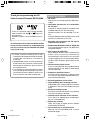 4
4
-
 5
5
-
 6
6
-
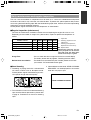 7
7
-
 8
8
-
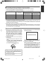 9
9
-
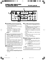 10
10
-
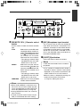 11
11
-
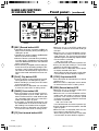 12
12
-
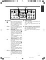 13
13
-
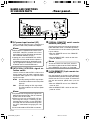 14
14
-
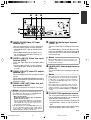 15
15
-
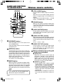 16
16
-
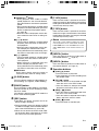 17
17
-
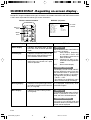 18
18
-
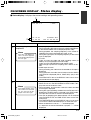 19
19
-
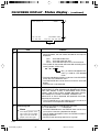 20
20
-
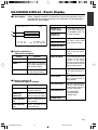 21
21
-
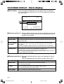 22
22
-
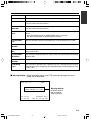 23
23
-
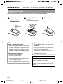 24
24
-
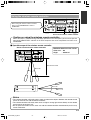 25
25
-
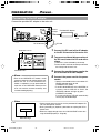 26
26
-
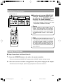 27
27
-
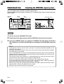 28
28
-
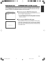 29
29
-
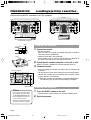 30
30
-
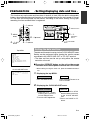 31
31
-
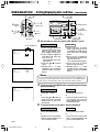 32
32
-
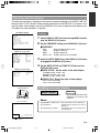 33
33
-
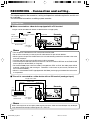 34
34
-
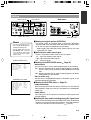 35
35
-
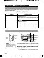 36
36
-
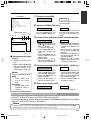 37
37
-
 38
38
-
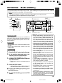 39
39
-
 40
40
-
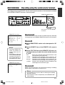 41
41
-
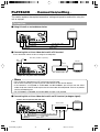 42
42
-
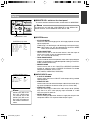 43
43
-
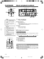 44
44
-
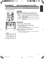 45
45
-
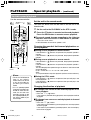 46
46
-
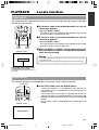 47
47
-
 48
48
-
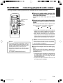 49
49
-
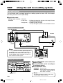 50
50
-
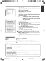 51
51
-
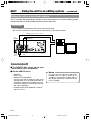 52
52
-
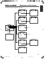 53
53
-
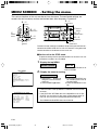 54
54
-
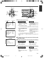 55
55
-
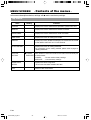 56
56
-
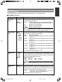 57
57
-
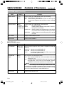 58
58
-
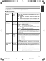 59
59
-
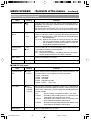 60
60
-
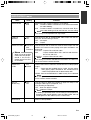 61
61
-
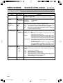 62
62
-
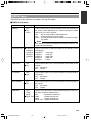 63
63
-
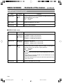 64
64
-
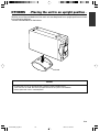 65
65
-
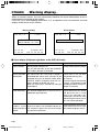 66
66
-
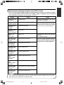 67
67
-
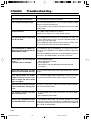 68
68
-
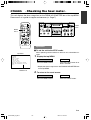 69
69
-
 70
70
-
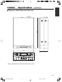 71
71
-
 72
72
-
 73
73
-
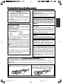 74
74
-
 75
75
-
 76
76
-
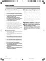 77
77
-
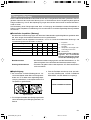 78
78
-
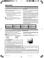 79
79
-
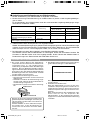 80
80
-
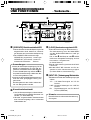 81
81
-
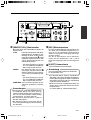 82
82
-
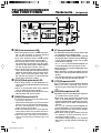 83
83
-
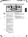 84
84
-
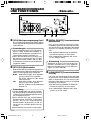 85
85
-
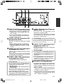 86
86
-
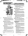 87
87
-
 88
88
-
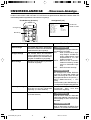 89
89
-
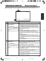 90
90
-
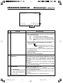 91
91
-
 92
92
-
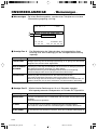 93
93
-
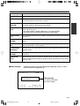 94
94
-
 95
95
-
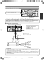 96
96
-
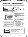 97
97
-
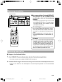 98
98
-
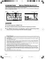 99
99
-
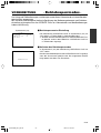 100
100
-
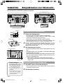 101
101
-
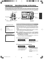 102
102
-
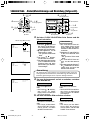 103
103
-
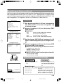 104
104
-
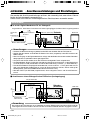 105
105
-
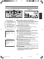 106
106
-
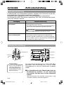 107
107
-
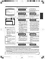 108
108
-
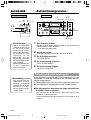 109
109
-
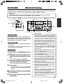 110
110
-
 111
111
-
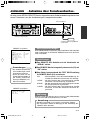 112
112
-
 113
113
-
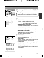 114
114
-
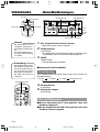 115
115
-
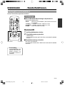 116
116
-
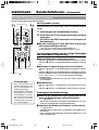 117
117
-
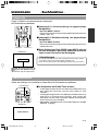 118
118
-
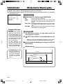 119
119
-
 120
120
-
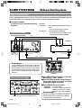 121
121
-
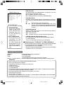 122
122
-
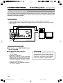 123
123
-
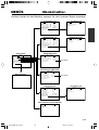 124
124
-
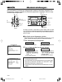 125
125
-
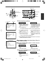 126
126
-
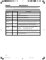 127
127
-
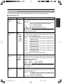 128
128
-
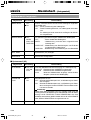 129
129
-
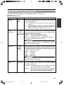 130
130
-
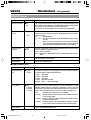 131
131
-
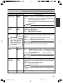 132
132
-
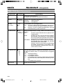 133
133
-
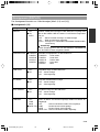 134
134
-
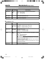 135
135
-
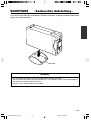 136
136
-
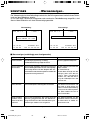 137
137
-
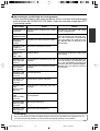 138
138
-
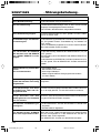 139
139
-
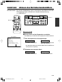 140
140
-
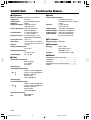 141
141
-
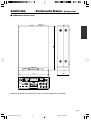 142
142
-
 143
143
-
 144
144
-
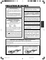 145
145
-
 146
146
-
 147
147
-
 148
148
-
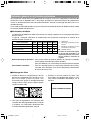 149
149
-
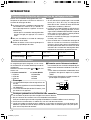 150
150
-
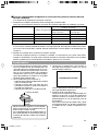 151
151
-
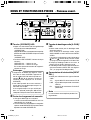 152
152
-
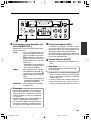 153
153
-
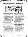 154
154
-
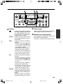 155
155
-
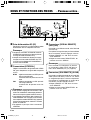 156
156
-
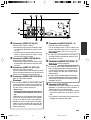 157
157
-
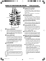 158
158
-
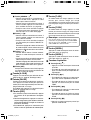 159
159
-
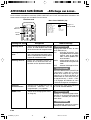 160
160
-
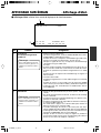 161
161
-
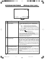 162
162
-
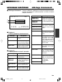 163
163
-
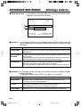 164
164
-
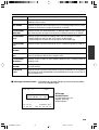 165
165
-
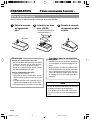 166
166
-
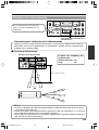 167
167
-
 168
168
-
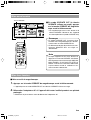 169
169
-
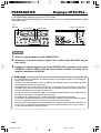 170
170
-
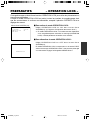 171
171
-
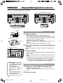 172
172
-
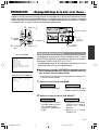 173
173
-
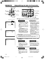 174
174
-
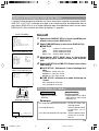 175
175
-
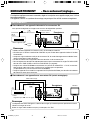 176
176
-
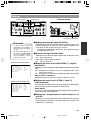 177
177
-
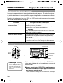 178
178
-
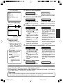 179
179
-
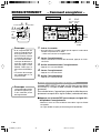 180
180
-
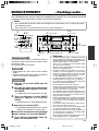 181
181
-
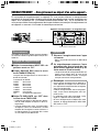 182
182
-
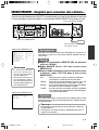 183
183
-
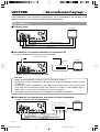 184
184
-
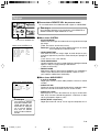 185
185
-
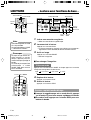 186
186
-
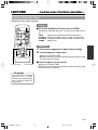 187
187
-
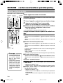 188
188
-
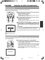 189
189
-
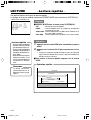 190
190
-
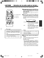 191
191
-
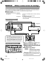 192
192
-
 193
193
-
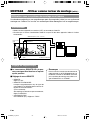 194
194
-
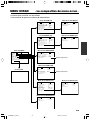 195
195
-
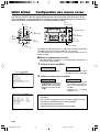 196
196
-
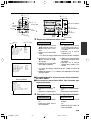 197
197
-
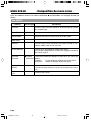 198
198
-
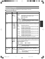 199
199
-
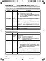 200
200
-
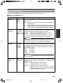 201
201
-
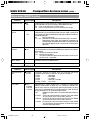 202
202
-
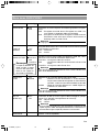 203
203
-
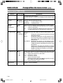 204
204
-
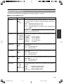 205
205
-
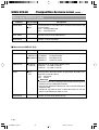 206
206
-
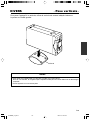 207
207
-
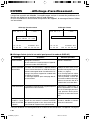 208
208
-
 209
209
-
 210
210
-
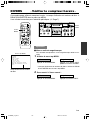 211
211
-
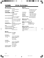 212
212
-
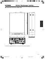 213
213
-
 214
214
-
 215
215
-
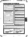 216
216
-
 217
217
-
 218
218
-
 219
219
-
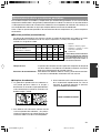 220
220
-
 221
221
-
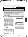 222
222
-
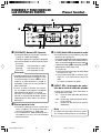 223
223
-
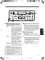 224
224
-
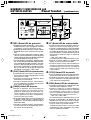 225
225
-
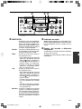 226
226
-
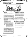 227
227
-
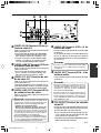 228
228
-
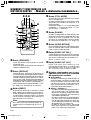 229
229
-
 230
230
-
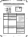 231
231
-
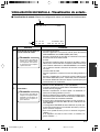 232
232
-
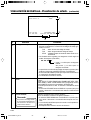 233
233
-
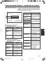 234
234
-
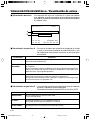 235
235
-
 236
236
-
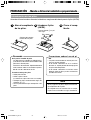 237
237
-
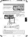 238
238
-
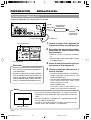 239
239
-
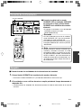 240
240
-
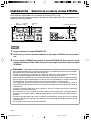 241
241
-
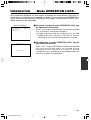 242
242
-
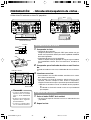 243
243
-
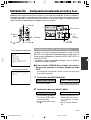 244
244
-
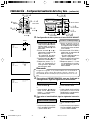 245
245
-
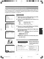 246
246
-
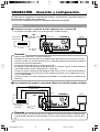 247
247
-
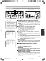 248
248
-
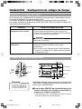 249
249
-
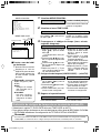 250
250
-
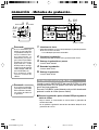 251
251
-
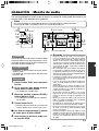 252
252
-
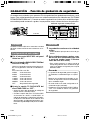 253
253
-
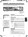 254
254
-
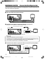 255
255
-
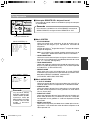 256
256
-
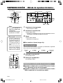 257
257
-
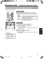 258
258
-
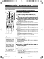 259
259
-
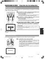 260
260
-
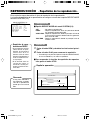 261
261
-
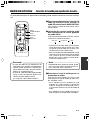 262
262
-
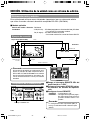 263
263
-
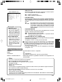 264
264
-
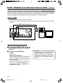 265
265
-
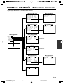 266
266
-
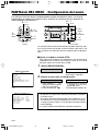 267
267
-
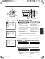 268
268
-
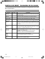 269
269
-
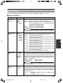 270
270
-
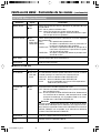 271
271
-
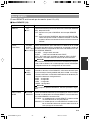 272
272
-
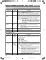 273
273
-
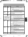 274
274
-
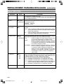 275
275
-
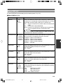 276
276
-
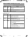 277
277
-
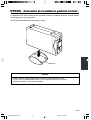 278
278
-
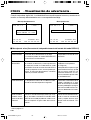 279
279
-
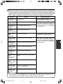 280
280
-
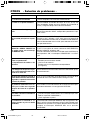 281
281
-
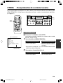 282
282
-
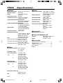 283
283
-
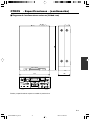 284
284
-
 285
285
-
 286
286
-
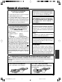 287
287
-
 288
288
-
 289
289
-
 290
290
-
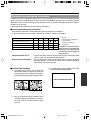 291
291
-
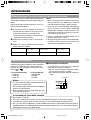 292
292
-
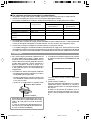 293
293
-
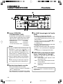 294
294
-
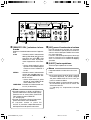 295
295
-
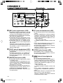 296
296
-
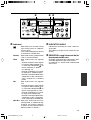 297
297
-
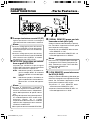 298
298
-
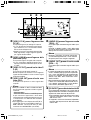 299
299
-
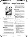 300
300
-
 301
301
-
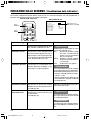 302
302
-
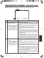 303
303
-
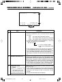 304
304
-
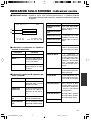 305
305
-
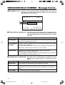 306
306
-
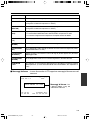 307
307
-
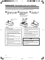 308
308
-
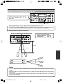 309
309
-
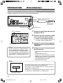 310
310
-
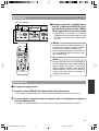 311
311
-
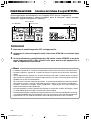 312
312
-
 313
313
-
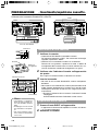 314
314
-
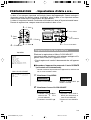 315
315
-
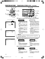 316
316
-
 317
317
-
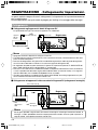 318
318
-
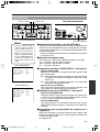 319
319
-
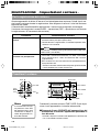 320
320
-
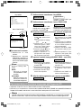 321
321
-
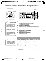 322
322
-
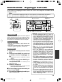 323
323
-
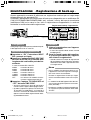 324
324
-
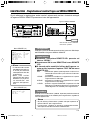 325
325
-
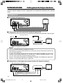 326
326
-
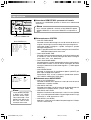 327
327
-
 328
328
-
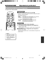 329
329
-
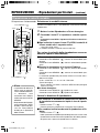 330
330
-
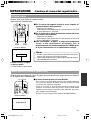 331
331
-
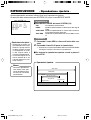 332
332
-
 333
333
-
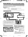 334
334
-
 335
335
-
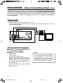 336
336
-
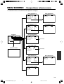 337
337
-
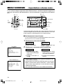 338
338
-
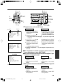 339
339
-
 340
340
-
 341
341
-
 342
342
-
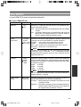 343
343
-
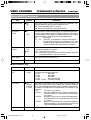 344
344
-
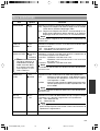 345
345
-
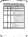 346
346
-
 347
347
-
 348
348
-
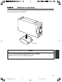 349
349
-
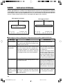 350
350
-
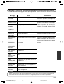 351
351
-
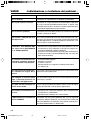 352
352
-
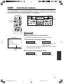 353
353
-
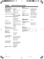 354
354
-
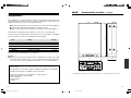 355
355
-
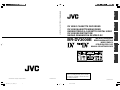 356
356


JVC VCR BR-DV600AE Manual de usuario
- Tipo
- Manual de usuario
- Este manual también es adecuado para
en otros idiomas
- français: JVC VCR BR-DV600AE Manuel utilisateur
- italiano: JVC VCR BR-DV600AE Manuale utente
- Deutsch: JVC VCR BR-DV600AE Benutzerhandbuch
Otros documentos
-
Sony AC-V615 Manual de usuario
-
-
-
-
-
Nikon DCR-PC10 Manual de usuario
-
-
Aiwa IC-M120 El manual del propietario
-
Aiwa IC-M84 El manual del propietario
-
Brigade MDR-304A-500 (3880) Manual de usuario