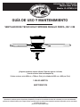
Hampton Bay 57289 Instrucciones de operación
- Categoría
- Ventiladores domésticos
- Tipo
- Instrucciones de operación
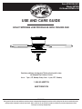
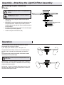
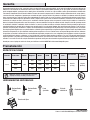
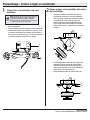
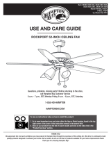
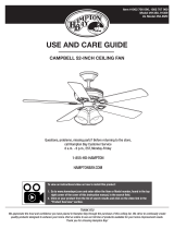
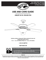
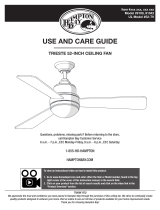
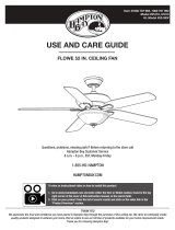
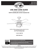
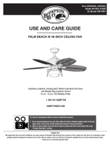
El Hampton Bay 57289 es un ventilador de techo de perfil bajo de 52 pulgadas con un potente motor que proporciona un flujo de aire abundante y silencioso, perfecto para refrescar habitaciones grandes. Incluye tres aspas reversibles en acabado arce y cerezo, para que elijas el que mejor se adapte a tu decoración, y una tulipa de cristal esmerilado que añade un toque elegante.
El Hampton Bay 57289 es un ventilador de techo de perfil bajo de 52 pulgadas con un potente motor que proporciona un flujo de aire abundante y silencioso, perfecto para refrescar habitaciones grandes. Incluye tres aspas reversibles en acabado arce y cerezo, para que elijas el que mejor se adapte a tu decoración, y una tulipa de cristal esmerilado que añade un toque elegante.


-
 1
1
-
 2
2
-
 3
3
-
 4
4
-
 5
5
-
 6
6
-
 7
7
-
 8
8
-
 9
9
-
 10
10
-
 11
11
-
 12
12
-
 13
13
-
 14
14
-
 15
15
-
 16
16
-
 17
17
-
 18
18
-
 19
19
-
 20
20
-
 21
21
-
 22
22
-
 23
23
-
 24
24


Hampton Bay 57289 Instrucciones de operación
- Categoría
- Ventiladores domésticos
- Tipo
- Instrucciones de operación
El Hampton Bay 57289 es un ventilador de techo de perfil bajo de 52 pulgadas con un potente motor que proporciona un flujo de aire abundante y silencioso, perfecto para refrescar habitaciones grandes. Incluye tres aspas reversibles en acabado arce y cerezo, para que elijas el que mejor se adapte a tu decoración, y una tulipa de cristal esmerilado que añade un toque elegante.
En otros idiomas
Documentos relacionados
-
 Hampton Bay 91854 Guía de instalación
-
 Hampton Bay 41359 Guía de instalación
-
 Hampton Bay 26612 Guía de instalación
-
Hampton Bay 52644 Guía de instalación
-
 Hampton Bay 68042 Guía de instalación
-
 Hampton Bay 99913 Instrucciones de operación
-
 Hampton Bay 51546 Guía de instalación
-
 Hampton Bay 91499 Guía de instalación
-
 Hampton Bay 51546 Guía de instalación
-
Hampton Bay 46010 Guía de instalación


