Lucent Technologies 4400 series Assembly Instructions Manual
- Tipo
- Assembly Instructions Manual

Icon-Labeled 4400-Series Telephones Assembly Instructions Page 1
MERLIN MAGIX is a trademark of Lucent Technologies Inc. in the US and other countries.
CIB 3195 CALA
Issue 1, June 2000
Icon-Labeled 4400-Series Telephones
Assembly Instructions
The icon-labeled 4400-Series telephones are digital single-line and multiline telephones designed
for use with Lucent Technologies’ MERLIN MAGIX™ Integrated System Release 1.0i. Most of the
instructions for the use of these telephones appear in the
4400 and 4400D Telephone User’s
Guide
and the
4406D+, 4412D+, 4424D+, and 4424LD+ Telephone User’s Guide
.
IMPORTANT SAFETY INSTRUCTIONS
The exclamation point in an equilateral triangle is intended to alert the user to
the presence of important operating and maintenance (servicing) instructions in
the literature accompanying the product.
To reduce the risk of fire, electrical shock, and injury to persons, follow these basic safety precautions
when installing telephone equipment:
■
Read and understand all instructions.
■
Placing equipment or other articles within two inches of the microphone, may decrease the
quality of performance of the speakerphone. For 4424LD+ and 4424D+ telephones, care should
be taken when connecting a DSS 4450 to ensure that placement of the DSS 4450 does not
interfere with the performance of the microphone on the right side of the telephone.
■
Follow all warnings and instructions marked on or packed with the product.
■
This product is intended to be installed and serviced by qualified service personnel only. Do not
disassemble this product. There are no user-serviceable parts inside.
■
Never push objects of any kind into this product through cabinet slots, as they may touch
dangerous voltage points or may short out parts, which could result in a risk of fire or electrical
shock.
■
Never install telephone wiring during a lightning storm.
■
Never touch uninsulated telephone wires or terminals unless the telephone wiring has been
disconnected at the network interface.
■
Never install a telephone jack in a wet location (for example a wet basement) unless the jack is
specifically designed for wet locations.
■
Do not install this product near water—for example, in a wet basement location.
■
Use caution when installing or modifying telephone lines.

Page 2 Icon-Labeled 4400-Series Telephones Assembly Instructions
CIB 3195 CALA
Issue 1, June 2000
■
Use only Lucent Technologies 1151A Power Supply Unit (PEC 2404-010) with the appropriate
input power cord PEC (24799). The Power Supply Unit is required for icon-labeled 4424LD+
telephones or with the icon-labeled 4424D+ when connecting a DSS 4450. The country-specific
input power cord is ordered by selecting the appropriate country attribute.
■
The 1151A Power Supply Unit is to be connected only to the type of main power source indicated
on the marking label. The main power source wall outlet must be installed near the equipment
and be readily accessible. Do not overload the wall outlet or use an extension cord.
■
The input power cord used with the 1151A Power Supply Unit is equipped with a grounding-type
plug appropriate for the country in which it is installed. This is a safety feature. If you are unable
to insert the plug into the outlet, contact an electrician to replace the obsolete outlet. Do not
defeat the safety purpose of the grounding plug.
■
Do not staple or otherwise secure the input power cord to the building surfaces. Do not allow
anything to rest on top of the cord. Do not locate the equipment where the cord will be abused by
persons walking on top of it.
■
Use only Lucent Technologies-recommended/approved 4400-Series telephone accessories.

Icon-Labeled 4400-Series Telephones Assembly Instructions Page 3
CIB 3195 CALA
Issue 1, June 2000
Line Cords
Line cords are shipped with all 4400-Series telephones and the DSS 4450. The line cord varies
according to the equipment:
■
Clear
14-foot, 6-position line cord with two conductors (D2R)—used to connect the 4400,
4400D, 4406D+, 4412D+, and 4424D+ telephones to the communications system wall jack. If
auxiliary power is needed, used to connect the 1151A Power Supply Unit to the
communications system wall jack.
■
Silver-Gray
14-foot, round line cord (M4BK)—used to connect the 1151A Power Supply Unit
to the 4424LD+ telephone or the 4424D+ telephone when connected to a DSS 4450. One end
of the M4BK cord has an 8-position plug and the other end has a 6-position plug.
■
3-foot, 8-position line cord with eight conductors (D8Y)—used to connect a DSS 4450 to a
4424LD+ or 4424D+ telephone or to another DSS 4450 via the jacks on the bottom of the DSS
4450 and the telephone.
1151A Power Supply Unit
An 1151A Power Supply Unit (PEC 2404-010) with the appropriate input power cord PEC (24799)
is
not
automatically shipped with the telephone and must be ordered separately. The 1151A
Power Supply Unit is required for icon-labeled 4424LD+ telephones or with the icon-labeled
4424D+ when connecting a DSS 4450. The country-specific input power cord is ordered by
selecting the appropriate country attribute.
See “Jacks and Placement of Cords” later in this document for instructions on installing the 1151A
Power Supply Unit for an icon-labeled 4424LD+ or with the icon-labeled 4424D+ when connected
to a DSS 4450.
CAUTION:
Do not use a different type of power supply from any other piece of equipment. Using another
power supply can severely damage the DSS 4450, the 4424LD+ telephone, or the 4424D+
telephone.

Page 4 Icon-Labeled 4400-Series Telephones Assembly Instructions
CIB 3195 CALA
Issue 1, June 2000
Microphone
The microphone on the 4406D+ is located on the bottom right front of the telephone. The
microphone on the 4412D+, 4424LD+, and 4424D+ telephones is located on the right side of each
telephone.
CAUTION:
Placing equipment or other articles within two inches of the microphone, may decrease the
quality of performance of the speakerphone. For 4424LD+ and 4424D+ telephones, care
should be taken when connecting a DSS 4450 to ensure that placement of the DSS 4450
does not interfere with the performance of the microphone on the right side of the telephone.
DSS 4450
One or two DSS 4450s can be connected to a 4424LD+ or 4424D+ telephone to enhance the call-
handling capabilities of a system operator with a Direct-Line Console (DLC) or a Queued Call
Console (QCC). When connected to a 4424LD+ telephone used as a system programming
console, the DSS 4450 facilitates system programming and centralized telephone programming
procedures. Most of the instructions for the use of the DSS 4450 by a system operator appear in
the
Direct-Line Console Operator’s Guide
and the
Queued Call Console Operator’s Guide
.
Instructions for use of the DSS 4450 during system programming or centralized telephone
programming appear in
System Programming
.
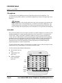
The DSS 4450 has three “pages” of 50 extensions or numbers. You can select the page you want
by pressing one of the page buttons on the bottom of the DSS 4450.
The DSS 4450 has the following characteristics:
■
50 line buttons with red
LEDs
■
3 page buttons with
green LEDs
■
6 buttons with green
LEDs reserved for
future use
DSS50
LEDs
(50)
Line
Buttons
(50)
Page
Buttons
Message
Status
Button
Reserved
Buttons

Icon-Labeled 4400-Series Telephones Assembly Instructions Page 5
CIB 3195 CALA
Issue 1, June 2000
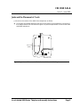
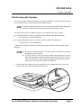
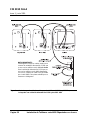
Jacks and the Placement of Cords
Jacks exist on the bottom of the 4400-Series telephones as follows:
■
On the 4400 and 4400D telephones the jacks on the bottom accommodate the connection of
the handset and the line cord. Refer to Figure 1 for jacks and placement of cords for the 4400
and 4400D telephones.
Figure 1. Jacks and Placement of Cords for the 4400 and 4400D Telephones
LINE
Line Cord
(D2R)
Handset Cord

Page 6 Icon-Labeled 4400-Series Telephones Assembly Instructions
CIB 3195 CALA
Issue 1, June 2000
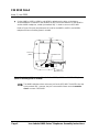
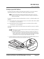
■
On the 4406D+, 4412D+, 4424D+, and 4424LD+ telephones the jacks on the bottom
accommodate the connection of the handset, the line cord, and a headset. For the 4424LD+
and the 4424D+ telephone, a wider jack marked “ADJ” is used to connect a DSS 4450.
Refer to Figure 2 for jacks and placement of cords for the 4406D+, 4412D+, and 4424D+
telephones when no auxiliary power is needed.
Figure 2. Jacks and Placement of Cords for the 4406D+, 4412D+ and 4424D+ Telephones
(when no auxiliary power is needed)
The 4406D+ telephone does not have a jack for the DSS 4450. The 4412D+ also has
a jack marked “ADJ”, however, the jack is reserved for future use and
cannot be
used
to connect a DSS 4450
LINE
Line Cord
(D2R)
Handset Cord
Headset Cord
ADJ

Icon-Labeled 4400-Series Telephones Assembly Instructions Page 7
CIB 3195 CALA
Issue 1, June 2000
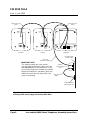
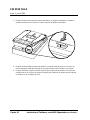
Follow these instructions and refer to Figure 3 to connect the 1151A Power Supply Unit to the
4424LD+ or to any 4400-Series telephone when auxiliary power is needed (for example, when
connecting one or two DSS 4450s to a 4424D+):
1. Turn the telephone and each DSS 4450 face down.
2. Connect the one end of the D8Y line cord (supplied with the DSS 4450) to the ADJ jack on the
telephone. Connect the other end of the D8Y line cord to the IN jack of the first DSS 4450 (next
to the telephone).
3. If you are connecting only one DSS 4450, go to Step 4.
If you are connecting a second DSS 4450, connect one end of the D8Y line cord (supplied with
the DSS 4450) to the OUT jack of the first DSS 4450 connected in Step 2. Connect the other
end of the D8Y line cord to the IN jack on the second DSS 4450 (farthest from the telephone).
4. Connect the 6-position plug at one end of the
silver-gray
M4BK line cord (ordered with the
1151A Power Supply Unit) to the LINE jack of the telephone. Connect the 8-position plug at
the other end of the silver-gray M4BK line cord to the PHONE jack of the 1151A Power Supply
Unit.
IMPORTANT NOTE:
This drawing in Figure 3 includes the cords used for connecting the 1219A Power Supply Unit
used with non-icon 4400-Series telephones. For 1151A Power Supply Unit used with icon-
labeled 4400-Series telephones substitute a silver-gray M4BK line cord for the satin-silver
D4BU cord shown in the drawing.
5. Connect one end of the
clear
D2R line cord (packaged with the 4400-Series telephones and
the DSS 4450) to the LINE jack of the 1151A Power Supply Unit. Connect the other end of the
clear D2R line cord to communications system wall jack.
6. Connect the 1151A Power Supply Unit into a wall outlet.
7. Turn the telephone and the DSS 4450s face up.
■
If the telephone will be wall mounted using the optional wall-mounting stand, you
must run the headset and handset cords out the channel on the side of the
telephone.
■
The 4424LD+ telephone and the DSS 4450 cannot be wall mounted.
■
If the telephone does not work properly after all cords are connected, check to be
sure that the silver-gray M4BK line cord and the clear D2R line cords are
connected properly as shown in Figure 3.

Page 8 Icon-Labeled 4400-Series Telephones Assembly Instructions
CIB 3195 CALA
Issue 1, June 2000
Figure 3. Jacks and Placement of Cords for the 4424LD+ and 4424D+ Telephones
Including 1151A Power Supply Unit and two DSS 4450s
LINE
TEL
OUT IN OUT IN
LINE ADJ
Auxiliary
Power Supply
Unit
Communications
System Wall Jack
Grounding Type
Power Outlet
Telephone1st DSS2nd DSS
DSS 4450 Cord
(D8Y)
DSS 4450 Cor
d
(D8Y)
Line Cord
(D2R)
Line Cord
(Satin Silver D4BU)
IMPORTANT NOTE:
This drawing includes the cords used for
connecting the 1219A Power Supply Unit used
with
non-icon
4400-Series telephones. For the
1151A Power Supply Unit, used with icon-labeled
4400-Series telephones, substitute a silver-gray
M4BK line cord for the satin-silver D4BU cord
shown in the drawing.

Icon-Labeled 4400-Series Telephones Assembly Instructions Page 9
CIB 3195 CALA
Issue 1, June 2000
Wall-Mounting the Telephone
You can mount all the 4400-Series telephones except the 4424LD+ on a wall by using the optional
color-contrasted stand. The DSS 4450 cannot be wall mounted.
The wall-mounting stand is available in gray only. The ordering codes are as follows:
■
Small Wall-Mounting Stand for use with the 4400, 4400D, and 4406D+ telephones:
— PEC 4499-SML, comcode 108541210
■
Large Wall-Mounting Stand for use with the 4412D+ and 4424D+ telephones:
— PEC 4499-LRG, comcode 108541293
To wall mount a 4400-Series telephone, follow these steps to attach a stand to a 4400-Series
telephone:
1. Place the tab on the thicker end of the stand (this is the moveable tab) into the slot at the
bottom of the back side of the 4400-Series telephone
The optional wall-mounting stand can also be used with all 4400-Series telephones
and the DSS 4450 to increase the viewing angle when used on a desk.
■
Before you assemble the stand, you must have all cords attached and running
through their proper channels.
■
To use the stand to increase the angle of a 4400-Series telephone on a desk
follow the steps below but turn the stand around so that the thinner end of the
stand is at the bottom of the back side of the 4400-Series telephone and the
thicker end is at the top of the 4400-Series telephone.
LINE ADJ

Page 10 Icon-Labeled 4400-Series Telephones Assembly Instructions
CIB 3195 CALA
Issue 1, June 2000
2. Push up on the stand toward the top of the telephone, and place the tab on the thinner end of
the stand into the slot at the top of the 4400-Series telephone.
3. After you have attached the stand to the telephone, plug the line cord into the wall jack and
store the extra line cord in the open pocket space between the telephone and the stand.
4. Place the telephone against the wall so that the screwheads on the mounting plate enter the
holes in the stand. Then pull the telephone down so that the screwheads slide into the cutout
channels.
LINE
ADJ

Instalación de Teléfonos serie 4400 Etiquetados con Iconos Pagina 11
CIB 3195 CALA
Issue 1, Junio 2000
Instalación de Teléfonos serie 4400
Etiquetados con Iconos
Descripción General
Los teléfonos serie 4400 etiquetados con iconos son teléfonos digitales de una sola línea y de
líneas múltiples diseñados para usarse con el Sistema integrado MERLIN MAGIX™ versión 1.0i
de Lucent Technologies. La mayoría de las instrucciones para estos teléfonos aparecen en la
Guía
del usuario de los teléfonos 4400 y 4400D
y la
Guía del usuario de los teléfonos 4406D+, 4412D+,
4424D+ y 4424LD+
.
INSTRUCCIONES IMPORTANTES DE SEGURIDAD
El signo de admiración dentro de un triángulo equilátero en la literatura que
acompaña al producto, tiene la intención de alertar al usuario sobre la presencia
de instrucciones importantes referentes a la operación y al mantenimiento
(servicio).
Para reducir el riesgo de incendio, choque eléctrico y lesiones a personas, siga estas precauciones
básicas de seguridad al instalar el equipo telefónico:
■
Lea y entienda todas las instrucciones.
■
La colocación del equipo u otros artículos a dos pulgadas del micrófono puede reducir la calidad
de rendimiento del teléfono con micrófono y altavoz. Para los teléfonos 4424LD+ y 4424D+, debe
tenerse cuidado al conectar un DSS 4450 para garantizar que la colocación del DSS 4450 no
interfiera con el rendimiento del micrófono en el lado derecho del teléfono.
■
Siga todas las advertencias e instrucciones marcadas en el producto o incluidas con éste.
■
Este producto está destinado para que su instalación y mantenimiento sean realizados
únicamente por personal calificado de servicio. No desarme este producto. No contiene partes
internas que el usuario pueda reparar.
■
Nunca inserte objetos de ninguna clase dentro de este producto a través de las ranuras del
gabinete, ya que éstos pueden tocar puntos de voltaje peligrosos o provocar corto en las partes,
lo cual puede producir incendios o choques eléctricos.
■
Nunca instale cableado telefónico durante una tormenta eléctrica.
■
Nunca toque los hilos telefónicos ni las terminales que no cuentan con aislamiento, a menos que
el cableado telefónico se haya desconectado en la interface de la red.
■
Nunca instale un contacto telefónico en un lugar húmedo (por ejemplo, un sótano húmedo), a
menos que el contacto esté diseñado específicamente para lugares húmedos.
■
No instale este producto cerca de agua, como por ejemplo, en un sótano húmedo.
■
Tenga precaución al instalar o modificar las líneas telefónicas.

Pagina 12 Instalación de Teléfonos serie 4400 Etiquetados con Iconos
CIB 3195 CALA
Issue 1, Junio 2000
■
Use sólo la unidad de alimentación de energía 1151A de Lucent Technologies (PEC 2404-010)
con el PEC del cable de energía de entrada correcto (24799). La unidad de la fuente de
alimentación de energía se requiere para teléfonos 4424LD+ etiquetados con iconos o con el
4424D+ etiquetados con iconos, al conectar un DSS 4450. El cable de energía de entrada
específico para el país se solicita seleccionando el atributo correcto del país.
■
La unidad de fuente de alimentación de energía 1151A se conectará solamente al tipo de fuente
de alimentación principal que se indica en la etiqueta de marca. La salida de pared de la fuente de
alimentación principal debe instalarse cerca del equipo y ser de fácil acceso. No sobrecargue la
salida de pared ni use un cable de extensión.
■
El cable de energía de entrada usado con la unidad de fuente de alimentación 1151A está
equipada con un enchufe tipo aterrizaje adecuado para el país en que está instalado. Esta es una
función de seguridad. Si no puede insertar el enchufe en la salida, consiga a un electricista para
que reemplace la salida obsoleta. No trate de alterar el enchufe de conexión a tierra.
■
No engrape ni fije en otra forma el cable de energía de entrada a las superficies de los edificios.
No permita que ningún objeto descanse sobre el cable de energía. No coloque este equipo donde
el cable pueda ser maltratado por personas que caminen sobre él.
■
Use solamente accesorios para teléfonos serie 4400 recomendados o aprobados por Lucent
Technologies.
Cables de Línea
0
Los cables de línea se incluyen con todos los teléfonos serie 4400 y el DSS 4450. El cable de
línea varía de acuerdo con el equipo:
■
Transparente
cable de energía de 6 posiciones y 14 pies con dos conductores (D2R), usados
para conectar los teléfonos 4400, 4400D, 4406D+ y 4424D+ al contacto de pared del sistema
de comunicaciones. Si necesita energía auxiliar, se usa para conectar la unidad de fuente de
alimentación 1151A al contacto de pared del sistema de comunicaciones.
■
Gris plata
cable de línea redondo de 14 pies (M4BK), que se usa para conectar la unidad de
la fuente de alimentación al teléfono 4424LD+ o el teléfono 4424D+ al conectarse a un DSS
4450. Un extremo del cable M4BK tiene un contacto de 8 posiciones y el otro extremo tiene un
contacto de 6 posiciones.
■
Cable de línea de 8 posiciones y de 3 pies, con ocho conductores (D8Y), que se usa para
conectar un DSS 4450 a un teléfono 4424LD+ o 4424D+ o a otro DSS 4450 mediante los
contactos en la parte inferior del DSS 4450 y el teléfono.

Instalación de Teléfonos serie 4400 Etiquetados con Iconos Pagina 13
CIB 3195 CALA
Issue 1, Junio 2000
Unidad de Alimentación de Energía 1151A
0
Una unidad de fuente de alimentación 1151A (PEC 2404-010) con el PEC de cable de energía de
entrada correcto (24799)
no
se incluye automáticamente con el teléfono y debe pedirse por
separado. La unidad de la fuente de alimentación 1151A se requiere para teléfonos 4424LD+
etiquetados con iconos o con el 4424D+ etiquetados con iconos, al conectar un DSS 4450. El
cable de alimentación de entrada específico para el país se solicita seleccionando el atributo
correcto del país.
Véase “Contactos y colocación de cables” más adelante en este documento para obtener
instrucciones sobre la instalación de la unidad de alimentación 1151A para un 4424LD+
etiquetado con iconos o con el 4424D+ etiquetado con iconos al conectarse a un DSS 4450.
CAUTION:
No use un tipo diferente de fuente de alimentación de algún otro componente del
equipo. El uso de otra fuente de alimentación puede dañar gravemente el DSS 4450, el
teléfono 4424LD+ o el teléfono 4424D+.
Micrófono
0
El micrófono en el 4406D+ se localiza en la parte inferior delantera del lado izquierdo del teléfono.
El micrófono en los teléfonos 4421D+, 4424LD+ y 4424D+ se encuentra en la lado derecho de
cada teléfono.
CAUTION:
La colocación del equipo u otros artículos a dos pulgadas del micrófono puede
reducir la calidad de rendimiento del teléfono con micrófono y altavoz. Para los
teléfonos 4424LD+ y 4424D+, debe tenerse cuidado al conectar un DSS 4450 para
garantizar que la colocación del DSS 4450 no interfiera con el rendimiento del
micrófono en el lado derecho del teléfono.

Pagina 14 Instalación de Teléfonos serie 4400 Etiquetados con Iconos
CIB 3195 CALA
Issue 1, Junio 2000
DSS 4450
0
Es posible conectar uno o dos DSS 4450 a un teléfono 4424DL+ o 4424D+ para mejorar las
capacidades de manejo de llamadas de un operador del sistema con un Consola de Línea Directa
(DLC) o una Consola de Llamadas en Cola de Espera (QCC). Cuando está conectado a un
teléfono 4424LD+ usado como una consola de programación del sistema, el DSS 4450 facilita los
procedimientos de programación del sistema y de programación centralizada del teléfono. La
mayoría de las instrucciones para el uso del DSS 4450 por parte de un operador del sistema,
aparecen en la
Guía del operador de la Consola de Línea Directa
y la
Guía del operador de la
Consola de Llamadas en Cola de Espera
. Las instrucciones para el uso del DSS 4450 durante la
programación del sistema o la programación centralizada del teléfono aparecen en la
Programación del sistema
.
El DSS 4450 tiene tres “páginas” de 50 extensiones o números. Puede seleccionar la página que
desee marcando uno de los botones de página en la parte inferior del DSS 4450.
El DSS 4450 cuenta con las siguientes características:
■
Cincuenta botones de
línea con LED rojos
■
Tres botones de página
con LED verdes
■
Seis botones con LED
verdes reservados para
uso futuro

Instalación de Teléfonos serie 4400 Etiquetados con Iconos Pagina 15
CIB 3195 CALA
Issue 1, Junio 2000
Contactos y la Colocación de Cables
0
Los contactos se encuentran en la parte inferior de los teléfonos serie 4400, de la siguiente forma:
■
En los teléfonos 4400 y 4400D, los contactos en la parte inferior aceptan la conexión del
auricular y el cable de energía. Consulte la figura 4 para los contactos y la colocación de
cables para los teléfonos 4400 y 4400D.
Figura 4. Contactos y Colocación de Cables para los Teléfonos 4400 y 4400D

Pagina 16 Instalación de Teléfonos serie 4400 Etiquetados con Iconos
CIB 3195 CALA
Issue 1, Junio 2000
■
En los teléfonos 4406D+, 4412D+, 4424D+ y 4424LD+, los contactos en la parte inferior
aceptan la conexión del auricular, el cable de línea y una diadema. Para el teléfono 4424LD+ y
4424D+, se usa un contacto más amplio marcado como “ADJ” para conectar un DSS 4450.
Consulte la figura 5 para los contactos y la colocación de cables para los teléfonos 4406D+,
4412D+ y 4424D+ al no necesitar energía auxiliar.
Figura 5. Contactos y Colocación de Cables para los Teléfonos 4406D+, 4412D+ y 4424D+
(cuando no se necesite energía auxiliar).
El teléfono 4406D+ no tiene un contacto para el DSS 4450. El 4412D+ también tiene
un contacto marcado “ADJ”, sin embargo, el contacto se reserva para uso futuro y
no puede usarse
para conectar un DSS 4450.

Instalación de Teléfonos serie 4400 Etiquetados con Iconos Pagina 17
CIB 3195 CALA
Issue 1, Junio 2000
Siga estas instrucciones y consulte la figura 6 para conectar la unidad de fuente de alimentación
1151A al teléfono 4424DL+ p a cualquier teléfono serie 4400 cuando se necesite energía auxiliar
(por ejemplo, al conectar uno o dos DSS 4450 a un 4424D+).
1.Voltee hacia abajo el teléfono y cada DS 4450.
2.Conecte un extremo del cable de energía D8Y (que se incluye con el DSS 4450) al contacto
ADJ en el teléfono. Conecte el otro extremo del cable de energía D8Y al contacto IN del
primer DSS 4450 (a un lado del teléfono).
3.Si sólo está conectando un DSS 4450, continúe con el paso 4.
Si está conectando un segundo DSS 4450, conecte un extremo del cable de línea D8Y (que
se incluye con el DSS 4450) al contacto OUT del primer DSS 4450 conectado en el paso 2.
Conecte el otro extremo del cable de energía D8Y al contacto IN en el segundo DSS 4450
(más alejado del teléfono).
4.Conecte el enchufe de seis posiciones en un extremo del cable de línea M4BK
gris plata
(que
se pide con la unidad de alimentación 1151A) al contacto LINE del teléfono. Conecte el
contacto de ocho posiciones en el otro extremo del cable de energía M4BK color gris plata, al
contacto PHONE de la unidad de alimentación 1151A.
NOTA IMPORTANTE:
Este diagrama de la figura 6 incluye los cables usados para conectar la unidad de
alimentación 1219A que se usa con los teléfonos serie 4400 sin icono. Para la unidad de
alimentación 1151A que se usa con los teléfonos serie 4400 etiquetados con iconos, sustituya
un cable color gris M4BK por el cable D4BU color plata satinado que se muestra en el
diagrama.
5.Conecte un extremo del cable de línea D2R
transparente
(que se incluye con los teléfonos
serie 4400 y el DSS 4450) al contacto LINE de la unidad de alimentación 1151A. Conecte el
otros extremo del cable de línea D2R transparente al contacto de pared del sistema de
comunicaciones.
6.Conecte la unidad de alimentación 1151A a una salida de pared.
7.Voltee hacia arriba el teléfono y cada DS 4450.
■
Si el teléfono se montará usando el soporte opcional para montaje en pared, debe
tender los cables del auricular y la diadema en el canal lateral del teléfono.
■
El teléfono 4424LD+ y el DSS 4450 no pueden montarse en la pared.
■
Si el teléfono no funciona correctamente después de conectar todos los cables,
verifique para asegurarse que el cable de línea M4Bk color gris plata y los cables
de línea D2R transparentes estén conectados correctamente como se muestra en
la figura 6.

Pagina 18 Instalación de Teléfonos serie 4400 Etiquetados con Iconos
CIB 3195 CALA
Issue 1, Junio 2000
Figura 6. Contactos y colocación de cables para los teléfonos 4424LD+ y 4424LD+,
incluyendo una unidad de alimentación 1151A y dos DSS 4450
NOTA IMPORTANTE:
Este diagrama incluye los cables usados para
conectar la unidad de alimentación 1219A que
se usa con los teléfonos serie 4400
sin icono
.
Para la unidad de alimentación 1151A que se
usa con los teléfonos serie 4400 etiquetados
con iconos, sustituya un cable color gris M4BK
por el cable D4BU color plata satinado que se
muestra en el diagrama.

Instalación de Teléfonos serie 4400 Etiquetados con Iconos Pagina 19
CIB 3195 CALA
Issue 1, Junio 2000
Montaje en pared del Teléfono
0
No puede montar todos los teléfonos serie 4400 excepto el 4424LD+ en una pared, usando el
soporte opcional de color en contraste. El DSS 4450 no puede montarse en pared.
El soporte para montaje en pared sólo está disponible en color gris. Los códigos de pedido son los
siguientes:
■
Soporte pequeño para montaje en pared para usarse con los teléfonos 4400, 4400D y 4406D+:
— PEC 4499-SML, comcode 108541210
■
Soporte grande para montaje en pared para usarse con los teléfonos 4412D+ y 4424D+:
— PEC 4499-LRG, comcode 108541293
Para montar en pared un teléfono serie 4400, siga estos pasos para fijar un soporte a un teléfono
serie 4400:
1. Coloque la lengüeta en el extremo ancho del soporte (esta es la lengüeta movible) esté en la
ranura en la parte inferior del lado posterior del teléfono serie 4400.
El soporte opcional para montaje en pared también puede usarse con todos los
teléfonos serie 4400 y el DSS 4450 para incrementar el ángulo de visualización al
usarse en un escritorio.
■
Antes de armar el soporte, debe tener todos los cables conectados y tendidos en
sus canaletas correctas.
■
Para usar el soporte para incrementar el ángulo de un teléfono serie 4400 en un
escritorio, siga los pasos a continuación pero voltee el soporte de manera que el
extremo angosto esté en la parte inferior del lado posterior del teléfono serie 4400
y el extremo ancho esté en la parte superior del teléfono serie 4400.
L
IN
E
A
D
J

Pagina 20 Instalación de Teléfonos serie 4400 Etiquetados con Iconos
CIB 3195 CALA
Issue 1, Junio 2000
2. Empuje el soporte hacia la parte superior del teléfono y coloque la lengüeta en el extremo
angosto del soporte en la ranura en la parte superior del teléfono serie 4400.
3. Después de haber fijado el soporte al teléfono, conecte el cable de línea en el contacto de
pared y guarde el cable de línea extra en el espacio abierto entre el teléfono y el soporte.
4. Coloque el teléfono contra la pared de manera que la cabeza de los tornillos en la placa de
montaje entre en los orificios del soporte. Después jale el teléfono de manera que las cabezas
se deslicen en las canaletas de corte.
LINE
ADJ
-
 1
1
-
 2
2
-
 3
3
-
 4
4
-
 5
5
-
 6
6
-
 7
7
-
 8
8
-
 9
9
-
 10
10
-
 11
11
-
 12
12
-
 13
13
-
 14
14
-
 15
15
-
 16
16
-
 17
17
-
 18
18
-
 19
19
-
 20
20


Lucent Technologies 4400 series Assembly Instructions Manual
- Tipo
- Assembly Instructions Manual
en otros idiomas
- English: Lucent Technologies 4400 series
Artículos relacionados
Otros documentos
-
Avaya 4606/4612/4624 IP Telephones Manual de usuario
-
-
-
-
Epson Stylus Photo 2100 El manual del propietario
-
-
SICK VS/VE18-2 Instrucciones de operación
-
 GOODMAN PGB120245-5 Manual de usuario
