Faber CRIS30SS300 Guía de instalación
- Categoría
- Campanas de cocina
- Tipo
- Guía de instalación

CRIS36SS300 CRIS36SS400 CRIS36SS600
CRIS30SS300 CRIS30SS400 CRIS30SS600
Installation Instructions
Use and Care Information
Instructions d'installation
Utilisez et d'entretien
Instrucciones de instalación
Información de uso y cuidado
NEW CRISTAL
Version 06/14 - Page 1
READ THESE INSTRUCTIONS BEFORE YOU START INSTALLING THIS RANGEHOOD
WARNING: - TO REDUCE THE RISK OF A RANGE TOP GREASE FIRE: a) Never leave surface units unattended at high
settings. Boilovers cause smoking and greasy spillovers that may ignite. Heat oils slowly on low or medium setting. b) Always turn
hood ON when cooking at high heat or when flambeing food (i.e. Crepes Suzette, Cherries Jubilee, Pepper-corn Beef Flambé). c)
Clean ventilating fans frequently. Grease should not be allowed to accumulate on fan or filter. d) Use proper pan size. Always use
cookware appropriate for the size of the surface element.
WARNING:aBased on “Kitchen Firesafety Tips” published by NFPA. - TO REDUCE THE RISK OF INJURY TO PERSONS
IN THE EVENT OF A RANGE TOP GREASE FIRE, OBSERVE THE FOLLOWING: SMOTHER FLAMES with a close-fitting
lid, cookie sheet, or metal tray, then turn off the burner. BE CAREFUL TO PREVENT BURNS. If the flames do not go
out immediately EVACUATE AND CALL THE FIRE DEPARTMENT. NEVER PICK UP A FLAMING PAN - You may be
burned. DO NOT USE WATER, including wet dishcloths or towels - a violent steam explosion will result. Use an
extinguisher ONLY if:
1. You know you have a Class ABC extinguisher, and you already know how to operate it. 2. The fire is
small and contained in the area where it started. 3. The fire department is being called. 4. You can fight the fire with your back to
an exit.
ALL WALL AND FLOOR OPENINGS WHERE THE RANGEHOOD IS INSTALLED MUST BE SEALED.
This rangehood requires at least 24" of clearance between the bottom of the rangehood and the cooking surface or countertop.
This minimum clearance may be higher depending on local building code. For example, for gas ranges, a minimum of 30"
may be required. Overhead cabinets on both sides of this unit must be a minimum of 24" above the cooking surface or
countertop. Consult the cooktop or range installation instructions given by the manufacturer before making any cutouts.
MOBILE HOME INSTALLATION The installation of this rangehood must conform to the Manufactured Home Construction and
Safety Standards, Title 24 CFR, Part 3280 (formerly Federal Standard for Mobile Home Construction and Safety, Title 24, HUD,
Part 280). Four wire power supply must be used and the appliance wiring must be revised. See Electrical Requirements.
LISEZ BIEN CETTE FICHE AVANT D'INSTALLER LA HOTTE
AVERTISSEMENT - POUR MINIMISER LE RISQUE D’UN FEU DE GRAISSE SUR LA TABLE DE CUISSON : a) Ne jamais
laisser un élément de la table de cuisson fonctionner sans surveillance à la puissance de chauffage maximale; un renversement/
débordement de matière graisseuse pourrait provoquer une inflammation et le génération de fumée. Utiliser toujours une puissance
de chauffage moyenne ou basse pour le chauffage d’huile. b) Veiller à toujours faire fonctionner le ventilateur de la hotte lors d’une
cuisson avec une puissance de chauffage élevée ou lors de la cuisson d’un mets à flamber (i.e. Crepes Suzette, Cherries Jubilee,
Peppercorn Beef Flambé). c) Nettoyer fréquemment les ventilateurs d’extraction. Veiller à ne pas laisser de la graisse s’accumuler
sur les surfaces du ventilateur ou des filtres. d) Utiliser toujours un ustensile de taille appropriée. Utiliser toujours un ustensile de
taille adapté à la taille de l’élément chauffant.
AVERTISSEMENT:Basé sur "Kitchen Firesafety Tips" publié par NFPA. - POUR PRÉVENIR LES BLESSURES EN CAS
DE FEU SUIVRE LES RECOMMANDATIONS SUIVANTES: ÉTOUFFEZ LE FEU avec un couvercle métallique et fermez le
brûleur. Si le feu ne s'éteint pas tout de suite, QUITTEZ LES LIEUX ET APPELEZ LES POMPIERS. NE TOUCHEZ
JAMAIS UNE CASSEROLE EN FLAMMES. N'UTILISEZ JAMAIS DE L'EAU ou un torchon mouillé pour éteindre le feu -
ce qui pourrait causer une explosion de vapeur. N'utilisez un extincteur que si: 1. Vous avez un modèle ABC et vous
connaissez bien son mode d'emploi. 2. Le feu est petit et peu répandu. 3. Les pompiers sont déjà prévenus. 4. Vous avez une
sortie derrière vous.
TOUTE OUVERTURE DANS LE MUR OU LE PLANCHER À PROXIMITÉ DE LA HOTTE DOIT ÊTRE SCELLÉ
Gardez 24 po. de hauteur entre le bas de la hotte et la surface de cuisson. Cette hauteur minimum peut être plus haute suivant le
code municipal. Par exemple, les cuisinières à gaz peuvent requérir 30 po. de hauteur. Les armoires au-dessus de chaque
côté devront être au moins à 24 po. au-dessus de la surface de cuisson. Consultez la fiche technique avant de découper les
armoires. L'installation de cette hotte doit être conforme aux Réglements de Manufactured Home Construction and Safety
Standards, titre 24 CFR, Section 3280 (anciennement Federal Standard for Mobile Home Construction and Safety Standards,
titre 24 CFR, Section 3280 (anciennement Federal Standard for Mobile Home Construction and Safety, titre 24, HUD, Section
280). Le branchement électrique se fait avec une raccordement à 4 fils. Consultez la fiche technique électrique.
CRISTAL HC SS - Halogen
Stainless Slideout Rangehood
• Installation Instructions
• Use and Care Information
READ AND SAVE THESE INSTRUCTIONS
The Installer must leave these instructions with the homeowner.
The homeowner must keep these instructions for future reference
and for local electrical inspectors' use.
CAUTION:- To reduce risk of fire and to properly exhaust air, be sure to duct air outside – Do not vent exhaust air into spaces
within walls or ceilings or into attics, crawl spaces, or garages.
PRUDENCE:- - Afin de réduire les risques d'incendie assurez-vous que l'air soit correctement évacué à l'extérieur. L'air ne doit pas être
évacué dans les espaces libres entre les parois ou faux plafonds, auvents, garages.

2
READ AND SAVE THESE INSTRUCTIONS BEFORE YOU START
INSTALLING THIS RANGEHOOD
WARNING: - TO REDUCE THE RISK OF A RANGE TOP GREASE FIRE:
a) Never leave surface units unattended at high settings. Boilovers cause smoking and
greasy spillovers that may ignite. Heat oils slowly on low or medium setting.
b)AlwaysturnhoodONwhencookingathighheatorwhenambeingfood(i.e.Crepes
Suzette, Cherries Jubilee, Peppercorn Beef Flambé).
c) Clean ventilating fans frequently. Grease should not be allowed to accumulate on fan
orlter.
d) Use proper pan size. Always use cookware appropriate for the size of the surface element.
WARNING: - TO REDUCE THE RISK OF INJURY TO PERSONS IN THE EVENT OF A
RANGE TOP GREASE FIRE, OBSERVE THE FOLLOWING*:
a)SMOTHERFLAMESwithaclose-ttinglid,cookiesheet,ormetaltray,thenturnofftheburner.
BECAREFULTOPREVENTBURNS.IftheamesdonotgooutimmediatelyEVACUATE
AND CALL THE FIRE DEPARTMENT.
b) NEVER PICK UP A FLAMING PAN - You may be burned.
c) DO NOT USE WATER, including wet dishcloths or towels - a violent steam explosion will
result.
d) Use an extinguisher ONLY if:
1. You know you have a Class ABC extinguisher, and you already know how to operate it.
2. Thereissmallandcontainedintheareawhereitstarted.
3. Theredepartmentisbeingcalled.
4. Youcanghttherewithyourbacktoanexit.
* Based on "Kitchen Firesafety Tips" published by NFPA
WARNING - TO REDUCE THE RISK OF FIRE OR ELECTRIC SHOCK, do not use this
fan with any solid-state speed control device.
WARNING - TO REDUCE THE RISK OF FIRE, ELECTRICAL SHOCK, OR INJURY TO
PERSONS, OBSERVE THE FOLLOWING:
1. Use this unit only in the manner intended by the manufacturer. If you have any
questions, contact the manufacturer.
2. Before servicing or cleaning unit, switch power off at service panel and lock the
service disconnecting means to prevent power from being switched on acciden-
tally. When the service disconnecting means cannot be locked, securely fasten a
prominent warning device, such as a tag, to the service panel.
CAUTION: For General Ventilating Use Only. Do Not Use To Exhaust Hazardous or
Explosive Materials and Vapors.
WARNING - TO REDUCE THE RISK OF FIRE, ELECTRICAL SHOCK, OR INJURY TO
PERSONS, OBSERVE THE FOLLOWING:
1. InstallationWorkAndElectricalWiringMustBeDoneByQualiedPerson(s)InAccor-
dance With All Applicable Codes And Standards, Including Fire-Rated Construction.
2. Sufcientairisneededforpropercombustionandexhaustingofgasesthrough
theue(chimney)offuelburningequipmenttopreventbackdrafting.Followthe
heating equipment manufacturer's guideline and safety standards such as those
publishedbythe National FireProtectionAssociation (NFPA),and the American
SocietyforHeating,RefrigerationandAirConditioningEngineers(ASHRAE),and
the local code authorities.
3. When cutting or drilling into wall or ceiling, do not damage electrical wiring and
other hidden utilities.
4. Ducted fans must always be vented to the outdoors.

3
ALL WALL AND FLOOR OPENINGS WHERE THE RANGEHOOD IS INSTALLED MUST
BE SEALED.
This rangehood requires at least 24" of clearance between the bottom of the rangehood
and the cooking surface or countertop. This hood has been approved by UL at this distance
from the cooktop.
This minimum clearance may be higher depending on local building codes. For gas cooktops
and combination ranges, a minimum of 30" is recommended and may be required.
The maximum depth of overhead cabinets is 13". Overhead cabinets on both sides of this unit
must be a minimum of 18" above the cooking surface or countertop. Consult the cooktop or
range installation instructions given by the manufacturer before making any cutouts.
MOBILE HOME INSTALLATION The installation of this rangehood must conform to the
Manufactured Home Construction and Safety Standards, Title 24 CFR, Part 3280 (formerly
Federal Standard for Mobile Home Construction and Safety, Title 24, HUD, Part 280). See
Electrical Requirements.
• Venting system MUST terminate outside the home.
• DO NOT terminate the ductwork in an attic or other enclosed space.
• DO NOT use 4" laundry-type wall caps.
• Flexible-type ductwork is not recommended.
• DO NOT obstruct the ow of combustion and ventilation air.
• Failure to follow venting requirements may result in a re.
WARNING
!
Cold Weather installations
An additional back draft damper should be installed to minimize backward cold air ow and a
nonmetallic thermal break should be installed to minimize conduction of outside temperatures as
part of the vent system. The damper should be on the cold air side of the thermal break. The break
should be as close as possible to where the vent system enters the heated portion of the house.
VENTING REQUIREMENTS
Determine which venting method is best for your application. Ductwork can extend either through the
wall or the roof.
The length of the ductwork and the number of elbows should be kept to a minimum to provide efcient
performance. The size of the ductwork should be uniform. Do not install two elbows together. Use
duct tape to seal all joints in the ductwork system. Use caulking to seal exterior wall or oor opening
around the cap.
Flexible ductwork is not recommended. Flexible ductwork creates back pressure and air turbulence
that greatly reduces performance.
Make sure there is proper clearance within the wall or oor for exhaust duct before making cutouts.
Do not cut a joist or stud unless absolutely necessary. If a joist or stud must be cut, then a supporting
frame must be constructed.
WARNING - To Reduce The Risk Of Fire, Use Only Metal Ductwork.
CAUTION-Toreduceriskofreandtoproperlyexhaustair,besuretoductairoutside–Do
not vent exhaust air into spaces within walls or ceilings or into attics, crawl spaces, or garages.

4
• Electrical ground is required on this rangehood.
• If cold water pipe is interrupted by plastic, nonmetallic gaskets or other materials, DO
NOT use for grounding.
• DO NOT ground to a gas pipe.
• DO NOT have a fuse in the neutral or grounding circuit. A fuse in the neutral or
grounding circuit could result in electrical shock.
• Check with a qualied electrician if you are in doubt as to whether the rangehood is
properly grounded.
• Failure to follow electrical requirements may result in a re.
WARNING
!

5
Version 06/14 - Page 4
CUT-OUT
CRISTAL HC DIMENSIONS
FRONT TRIM OPTIONS
The Cristal HC comes with a stainless steel front strip installed. Optional black and white kits are available for purchase.
For a custom front strip, a local cabinet shop can make a strip to match your cabinets.
CUSTOM FRONT TRIM DIMENSIONS
1 15/32"
3/4"
29 7/8" or 35 7/8"
25 1/2” - 31 1/2”
10”
25 1/2” - 31 1/2”
13/16”
17 1/2” - 23 1/2”
5 7/8”
Pre-Planning Your Installation -
Important: The recommended height to install this hood
off the cooktop is a minimum of 24" and a maximum of 30” for maximum effectiveness. Also
consult the cooktop manufacturer’s recommendation. NOTE: If direct rear venting, use the side
dimensional diagram below on the right. For top venting (comes standard in this position),
use the left dimensional diagram. Refer to page 5 for directions for direct rear venting.
3 15/16”
CRISTAL HC SIDE DIMENSIONS
(TOP VENT - STANDARD)
CRISTAL HC SIDE DIMENSIONS
(DIRECT REAR VENT OPTION)
3 15/16”

6
Version 06/14 - Page 5
9.0 feet
10.0 feet
0.0 feet
19.0 feet
TOOLS NEEDED FOR INSTALLATION
• Saber Saw or Jig Saw
• Drill
• 1 1/4" Wood Drill Bit
• Pliers
• Phillips Screwdriver
• Wire Stripper or Utility Knife
• Metal Snips
• Measuring Tape or Ruler
• Level
• Pencil
• Caulking Gun
• Duct Tape
PARTS SUPPLIED FOR INSTALLATION
• 1 Backdraft Damper
• 1 Vent Grate (for recirculating installations only)
• 1 Vinyl Trim
• 1 Literature Package
PARTS NEEDED FOR INSTALLATION
• 2 Conduit Connectors
• Power Supply Cable
• 1 Wall or Roof Cap
• All Metal Ductwork
PLAN THE DUCTWORK
The Cristal HC slideout rangehood is designed to offer wide exibility of installations.
The rangehood can be ducted vertically or horizontally through a 6" round vent.
The unit can also be installed in a recirculating conguration. The unit comes
standard in the top venting position. FIGURES 1 and 2 show vertical and horizontal
installations for this unit. FIGURE 3 shows recirculating installation.
The Cristal HC requires 6" round ductwork. To ensure that the blower performs to
its highest possible capacity, ductwork should be as short and straight as possilbe.
RECIRCULATING INSTALLATIONS
For recirculating installations (FIGURE 3), Charcoal Filters are necessary. Remove all four grease lters and set aside. Attach
one charcoal lter to each end of the blower. Each charcoal lter attaches to the black grid on the side of the blower. Rotate
the lter clockwise to install and counterclockwise to remove (FIGURE 3A). Replace all four grease lters. Some ductwork
must be installed to exhaust the rangehood back into the kitchen, either at the top of the cabinet or at the face of the soft. A
plastic vent grate (FIGURE 3B) supplied with the rangehood can be used to cover the duct opening. This duct work must not
terminate into a dead air space.
FIGURE 3A
45˚ Elbow
90˚ Elbow
90˚ Flat Elbow
Wall Cap
FIGURE A
9 Feet Straight Duct
2 - 90˚ Elbows
Wall Cap
Total System
FIGURE B
3.0 feet
5.0 feet
12.0 feet
0.0 feet
VERTICAL
DUCTING
FIGURE 2
HORIZONTAL
DUCTING
FIGURE 1
For direct rear venting (FIGURE 2), you must
change the blower position. Remove the 12
screws that hold the metal housing to the
rangehood body. Remove the 4 screws that
hold the blower housing to the metal housing.
Rotate the blower 90 degrees toward the back
and then ip it over 180 degrees. Be sure that
the power supply cable is properly positioned.
Replace all screws, making sure that they are
rmly fastened.
cabinet
ceiling
6” round
duct
hood
cabinet
ceiling
6” round
duct
hood
soft
vent grate
vent grate
FIGURE 3B
FIGURE 3
For satisfactory performance the duct run should
not exceed 50 equivalent feet if ducted using the
required minimum 6" round duct. The equivalent
feet in FIGURE A for each piece of duct in the
system An example is given in FIGURE B. For
best results, use no more than three 90°
elbows. Make sure that there is a minimum of
24" of straight duct between elbows if more
than one is used. Do not install two elbows
together. If you must elbow right away, do it
as far away from the hood's exhaust opening
as possible.

7
Version 06/14 - Page 6
OPTIONAL ACCESSORIES FOR PURCHASE SEPARATELY
ACCESSOIRES EN OPTION POUR ACHETER SÉPARÉMENT
• Charcoal Filters
For non-vented installations only, replace charcoal
lters as needed part # FILTER1
• CFM Reducer Kit
To reduce cfm to below 300 cfm for use in
make up air environments part # CFMRED
• Universal Make Up Air Damper 6"
Brings fresh air back into the home thru an automatic
damper when the hood is on #MUDAMPER6
• Universal Make Up Air Damper 8"
Brings fresh air back into the home thru an automatic
damper when the hood is on #MUDAMPER8
• Front Trim Kits
Replace stainless trim on the slide out hood with a
black or white trim (available in 30" or 36")
CRTRIM30WH (30" white)
CRTRIM30BK (30" black)
CRTRIM36WH (36" white)
CRTRIM36BK (36" black)
• Filtres à charbon
Pour les installations non ventilé seulement, rem-
placer le charbon de bois
ltres au besoin partie
# FILTER1
• Réducteur de CFM Kit
Pour réduire cfm à 300 cfm ci-dessous pour une
utilisation dans
compenser milieux aériens partie
# CFMRED
• Universal Make Up registre d'air 6"
Apporte de l'air frais de nouveau dans la maison à
travers un amortisseur automatique lorsque le capot
est sur
# MUDAMPER6
• Universal Make Up Air Amortisseur 8"
Apporte de l'air frais de nouveau dans la maison à
travers un amortisseur automatique lorsque le capot
est sur
# MUDAMPER8
• Front Bordure Kits
Remplacer la garniture inoxydable sur la diapositive
sur le capot avec un
équilibre noir ou blanc (disponible en 30 "ou 36")
CRTRIM30WH (30 "blanc)
CRTRIM30BK (30 "noir)
CRTRIM36WH (36 "blanc)
CRTRIM36BK (36 "noir)
CRTRIM30WH(30"blanc)
CRTRIM30BK(30"noir)
CRTRIM36WH(36"blanc)
CRTRIM36BK(36"noir)
Version 06/14 - Page 6
OPTIONAL ACCESSORIES FOR PURCHASE SEPARATELY
ACCESSOIRES EN OPTION POUR ACHETER SÉPARÉMENT
• Charcoal Filters
For non-vented installations only, replace charcoal
lters as needed part # FILTER1
• CFM Reducer Kit
To reduce cfm to below 300 cfm for use in
make up air environments part # CFMRED
• Universal Make Up Air Damper 6"
Brings fresh air back into the home thru an automatic
damper when the hood is on #MUDAMPER6
• Universal Make Up Air Damper 8"
Brings fresh air back into the home thru an automatic
damper when the hood is on #MUDAMPER8
• Front Trim Kits
Replace stainless trim on the slide out hood with a
black or white trim (available in 30" or 36")
CRTRIM30WH (30" white)
CRTRIM30BK (30" black)
CRTRIM36WH (36" white)
CRTRIM36BK (36" black)
• Filtres à charbon
Pour les installations non ventilé seulement, rem-
placer le charbon de bois
ltres au besoin partie
# FILTER1
• Réducteur de CFM Kit
Pour réduire cfm à 300 cfm ci-dessous pour une
utilisation dans
compenser milieux aériens partie
# CFMRED
• Universal Make Up registre d'air 6"
Apporte de l'air frais de nouveau dans la maison à
travers un amortisseur automatique lorsque le capot
est sur
# MUDAMPER6
• Universal Make Up Air Amortisseur 8"
Apporte de l'air frais de nouveau dans la maison à
travers un amortisseur automatique lorsque le capot
est sur
# MUDAMPER8
• Front Bordure Kits
Remplacer la garniture inoxydable sur la diapositive
sur le capot avec un
équilibre noir ou blanc (disponible en 30 "ou 36")
CRTRIM30WH (30 "blanc)
CRTRIM30BK (30 "noir)
CRTRIM36WH (36 "blanc)
CRTRIM36BK (36 "noir)
"When used in recirculation mode, to Reduce the Risk of
Fire and Shock use only conversion kit Model FILTER 1"
Version 06/14 - Page 6
OPTIONAL ACCESSORIES FOR PURCHASE SEPARATELY
ACCESSOIRES EN OPTION POUR ACHETER SÉPARÉMENT
• Charcoal Filters
For non-vented installations only, replace charcoal
lters as needed part # FILTER1
• CFM Reducer Kit
To reduce cfm to below 300 cfm for use in
make up air environments part # CFMRED
• Universal Make Up Air Damper 6"
Brings fresh air back into the home thru an automatic
damper when the hood is on #MUDAMPER6
• Universal Make Up Air Damper 8"
Brings fresh air back into the home thru an automatic
damper when the hood is on #MUDAMPER8
• Front Trim Kits
Replace stainless trim on the slide out hood with a
black or white trim (available in 30" or 36")
CRTRIM30WH (30" white)
CRTRIM30BK (30" black)
CRTRIM36WH (36" white)
CRTRIM36BK (36" black)
• Filtres à charbon
Pour les installations non ventilé seulement, rem-
placer le charbon de bois
ltres au besoin partie
# FILTER1
• Réducteur de CFM Kit
Pour réduire cfm à 300 cfm ci-dessous pour une
utilisation dans
compenser milieux aériens partie
# CFMRED
• Universal Make Up registre d'air 6"
Apporte de l'air frais de nouveau dans la maison à
travers un amortisseur automatique lorsque le capot
est sur
# MUDAMPER6
• Universal Make Up Air Amortisseur 8"
Apporte de l'air frais de nouveau dans la maison à
travers un amortisseur automatique lorsque le capot
est sur
# MUDAMPER8
• Front Bordure Kits
Remplacer la garniture inoxydable sur la diapositive
sur le capot avec un
équilibre noir ou blanc (disponible en 30 "ou 36")
CRTRIM30WH (30 "blanc)
CRTRIM30BK (30 "noir)
CRTRIM36WH (36 "blanc)
CRTRIM36BK (36 "noir)

8
Version 06/14 - Page 7
INSTALL THE RANGEHOOD
1. Remove the rangehood from the carton and place on a
at surface. Cover the surface to prevent accidental damage.
Remove all parts including the backdraft damper, plastic grille
and literature package before discarding the carton. Remove
the grease lters and set aside.
2. Place the round damper into the exhaust opening of the
rangehood and press down.
FIGURE 5
3. The rangehood mounts to the cabinet by two spring loaded
brackets, one on each side of the rangehood (FIGURE 6). Lift
the rangehood into the cutout opening in the cabinet. Be careful
not to damage the cabinet, rangehood or other appliances.
CUT-OUT
PREPARE THE CABINET
1. Disconnect and move freestanding range from cabinet
opening to provide easier access to upper cabinet and rear wall.
Put a thick, protective covering over cooktops, set-in ranges or
countertops to protect from damage or dirt.
2. Determine and clearly mark with a pencil the center line
of the cabinet on the wall and on the underside of the cabinet
where the rangehood will be installed.
3. If the cabinet bottom is recessed, wood blocks need to
be installed to insure proper alignment with the cabinet bottom.
Wood blocks should be ush or recessed 1/16" to 1/8" within
the cabinet bottom as indicated in FIGURE 4.
FIGURE 4
MAKE THE CUT-OUT OPENING (FIGURE 5)
WHERE THE RANGEHOOD WILL BE INSTALLED.
4. Determine the proper cutouts for the ductwork. Make all
necessary cuts in the walls or cabinets for the ductwork. Install
the ductwork before mounting the rangehood.
5. Determine and make the proper cutout for the Power Supply
Cable. Use a 1 1/4" Drill Bit to make this hole. Run the Power
Supply Cable through the wall or cabinet. DO NOT turn on the
power until installation is complete. Use caulking to seal around
the wire opening.
FIGURE 6
4. The spring loaded brackets are factory set to accomo-
date a thickness between 1 3/16" and 2 1/4". If your cabinet
bottom is less than 1 3/16" thick, the spring loaded brackets
can be removed and repositioned down from the top setting
to the bottom setting by removing the four phillips screws.
5. Tighten the rangehood to the cabinet by rotating the
screws with a phillips screw driver.
6. A grey vinyl strip (FIGURE 7) is included to cover the
underside of any remaining exposed cabinet. Attach the grey
vinyl strip to the bottom of the back of the rangehood with the
three screws provided. If necessary, the strip can be cut to
t the cabinet depth.
7. Remove the cover from the eld wiring compartment with
a phillips screwdriver. Feed the Power Supply Cable through
the electrical knockout. Connect the Power Supply Cable to the
rangehood cable. Attach the White lead of the power supply
to the White lead of the rangehood with a twist-on type wire
connector. Attach the Black lead of the power supply to the
Black lead of the rangehood with a twist-on type wire connector.
Attach the Power Supply Cable grounding lead to the green
screw provided. Using the 4 holes provided, screw the eld
wiring compartment to the wall or cabinet as dictated by your
Power Supply Cable location (screws not provided). Replace
the cover.
8. Replace the grease lters. Connect the ductwork to the
damper and seal all connections.
9. Turn the power supply on. Turn on the blower and light.
If the rangehood does not operate, check that the circuit breaker
is not tripped or the house fuse blown. If the unit still does
not operate, disconnect the power supply and check that the
wiring connections have been made properly.
FIGURE 7
VINYL STRIP
25 1/2” - 31 1/2”
10”
25 1/2” - 31 1/2”
13/16”
17 1/2” - 23 1/2”
5 7/8”

9
7
Direct Connect Wiring Box
Accessory sku # WIREBOX
(purchased separately)
Created by
-
Denomination
-
Lang EN
Sheet
1
/1
Modif.by
Approved by
Approval date
Doc. status
Drawing N.
NEW_DRAWING_BOX
Rev
01
ELECTRICAL INSTALLATION WITH OPTIONAL
WIRING BOX
For Permanent wiring Installation-Use only with Listed
rangehood Wiring Box kit
sku # WIREBOX, manufactured by Faber.
Max. 33 7/16”
GROUNDING INSTRUCTIONS This appliance must be grounded.
In the event of an electrical short circuit, grounding reduces the risk
of electric shock by providing an escape wire for the electric current.
This appliance is equipped with a cord having a grounding wire with
a grounding plug. The plug must be plugged into an outlet that is
properly installed and grounded.
WARNING - Improper grounding can result in a risk of electric shock.
Consult a qualied electrician if the grounding instructions are not
completely understood, or if doubt exists as to whether the appliance
is properly grounded.
Do not use an extension cord. If the power supply cord is too short,
have a qualied electrician install an outlet near the appliance.
Version 06/14 - Page 8
USE AND CARE INFORMATION
Rangehood Control Panel
All controls are located on the right side of the rangehood.
Light On/O Switch
TheOn/O switch for the halogen light is located behind the
front trim. Moving the switch to the 1 Position turns the light
On. Moving the switch to the 0 position turns the light o.
Blower Speed Switch
B in FIGURE 10 shows the speed control switch for the
blower. Moving the switch to the 1 Position turns the blower
on LOW. Moving the switch to the 2 Position turns the blower
on MEDIUM. Moving the switch to the 3 Position turns the
blower on HIGH. Moving the switch to the 0 Position turns
the blower o.
Automatic Operation
As long as the blower and light switches are on, the blower
and light will automatically operate when the visor is opened
and shut o when the visor is closed.
For Best Results
Start the rangehood several minutes before cooking to develop
after cooking is complete to clear all smoke and odors from
the kitchen.
Cleaning
detergent solution or placed in the dishwasher. Clean exterior
surfaces with hot soapy water. Using abrasives and scouring
Replacing the halogen lamp
CAUTION the bulb MAY BE HOT
To replace the halogen bulb, see (Figure 11)
Before attempting to replace the lamp, make sure the light
switch is o, the bulb CAUTION may be hot. Remove the
cover snap-on lamp levering under the metal ring, supporting
it with one hand. Remove the halogen lamp from the lamp
holder by pulling gently. Replace the lamp with a new one of
the same type, making sure that you insert the two pins into
the slots on the lamp holder. Replace the cover snap-on lamp.
FIGURE 10
FRONT TRIM OPTIONS
The New Cristal comes with a stainless front strip installed.
Optional black and white strips are available as accessories
for purchase. To change the front strip, remove the three phil-
lips screws located behind the strip (FIGURE 8). If necessary,
the front strip can be adjusted by loosening the three phillips
screws and sliding the strip up or down. Tighten screws when
you have the strip properly placed.
For a custom front strip, a local cabinet shop can make a strip
to match your cabinets. The front strip dimensions are given
in FIGURE 9 .
FIGURE 8
1
15/32"
FIGURE 9
3/4"
29
7/8"
or 35
7/8"
Visor
Front
Strip
Three Screws
B
2x
FIGURE 11
ELECTRICAL INSTALLATION
WITH CONNECTION CABLE
Version 06/14 - Page 8
USE AND CARE INFORMATION
Rangehood Control Panel
All controls are located on the right side of the rangehood.
Light On/O Switch
TheOn/O switch for the halogen light is located behind the
front trim. Moving the switch to the 1 Position turns the light
On. Moving the switch to the 0 position turns the light o.
Blower Speed Switch
B in FIGURE 10 shows the speed control switch for the
blower. Moving the switch to the 1 Position turns the blower
on LOW. Moving the switch to the 2 Position turns the blower
on MEDIUM. Moving the switch to the 3 Position turns the
blower on HIGH. Moving the switch to the 0 Position turns
the blower o.
Automatic Operation
As long as the blower and light switches are on, the blower
and light will automatically operate when the visor is opened
and shut o when the visor is closed.
For Best Results
Start the rangehood several minutes before cooking to develop
after cooking is complete to clear all smoke and odors from
the kitchen.
Cleaning
detergent solution or placed in the dishwasher. Clean exterior
surfaces with hot soapy water. Using abrasives and scouring
Replacing the halogen lamp
CAUTION the bulb MAY BE HOT
To replace the halogen bulb, see (Figure 11)
Before attempting to replace the lamp, make sure the light
switch is o, the bulb CAUTION may be hot. Remove the
cover snap-on lamp levering under the metal ring, supporting
it with one hand. Remove the halogen lamp from the lamp
holder by pulling gently. Replace the lamp with a new one of
the same type, making sure that you insert the two pins into
the slots on the lamp holder. Replace the cover snap-on lamp.
FIGURE 10
FRONT TRIM OPTIONS
The New Cristal comes with a stainless front strip installed.
Optional black and white strips are available as accessories
for purchase. To change the front strip, remove the three phil-
lips screws located behind the strip (FIGURE 8). If necessary,
the front strip can be adjusted by loosening the three phillips
screws and sliding the strip up or down. Tighten screws when
you have the strip properly placed.
For a custom front strip, a local cabinet shop can make a strip
to match your cabinets. The front strip dimensions are given
in FIGURE 9 .
FIGURE 8
1 15/32"
FIGURE 9
3/4"
29 7/8" or 35 7/8"
Visor
Front
Strip
Three Screws
B
2x
FIGURE 11
Version 06/14 - Page 8
USE AND CARE INFORMATION
Rangehood Control Panel
All controls are located on the right side of the rangehood.
Light On/O Switch
TheOn/O switch for the halogen light is located behind the
front trim. Moving the switch to the 1 Position turns the light
On. Moving the switch to the 0 position turns the light o.
Blower Speed Switch
B in FIGURE 10 shows the speed control switch for the
blower. Moving the switch to the 1 Position turns the blower
on LOW. Moving the switch to the 2 Position turns the blower
on MEDIUM. Moving the switch to the 3 Position turns the
blower on HIGH. Moving the switch to the 0 Position turns
the blower o.
Automatic Operation
As long as the blower and light switches are on, the blower
and light will automatically operate when the visor is opened
and shut o when the visor is closed.
For Best Results
Start the rangehood several minutes before cooking to develop
after cooking is complete to clear all smoke and odors from
the kitchen.
Cleaning
detergent solution or placed in the dishwasher. Clean exterior
surfaces with hot soapy water. Using abrasives and scouring
Replacing the halogen lamp
CAUTION the bulb MAY BE HOT
To replace the halogen bulb, see (Figure 11)
Before attempting to replace the lamp, make sure the light
switch is o, the bulb CAUTION may be hot. Remove the
cover snap-on lamp levering under the metal ring, supporting
it with one hand. Remove the halogen lamp from the lamp
holder by pulling gently. Replace the lamp with a new one of
the same type, making sure that you insert the two pins into
the slots on the lamp holder. Replace the cover snap-on lamp.
FIGURE 10
FRONT TRIM OPTIONS
The New Cristal comes with a stainless front strip installed.
Optional black and white strips are available as accessories
for purchase. To change the front strip, remove the three phil-
lips screws located behind the strip (FIGURE 8). If necessary,
the front strip can be adjusted by loosening the three phillips
screws and sliding the strip up or down. Tighten screws when
you have the strip properly placed.
For a custom front strip, a local cabinet shop can make a strip
to match your cabinets. The front strip dimensions are given
in FIGURE 9 .
FIGURE 8
1
15/32"
FIGURE 9
3/4"
29
7/8"
or 35
7/8"
Visor
Front
Strip
Three Screws
B
2x
FIGURE 11

10
USE AND CARE INFORMATION
For Best Results
Start the rangehood several minutes before cooking to develop proper airow. Allow the
rangehood to operate for several minutes after cooking is complete to clear all smoke and
odors from the kitchen.
Version 06/14 - Page 8
USE AND CARE INFORMATION
Rangehood Control Panel
All controls are located on the right side of the rangehood.
Light On/Off Switch
TheOn/Off switch for the halogen light is located behind the
front trim. Moving the switch to the 1 Position turns the light
On. Moving the switch to the 0 position turns the light off.
Blower Speed Switch
B in FIGURE 10 shows the speed control switch for the
blower. Moving the switch to the 1 Position turns the blower
on LOW. Moving the switch to the 2 Position turns the blower
on MEDIUM. Moving the switch to the 3 Position turns the
blower on HIGH. Moving the switch to the 0 Position turns
the blower off.
Automatic Operation
As long as the blower and light switches are on, the blower
and light will automatically operate when the visor is opened
and shut off when the visor is closed.
For Best Results
Start the rangehood several minutes before cooking to develop
proper airow. Allow the unit to operate for several minutes
after cooking is complete to clear all smoke and odors from
the kitchen.
Cleaning
The metal grease lters should be cleaned frequently in hot
detergent solution or placed in the dishwasher. Clean exterior
surfaces with hot soapy water. Using abrasives and scouring
agents can scratch rangehood nishes and should not be
used to clean nished surfaces.
Replacing the halogen lamp
CAUTION the bulb MAY BE HOT
To replace the halogen bulb, see (Figure 11)
Before attempting to replace the lamp, make sure the light
switch is off, the bulb CAUTION may be hot. Remove the
cover snap-on lamp levering under the metal ring, supporting
it with one hand. Remove the halogen lamp from the lamp
holder by pulling gently. Replace the lamp with a new one of
the same type, making sure that you insert the two pins into
the slots on the lamp holder. Replace the cover snap-on lamp.
FIGURE 10
FRONT TRIM OPTIONS
The Cristal HC comes with a stainless front strip installed.
Optional black and white strips are available as accessories
for purchase. To change the front strip, remove the three phil-
lips screws located behind the strip (FIGURE 8). If necessary,
the front strip can be adjusted by loosening the three phillips
screws and sliding the strip up or down. Tighten screws when
you have the strip properly placed.
For a custom front strip, a local cabinet shop can make a strip
to match your cabinets. The front strip dimensions are given
in FIGURE 9.
FIGURE 8
1 15/32"
FIGURE 9
3/4"
29 7/8" or 35 7/8"
Visor
Front
Strip
Three Screws
B
2x
FIGURE 11
Version 06/14 - Page 8
USE AND CARE INFORMATION
Rangehood Control Panel
All controls are located on the right side of the rangehood.
Light On/Off Switch
TheOn/Off switch for the halogen light is located behind the
front trim. Moving the switch to the 1 Position turns the light
On. Moving the switch to the 0 position turns the light off.
Blower Speed Switch
B in FIGURE 10 shows the speed control switch for the
blower. Moving the switch to the 1 Position turns the blower
on LOW. Moving the switch to the 2 Position turns the blower
on MEDIUM. Moving the switch to the 3 Position turns the
blower on HIGH. Moving the switch to the 0 Position turns
the blower off.
Automatic Operation
As long as the blower and light switches are on, the blower
and light will automatically operate when the visor is opened
and shut off when the visor is closed.
For Best Results
Start the rangehood several minutes before cooking to develop
proper airow. Allow the unit to operate for several minutes
after cooking is complete to clear all smoke and odors from
the kitchen.
Cleaning
The metal grease lters should be cleaned frequently in hot
detergent solution or placed in the dishwasher. Clean exterior
surfaces with hot soapy water. Using abrasives and scouring
agents can scratch rangehood nishes and should not be
used to clean nished surfaces.
Replacing the halogen lamp
CAUTION the bulb MAY BE HOT
To replace the halogen bulb, see (Figure 11)
Before attempting to replace the lamp, make sure the light
switch is off, the bulb CAUTION may be hot. Remove the
cover snap-on lamp levering under the metal ring, supporting
it with one hand. Remove the halogen lamp from the lamp
holder by pulling gently. Replace the lamp with a new one of
the same type, making sure that you insert the two pins into
the slots on the lamp holder. Replace the cover snap-on lamp.
FIGURE 10
FRONT TRIM OPTIONS
The Cristal HC comes with a stainless front strip installed.
Optional black and white strips are available as accessories
for purchase. To change the front strip, remove the three phil-
lips screws located behind the strip (FIGURE 8). If necessary,
the front strip can be adjusted by loosening the three phillips
screws and sliding the strip up or down. Tighten screws when
you have the strip properly placed.
For a custom front strip, a local cabinet shop can make a strip
to match your cabinets. The front strip dimensions are given
in FIGURE 9.
FIGURE 8
1 15/32"
FIGURE 9
3/4"
29 7/8" or 35 7/8"
Visor
Front
Strip
Three Screws
B
2x
FIGURE 11

11
Cleaningmetalgreaselters
The metal grease lters can be cleaned in hot detergent solution or
washed in the dishwasher. They should be cleaned every 2 months
use, or more frequently if use is particularly heavy.
• Open the visor by pulling it.
• Remove the lter, pushing the lever towards the back of the unit and
at the same time pulling downward.
• Wash the lter without bending it, leave it to dry thoroughly before
replacing (if the surface of the lter changes color over time, this will
have absolutely no effect on its efciency).
• Replace, taking care to ensure that the handle faces forward.
• Cleaning in dishwasher may dull the nish of the metal grease
lter.
• Close
the visor.
Replacing Activated Charcoal Filter
The Activated Charcoal Filters are not washable and cannot
be regenerated, and must be replaced approximately every 4
months of operation, or more frequently with heavy usage.
• Open the visor by pulling it.
• Remove the Filter, pushing it towards the back of the unit and at the same
time pulling downward.
• Remove the saturated Activated Charcoal Filters, as indicated (A).
• Fit the new Filters, as indicated (B).
• Replace, taking care to ensure that the handle faces forwards.
• Close
the visor.
EN
7
7
INSTALLATION
Fitting the Hood canopy
BEFORE FITTING THE HOOD TO THE WALL UNIT, PROCEED AS FOLLOWS:
• Disconnect the wires to the Commands at the connectors.
• Disconnect the wires to the Light at the con-
nectors.
• The Hood can be installed directly on the
underside of
the wall unit (Minimum 650 mm
from the Cooker Hob).
• Create an opening in the bottom of the wall unit,
as shown.
• Insert the hood until the side supports snap into
place.
• Fasten using the 10 screws 12a provided.
• Lock in position by tightening the screws Vf from
underneath the hood.
• Open the suction panel by turning the specific knob.
• Disconnect the panel from the hood canopy by sliding the
fixing pin lever.
• Remove grease filters.
• Screw the Frame into place
using the 6 scr
ews 12f, re-
connect the wires to the
Commands and Light, re-
place the metal grease filter
and the Panel.
260
13
495 - 675
Gu10 self-ballasted led
lamps – listed in ac-
cordance with
ul 1993/nmx-
j-578/1-ance/
csa c22.2 No.
1993
Lighting unit
• Turn off electrical supply before replacing bulbs, and
make sure bulbs are cool to touch before proceeding.
• Remove the lamp at the base and turn slightly to the
left and the pull out from the connector and turn slightly
to the left.
• Replace the lamp with a new one of the same type,
making sure that you insert the two pins properly into
the housings on the lamp holder.
• Once the bulb pins are in place turn slightly to the right
to secure.

12
Wiring Diagram

13
January 4, 2016
FABER CONSUMER WARRANTY & SERVICE
All Faber products are warranted against any defect in materials or workmanship for the original purchaser
for a period of 1 year from the date of original purchase (requires proof of purchase). This warranty covers
labor and replacement parts. Faber, at its option, may repair or replace the product or components
necessary to restore the product to good working condition. To obtain warranty service, contact the dealer
from whom you purchased the range hood, or the local Faber distributor. If you cannot identify a local Faber
distributor, contact us at (508) 358-5353 for the name of a distributor in your area.
The following is not covered by Faber's warranty:
1. Service calls to correct the installation of your range hood, to instruct you how to use your range hood, to
replace or repair house fuses or to correct house wiring or plumbing.
2. Service calls to repair or replace range hood light bulbs, fuses or filters. Those consumable parts are
excluded from warranty coverage.
3. Repairs when your range hood is used for other than normal, single-family household use.
4. Damage resulting from accident, alteration, misuse, abuse, fire, flood, acts of God, improper installation,
installation not in accordance with electrical or plumbing codes or Faber documentation, or use of products
not approved by Faber.
5. Replacement parts or repair labor costs for units operated outside the United States or Canada, including
any non-UL or C-UL approved Faber range hoods.
6. Repairs to the hood resulting from unauthorized modifications made to the range hood.
7. Expenses for travel and transportation for product service in remote locations and pickup and delivery
charges. Faber range hoods should be serviced in the home.
THIS WARRANTY DOES NOT ALLOW RECOVERY OF INCIDENTAL OR CONSEQUENTIAL DAMAGES, INCLUDING, WITHOUT
LIMITATION, DIRECT, INDIRECT, INCIDENTAL, SPECIAL OR CONSEQUENTIAL DAMAGES, PERSONAL INJURY/WRONGFUL
DEATH OR LOST PROFITS FABER WARRANTY IS LIMITED TO THE ABOVE CONDITIONS AND TO THE WARRANTY PERIOD
SPECIFIED HEREIN AND IS EXCLUSIVE. EXCEPT AS EXPRESSLY SPECIFIED IN THIS AGREEMENT, FABER DISCLAIMS ALL
EXPRESS OR IMPLIED CONDITIONS, REPRESENTATIONS, AND WARRANTIES INCLUDING, WITHOUT LIMITATION, ANY
IMPLIED WARRANTIES OF MERCHANTABILITY OR FITNESS FOR A PARTICULAR PURPOSE
.
This warranty gives you specific legal rights that may vary from state to state.
Model#: ______________________________ Serial #: _____________________________

14
VEUILLEZ LIRE ET CONSERVER LA PRÉSENTE NOTICE AVANT DE
COMMENCER L'INSTALLATION DE LA HOTTE DE CUISINE
AVERTISSEMENT:POURRÉDUIRELERISQUED'UNFEUDEGRAISSESURLATABLEDECUISSON:
a) Ne laissez jamais sans surveillance les éléments de la surface de cuisson à température élevée. Les
bouillonnements excessifs peuvent provoquer de la fumée et les débordements de graisse peuvent
s'enflammer. L'huile doit être chauffée lentement, à une température basse ou moyenne.
b) Assurez-vous de toujours mettre en marche le ventilateur de la hotte lorsque vous cuisinez à tem-
pératureélevéeoupréparezunmetsflambé(p.ex.crêpesSuzette,cerisesjubilé,bœufflambé).
c) Nettoyez régulièrement les ventilateurs d'aspiration. Assurez-vous de ne pas laisser de la graisse
s'accumuler sur le ventilateur ou le filtre.
d) Utilisez toujours des poêles et casseroles de la taille appropriée. Utilisez toujours des ustensiles de
cuisine de la taille adaptée à celle de l'élément chauffant.
AVERTISSEMENT:-POURPRÉVENIRLESBLESSURESENCASDEFEUDEGRAISSESURLATABLE
DECUISSON,SUIVEZLESRECOMMANDATIONSSUIVANTES*:
a) ÉTOUFFEZ LES FLAMMES à l'aide d'un couvercle hermétique, d'une plaque à biscuits ou d'un plateau
métallique, puis éteignez le brûleur. FAITES ATTENTION AUX BRÛLURES. Si le feu ne s'éteint pas
immédiatement, QUITTEZ LES LIEUX ET APPELEZ LES POMPIERS.
b) NE PRENEZ JAMAIS UNE CASSEROLE EN FLAMME - Vous pourriez vous brûler.
c) N'UTILISEZ JAMAIS DE L'EAU, ni un linge à vaisselle ou un torchon mouillé, pour éteindre le feu.
Cela pourrait provoquer une violente explosion de vapeur.
d)UtilisezunextincteurUNIQUEMENTsi:
1. Vous êtes certain qu'il s'agit d'un extincteur de classe ABC et que vous connaissez bien son
mode d'emploi.
2. Le feu est de faible intensité et se limite à l'endroit où il a démarré.
3. Les pompiers ont déjà été appelés.
4. Une voie de sortie se trouve derrière vous pendant que vous éteignez les flammes.
* D'après le guide «Kitchen Firesafety Tips» publié par la NFPA aux États-Unis
AVERTISSEMENT - POUR RÉDUIRE LE RISQUE D'INCENDIE OU DE CHOC ÉLECTRIQUE, n'utilisez
jamais ce ventilateur en association avec un dispositif de réglage de vitesse à semi-conducteurs.
AVERTISSEMENT - POUR RÉDUIRE LES RISQUES D'INCENDIE, DE CHOC ÉLECTRIQUE OU DE
BLESSURECORPORELLE,RESPECTEZLESINSTRUCTIONSSUIVANTES:
1. Utilisez cet appareil uniquement de la façon prévue par le fabricant. Pour toute question, com-
muniquez avec le fabricant.
2. Avant de procéder à l'entretien ou au nettoyage de l'appareil, coupez l'alimentation au niveau du
panneau électrique et verrouillez-le pour vous assurer que l'électricité n'est pas rétablie accidentel-
lement. S'il n'est pas possible de verrouiller le dispositif d'interruption de l'alimentation, affichez de
façon ferme et bien visible un avis de danger, par exemple à l'aide d'une étiquette sur le panneau.
ATTENTION:Destinéàunusagedeventilationgénéraleuniquement.N'utilisezpascedispositifpour
l'aspiration de vapeurs ou de matériaux dangereux ou explosifs.
AVERTISSEMENT - POUR RÉDUIRE LES RISQUES D'INCENDIE, DE CHOC ÉLECTRIQUE OU DE
BLESSURECORPORELLE,RESPECTEZLESINSTRUCTIONSSUIVANTES:
1. L'installation et le branchement électrique doivent être réalisés par un technicien qualifié et con-
formément à tous les codes et normes en vigueur, incluant ceux concernant la construction à
l'épreuve du feu.
2. Afin de garantir une combustion et une évacuation adéquates des gaz par les conduites de la che-
minée des appareils à combustion, une bonne aération est nécessaire pour éviter le refoulement.
Respectez les lignes directrices fournies par le fabricant du matériel chauffant, ainsi que les normes
desécuritécommecellespubliéesparlaNationalFireProtectionAssociation(NFPA)etlaAmerican
SocietyforHeating,RefrigerationandAirConditioningEngineers(ASHRAE)auxÉtats-Unis,ainsi
que les codes en vigueur dans votre région.
3. Lorsque vous faites une ouverture ou percez dans un mur ou le plafond, veillez à ne pas endom-
mager les fils électriques ou d'autres dispositifs cachés.

15
4. Les ventilateurs canalisés doivent toujours être raccordés à l'extérieur.
TOUTE OUVERTURE DANS LE MUR OU LE PLANCHER À PROXIMITÉ DE LA HOTTE DOIT
ÊTRE SCELLÉE.
Un espace libre d'au moins 24" est requis entre le bas de la hotte et la surface de cuisson ou le comptoir.
Cette hotte a été homologuée par l'UL à cette distance de la surface de cuisson.
L’espace libre minimal requis peut-être plus grand, selon la réglementation en matière de construction de votre
région. Pour les cuisinières à gaz et les cuisinières combinées, un espace minimal de 30" est recommandé
et pourrait être exigé.
La profondeur maximale des armoires suspendues est de 13". Les armoires suspendues de chaque côté
de l'appareil doivent se trouver à au moins 18" de la surface de cuisson ou du comptoir. Consultez la notice
d'installation de la surface de cuisson ou de la cuisinière fournie par le fabricant avant de pratiquer des ouvertures.
INSTALLATION DANS UNE MAISON MOBILE L'installation de cette hotte doit être conforme à la Partie
3280 de la norme Manufactured Home Construction and Safety Standards, Title 24 CFR (précédemment
la partie 280 de la norme Federal Standard for Mobile Home Construction and Safety, Title 24, HUD).
Consultez la che technique électrique.
• Le système de ventilation DOIT déboucher à l'extérieur.
• NE FAITES PAS déboucher les conduits dans un grenier ou un autre endroit fermé.
• N'UTILISEZ PAS un clapet de sécheuse mural de 4po.
• Il n'est pas recommandé d'utiliser des conduits exibles.
• N'ENTRAVEZ PAS le ux de l'air de combustion et de ventilation.
• Le non-respect des exigences en matière de ventilation pourrait entraîner un incendie.
AVERTISSEMENT
!
Installation dans les climats froids
Le système de ventilation doit prévoir un registre antirefoulement supplémentaire pour réduire le
ux d'air froid inverse, ainsi qu'une barrière thermique non métallique pour réduire la conduction
des températures extérieures. Le registre doit être installé du côté air froid par rapport à la barrière
thermique. La barrière thermique doit être positionnée le plus près que possible de l'endroit où le
système de ventilation pénètre dans la partie chauffée de la maison.
CRITÈRES DE VENTILATION
Déterminez quelle méthode de ventilation est mieux adaptée à votre application. Les conduits peuvent passer
par le mur ou le toit.
Pour garantir une meilleure efficacité, la longueur des conduits et le nombre de coudes doivent être le plus
limités que possible. Le diamètre des conduits devrait être uniforme. N'installez pas deux coudes ensemble.
Utilisez un ruban pour canalisations afin de sceller tous les joints du système de conduits. Utilisez un calfeutrage
pour sceller les ouvertures dans le mur extérieur ou le plancher, autour du clapet.
Il n'est pas recommandé d'utiliser des conduits flexibles. Les conduits flexibles provoquent une contre-pression
et de la turbulence qui diminuent grandement l'efficacité de l'appareil.
Assurez-vous que l'espace libre dans le mur ou le plancher est suffisant pour le conduit d'évacuation avant de
pratiquer les ouvertures. Ne coupez jamais une poutre ou un chevron, sauf si c'est absolument nécessaire.
S'il s'avère nécessaire de couper une poutre ou un chevron, la construction d'un renforcement est requise.
AVERTISSEMENT - Pour réduire le risque d'incendie, utilisez uniquement des conduits métalliques.
ATTENTION - Pour réduire le risque d'incendie et pour évacuer adéquatement l'air, assurez-vous
deraccorderlesconduitsàl'extérieur–Nediffusezpasl'aird'évacuationdansdesespacesà
l'intérieur des murs ou du plafond, ou encore à l'intérieur d'un grenier, d'une galerie technique ou
d'un garage.

16
• Une mise à la terre électrique est requise pour cette hotte.
• N'UTILISEZ PAS un tuyau d'eau froide pour la mise à la terre si celui-ci est branché par des
joints en plastique, par des rondelles non métalliques ou d'autres matériaux.
• N'UTILISEZ PAS une conduite de gaz pour la mise à la terre.
• N'INSTALLEZ PAS un fusible sur le circuit neutre ou le circuit de mise à la terre. La présence
d'un fusible dans le circuit neutre ou de mise à la terre peut entraîner un choc électrique.
• Consultez un électricien qualié si vous n'êtes pas certain de la mise à la terre de la hotte.
• Le non-respect des exigences de la che technique électrique pourrait entraîner un incendie.
AVERTISSEMENT
!

17
OUVERTURE
DIMENSIONS DE CRISTAL HC
GARNITURE AVANT EN OPTION
La nouvelle hotte Cristal HC est équipée d’une bande d’acier inoxydable installée. Des bandes en option, de couleur noire ou blanche,
peuvent être achetées. Pour une bande avant personnalisée, il est aussi possible de s’adresser à une boutique spécialisée dans la vente
d’armoires pour obtenir une bande coordonnée à vos armoires
DIMENSIONS DE LA GARNITURE SUR MESURE
1 15/32"
3/4"
29 7/8" or 35 7/8"
25 1/2” - 31 1/2”
10”
25 1/2” - 31 1/2”
13/16”
17 1/2” - 23 1/2”
5 7/8”
Planification de l’installation - Important : Il est recommandé d'installer cette hotte à une distance d'au moins 24" de la
surface de cuisson et à une distance maximale de 30” pour une efficacité optimale. Reportez-vous également aux
recommandations du fabricant de la surface de cuisson. REMARQUE : En cas de ventilation directement à l’arrière,
utilisez le diagramme des dimensions latérales de droite. En cas de ventilation vers le haut (position standard),
utiliser le diagramme des dimensions de gauche. Reportez-vous à la page 5 pour de plus amples renseignements sur
la ventilation directement à l’arrière.
3 15/16”
DIMENSIONS LATÉRALES - CRISTAL HC
(VENTILATION VERS LE HAUT - STANDARD)
DIMENSIONS LATÉRALES - CRISTAL HC
(OPTION DE VENTILATION DIRECTEMENT À L’ARRIÈRE)
3 15/16”

18
Version 06/14 - Page 5
9.0 pieds
10.0 pieds
0.0 pieds
19.0 pieds
OUTILS REQUIS POUR L’INSTALLATION
•Scie sauteuse ou scie à découper
•Perceuse
•Mèche pour bois de 1 1/4"
•Pinces
•Tournevis cruciforme
•Dénudeur de fil ou couteau tout usage
•Cisailles à métaux
•Ruban à mesurer ou règle
•Niveau
•Crayon
•Pistolet de calfeutrage
•Ruban pour canalisation
PIÈCES FOURNIES POUR L’INSTALLATION
PIÈCES REQUISES POUR L’INSTALLATION
• 2 connecteurs de conduit
• Câble d’alimentation électrique
• 1 clapet mural ou clapet de toiture
• Canalisation entièrement métallique
PLANIFIER LA CANALISATION
INSTALLATIONS AVEC RECYCLAGE
FIGURE 3A
45˚ Coude
90˚ Coude
90˚ Coude plat
Clapet mural
FIGURE A
Conduit droit de 9 pieds
2 - 90˚ coudes
Clapet mural
Système total
FIGURE B
3.0 pieds
5.0 pieds
12.0 pieds
0.0 pieds
CANALISATION
VERTICALE
FIGURE 2
CANALISATION
HORIZONTALE
FIGURE 1
armoire
plafond
conduit circulaire de 6”
hotte
armoire
plafond
conduit circulaire de 6”
hotte
grille d’évent
grille d’évent
FIGURE 3B
FIGURE 3
La hotte coulissante Cristal HC est conçue pour offrir une grande flexibilité en matière d’installation.
Il est possible d’installer une canalisation verticale ou horizontale, par un conduit circulaire de 6".
Il est aussi possible d’installer l’appareil en le configurant de façon à ce que l’air soit recyclé.
L’appareil est configuré en vue d’une installation avec canalisation verticale par défaut.
Les FIGURES 1 et 2 illustrent l’installation verticale et horizontale de l’appareil. La FIGURE 3 illustre
l’installation avec recyclage. La hotte Cristal HC nécessite des conduits circulaires de 6".
La canalisation doit être la plus courte et droite que possible, pour que le ventilateur fonctionne au
maximum de ses capacités.
•1 registre antirefoulement
•1 grille d’évent (pour installation avec recyclage
uniquement)
•1 garniture de vinyle
•1 documentation
Pour des résultats satisfaisants, la canalisation ne devrait
pas être supérieure à l’équivalent de 50 pieds si la
canalisation est réalisée avec le conduit circulaire minimum
de 6". L’équivalent en pieds de chaque élément de
canalisation du système de la FIGURE A.
Un exemple est donné sur la FIGURE B.
Pour des résultats optimaux, n’utilisez pas plus de trois
coudes de 90°. Si plus d’un coude est utilisé, assurez-vous
qu’un conduit linéaire d’une longueur minimale de 24" se
trouve entre deux coudes. N’installez pas deux coudes
ensemble. Si vous devez installer tout de suite un coude,
placez-le le plus loin possible de l’ouverture d’évacuation de
la hotte.
Pour la ventilation directement à l’arrière (FIGURE 2), vous
devez changer la position du ventilateur. Retirez les 12 vis
qui relient le carter de métal au bâti de la hotte.
Retirez les 4 vis qui relient le carter du ventilateur au carter
de métal. Faites tourner le ventilateur de 90 degrés vers
l’arrière, puis faites-le tourner de 180 degrés.
Assurez-vous que le câble d’alimentation électrique est dans
une position adéquate. Remettez toutes les vis en place,
en vous assurant qu’elles sont bien serrées.
Pour les installations avec recyclage (FIGURE 3), il est nécessaire d'installer des filtres à charbon. Retirez les quatre filtres à graisse et mettez-les à part. Posez
un filtre à charbon à chaque extrémité du ventilateur. Chaque filtre à charbon se fixe à la grille noire sur le côté du ventilateur. Faites tourner le filtre dans le sens
des aiguilles d'une montre pour l'installer et dans le sens contraire des aiguilles d'une montre pour l'enlever (FIGURE 3A). Remettez les quatre filtres à graisse
en place. Une canalisation doit être installée pour évacuer la hotte dans la cuisine, soit au sommet des armoires ou sur la face du parement. Une grille d’évent
de plastique (FIGURE 3B) fournie avec la hotte peut être utilisée pour couvrir l’ouverture du conduit. Cette canalisation ne doit pas se terminer dans un espace
sans circulation d'air.

19
Version 06/14 - Page 6
OPTIONAL ACCESSORIES FOR PURCHASE SEPARATELY
ACCESSOIRES EN OPTION POUR ACHETER SÉPARÉMENT
• Charcoal Filters
For non-vented installations only, replace charcoal
lters as needed part # FILTER1
• CFM Reducer Kit
To reduce cfm to below 300 cfm for use in
make up air environments part # CFMRED
• Universal Make Up Air Damper 6"
Brings fresh air back into the home thru an automatic
damper when the hood is on #MUDAMPER6
• Universal Make Up Air Damper 8"
Brings fresh air back into the home thru an automatic
damper when the hood is on #MUDAMPER8
• Front Trim Kits
Replace stainless trim on the slide out hood with a
black or white trim (available in 30" or 36")
CRTRIM30WH (30" white)
CRTRIM30BK (30" black)
CRTRIM36WH (36" white)
CRTRIM36BK (36" black)
• Filtres à charbon
Pour les installations non ventilé seulement, rem-
placer le charbon de bois
ltres au besoin partie
# FILTER1
• Réducteur de CFM Kit
Pour réduire cfm à 300 cfm ci-dessous pour une
utilisation dans
compenser milieux aériens partie
# CFMRED
• Universal Make Up registre d'air 6"
Apporte de l'air frais de nouveau dans la maison à
travers un amortisseur automatique lorsque le capot
est sur
# MUDAMPER6
• Universal Make Up Air Amortisseur 8"
Apporte de l'air frais de nouveau dans la maison à
travers un amortisseur automatique lorsque le capot
est sur
# MUDAMPER8
• Front Bordure Kits
Remplacer la garniture inoxydable sur la diapositive
sur le capot avec un
équilibre noir ou blanc (disponible en 30 "ou 36")
CRTRIM30WH (30 "blanc)
CRTRIM30BK (30 "noir)
CRTRIM36WH (36 "blanc)
CRTRIM36BK (36 "noir)
CRTRIM30WH(30"blanc)
CRTRIM30BK(30"noir)
CRTRIM36WH(36"blanc)
CRTRIM36BK(36"noir)
Version 06/14 - Page 6
OPTIONAL ACCESSORIES FOR PURCHASE SEPARATELY
ACCESSOIRES EN OPTION POUR ACHETER SÉPARÉMENT
• Charcoal Filters
For non-vented installations only, replace charcoal
lters as needed part # FILTER1
• CFM Reducer Kit
To reduce cfm to below 300 cfm for use in
make up air environments part # CFMRED
• Universal Make Up Air Damper 6"
Brings fresh air back into the home thru an automatic
damper when the hood is on #MUDAMPER6
• Universal Make Up Air Damper 8"
Brings fresh air back into the home thru an automatic
damper when the hood is on #MUDAMPER8
• Front Trim Kits
Replace stainless trim on the slide out hood with a
black or white trim (available in 30" or 36")
CRTRIM30WH (30" white)
CRTRIM30BK (30" black)
CRTRIM36WH (36" white)
CRTRIM36BK (36" black)
• Filtres à charbon
Pour les installations non ventilé seulement, rem-
placer le charbon de bois
ltres au besoin partie
# FILTER1
• Réducteur de CFM Kit
Pour réduire cfm à 300 cfm ci-dessous pour une
utilisation dans
compenser milieux aériens partie
# CFMRED
• Universal Make Up registre d'air 6"
Apporte de l'air frais de nouveau dans la maison à
travers un amortisseur automatique lorsque le capot
est sur
# MUDAMPER6
• Universal Make Up Air Amortisseur 8"
Apporte de l'air frais de nouveau dans la maison à
travers un amortisseur automatique lorsque le capot
est sur
# MUDAMPER8
• Front Bordure Kits
Remplacer la garniture inoxydable sur la diapositive
sur le capot avec un
équilibre noir ou blanc (disponible en 30 "ou 36")
CRTRIM30WH (30 "blanc)
CRTRIM30BK (30 "noir)
CRTRIM36WH (36 "blanc)
CRTRIM36BK (36 "noir)
"When used in recirculation mode, to Reduce the Risk of
Fire and Shock use only conversion kit Model FILTER 1"
Version 06/14 - Page 6
OPTIONAL ACCESSORIES FOR PURCHASE SEPARATELY
ACCESSOIRES EN OPTION POUR ACHETER SÉPARÉMENT
• Charcoal Filters
For non-vented installations only, replace charcoal
lters as needed part # FILTER1
• CFM Reducer Kit
To reduce cfm to below 300 cfm for use in
make up air environments part # CFMRED
• Universal Make Up Air Damper 6"
Brings fresh air back into the home thru an automatic
damper when the hood is on #MUDAMPER6
• Universal Make Up Air Damper 8"
Brings fresh air back into the home thru an automatic
damper when the hood is on #MUDAMPER8
• Front Trim Kits
Replace stainless trim on the slide out hood with a
black or white trim (available in 30" or 36")
CRTRIM30WH (30" white)
CRTRIM30BK (30" black)
CRTRIM36WH (36" white)
CRTRIM36BK (36" black)
• Filtres à charbon
Pour les installations non ventilé seulement, rem-
placer le charbon de bois
ltres au besoin partie
# FILTER1
• Réducteur de CFM Kit
Pour réduire cfm à 300 cfm ci-dessous pour une
utilisation dans
compenser milieux aériens partie
# CFMRED
• Universal Make Up registre d'air 6"
Apporte de l'air frais de nouveau dans la maison à
travers un amortisseur automatique lorsque le capot
est sur
# MUDAMPER6
• Universal Make Up Air Amortisseur 8"
Apporte de l'air frais de nouveau dans la maison à
travers un amortisseur automatique lorsque le capot
est sur
# MUDAMPER8
• Front Bordure Kits
Remplacer la garniture inoxydable sur la diapositive
sur le capot avec un
équilibre noir ou blanc (disponible en 30 "ou 36")
CRTRIM30WH (30 "blanc)
CRTRIM30BK (30 "noir)
CRTRIM36WH (36 "blanc)
CRTRIM36BK (36 "noir)

20
INSTALLER LA HOTTE
1. Retirez la hotte de la boîte et placez-la sur une surface plane. Recouvrez
la surface pour éviter les dommages accidentels. Retirez toutes les pièces,
incluant le registre antirefoulement, la grille de plastique et l’ensemble de la
documentation avant de jeter la boîte. Retirez les filtres à graisse et
mettez-les à part.
2. Placez le registre circulaire dans l’ouverture d’évacuation de la hotte
et appuyez vers le bas.
FIGURE 5
3. La hotte est fixée à l’armoire à l’aide de deux brides à ressort, une de chaque
côté de la hotte (FIGURE 6). Soulevez la hotte pour l’insérer dans l’ouverture
pratiquée dans l’armoire. Prenez soin de ne pas endommager l’armoire,
la hotte ou les autres appareils.
OUVERTURE
PRÉPARER L’ARMOIRE
1. Débranchez et déplacez la cuisinière de l’ouverture de l’armoire
pour faciliter l’accès à l’armoire du haut et au mur arrière. Placez une
protection épaisse sur la surface de cuisson, la cuisinière encastrée
ou le comptoir pour éviter qu'ils soient endommagés ou salis.
2. Déterminez la ligne centrale de l’endroit où la hotte sera installée
et marquez-la clairement sur le mur et le dessous de l’armoire où la
hotte sera installée.
FIGURE 4
RÉALISER L’OUVERTURE (FIGURE 5) OÙ LA HOTTE
SERA INSTALLÉE.
4. Déterminez les ouvertures adéquates à réaliser pour la canalisation.
Pratiquez toutes les ouvertures nécessaires dans le mur ou dans
l’armoire pour réaliser la canalisation. Installez la canalisation avant de
monter la hotte.
5. Déterminez les ouvertures adéquates pour le câble d’alimentation et
réalisez-les. Utilisez une mèche de 1 1/4" pour percer ce trou. Faites passer
le câble d’alimentation dans le mur ou l’armoire. NE METTEZ PAS
l'alimentation sous tension avant d'avoir terminé l'installation.
Utiliser un calfeutrage pour sceller autour de l’ouverture des câbles.
FIGURE 6
4. Les brides à ressort sont réglées pour s’adapter à une épaisseur entre
1 3/16" et 2 1/4". Si l’épaisseur du fond de l’armoire est inférieur à 1 3/16",
les brides à ressort peuvent être enlevées et replacée à une position
inférieure depuis le réglage supérieur vers le réglage inférieur, en retirant
les quatre vis cruciformes.
5. Fixez la hotte à l’armoire en serrant les vis à l’aide d’un tournevis
cruciforme.
6. Une bande de vinyle grise (FIGURE 7) est comprise pour recouvrir le
bas de l’armoire qui reste exposé. Fixez la bande de vinyle grise au bas
de l’arrière de la hotte à l’aide des trois vis fournies. Au besoin, cette
bande peut être coupée pour être adaptée à la profondeur de l’armoire.
BANDE DE VINYLE
25 1/2” - 31 1/2”
10”
25 1/2” - 31 1/2”
13/16”
17 1/2” - 23 1/2”
5 7/8”
3. Si le fond de l’armoire est en retrait, des blocs de bois doivent être
installés pour assurer un alignement adéquat avec le fond de
l’armoire. Les blocs de bois doivent être alignés ou en retrait de
1/16" à 1/8" par rapport au fond de l’armoire, comme indiqué sur la FIGURE 4..
BANDES DE BOIS D’APPOINT

21
7
Boîtier de connexion directe,
no d'article WIREBOX
(acheté séparément)
Created by
-
Denomination
-
Lang EN
Sheet
1
/1
Modif.by
Approved by
Approval date
Doc. status
Drawing N.
NEW_DRAWING_BOX
Rev
01
INSTALLATION ÉLECTRIQUE AVEC BOÎTIER
DE CONNEXION EN OPTION
Pour une installation avec connexion xe, utilisez
uniquement la trousse de boîtier de connexion pour
hotte indiquée,
no d'article WIREBOX, fabriquée par Faber.
Max. 33 7/16”
INSTRUCTIONS DE MISE À LA TERRE Cet appareil doit être mis à la
terre. La mise à la terre réduit le risque de choc électrique en cas de
court-circuit, car elle fournit un l d'évacuation au courant électrique.
Cet appareil est muni d'un cordon présentant un l de mise à la terre,
avec une che de mise à la terre. La che doit être insérée dans une
prise correctement installée et mise à la terre.
AVERTISSEMENT - Une mise à la terre inadéquate peut entraîner
un choc électrique.
Consultez un électricien qualié si vous ne comprenez pas parfaitement
les instructions de mise à la terre ou si vous avez des doutes quant
à la mise à la terre de l'appareil.
N'utilisez pas de rallonge. Si le cordon d’alimentation est trop court,
demandez à un électricien qualié d’installer une prise à proximité
de l'appareil.
INSTALLATION ÉLECTRIQUE
AVEC CÂBLE DE CONNEXION
Version 06/14 - Page 8
USE AND CARE INFORMATION
Rangehood Control Panel
All controls are located on the right side of the rangehood.
Light On/O Switch
TheOn/O switch for the halogen light is located behind the
front trim. Moving the switch to the 1 Position turns the light
On. Moving the switch to the 0 position turns the light o.
Blower Speed Switch
B in FIGURE 10 shows the speed control switch for the
blower. Moving the switch to the 1 Position turns the blower
on LOW. Moving the switch to the 2 Position turns the blower
on MEDIUM. Moving the switch to the 3 Position turns the
blower on HIGH. Moving the switch to the 0 Position turns
the blower o.
Automatic Operation
As long as the blower and light switches are on, the blower
and light will automatically operate when the visor is opened
and shut o when the visor is closed.
For Best Results
Start the rangehood several minutes before cooking to develop
after cooking is complete to clear all smoke and odors from
the kitchen.
Cleaning
detergent solution or placed in the dishwasher. Clean exterior
surfaces with hot soapy water. Using abrasives and scouring
Replacing the halogen lamp
CAUTION the bulb MAY BE HOT
To replace the halogen bulb, see (Figure 11)
Before attempting to replace the lamp, make sure the light
switch is o, the bulb CAUTION may be hot. Remove the
cover snap-on lamp levering under the metal ring, supporting
it with one hand. Remove the halogen lamp from the lamp
holder by pulling gently. Replace the lamp with a new one of
the same type, making sure that you insert the two pins into
the slots on the lamp holder. Replace the cover snap-on lamp.
FIGURE 10
FRONT TRIM OPTIONS
The New Cristal comes with a stainless front strip installed.
Optional black and white strips are available as accessories
for purchase. To change the front strip, remove the three phil-
lips screws located behind the strip (FIGURE 8). If necessary,
the front strip can be adjusted by loosening the three phillips
screws and sliding the strip up or down. Tighten screws when
you have the strip properly placed.
For a custom front strip, a local cabinet shop can make a strip
to match your cabinets. The front strip dimensions are given
in FIGURE 9 .
FIGURE 8
1 15/32"
FIGURE 9
3/4"
29 7/8" or 35 7/8"
Visor
Front
Strip
Three Screws
B
2x
FIGURE 11
Version 06/14 - Page 8
USE AND CARE INFORMATION
Rangehood Control Panel
All controls are located on the right side of the rangehood.
Light On/O Switch
TheOn/O switch for the halogen light is located behind the
front trim. Moving the switch to the 1 Position turns the light
On. Moving the switch to the 0 position turns the light o.
Blower Speed Switch
B in FIGURE 10 shows the speed control switch for the
blower. Moving the switch to the 1 Position turns the blower
on LOW. Moving the switch to the 2 Position turns the blower
on MEDIUM. Moving the switch to the 3 Position turns the
blower on HIGH. Moving the switch to the 0 Position turns
the blower o.
Automatic Operation
As long as the blower and light switches are on, the blower
and light will automatically operate when the visor is opened
and shut o when the visor is closed.
For Best Results
Start the rangehood several minutes before cooking to develop
after cooking is complete to clear all smoke and odors from
the kitchen.
Cleaning
detergent solution or placed in the dishwasher. Clean exterior
surfaces with hot soapy water. Using abrasives and scouring
Replacing the halogen lamp
CAUTION the bulb MAY BE HOT
To replace the halogen bulb, see (Figure 11)
Before attempting to replace the lamp, make sure the light
switch is o, the bulb CAUTION may be hot. Remove the
cover snap-on lamp levering under the metal ring, supporting
it with one hand. Remove the halogen lamp from the lamp
holder by pulling gently. Replace the lamp with a new one of
the same type, making sure that you insert the two pins into
the slots on the lamp holder. Replace the cover snap-on lamp.
FIGURE 10
FRONT TRIM OPTIONS
The New Cristal comes with a stainless front strip installed.
Optional black and white strips are available as accessories
for purchase. To change the front strip, remove the three phil-
lips screws located behind the strip (FIGURE 8). If necessary,
the front strip can be adjusted by loosening the three phillips
screws and sliding the strip up or down. Tighten screws when
you have the strip properly placed.
For a custom front strip, a local cabinet shop can make a strip
to match your cabinets. The front strip dimensions are given
in FIGURE 9 .
FIGURE 8
1
15/32"
FIGURE 9
3/4"
29
7/8"
or 35
7/8"
Visor
Front
Strip
Three Screws
B
2x
FIGURE 11
GARNITURE AVANT EN OPTION
La nouvelle hotte Cristal est équipée d’une bande d’acier inoxydable
installée. Des bandes en option, de couleur noire ou blanche, peuvent être
achetées. Pour modier la bande avant, enlevez les trois vis cruciformes
situées derrière la bande (FIGURE 8). Au besoin, la bande avant peut-
être réglée en desserrant les trois vis cruciformes et en faisant glisser la
bande) vers le haut ou vers le bas. Serrez les vis lorsque la bande est
placée correctement.
Pour une bande avant personnalisée, il est aussi possible de s’adresser
à une boutique spécialisée dans la vente d’armoires pour obtenir une
bande coordonnée à vos armoires. Les dimensions de la bande avant
sont indiquées sur la FIGURE 9.
Panneau
coulissant
Bande
avant
Trois vis

22
INFORMATIONS POUR L'UTILISATION ET L'ENTRETIEN
Pour de meilleurs résultats
Activez la hotte quelques minutes avant de commencer à cuisiner pour créer un ux d'air
adéquat. Laissez la hotte fonctionner quelques minutes après avoir ni de cuisiner pour
absorber toute la fumée et les odeurs de la cuisine.
Version 06/14 - Page 8
USE AND CARE INFORMATION
Rangehood Control Panel
All controls are located on the right side of the rangehood.
Light On/Off Switch
TheOn/Off switch for the halogen light is located behind the
front trim. Moving the switch to the 1 Position turns the light
On. Moving the switch to the 0 position turns the light off.
Blower Speed Switch
B in FIGURE 10 shows the speed control switch for the
blower. Moving the switch to the 1 Position turns the blower
on LOW. Moving the switch to the 2 Position turns the blower
on MEDIUM. Moving the switch to the 3 Position turns the
blower on HIGH. Moving the switch to the 0 Position turns
the blower off.
Automatic Operation
As long as the blower and light switches are on, the blower
and light will automatically operate when the visor is opened
and shut off when the visor is closed.
For Best Results
Start the rangehood several minutes before cooking to develop
proper airow. Allow the unit to operate for several minutes
after cooking is complete to clear all smoke and odors from
the kitchen.
Cleaning
The metal grease lters should be cleaned frequently in hot
detergent solution or placed in the dishwasher. Clean exterior
surfaces with hot soapy water. Using abrasives and scouring
agents can scratch rangehood nishes and should not be
used to clean nished surfaces.
Replacing the halogen lamp
CAUTION the bulb MAY BE HOT
To replace the halogen bulb, see (Figure 11)
Before attempting to replace the lamp, make sure the light
switch is off, the bulb CAUTION may be hot. Remove the
cover snap-on lamp levering under the metal ring, supporting
it with one hand. Remove the halogen lamp from the lamp
holder by pulling gently. Replace the lamp with a new one of
the same type, making sure that you insert the two pins into
the slots on the lamp holder. Replace the cover snap-on lamp.
FIGURE 10
FRONT TRIM OPTIONS
The Cristal HC comes with a stainless front strip installed.
Optional black and white strips are available as accessories
for purchase. To change the front strip, remove the three phil-
lips screws located behind the strip (FIGURE 8). If necessary,
the front strip can be adjusted by loosening the three phillips
screws and sliding the strip up or down. Tighten screws when
you have the strip properly placed.
For a custom front strip, a local cabinet shop can make a strip
to match your cabinets. The front strip dimensions are given
in FIGURE 9.
FIGURE 8
1 15/32"
FIGURE 9
3/4"
29 7/8" or 35 7/8"
Visor
Front
Strip
Three Screws
B
2x
FIGURE 11
Panneau de commande de la hotte
Toutes les commandes sont situées sur le côté droit de la hotte.
Interrupteur d’éclairage
L’interrupteur de l’éclairage halogène se trouve derrière la garniture avant. Placer l’interrupteur à la
position 1 pour allumer l’éclairage. Placer l’interrupteur à la position 0 pour éteindre l’éclairage.
Commutateur de réglage de vitesse du ventilateur
B sur la FIGURE 10 représente le commutateur de réglage de vitesse du ventilateur. Placer le com-
mutateur à la position 1 pour allumer le ventilateur à la vitesse RÉDUITE. Placer le commutateur à
la position 2 pour allumer le ventilateur à la vitesse MOYENNE. Placer le commutateur à la position
3 pour allumer le ventilateur à la vitesse ÉLEVÉE. Placer l’interrupteur à la position 0 pour éteindre
le ventilateur.
Fonctionnement automatique
Si le commutateur du ventilateur et l’interrupteur de l’éclairage sont allumés, le ventilateur et l’éclairage
sont activés automatiquement quand le panneau coulissant est ouvert, et ils sont désactivés quand
le panneau coulissant est fermé.

23
Nettoyagedesltresàgraissemétal-
liques
Les ltres à graisse métalliques peuvent être lavés dans une
solution d'eau chaude savonneuse ou dans le lave-vaisselle.
Ils devraient être nettoyés tous les 2 mois d'utilisation, ou plus
fréquemment en cas d'utilisation particulièrement intensive.
• Ouvrez le panneau coulissant en le tirant.
• Retirez le ltre, en poussant simultanément le levier vers
l'arrière de l'appareil et en le tirant vers le bas.
• Lavez le ltre sans le plier. Laissez-le sécher complètement
avant de le réinstaller (un changement de la couleur à la
surface du ltre au l du temps n'a aucun impact sur son
efcacité).
• Remettez-le en place, en vous assurant que la poignée
se trouve vers l'avant.
• Le lave-vaisselle pourrait ternir le ni du ltre à graisse
métallique.
• Fermez le panneau coulissant.
Remplacementdultreàcharbonactif
Les ltres à charbon actif ne sont pas lavables et ne peuvent
être régénérés. Ils doivent être remplacés environ tous les
4 mois d'utilisation, ou plus souvent en cas d'utilisation
intensive.
• Ouvrez le panneau coulissant en le tirant.
• Retirez le ltre, en le poussant simultanément vers l'arrière
de l'appareil et en le tirant vers le bas.
• Retirez les ltres à charbon actif saturés comme indiqué (A).
• Posez les nouveaux ltres, comme indiqué (B).
• Remettez-les en place, en vous assurant que la poignée
se trouve vers l'avant.
• Fermez le panneau coulissant.
EN
7
7
INSTALLATION
Fitting the Hood canopy
BEFORE FITTING THE HOOD TO THE WALL UNIT, PROCEED AS FOLLOWS:
• Disconnect the wires to the Commands at the connectors.
• Disconnect the wires to the Light at the con-
nectors.
• The Hood can be installed directly on the
underside of
the wall unit (Minimum 650 mm
from the Cooker Hob).
• Create an opening in the bottom of the wall unit,
as shown.
• Insert the hood until the side supports snap into
place.
• Fasten using the 10 screws 12a provided.
• Lock in position by tightening the screws Vf from
underneath the hood.
• Open the suction panel by turning the specific knob.
• Disconnect the panel from the hood canopy by sliding the
fixing pin lever.
• Remove grease filters.
• Screw the Frame into place
using the 6 scr
ews 12f, re-
connect the wires to the
Commands and Light, re-
place the metal grease filter
and the Panel.
260
13
495 - 675
Lampes DEL à ballast
intégré de type Gu10 –
répondant à
la norme UL
1993/nmx-j-
578/1-ance/
csa c22.2 No
1993
Système d'éclairage
• Coupez l'alimentation électrique avant de
remplacer les ampoules et assurez-vous
qu'elles sont froides au toucher avant de
commencer.
• Retirez l'ampoule de la base. Faites tourner
légèrement vers la gauche et retirez-la du
socle.
• Remplacez l'ampoule avec une nouvelle
du même type, en vous assurant d'insérer
correctement les deux connecteurs dans
leur logement sur le socle.
• Lorsque les connecteurs de l'ampoule sont
en place, faites tourner légèrement vers la
droite pour verrouiller.

24
Schéma de câblage

25
4 janvier 2016
GARANTIE LIMITÉE ET SERVICE FABER
Tous les produits Faber font l'objet d'une garantie contre les défauts de matériel et de main-
d'œuvre,accordée à l'acheteur original pour une période d'un (1) an à compter de la date d'achat initiale
(preuve d'achat requise). Cette garantie couvre les frais de main-d'œuvre et les pièces de rechange. À sa
discrétion, Faber peut réparer ou remplacer le produit ou les composants nécessaires à remettre le produit
en bon état de marche. Pour bénéficier de services prévus par la garantie, veuillez communiquer avec le
détaillant auprès duquel vous avez acheté la hotte de cuisine, ou encore avec le distributeur Faber de votre
région. Si vous n'êtes pas en mesure de localiser un distributeur Faber dans votre région, veuillez
communiquer avec nous au 508-358-5353 pour connaître le nom d'un distributeur à proximité.
Les éléments suivants ne sont pas visés par la garantie Faber :
1. Les appels au service de réparation visant à corriger l'installation de la hotte de cuisine, à recevoir des
instructions sur l'utilisation de la hotte de cuisine, le remplacement ou la réparation des fusibles du domicile
ou la correction des câblages ou de la plomberie du domicile.
2. Les appels au service de réparation visant à réparer ou remplacer les ampoules électriques de hotte, les
fusibles ou les filtres. Ces pièces consommables ne sont pas couvertes par la garantie.
3. Les réparations si votre hotte de cuisine est employée à des fins autres que celles prévues, soit l'utilisation
résidentielle normale pour une famille.
4. Les dommages découlant d'un accident, d'une modification, de l'utilisation incorrecte ou abusive, d'un
incendie, d'une inondation, d'un cas de force majeure, d'une installation inadéquate, d'une installation non
conforme aux codes en matière d'électricité ou de plomberie ou à la documentation fournie par Faber, ou
encore d'une utilisation du produit non approuvée par Faber.
5. Les frais de main-d'œuvre ou de remplacement des pièces pour les appareils utilisés à l'extérieur des
États-Unis ou du Canada, y compris toutes les hottes de cuisine Faber non-UL ou C-UL homologuées.
6. Les réparations à la hotte découlant de modifications non autorisées apportées à la hotte de cuisine.
7. Les frais encourus pour les déplacements et le transport de produits en région éloignée et les frais de
cueillette et livraison. La réparation des hottes de cuisine Faber doit être réalisée à domicile.
LA PRÉSENTE GARANTIE NE PRÉVOIT AUCUNE FORME DE DÉDOMMAGEMENT EN CAS DE DOMMAGES ACCESSOIRES OU
CONSÉCUTIFS, Y COMPRIS, SANS TOUTEFOIS S'Y LIMITER, LES DOMMAGES DIRECTS, INDIRECTS, ACCESSOIRES,
PARTICULIERS OU CONSÉCUTIFS, LES LÉSIONS CORPORELLES/MORTELLES OU LA PERTE DE PROFITS. LA GARANTIE
OFFERTE PAR FABER EST LIMITÉE AUX CONDITIONS ÉNONCÉES CI-DESSUS ET À LA PÉRIODE DE GARANTIE INDIQUÉE
DANS LES PRÉSENTES ET EST EXCLUSIVE. SAUF DISPOSITIONS EXPRESSES CONTRAIRES DANS LE PRÉSENT ACCORD,
FABER DÉCLINE TOUTE CONDITION, REPRÉSENTATION OU GARANTIE EXPLICITE OU IMPLICITE, Y COMPRIS, SANS
TOUTEFOIS S'Y LIMITER, TOUTE GARANTIE IMPLICITE DE QUALITÉ MARCHANDE OU D'ADAPTATION À UN USAGE
PARTICULIER
.
Les droits qui vous sont conférés en vertu de la présente garantie peuvent varier d'une province ou d'un État
à l'autre.
N
o
de modèle : ______________________________ N
o
de série : _____________________________

26
LEA Y GUARDE ESTAS INSTRUCCIONES ANTES DE EMPEZAR
LA INSTALACIÓN DE ESTA CAMPANA
ADVERTENCIA: - PARA REDUCIR EL RIESGO DE INCENDIO DE GRASA:
A) Nunca deje las unidades de supercie desatendidas en los ajustes altos. Los
derrames por ebullición pueden causar humos y derrames de grasa que pueden
encenderse. Caliente los aceites lentamente en un ajuste bajo o medio.
B) Siempreenciendalacampanacuandococineafuegoaltooalambearalimentos
(porejemplo,CrepesSuzette,CherriesJubilee,PeppercornBeefFlambé).
C) Limpie los ventiladores frecuentemente. No se debe permitir que la grasa se acu-
muleenelventiladoroenelltro.
D) Utilice una cacerola de tamaño adecuado. Utilice siempre utensilios de cocina
apropiadosparaeltamañodelelementodesupercie.
ADVERTENCIA: - PARA REDUCIR EL RIESGO DE LESIONES A PERSONAS EN CASO
DE INCENDIO DE GRASA EN LA CAMPANA, TENGA EN CUENTA LO SIGUIENTE*:
A) APAGUE LAS LLAMAS con una tapa bien cerrada, una bandeja para galletas o una
bandeja metálica, luego apague el quemador. TENGA CUIDADO PARA EVITAR
QUEMADURAS. Si las llamas no salen inmediatamente EVACUE Y LLAME A LOS
BOMBEROS.
B) NUNCA RECOGER UNA CACEROLA EN LLAMAS - Usted puede ser quemado.
C) NO USE AGUA, incluyendo toallas húmedas o toallas - se pudiera producir una
violenta explosión de vapor.
D) Use un extintor SOLAMENTE si:
1. Usted sabe que usted tiene un extintor de la clase ABC, y sabe ya utilizarlo.
2. El incendio es pequeño y está contenido en el área donde comenzó.
3. Se está llamando a los bomberos.
4. Usted puede luchar el fuego con la espalda dirigida hacia una salida.
* Basado en "Consejos para luchas contra los incendios en las cocinas" publicado por NFPA
ADVERTENCIA - PARA REDUCIR EL RIESGO DE DESCARGAS ELÉCTRICAS O INCEN-
DIOS, no use este ventilador con ningún dispositivo de control de velocidad de estado.
ADVERTENCIA - PARA REDUCIR EL RIESGO DE INCENDIOS, DESCARGAS ELÉC-
TRICAS O LESIONES PERSONALES, OBSERVE LO SIGUIENTE:
1. Utilice esta unidad sólo en la forma prevista por el fabricante. Si tiene alguna pre-
gunta, póngase en contacto con el fabricante.
2. Antes de dar servicio o limpiar la unidad, desconecte la alimentación del panel
de servicio y bloquee los medios de desconexión del servicio para evitar que la
alimentación se conecte accidentalmente. Cuando los medios de desconexión
delservicionopuedanserbloqueados,jermementeundispositivodeaviso
prominente, tal como una etiqueta, al panel de servicio.
PRECAUCIÓN: Para uso general de ventilación solamente. No utilizar para el escape
de materiales peligrosos o explosivos y vapores.
ADVERTENCIA - PARA REDUCIR EL RIESGO DE INCENDIOS, DESCARGAS ELÉC-
TRICAS O LESIONES PERSONALES, OBSERVE LO SIGUIENTE:
1. Lainstalaciónyelcableadoeléctricodebenserhechosporpersonalcalicadode
acuerdo con todos los códigos y estándares aplicables, incluyendo la construcción
según normas anti-incendio.
2. Senecesitasucienteaireparalacombustiónyelagotamientoadecuadosde
los gases a través de la chimenea del equipo de combustión de combustible para
evitarelcontraujo.Sigalasdirectricesdelfabricantedelequipodecalefaccióny
las normas de seguridad tales como los publicados por la National Fire Protection
Association(NFPA),laAmericanSocietyforHeating,RefrigerationandAirCondi-
tioningEngineers(ASHRAE)ylasautoridadesdeloscódigoslocales.

27
3. Al cortar o perforar la pared o el techo, no dañe el cableado eléctrico ni otros
servicios ocultos.
4. Los ventiladores con conductos siempre deben tener salida al exterior.
TODAS LAS ABERTURAS DE LA PARED Y EL PISO DONDE ESTÁ INSTALADA LA
CAMPANA SE DEBEN SELLAR.
Esta campana requiere por lo menos 24 "de espacio libre entre el fondo de la campana y la
supercie de cocción o encimera. Esta campana ha sido aprobada por UL a esta distancia
del plano de cocción.
Esta distancia mínima puede ser mayor dependiendo de los códigos de construcción locales.
Para los planos de cocción de gas y las cocinas combinadas, se recomienda y puede ser
necesario un mínimo de 30".
La profundidad máxima de los gabinetes de arriba es de 13". Los gabinetes de arriba a ambos
lados de esta unidad deben estar a un mínimo de 18" por encima de la supercie de cocción o
encimera. Consulte las instrucciones de instalación del plano de cocción o de la cocina dadas por
el fabricante antes de realizar cualquier recorte. INSTALACIÓN EN CASA MÓVIL La instalación
de esta campana debe cumplir con las Normas de Construcción y Seguridad de Viviendas
Manufacturadas, Título 24 CFR, Parte 3280 (anteriormente Normal Federal para la Construcción
y seguridad de las Viviendas Móviles, Título 24, HUD, parte 280). Vea Requisitos eléctricos.
• El sistema de ventilación DEBE terminar fuera del hogar.
• NO termine el conducto en un espacio ático o en otro espacio cerrado.
• NOuse tapas de pared de tipo colada de 4".
• NO se recomiendan conductos exibles.
• NOobstruya el ujo de aire de combustión y ventilación.
• El incumplimiento de los requisitos de ventilación puede provocar un incendio.
ADVERTENCIA
!
Instalaciones para clima frío
Se debe instalar un registro de retrogresión para minimizar el ujo de aire frío hacia atrás y se debe
instalar un interruptor térmico no metálico para minimizar la conducción de temperaturas externas
como parte del sistema de ventilación. El registro debe estar en el lado del aire frío del interruptor
térmico. El interruptor debe estar lo más cerca posible de donde el sistema de ventilación ingrese
a la parte calentada de la casa.
REQUISITOS DE VENTILACIÓN
Determine qué método de ventilación es mejor para su aplicación. Los conductos pueden exten-
derse a través de la pared o el techo.
La longitud de los conductos y la cantidad de codos se deben mantener al mínimo para proporcionar
un rendimiento eciente. El tamaño de los conductos debe ser uniforme. No instale dos codos
juntos. Use cinta adhesiva para sellar todas las juntas en el sistema de conductos. Use masilla
para sellar la pared exterior o la abertura del piso alrededor de la tapa.
NO se recomiendan conductos flexibles. Los conductos flexibles crean una contrapresión y turbu-
lencias de aire que reducen en gran medida el rendimiento.
Asegúrese de que haya espacio libre adecuado dentro de la pared o el piso para el conducto de
escape antes de hacer los cortes. No corte una viga o un poste a menos que sea absolutamente
necesario. Si se debe cortar una vigueta o poste, entonces se debe construir un marco de soporte.
ADVERTENCIA - Para reducir el riesgo de incendio, use solamente conductos de metal.
PRECAUCIÓN - Para reducir el riesgo de incendio y para descargar adecuadamente el
aire, asegúrese de sacar el aire - No expulse los humos en espacios dentro de paredes
o techos, áticos, espacios angostos o garajes.

28
• Esta campana requiere conexión eléctrica de tierra.
• Si la tubería de agua fría está interrumpida por juntas de plástico, de materiales no
metálicos u otros materiales, NO la utilice para conexión a tierra.
• NO conecte a tierra a una tubería de gas.
• NO tenga un fusible en el circuito neutro o de tierra. Un fusible en el circuito neutro o
de tierra podría provocar una descarga eléctrica.
• Consulte con un electricista calicado si tiene dudas acerca de si la campana está
correctamente conectada a tierra.
• El incumplimiento de los requisitos eléctricos puede provocar un incendio.
ADVERTENCIA
!

29
RECORTE
DIMENSIONES DE CRISTAL HC
OPCIONES DE MOLDURA DELANTERA
Cristal HC tiene una tira de acero inoxidable instalada. Existen kits opcionales de color blanco y negro para su compra.
Para tener una tira delantera personalizada, puede contactar con una tienda de armarios local que puede hacer una tira compatible con sus armarios.
DIMENSIONES DE LA TIRA DELANTERA PERSONALIZADA.
1 15/32"
3/4"
29 7/8" or 35 7/8"
25 1/2” - 31 1/2”
10”
25 1/2” - 31 1/2”
13/16”
17 1/2” - 23 1/2”
5 7/8”
Planificación previa de su instalación - Importante: La altura recomendada para instalar esta campana arriba de la
encimera es de un mínimo de 24 " y un máximo de 30" para una eficacia máxima. También consulte la recomendación
del fabricante de la encimera. NOTA: Si hay ventilación trasera directa, utilice el diagrama dimensional lateral de abajo
a la derecha. Para la ventilación superior (en esta posición viene de serie), utilice el diagrama dimensional izquierdo.
Consulte la página 5 para obtener instrucciones sobre la ventilación trasera directa.
3 15/16”
DIMENSIONES LATERALES DE CRISTAL HC
(VENTILACIÓN SUPERIOR - ESTÁNDAR)
DIMENSIONES LATERALES DE CRISTAL HC
(OPCIÓN DE VENTILACIÓN TRASERA DIRECTA)
3 15/16”

30
Version 06/14 - Page 5
9.0 pies
10.0 pies
0.0 pies
19.0 pies
HERRAMIENTAS NECESARIAS PARA LA INSTALACIÓN
•Sierra de sable o sierra de calar
•Taladro
•Broca de madera de 1 1/4 "
•Alicates
•Destornillador Phillips
•Pelacables o cuchillo de uso general
•Tijeras de metal
•Cinta métrica o regla
•Nivel
•Lápiz
•Pistola de calafateo
•Cinta adhesiva
PIEZAS SUMINISTRADAS PARA LA INSTALACIÓN
PIEZAS NECESARIAS PARA LA INSTALACIÓN
•2 Conectores de conducto
•Cable de suministro de energía
•1 Tapa de pared o techo
•Todos los conductos metálicos
PLANEAR EL CONDUCTO
INSTALACIONES DE RECIRCULACIÓN
Para las instalaciones de recirculación (FIGURA 3), se necesitan filtros de carbón. Retire los cuatro filtros de grasa y reserve. Conecte un filtro de carbón a
cada extremo del soplador. Cada filtro de carbón se conecta a la rejilla negra en el costado del ventilador. Gire el filtro en el sentido horario para instalarlo
y en sentido antihorario para extraerlo (FIGURA 3A). Reemplace los cuatro filtros de grasa. Algunos conductos deben ser instalados para que la campana
extraíble vuelva a la cocina, ya sea en la parte superior del gabinete o en la cara del techo. Para cubrir la abertura del conducto se puede utilizar una rejilla
de ventilación de plástico (FIGURA 3B) suministrada con la campana. Este trabajo de conductos no debe terminar en un espacio de aire muerto.
FIGURE 3A
45˚ Codo
90˚ Codo
90˚ Codo plano
Tapa de pared
FIGURE A
9 pies de conducto recto
2 - 90˚ Codos
Tapa de pared
Sistema total
FIGURE B
3.0 pies
5.0 pies
12.0 pies
0.0 pies
CONDUCTO
VERTICAL
FIGURE 2
CONDUCTO
HORIZONTAL
FIGURE 1
Para la ventilación trasera directa (FIGURA 2), debe
cambiar la posición del ventilador. Retire los 12 tornillos
que sujetan la carcasa de metal al cuerpo de la campana.
Retire los 4 tornillos que sujetan la carcasa del ventilador
a la carcasa de metal. Gire el soplador 90 grados hacia la
parte posterior y luego gírelo 180 grados. Asegúrese de
que el cable de alimentación esté colocado correctamente.
Reemplace todos los tornillos, asegurándose de que estén
firmemente sujetos.
armario
techo
Conducto redondo de 6"
campana
armario
techo
Conducto redondo de 6"
campana
rejilla de ventilación
rejilla de ventilación
FIGURE 3B
FIGURE 3
Para un rendimiento satisfactorio, el recorrido del conducto
no debe exceder los 50 pies equivalentes si se conducen
utilizando el conducto redondo mínimo requerido de 6".
En la figura A se indican los pies equivalentes para cada
pieza de conducto en el sistema. Un ejemplo se da en la
FIGURA B. Para mejores resultados, no use más de tres
codos de 90°. Asegúrese de que haya un mínimo de 24 "
de conducto recto entre los codos si se usa más de uno.
No instales dos codos juntos. Si debe colocar el codo
inmediatamente, hágalo tan lejos de la abertura de escape
de la campana como sea posible.
•1 Amortiguador de contraflujo
•1 Rejilla de ventilación (sólo para instalaciones de recirculación)
•1 Moldura de vinilo
•1 Paquete de literatura
La gama de campanas deslizantes Cristal HC está diseñada para ofrecer una amplia flexibilidad
de instalación. La campana puede ser canalizada vertical u horizontalmente a través de una
ventilación redonda de 6". La unidad también se puede instalar en una configuración de recirculación.
La unidad viene de serie en la posición de ventilación superior. Las FIGURAS 1 y 2 muestran
instalaciones verticales y horizontales para esta unidad. La FIGURA 3 muestra la instalación de
recirculación.
La Cristal HC requiere conductos redondos de 6". Para asegurar que el ventilador funcione al máximo
de su capacidad, los conductos deben ser tan cortos y rectos como sea posible.
plafón

31
ACCESORIOS OPCIONALES PARA LA COMPRA POR SEPARADO ACCESORIOS
• Filtros de carbón
Parainstalacionessinventilaciónsolamente,reemplacelosltrosdecarbónsegúnseanecesarioparte#
FILTER1
• Kit reductor de CFM
Parareducirlacfmamenosde300cfmparausoenambientesdeairedereposiciónparte#CFMRED
• Amortiguador de aire de reposición universal 6".
Devuelve el aire fresco a la casa a través de un amortiguador automático cuando la campana está encendi-
da#MUDAMPER6
• Kits de molduras frontales
Reemplaceelacabadoinoxidabledelacubiertacorrederaconunacabadoblancoonegro(disponibleen
30" ó 36").
CRTRIM30WH(30"blanco)
CRTRIM30BK(30"negro)
CRTRIM36WH(36"blanco)
CRTRIM36BK(36"negro)

32
INSTALE LA CAMPANA
1.Retire la tapa protectora de la campana y colóquela sobre una superficie
plana. Cubra la superficie para evitar daños accidentales. Retire todas las
piezas, incluyendo el amortiguador de contraflujo, la rejilla de plástico y el
paquete de documentación antes de desechar el cartón. Retirar los filtros
de grasa y déjelos a un lado.
2.Coloque el amortiguador redondo en la abertura de escape de la campana
y presione hacia abajo.
FIGURE 5
3.La campana se monta en el armario por medio de dos soportes cargados
con resortes, uno a cada lado de la campana (FIGURA 6). Levante la campana
hasta la abertura de corte en el armario. Tenga cuidado de no dañar el gabinete, l
a campana u otros dispositivos.
RECORTE
PREPARARA EL ARMARIO
1.Desconecte y mueva el rango independiente de la apertura del armario para facilitar
el acceso al armario superior y a la pared posterior. Coloque una cubierta gruesa y
protectora sobre las encimeras de cocción, los rangos de ajuste o las encimeras para
protegerlas de daños o suciedad.
2.Determine y marque claramente con un lápiz la línea central del armario en la pared
y en la parte inferior del armario, donde se instalará la campana.
3.Si el fondo del armario está empotrado, se deben instalar bloques de madera para
asegurar una alineación apropiada con el fondo del armario. Los bloques de madera
deben estar a ras o empotrados de 1/16" a 1/8" dentro de la parte inferior del armario
como se indica en la FIGURA 4.
FIGURE 4
HAGA LA ABERTURA DE RECORTE (FIGURA 5) DONDE
SE INSTALARÁ LA CAMPANA.
4.Determine los recortes apropiados para los conductos. Haga todos los cortes
necesarios en las paredes o armario para los conductos. Instale la red de
conductos antes de montar la campana.
5.Determine y realice el corte adecuado para el cable de alimentación.
Utilice una broca de 1 1/4" para hacer este agujero. Pase el cable de suministro
de energía a través de la pared o el armario. NO encienda la unidad hasta que
se haya completado la instalación. Use la masilla para sellar alrededor de la
abertura del cable.
FIGURE 6
4.Los soportes cargados por resorte se ajustan en fábrica para acomodar
un grosor entre 1 3/16" y 2 1/4". Si el fondo de su armario tiene un grosor
inferior a 1 3/16", los soportes cargados por resorte se pueden retirar y
reposicionar desde el ajuste superior hasta el ajuste inferior quitando los
cuatro tornillos phillips.
5.Apriete la campana al armario girando los tornillos con un destornillador
phillips.
6.Se incluye una tira de vinilo gris (FIGURA 7) para cubrir la parte inferior
de cualquier armario expuesto restante. Coloque la tira de vinilo gris en la
parte inferior trasera de la campana con los tres tornillos provistos. Si es
necesario, la tira se puede cortar para adaptarse a la profundidad del
armario.
FIGURE 7
TIRA DE VINILO
25 1/2” - 31 1/2”
10”
25 1/2” - 31 1/2”
13/16”
17 1/2” - 23 1/2”
5 7/8”
TIRAS DE RELLENO DE MADERA

33
7
Accesorio de caja de cableado
de conexión directa sku #
WIREBOX
(comprado por separado)
Created by
-
Denomination
-
Lang EN
Sheet
1
/1
Modif.by
Approved by
Approval date
Doc. status
Drawing N.
NEW_DRAWING_BOX
Rev
01
INSTALACIÓN ELÉCTRICA CON CAJA DE
CABLEADO OPCIONAL
Para la instalación de cableado permanente: utilice
solo con el kit de caja de cableado de la campana
que se incluye
sku # WIREBOX, fabricado por Faber.
Max. 33 7/16”
INSTRUCCIONES DE CONEXIÓN A TIERRA Este aparato debe estar
conectado a tierra. En el caso de un cortocircuito eléctrico, la conexión
a tierra reduce el riesgo de descarga eléctrica al proporcionar un cable
de escape para la corriente eléctrica. Este equipo está provisto de
un cable que tiene un cable de conexión a tierra con un enchufe de
conexión a tierra. El enchufe debe estar enchufado a un tomacorriente
que esté instalado y conectado a tierra correctamente.
ADVERTENCIA: una conexión a tierra incorrecta puede provocar un
riesgo de descarga eléctrica.
Consulte a un electricista calicado si las instrucciones de conexión a
tierra no se comprenden completamente o si existe una duda acerca
de si el equipo está correctamente conectado a tierra.
No utilice un cable de extensión. Si el cable de alimentación es
demasiado corto, solicite a un electricista calicado que instale un
tomacorriente cerca del dispositivo.
INSTALACIÓN ELÉCTRICA
CON CABLE DE CONEXIÓN
Version 06/14 - Page 8
USE AND CARE INFORMATION
Rangehood Control Panel
All controls are located on the right side of the rangehood.
Light On/O Switch
TheOn/O switch for the halogen light is located behind the
front trim. Moving the switch to the 1 Position turns the light
On. Moving the switch to the 0 position turns the light o.
Blower Speed Switch
B in FIGURE 10 shows the speed control switch for the
blower. Moving the switch to the 1 Position turns the blower
on LOW. Moving the switch to the 2 Position turns the blower
on MEDIUM. Moving the switch to the 3 Position turns the
blower on HIGH. Moving the switch to the 0 Position turns
the blower o.
Automatic Operation
As long as the blower and light switches are on, the blower
and light will automatically operate when the visor is opened
and shut o when the visor is closed.
For Best Results
Start the rangehood several minutes before cooking to develop
after cooking is complete to clear all smoke and odors from
the kitchen.
Cleaning
detergent solution or placed in the dishwasher. Clean exterior
surfaces with hot soapy water. Using abrasives and scouring
Replacing the halogen lamp
CAUTION the bulb MAY BE HOT
To replace the halogen bulb, see (Figure 11)
Before attempting to replace the lamp, make sure the light
switch is o, the bulb CAUTION may be hot. Remove the
cover snap-on lamp levering under the metal ring, supporting
it with one hand. Remove the halogen lamp from the lamp
holder by pulling gently. Replace the lamp with a new one of
the same type, making sure that you insert the two pins into
the slots on the lamp holder. Replace the cover snap-on lamp.
FIGURE 10
FRONT TRIM OPTIONS
The New Cristal comes with a stainless front strip installed.
Optional black and white strips are available as accessories
for purchase. To change the front strip, remove the three phil-
lips screws located behind the strip (FIGURE 8). If necessary,
the front strip can be adjusted by loosening the three phillips
screws and sliding the strip up or down. Tighten screws when
you have the strip properly placed.
For a custom front strip, a local cabinet shop can make a strip
to match your cabinets. The front strip dimensions are given
in FIGURE 9 .
FIGURE 8
1 15/32"
FIGURE 9
3/4"
29 7/8" or 35 7/8"
Visor
Front
Strip
Three Screws
B
2x
FIGURE 11
Version 06/14 - Page 8
USE AND CARE INFORMATION
Rangehood Control Panel
All controls are located on the right side of the rangehood.
Light On/O Switch
TheOn/O switch for the halogen light is located behind the
front trim. Moving the switch to the 1 Position turns the light
On. Moving the switch to the 0 position turns the light o.
Blower Speed Switch
B in FIGURE 10 shows the speed control switch for the
blower. Moving the switch to the 1 Position turns the blower
on LOW. Moving the switch to the 2 Position turns the blower
on MEDIUM. Moving the switch to the 3 Position turns the
blower on HIGH. Moving the switch to the 0 Position turns
the blower o.
Automatic Operation
As long as the blower and light switches are on, the blower
and light will automatically operate when the visor is opened
and shut o when the visor is closed.
For Best Results
Start the rangehood several minutes before cooking to develop
after cooking is complete to clear all smoke and odors from
the kitchen.
Cleaning
detergent solution or placed in the dishwasher. Clean exterior
surfaces with hot soapy water. Using abrasives and scouring
Replacing the halogen lamp
CAUTION the bulb MAY BE HOT
To replace the halogen bulb, see (Figure 11)
Before attempting to replace the lamp, make sure the light
switch is o, the bulb CAUTION may be hot. Remove the
cover snap-on lamp levering under the metal ring, supporting
it with one hand. Remove the halogen lamp from the lamp
holder by pulling gently. Replace the lamp with a new one of
the same type, making sure that you insert the two pins into
the slots on the lamp holder. Replace the cover snap-on lamp.
FIGURE 10
FRONT TRIM OPTIONS
The New Cristal comes with a stainless front strip installed.
Optional black and white strips are available as accessories
for purchase. To change the front strip, remove the three phil-
lips screws located behind the strip (FIGURE 8). If necessary,
the front strip can be adjusted by loosening the three phillips
screws and sliding the strip up or down. Tighten screws when
you have the strip properly placed.
For a custom front strip, a local cabinet shop can make a strip
to match your cabinets. The front strip dimensions are given
in FIGURE 9 .
FIGURE 8
1
15/32"
FIGURE 9
3/4"
29
7/8"
or 35
7/8"
Visor
Front
Strip
Three Screws
B
2x
FIGURE 11
OPCIONES DE MOLDURA FRONTAL
New Cristal viene con una tira frontal de acero inoxidable instalada.
Existen tiras blancas y negras opcionales disponibles como accesorios
para la compra. Para cambiar la tira frontal, retire los tres tornillos Phillips
situados detrás de la tira (FIGURA 8). Si es necesario, la tira frontal se
puede ajustar aojando los tres tornillos Phillips y deslizando la tira hacia
arriba o hacia abajo. Apriete los tornillos cuando tenga la tira colocada
correctamente.
Para una tira frontal personalizada, una tienda local de gabinetes puede
hacer una tira que combine con sus gabinetes. Las dimensiones de la
tira frontal se dan en la FIGURA 9.
Tira delantera
Visera
Tres tornillos

34
INFORMACIÓN DE USO Y CUIDADO
Para mejores resultados
Encienda la campana varios minutos antes de cocinar para desarrollar un ujo de aire ade-
cuado. Deje que la campana funcione durante varios minutos después de que se complete
la cocción para eliminar todo el humo y los olores de la cocina.
Version 06/14 - Page 8
USE AND CARE INFORMATION
Rangehood Control Panel
All controls are located on the right side of the rangehood.
Light On/Off Switch
TheOn/Off switch for the halogen light is located behind the
front trim. Moving the switch to the 1 Position turns the light
On. Moving the switch to the 0 position turns the light off.
Blower Speed Switch
B in FIGURE 10 shows the speed control switch for the
blower. Moving the switch to the 1 Position turns the blower
on LOW. Moving the switch to the 2 Position turns the blower
on MEDIUM. Moving the switch to the 3 Position turns the
blower on HIGH. Moving the switch to the 0 Position turns
the blower off.
Automatic Operation
As long as the blower and light switches are on, the blower
and light will automatically operate when the visor is opened
and shut off when the visor is closed.
For Best Results
Start the rangehood several minutes before cooking to develop
proper airow. Allow the unit to operate for several minutes
after cooking is complete to clear all smoke and odors from
the kitchen.
Cleaning
The metal grease lters should be cleaned frequently in hot
detergent solution or placed in the dishwasher. Clean exterior
surfaces with hot soapy water. Using abrasives and scouring
agents can scratch rangehood nishes and should not be
used to clean nished surfaces.
Replacing the halogen lamp
CAUTION the bulb MAY BE HOT
To replace the halogen bulb, see (Figure 11)
Before attempting to replace the lamp, make sure the light
switch is off, the bulb CAUTION may be hot. Remove the
cover snap-on lamp levering under the metal ring, supporting
it with one hand. Remove the halogen lamp from the lamp
holder by pulling gently. Replace the lamp with a new one of
the same type, making sure that you insert the two pins into
the slots on the lamp holder. Replace the cover snap-on lamp.
FIGURE 10
FRONT TRIM OPTIONS
The Cristal HC comes with a stainless front strip installed.
Optional black and white strips are available as accessories
for purchase. To change the front strip, remove the three phil-
lips screws located behind the strip (FIGURE 8). If necessary,
the front strip can be adjusted by loosening the three phillips
screws and sliding the strip up or down. Tighten screws when
you have the strip properly placed.
For a custom front strip, a local cabinet shop can make a strip
to match your cabinets. The front strip dimensions are given
in FIGURE 9.
FIGURE 8
1 15/32"
FIGURE 9
3/4"
29 7/8" or 35 7/8"
Visor
Front
Strip
Three Screws
B
2x
FIGURE 11
INFORMACIÓN DE USO Y CUIDADO
Panel de control de la campana
Todos los controles están ubicados en el lado derecho de la campana.
Interruptor de encendido / apagado de la luz
El interruptor de encendido / apagado de la luz halógena se encuentra detrás del borde delantero. Al mover el
interruptor a la posición 1, se enciende la luz. Al mover el interruptor a la posición 0, se apaga la luz.
Interruptor de velocidad del ventilador
B en la FIGURA 10 muestra el interruptor de control de velocidad del ventilador. Al mover el interruptor a la
posición 1, el ventilador se enciende en BAJO. Al mover el interruptor a la posición 2, el ventilador se enciende
en MEDIO. Al mover el interruptor a la posición 3, el ventilador se enciende en ALTO. Al mover el interruptor a
la posición 0, el ventilador se apague.
Operación automática
Mientras el ventilador y los interruptores de luz estén encendidos, el ventilador y la luz funcionarán automática-
mente cuando se abra la visera y se apaga cuando la visera se cierre.

35
Limpiezadelosltrosdegrasametálicos
Los ltros de grasa metálicos se pueden limpiar en solución
de detergente caliente o lavarse en el lavavajillas. Se deben
limpiar cada 2 meses de uso, o más frecuentemente si el uso
es particularmente pesado.
• Abra la visera tirando de ella.
• Retire el ltro, empujando la palanca hacia la parte posterior
de la unidad y al mismo tiempo tirando hacia abajo.
• Lave el ltro sin doblarlo, deje que se seque completamente
antes de reemplazarlo (si la supercie del ltro cambia de color
con el tiempo, esto no tendrá ningún efecto sobre su eciencia).
• Reemplace, asegurándose de que el asa esté orientada
hacia adelante.
• La limpieza en el lavavajillas puede estropear el acabado del
ltro de grasa metálico.
• Cierra la visera.
Reemplazodelltrodecarbónactivado
Los ltros de carbón activado no son lavables y no pueden
ser regenerados, y deben ser reemplazados aproximadamente
cada 4 meses de operación, o más frecuentemente con uso
intensivo.
• Abra la visera tirando de ella.
• Retire el ltro, empujándolo hacia la parte posterior de la
unidad y al mismo tiempo tirando hacia abajo.
• Retire los ltros saturados de carbón activado, como se
indica (A).
• Coloque los nuevos ltros, como se indica (B).
• Reemplace, teniendo cuidado de asegurarse de que la manija
mire hacia adelante.
• Cierra la visera.
EN
7
7
INSTALLATION
Fitting the Hood canopy
BEFORE FITTING THE HOOD TO THE WALL UNIT, PROCEED AS FOLLOWS:
• Disconnect the wires to the Commands at the connectors.
• Disconnect the wires to the Light at the con-
nectors.
• The Hood can be installed directly on the
underside of
the wall unit (Minimum 650 mm
from the Cooker Hob).
• Create an opening in the bottom of the wall unit,
as shown.
• Insert the hood until the side supports snap into
place.
• Fasten using the 10 screws 12a provided.
• Lock in position by tightening the screws Vf from
underneath the hood.
• Open the suction panel by turning the specific knob.
• Disconnect the panel from the hood canopy by sliding the
fixing pin lever.
• Remove grease filters.
• Screw the Frame into place
using the 6 scr
ews 12f, re-
connect the wires to the
Commands and Light, re-
place the metal grease filter
and the Panel.
260
13
495 - 675
Lámparas LED de lastre
integrado de tipo Gu10
- Cumple con
UL 1993 / nmx-
j-578/1-ance /
csa c22.2 No
1993
Sistema de iluminación
• Apague el suministro eléctrico antes de
reemplazar las bombillas, y asegúrese
de que las bombillas estén frías al tacto
antes de continuar.
• Retire la lámpara en la base, gírela
ligeramente hacia la izquierda, extrái-
gala del conector y gírela ligeramente
hacia la izquierda.
• Reemplace la lámpara por una nueva
del mismo tipo, asegurándose de in-
sertar las dos clavijas correctamente
en los alojamientos del portalámparas.
• Una vez que los pernos de la bombilla
estén en su lugar, gire ligeramente
hacia la derecha para asegurar.

36
Diagrama de cableado

37
Esta garantia Aplica para USA y Canada
January 4, 2016
FABER CONSUMER WARRANTY & SERVICE
All Faber products are warranted against any defect in materials or workmanship for the original purchaser
for a period of 1 year from the date of original purchase (requires proof of purchase). This warranty covers
labor and replacement parts. Faber, at its option, may repair or replace the product or components
necessary to restore the product to good working condition. To obtain warranty service, contact the dealer
from whom you purchased the range hood, or the local Faber distributor. If you cannot identify a local Faber
distributor, contact us at (508) 358-5353 for the name of a distributor in your area.
The following is not covered by Faber's warranty:
1. Service calls to correct the installation of your range hood, to instruct you how to use your range hood, to
replace or repair house fuses or to correct house wiring or plumbing.
2. Service calls to repair or replace range hood light bulbs, fuses or filters. Those consumable parts are
excluded from warranty coverage.
3. Repairs when your range hood is used for other than normal, single-family household use.
4. Damage resulting from accident, alteration, misuse, abuse, fire, flood, acts of God, improper installation,
installation not in accordance with electrical or plumbing codes or Faber documentation, or use of products
not approved by Faber.
5. Replacement parts or repair labor costs for units operated outside the United States or Canada, including
any non-UL or C-UL approved Faber range hoods.
6. Repairs to the hood resulting from unauthorized modifications made to the range hood.
7. Expenses for travel and transportation for product service in remote locations and pickup and delivery
charges. Faber range hoods should be serviced in the home.
THIS WARRANTY DOES NOT ALLOW RECOVERY OF INCIDENTAL OR CONSEQUENTIAL DAMAGES, INCLUDING, WITHOUT
LIMITATION, DIRECT, INDIRECT, INCIDENTAL, SPECIAL OR CONSEQUENTIAL DAMAGES, PERSONAL INJURY/WRONGFUL
DEATH OR LOST PROFITS FABER WARRANTY IS LIMITED TO THE ABOVE CONDITIONS AND TO THE WARRANTY PERIOD
SPECIFIED HEREIN AND IS EXCLUSIVE. EXCEPT AS EXPRESSLY SPECIFIED IN THIS AGREEMENT, FABER DISCLAIMS ALL
EXPRESS OR IMPLIED CONDITIONS, REPRESENTATIONS, AND WARRANTIES INCLUDING, WITHOUT LIMITATION, ANY
IMPLIED WARRANTIES OF MERCHANTABILITY OR FITNESS FOR A PARTICULAR PURPOSE
.
This warranty gives you specific legal rights that may vary from state to state.
Model#: ______________________________ Serial #: _____________________________
GARANTÍA Y SERVICIO AL CONSUMIDOR FABER
Todos los productos Faber están garantizados contra cualquier defecto de materiales o mano de obra para el
comprador original por un período de 1 año a partir de la fecha de compra original (requiere prueba de compra).
Esta garantía cubre mano de obra y piezas de repuesto. Faber, a su elección, puede reparar o reemplazar el
producto o componentes necesarios para restaurar el producto en buenas condiciones de trabajo. Para obtener
el servicio de garantía, póngase en contacto con el distribuidor de quien adquirió la campana extractora o con el
distribuidor local de Faber. Si no puede identicar a un distribuidor local de Faber, comuníquese con nosotros al
(508) 358-5353 para obtener el nombre de un distribuidor en su área.
Lo siguiente no está cubierto por la garantía de Faber:
1. Llamadas de servicio para corregir la instalación de su campana extractora, para instruirle sobre cómo usar su
campana extractora, para reemplazar o reparar fusibles de la casa o para corregir el cableado de la casa o la
plomería.
2. Llamadas de servicio para reparar o reemplazar las bombillas, fusibles o ltros de la campana extractora. Estas
partes de consumibles están excluidas de la cobertura de la garantía.
3. Reparaciones, cuando su campana extractora se utiliza para uso doméstico distinto al normal.
4. Daños resultantes de accidente, alteración, mal uso, abuso, incendio, inundación, eventos naturales, instala-
ción incorrecta, instalación no conforme a los códigos eléctricos o de plomería o la documentación de Faber, o
uso de productos no aprobados por Faber.
5. Piezas de repuesto o costos de mano de obra de reparación para unidades operadas fuera de los Estados
Unidos o Canadá, incluyendo cualquier campana de cocina Faber no aprobada por UL o C-UL.
6. Reparaciones a la campana resultantes de modicaciones no autorizadas a la misma.
7. Gastos de viaje y transporte para el servicio del producto en lugares remotos, y gastos de recogida y entrega.
Las campanas de cocina Faber deben ser reparadas en el hogar.
ESTA GARANTÍA NO PERMITE LA RECUPERACIÓN DE DAÑOS INCIDENTALES O CONSECUENTES, IN-
CLUYENDO, SIN LIMITACIÓN, DAÑOS DIRECTOS, INDIRECTOS, INCIDENTALES, ESPECIALES O CONSE-
CUENTES, LESIONES PERSONALES O MUERTE INCORRECTA O BENEFICIOS PERDIDOS. LA GARANTÍA
DE FABER SE LIMITA A LAS CONDICIONES ANTERIORES Y AL PERÍODO DE GARANTÍA ESPECIFICADO
AQUÍ Y ES EXCLUSIVA. EXCEPTO DADO LO EXPRESAMENTE ESPECIFICADO EN ESTE ACUERDO, FABER
RENUNCIA A TODAS LAS CONDICIONES, REPRESENTACIONES Y GARANTÍAS EXPRESAS O IMPLÍCITAS
INCLUYENDO, SIN LIMITACIÓN, CUALQUIER GARANTÍA IMPLÍCITA DE COMERCIABILIDAD O ADECUACIÓN
PARA UN PROPÓSITO PARTICULAR.
Esta garantía le otorga derechos legales especícos que pueden variar de estado a estado.
Modelo: ____________________________ Número de serie ____________________________
4 de enero de 2016

38

39

991.0526.707_02 - 180221
D00004196_01
Transcripción de documentos
C S • • R T T a READ THESE INSTRUCTIONS BEFORE YOU ST CAUTION:- To reduce risk of fire and to properly exhaust air, be sur within walls or ceilings or into attics, crawl spaces, or garages. NEW CRISTAL WARNING: - TO REDUCE THE RISK OF A RANGE TOP GREAS settings. Boilovers cause smoking and greasy spillovers that may ignite hood ON when cooking at high heat or when flambeing food (i.e. Crep Clean ventilating fans frequently. Grease should not be allowed to accu cookware appropriate for the size of the surface element. WARNING:aBased on “Kitchen Firesafety Tips” published by NFP IN THE EVENT OF A RANGE TOP GREASE FIRE, OBSERVE THE lid, cookie sheet, or metal tray, then turn off the burner. BE CA out immediately EVACUATE AND CALL THE FIRE DEPARTMEN burned. DO NOT USE WATER, including wet dishcloths or to extinguisher ONLY if: 1. You know you have a Class ABC extinguish Installation Instructions Use and Care Information Instructions d'installation Utilisez et d'entretien ALL WALL AND FLOOR OPENINGS small and contained in the area where it started. 3. The fire department an exit. WHERE THE RAN This rangehood requires at least 24" of clearance between the bottom This minimum clearance may be higher depending on local building c may be required. Overhead cabinets on both sides of this unit must countertop. Consult the cooktop or range installation instructions giv MOBILE HOME INSTALLATION The installation of this rangehood m Safety Standards, Title 24 CFR, Part 3280 (formerly Federal Standard Part 280). Four wire power supply must be used and the appliance wi Instrucciones de instalación Información de uso y cuidado LISEZ BIEN CETTE FICHE AVANT CRIS36SS300 CRIS36SS400 CRIS36SS600 PRUDENCE:Afin de réduire les risques d'incendie assurez-vous que l CRIS30SS300 CRIS30SS400 CRIS30SS600 évacué dans les espaces libres entre les parois ou faux plafonds, auvents, AVERTISSEMENT - POUR MINIMISER LE RISQUE D’UN FEU DE laisser un élément de la table de cuisson fonctionner sans surveillanc débordement de matière graisseuse pourrait provoquer une inflammatio READ AND SAVE THESE INSTRUCTIONS BEFORE YOU START INSTALLING THIS RANGEHOOD WARNING: - TO REDUCE THE RISK OF A RANGE TOP GREASE FIRE: a) Never leave surface units unattended at high settings. Boilovers cause smoking and greasy spillovers that may ignite. Heat oils slowly on low or medium setting. b) Always turn hood ON when cooking at high heat or when flambeing food (i.e. Crepes Suzette, Cherries Jubilee, Peppercorn Beef Flambé). c) Clean ventilating fans frequently. Grease should not be allowed to accumulate on fan or filter. d) Use proper pan size. Always use cookware appropriate for the size of the surface element. WARNING: - TO REDUCE THE RISK OF INJURY TO PERSONS IN THE EVENT OF A RANGE TOP GREASE FIRE, OBSERVE THE FOLLOWING*: a) SMOTHER FLAMES with a close-fitting lid, cookie sheet, or metal tray, then turn off the burner. BE CAREFUL TO PREVENT BURNS. If the flames do not go out immediately EVACUATE AND CALL THE FIRE DEPARTMENT. b) NEVER PICK UP A FLAMING PAN - You may be burned. c) DO NOT USE WATER, including wet dishcloths or towels - a violent steam explosion will result. d) Use an extinguisher ONLY if: 1. You know you have a Class ABC extinguisher, and you already know how to operate it. 2. The fire is small and contained in the area where it started. 3. The fire department is being called. 4. You can fight the fire with your back to an exit. * Based on "Kitchen Firesafety Tips" published by NFPA WARNING - TO REDUCE THE RISK OF FIRE OR ELECTRIC SHOCK, do not use this fan with any solid-state speed control device. WARNING - TO REDUCE THE RISK OF FIRE, ELECTRICAL SHOCK, OR INJURY TO PERSONS, OBSERVE THE FOLLOWING: 1. Use this unit only in the manner intended by the manufacturer. If you have any questions, contact the manufacturer. 2. Before servicing or cleaning unit, switch power off at service panel and lock the service disconnecting means to prevent power from being switched on accidentally. When the service disconnecting means cannot be locked, securely fasten a prominent warning device, such as a tag, to the service panel. CAUTION: For General Ventilating Use Only. Do Not Use To Exhaust Hazardous or Explosive Materials and Vapors. WARNING - TO REDUCE THE RISK OF FIRE, ELECTRICAL SHOCK, OR INJURY TO PERSONS, OBSERVE THE FOLLOWING: 1. Installation Work And Electrical Wiring Must Be Done By Qualified Person(s) In Accordance With All Applicable Codes And Standards, Including Fire-Rated Construction. 2. Sufficient air is needed for proper combustion and exhausting of gases through the flue (chimney) of fuel burning equipment to prevent backdrafting. Follow the heating equipment manufacturer's guideline and safety standards such as those published by the National Fire Protection Association (NFPA), and the American Society for Heating, Refrigeration and Air Conditioning Engineers (ASHRAE), and the local code authorities. 3. When cutting or drilling into wall or ceiling, do not damage electrical wiring and other hidden utilities. 4. Ducted fans must always be vented to the outdoors. 2 ALL WALL AND FLOOR OPENINGS WHERE THE RANGEHOOD IS INSTALLED MUST BE SEALED. This rangehood requires at least 24" of clearance between the bottom of the rangehood and the cooking surface or countertop. This hood has been approved by UL at this distance from the cooktop. This minimum clearance may be higher depending on local building codes. For gas cooktops and combination ranges, a minimum of 30" is recommended and may be required. The maximum depth of overhead cabinets is 13". Overhead cabinets on both sides of this unit must be a minimum of 18" above the cooking surface or countertop. Consult the cooktop or range installation instructions given by the manufacturer before making any cutouts. MOBILE HOME INSTALLATION The installation of this rangehood must conform to the Manufactured Home Construction and Safety Standards, Title 24 CFR, Part 3280 (formerly Federal Standard for Mobile Home Construction and Safety, Title 24, HUD, Part 280). See Electrical Requirements. VENTING REQUIREMENTS Determine which venting method is best for your application. Ductwork can extend either through the wall or the roof. The length of the ductwork and the number of elbows should be kept to a minimum to provide efficient performance. The size of the ductwork should be uniform. Do not install two elbows together. Use duct tape to seal all joints in the ductwork system. Use caulking to seal exterior wall or floor opening around the cap. Flexible ductwork is not recommended. Flexible ductwork creates back pressure and air turbulence that greatly reduces performance. Make sure there is proper clearance within the wall or floor for exhaust duct before making cutouts. Do not cut a joist or stud unless absolutely necessary. If a joist or stud must be cut, then a supporting frame must be constructed. WARNING - To Reduce The Risk Of Fire, Use Only Metal Ductwork. CAUTION - To reduce risk of fire and to properly exhaust air, be sure to duct air outside – Do not vent exhaust air into spaces within walls or ceilings or into attics, crawl spaces, or garages. Cold Weather installations An additional back draft damper should be installed to minimize backward cold air flow and a nonmetallic thermal break should be installed to minimize conduction of outside temperatures as part of the vent system. The damper should be on the cold air side of the thermal break. The break should be as close as possible to where the vent system enters the heated portion of the house. ! WARNING • Venting system MUST terminate outside the home. • DO NOT terminate the ductwork in an attic or other enclosed space. • DO NOT use 4" laundry-type wall caps. • Flexible-type ductwork is not recommended. • DO NOT obstruct the flow of combustion and ventilation air. • Failure to follow venting requirements may result in a fire. 3 ! WARNING • Electrical ground is required on this rangehood. • If cold water pipe is interrupted by plastic, nonmetallic gaskets or other materials, DO NOT use for grounding. • DO NOT ground to a gas pipe. • DO NOT have a fuse in the neutral or grounding circuit. A fuse in the neutral or grounding circuit could result in electrical shock. • Check with a qualified electrician if you are in doubt as to whether the rangehood is properly grounded. • Failure to follow electrical requirements may result in a fire. 4 CRISTAL HC DIMENSIONS CUT-OUT 25 1/2 ” - 31 17 1/2 ” - 23 1/2” 5 7/8” 6” /1 13 ” 10 1/2” 25 1/2 ” - 31 1/2” Pre-Planning Your Installation - Important: The recommended height to install this hood off the cooktop is a minimum of 24" and a maximum of 30” for maximum effectiveness. Also consult the cooktop manufacturer’s recommendation. NOTE: If direct rear venting, use the side dimensional diagram below on the right. For top venting (comes standard in this position), use the left dimensional diagram. Refer to page 5 for directions for direct rear venting. CRISTAL HC SIDE DIMENSIONS (DIRECT REAR VENT OPTION) CRISTAL HC SIDE DIMENSIONS (TOP VENT - STANDARD) 3 15/16” 3 15/16” FRONT TRIM OPTIONS The Cristal HC comes with a stainless steel front strip installed. Optional black and white kits are available for purchase. For a custom front strip, a local cabinet shop can make a strip to match your cabinets. CUSTOM FRONT TRIM DIMENSIONS 1 15/32" 29 7/8" or 35 7/8" 3/4" Version 06/14 - Page 4 5 PLAN THE DUCTWORK TOOLS NEEDED FOR INSTALLATION • Saber Saw or Jig Saw • Drill • 1 1/4" Wood Drill Bit • Pliers • Phillips Screwdriver • Wire Stripper or Utility Knife • Metal Snips • Measuring Tape or Ruler • Level • Pencil • Caulking Gun • Duct Tape The Cristal HC slideout rangehood is designed to offer wide flexibility of installations. The rangehood can be ducted vertically or horizontally through a 6" round vent. The unit can also be installed in a recirculating configuration. The unit comes standard in the top venting position. FIGURES 1 and 2 show vertical and horizontal installations for this unit. FIGURE 3 shows recirculating installation. The Cristal HC requires 6" round ductwork. To ensure that the blower performs to its highest possible capacity, ductwork should be as short and straight as possilbe. PARTS SUPPLIED FOR INSTALLATION • 1 Backdraft Damper • 1 Vent Grate (for recirculating installations only) • 1 Vinyl Trim • 1 Literature Package PARTS NEEDED FOR INSTALLATION • 2 Conduit Connectors • Power Supply Cable • 1 Wall or Roof Cap • All Metal Ductwork For satisfactory performance the duct run should not exceed 50 equivalent feet if ducted using the required minimum 6" round duct. The equivalent feet in FIGURE A for each piece of duct in the system An example is given in FIGURE B. For best results, use no more than three 90° elbows. Make sure that there is a minimum of 24" of straight duct between elbows if more than one is used. Do not install two elbows together. If you must elbow right away, do it as far away from the hood's exhaust opening as possible. VERTICAL DUCTING HORIZONTAL DUCTING FIGURE 2 FIGURE 1 RECIRCULATING INSTALLATIONS 45˚ Elbow 90˚ Elbow 90˚ Flat Elbow Wall Cap 3.0 feet 5.0 feet 12.0 feet 0.0 feet FIGURE A 9 Feet Straight Duct 9.0 feet 2 - 90˚ Elbows 10.0 feet Wall Cap 0.0 feet Total System FIGURE B 19.0 feet For direct rear venting (FIGURE 2), you must change the blower position. Remove the 12 screws that hold the metal housing to the rangehood body. Remove the 4 screws that hold the blower housing to the metal housing. Rotate the blower 90 degrees toward the back and then flip it over 180 degrees. Be sure that the power supply cable is properly positioned. Replace all screws, making sure that they are firmly fastened. For recirculating installations (FIGURE 3), Charcoal Filters are necessary. Remove all four grease filters and set aside. Attach one charcoal filter to each end of the blower. Each charcoal filter attaches to the black grid on the side of the blower. Rotate the filter clockwise to install and counterclockwise to remove (FIGURE 3A). Replace all four grease filters. Some ductwork must be installed to exhaust the rangehood back into the kitchen, either at the top of the cabinet or at the face of the soffit. A plastic vent grate (FIGURE 3B) supplied with the rangehood can be used to cover the duct opening. This duct work must not terminate into a dead air space. ceiling soffit vent grate ceiling vent grate cabinet 6” round duct cabinet hood 6” round duct FIGURE 3A hood FIGURE 3B FIGURE 3 6 Version 06/14 - Page 5 • Charcoal Filters • Filtres à charbon OPTIONAL ACCESSORIES FOR PURCHASE SEPARATELY For non-vented installationsACCESSOIRES only, replace charcoal les installations non ventilé seulement, remEN OPTION POUR Pour ACHETER SÉPARÉMENT filters as needed part # FILTER1 placer le charbon de bois filtres au besoin partie # FILTER1 • CFM Reducer Kit OPTIONAL ACCESSORIES FOR PURCHASE SEPARATELY OPTIONAL ACCESSORIES FOR PURCHASE SEPARATELY To• reduce cfmFilters to below 300 cfm for use in Charcoal • FiltresSÉPARÉMENT à charbon • Réducteur de CFM Kit ACCESSOIRES ENEN OPTION POUR ACHETER ACCESSOIRES OPTION POUR ACHETER SÉPARÉMENT make up air environments part # CFMRED For non-vented installations only, replace charcoal Pour les installations seulement, remPour réduire cfm à 300 non cfm ventilé ci-dessous pour une filters as needed part # FILTER1 placer ledans charbon de bois utilisation • Universal Make Up Air Damper 6" filtres au besoin partie # FILTER1 compenser milieux aériens partie # CFMRED OPTIONAL ACCESSORIES FOR PURCHASE SEPARATELY fresh air back • CFM Reducer Kitinto the home thru an automatic •Brings Charcoal Filters Filtres à charbon ACCESSOIRES EN OPTION POUR •ACHETER SÉPARÉMENT • Charcoal Filters • Filtres à charbon damper when the hood is on #MUDAMPER6 To reduce cfm to below 300 cfm for use in • Réducteur de CFM Kit For non-vented installations only, replace charcoal • Universal Make Upnon registre d'air 6" Pour lesles installations ventilé seulement, remFor non-vented installations only, replace charcoal Pour installations non ventilé seulement, remmake up air environments part # CFMRED Pourleréduire 300 cfm ci-dessous pour une filters asas needed part # FILTER1 placer charbon deàde bois Apporte de l'aircfm frais de nouveau dans la maison à filters needed part # FILTER1 placer le charbon bois • Universal Make Up Air Damper 8" utilisation danspartie filtres auun besoin #automatique FILTER1 travers amortisseur filtres au besoin partie # FILTER1 lorsque le capot • Universal Make Up Air Damper 6" Brings fresh air back into the home thru an automatic "When used in recirculation mode, to Reduce the Risk of •• Charcoal Filters • CFM Reducer KitKit Filtres à charbon milieux aériens partie # CFMRED CFM Reducer est•compenser sur # MUDAMPER6 Brings fresh air back into home thru automatic damper when the hood is onthe #MUDAMPER8 For non-vented installations only, replace To reduce cfm to to below 300 cfm forfor use in an Pour les installations non Fire and Shock use only conversion kit Model FILTER 1" To reduce cfm below 300 cfm use incharcoal • Réducteur dede CFM Kit • Réducteur CFM Kit ventilé seulement, remdamper when the hood is on #MUDAMPER6 filters part # FILTER1 make upas airneeded environments part # CFMRED placer le charbon bois • Universal Make Up registre d'air 6" make up air environments part # CFMRED • Universal Make Air Amortisseur 8"pour Pour réduire cfm à Up 300 cfm ci-dessous pour une Pour réduire cfm àde 300 cfm ci-dessous une • Front Trim Kits filtres au besoin partie #nouveau FILTER1 Apporte de l'air frais dans maison utilisation Apporte dedans l'air frais dede nouveau dans la la maison àà utilisation dans Replace stainless trim on the slide out hood with a • Universal Make Up Air Damper 8" Reducer KitUp • Universal Make Up AirAir Damper 6"6" • CFM Universal Make Damper travers un amortisseur automatique lorsque le capot compenser milieux aériens partie # CFMRED travers un amortisseur automatique lorsque le compenser milieux aériens partie # CFMREDcapot black or white trim (available in 30" or 36") Brings fresh air back into the home thru an automatic To reduce cfm toback below 300 cfm for use Brings fresh airair back into the home thru anin automatic Brings fresh into the home thru an automatic Réducteur de CFM Kit est sur # MUDAMPER6 est• sur # MUDAMPER8 damper when the hood #MUDAMPER8 make up air the environments part # CFMRED damper when hood is is onon #MUDAMPER6 damper when the hood is on #MUDAMPER6 Pour réduire cfm Up à Up 300 cfm ci-dessous • Universal Make registre d'air 6"6" pour une • Universal Make registre d'air CRTRIM30WH (30" white) utilisation dans • Universal Make Up Air Amortisseur 8" • Front Bordure Kits Apporte de l'air frais de nouveau dans la la maison àà Apporte de l'air frais de nouveau dans maison • Front Trim Kits Universal Make Up Air Damper CRTRIM30BK (30"Up black) • Universal Make Air Damper 8"6" • Universal Make Up Air Damper 8" compenser milieux partiesur #lorsque CFMRED Apporte de l'air fraisaériens de nouveau dans la maison à travers un amortisseur automatique le le capot Remplacer la garniture inoxydable la diapositive travers un amortisseur automatique lorsque capot Replace stainless trim on the slide out hood with a Brings fresh back into the home thru automatic CRTRIM36WH (36" white) Brings fresh airair back into the home thru anan automatic Brings fresh air back into the home thru an automatic travers unMUDAMPER6 amortisseur automatique lorsque le capot est sur # MUDAMPER6 sur le capot avec un est sur # black or white trim (available in 30" or 36") damper when the hood #MUDAMPER6 CRTRIM36BK (36" black) damper when the hood is is onon #MUDAMPER8 damper when the hood is on #MUDAMPER8 • Universal Make Up(disponible registre d'air 6""ou 36") est sur noir # MUDAMPER8 équilibre ou blanc en 30 Apporte deMake l'air frais deAir nouveau dans8" la8" maison à • Universal UpUp Air Amortisseur • Universal Make Amortisseur CRTRIM30WH (30" • Make Upwhite) Air Damper 8" • Front Trim Kits CRTRIM30WH (30" blanc) • Universal Front Trim Kits travers un amortisseur automatique lorsque le capot • Front Bordure Kits CRTRIM30WH (30 "blanc) Apporte de l'air frais dede nouveau dans la la maison àà Apporte de l'air frais nouveau dans maison CRTRIM30BK black) Brings fresh air (30" back into the home thru anwith automatic Replace stainless trim on the slide outout hood aa CRTRIM30BK (30" noir) Replace stainless trim on the slide hood with est sur MUDAMPER6 Remplacer la(30 garniture inoxydablelorsque sur la diapositive travers un#un amortisseur automatique le le capot CRTRIM30BK "noir) travers amortisseur automatique lorsque capot CRTRIM36WH (36" white) damper when the hood is on black or or white trim (available in #MUDAMPER8 30" or or 36") CRTRIM36WH (36" blanc) black white trim (available in 30" 36") sur le#capot avec un est sursur MUDAMPER8 CRTRIM36WH (36 "blanc) est # MUDAMPER8 CRTRIM36BK (36" black) CRTRIM36BK (36" noir) • Universal Up Air Amortisseur équilibre noirMake ou blanc (disponible en 308" "ou 36") CRTRIM36BK (36 "noir) • Front Trim Kits CRTRIM30WH (30" white) CRTRIM30WH (30" white) Apporte de l'air frais de nouveau dans la maison à • Front Bordure Kits • Front Bordure Kits Replace stainless trim on the slide out hood with a CRTRIM30BK (30" black) CRTRIM30BK (30" black) travers unlaamortisseur automatique lorsque le capot CRTRIM30WH (30 "blanc) Remplacer garniture inoxydable sursur la la diapositive Remplacer la garniture inoxydable diapositive black or white(36" trim (available CRTRIM36WH white) CRTRIM36WH (36" white) in 30" or 36") est # MUDAMPER8 CRTRIM30BK (30 sur le sur capot avec unun"noir) sur le capot avec CRTRIM36BK (36" black) CRTRIM36BK (36" black) CRTRIM36WH (36 "blanc) équilibre noir ouou blanc (disponible enen 3030 "ou 36") équilibre noir blanc (disponible "ou 36") CRTRIM30WH (30" white) • Front Bordure CRTRIM36BK (36Kits "noir) CRTRIM30BK (30" black) Remplacer la garniture inoxydable sur la diapositive CRTRIM30WH (30 "blanc) CRTRIM30WH (30 "blanc) CRTRIM36WH (36" white) sur le capot avec un"noir) CRTRIM30BK (30 "noir) CRTRIM30BK (30 CRTRIM36BK (36" black) équilibre noir ou blanc (disponible en 30 "ou 36") CRTRIM36WH (36 "blanc) CRTRIM36WH (36 "blanc) CRTRIM36BK (36 "noir) CRTRIM36BK (36 "noir) CRTRIM30WH (30 "blanc) CRTRIM30BK (30 "noir) CRTRIM36WH (36 "blanc) CRTRIM36BK (36 "noir) Version 06/14 - Page 6 Version 06/14 - Page 6 7 PREPARE THE CABINET 1. Disconnect and move freestanding range from cabinet opening to provide easier access to upper cabinet and rear wall. Put a thick, protective covering over cooktops, set-in ranges or countertops to protect from damage or dirt. 3. The rangehood mounts to the cabinet by two spring loaded brackets, one on each side of the rangehood (FIGURE 6). Lift the rangehood into the cutout opening in the cabinet. Be careful not to damage the cabinet, rangehood or other appliances. 2. Determine and clearly mark with a pencil the center line of the cabinet on the wall and on the underside of the cabinet where the rangehood will be installed. 3. If the cabinet bottom is recessed, wood blocks need to be installed to insure proper alignment with the cabinet bottom. Wood blocks should be flush or recessed 1/16" to 1/8" within the cabinet bottom as indicated in FIGURE 4. FIGURE 6 4. The spring loaded brackets are factory set to accomodate a thickness between 1 3/16" and 2 1/4". If your cabinet bottom is less than 1 3/16" thick, the spring loaded brackets can be removed and repositioned down from the top setting to the bottom setting by removing the four phillips screws. FIGURE 4 4. Determine the proper cutouts for the ductwork. Make all necessary cuts in the walls or cabinets for the ductwork. Install the ductwork before mounting the rangehood. 5. Determine and make the proper cutout for the Power Supply Cable. Use a 1 1/4" Drill Bit to make this hole. Run the Power Supply Cable through the wall or cabinet. DO NOT turn on the power until installation is complete. Use caulking to seal around the wire opening. 5. Tighten the rangehood to the cabinet by rotating the screws with a phillips screw driver. 6. A grey vinyl strip (FIGURE 7) is included to cover the underside of any remaining exposed cabinet. Attach the grey vinyl strip to the bottom of the back of the rangehood with the three screws provided. If necessary, the strip can be cut to fit the cabinet depth. MAKE THE CUT-OUT OPENING (FIGURE 5) WHERE THE RANGEHOOD WILL BE INSTALLED. CUT-OUT 25 1/2” - 31 1/ 17 1/2” - 23 1/ 5 7/8” 6” /1 13 25 1/2” ” 10 2” 2” - 31 1/ 2” FIGURE 5 INSTALL THE RANGEHOOD 1. Remove the rangehood from the carton and place on a flat surface. Cover the surface to prevent accidental damage. Remove all parts including the backdraft damper, plastic grille and literature package before discarding the carton. Remove the grease filters and set aside. 2. Place the round damper into the exhaust opening of the rangehood and press down. 8 VINYL STRIP FIGURE 7 7. Remove the cover from the field wiring compartment with a phillips screwdriver. Feed the Power Supply Cable through the electrical knockout. Connect the Power Supply Cable to the rangehood cable. Attach the White lead of the power supply to the White lead of the rangehood with a twist-on type wire connector. Attach the Black lead of the power supply to the Black lead of the rangehood with a twist-on type wire connector. Attach the Power Supply Cable grounding lead to the green screw provided. Using the 4 holes provided, screw the field wiring compartment to the wall or cabinet as dictated by your Power Supply Cable location (screws not provided). Replace the cover. 8. Replace the grease filters. Connect the ductwork to the damper and seal all connections. 9. Turn the power supply on. Turn on the blower and light. If the rangehood does not operate, check that the circuit breaker is not tripped or the house fuse blown. If the unit still does not operate, disconnect the power supply and check that the wiring connections have been made properly. Version 06/14 - Page 7 7 ELECTRICAL INSTALLATION WITH CONNECTION CABLE GROUNDING INSTRUCTIONS This appliance must be grounded. In the event of an electrical short circuit, grounding reduces the risk of electric shock by providing an escape wire for the electric current. This appliance is equipped with a cord having a grounding wire with a grounding plug. The plug must be plugged into an outlet that is properly installed and grounded. WARNING - Improper grounding can result in a risk of electric shock. Consult a qualified electrician if the grounding instructions are not completely understood, or if doubt exists as to whether the appliance is properly grounded. Do not use an extension cord. If the power supply cord is too short, have a qualified electrician install an outlet near the appliance. Max. 33 7/16” ELECTRICAL INSTALLATION WITH OPTIONAL WIRING BOX For Permanent wiring Installation-Use only with Listed rangehood Wiring Box kit sku # WIREBOX, manufactured by Faber. Direct Connect Wiring Box Accessory sku # WIREBOX (purchased separately) FRONT TRIM OPTIONS The New Cristal comes with a stainless front strip installed. Optional black and white strips are available as accessories for purchase. To change the front strip, remove the three phillips screws located behind the strip (FIGURE 8). If necessary, the front strip can be adjusted by loosening the three phillips screws and sliding the strip up or down. Tighten screws when you have the strip properly placed. For a custom front strip, a local cabinet shop can make a strip to match your cabinets. The front strip dimensions are given in FIGURE 9 . FRONT TRIM OPTIONS The New Cristal comes with a stainless front strip installed. FRONT TRIM strips OPTIONS Optional black and white are available as accessories for purchase. To change the front strip, remove The New Cristal comes with a stainless front strip installed.the three phillips screws behind strip (FIGURE 8). If necessary, Optional blacklocated and white strips the are available as accessories for To change theadjusted front strip,by remove the three philthepurchase. front strip can be loosening the three phillips lips screws located behind strip 8). If necessary, screws and sliding thethe strip up(FIGURE or down. Tighten screws when the strip be adjusted byplaced. loosening the three phillips youfront have thecanstrip properly screws and sliding the strip up or down. Tighten screws when you have the strip properly placed. Front Strip For a custom front strip, a local cabinet shop can make a strip For a customyour frontcabinets. strip, a localThe cabinet shop can dimensions make a strip are given to match front strip to your The front strip dimensions are given in match FIGURE 9 cabinets. . in FIGURE 9 . Visor B Three Screws FIGURE 8 FIGURE 10 FIGURE 10 1 15/32" Visor Front Strip Front Strip Three Screws Three Screws FIGURE 8 FIGURE 8 9 1 15/32" Ligh The fron On. Blow B in blow FIGURE 9 on L on M USE AND CARE INFORMATION USE AND CARE INFORMATIONblow the Rangehood Control Panel All controls are located on the right side of the rangehood. Rangehood Control Panel Aut As l All controls are located on the right side of the Light On/Off Switch and TheOn/Off switch for the halogen light is located behind the and front trim. Moving theOn/Off switch toSwitch the 1 Position turns the light Light On. Moving the switch to the 0 position turns the light off. TheOn/Off switch for the halogen light is locat For front trim. Moving the switch to the 1 Position Star Blower Speed Switch 29 7/8" or 35 7/8" Visor Ran All c 3/4" 2x USE AND CARE INFORMATION For Best Results Start the rangehood several minutes before cooking to develop proper airflow. Allow the rangehood to operate for several minutes after cooking is complete to clear all smoke and strip installed. odors from the kitchen. as accessories eont thestrip threeinstalled. philaccessories ).le Ifasnecessary, ove the three e three phillipsphilEn 8). If necessary, screws when g the three phillips hten screws when an make a strip sions are given p can make a strip ensions are given B B FIGURE 10 FIGURE 10 USE AND CARE INFORMATION 1 15/32" 3/4" 1 15/32" 3/4" 10 USE AND Rangehood Control PanelCARE INFORMATION All controls are located on the right side of the rangehood. Rangehood Control Panel All On/Off controlsSwitch are located on the right side of the rangehood. Light TheOn/Off switch for the halogen light is located behind the Light Switch front trim.On/Off Moving the switch to the 1 Position turns the light switch fortothe lightturns is located behind On.TheOn/Off Moving the switch thehalogen 0 position the light off. the front trim. Moving the switch to the 1 Position turns the light On. Moving the switch to the 0 position turns the light off. Blower Speed Switch B in FIGURE 10 shows the speed control switch for the Blower Speedthe Switch blower. Moving switch to the 1 Position turns the blower B in FIGURE 10 switch showstothe control for the on LOW. Moving the the speed 2 Position turnsswitch the blower thethe switch to the 1 Position turnsturns the blower on blower. MEDIUM.Moving Moving switch to the 3 Position the on LOW. Moving the switch to the 2toPosition turns theturns blower blower on HIGH. Moving the switch the 0 Position MEDIUM. theon blower off. Moving the switch to the 3 Position turns the blower on HIGH. Moving the switch to the 0 Position turns the blower off. Automatic Operation As long as the blower and light switches are on, the blower Operation operate when the visor is opened andAutomatic light will automatically long the blower and light switches are on, the blower andAs shut offas when the visor is closed. and light will automatically operate when the visor is opened shut off when the visor is closed. Forand Best Results Start the rangehood several minutes before cooking to develop For airflow. Best Results proper Allow the unit to operate for several minutes Start the rangehood several minutes beforeand cooking to develop after cooking is complete to clear all smoke odors from fixing pin lever. Cleaning metal grease filters The metal grease filters can be cleaned in hot detergent solution or washed in the dishwasher. They should be cleaned every 2 months Remove filters. use, or more frequently•if use is particularly grease heavy. • Open the visor by pulling it. • Remove the filter, pushing the lever towards the back of the unit and at the same time pulling downward. • Wash the filter without bending it, leave it to dry thoroughly before replacing (if the surface of the filter changes color over time, this will have absolutely no effect on its efficiency). • Replace, taking care ensure that the Frame handle faces forward. • toScrew the into place • Cleaning in dishwasher may dull the finish of the metal grease 12f, reusing the 6 screws filter. connect the wires to the • Close the visor. Commands and Light, replace the metal grease filter and the Panel. Replacing Activated Charcoal Filter The Activated Charcoal Filters are not washable and cannot be regenerated, and must be replaced approximately every 4 months of operation, or more frequently with heavy usage. • Open the visor by pulling it. • Remove the Filter, pushing it towards the back of the unit and at the same time pulling downward. • Remove the saturated Activated Charcoal Filters, as indicated (A). • Fit the new Filters, as indicated (B). • Replace, taking care to ensure that the handle faces forwards. • Close the visor. EN Lighting unit • Turn off electrical supply before replacing bulbs, and make sure bulbs are cool to touch before proceeding. • Remove the lamp at the base and turn slightly to the left and the pull out from the connector and turn slightly to the left. • Replace the lamp with a new one of the same type, making sure that you insert the two pins properly into the housings on the lamp holder. • Once the bulb pins are in place turn slightly to the right to secure. Gu10 self-ballasted led lamps – listed in accordance with ul 1993/nmxj-578/1-ance/ csa c22.2 No. 1993 11 12 Wiring Diagram FABER CONSUMER WARRANTY & SERVICE All Faber products are warranted against any defect in materials or workmanship for the original purchaser for a period of 1 year from the date of original purchase (requires proof of purchase). This warranty covers labor and replacement parts. Faber, at its option, may repair or replace the product or components necessary to restore the product to good working condition. To obtain warranty service, contact the dealer from whom you purchased the range hood, or the local Faber distributor. If you cannot identify a local Faber distributor, contact us at (508) 358-5353 for the name of a distributor in your area. The following is not covered by Faber's warranty: 1. Service calls to correct the installation of your range hood, to instruct you how to use your range hood, to replace or repair house fuses or to correct house wiring or plumbing. 2. Service calls to repair or replace range hood light bulbs, fuses or filters. Those consumable parts are excluded from warranty coverage. 3. Repairs when your range hood is used for other than normal, single-family household use. 4. Damage resulting from accident, alteration, misuse, abuse, fire, flood, acts of God, improper installation, installation not in accordance with electrical or plumbing codes or Faber documentation, or use of products not approved by Faber. 5. Replacement parts or repair labor costs for units operated outside the United States or Canada, including any non-UL or C-UL approved Faber range hoods. 6. Repairs to the hood resulting from unauthorized modifications made to the range hood. 7. Expenses for travel and transportation for product service in remote locations and pickup and delivery charges. Faber range hoods should be serviced in the home. THIS WARRANTY DOES NOT ALLOW RECOVERY OF INCIDENTAL OR CONSEQUENTIAL DAMAGES, INCLUDING, WITHOUT LIMITATION, DIRECT, INDIRECT, INCIDENTAL, SPECIAL OR CONSEQUENTIAL DAMAGES, PERSONAL INJURY/WRONGFUL DEATH OR LOST PROFITS FABER WARRANTY IS LIMITED TO THE ABOVE CONDITIONS AND TO THE WARRANTY PERIOD SPECIFIED HEREIN AND IS EXCLUSIVE. EXCEPT AS EXPRESSLY SPECIFIED IN THIS AGREEMENT, FABER DISCLAIMS ALL EXPRESS OR IMPLIED CONDITIONS, REPRESENTATIONS, AND WARRANTIES INCLUDING, WITHOUT LIMITATION, ANY IMPLIED WARRANTIES OF MERCHANTABILITY OR FITNESS FOR A PARTICULAR PURPOSE. This warranty gives you specific legal rights that may vary from state to state. Model#: ______________________________ Serial #: _____________________________ January 4, 2016 13 VEUILLEZ LIRE ET CONSERVER LA PRÉSENTE NOTICE AVANT DE COMMENCER L'INSTALLATION DE LA HOTTE DE CUISINE AVERTISSEMENT : POUR RÉDUIRE LE RISQUE D'UN FEU DE GRAISSE SUR LA TABLE DE CUISSON : a) Ne laissez jamais sans surveillance les éléments de la surface de cuisson à température élevée. Les bouillonnements excessifs peuvent provoquer de la fumée et les débordements de graisse peuvent s'enflammer. L'huile doit être chauffée lentement, à une température basse ou moyenne. b) Assurez-vous de toujours mettre en marche le ventilateur de la hotte lorsque vous cuisinez à température élevée ou préparez un mets flambé (p.ex. crêpes Suzette, cerises jubilé, bœuf flambé). c) Nettoyez régulièrement les ventilateurs d'aspiration. Assurez-vous de ne pas laisser de la graisse s'accumuler sur le ventilateur ou le filtre. d) Utilisez toujours des poêles et casseroles de la taille appropriée. Utilisez toujours des ustensiles de cuisine de la taille adaptée à celle de l'élément chauffant. AVERTISSEMENT : - POUR PRÉVENIR LES BLESSURES EN CAS DE FEU DE GRAISSE SUR LA TABLE DE CUISSON, SUIVEZ LES RECOMMANDATIONS SUIVANTES* : a) ÉTOUFFEZLESFLAMMESàl'aided'uncouverclehermétique,d'uneplaqueàbiscuitsoud'unplateau métallique, puis éteignez le brûleur. FAITES ATTENTION AUX BRÛLURES. Si le feu ne s'éteint pas immédiatement, QUITTEZ LES LIEUX ET APPELEZ LES POMPIERS. b) NE PRENEZ JAMAIS UNE CASSEROLE EN FLAMME - Vous pourriez vous brûler. c) N'UTILISEZ JAMAIS DE L'EAU, ni un linge à vaisselle ou un torchon mouillé, pour éteindre le feu. Cela pourrait provoquer une violente explosion de vapeur. d) Utilisez un extincteur UNIQUEMENT si : 1. Vous êtes certain qu'il s'agit d'un extincteur de classe ABC et que vous connaissez bien son mode d'emploi. 2. Le feu est de faible intensité et se limite à l'endroit où il a démarré. 3. Les pompiers ont déjà été appelés. 4. Une voie de sortie se trouve derrière vous pendant que vous éteignez les flammes. * D'après le guide « Kitchen Firesafety Tips » publié par la NFPA aux États-Unis AVERTISSEMENT - POUR RÉDUIRE LE RISQUE D'INCENDIE OU DE CHOC ÉLECTRIQUE, n'utilisez jamais ce ventilateur en association avec un dispositif de réglage de vitesse à semi-conducteurs. AVERTISSEMENT - POUR RÉDUIRE LES RISQUES D'INCENDIE, DE CHOC ÉLECTRIQUE OU DE BLESSURE CORPORELLE, RESPECTEZ LES INSTRUCTIONS SUIVANTES : 1. Utilisez cet appareil uniquement de la façon prévue par le fabricant. Pour toute question, communiquez avec le fabricant. 2. Avant de procéder à l'entretien ou au nettoyage de l'appareil, coupez l'alimentation au niveau du panneau électrique et verrouillez-le pour vous assurer que l'électricité n'est pas rétablie accidentellement. S'il n'est pas possible de verrouiller le dispositif d'interruption de l'alimentation, affichez de façon ferme et bien visible un avis de danger, par exemple à l'aide d'une étiquette sur le panneau. ATTENTION : Destiné à un usage de ventilation générale uniquement. N'utilisez pas ce dispositif pour l'aspiration de vapeurs ou de matériaux dangereux ou explosifs. AVERTISSEMENT - POUR RÉDUIRE LES RISQUES D'INCENDIE, DE CHOC ÉLECTRIQUE OU DE BLESSURE CORPORELLE, RESPECTEZ LES INSTRUCTIONS SUIVANTES : 1. L'installation et le branchement électrique doivent être réalisés par un technicien qualifié et conformément à tous les codes et normes en vigueur, incluant ceux concernant la construction à l'épreuve du feu. 2. Afin de garantir une combustion et une évacuation adéquates des gaz par les conduites de la cheminée des appareils à combustion, une bonne aération est nécessaire pour éviter le refoulement. Respectez les lignes directrices fournies par le fabricant du matériel chauffant, ainsi que les normes de sécurité comme celles publiées par la National Fire Protection Association (NFPA) et la American Society for Heating, Refrigeration and Air Conditioning Engineers (ASHRAE) aux États-Unis, ainsi que les codes en vigueur dans votre région. 3. Lorsque vous faites une ouverture ou percez dans un mur ou le plafond, veillez à ne pas endommager les fils électriques ou d'autres dispositifs cachés. 14 4. Les ventilateurs canalisés doivent toujours être raccordés à l'extérieur. TOUTE OUVERTURE DANS LE MUR OU LE PLANCHER À PROXIMITÉ DE LA HOTTE DOIT ÊTRE SCELLÉE. Un espace libre d'au moins 24" est requis entre le bas de la hotte et la surface de cuisson ou le comptoir. Cette hotte a été homologuée par l'UL à cette distance de la surface de cuisson. L’espace libre minimal requis peut-être plus grand, selon la réglementation en matière de construction de votre région. Pour les cuisinières à gaz et les cuisinières combinées, un espace minimal de 30" est recommandé et pourrait être exigé. La profondeur maximale des armoires suspendues est de 13". Les armoires suspendues de chaque côté de l'appareil doivent se trouver à au moins 18" de la surface de cuisson ou du comptoir. Consultez la notice d'installation de la surface de cuisson ou de la cuisinière fournie par le fabricant avant de pratiquer des ouvertures. INSTALLATION DANS UNE MAISON MOBILE L'installation de cette hotte doit être conforme à la Partie 3280 de la norme Manufactured Home Construction and Safety Standards, Title 24 CFR (précédemment la partie 280 de la norme Federal Standard for Mobile Home Construction and Safety, Title 24, HUD). Consultez la fiche technique électrique. CRITÈRES DE VENTILATION Déterminez quelle méthode de ventilation est mieux adaptée à votre application. Les conduits peuvent passer par le mur ou le toit. Pour garantir une meilleure efficacité, la longueur des conduits et le nombre de coudes doivent être le plus limités que possible. Le diamètre des conduits devrait être uniforme. N'installez pas deux coudes ensemble. Utilisez un ruban pour canalisations afin de sceller tous les joints du système de conduits. Utilisez un calfeutrage pour sceller les ouvertures dans le mur extérieur ou le plancher, autour du clapet. Il n'est pas recommandé d'utiliser des conduits flexibles. Les conduits flexibles provoquent une contre-pression et de la turbulence qui diminuent grandement l'efficacité de l'appareil. Assurez-vous que l'espace libre dans le mur ou le plancher est suffisant pour le conduit d'évacuation avant de pratiquer les ouvertures. Ne coupez jamais une poutre ou un chevron, sauf si c'est absolument nécessaire. S'il s'avère nécessaire de couper une poutre ou un chevron, la construction d'un renforcement est requise. AVERTISSEMENT - Pour réduire le risque d'incendie, utilisez uniquement des conduits métalliques. ATTENTION - Pour réduire le risque d'incendie et pour évacuer adéquatement l'air, assurez-vous de raccorder les conduits à l'extérieur – Ne diffusez pas l'air d'évacuation dans des espaces à l'intérieur des murs ou du plafond, ou encore à l'intérieur d'un grenier, d'une galerie technique ou d'un garage. Installation dans les climats froids Le système de ventilation doit prévoir un registre antirefoulement supplémentaire pour réduire le flux d'air froid inverse, ainsi qu'une barrière thermique non métallique pour réduire la conduction des températures extérieures. Le registre doit être installé du côté air froid par rapport à la barrière thermique. La barrière thermique doit être positionnée le plus près que possible de l'endroit où le système de ventilation pénètre dans la partie chauffée de la maison. ! AVERTISSEMENT • Le système de ventilation DOIT déboucher à l'extérieur. • NE FAITES PAS déboucher les conduits dans un grenier ou un autre endroit fermé. • N'UTILISEZ PAS un clapet de sécheuse mural de 4 po. • Il n'est pas recommandé d'utiliser des conduits flexibles. • N'ENTRAVEZ PAS le flux de l'air de combustion et de ventilation. • Le non-respect des exigences en matière de ventilation pourrait entraîner un incendie. 15 ! AVERTISSEMENT • Une mise à la terre électrique est requise pour cette hotte. • N'UTILISEZ PAS un tuyau d'eau froide pour la mise à la terre si celui-ci est branché par des joints en plastique, par des rondelles non métalliques ou d'autres matériaux. • N'UTILISEZ PAS une conduite de gaz pour la mise à la terre. • N'INSTALLEZ PAS un fusible sur le circuit neutre ou le circuit de mise à la terre. La présence d'un fusible dans le circuit neutre ou de mise à la terre peut entraîner un choc électrique. • Consultez un électricien qualifié si vous n'êtes pas certain de la mise à la terre de la hotte. • Le non-respect des exigences de la fiche technique électrique pourrait entraîner un incendie. 16 DIMENSIONS DE CRISTAL HC OUVERTURE 25 1/2 ” - 31 17 1/2 ” 10 1/2” ” - 23 1/2” 5 7/8” ” 16 / 13 25 1/2 ” - 31 1/2” Planification de l’installation - Important : Il est recommandé d'installer cette hotte à une distance d'au moins 24" de la surface de cuisson et à une distance maximale de 30” pour une efficacité optimale. Reportez-vous également aux recommandations du fabricant de la surface de cuisson. REMARQUE : En cas de ventilation directement à l’arrière, utilisez le diagramme des dimensions latérales de droite. En cas de ventilation vers le haut (position standard), utiliser le diagramme des dimensions de gauche. Reportez-vous à la page 5 pour de plus amples renseignements sur la ventilation directement à l’arrière. DIMENSIONS LATÉRALES - CRISTAL HC (OPTION DE VENTILATION DIRECTEMENT À L’ARRIÈRE) DIMENSIONS LATÉRALES - CRISTAL HC (VENTILATION VERS LE HAUT - STANDARD) 3 15/16” 3 15/16” GARNITURE AVANT EN OPTION La nouvelle hotte Cristal HC est équipée d’une bande d’acier inoxydable installée. Des bandes en option, de couleur noire ou blanche, peuvent être achetées. Pour une bande avant personnalisée, il est aussi possible de s’adresser à une boutique spécialisée dans la vente d’armoires pour obtenir une bande coordonnée à vos armoires DIMENSIONS DE LA GARNITURE SUR MESURE 1 15/32" 29 7/8" or 35 7/8" 3/4" 17 PLANIFIER LA CANALISATION OUTILS REQUIS POUR L’INSTALLATION •Scie sauteuse ou scie à découper •Perceuse •Mèche pour bois de 1 1/4" •Pinces •Tournevis cruciforme •Dénudeur de fil ou couteau tout usage •Cisailles à métaux •Ruban à mesurer ou règle •Niveau •Crayon •Pistolet de calfeutrage •Ruban pour canalisation PIÈCES FOURNIES POUR L’INSTALLATION •1 registre antirefoulement •1 grille d’évent (pour installation avec recyclage uniquement) •1 garniture de vinyle •1 documentation PIÈCES REQUISES POUR L’INSTALLATION • 2 connecteurs de conduit • Câble d’alimentation électrique • 1 clapet mural ou clapet de toiture • Canalisation entièrement métallique La hotte coulissante Cristal HC est conçue pour offrir une grande flexibilité en matière d’installation. Il est possible d’installer une canalisation verticale ou horizontale, par un conduit circulaire de 6". Il est aussi possible d’installer l’appareil en le configurant de façon à ce que l’air soit recyclé. L’appareil est configuré en vue d’une installation avec canalisation verticale par défaut. Les FIGURES 1 et 2 illustrent l’installation verticale et horizontale de l’appareil. La FIGURE 3 illustre l’installation avec recyclage. La hotte Cristal HC nécessite des conduits circulaires de 6". La canalisation doit être la plus courte et droite que possible, pour que le ventilateur fonctionne au maximum de ses capacités. Pour des résultats satisfaisants, la canalisation ne devrait pas être supérieure à l’équivalent de 50 pieds si la canalisation est réalisée avec le conduit circulaire minimum de 6". L’équivalent en pieds de chaque élément de canalisation du système de la FIGURE A. Un exemple est donné sur la FIGURE B. Pour des résultats optimaux, n’utilisez pas plus de trois coudes de 90°. Si plus d’un coude est utilisé, assurez-vous qu’un conduit linéaire d’une longueur minimale de 24" se trouve entre deux coudes. N’installez pas deux coudes ensemble. Si vous devez installer tout de suite un coude, placez-le le plus loin possible de l’ouverture d’évacuation de la hotte. CANALISATION VERTICALE CANALISATION HORIZONTALE FIGURE 2 FIGURE 1 45˚ Coude 90˚ Coude 90˚ Coude plat Clapet mural 3.0 pieds 5.0 pieds 12.0 pieds 0.0 pieds FIGURE A Conduit droit de 9 pieds 2 - 90˚ coudes Clapet mural 9.0 pieds 10.0 pieds 0.0 pieds Système total 19.0 pieds FIGURE B Pour la ventilation directement à l’arrière (FIGURE 2), vous devez changer la position du ventilateur. Retirez les 12 vis qui relient le carter de métal au bâti de la hotte. Retirez les 4 vis qui relient le carter du ventilateur au carter de métal. Faites tourner le ventilateur de 90 degrés vers l’arrière, puis faites-le tourner de 180 degrés. Assurez-vous que le câble d’alimentation électrique est dans une position adéquate. Remettez toutes les vis en place, en vous assurant qu’elles sont bien serrées. INSTALLATIONS AVEC RECYCLAGE Pour les installations avec recyclage (FIGURE 3), il est nécessaire d'installer des filtres à charbon. Retirez les quatre filtres à graisse et mettez-les à part. Posez un filtre à charbon à chaque extrémité du ventilateur. Chaque filtre à charbon se fixe à la grille noire sur le côté du ventilateur. Faites tourner le filtre dans le sens des aiguilles d'une montre pour l'installer et dans le sens contraire des aiguilles d'une montre pour l'enlever (FIGURE 3A). Remettez les quatre filtres à graisse en place. Une canalisation doit être installée pour évacuer la hotte dans la cuisine, soit au sommet des armoires ou sur la face du parement. Une grille d’évent de plastique (FIGURE 3B) fournie avec la hotte peut être utilisée pour couvrir l’ouverture du conduit. Cette canalisation ne doit pas se terminer dans un espace sans circulation d'air. plafond plafond grille d’évent grille d’évent armoire conduit circulaire de 6” armoire hotte conduit circulaire de 6” FIGURE 3A hotte FIGURE 3B FIGURE 3 18 Version 06/14 - Page 5 • Charcoal Filters • Filtres à charbon OPTIONAL ACCESSORIES FOR PURCHASE SEPARATELY For non-vented installationsACCESSOIRES only, replace charcoal les installations non ventilé seulement, remEN OPTION POUR Pour ACHETER SÉPARÉMENT filters as needed part # FILTER1 placer le charbon de bois filtres au besoin partie # FILTER1 • CFM Reducer Kit OPTIONAL ACCESSORIES FOR PURCHASE SEPARATELY OPTIONAL ACCESSORIES FOR PURCHASE SEPARATELY To• reduce cfmFilters to below 300 cfm for use in Charcoal • FiltresSÉPARÉMENT à charbon • Réducteur de CFM Kit ACCESSOIRES ENEN OPTION POUR ACHETER ACCESSOIRES OPTION POUR ACHETER SÉPARÉMENT make up air environments part # CFMRED For non-vented installations only, replace charcoal Pour les installations seulement, remPour réduire cfm à 300 non cfm ventilé ci-dessous pour une filters as needed part # FILTER1 placer ledans charbon de bois utilisation • Universal Make Up Air Damper 6" filtres au besoin partie # FILTER1 compenser milieux aériens partie # CFMRED OPTIONAL ACCESSORIES FOR PURCHASE SEPARATELY fresh air back • CFM Reducer Kitinto the home thru an automatic •Brings Charcoal Filters Filtres à charbon ACCESSOIRES EN OPTION POUR •ACHETER SÉPARÉMENT • Charcoal Filters • Filtres à charbon damper when the hood is on #MUDAMPER6 To reduce cfm to below 300 cfm for use in • Réducteur de CFM Kit For non-vented installations only, replace charcoal • Universal Make Upnon registre d'air 6" Pour lesles installations ventilé seulement, remFor non-vented installations only, replace charcoal Pour installations non ventilé seulement, remmake up air environments part # CFMRED Pourleréduire 300 cfm ci-dessous pour une filters asas needed part # FILTER1 placer charbon deàde bois Apporte de l'aircfm frais de nouveau dans la maison à filters needed part # FILTER1 placer le charbon bois • Universal Make Up Air Damper 8" utilisation danspartie filtres auun besoin #automatique FILTER1 travers amortisseur filtres au besoin partie # FILTER1 lorsque le capot • Universal Make Up Air Damper 6" Brings fresh air back into the home thru an automatic "When used in recirculation mode, to Reduce the Risk of •• Charcoal Filters • CFM Reducer KitKit Filtres à charbon milieux aériens partie # CFMRED CFM Reducer est•compenser sur # MUDAMPER6 Brings fresh air back into home thru automatic damper when the hood is onthe #MUDAMPER8 For non-vented installations only, replace To reduce cfm to to below 300 cfm forfor use in an Pour les installations non Fire and Shock use only conversion kit Model FILTER 1" To reduce cfm below 300 cfm use incharcoal • Réducteur dede CFM Kit • Réducteur CFM Kit ventilé seulement, remdamper when the hood is on #MUDAMPER6 filters part # FILTER1 make upas airneeded environments part # CFMRED placer le charbon bois • Universal Make Up registre d'air 6" make up air environments part # CFMRED • Universal Make Air Amortisseur 8"pour Pour réduire cfm à Up 300 cfm ci-dessous pour une Pour réduire cfm àde 300 cfm ci-dessous une • Front Trim Kits filtres au besoin partie #nouveau FILTER1 Apporte de l'air frais dans maison utilisation Apporte dedans l'air frais dede nouveau dans la la maison àà utilisation dans Replace stainless trim on the slide out hood with a • Universal Make Up Air Damper 8" Reducer KitUp • Universal Make Up AirAir Damper 6"6" • CFM Universal Make Damper travers un amortisseur automatique lorsque le capot compenser milieux aériens partie # CFMRED travers un amortisseur automatique lorsque le compenser milieux aériens partie # CFMREDcapot black or white trim (available in 30" or 36") Brings fresh air back into the home thru an automatic To reduce cfm toback below 300 cfm for use Brings fresh airair back into the home thru anin automatic Brings fresh into the home thru an automatic Réducteur de CFM Kit est sur # MUDAMPER6 est• sur # MUDAMPER8 damper when the hood #MUDAMPER8 make up air the environments part # CFMRED damper when hood is is onon #MUDAMPER6 damper when the hood is on #MUDAMPER6 Pour réduire cfm Up à Up 300 cfm ci-dessous • Universal Make registre d'air 6"6" pour une • Universal Make registre d'air CRTRIM30WH (30" white) utilisation dans • Universal Make Up Air Amortisseur 8" • Front Bordure Kits Apporte de l'air frais de nouveau dans la la maison àà Apporte de l'air frais de nouveau dans maison • Front Trim Kits Universal Make Up Air Damper CRTRIM30BK (30"Up black) • Universal Make Air Damper 8"6" • Universal Make Up Air Damper 8" compenser milieux partiesur #lorsque CFMRED Apporte de l'air fraisaériens de nouveau dans la maison à travers un amortisseur automatique le le capot Remplacer la garniture inoxydable la diapositive travers un amortisseur automatique lorsque capot Replace stainless trim on the slide out hood with a Brings fresh back into the home thru automatic CRTRIM36WH (36" white) Brings fresh airair back into the home thru anan automatic Brings fresh air back into the home thru an automatic travers unMUDAMPER6 amortisseur automatique lorsque le capot est sur # MUDAMPER6 sur le capot avec un est sur # black or white trim (available in 30" or 36") damper when the hood #MUDAMPER6 CRTRIM36BK (36" black) damper when the hood is is onon #MUDAMPER8 damper when the hood is on #MUDAMPER8 • Universal Make Up(disponible registre d'air 6""ou 36") est sur noir # MUDAMPER8 équilibre ou blanc en 30 Apporte deMake l'air frais deAir nouveau dans8" la8" maison à • Universal UpUp Air Amortisseur • Universal Make Amortisseur CRTRIM30WH (30" • Make Upwhite) Air Damper 8" • Front Trim Kits CRTRIM30WH (30" blanc) • Universal Front Trim Kits travers un amortisseur automatique lorsque le capot • Front Bordure Kits CRTRIM30WH (30 "blanc) Apporte de l'air frais dede nouveau dans la la maison àà Apporte de l'air frais nouveau dans maison CRTRIM30BK black) Brings fresh air (30" back into the home thru anwith automatic Replace stainless trim on the slide outout hood aa CRTRIM30BK (30" noir) Replace stainless trim on the slide hood with est sur MUDAMPER6 Remplacer la(30 garniture inoxydablelorsque sur la diapositive travers un#un amortisseur automatique le le capot CRTRIM30BK "noir) travers amortisseur automatique lorsque capot CRTRIM36WH (36" white) damper when the hood is on black or or white trim (available in #MUDAMPER8 30" or or 36") CRTRIM36WH (36" blanc) black white trim (available in 30" 36") sur le#capot avec un est sursur MUDAMPER8 CRTRIM36WH (36 "blanc) est # MUDAMPER8 CRTRIM36BK (36" black) CRTRIM36BK (36" noir) • Universal Up Air Amortisseur équilibre noirMake ou blanc (disponible en 308" "ou 36") CRTRIM36BK (36 "noir) • Front Trim Kits CRTRIM30WH (30" white) CRTRIM30WH (30" white) Apporte de l'air frais de nouveau dans la maison à • Front Bordure Kits • Front Bordure Kits Replace stainless trim on the slide out hood with a CRTRIM30BK (30" black) CRTRIM30BK (30" black) travers unlaamortisseur automatique lorsque le capot CRTRIM30WH (30 "blanc) Remplacer garniture inoxydable sursur la la diapositive Remplacer la garniture inoxydable diapositive black or white(36" trim (available CRTRIM36WH white) CRTRIM36WH (36" white) in 30" or 36") est # MUDAMPER8 CRTRIM30BK (30 sur le sur capot avec unun"noir) sur le capot avec CRTRIM36BK (36" black) CRTRIM36BK (36" black) CRTRIM36WH (36 "blanc) équilibre noir ouou blanc (disponible enen 3030 "ou 36") équilibre noir blanc (disponible "ou 36") CRTRIM30WH (30" white) • Front Bordure CRTRIM36BK (36Kits "noir) CRTRIM30BK (30" black) Remplacer la garniture inoxydable sur la diapositive CRTRIM30WH (30 "blanc) CRTRIM30WH (30 "blanc) CRTRIM36WH (36" white) sur le capot avec un"noir) CRTRIM30BK (30 "noir) CRTRIM30BK (30 CRTRIM36BK (36" black) équilibre noir ou blanc (disponible en 30 "ou 36") CRTRIM36WH (36 "blanc) CRTRIM36WH (36 "blanc) CRTRIM36BK (36 "noir) CRTRIM36BK (36 "noir) CRTRIM30WH (30 "blanc) CRTRIM30BK (30 "noir) CRTRIM36WH (36 "blanc) CRTRIM36BK (36 "noir) Version 06/14 - Page 6 Version 06/14 - Page 6 19 PRÉPARER L’ARMOIRE 1. Débranchez et déplacez la cuisinière de l’ouverture de l’armoire pour faciliter l’accès à l’armoire du haut et au mur arrière. Placez une protection épaisse sur la surface de cuisson, la cuisinière encastrée ou le comptoir pour éviter qu'ils soient endommagés ou salis. 3. La hotte est fixée à l’armoire à l’aide de deux brides à ressort, une de chaque côté de la hotte (FIGURE 6). Soulevez la hotte pour l’insérer dans l’ouverture pratiquée dans l’armoire. Prenez soin de ne pas endommager l’armoire, la hotte ou les autres appareils. 2. Déterminez la ligne centrale de l’endroit où la hotte sera installée et marquez-la clairement sur le mur et le dessous de l’armoire où la hotte sera installée. 3. Si le fond de l’armoire est en retrait, des blocs de bois doivent être installés pour assurer un alignement adéquat avec le fond de l’armoire. Les blocs de bois doivent être alignés ou en retrait de 1/16" à 1/8" par rapport au fond de l’armoire, comme indiqué sur la FIGURE 4.. FIGURE 6 4. Les brides à ressort sont réglées pour s’adapter à une épaisseur entre 1 3/16" et 2 1/4". Si l’épaisseur du fond de l’armoire est inférieur à 1 3/16", les brides à ressort peuvent être enlevées et replacée à une position inférieure depuis le réglage supérieur vers le réglage inférieur, en retirant les quatre vis cruciformes. BANDES DE BOIS D’APPOINT FIGURE 4 4. Déterminez les ouvertures adéquates à réaliser pour la canalisation. Pratiquez toutes les ouvertures nécessaires dans le mur ou dans l’armoire pour réaliser la canalisation. Installez la canalisation avant de monter la hotte. 5. Déterminez les ouvertures adéquates pour le câble d’alimentation et réalisez-les. Utilisez une mèche de 1 1/4" pour percer ce trou. Faites passer le câble d’alimentation dans le mur ou l’armoire. NE METTEZ PAS l'alimentation sous tension avant d'avoir terminé l'installation. Utiliser un calfeutrage pour sceller autour de l’ouverture des câbles. 5. Fixez la hotte à l’armoire en serrant les vis à l’aide d’un tournevis cruciforme. 6. Une bande de vinyle grise (FIGURE 7) est comprise pour recouvrir le bas de l’armoire qui reste exposé. Fixez la bande de vinyle grise au bas de l’arrière de la hotte à l’aide des trois vis fournies. Au besoin, cette bande peut être coupée pour être adaptée à la profondeur de l’armoire. RÉALISER L’OUVERTURE (FIGURE 5) OÙ LA HOTTE SERA INSTALLÉE. OUVERTURE 25 1/2” - 31 1/ 17 1/2” - 23 1/ 5 7/8” ” /16 13 25 1/2” ” 10 2” 2” - 31 1/ 2” FIGURE 5 INSTALLER LA HOTTE 1. Retirez la hotte de la boîte et placez-la sur une surface plane. Recouvrez la surface pour éviter les dommages accidentels. Retirez toutes les pièces, incluant le registre antirefoulement, la grille de plastique et l’ensemble de la documentation avant de jeter la boîte. Retirez les filtres à graisse et mettez-les à part. 2. Placez le registre circulaire dans l’ouverture d’évacuation de la hotte et appuyez vers le bas. 20 BANDE DE VINYLE 7 INSTALLATION ÉLECTRIQUE AVEC CÂBLE DE CONNEXION INSTRUCTIONS DE MISE À LA TERRE Cet appareil doit être mis à la terre. La mise à la terre réduit le risque de choc électrique en cas de court-circuit, car elle fournit un fil d'évacuation au courant électrique. Cet appareil est muni d'un cordon présentant un fil de mise à la terre, avec une fiche de mise à la terre. La fiche doit être insérée dans une prise correctement installée et mise à la terre. AVERTISSEMENT - Une mise à la terre inadéquate peut entraîner un choc électrique. Consultez un électricien qualifié si vous ne comprenez pas parfaitement les instructions de mise à la terre ou si vous avez des doutes quant à la mise à la terre de l'appareil. N'utilisez pas de rallonge. Si le cordon d’alimentation est trop court, demandez à un électricien qualifié d’installer une prise à proximité de l'appareil. INSTALLATION ÉLECTRIQUE AVEC BOÎTIER DE CONNEXION EN OPTION Pour une installation avec connexion fixe, utilisez uniquement la trousse de boîtier de connexion pour hotte indiquée, no d'article WIREBOX, fabriquée par Faber. Max. 33 7/16” FRONT TRIM OPTIONS Boîtier de connexion directe, no d'article WIREBOX The New Cristal comes with a stainless front strip installed. (achetéblack séparément) Optional and white strips are available as accessories for purchase. To change the front strip, remove the three phillips screws located behind the strip (FIGURE 8). If necessary, the front strip can be adjusted by loosening the three phillips screws and sliding the strip up or down. Tighten screws when you have the strip properly placed. For a custom front strip, a local cabinet shop can make a strip to match your cabinets. The front strip dimensions are given GARNITURE AVANT EN OPTION in FIGURE 9 . La nouvelle hotte Cristal est équipée d’une bande d’acier inoxydable installée. Des bandes en option, de couleur noire ou blanche, peuvent être FRONT TRIM OPTIONS achetées. Pour modifier la bande avant, enlevez les trois vis cruciformes The Newderrière Cristal comes with (FIGURE a stainless8). front installed. situées la bande Austrip besoin, la bande avant peutOptional black and white strips are available as accessories être réglée en desserrant les trois vis cruciformes et en faisant glisser la Visor for purchase. To change the front strip, remove the three philbande) vers le haut ou vers le bas. Serrez vis lorsque la bande est lips screws located behind the strip (FIGURE 8). Ifles necessary, the frontcorrectement. strip can be adjusted by loosening the three phillips placée screws and sliding the strip up or down. Tighten screws when Front Pour une bande avant personnalisée, il est aussi possible de s’adresser you have the strip properly placed. Strip à une boutique spécialisée dans la vente d’armoires pour obtenir une Three Screws bande coordonnée à vos armoires. Les dimensions de la bande avant For a custom front strip, a local cabinet shop can make a strip to match your cabinets. The front9.strip dimensions are given sont indiquées sur la FIGURE FIGURE 8 in FIGURE 9 . B FIGURE 10 Panneau coulissant 1 15/32" Visor Bande Front avant Strip 29 7/8" or 35 7/8" 3/4" FIGURE 9 USE AND CARE INFORMATION Trois vis Three Screws Rangehood Control Panel All controls are located on the right side of the rangehood. FIGURE 8 1 15/32" Light On/Off Switch TheOn/Off switch for the halogen light is located behind the front trim. Moving the switch to the 1 Position turns the light On. Moving the switch to the 0 position turns the light off. 21 Blower Speed Switch 2x Ran All c Ligh The fron On. Blow B in blow on L on M blow the Aut As l and and For Star INFORMATIONS POUR L'UTILISATION ET L'ENTRETIEN Pour de meilleurs résultats Activez la hotte quelques minutes avant de commencer à cuisiner pour créer un flux d'air adéquat. Laissez la hotte fonctionner quelques minutes après avoir fini de cuisiner pour absorber toute la fumée et les odeurs de la cuisine. ont strip installed. le as accessories ove the three philE 8). If necessary, g the three phillips hten screws when B p can make a strip ensions are given FIGURE 10 Panneau de commande de la hotte Toutes les commandes sont situées surAND le côtéCARE droit deINFORMATION la hotte. USE Interrupteur d’éclairage Rangehood Control Panel All controls are located onderrière the rightlaside of theavant. rangehood. L’interrupteur de l’éclairage halogène se trouve garniture Placer l’interrupteur à la position 1 pour allumer l’éclairage. Placer l’interrupteur à la position 0 pour éteindre l’éclairage. Light On/Off Switch TheOn/Off for the halogen light is located behind the Commutateur de réglageswitch de vitesse du ventilateur front trim. Moving the switch to the Position the light Placer le comB sur la FIGURE 10 représente le commutateur de réglage1de vitesse turns du ventilateur. On. Moving the switch to the 0 position turns the light off. 1mutateur 15/32" à la position 1 pour allumer le ventilateur à la vitesse RÉDUITE. Placer le commutateur à la position 2 pour allumer le ventilateur à la vitesse MOYENNE. Placer le commutateur à la position Blower Speed Switch 3/4" 3 pour allumer le ventilateur à la vitesse ÉLEVÉE. Placer l’interrupteur à la position 0 pour éteindre B in FIGURE 10 shows the speed control switch for the le ventilateur. blower. Moving the switch to the 1 Position turns the blower on LOW. Moving the switch to the 2 Position turns the blower Fonctionnement onautomatique MEDIUM. Moving the switch to the 3 Position turns the on HIGH. Movingdethe switch to theallumés, 0 Position turns et l’éclairage Si le commutateur dublower ventilateur et l’interrupteur l’éclairage sont le ventilateur the blower off. sont activés automatiquement quand le panneau coulissant est ouvert, et ils sont désactivés quand le panneau coulissant est fermé. Automatic Operation As long as the blower and light switches are on, the blower and light will automatically operate when the visor is opened and shut off when the visor is closed. 22 For Best Results Start the rangehood several minutes before cooking to develop fixing pin lever. Nettoyage des filtres à graisse métalliques Les filtres à graisse métalliques peuvent être lavés dans une • savonneuse Removeougrease filters. solution d'eau chaude dans le lave-vaisselle. Ils devraient être nettoyés tous les 2 mois d'utilisation, ou plus fréquemment en cas d'utilisation particulièrement intensive. • Ouvrez le panneau coulissant en le tirant. • Retirez le filtre, en poussant simultanément le levier vers l'arrière de l'appareil et en le tirant vers le bas. • Lavez le filtre sans le plier. Laissez-le sécher complètement avant de le réinstaller (un changement de la couleur à la surface du filtre au du tempsthe n'a aucun impact sur son • filScrew Frame into place efficacité). 12f, using the 6 screws • Remettez-le en place, en vous assurant que la poignéerese trouve vers l'avant. connect the wires to the • Le lave-vaisselle pourrait ternir le fini du filtre à graisse Commands and Light, remétallique. • Fermez le panneau coulissant. place the metal grease filter and the Panel. Remplacement du filtre à charbon actif Les filtres à charbon actif ne sont pas lavables et ne peuvent être régénérés. Ils doivent être remplacés environ tous les 4 mois d'utilisation, ou plus souvent en cas d'utilisation intensive. • Ouvrez le panneau coulissant en le tirant. • Retirez le filtre, en le poussant simultanément vers l'arrière de l'appareil et en le tirant vers le bas. • Retirez les filtres à charbon actif saturés comme indiqué (A). • Posez les nouveaux filtres, comme indiqué (B). • Remettez-les en place, en vous assurant que la poignée se trouve vers l'avant. • Fermez le panneau coulissant. EN Système d'éclairage • Coupez l'alimentation électrique avant de remplacer les ampoules et assurez-vous qu'elles sont froides au toucher avant de commencer. • Retirez l'ampoule de la base. Faites tourner légèrement vers la gauche et retirez-la du socle. • Remplacez l'ampoule avec une nouvelle du même type, en vous assurant d'insérer correctement les deux connecteurs dans leur logement sur le socle. • Lorsque les connecteurs de l'ampoule sont en place, faites tourner légèrement vers la droite pour verrouiller. Lampes DEL à ballast intégré de type Gu10 – répondant à la norme UL 1993/nmx-j578/1-ance/ csa c22.2 No 1993 23 24 Schéma de câblage GARANTIE LIMITÉE ET SERVICE FABER Tous les produits Faber font l'objet d'une garantie contre les défauts de matériel et de maind'œuvre,accordée à l'acheteur original pour une période d'un (1) an à compter de la date d'achat initiale (preuve d'achat requise). Cette garantie couvre les frais de main-d'œuvre et les pièces de rechange. À sa discrétion, Faber peut réparer ou remplacer le produit ou les composants nécessaires à remettre le produit en bon état de marche. Pour bénéficier de services prévus par la garantie, veuillez communiquer avec le détaillant auprès duquel vous avez acheté la hotte de cuisine, ou encore avec le distributeur Faber de votre région. Si vous n'êtes pas en mesure de localiser un distributeur Faber dans votre région, veuillez communiquer avec nous au 508-358-5353 pour connaître le nom d'un distributeur à proximité. Les éléments suivants ne sont pas visés par la garantie Faber : 1. Les appels au service de réparation visant à corriger l'installation de la hotte de cuisine, à recevoir des instructions sur l'utilisation de la hotte de cuisine, le remplacement ou la réparation des fusibles du domicile ou la correction des câblages ou de la plomberie du domicile. 2. Les appels au service de réparation visant à réparer ou remplacer les ampoules électriques de hotte, les fusibles ou les filtres. Ces pièces consommables ne sont pas couvertes par la garantie. 3. Les réparations si votre hotte de cuisine est employée à des fins autres que celles prévues, soit l'utilisation résidentielle normale pour une famille. 4. Les dommages découlant d'un accident, d'une modification, de l'utilisation incorrecte ou abusive, d'un incendie, d'une inondation, d'un cas de force majeure, d'une installation inadéquate, d'une installation non conforme aux codes en matière d'électricité ou de plomberie ou à la documentation fournie par Faber, ou encore d'une utilisation du produit non approuvée par Faber. 5. Les frais de main-d'œuvre ou de remplacement des pièces pour les appareils utilisés à l'extérieur des États-Unis ou du Canada, y compris toutes les hottes de cuisine Faber non-UL ou C-UL homologuées. 6. Les réparations à la hotte découlant de modifications non autorisées apportées à la hotte de cuisine. 7. Les frais encourus pour les déplacements et le transport de produits en région éloignée et les frais de cueillette et livraison. La réparation des hottes de cuisine Faber doit être réalisée à domicile. LA PRÉSENTE GARANTIE NE PRÉVOIT AUCUNE FORME DE DÉDOMMAGEMENT EN CAS DE DOMMAGES ACCESSOIRES OU CONSÉCUTIFS, Y COMPRIS, SANS TOUTEFOIS S'Y LIMITER, LES DOMMAGES DIRECTS, INDIRECTS, ACCESSOIRES, PARTICULIERS OU CONSÉCUTIFS, LES LÉSIONS CORPORELLES/MORTELLES OU LA PERTE DE PROFITS. LA GARANTIE OFFERTE PAR FABER EST LIMITÉE AUX CONDITIONS ÉNONCÉES CI-DESSUS ET À LA PÉRIODE DE GARANTIE INDIQUÉE DANS LES PRÉSENTES ET EST EXCLUSIVE. SAUF DISPOSITIONS EXPRESSES CONTRAIRES DANS LE PRÉSENT ACCORD, FABER DÉCLINE TOUTE CONDITION, REPRÉSENTATION OU GARANTIE EXPLICITE OU IMPLICITE, Y COMPRIS, SANS TOUTEFOIS S'Y LIMITER, TOUTE GARANTIE IMPLICITE DE QUALITÉ MARCHANDE OU D'ADAPTATION À UN USAGE PARTICULIER. Les droits qui vous sont conférés en vertu de la présente garantie peuvent varier d'une province ou d'un État à l'autre. No de modèle : ______________________________ No de série : _____________________________ 4 janvier 2016 25 LEA Y GUARDE ESTAS INSTRUCCIONES ANTES DE EMPEZAR LA INSTALACIÓN DE ESTA CAMPANA ADVERTENCIA: - PARA REDUCIR EL RIESGO DE INCENDIO DE GRASA: A) Nunca deje las unidades de superficie desatendidas en los ajustes altos. Los derrames por ebullición pueden causar humos y derrames de grasa que pueden encenderse. Caliente los aceites lentamente en un ajuste bajo o medio. B) Siempre encienda la campana cuando cocine a fuego alto o al flambear alimentos (por ejemplo, Crepes Suzette, Cherries Jubilee, Peppercorn Beef Flambé). C) Limpie los ventiladores frecuentemente. No se debe permitir que la grasa se acumule en el ventilador o en el filtro. D) Utilice una cacerola de tamaño adecuado. Utilice siempre utensilios de cocina apropiados para el tamaño del elemento de superficie. ADVERTENCIA: - PARA REDUCIR EL RIESGO DE LESIONES A PERSONAS EN CASO DE INCENDIO DE GRASA EN LA CAMPANA, TENGA EN CUENTA LO SIGUIENTE*: A) APAGUE LAS LLAMAS con una tapa bien cerrada, una bandeja para galletas o una bandeja metálica, luego apague el quemador. TENGA CUIDADO PARA EVITAR QUEMADURAS. Si las llamas no salen inmediatamente EVACUE Y LLAME A LOS BOMBEROS. B) NUNCA RECOGER UNA CACEROLA EN LLAMAS - Usted puede ser quemado. C) NO USE AGUA, incluyendo toallas húmedas o toallas - se pudiera producir una violenta explosión de vapor. D) Use un extintor SOLAMENTE si: 1. Usted sabe que usted tiene un extintor de la clase ABC, y sabe ya utilizarlo. 2. El incendio es pequeño y está contenido en el área donde comenzó. 3. Se está llamando a los bomberos. 4. Usted puede luchar el fuego con la espalda dirigida hacia una salida. * Basado en "Consejos para luchas contra los incendios en las cocinas" publicado por NFPA ADVERTENCIA - PARA REDUCIR EL RIESGO DE DESCARGAS ELÉCTRICAS O INCENDIOS, no use este ventilador con ningún dispositivo de control de velocidad de estado. ADVERTENCIA - PARA REDUCIR EL RIESGO DE INCENDIOS, DESCARGAS ELÉCTRICAS O LESIONES PERSONALES, OBSERVE LO SIGUIENTE: 1. Utilice esta unidad sólo en la forma prevista por el fabricante. Si tiene alguna pregunta, póngase en contacto con el fabricante. 2. Antes de dar servicio o limpiar la unidad, desconecte la alimentación del panel de servicio y bloquee los medios de desconexión del servicio para evitar que la alimentación se conecte accidentalmente. Cuando los medios de desconexión del servicio no puedan ser bloqueados, fije firmemente un dispositivo de aviso prominente, tal como una etiqueta, al panel de servicio. PRECAUCIÓN: Para uso general de ventilación solamente. No utilizar para el escape de materiales peligrosos o explosivos y vapores. ADVERTENCIA - PARA REDUCIR EL RIESGO DE INCENDIOS, DESCARGAS ELÉCTRICAS O LESIONES PERSONALES, OBSERVE LO SIGUIENTE: 1. La instalación y el cableado eléctrico deben ser hechos por personal calificado de acuerdo con todos los códigos y estándares aplicables, incluyendo la construcción según normas anti-incendio. 2. Se necesita suficiente aire para la combustión y el agotamiento adecuados de los gases a través de la chimenea del equipo de combustión de combustible para evitar el contraflujo. Siga las directrices del fabricante del equipo de calefacción y las normas de seguridad tales como los publicados por la National Fire Protection Association (NFPA), la American Society for Heating, Refrigeration and Air Conditioning Engineers (ASHRAE) y las autoridades de los códigos locales. 26 3. 4. Al cortar o perforar la pared o el techo, no dañe el cableado eléctrico ni otros servicios ocultos. Los ventiladores con conductos siempre deben tener salida al exterior. TODAS LAS ABERTURAS DE LA PARED Y EL PISO DONDE ESTÁ INSTALADA LA CAMPANA SE DEBEN SELLAR. Esta campana requiere por lo menos 24 "de espacio libre entre el fondo de la campana y la superficie de cocción o encimera. Esta campana ha sido aprobada por UL a esta distancia del plano de cocción. Esta distancia mínima puede ser mayor dependiendo de los códigos de construcción locales. Para los planos de cocción de gas y las cocinas combinadas, se recomienda y puede ser necesario un mínimo de 30". La profundidad máxima de los gabinetes de arriba es de 13". Los gabinetes de arriba a ambos lados de esta unidad deben estar a un mínimo de 18" por encima de la superficie de cocción o encimera. Consulte las instrucciones de instalación del plano de cocción o de la cocina dadas por el fabricante antes de realizar cualquier recorte. INSTALACIÓN EN CASA MÓVIL La instalación de esta campana debe cumplir con las Normas de Construcción y Seguridad de Viviendas Manufacturadas, Título 24 CFR, Parte 3280 (anteriormente Normal Federal para la Construcción y seguridad de las Viviendas Móviles, Título 24, HUD, parte 280). Vea Requisitos eléctricos. REQUISITOS DE VENTILACIÓN Determine qué método de ventilación es mejor para su aplicación. Los conductos pueden extenderse a través de la pared o el techo. La longitud de los conductos y la cantidad de codos se deben mantener al mínimo para proporcionar un rendimiento eficiente. El tamaño de los conductos debe ser uniforme. No instale dos codos juntos. Use cinta adhesiva para sellar todas las juntas en el sistema de conductos. Use masilla para sellar la pared exterior o la abertura del piso alrededor de la tapa. NO se recomiendan conductos flexibles. Los conductos flexibles crean una contrapresión y turbulencias de aire que reducen en gran medida el rendimiento. Asegúrese de que haya espacio libre adecuado dentro de la pared o el piso para el conducto de escape antes de hacer los cortes. No corte una viga o un poste a menos que sea absolutamente necesario. Si se debe cortar una vigueta o poste, entonces se debe construir un marco de soporte. ADVERTENCIA - Para reducir el riesgo de incendio, use solamente conductos de metal. PRECAUCIÓN - Para reducir el riesgo de incendio y para descargar adecuadamente el aire, asegúrese de sacar el aire - No expulse los humos en espacios dentro de paredes o techos, áticos, espacios angostos o garajes. Instalaciones para clima frío Se debe instalar un registro de retrogresión para minimizar el flujo de aire frío hacia atrás y se debe instalar un interruptor térmico no metálico para minimizar la conducción de temperaturas externas como parte del sistema de ventilación. El registro debe estar en el lado del aire frío del interruptor térmico. El interruptor debe estar lo más cerca posible de donde el sistema de ventilación ingrese a la parte calentada de la casa. ! ADVERTENCIA • El sistema de ventilación DEBE terminar fuera del hogar. • NO termine el conducto en un espacio ático o en otro espacio cerrado. • NOuse tapas de pared de tipo colada de 4". • NO se recomiendan conductos flexibles. • NOobstruya el flujo de aire de combustión y ventilación. • El incumplimiento de los requisitos de ventilación puede provocar un incendio. 27 ! ADVERTENCIA • Esta campana requiere conexión eléctrica de tierra. • Si la tubería de agua fría está interrumpida por juntas de plástico, de materiales no metálicos u otros materiales, NO la utilice para conexión a tierra. • NO conecte a tierra a una tubería de gas. • NO tenga un fusible en el circuito neutro o de tierra. Un fusible en el circuito neutro o de tierra podría provocar una descarga eléctrica. • Consulte con un electricista calificado si tiene dudas acerca de si la campana está correctamente conectada a tierra. • El incumplimiento de los requisitos eléctricos puede provocar un incendio. 28 DIMENSIONES DE CRISTAL HC RECORTE 25 1/2 ” 10 ” - 31 1 /2” 17 1/2 ” - 23 1/2” 5 7/8” ” 16 / 13 25 1/2 ” - 31 1/2” Planificación previa de su instalación - Importante: La altura recomendada para instalar esta campana arriba de la encimera es de un mínimo de 24 " y un máximo de 30" para una eficacia máxima. También consulte la recomendación del fabricante de la encimera. NOTA: Si hay ventilación trasera directa, utilice el diagrama dimensional lateral de abajo a la derecha. Para la ventilación superior (en esta posición viene de serie), utilice el diagrama dimensional izquierdo. Consulte la página 5 para obtener instrucciones sobre la ventilación trasera directa. DIMENSIONES LATERALES DE CRISTAL HC (OPCIÓN DE VENTILACIÓN TRASERA DIRECTA) DIMENSIONES LATERALES DE CRISTAL HC (VENTILACIÓN SUPERIOR - ESTÁNDAR) 3 15/16” 3 15/16” OPCIONES DE MOLDURA DELANTERA Cristal HC tiene una tira de acero inoxidable instalada. Existen kits opcionales de color blanco y negro para su compra. Para tener una tira delantera personalizada, puede contactar con una tienda de armarios local que puede hacer una tira compatible con sus armarios. DIMENSIONES DE LA TIRA DELANTERA PERSONALIZADA. 1 15/32" 29 7/8" or 35 7/8" 3/4" 29 PLANEAR EL CONDUCTO HERRAMIENTAS NECESARIAS PARA LA INSTALACIÓN •Sierra de sable o sierra de calar •Taladro •Broca de madera de 1 1/4 " •Alicates •Destornillador Phillips •Pelacables o cuchillo de uso general •Tijeras de metal •Cinta métrica o regla •Nivel •Lápiz •Pistola de calafateo •Cinta adhesiva La gama de campanas deslizantes Cristal HC está diseñada para ofrecer una amplia flexibilidad de instalación. La campana puede ser canalizada vertical u horizontalmente a través de una ventilación redonda de 6". La unidad también se puede instalar en una configuración de recirculación. La unidad viene de serie en la posición de ventilación superior. Las FIGURAS 1 y 2 muestran instalaciones verticales y horizontales para esta unidad. La FIGURA 3 muestra la instalación de recirculación. La Cristal HC requiere conductos redondos de 6". Para asegurar que el ventilador funcione al máximo de su capacidad, los conductos deben ser tan cortos y rectos como sea posible. Para un rendimiento satisfactorio, el recorrido del conducto no debe exceder los 50 pies equivalentes si se conducen utilizando el conducto redondo mínimo requerido de 6". PIEZAS SUMINISTRADAS PARA LA INSTALACIÓN En la figura A se indican los pies equivalentes para cada •1 Amortiguador de contraflujo •1 Rejilla de ventilación (sólo para instalaciones de recirculación) pieza de conducto en el sistema. Un ejemplo se da en la •1 Moldura de vinilo FIGURA B. Para mejores resultados, no use más de tres •1 Paquete de literatura codos de 90°. Asegúrese de que haya un mínimo de 24 " de conducto recto entre los codos si se usa más de uno. PIEZAS NECESARIAS PARA LA INSTALACIÓN No instales dos codos juntos. Si debe colocar el codo •2 Conectores de conducto •Cable de suministro de energía inmediatamente, hágalo tan lejos de la abertura de escape •1 Tapa de pared o techo de la campana como sea posible. •Todos los conductos metálicos CONDUCTO VERTICAL CONDUCTO HORIZONTAL FIGURE 2 FIGURE 1 45˚ Codo 90˚ Codo 90˚ Codo plano Tapa de pared 3.0 pies 5.0 pies 12.0 pies 0.0 pies FIGURE A 9 pies de conducto recto 9.0 pies 2 - 90˚ Codos 10.0 pies Tapa de pared 0.0 pies Sistema total 19.0 pies FIGURE B Para la ventilación trasera directa (FIGURA 2), debe cambiar la posición del ventilador. Retire los 12 tornillos que sujetan la carcasa de metal al cuerpo de la campana. Retire los 4 tornillos que sujetan la carcasa del ventilador a la carcasa de metal. Gire el soplador 90 grados hacia la parte posterior y luego gírelo 180 grados. Asegúrese de que el cable de alimentación esté colocado correctamente. Reemplace todos los tornillos, asegurándose de que estén firmemente sujetos. INSTALACIONES DE RECIRCULACIÓN Para las instalaciones de recirculación (FIGURA 3), se necesitan filtros de carbón. Retire los cuatro filtros de grasa y reserve. Conecte un filtro de carbón a cada extremo del soplador. Cada filtro de carbón se conecta a la rejilla negra en el costado del ventilador. Gire el filtro en el sentido horario para instalarlo y en sentido antihorario para extraerlo (FIGURA 3A). Reemplace los cuatro filtros de grasa. Algunos conductos deben ser instalados para que la campana extraíble vuelva a la cocina, ya sea en la parte superior del gabinete o en la cara del techo. Para cubrir la abertura del conducto se puede utilizar una rejilla de ventilación de plástico (FIGURA 3B) suministrada con la campana. Este trabajo de conductos no debe terminar en un espacio de aire muerto. techo techo rejilla de ventilación plafón rejilla de ventilación armario Conducto redondo de 6" armario campana Conducto redondo de 6" FIGURE 3A campana FIGURE 3B FIGURE 3 30 Version 06/14 - Page 5 ACCESORIOS OPCIONALES PARA LA COMPRA POR SEPARADO ACCESORIOS • Filtros de carbón Para instalaciones sin ventilación solamente, reemplace los filtros de carbón según sea necesario parte # FILTER1 • Kit reductor de CFM Para reducir la cfm a menos de 300 cfm para uso en ambientes de aire de reposición parte # CFMRED • Amortiguador de aire de reposición universal 6". Devuelve el aire fresco a la casa a través de un amortiguador automático cuando la campana está encendida #MUDAMPER6 • Kits de molduras frontales Reemplace el acabado inoxidable de la cubierta corredera con un acabado blanco o negro (disponible en 30" ó 36"). CRTRIM30WH (30" blanco) CRTRIM30BK (30" negro) CRTRIM36WH (36" blanco) CRTRIM36BK (36" negro) 31 PREPARARA EL ARMARIO 1.Desconecte y mueva el rango independiente de la apertura del armario para facilitar el acceso al armario superior y a la pared posterior. Coloque una cubierta gruesa y protectora sobre las encimeras de cocción, los rangos de ajuste o las encimeras para protegerlas de daños o suciedad. 3.La campana se monta en el armario por medio de dos soportes cargados con resortes, uno a cada lado de la campana (FIGURA 6). Levante la campana hasta la abertura de corte en el armario. Tenga cuidado de no dañar el gabinete, l a campana u otros dispositivos. 2.Determine y marque claramente con un lápiz la línea central del armario en la pared y en la parte inferior del armario, donde se instalará la campana. 3.Si el fondo del armario está empotrado, se deben instalar bloques de madera para asegurar una alineación apropiada con el fondo del armario. Los bloques de madera deben estar a ras o empotrados de 1/16" a 1/8" dentro de la parte inferior del armario como se indica en la FIGURA 4. FIGURE 6 4.Los soportes cargados por resorte se ajustan en fábrica para acomodar un grosor entre 1 3/16" y 2 1/4". Si el fondo de su armario tiene un grosor inferior a 1 3/16", los soportes cargados por resorte se pueden retirar y reposicionar desde el ajuste superior hasta el ajuste inferior quitando los cuatro tornillos phillips. TIRAS DE RELLENO DE MADERA FIGURE 4 4.Determine los recortes apropiados para los conductos. Haga todos los cortes necesarios en las paredes o armario para los conductos. Instale la red de 5.Apriete la campana al armario girando los tornillos con un destornillador conductos antes de montar la campana. phillips. 5.Determine y realice el corte adecuado para el cable de alimentación. Utilice una broca de 1 1/4" para hacer este agujero. Pase el cable de suministro de energía a través de la pared o el armario. NO encienda la unidad hasta que se haya completado la instalación. Use la masilla para sellar alrededor de la abertura del cable. 6.Se incluye una tira de vinilo gris (FIGURA 7) para cubrir la parte inferior de cualquier armario expuesto restante. Coloque la tira de vinilo gris en la parte inferior trasera de la campana con los tres tornillos provistos. Si es necesario, la tira se puede cortar para adaptarse a la profundidad del armario. HAGA LA ABERTURA DE RECORTE (FIGURA 5) DONDE SE INSTALARÁ LA CAMPANA. RECORTE 25 1/2” - 31 1/ 17 1/2” - 23 1/ 5 7/8” ” /16 13 25 1/2” ” 10 2” 2” - 31 1/ 2” FIGURE 5 INSTALE LA CAMPANA 1.Retire la tapa protectora de la campana y colóquela sobre una superficie plana. Cubra la superficie para evitar daños accidentales. Retire todas las piezas, incluyendo el amortiguador de contraflujo, la rejilla de plástico y el paquete de documentación antes de desechar el cartón. Retirar los filtros de grasa y déjelos a un lado. 2.Coloque el amortiguador redondo en la abertura de escape de la campana y presione hacia abajo. 32 TIRA DE VINILO FIGURE 7 7 INSTALACIÓN ELÉCTRICA CON CABLE DE CONEXIÓN INSTRUCCIONES DE CONEXIÓN A TIERRA Este aparato debe estar conectado a tierra. En el caso de un cortocircuito eléctrico, la conexión a tierra reduce el riesgo de descarga eléctrica al proporcionar un cable de escape para la corriente eléctrica. Este equipo está provisto de un cable que tiene un cable de conexión a tierra con un enchufe de conexión a tierra. El enchufe debe estar enchufado a un tomacorriente que esté instalado y conectado a tierra correctamente. ADVERTENCIA: una conexión a tierra incorrecta puede provocar un riesgo de descarga eléctrica. Consulte a un electricista calificado si las instrucciones de conexión a tierra no se comprenden completamente o si existe una duda acerca de si el equipo está correctamente conectado a tierra. No utilice un cable de extensión. Si el cable de alimentación es demasiado corto, solicite a un electricista calificado que instale un tomacorriente cerca del dispositivo. INSTALACIÓN ELÉCTRICA CON CAJA DE CABLEADO OPCIONAL Para la instalación de cableado permanente: utilice solo con el kit de caja de cableado de la campana que se incluye sku # WIREBOX, fabricado por Faber. Max. 33 7/16” FRONT TRIM OPTIONS Accesorio cajawith deacableado The New Cristalde comes stainless front strip installed. de conexión directa sku are # available as accessories Optional black and white strips for purchase. To change the front strip, remove the three philWIREBOX lips screws located behind the strip (FIGURE 8). If necessary, (comprado porbeseparado) the front strip can adjusted by loosening the three phillips screws and sliding the strip up or down. Tighten screws when you have the strip properly placed. For a custom front strip, a local cabinet shop can make a strip to match your cabinets. The front strip dimensions are given in FIGURE 9 . OPCIONES DE MOLDURA FRONTAL New Cristal vieneFRONT con una frontal de acero inoxidable instalada. TRIMtira OPTIONS Existen tiras blancas y negras opcionales disponibles como accesorios The New Cristal comes with a stainless front strip installed. para la compra. Para cambiar la tira frontal, retire los tres tornillos Phillips Optional black and white strips are available as accessories situados detrás de la tira (FIGURA 8). Si es necesario, for purchase. To change the front strip, remove the three phil-la tira frontal se puede ajustar aflojando y deslizando la tira hacia lips screws located behindlos thetres striptornillos (FIGURE Phillips 8). If necessary, the front strip can be adjusted the threetenga phillipsla tira colocada arriba o hacia abajo. Apriete by losloosening tornillos cuando screws and sliding the strip up or down. Tighten screws when Front correctamente. you have the strip properly placed. Strip Para una tira frontal personalizada, una tienda local de gabinetes puede hacer una tira que combine con sus gabinetes. Las dimensiones de la For a custom front strip, a local cabinet shop can make a strip to match front strip tira frontalyour se cabinets. dan en laThe FIGURA 9. dimensions are given in FIGURE 9 . Visor B Three Screws FIGURE 8 FIGURE 10 1 15/32" Tira delantera Visor 29 7/8" or 35 7/8" FIGURE 9 Visera Front Strip USE AND CARE INFORMATION Tres Threetornillos Screws Rangehood Control Panel All controls are located on the right side of the rangehood. FIGURE 8 33 3/4" 1 15/32" Light On/Off Switch TheOn/Off switch for the halogen light is located behind the front trim. Moving the switch to the 1 Position turns the light On. Moving the switch to the 0 position turns the light off. Blower Speed Switch 2x Ran All c Ligh The fron On. Blow B in blow on L on M blow the Aut As l and and For Star INFORMACIÓN DE USO Y CUIDADO Para mejores resultados Encienda la campana varios minutos antes de cocinar para desarrollar un flujo de aire adecuado. Deje que la campana funcione durante varios minutos después de que se complete la cocción para eliminar todo el humo y los olores de la cocina. ont strip installed. le as accessories ove the three philE 8). If necessary, g the three phillips hten screws when B p can make a strip ensions are given FIGURE 10 INFORMACIÓN DE USO Y CUIDADO Panel de control de la campana Todos los controles están ubicados en el lado derecho de la campana. USE AND CARE INFORMATION Interruptor de encendido / apagado de la luz El interruptor de encendido / apagadoControl de la luz halógena Rangehood Panel se encuentra detrás del borde delantero. Al mover el interruptor a la posición se enciende luz. Al mover el interruptor 0, se apaga la luz. All1,controls arelalocated on the right sidea laofposición the rangehood. Interruptor de velocidad del ventilador Light On/Off Switch B en la FIGURA 10 muestra el interruptor de control de velocidad del ventilador. Al mover el interruptor a la TheOn/Off for Althe halogen light isa located the se enciende posición 1, el ventilador se enciendeswitch en BAJO. mover el interruptor la posiciónbehind 2, el ventilador trim. aMoving the3,switch to these1enciende Positionenturns en MEDIO. Al mover elfront interruptor la posición el ventilador ALTO.the Al light mover el interruptor a On. seMoving posición 0, el ventilador apague.the switch to the 0 position turns the light off. 1la15/32" 3/4" Operación automática Blower Speed Switch Mientras el ventilador B y los de luz estén encendidos, ventiladorswitch y la luzfor funcionarán automáticaininterruptores FIGURE 10 shows the speedelcontrol the mente cuando se abrablower. la visera yMoving se apagathe cuando la visera switch to these1cierre. Position turns the blower on LOW. Moving the switch to the 2 Position turns the blower on MEDIUM. Moving the switch to the 3 Position turns the blower on HIGH. Moving the switch to the 0 Position turns the blower off. Automatic Operation As long as the blower and light switches are on, the blower and light will automatically operate when the visor is opened and shut off when the visor is closed. 34 For Best Results Start the rangehood several minutes before cooking to develop fixing pin lever. Limpieza de los filtros de grasa metálicos Los filtros de grasa metálicos se pueden limpiar en solución de detergente caliente o lavarse en el lavavajillas. Se deben • deRemove filters. limpiar cada 2 meses uso, o másgrease frecuentemente si el uso es particularmente pesado. • Abra la visera tirando de ella. • Retire el filtro, empujando la palanca hacia la parte posterior de la unidad y al mismo tiempo tirando hacia abajo. • Lave el filtro sin doblarlo, deje que se seque completamente antes de reemplazarlo (si la superficie del filtro cambia de color con el tiempo, esto no tendrá ningún efecto sobre su eficiencia). • Reemplace, asegurándose queFrame el asa esté orientada • Screwdethe into place hacia adelante. 12f, using the 6 screws • La limpieza en el lavavajillas puede estropear el acabadoredel filtro de grasa metálico. connect the wires to the • Cierra la visera. Commands and Light, replace the metal grease filter and the Panel. Reemplazo del filtro de carbón activado Los filtros de carbón activado no son lavables y no pueden ser regenerados, y deben ser reemplazados aproximadamente cada 4 meses de operación, o más frecuentemente con uso intensivo. • Abra la visera tirando de ella. • Retire el filtro, empujándolo hacia la parte posterior de la unidad y al mismo tiempo tirando hacia abajo. • Retire los filtros saturados de carbón activado, como se indica (A). • Coloque los nuevos filtros, como se indica (B). • Reemplace, teniendo cuidado de asegurarse de que la manija mire hacia adelante. • Cierra la visera. EN Sistema de iluminación • Apague el suministro eléctrico antes de reemplazar las bombillas, y asegúrese de que las bombillas estén frías al tacto antes de continuar. • Retire la lámpara en la base, gírela ligeramente hacia la izquierda, extráigala del conector y gírela ligeramente hacia la izquierda. • Reemplace la lámpara por una nueva del mismo tipo, asegurándose de insertar las dos clavijas correctamente en los alojamientos del portalámparas. • Una vez que los pernos de la bombilla estén en su lugar, gire ligeramente hacia la derecha para asegurar. Lámparas LED de lastre integrado de tipo Gu10 - Cumple con UL 1993 / nmxj-578/1-ance / csa c22.2 No 1993 35 36 Diagrama de cableado Esta garantia Aplica para USA y Canada GARANTÍA Y SERVICIO AL CONSUMIDOR FABER FABER CONSUMER WARRANTY & SERVICE Todos losproducts productos están garantizados contra cualquier defecto de materiales o mano de obra para el All Faber areFaber warranted against any defect in materials or workmanship for the original purchaser comprador original por un período de 1 año a partir de la fecha de compra original (requiere prueba de compra). for a period of 1 year from the date of original purchase (requires proof of purchase). This warranty covers Esta garantía cubre mano de obra y piezas de repuesto. Faber, a su elección, puede reparar o reemplazar el labor and replacement parts. Faber, at its option, may repair or replace the product or components producto o componentes necesarios para restaurar el producto en buenas condiciones de trabajo. Para obtener necessary the product to en good workingcon condition. To obtain service, la contact the dealer el servicio to derestore garantía, póngase contacto el distribuidor dewarranty quien adquirió campana extractora o con el from whom you hood,identificar or the localaFaber distributor.local If youde cannot identify a local Faber distribuidor localpurchased de Faber.theSirange no puede un distribuidor Faber, comuníquese con nosotros al (508) 358-5353 para obtener el nombre distribuidor en suinárea. distributor, contact us at (508) 358-5353 forde theun name of a distributor your area. Lo cubierto porwarranty: la garantía de Faber: Thesiguiente following isno notestá covered by Faber's 1. Llamadas para corregir of la your instalación de sutocampana extractora, sobre 1. Service callsde toservicio correct the installation range hood, instruct you how to usepara yourinstruirle range hood, to cómo usar su campana extractora, para reemplazar o reparar fusibles de la casa o para corregir el cableado de la casa o la replace or repair house fuses or to correct house wiring or plumbing. plomería. 2. Service callsde toservicio repair orpara replace rangeohood light bulbs, or filters. Those oconsumable are extractora. Estas 2. Llamadas reparar reemplazar lasfuses bombillas, fusibles filtros de laparts campana excluded warranty coverage. partesfrom de consumibles están excluidas de la cobertura de la garantía. 3. Reparaciones, cuando campana extractora senormal, utiliza single-family para uso doméstico distinto 3. Repairs when your range su hood is used for other than household use. al normal. 4. Daños resultantes deaccident, accidente, alteración, malabuse, uso, abuso, incendio, eventos naturales, instala4. Damage resulting from alteration, misuse, fire, flood, acts of inundación, God, improper installation, ción incorrecta, instalación no conforme a los códigos eléctricos o de plomería o la documentación de Faber, o installation not in accordance with electrical or plumbing codes or Faber documentation, or use of products uso de productos no aprobados por Faber. not approved by Faber. 5. Piezas de repuesto o costos de mano de obra de reparación para unidades operadas fuera de los Estados 5. Replacement parts orincluyendo repair laborcualquier costs for units operated outside Faber the United States or Canada, Unidos o Canadá, campana de cocina no aprobada por UL oincluding C-UL. anyReparaciones non-UL or C-UL approved Faber range hoods. 6. a la campana resultantes de modificaciones no autorizadas a la misma. 7. Gastos to dethe viaje y transporte para el serviciomodifications del productomade en lugares remotos, 6. Repairs hood resulting from unauthorized to the range hood.y gastos de recogida y entrega. Las campanas de cocina Faber deben ser reparadas en el hogar. 7. Expenses for travel and transportation for product service in remote locations and pickup and delivery charges. Faber range hoods should be serviced in the home. ESTA GARANTÍA NO PERMITE LA RECUPERACIÓN DE DAÑOS INCIDENTALES O CONSECUENTES, INCLUYENDO, SIN LIMITACIÓN, DAÑOS DIRECTOS, INDIRECTOS, INCIDENTALES, ESPECIALES O CONSETHIS WARRANTY DOES NOT ALLOW RECOVERY OF INCIDENTAL OR CONSEQUENTIAL DAMAGES, INCLUDING, WITHOUT CUENTES, LESIONES PERSONALES O MUERTE INCORRECTA O BENEFICIOS PERDIDOS. LA GARANTÍA LIMITATION, DIRECT, INDIRECT, INCIDENTAL, SPECIAL OR CONSEQUENTIAL DAMAGES, PERSONAL INJURY/WRONGFUL DE FABER SE LIMITA A LAS CONDICIONES ANTERIORES Y AL PERÍODO DE GARANTÍA ESPECIFICADO DEATH OR LOST PROFITS FABER WARRANTY IS LIMITED TO THE ABOVE CONDITIONS AND TO THE WARRANTY PERIOD AQUÍ Y ES EXCLUSIVA. EXCEPTO DADO LO EXPRESAMENTE ESPECIFICADO EN ESTE ACUERDO, FABER SPECIFIED HEREIN AND IS EXCLUSIVE. EXCEPT AS EXPRESSLY SPECIFIED IN THIS AGREEMENT, FABER DISCLAIMS ALL RENUNCIA A TODAS LAS CONDICIONES, REPRESENTACIONES Y GARANTÍAS EXPRESAS O IMPLÍCITAS EXPRESS OR IMPLIED CONDITIONS, REPRESENTATIONS, AND WARRANTIES INCLUDING, WITHOUT LIMITATION, ANY INCLUYENDO, SIN LIMITACIÓN, CUALQUIER GARANTÍA IMPLÍCITA DE COMERCIABILIDAD O ADECUACIÓN IMPLIED WARRANTIES OF MERCHANTABILITY OR FITNESS FOR A PARTICULAR PURPOSE. PARA UN PROPÓSITO PARTICULAR. This warranty gives you specific legal rights that may vary from state to state. Esta garantía le otorga derechos legales específicos que pueden variar de estado a estado. Model#: ______________________________ Modelo: ____________________________ Serial #: _____________________________ Número de serie ____________________________ January 4, 2016 4 de enero de 2016 37 38 39 991.0526.707_02 - 180221 D00004196_01-
 1
1
-
 2
2
-
 3
3
-
 4
4
-
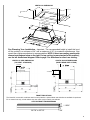 5
5
-
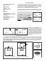 6
6
-
 7
7
-
 8
8
-
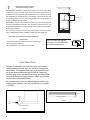 9
9
-
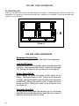 10
10
-
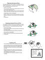 11
11
-
 12
12
-
 13
13
-
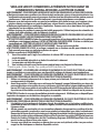 14
14
-
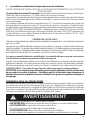 15
15
-
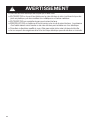 16
16
-
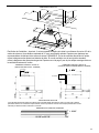 17
17
-
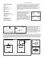 18
18
-
 19
19
-
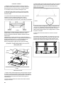 20
20
-
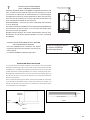 21
21
-
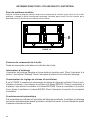 22
22
-
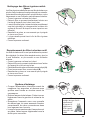 23
23
-
 24
24
-
 25
25
-
 26
26
-
 27
27
-
 28
28
-
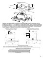 29
29
-
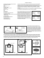 30
30
-
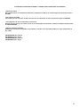 31
31
-
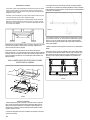 32
32
-
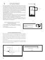 33
33
-
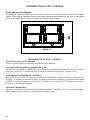 34
34
-
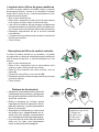 35
35
-
 36
36
-
 37
37
-
 38
38
-
 39
39
-
 40
40


Faber CRIS30SS300 Guía de instalación
- Categoría
- Campanas de cocina
- Tipo
- Guía de instalación
en otros idiomas
- français: Faber CRIS30SS300 Guide d'installation
- English: Faber CRIS30SS300 Installation guide
Artículos relacionados
-
Faber Cristal 30 SS 400 cfm Guía de instalación
-
-
-
-
-
Faber Stratus 36 SS Guía de instalación
-
-
-

