Allen + Roth 72-BVF11-BB-AR Guía de instalación
- Categoría
- Artículos sanitarios
- Tipo
- Guía de instalación

1
07-13-2020
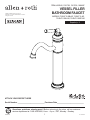
ITEM # 835542, 1361729, 1361728, 1864847
VESSEL FILLER
BATHROOM FAUCET
MODELS 72-BVF11-BB-AR, 72-BVF11-AR,
72-BVF11-BN-AR, 72-BVF11-BRZ-AR
Español p. 9
ALLEN + ROTH and logo design are
trademarks or registered trademarks of LF, LLC.
All rights reserved.
ATTACH YOUR RECEIPT HERE
Serial Number ___________________________ Purchase Date ___________________________
Questions, problems, missing parts? Before returning to the store, call our customer
service department at 1-866-439-9800, 8 a.m. - 8 p.m., EST, Monday - Sunday.
SM20280

2
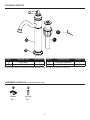
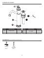
PART DESCRIPTION QUANTITY PART DESCRIPTION QUANTITY
A Faucet body 1 C Grid drain assembly 1
B Flange 1 D Allen wrench 1
Due to constant design and quality improvements, the product inside may look slightly different from the picture.
HARDWARE CONTENTS (not shown actual size)
AA BB
Washer Lock nut
Qty. 1 Qty. 1
PACKAGE CONTENTS
C
D
A
B

3
B
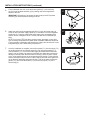
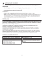
SAFETY INFORMATION
Please read and understand this entire manual before attempting to assemble, operate or install
the product.
CAUTION
• If you solder the joints during installation of the faucet, the seats, cartridges, and washers must be
removed before using a ame or the warranty will be voided on these parts.
• Cover the sink drain to avoid losing parts.
WARNING
• Protect your eyes with safety glasses when cutting or soldering water supply lines.
• NOTE: When making water line connections, HAND TIGHTEN. DO NOT OVERTIGHTEN. Do not
use PTFE pipe tape, plumber’s putty, pipe dope or any other type of sealing compound on water
inlet or threads. Additional compound is unnecessary. A watertight seal between the thread inlet
and supply tube is achieved by compression.
PREPARATION
Before beginning assembly of product, make sure all parts are present. Compare parts with package
contents list and hardware contents list. If any part is missing or damaged, do not attempt to assemble
the product. Contact customer service for replacement parts.
Estimated Assembly Time: 30 minutes
Tools Required for Assembly (not included): Adjustable Wrench, Slip Joint Pliers, Pipe Wrench,
Phillips Screwdriver, and Silicone.
Installation may vary depending on how the previous faucet was installed. Supplies necessary for the
installation of the faucet are not all included; however, they are available wherever plumbing supplies
are sold.
Prior to beginning installation, turn off the hot and cold water lines, then turn on the old faucet to
release built-up pressure. When installing the new faucet, hand tighten the connector nuts. DO NOT
OVERTIGHTEN. Connections that are too tight will reduce the integrity of the system.
PRODUCT SPECIFICATIONS
Maximum ow rate: 1.2 GPM (4.54 LPM) at 60 PSI Total weight of item: 3.23 lbs.
ASME A112.18.1/CSA B125 Ceramic cartridge
NSF/ANSI 61 Manufactured to include no more than 0.25%
weighted average lead content on wetted
surfaces
Oil-rubbed bronze nish - 835542
Chrome nish - 1361729
Brushed nickel nish - 1361728
Brushed bronze nish - 1864847

4
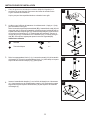
INSTALLATION INSTRUCTIONS
1.
Shut off the water at the supply valves under the sink or at the main water
supply. Disconnect the supply lines. Remove the existing faucet from the
sink.
Clean and dry the surface area where the new faucet will be mounted.
1
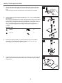
2.
Conrm that the hole in sink and/or countertop is 1.3 in. - 1.5 in. to accommodate
the new faucet.
Remove the preassembled lock nut (BB), and metal washer (AA) from the faucet
body (A). Before installation, make sure the ange (B) is on the bottom of the
faucet body (A). Insert the faucet body (A) through the mounting hole in the sink
(2.1). From underneath the sink, secure the faucet body (A) to the sink
using the washer (AA) and lock nut (BB). Use a wrench to tighten the lock
nut (BB).
Hardware used
2
BB
AA
2.1
A
B
AA
Washer x 1
BB
Lock nut x 1
3.
Remove the bottom gasket (3.1) and mounting nut (3.2) from the drain
assembly (C). Push the bottom gasket (3.1) down onto the top of the
mounting nut (3.2) and twist to attach together.
3
3.1
3.2
C
4.
Insert the drain assembly (C) into the drain hole in the sink (4.1). Ensure the top
gasket (4.2) rests securely between the top of the sink and the top of the drain
assembly (C).
4
4.2
C
4.1

5
INSTALLATION INSTRUCTIONS (continued)
5.
From underneath the sink, screw the bottom gasket (5.1) and mounting
nut (5.2) onto the drain assembly (C) by twisting until secure against the
bottom of the sink.
IMPORTANT: Remember to reconnect the drain body to the P-Trap drain
assembly (not included) before testing the faucet.
5
5.1
5.2
C
6.
Attach the end of each integrated supply line (6.1) from the faucet body (A)
to the hot and cold water supply valves (6.2). Thread the nut of the integrated
supply line (6.1) onto the outlet of the water supply valve and tighten with a
wrench. Do not overtighten. NOTE: The hot side inlet tube is indicated by a
label.
NOTE: Do not use PTFE pipe tape, plumber’s putty, pipe dope, or any other
type of sealing compound on the water inlets or threads. Additional compound
is not necessary. A watertight seal between the supply valve and the nut on the
integrated supply line is achieved by compression.
6
6.1
6.2
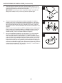
7.
Once the installation is complete, remove the aerator (7.1) from the spout (7.2)
on the faucet body (A) to ush the water lines. Do not lose the gasket (7.3)
from the aerator (7.1). Turn on the water supply and allow both hot and cold
water to run for at least one minute to ush away any debris that could cause
damage to internal parts. While the water is running, check for leaks. If leaks
occur, gently tighten the nut on the connection that is leaking. Fill the sink with
water to check the drain for leaks. If water is leaking from the drain, tighten the
nut on the drain assembly and empty the sink. Turn off the water, reinsert the
gasket (7.3), and screw the aerator (7.1) back onto the spout (7.2) of the
faucet body (A).
7
A
7.1
7.3
7.2

6
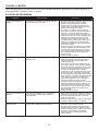
TROUBLESHOOTING
PROBLEM POSSIBLE CAUSE SOLUTION
Faucet leaks underneath
handle.
Bonnet has come loose or O-ring on cartridge
is dirty or twisted.
1. Move the handle to the OFF position.
Unscrew the handle screw and remove
the handle.
2. Tighten the bonnet by turning it clockwise.
Move the cartridge stem to the ON posi-
tion. The leak should stop draining out
from around the cartridge stem.
3. If the leak does not stop, shut off the water
supply. Remove the bonnet by turning it
counterclockwise. Lift out the cartridge
valve. Inspect the larger O-ring on the
cartridge bonnet and the smaller O-ring on
the cartridge stem. Remove any debris from
the O-rings. If either O-ring is twisted,
straighten it. If either O-ring is damaged,
replace the cartridge by calling customer
service.
4. Position the cartridge back into the faucet
body. Make sure the ridges on the two
sides of the cartridge bonnet t into the
grooves on the two sides of the faucet
body. Tightly screw the bonnet onto the
faucet body.
5. Reinstall the handle.
Water does not com-
pletely shut off.
Rubber valve seat is dirty, stuck, or broken. 1. Shut off the water supply.
2. Remove the handle from the faucet body.
Loosen the bonnet by turning it counter-
clockwise. Lift out the cartridge assembly.
3. Inspect the rubber valve seat in the faucet
body. If there is debris or brass scrap on
the surface of the seat, remove it. If the
rubber seat is stuck tightly in the water
inlet hole, push it gently with a ngertip so it
moves up and down smoothly. The spring
(smaller end up) must be placed back
underneath the valve seat. If the rubber
valve seat is worn out or broken, replace the
cartridge by calling customer service.
4. Position the cartridge back into the faucet
body. Make sure the ridges on the two
sides of the cartridge bonnet t into the
grooves on the two sides of the faucet
body. Tightly screw the bonnet onto the
faucet body.
5. Reinstall the handle.
Faucet leaks around
aerator.
The aerator is incorrectly tted, dirty, or small
parts inside the aerator are improperly
installed.
1. Remove the aerator cover from the spout
by turning it counterclockwise and remove
the aerator and gasket. Inspect the black
rubber gasket inside the aerator. The
rubber gasket should be at.
2. Reinstall the gasket and aerator, then replace
and tighten the aerator cover on the spout.
Faucet has an improper
water pattern.
The aerator is dirty or small parts inside the
aerator are improperly installed.
1. Remove the aerator cover from the spout
by turning it counterclockwise and remove
the aerator and gasket.
2. Gently ush the small parts inside the
aerator to clear away any debris.
3. Reinstall the gasket and aerator, then replace
and tighten the aerator cover on the spout.
Ensure all parts are straight and at.
CARE AND CLEANING
Clean periodically with a soft cloth. Avoid abrasive cleaners, steel wool, and harsh chemicals as these will dull the nish
and void your warranty.

7
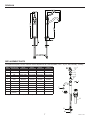
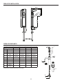
REPLACEMENT PARTS
For replacement parts, call our customer service department at 1-866-439-9800, 8 a.m. - 8 p.m., EST, Monday - Sunday.
PART DESCRIPTION PART # PART # PART # PART #
1361728 835542 1361729
1864847
1
Set screw
RP50002 RP50002 RP50002 RP50002
2
Handle
RP13542BN RP13542BB RP13542CH RP13542BRZ
3
Cap
RP80132BN RP80132BB RP80132CH RP80132BRZ
4
Bonnet nut
RP70274 RP70274 RP70274 RP70274
5
Cartridge and
screw
RP20096 RP20096 RP20096 RP20096
6
Allen wrench
RP70221 RP70221 RP70221 RP70221
7
Aerator
RP30213BN RP30213BB RP30213CH RP30213BRZ
8
Flange
RP80618BN RP80618BB RP80618CH RP80618BRZ
9
Washer
RP70228 RP70228 RP70228 RP70228
10
Lock nut
RP56071 RP56071 RP56071 RP56071
11
Grid drain
assembly
RP40300BN RP40300BB RP40300CH RP40300BRZ
Note: Appearance of actual parts may vary from drawing.
Printed in China
1
2
3
4
5
9
10
8
7
11
6
ROUGH-IN

8
LIMITED LIFETIME WARRANTY
The distributor warrants to the original consumer purchaser this product to be free from defects in material and workmanship
under normal use in residential applications. At its option, the Company will provide repair parts or replace defective
product when the product is used in accordance with the manufacturer’s specications.
The distributor provides a limited 5-year warranty on the nish of this product to the original purchaser. At its option, the
distributor will provide repair parts or replace defective product when the product is used in accordance with the manufacturer’s
specications. Use of mild abrasive, abrasive or chemical cleaners may damage the nish of the faucet. We recommend
cleaning your faucet with a soft cloth, moistened with water. Damage resulting from the use of abrasive or chemical
cleaners SHALL VOID THIS WARRANTY.
This warranty is not applicable to any products or parts of products where damage is caused by use of non-genuine parts;
is due to installation error, product misuse, negligence or faulty maintenance; or where the product is not installed according
to local building codes.
This warranty excludes labor charges or damage incurred during installation, repair or replacement, and any indirect,
incidental or consequential damages, losses, injury or costs of any nature. This warranty is in lieu of and excludes all other
warranties, conditions and guarantees, whether expressed or implied, including without restriction those of merchantability
or tness of use.
Liability under this warranty will not exceed the purchase price for the product claimed to be defective by the original
consumer purchaser. Some states or provinces do not allow the exclusion or limitation of consequential damages so the
above limitations or exclusions may not apply. This warranty gives you specic legal rights and you may also have other
rights which vary from state to state, or province to province.
Inquiries regarding warranty claims can be directed to 1-866-439-9800, 8 a.m. - 8 p.m., EST, Monday - Sunday.

9
ARTÍCULO # 835542, 1361729, 1361728, 1864847
GRIFO PARA BAÑO
PARA EL LLENADO
DEL LAVABO
MODELOS 72-BVF11-BB-AR, 72-BVF11-AR,
72-BVF11-BN-AR, 72-BVF11-BRZ-AR
ALLEN + ROTH y el diseño del logo son marcas
comerciales o marcas registradas de LF, LLC.
Todos los derechos reservados.
¿Preguntas, problemas, piezas faltantes? Antes de volver a la tienda, llame a nuestro
Departamento de Servicio al Cliente al 1-866-439-9800, de lunes a domingo de 8 a.m. a 8 p.m.,
hora estándar del Este.
ADJUNTE SU RECIBO AQUÍ
Número de serie _________________________ Fecha de compra ________________________
NSF/ANSI 61
SIN
PLOMO
CUMPLE
CON ADA

10
ADITAMENTOS (no se muestran en tamaño real)
AA BB
Arandela Tuerca
de bloqueo
Cant. 1 Cant. 1
CONTENIDO DEL PAQUETE
PARTE DESCRIPCIÓN CANTIDAD PARTE DESCRIPCIÓN CANTIDAD
A Cuerpo del grifo 1 C
Ensamble de desagüe
con rejilla
1
B Brida 1 D Llave Allen 1
Debido a las constantes mejoras de diseño y calidad, es posible que el producto en el interior se vea ligeramente diferente de la imagen.
C
D
A
B

11
B
INFORMACIÓN DE SEGURIDAD
Lea y comprenda completamente este manual antes de intentar ensamblar, usar o instalar el producto.
PRECAUCIÓN
• Si suelda las juntas durante la instalación del grifo, se deben retirar los asientos, los cartuchos y las arandelas
antes de usar la llama. De lo contrario, se anulará la garantía de dichas piezas.
• Cubra el desagüe para evitar que se pierdan piezas.
ADVERTENCIA
• Proteja los ojos con gafas de seguridad al cortar o soldar las líneas de entrada de agua.
• NOTA: al realizar la conexión de la línea de agua, APRIETE A MANO. NO APRIETE DEMASIADO. No use
cinta para tubería de PTFE, masilla de plomero, aditivos para tubos ni ningún otro compuesto sellador en
entradas de agua o roscas. No necesita compuestos adicionales. Se logra un sellado hermético entre la
entrada roscada y la tubería de suministro mediante compresión.
PREPARACIÓN
Antes de comenzar a ensamblar el producto, asegúrese de tener todas las piezas. Compare las piezas con la lista
del contenido del paquete y la lista de aditamentos. No intente ensamblar el producto si falta alguna pieza o si estas
están dañadas. Póngase en contacto con el Departamento de Servicio al Cliente para obtener piezas de repuesto.
Tiempo estimado de ensamblaje: 30 minutos
Herramientas necesarias para el ensamblaje (no se incluyen): llave inglesa ajustable, pinzas para juntas
deslizantes, llave para tubos, destornillador Phillips, y silicona.
La instalación puede variar según cómo se instaló el grifo anterior. No se incluyen todos los materiales
necesarios para la instalación del grifo; no obstante, estos están disponibles en cualquier lugar donde se
vendan artículos de plomería.
Antes de comenzar la instalación, cierre las líneas de entrada de agua fría y caliente, y luego abra el grifo viejo
para liberar la presión acumulada. Al instalar el nuevo grifo, primero apriete a mano las tuercas del conector. NO
APRIETE DEMASIADO. Las conexiones que estén muy apretadas reducirán la integridad del sistema.
ESPECIFICACIONES DEL PRODUCTO
Caudal de ujo máximo: 4,54 LPM (1,2 GPM) a 60 PSI Peso total del artículo: 1,5 kg
Cumple con la norma ASME A112.18.1/CSA B125 Cartucho sin cerámica
NSF/ANSI 61 Fabricado para que no incluya más de 0,25 % de
contenido promedio en peso de plomo para supercies
con agua
Acabado de bronce aceitado - 835542
Acabado cromado - 1361729
Acabado de níquel cepillado - 1361728
Acabado de bronce cepillado - 1864847

12
INSTRUCCIONES DE INSTALACIÓN
1.
Cierre el agua en las válvulas de suministro debajo del fregadero o el
suministro de agua principal. Desconecte las líneas de entrada. Retire
el grifo existente del lavamanos.
Limpie y seque el área supercial donde se colocará el nuevo grifo.
1
2.
Conrme que el oricio en el lavamanos o la cubierta sea de 1,3 pulg. a 1,5 pulg.
para acomodar el nuevo grifo.
Retire la tuerca de seguridad preensamblada (BB) y la arandela de metal (AA) del
cuerpo del grifo (A). Antes de la instalación, asegúrese de que la brida (B) esté en
la parte inferior del cuerpo del grifo (A). Inserte el cuerpo del grifo (A) por el oricio
de montaje en el lavamanos (2.1). Desde debajo del lavamanos, asegure el
cuerpo del grifo (A) al lavamanos con la arandela (AA) y la tuerca de seguri-
dad (BB). Use una llave inglesa para apretar la tuerca de seguridad (BB).
Aditamentos utilizados
2
BB
AA
2.1
A
B
AA
Arandela x 1
BB
Tuerca de bloqueo x 1
3.
Retire la empaquetadura inferior (3.1) y la tuerca de montaje (3.2) del ensamble
del desagüe (C). Empuje la empaquetadura inferior (3.1) hacia abajo en la parte
superior de la tuerca de montaje (3.2) y gírelas juntas.
3
3.1
3.2
C
4.
Inserte el ensamble del desagüe (C) en el oricio del desagüe en el lavamanos
(4.1). Asegúrese de que la empaquetadura superior (4.2) se asiente de manera
segura entre la parte superior del lavamanos y la parte superior del ensamble
del desagüe (C).
4
4.2
C
4.1

13
INSTRUCCIONES DE INSTALACIÓN (Continuación)
5.
Desde debajo del lavamanos, atornille la empaquetadura inferior (5.1) y la
tuerca de montaje (5.2) en el ensamble del desagüe (C) girándola hasta que
quede segura contra la parte inferior del lavamanos.
IMPORTANTE: recuerde conectar el cuerpo del desagüe al ensamble del
desagüe de la trampa en P (no se incluye) antes de probar el grifo.
5
5.1
5.2
C
6.
Conecte el extremo de cada línea de suministro integrada (6.1) desde el
cuerpo del grifo (A) a las válvulas de suministro de agua fría y caliente (6.2).
Enrosque la tuerca de la línea de suministro integrada (6.1) en las salidas
de las válvulas de suministro de agua y apriete con una llave. No apriete
demasiado. NOTA: El tubo de entrada de agua caliente se identica con una
etiqueta.
NOTA: No use cinta para tubería de PTFE, masilla de plomero, aditivos para
tubos ni ningún otro compuesto sellador en entradas de agua o roscas. No
necesita compuestos adicionales. Se logra un sellado hermético entre la
entrada roscada y la línea de entrada mediante compresión.
6
6.1
6.2
7.
Una vez completada la instalación, retire el aireador (7.1) del tubo surtidor
(7.2) en el cuerpo del grifo (A) para descargar las tuberías de agua. No
suelte la empaquetadura (7.3) del aireador (7.1). Abra el suministro de agua
y deje correr el agua fría y caliente durante al menos un minuto para eliminar
cualquier residuo que pueda dañar las piezas internas. Revise que no haya
fugas mientras el agua corre. Si se producen fugas, apriete suavemente la
tuerca en la conexión que esté goteando. Llene el lavamanos con agua para
vericar que el desagüe no tenga fugas. Si sale agua del desagüe, apriete la
tuerca del ensamble de desagüe y vacíe el lavamanos. Cierre el agua, vuelva
a insertar la empaquetadura (7.3) y atornille el aireador (7.1) nuevamente en
el tubo surtidor (7.2) del cuerpo del grifo (A).
7
A
7.1
7.3
7.2

14
SOLUCIÓN DE PROBLEMAS
PROBLEMA CAUSA POSIBLE SOLUCIÓN
El grifo gotea debajo de la
manija.
El casquete se ha soltado o la junta de anillo del
cartucho está sucia o retorcida.
1. Mueva la manija a la posición OFF. Desenrosque
el tornillo de la manija y retire la manija.
2. Apriete el casquete girándolo en sentido
horario. Mueva el vástago del cartucho a la
posición ON. La fuga debe dejar de drenarse
alrededor del vástago del cartucho.
3. Si la fuga no se detiene, cierre la salida de
agua. Retire el casquete girándolo en sentido
antihorario. Levante la válvula del cartucho.
Inspeccione la junta de anillo más grande en el
casquete del cartucho y la junta de anillo más
pequeña en el vástago del cartucho. Retire
cualquier residuo de las juntas de anillo. Si
cualquiera de las juntas de anillo está torcida,
alísela. Si cualquiera de las juntas de anillo
está dañada, reemplace el cartucho llamando
al servicio al cliente.
4. Coloque el cartucho nuevamente en el cuerpo
del grifo. Asegúrese de que las estrías en los
dos lados del casquete del cartucho encajen
en las ranuras en los dos lados del cuerpo del
grifo. Atornille rmemente el casquete en el
cuerpo del grifo.
5. Vuelva a instalar la manija.
El agua no se cierra por
completo.
El asiento de la válvula de goma está sucio,
atascado o roto.
1. Cierre la llave de paso de agua.
2. Retire la manija del cuerpo del grifo. Aoje el
casquete girándolo en sentido antihorario.
Levante el cartucho.
3. Inspeccione el asiento de la válvula de goma
en el cuerpo del grifo. Si hay restos o restos de
latón en la supercie del asiento, retírelo. Si el
asiento de goma está atascado rmemente en
el oricio de entrada de agua, empújelo
suavemente con la punta del dedo para que se
mueva hacia arriba y hacia abajo suavemente.
El resorte (extremo más pequeño hacia arriba)
debe colocarse nuevamente debajo del asiento
de la válvula. Si el asiento de la válvula de
goma está desgastado o roto, reemplace el
cartucho llamando al servicio al cliente.
4. Coloque el cartucho nuevamente en el cuerpo
del grifo. Asegúrese de que las estrías en los
dos lados del casquete del cartucho encajen
en las ranuras en los dos lados del cuerpo del
grifo. Atornille rmemente el casquete en el
cuerpo del grifo.
5. Vuelva a instalar la manija.
El grifo gotea alrededor del
aireador.
El ltro está mal instalado, sucio o las piezas
pequeñas dentro del ltro están instaladas
incorrectamente.
1. Retire el ltro del surdidor girándolo en sentido
antihorario y retire la junta. Inspeccione la junta
de goma negra dentro del ltro. La junta de
goma debe ser plana.
2. Vuelva a instalar la junta y el ltro, luego vuelva
a colocar y apriete el ltro en el surtidor.
El grifo tiene un patrón de
agua incorrecto.
El ltro está sucio o las piezas pequeñas dentro
del ltro están instaladas incorrectamente.
1. Retire el ltro del surtidor girándolo en sentido
antihorario y retire el ltro y la junta.
2. Enjuague suavemente las piezas pequeñas
dentro del ltro para limpiar cualquier residuo.
3. Vuelva a instalar la junta y el ltro, luego vuelva
a colocar y apriete el ltro en el surtidor.
Asegúrese de que todas las piezas estén
rectas y planas.
CUIDADO Y LIMPIEZA
Limpie periódicamente con un paño suave. Evite utilizar limpiadores abrasivos, lana de acero y químicos agresivos, ya
que pueden dañar el acabado y anular su garantía.

15
PIEZAS DE REPUESTO
Para piezas de repuesto, llame a nuestro departamento de servicio al cliente al 1-866-439-9800, de 8 a.m. a 8 p.m., EST, de lunes a domingo.
PIEZA DESCRIPCIÓN Nº DE PIEZA Nº DE PIEZA Nº DE PIEZA Nº DE PIEZA
1361728 835542 1361729
1864847
1
Tornillo de ajuste
RP50002 RP50002 RP50002 RP50002
2
Manija
RP13542BN RP13542BB RP13542CH RP13542BRZ
3
Gorra
RP80132BN RP80132BB RP80132CH RP80132BRZ
4
Tuerca del
bonete
RP70274 RP70274 RP70274 RP70274
5
Cartucho y
tornillo
RP20096 RP20096 RP20096 RP20096
6
Llave Allen
RP70221 RP70221 RP70221 RP70221
7
Aireador
RP30213BN RP30213BB RP30213CH RP30213BRZ
8
Brida
RP80618BN RP80618BB RP80618CH RP80618BRZ
9
Arandela
RP70228 RP70228 RP70228 RP70228
10
Tuerca de
bloqueo
RP56071 RP56071 RP56071 RP56071
11
Montaje de
drenaje
RP40300BN RP40300BB RP40300CH RP40300BRZ
Nota: El aspecto de las piezas reales puede variar del dibujo.
1
2
3
4
5
9
10
8
7
11
6
DIBUJO DE INSTALACIÓN

16
Impreso en China
GARANTÍA LIMITADA DE POR VIDA
El distribuidor garantiza al comprador/consumidor original que este producto está libre de defectos en cuanto a los materiales y la mano de obra
en condiciones de uso normales en aplicaciones residenciales. A su elección, la Compañía proporcionará piezas de repuesto o reemplazará un
producto defectuoso si el producto se utilizó de acuerdo con las especicaciones del fabricante.
El distribuidor le brinda al comprador original una garantía limitada de 5 años para el acabado de este producto. A su elección, el distribuidor
proporcionará piezas de repuesto o reemplazará un producto defectuoso si el producto se utilizó de acuerdo con las especicaciones del
fabricante. El uso de limpiadores abrasivos suaves, abrasivos o químicos puede dañar el acabado del grifo. Le recomendamos que limpie
el grifo con un paño suave y humedecido con agua. El daño ocasionado por el uso de limpiadores abrasivos o químicos ANULARÁ ESTA
GARANTÍA.
Esta garantía no se aplica a productos o piezas de productos si el daño fue ocasionado por el uso de piezas no originales; o se deba a un error
de instalación, al mal uso del producto, a negligencia o al mantenimiento inadecuado; o en caso de que el producto no se haya instalado
de acuerdo con los códigos de construcción locales.
Esta garantía no incluye los cargos por mano de obra o los daños ocasionados durante la instalación, la reparación o el reemplazo, ni las
lesiones, las pérdidas o los daños indirectos, accidentales o resultantes, ni los costos de ninguna naturaleza. Esta garantía reemplaza y excluye
todas las demás garantías y condiciones, expresas o implícitas, incluidas sin restricción aquellas de comerciabilidad o uso adecuado.
La responsabilidad bajo esta garantía no superará el precio de compra del producto que se reclama como defectuoso pagado por el cliente o
comprador original. Algunos estados o provincias no permiten la exclusión o limitación de los daños accidentales o resultantes, de modo que
es posible que no se apliquen las exclusiones o limitaciones mencionadas anteriormente. Esta garantía le otorga derechos legales especícos
y es posible que también tenga otros derechos que varían según el estado o la provincia.
Las consultas sobre reclamos por garantías se pueden hacer al 1-866-439-9800, de lunes a domingo de 8 a.m. a 8 p.m., hora estándar del Este.
-
 1
1
-
 2
2
-
 3
3
-
 4
4
-
 5
5
-
 6
6
-
 7
7
-
 8
8
-
 9
9
-
 10
10
-
 11
11
-
 12
12
-
 13
13
-
 14
14
-
 15
15
-
 16
16


Allen + Roth 72-BVF11-BB-AR Guía de instalación
- Categoría
- Artículos sanitarios
- Tipo
- Guía de instalación
En otros idiomas
Documentos relacionados
Otros documentos
-
NEOPERL 37.0085.98 Guía de instalación
-
 Mirabelle MIRWSCPT100ORB Guía de instalación
-
Glacier Bay HD67543W-6001 Guía de instalación
-
-
-
ProFlo PFWSC2860BN Guía de instalación
-
Glacier Bay 67664W-6001 Guía de instalación
-
-
-
