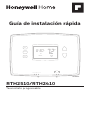
Honeywell Home RTH2410 Guía de instalación
- Tipo
- Guía de instalación
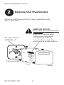
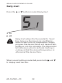
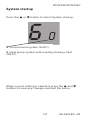
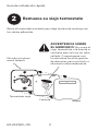
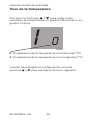
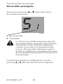
El Honeywell Home RTH2410 es un termostato programable fácil de usar que te ayuda a mantener tu hogar cómodo y eficiente energéticamente. Con su pantalla grande y retroiluminada, es fácil de leer, incluso en la oscuridad. Puedes programar hasta 4 períodos de tiempo y temperaturas para cada día de la semana, para que tu hogar esté siempre a la temperatura perfecta cuando lo necesites. El RTH2410 también tiene una función de retención que te permite mantener temporalmente una temperatura diferente a la programada.
El Honeywell Home RTH2410 es un termostato programable fácil de usar que te ayuda a mantener tu hogar cómodo y eficiente energéticamente. Con su pantalla grande y retroiluminada, es fácil de leer, incluso en la oscuridad. Puedes programar hasta 4 períodos de tiempo y temperaturas para cada día de la semana, para que tu hogar esté siempre a la temperatura perfecta cuando lo necesites. El RTH2410 también tiene una función de retención que te permite mantener temporalmente una temperatura diferente a la programada.


-
 1
1
-
 2
2
-
 3
3
-
 4
4
-
 5
5
-
 6
6
-
 7
7
-
 8
8
-
 9
9
-
 10
10
-
 11
11
-
 12
12
-
 13
13
-
 14
14
-
 15
15
-
 16
16
-
 17
17
-
 18
18
-
 19
19
-
 20
20
-
 21
21
-
 22
22
-
 23
23
-
 24
24
-
 25
25
-
 26
26
-
 27
27
-
 28
28
-
 29
29
-
 30
30
-
 31
31
-
 32
32
-
 33
33
-
 34
34
-
 35
35
-
 36
36
-
 37
37
-
 38
38
-
 39
39
-
 40
40
-
 41
41
-
 42
42
-
 43
43
-
 44
44
-
 45
45
-
 46
46
-
 47
47
-
 48
48


Honeywell Home RTH2410 Guía de instalación
- Tipo
- Guía de instalación
El Honeywell Home RTH2410 es un termostato programable fácil de usar que te ayuda a mantener tu hogar cómodo y eficiente energéticamente. Con su pantalla grande y retroiluminada, es fácil de leer, incluso en la oscuridad. Puedes programar hasta 4 períodos de tiempo y temperaturas para cada día de la semana, para que tu hogar esté siempre a la temperatura perfecta cuando lo necesites. El RTH2410 también tiene una función de retención que te permite mantener temporalmente una temperatura diferente a la programada.