
Installation
INSTRUCTIONS
Thermador Masterpiece
®
Island Hood
THERMADOR.COM

THERMADOR.COM
Installation
INSTRUCTIONS
Thermador Masterpiece
®
Island Hood
Table of Contents (English) ................................................................... 3
Table de Matières (Français) ................................................................. 23
Índice de Capítulos (Español)................................................................ 43
Models |
Modèles |
Modelos:
HMIB36WS
HMIB42WS

Installation Instructions English | 3 |
Table of
Contents
Safety .................................................................................. 4
Important Safety Instructions ..................................... 4
Advance Planning .............................................................. 7
Before You Begin ........................................................ 7
General Information ................................................... 8
Installation Preparation....................................................... 9
Installation Considerations ......................................... 9
Electrical Requirements............................................... 10
Ductwork Preparation ................................................ 10
Installation Instructions ............................................... 13
Electrical Connection .................................................. 17
Remote Control Installation (optional) ....................... 18
Duct Cover Extension (optional)................................. 19
Recirculating Kit (optional).......................................... 20
Charcoal Filter Replacement (optional)...................... 21
Installer Checklist ............................................................... 22
Before Calling Service ........................................................ 22
Product Data Rating Plate .......................................... 22
Service, Parts & Accessories ................................ back page
Safety
Definitions
WARNING
This indicates that death or serious injuries may occur as a
result of non-observance of this warning.
CAUTION
This indicates that minor or moderate injuries may occur
as a result of non-observance of this warning.
NOTICE: This indicates that damage to the appliance or
property may occur as a result of non-compliance with this
advisory.
Note: This alerts you to important information and/or tips.
This THERMADOR® appliance is made by
BSH Home Appliances Corporation
1901 Main Street, Suite 600
Irvine, CA 92614
Questions?
1-800-735-4328
www.thermador.com
We look forward to hearing from you!

Installation InstructionsEnglish | 4 |
Safety
IMPORTANT SAFETY INSTRUCTIONS
READ AND SAVE THESE INSTRUCTIONS
INSTALLER: Save these instructions for the local electrical
inspector’s use. Please leave these instructions with this
unit for the owner. Show the owner the location of the
circuit breaker or fuse. Mark it for easy reference.
OWNER: Please retain these instructions for future
reference.
WARNING
If the information in this manual is not followed exactly,
personal injury.
WARNING
If the information in this manual is not followed
-
ty damage, personal injury or death.
-
vapors and liquids in the vicinity of this or any other
apppliance.
- WHAT TO DO IF YOU SMELL GAS
DO NOT try to light any appliance.
DO NOT touch any electrical switch.
DO NOT use any phone in your building.
Immediately call your gas supplier from a
neighbor’s phone. Follow the gas supplier’s
instructions.
department.
- Installation and service must be performed by an
authorized servicer, service agency or the gas supplier.
WARNING
Turn off power circuit at service panel and lock out panel
before wiring this appliance. Requirement: 120 VAC, 60
Hz 15 A. Allow the appliance to cool after the power has
been turned off before servicing the appliance.
WARNING
Automatically Operated Device
To reduce the risk of injury disconnect from power supply
before servicing.
WARNING
TO REDUCE THE RISK OF FIRE, ELECTRIC SHOCK,
OR INJURY TO PERSONS, OBSERVE THE
FOLLOWING:
Use this unit only in the manner intended by the
manufacturer. If you have questions, contact the
manufacturer at the address or telephone number
listed on the back page.
Before servicing or cleaning unit, switch power off at
service panel and lock the service disconnecting
means to prevent power from being switched on
accidentally. When the service disconnecting means
cannot be locked, securely fasten a prominent
warning device, such as a tag, to the service panel.
WARNING
DO NOT repair or replace any part of the appliance
Improper installation, service or maintenance can cause
injury or property damage. Refer to this manual for
guidance. All other servicing should be done by an
authorized servicer.
WARNING
ELECTRICAL SHOCK HAZARD
DO NOT remove connections.
DO NOT use an extension cord.
Failure to follow these instructions can

Installation Instructions English | 5 |
IMPORTANT SAFETY INSTRUCTIONS
READ AND SAVE THESE INSTRUCTIONS
Grounding Instructions
WARNING
Improper grounding can result in a risk of electric shock.
This appliance must be grounded. In the event of an electri-
cal short circuit, grounding reduces the risk of electric shock
by providing an escape wire for the electric current.
Be sure your appliance is properly installed and grounded
and grounding must comply with all applicable codes.
If required by the National Electrical Code (or Canadian
Electrical Code), this appliance must be installed on a sepa-
rate branch circuit.
WARNING
DO NOT use
this appliance with any solid state speed device.
Safety Codes and Standards
This appliance complies with one or more of the following
Standards:
UL 507, The Standard for the Safety of Electric Fans
CSA C22.2 No. 113, Fans and Ventilators
It is the responsibility of the owner and the installer to de-
termine if additional requirements and/or standards apply
CAUTION
Unit is heavy and requires at least two people
or proper equipment to move and install.
Hidden surfaces may have sharp edges. Use
caution when handling the appliance. Failure
to do so may result in property damage or
personal injury.
WARNING
State of California Proposition 65 Warnings:
This product can expose you to chemicals including vinyl
chloride, which is known to the State of California to
cause cancer and birth defects or other reproductive
harm. For more information go to
www.P65Warnings.ca.gov.
Never modify or alter the construction of the appliance.
For example, do not remove panels, wire covers or
brackets/screws.
CAUTION
For general ventilating use only. DO NOT use to exhaust
hazardous or explosive materials and vapors.
WARNING
Remove all tape and packaging before using the
appliance. Destroy the packaging after install. Never allow
children to play with packaging material.
WARNING
TO REDUCE THE RISK OF FIRE, ELECTRIC SHOCK,
OR INJURY TO PERSONS, OBSERVE THE
FOLLOWING:
Installation work and electrical wiring must be done
construction.
fuel burning equipment to prevent back drafting.
Follow the heating equipment manufacturer’s
guideline and safety standards such as those
published by the National Fire Protection
Association (NFPA), and the American Society for
Heating, Refrigeration and Air Conditioning
Engineers (ASHRAE), and the local code authorities.
When cutting or drilling into wall or ceiling, do not
damage electrical wiring and other hidden utilities.
Ducted fans must always be vented to the outdoors.

Installation InstructionsEnglish | 6 |
IMPORTANT SAFETY INSTRUCTIONS
READ AND SAVE THESE INSTRUCTIONS
WARNING
TO REDUCE THE RISK OF A RANGE TOP GREASE
FIRE:
Never leave surface units unattended at high
settings.
Boilovers cause smoking and greasy spillovers that
may ignite. Heat oils slowly on low or medium
settings.
Always turn hood ON when cooking at high heat
Cherries Jubilee, Peppercorn Beef Flambe).
Clean ventilating fans frequently. Grease should
Use proper pan size. Always use cookware
appropriate for the size of the surface element.
WARNING
TO REDUCE THE RISK OF INJURY TO PERSONS IN
THE EVENT OF A RANGE TOP GREASE FIRE,
OBSERVE THE FOLLOWING:
a
sheet, or metal tray, then turn off the burner. BE
go out immediately, EVACUATE AND CALL THE
FIRE DEPARTMENT.
NEVER PICK UP A FLAMING PAN - you may get
burned.
DO NOT USE WATER, including wet dishcloths or
towels - a violent steam explosion will result.
Use an extinguisher ONLY if:
a) You know you have a class ABC extinguisher,
and you already know how to operate it.
b)
it started.
c)
d)
a
Based on “Kitchen Fire Safety Tips” published by NFPA.

Installation Instructions English | 7 |
Advance Planning
Before You Begin
CAUTION
Before installing, turn power OFF at the service panel.
Lock service panel to prevent power from being turned
ON accidentally.
Parts Included
Hood assembly (LED lamps already
installed)
Blower housing
Top and lower duct covers
Structure horizontal supports
Structure upper/lower
vertical supports
Fastener assortment*
* Hardware provided is for mounting through standard
thickness drywall or plaster into wood studs. Installers
are responsible to provide hardware for other types of
mounting situations.
NOTE:
cover and hood assembly prior to the start of the installa-
tion. Use one hand to maintain the assembly/duct cover
Tools and Parts Needed
Ducting as needed (refer to Equivalent Duct Lengths
for Commonly Used Transitions Table)
Aluminum tape (DO NOT use duct tape)
1/2’’ (13 mm) Conduit if required (follow local codes)
1’’ (25.4 mm) Strain relief
Ducting as needed
Blower
Flat head and Phillips screwdrivers
Drill with
3
16’’ (4.76 mm) drill bit
Circular saw or jigsaw
3/8’’ (9.52 mm) nut driver or socket and ratchet
Wire stripper
Protective work gloves
IMPORTANT: DO NOT throw away any packaging until
appliance is fully installed.
Optional accessories available for separate
purchase.
Refer to www.thermador.com for more details.
CHXTHMIB – Telescopic Duct Cover Extension Kit
RECHMIB – Recirculating Kit
CHFHMCD – Charcoal Filter Replacement Kit
REMCPW – Built-In Remote Control Accessory

Installation InstructionsEnglish | 8 |
General Information
Overall Dimensions
HMIB36WS and HMIB42WS
This model series is 23
3
16’’ (588 mm) in depth and feature
brushed stainless-steel canopy with LED lights.
inches (mm)
Ø 8"
(200)
36" (914)
42" (1067)
27"
(686)
18
3
/
8
"
(467)
2
3
/
4
"
(70)
DUCTED
MIN: 30” (762)
MAX:
45
1
/
16
"(1144)
RECIRCULATING
MIN: 30” (762)
MAX:
50
1
/
16
"(1271)
13
4
/
16
"
(336)
14
7
/
8
"
(378)

Installation Instructions English | 9 |
Installation Preparation
Installation Considerations
Clearances and requirements
Hood installation height above a cooktop, rangetop or
range can vary. To obtain the necessary installation
height above a cooktop, rangetop or range, consult the
appliance’s installation manual.
18
3
/
8
" (467)
8
1
/
4
"
(209)
30" (762) min over
a electric cooktop
30" (762) min over
a gas cooktop
Hood Width
The hood width should be no less than the width of the
cooking surface. For proper performance, the housing
must cover the entire cooking surface. Where space is
not restricted, a wider hood can be used to increase
capture area.
For proper performance, the hood must be centered
horizontally above the cooking surface.
Distance From Cooking Surface
For gas cooktop & range installations: Mount the hood
so the bottom is at least 30” (76.2 cm) above the cooking
surface.
For electric/induction cooktop & range installations:
Mount the hood so the bottom is at least 30” (76.2 cm)
above the cooking surface.
NOTICE: The hood could incur some damage from heat
if a THERMADOR MASTERPIECE
®
series cooktop is opera-
ted with multiple burners at high settings under a hood that
is installed at minimum clearances.
Unit Weight
This vent hood is heavy. Adequate structure and support
must be provided in all types of installations.
When calculating the load for the housing support
system, be sure to consider the weight of the
ventilation unit.
Unit Weight
36’’ (91.4 cm) 91 lb (41.3 kg)
42’’ (106.7 cm) 96.5 lb (43.8 kg)
IMPORTANT:
The supplied weights address only the ventilation unit and
blower. Installer must account for weight of any materials
of construction when calculating the total dead weight
load of installation, including but not limited to: wall, tile,
incorporated architectural and structural items. It is the
responsibility of the owner and the installer to determine if
installations.

Installation InstructionsEnglish | 10 |
Electrical Requirements
The unit requires a 120V AC, 60Hz. 15A branch circuit.
The hood should only be connected to a dedicated circuit
(with ground) that has been installed according to relevant
regulations.
Check your local building codes for proper method of ins-
tallation. In the U.S., if there are no applicable local codes,
this unit should be installed in accordance with the National
Electric Code ANSI/NFPA No. 70, Current Issue. In Canada,
installation must be in accordance with the CAN 1- B149.1
and .2 - Installation Codes for Gas Burning Appliances and/
or local codes.
The appliance must be grounded. In the event of an elec-
trical short circuit, grounding reduces the risk of electric
shock by providing a wire that allows the electric current to
escape.
WARNING
The appliance must be grounded.
Electrical Data on the Data Rating Label
Data, including the model and serial number, is located
on the product data rating label inside the appliance,
Ductwork Preparation
Discharge Direction
The exhaust air is discharged upwards through a duct.
The hood can be mounted only with a vertical discharge.
Ducting Recommendations
Proper performance is dependent upon proper ducting.
Local building codes may require the use of make-up air
systems when using ducted ventilation systems greater than
responsibility of the owner and the installer to determine if
installations.
DO NOT USE FLEXIBLE DUCT; it creates back pressure/
air turbulence and reduces performance. Always use metal
ductwork.
Always install a metal vent cover where the ductwork exits
the house. Hood must be vented to the outside of building
only.
COLD WEATHER installations should have an additional
backdraft damper installed to minimize backward cold air
-
tion of outside temperatures as part of the ductwork. The
damper should be on the cold air side of the thermal break.
The break should be as close as possible to where the duc-
ting enters the heated portion of the house.
MAKE-UP AIR: Local building codes may require the use of
make-up air systems when using ducted ventilation systems
responsibility of the owner and the installer to determine if
installations.
For safety reasons, ducting should vent directly outdoors
(not into an attic, underneath the house, into the garage or
into any enclosed space).
THERMADOR
®
recommends not exceeding 50 equivalent
length (ft) (15.24 m) of duct.
Keep duct runs as short and straight as possible.
Back to back elbows and “S” turns give very poor delivery
and are not recommended.
A short straight length of duct at the inlet of a remote
blower gives the best delivery.
Hoods are supplied with a 8” (203 mm) round transition. A
locally supplied transition is required for other sizes.
Use “Equivalent Duct Lengths for Commonly Used Transi-
tions” on page 11 to compute permissible lengths for duct
runs to outdoors.

Installation Instructions English | 11 |
Equivalent Duct Lengths for Commonly
Used Transitions
Size (in)
Eq uivalent
Length (ft)
Size (in)
Eq uivalent
Length (ft)
61.2
61
0
80.7
10 0.6
3¼" x 10", straight N/A1
3¼" x 10", Center
reverse elbow, right
N/
A2
5
3¼" x 14", straight N/A0.7
3¼" x 10", Left
reverse elbow
N/
A1
5
3¼" x 10", Right
reverse elbow
N/
A2
5
612
62
86
82
10
10 2
65
62
2
5
83
82
2
2
10
10
3¼" x 10",
90° elbow, round
N/A5
2’ long, 3¼" x 10" exN/A 20
3¼" x 10",
45° elbow, round
N/A15
3¼" x 10", Flat elbowN/A 20
61
810
82
3¼" x 10", Roof jack
and shutter
N/A
65
61
0
NOTE: These commonly used installation parts can be purchased at a
local hardware store. Thermador does not manufacture all these parts.
Round wall cap
Round roof cap
3¼" x 10" to round
90° elbow,
Duct Piece
3¼" x 10" Center
reverse elbow, left
15N/A
Round to 3¼" x 10"
3¼" x 10" to round
Round to 3¼" x 10"
90° elbow,
Duct Piece
Smooth, straight
90° elbow, round
45° elbow, round

Installation InstructionsEnglish | 12 |
RECIRCULATING MODE VENTING THROUGH THE CEILING
A. 8” round transition
B. 8” round duct system
C. Recirculating kit
A
B
C
A
B
NOTE:
Venting Methods
This hood is factory set for venting through the roof (vertical
discharge). A 8” (203 mm) round duct system is needed for
installation (not included).
NOTE: Flexible duct is not recommended. Flexible
ductwork creates back pressure and air turbulence that
greatly reduce performance.
Vent system can terminate either through the roof.
Always install a metal vent cover where the ductwork exits
the house.
For Non-Vented (recirculating) Installations
If it is not possible to vent cooking fumes and vapors to
the outside, the hood can be used in the non-vented
(recirculating) version, using the recirculating kit . Fumes
and vapors are recycled through the round grid.
See optional accessories section.

Installation Instructions English | 13 |
Installation Instructions
Installation
Determine installation height
18
3
/
8
" (467)
8
1
/
4
"
(209)
30" (762) min over
a electric cooktop
30" (762) min over
a gas cooktop
An optional chimney extension kit to reach 9’-12’ (274 to
366 mm) may be purchased. Add or subtract chimney ex-
tensions as appropriate to accommodate ceiling height and
recommended hood height.
For gas cooktop & range installations: Mount the hood
so the bottom is at least 30” (76.2 cm) above the cooking
surface.
For electric/induction cooktop & range installations:
Mount the hood so the bottom is at least 30” (76.2 cm)
above the cooking surface.
NOTICE: The hood could incur some damage from heat
if a THERMADOR MASTERPIECE
®
series cooktop is opera-
ted with multiple burners at high settings under a hood that
is installed at minimum clearances.
Ceiling support structures
This vent hood is heavy. Adequate structure and
support must be provided in all types of installations.
At the hood location, install 2”x 4” cross framing
between ceiling joists as shown (2”x 4” are required to
support the weight of the hood).
Arrange cross framing in the ceiling to suit the existing
structure.
Your ceiling joists will be like one of the following:
Example A
NOTE: To p view ceiling joists
parallel to front of hood
10
1
⁄
16
” (25.5 cm)
install cross-
framing
symmetrically
over duct/cooktop
Centerline
16”
(40.6 cm)
joist spacing
7
1
⁄
16
”
(17.9cm)
Ø 8
1
⁄
4
” (21
cm) duct
2 x 4 cross
framing
Align duct to
center of cooktop
Hood front
Cooktop
outline
Example B
2 x 4 cross
framing
Align duct to
center of cooktop
Hood front
Cooktop
outline
NOTE: Top view ceiling joists
par
allel to front of hood
10
1
⁄
16
” (25.5 cm)
install cross-
framing
symmetrically
over duct/cooktop
Centerline
Ø 8
1
⁄
4
” (21
cm) duct
7
1
⁄
16
”
(17.9cm)
16”
(40.6 cm)
joist spacing
Example C
NOTE: Top view ceiling joists
par
allel to front of hood
Align duct to
center of cooktop
Hood front
Cooktop
outline
2 x 4 cross
framing
Ø 8
1
⁄4” (21
cm) duct
7
1
⁄
16
”
(17.9cm)
16”
(40.6 cm)
joist spacing
10
1
⁄
16
” (25.5 cm)
install cross-framing
symmetrically over
duct/cooktop
Centerline

Installation InstructionsEnglish | 14 |
Mounting the hood structure
1. Place the template in the ceiling considering the
instructions for ceiling support structures.
NOTE: Always consider the front of hood legend when
playing the template on the ceiling.
2. Mark with a pencil the hole locations for screws and
duct in the ceiling.
3. Install the upper duct cover brackets on one of the
horizontal supports.
4. Fix the the upper horizontal support (the one with the
upper duct cover brackets) with 4 - 5 x 45 mm screws.
5. Install the lower vertical supports to the lower horizontal
support with 8 - 4.2 x 8 mm screws.
B
A
A. Lower horizontal support
B. 8 - 4.2 x 8 mm screws
6. Install the 4 upper vertical supports with 16 - 4.2 x 8 mm
screws.
B
A
A. 4- Upper vertical supports
B. 16 - 4.2 x 8 mm screws

Installation Instructions English | 15 |
7. Install the structure to the horizontal support (previously
attached to the ceiling) with 16 - 4.2 x 8 mm screws.
A
B
B.
A. Upper horizontal support
B. 16 - 4.2x8 mm screws
Mounting the blower housing on the
structure
1. Slide the blower housing under the structure.
2. Attach the blower housing to the lower vertical supports
with 2 leveling screws.
3. Secure it with 16 installation screws. See the image
below.
Mounting the upper duct covers
1. Get together the upper duct covers and assembly them.
Slide the edge of the duct cover under the clip
located in the opposite duct cover.
Push them until you hear a click. The bulges on the
edge of the duct covers has to enter in the clip
slots.

Installation InstructionsEnglish | 16 |
2. Slide the upper duct cover assembly at the top of the
structure. Secure the duct cover assembly to the upper
horizontal support with two mounting screws.
Mounting the hood assembly
1. Using 2 or more people, lift the range hood assembly
under the blower housing, and align the installation
holes. Hold the hood assembly using 2 leveling screws.
(See the image).
2. Secure the hood assembly to the structure with 8
installation screws. Remove the 2 leveling screws from
the structure.
3. Untie the drawer connector and extend it to the upper
side of the blower housing.
4. Install the two cable holders into the blower housing.
5. Pass the cable connector under the holders and secure
them.
6. Plug the wire connector assembly supplied with the
blower housing to the mating cable connector from the
hood assembly.
A.
A
B
C
Hood assembly connector
B.
Plastic cable holders
C. Cable holder screws
Mounting the lower duct covers
1. Place the lower duct covers over the hood assembly.
2. Assembly the two pieces over the upper duct cover
assembly.
Slide the edge of the duct cover under the clip
located in the opposite duct cover.
Push them until you hear a click. The bulges on the
edge of the duct covers has to enter in the clip
slots.
3. Slide the lower duct cover assembly down to the base of
the hood.

Installation Instructions English | 17 |
Electrical Connection
WARNING
Electrical Shock Hazard
Disconnect power before servicing.
Replace all parts and panels before operating.
Failure to do so can result in death or electrical shock.
Disconnect power.
Remove terminal box cover.
Remove the knockout in the terminal box cover and
install a UL listed or CSA approved
1
2” strain relief.
Run home power supply cable through strain relief,
into terminal box.
A. Home power supply cable
B. UL listed or CSA approved
strain relief
C. Black wires
D. UL listed wire connectors
E. White wires
F. Green (or bare) and yellow-green
ground wires
A
B
C
D
E
F
Use UL listed wire connectors and connect black wires
(C) together.
Use UL listed wire connectors and connect white wires
(E) together.
WARNING
Electrical Shock Hazard
Electrically ground blower.
Connect ground wire to green and yellow ground wire
in terminal box. Failure to do so can result in death or
electrical shock.
Connect green (or bare) ground wire from home power
supply to yellow-green ground wire (F) in terminal box
using UL listed wire connectors.
Tighten strain relief screw.
Install terminal box cover.
Reconnect power.

Installation InstructionsEnglish | 18 |
Remote Control Installation
(optional)
Before you begin, read these instructions carefully. It is
recommended that the Remote Control be wired to the
hood after the hood is installed.
REMCPW Parts Included
1 – Remote control
1 – 30 ft. extension harness
IMPORTANT: Cutting off a connector to the appliance or
to the extension cable kit will void the warranty.
Remote Control Installation
4. Prepare the wall (or similar surface) cutout for
installation as shown below (view is shown facing wall)
13
5
8
/
"
(346)
2
5
8
/
"
(65)
inches (mm)
5. Access the hood’s wiring. Route the 30 ft. extension
harness through the strain relief to the square mounting
clip until it clicks.
6. Route the 30 ft extension harness through the cutout
and connect the harness to the back of the remote
control bracket.
7. Press the bracket inside the cutout. Drill a ¼’’ (6 mm)
tap hole through the bracket holes into the wall.
Mount the bracket to the wall using the four (4) screws
provided.
8. Hook up the wire harness connector inside the bracket
to the terminal on the back side of the remote control.
Use either terminal.
9. Snap the Remote Control into the bracket.

Installation Instructions English | 19 |
Duct Cover Extension (optional)
On some models, optional duct covers and telescoping
and ceiling in wall mount installations. Chimney duct cover
hood and ceiling of 8’ (2.4 m) ceilings. Telescoping exten-
sions accommodate 12’ (3.6 m) ceilings.
Model
Telescopic
Extension
HMIB36WS
CHXTHMIB
HMIB42WS
Telescopic Duct Cover Installation
1. Get together the upper duct covers and assembly them.
Slide the edge of the duct cover under the clip
located in the opposite duct cover.
Push them until you hear a click. The bulges on the
edge of the duct covers has to enter in the clip
slots.
2. Slide the upper duct cover assembly at the top of the
structure. Secure the duct cover assembly to the upper
horizontal support with two mounting screws.
Mounting the hood assembly
1. Using 2 or more people, lift the range hood assembly
under the blower housing, and align the installation
holes. Hold the hood assembly using 2 leveling screws.
(See the image).
2. Secure the hood assembly to the structure with 8
installation screws. Remove the 2 leveling screws from
the structure.

Installation InstructionsEnglish | 20 |
3. Plug the wire connector assembly supplied with the
blower housing to the mating cable connector from the
range hood.
A.
A
B
C
Hood assembly connector
B. Plastic cable holders
C. Cable holder screws
Mounting the lower duct covers
1. Place the lower duct covers over the hood assembly.
2. Assembly the two pieces over the upper duct cover
assembly.
Slide the edge of the duct cover under the clip
located in the opposite duct cover.
Push them until you hear a click. The bulges on the
edge of the duct covers has to enter in the clip
slots.
3. Slide the lower duct cover assembly down to the base of
the hood.
Recirculating Kit (optional)
When used in recirculation mode, To Reduce the Risk of
Fire and Shock use only conversion kit Model RECHMIB.
If it is not possible to vent cooking fumes and vapors to
the outside, the hood can be used in the non-vented
(recirculating) version, using the recirculating kit .
Fumes and vapors are recycled through the grid.
See optional accessories section.
1.
support with 2 assembly screws pèr side.
2. Measure length of 8” (20.3 cm) vent needed to connect
NOTE: Flexible Vent may needed.
minimum.
3.
NOTE: To make vent installation easier, temporarily
and replace after vent section is in place.
4. Seal all connections with vent clamps.

Installation Instructions English | 21 |
Charcoal Filter Replacement
(optional)
In the reciruclating mode, the air will be recirculated
and odors.
motor as shown in picture.
NOTE:
replaced every 4-6 months (depending on hood usage).

Installation InstructionsEnglish | 22 |
Installer Checklist
Final Check
_____
surfaces.
_____ Appliance is level.
_____ All packaging material removed.
_____ Proper ground connection.
_____
Owner is aware of location of the main circuit
breaker
_____
INSTALLER: Write the model number and serial
number found on the Product Data Rating Label
in the Use and Care Guide. Leave the Use and
Care Guide and the Installation Instructions with
the owner of the appliance.
_____
INSTALLER: Leave the Home Connect™ ins-
In order to utilize the full feature potential of
the appliance, the owner should download the
Home Connect™ app on their smart device and
pair the appliance to the home’s Wi-Fi device.
To Clean and Protect Exterior Surfaces
The stainless steel surfaces may be cleaned by wiping
with a damp soapy cloth, rinsing with clear water and
drying with a soft cloth to avoid water marks. Any mild
To polish and protect stainless steel, apply a stainless
steel conditioner with a soft cloth. The Thermador
Stainless Steel Conditioner is available for purchase in
the online eShop. (www.thermadoreshop.com). Order
part number 00576697.
DO NOT allow deposits to remain for long periods of
time.
DO NOT use ordinary steel wool or steel brushes.
Small bits of steel may adhere to the surface causing
rust.
DO NOT allow salt solutions, disinfectants, bleaches
or cleaning compounds to remain in contact with
stainless steel for extended periods. Many of these
compounds contain chemicals which could prove
harmful. Rinse with water after exposure and wipe
dry with a clean cloth.
Before Calling Service
Troubleshooting
See the Use and Care Guide for troubleshooting informa-
tion. Refer to the Warranty in the Use and Care Guide.
Please be prepared with the information printed on your
product data rating label when calling.
To reach a service representative, see the contact informa-
tion at the back of the manual. Before calling, please note
the complete model and serial number printed on your
product data rating label.
Replacing a LED Lamp
The LED lights are replaceable by a service technician only.
See the service contact information.
Product Data Rating Label
The data rating label shows the model and serial number.
the model and serial number. Refer to the data label on the
appliance when requesting service.
The data rating label is located on the frame behind the

Directives d’Installation Français | 23 |
Table des
Matières
Avant de commencer.................................................. 27
Dispositions courantes de conduites.......................... 32
Directives d’installation....................................................... 33
Caisson pour masquer les conduites (facultative)...... 39
Trousse de recirculation (facultative)........................... 40
de Sécurité
AVERTISSEMENT
Signale un risque de mort ou de blessure grave si
MISE EN GARDE
AVIS:-
-
Remarque: Signale de l’information et/ou des conseils
importants.
Cet appareil THERMADOR® est fabriqué par
BSH Home Appliances Corporation
1901 Main Street, Suite 600
Irvine, CA 92614 É.-U.
Questions?
1-800-735-4328
www.thermador.com
N’hésitez pas à nous contacter, nous nous ferons
un plaisir de vous servir!

Directives d’InstallationFrançais | 24 |
Sécurité
CONSIGNES DE SÉCURITÉ IMPORTANTES
LIRE ET CONSERVER CES CONSIGNES
INSTALLATEUR:
-
taire l’emplacement du disjoncteur ou du fusible du circuit.
PROPRIÉTAIRE: Prière de conserver ces consignes pour
AVERTISSEMENT
-
sures.
AVERTISSEMENT
-
- NE PAS conserver ou utiliser de l’essence ou d’autres
- QUE FAIRE SI VOUS PERCEVEZ UNE ODEUR DE GAZ
NE PAS essayer de mettre un appareil
Respecter les directives du fournisseur de gaz.
S’il s’avère impossible de joindre le fournisseur
de gaz, communiquer avec les pompiers.
-
AVERTISSEMENT
-
sibles ou des disjoncteurs et le verrouiller avant de câbler
-
AVERTISSEMENT
AVERTISSEMENT
POUR RÉDUIRE LE RISQUE D’INCENDIE,
D’ÉLECTROCUTION OU DE BLESSURES, RESPECTER
LES INDICATIONS SUIVANTES:
par le fabricant. Pour toutes questions, communiquer
Lorsque le dispositif de sectionnement ne peut pas
fusibles ou des disjoncteurs.
AVERTISSEMENT
NE PAS
de le faire.
incorrect(e) peut entraîner des blessures ou des dom-
AVERTISSEMENT
RISQUE D’ÉLECTROCUTION
entraîner la mort ou une

Directives d’Installation Français | 25 |
CONSIGNES DE SÉCURITÉ IMPORTANTES
LIRE ET CONSERVER CES CONSIGNES
Directives de mise à la terre
AVERTISSEMENT
conformes avec tous les codes en vigueur.
-
distinct
AVERTISSEMENT
NE PAS-
positif de contrôle de la vitesse semi-conducteur pour
Codes et normes de sécurité
-
sieurs des normes suivantes :
si des exigences et/ou normes additionnelles s’appliquent
MISE EN GARDE
-
tallation exigent au moins deux personnes ou
-
bords tranchants. Faire attention en manipulant
-
AVERTISSEMENT
Avertissements relatifs à la Proposition 65 de l’État de
la Californie :
comme du chlorure de vinyle, reconnus par l’État de la
Californie comme causant le cancer, des malformations
Pour de plus amples renseignements, consulter
www.P65Warnings.ca.gov.
MISE EN GARDE
NE PAS
ou explosifs.
AVERTISSEMENT
Retirez tout le ruban et l’emballage avant d’utiliser
l’installation. Ne laissez jamais les enfants jouer avec le

Directives d’InstallationFrançais | 26 |
CONSIGNES DE SÉCURITÉ IMPORTANTES
LIRE ET CONSERVER CES CONSIGNES
AVERTISSEMENT
POUR RÉDUIRE LE RISQUE D’INCENDIE,
D’ÉLECTROCUTION OU DE BLESSURES, RESPECTER
LES INDICATIONS SUIVANTES :
de construction en vigueur, incluant ceux concernant
les incendies.
lignes directrices du fabricant des appareils de
(NFPA), la American Society for Heating, Refrigeration
and Air Conditioning Engineers (ASHRAE) et les c
En coupant ou perçant un mur ou un plafond pour
l’installation de l’appareil, s’assurer de ne pas
AVERTISSEMENT
POUR RÉDUIRE LE RISQUE D’INCENDIE DE GRAISSE
DE CUISINIÈRE:
Ne jamais laisser la surface de cuisson sans
Toujours faire FONCTIONNER la hotte lorsque vous
AVERTISSEMENT
POUR RÉDUIRE LE RISQUE DE BLESSURES EN CAS
D’INCENDIE DE GRAISSE DE CUISINIÈRE, RESPECTER
LES CONSIGNES SUIVANTES:
a
ÉTOUFFER LES FLAMMES avec un gros couvercle
LIEUX ET APPELER LES POMPIERS.
une explosion violente de vapeur.
Utiliser un extincteur UNIQUEMENT si:
a) Vous savez que vous disposez d’un extincteur de
b)
c)
d) Vous pouvez combattre l’incendie avec une sortie
derrière vous.
a
-

Directives d’Installation Français | 27 |
Avant de commencer
MISE EN GARDE
-
sibles ou des disjoncteurs. Verrouiller le boîtier pour em-
pêcher que l’alimentation ne soit RÉTABLIE par accident
Pièces incluses
Cadres de soutien horizontal
Appuis verticaux
Quincaillerie*
* La quincaillerie fournie sert au montage sur une cloison
REMARQUE:
l’installation. Utilisez une main pour maintenir le couvercle
de l’ensemble / conduit stable tandis que l’autre main en-
1
2 po (13 mm), au besoin (consulter les
codes locaux)
3
16 po (4,76 mm)
3
8 po (9,52 mm) ou douille et
cliquet
IMPORTANT: NE PAS jeter de morceaux d’emballage
Pour de plus amples renseignements, veuillez consulter
www.thermador.com.
charbon

Directives d’InstallationFrançais | 28 |
Généralités
Dimensions hors tout
HMIB36WS et HMIB42WS
3
16
pouces (mm)
Ø 8 po
(200)
36 po (914)
42 po (1067)
27 po
(686)
18
3
/
8
po
(467)
2
3
/
4
po
(70)
AVEC CONDUITS
MIN: 30 po (762)
MAX:
45
1
/
16
po (1144)
RECIRCULATION
MIN: 30 po (762)
MAX:
50
1
/
16
po (1271)
13
4
/
16
po
(336)
14
7
/
8
po
(378)

Directives d’Installation Français | 29 |
Préparation avant
l’installation
Considérations au moment de
l’installation
La hauteur d’installation de la hotte au-dessus d’une table
de cuisson ou d’une cuisinière peut varier. Veuillez con-
sulter le manuel d’installation pour connaître la hauteur
ou d’une cuisinière.
18
3
/
8
po (467)
8
1
/
4
po
(209)
Min. 30 po (762) au-dessus d’une
table de cuisson électrique
Min. 30 po (762) au-dessus d’une
table de cuisson au gaz
Largeur de la hotte
La largeur de la hotte ne doit pas être moindre que celle
de la surface de cuisson. Pour un bon rendement, le boîtier
doit couvrir l’ensemble de la surface de cuisson. Une hotte
d’espace pour accroître l’aire d’aspiration.
surface de cuisson pour offrir un bon rendement.
Distance de la surface de cuisson
Installations de table de cuisson et de cuisinière au gaz :
cuisson.
-
de la surface de cuisson.
AVIS :
-
TERPIECE
®
Poids de l’appareil
type d’installation, il faut avoir une structure et des nervures
-
lation lors du calcul de la charge du système de support du
boîtier.
Appareil Poids
Modèle de 36 po (91.4 cm) 91 lb (41.3 kg)
Modèle de 42 po (106.7
cm)
96.5 lb (43.8 kg)
IMPORTANT :
-
calcul de la charge du poids mort total du module, y com-
-
ces et/ou normes additionnelles s’appliquent pour des

Directives d’InstallationFrançais | 30 |
Exigences électriques
et de 15 A.
-
tation en vigueur.
Consultez les codes du bâtiment locaux pour connaître
les bonnes exigences pour l’installation. Aux É.-U., en
l’absence d’un code local, cet appareil doit respecter la
norme ANSI/NFPA no 70, dernière version, du National
Electric Code. Au Canada, veuillez installer selon les Codes
1-B149.1 et 149.2 et/ou les codes locaux.
AVERTISSEMENT
Préparation du système
de gaines
Recommandations pour les
gaines/conduites
l’utilisation de systèmes d’air d’appoint lorsque vous
installez des systèmes de ventilation par conduites de plus
si des exigences et/ou normes additionnelles s’appliquent
N’UTILISEZ PAS DE GAINES SOUPLES
-
Pour les installations de systèmes de gaines en CLIMAT
FROID-
-
-
AIR D’APPOINT : Les codes du bâtiment locaux peuvent
exiger l’utilisation de systèmes d’air d’appoint lorsque vous
installez des systèmes de ventilation par conduites de plus
si des exigences et/ou normes additionnelles s’appliquent
le grenier ou les combles, sous la maison, dans le garage ou
tout autre espace clos).
THERMADOR
®
50 pieds (15,24 m) de conduites en longueur.

Directives d’Installation Français | 31 |
Maintenez le système de gaines aussi court et droit que
en “S” donnent un très faible rendement et ne sont pas
d’aspiration.
-
de de 8po (203 mm) de diamètre. Pour d’autres diamètres,
est requise.
Taille
(po)
Taille
(po)
Longueur
équivalente
(pi)
Longueur
équivalente
(pi)
61.2
61
0
80.7
10 0.6
3¼ x 10 po, droit S.O. 1
S.O. 25
3¼ x 14 po, droit S.O. 0.7
S.O. 15
S.O. 25
612
62
86
82
10
10 2
65
62
2
5
83
82
2
2
10
10
3¼ x 10 po
coude 90 degrés, rond
S.O. 5
Gaine souple, 2 pi long,
3¼ x 10 po
S.O. 20
3¼ x 10 po,
coude 45 degrés, rond
S.O. 15
3¼ x 10 po,
coude plat
S.O. 20
61
810
82
Trémie de cheminée et
volet d’obturation,
3¼ x 10 po
S.O.
65
61
0
REMARQUE: Ces pièces courantes pour installation sont offertes dans
les quincailleries locales. Thermador ne fabrique pas toutes ces pièces.
Lisse, ronde
Lisse de toit, ronde
15S.O.
Orifice rond jusqu’à
3¼ x 10 po
3¼ x 10 po
jusqu’à l’orifice rond
Pièce du système Pièce du système
Lisse, droite
Coude 90 degrés,
rond
Coude 45 degrés,
rond
Orifice rond jusqu’à
3¼ x 10 po,
avec coude 90 degrés
3¼ x 10 po avec
coude de 90 degrés,
rond
3¼ x 10 po coude
centré, inversé,
gauche
3¼ x 10 po coude
centré, inversé,
droit
3¼ x 10 po coude à
gauche, inversé
3¼ x 10 po coude
droit, inversé

Directives d’InstallationFrançais | 32 |
Dispositions courantes de conduites
RECIRCULATION VENTILATION PAR LE PLAFOND
A. Pièce ronde de transition,
8 po (203 mm)
B. Système de gaines, rond,
8 po (203 mm)
C. Trousse de recirculation
A
B
C
A
B
REMARQUE:
est requis pour l’installation (non fourni).
REMARQUE :
rendement du système.
Consultez la section des accessoires facultatifs.

Directives d’Installation Français | 33 |
Directives d’installation
Installation
18
3
/
8
po (467)
8
1
/
4
po
(209)
Min. 30 po (762) au-dessus d’une
table de cuisson électrique
Min. 30 po (762) au-dessus d’une
table de cuisson au gaz
-
te. Il est possible d’acheter une trousse de caissons en op-
(274 mm et 366 mm). Ajoutez ou enlevez des caissons de
Installations de table de cuisson et de cuisinière au gaz :
cuisson.
-
de la surface de cuisson.
MASTERPIECE
®
Structures de soutien au plafond
le type d’installation, il faut avoir une structure et des
À l’emplacement de la hotte, installez une armature
transversale de montants de 2 x 4 po entre les solives
pour prendre en charge le poids de la hotte).
structure en place.
Les solives de plafond auront un montage comme suit :
Exemple A
Axe Central
16 po
(40.6 cm)
espacement
entre solives
7
1
⁄16 po
(17.9cm)
2 x 4 armature
transversale
Avant de la hotte
10
1
⁄
16
po (25,5 cm) installer
l’armature transversale
symétriquement au-dessus
de la conduite/table
de cuisson
Conduit
Ø 8 ¼ po
(21 cm)
REMARQUE : Vue supérieure,
solives de plafond parallèles à
l’avant de la hotte
Aligner la conduite au centre
de la table de cuisson
Pourtour de la
table de cuisson
Exemple B
2 x 4 cross
framing
Align duct to
center of cooktop
Hood front
Cooktop
outline
NOTE: Top view ceiling joists
par
allel to front of hood
10
1
⁄
16
” (25.5 cm)
install cross-
framing
symmetrically
over duct/cooktop
Centerline
Ø 8
1
⁄
4
” (21
cm) duct
7
1
⁄
16
”
(17.9cm)
16”
(40.6 cm)
joist spacing
Exemple C
NOTE: Top view ceiling joists
par
allel to front of hood
Align duct to
center of cooktop
Hood front
Cooktop
outline
2 x 4 cross
framing
Ø 8
1
⁄4” (21
cm) duct
7
1
⁄
16
”
(17.9cm)
16”
(40.6 cm)
joist spacing
10
1
⁄
16
” (25.5 cm)
install cross-framing
symmetrically over
duct/cooktop
Centerline

Directives d’InstallationFrançais | 34 |
Montage de la structure de la hotte
1. Collez le gabarit au plafond en tenant compte des
directives concernant les structures de soutien au plafond.
la hotte lorsque vous positionnez le gabarit au plafond.
2. Avec un crayon, marquez placement des trous des vis et
de la conduite au plafond.
3.
de soutien horizontal.
4.
5.
B
A
B. 8 vis de 4,2 x 8 mm
6.
B
A
B. 16 vis de 4,2 x 8 mm

Directives d’Installation Français | 35 |
7.
au plafond).
A
B
B.
B. 16 vis de 4,2 x 8 mm
Assemblage du boîtier du système de
1.
structure.
2.
3. Fixez solidement avec les seize (16) vis d’installation.
Consultez l’image ci-dessous.
1.
Poussez sur les deux pièces pour les enclencher. Les

Directives d’InstallationFrançais | 36 |
2.
Montage du module de la hotte
1. Avec deux (2) personnes ou plus, soulevez le module de
la hotte de cuisinière sous le boîtier du système de
Tenez en place le module de la hotte avec deux (2) vis
de nivellement. (Consultez l’image).
2.
de nivellement de la structure.
3.
4. Installez les deux supports de câble dans le boîtier de la
5. Passez le connecteur du câble sous les supports et
6.
la hotte de cuisinière.
A.
A
B
C
Connecteur d'assemblage de la hotte
B.
Supports de câbles en plastique
C. Vis supports de câbles
1.
le module de la hotte.
2. Assemblez les deux (2) pièces par-dessus le caisson
Poussez sur les deux pièces pour les enclencher. Les
3.

Directives d’Installation Français | 37 |
Raccordement électrique
AVERTISSEMENT
Remplacer toutes les pièces et tous les panneaux avant
de faire fonctionner.
Coupez l’alimentation.
Retirez le couvercle de la boîte de bornes.
boîte de bornes et installez un protecteur de cordon
de
1
2
A
B
C
D
E
F
A.
Fils d’alimentation
électrique résidentielle
B.
Protecteur de cordon
homologué UL ou approuvé CSA
C.
Fils noirs
D. Connecteurs pour fils
homologués UL
E. Fils blancs
F. Fils vert (ou dénudé) ou
jaune-vert is à la terre
AVERTISSEMENT
-
Serrez la vis du protecteur de cordon.
Remettez en place le couvercle de la boîte de bornes.

Directives d’InstallationFrançais | 38 |
Installation de la télécommande
(facultative)
-
hotte après installation de cette dernière.
Pièces REMCPW incluses
IMPORTANT : Sectionner un connecteur vers l’appareil ou
la trousse de la rallonge annulera la garantie.
Installation de la télécommande
1.
(vue face au mur)
13
5
8
/
po
(346)
2
5
8
/
po
(65)
pouces (mm)
2.
3. Faites passer le faisceau d’extension de 30 pi (914 cm
4.
1
4 po
(6 mm) dans les trous du support pour atteindre le mur.
Fixez le support au mur avec les quatre (4) vis fournies.
5.
Utilisez une borne ou l’autre.
6.

Directives d’Installation Français | 39 |
Caisson pour masquer les
conduites (facultative)
Pour certains modèles, il existe des caissons pour masquer
-
plafond lorsqu’on installe une hotte murale. Les caissons
l’espace entre la hotte et les plafonds de 8 pi (2,4 m). Les
de 12 pi (3,6 m).
Modèle Caisson télescopique
HMIB36WS
CHXTHMIB
HMIB42WS
1.
Poussez sur les deux pièces pour les enclencher.
2.
Montage du module de la hotte
1. Avec deux (2) personnes ou plus, soulevez le module de
la hotte de cuisinière sous le boîtier du système de
Tenez en place le module de la hotte avec deux (2) vis
de nivellement. (Consultez l’image).
2.
de nivellement de la structure.

Directives d’InstallationFrançais | 40 |
1.
la hotte de cuisinière.
A.
A
B
C
Connecteur d'assemblage de la hotte
B. Supports de câbles en plastique
C. Vis supports de câbles
1.
le module de la hotte.
2. Assemblez les deux (2) pièces par-dessus le caisson
Poussez sur les deux pièces pour les enclencher. Les
3.
Trousse de recirculation
(facultative)
Lors d’une utilisation en mode de recirculation, utilisez uni-
quement la trousse de conversion modèle RECHMIB pour
-
de recirculation.
-
sultez la section des accessoires facultatifs.
1.
2. Mesurez une longueur de la conduite de 8 po (203 mm)
REMARQUE : Il faudra peut-être installer une gaine souple
3. Installez la conduite entre la pièce de transition et le
4. Scellez tous les raccordements avec des attaches de
conduite.

Directives d’Installation Français | 41 |
Remplacement du filtre à
charbon (facultative)
odeurs.
REMARQUE :
(selon l’utilisation de la hotte).

Directives d’InstallationFrançais | 42 |
Liste de vérification de
l’installateur
_____
hotte maintenus.
_____
_____
_____
_____
_____
-
et d’entretien. Laissez le guide d’utilisation et
d’entretien de même que les directives installa-
tions
_____
INSTALLATEUR : Laissez la brochure des direc-
tives de Home Connect™
-
ger l’appli Home Connect™ sur son appareil
avec le dispositif Wi-Fi domestique.
Nettoyage et protection des surfaces
externes
Vous pouvez nettoyer les surfaces en acier inoxydables
en les essuyant avec un chiffon humide savonneux, en
de doigts et le marbrage.
Appliquez un produit revitalisant pour acier inoxydable
Pouvez acheter le revitalisant pour acier inoxydable
de pièce 00576697.
NE PAS utiliser des brosses ordinaires en acier ou de la
laine d’acier. De petits morceaux d’acier pourraient
nettoyage en contact avec l’acier inoxydable pendant
chimiques qui pourraient être nocifs. Rincez avec de
Avant d’appeler le service de
réparation
Consultez le Guide d’utilisation et d’entretien pour les
dans le même guide.
-
du produit.
-
produit
-

Instrucciones de Instalación Español | 43 |
Índice de
Capítulos
Seguridad............................................................................ 44
Instrucciones de Seguridad Importantes.................... 44
Antes de empezar....................................................... 47
Etiqueta de datos nominales del producto................ 62
Servicio, refacciones y accesorios ...................contraportada
Seguridad
ADVERTENCIA
Esto indica que pueden producirse la muerte o heridas
graves si no se cumple con esta advertencia
PRECAUCIÓN
Esto indica que pueden producirse heridas leves o
moderadas si no se cumple con esta advertencia.
ATENCIÓN: Esto indica que pueden producirse daños en el
aparato o en los bienes si no se cumple con este aviso.
Nota:-
tantes.
Este aparato THERMADOR® está fabricado por
BSH Home Appliances Corporation
1901 Main Street, Suite 600
Irvine, CA 92614
¿Tiene preguntas?
1-800-735-4328
www.thermador.com
¡Esperamos tener noticias suyas pronto!

Instrucciones de InstalaciónEspañol | 44 |
Seguridad
INSTRUCCIONES DE SEGURIDAD IMPORTANTES
LEER Y CONSERVAR ESTAS INSTRUCCIONES
INSTALADOR: Conservar estas instrucciones para que las
use el inspector de electricidad local. Dejar estas instruccio-
nes con esta unidad para el propietario. Mostrar al pro-
Marcarla para recordar más fácilmente.
PROPIETARIO: Conserve estas instrucciones para referen-
cia futura.
ADVERTENCIA
que pueden causar daños materiales o lesiones personales.
ADVERTENCIA
-
tamente, se puede ocasionar un incendio o una
materiales, lesiones personales o la muerte.
- NO almacenar ni usar gasolina u otros vapores y
aparato o cualquier otro.
- QUÉ HACER SI SE DETECTA OLOR A GAS
NO trate de encender ningún aparato.
Llame inmediatamente a su proveedor de gas
del proveedor de gas.
Si no puede contactar a su proveedor de gas,
comuníquese con el departamento de bomberos.
-
ADVERTENCIA
de servicio y bloquear el panel antes de conectar los
cables de este aparato. Requisito: 120 VAC, 60 Hz 15 A.
-
del aparato.
ADVERTENCIA
Dispositivo con funcionamiento automático
Para reducir el riesgo de sufrir lesiones, desconectar de la
ADVERTENCIA
PARA REDUCIR EL RIESGO DE INCENDIO, DESCAR-
GA ELÉCTRICA O LESIONES SOBRE LAS PERSONAS,
CUMPLIR LO SIGUIENTE:
Utilizar esta unidad solo de la manera prevista por el
fabricante. Si surge alguna pregunta, ponerse en
que aparecen en la página posterior.
Antes de limpiar o realizar el mantenimiento de la
unidad, apagar el interruptor de electricidad en el
panel de servicio y bloquear el panel de servicio para
es posible bloquear el panel de servicio, colocar
alguna forma de advertencia visible, como una nota,
sobre los interruptores del panel de servicio.
ADVERTENCIA
NO reparar ni reemplazar ninguna pieza del electrodo-
los manuales.
pueden causar lesiones o daños materiales. Consultar
este manual para recibir ayuda. Todos los demás servicios
ADVERTENCIA
PELIGRO DE DESCARGA ELÉCTRICA
NO retirar las conexiones.
No seguir estas instrucciones puede

Instrucciones de Instalación Español | 45 |
INSTRUCCIONES DE SEGURIDAD IMPORTANTES
LEER Y CONSERVAR ESTAS INSTRUCCIONES
Instrucciones para la conexión a tierra
ADVERTENCIA
-
Asegurarse de que el aparato está correctamente instalado
-
-
diense) así lo requiere, este aparato debe instalarse en un
circuito dedicado por separado.
ADVERTENCIA
NO
usar este aparato con ningún controlador de veloci-
Códigos y normas de seguridad
Este aparato cumple con las siguientes normas:
CSA-C22.2 n.º 113, para ventiladores y ventilaciones.
Es responsabilidad del propietario y del instalador determi-
nar si se aplican otros requisitos y/o normas en instalaciones
PRECAUCIÓN
La unidad es pesada y se requieren al menos
dos personas o un equipo adecuado para tras-
ladarla e instalarla.
-
materiales o lesiones personales.
ADVERTENCIA
Advertencias en virtud de la Proposición65 del estado
de California:
Este producto puede exponerle a sustancias químicas,
incluyendo cloruro de vinilo, que el estado de California
acceder a www.P65Warnings.ca.gov.
-
tico. Por ejemplo, no retirar los paneles, las cubiertas para
PRECAUCIÓN
NO utilizar para
ADVERTENCIA
Para reducir el riesgo de incendio, utilizar únicamente
conductos metálicos.
Retirar toda la cinta y el embalaje antes de usar el electro-
No dejar nunca que los niños jueguen con el material de
embalaje.
ADVERTENCIA
PARA REDUCIR EL RIESGO DE INCENDIO, DESCAR-
GA ELÉCTRICA O LESIONES SOBRE LAS PERSONAS,
CUMPLIR LO SIGUIENTE:
relacionada con incendios.
de la salida de humos (chimenea) del equipo de
las normas de seguridad como las publicadas po
(NFPA) y la Sociedad Americana de Ingenieros de
Cuando se corte o perfore la pared o el techo, no
Los ventiladores entubados siempre deben evacuarse
hacia el exterior.

Instrucciones de InstalaciónEspañol | 46 |
INSTRUCCIONES DE SEGURIDAD IMPORTANTES
LEER Y CONSERVAR ESTAS INSTRUCCIONES
ADVERTENCIA
PARA REDUCIR EL RIESGO DE UN INCENDIO POR
GRASA:
desatendidas con ajustes de calor elevado.
Los derrames provocan humo y salpicaduras de grasa
que pueden incendiarse. Calentar el aceite
lentamente, con temperaturas bajas o medias.
ENCENDER siempre la campana al cocinar a fuego
Limpiar los ventiladores con frecuencia. No debe
ADVERTENCIA
PARA REDUCIR EL RIESGO DE LESIONES SOBRE LAS
PERSONAS EN CASO DE INCENDIO POR GRASA,
CUMPLIR LO SIGUIENTE:
SOFOCAR LAS LLAMAS con una tapa ajustada,
una bandeja para hornear o una bandeja metálica
CUIDADO PARA EVITAR QUEMADURAS. Si las
llamas no se apagan inmediatamente, EVACUAR EL
LUGAR Y LLAMAR AL DEPARTAMENTO DE
BOMBEROS.
NO AGARRAR NUNCA UN SARTÉN EN LLAMAS:
se pueden sufrir quemaduras.
NO UTILIZAR AGUA ni trapos o toallas húmedos:
Utilizar un extintor SOLO si:
a) Se tiene un extintor de clase ABC y se sabe
b) El fuego es pequeño y se mantiene en la zona
c) Se ha llamado al departamento de bomberos;
d) Se puede combatir el fuego con una vía de
escape a su espalda.
a
-
nes de seguridad contra incendios en la cocina] publica-
dos por la NFPA.

Instrucciones de Instalación Español | 47 |
Antes de empezar
PRECAUCIÓN
servicio para impedir que se ENCIENDA accidentalmente
Partes incluidas
Conjunto de la campana extractora
(luces LED ya instaladas)
Carcasa del ventilador
Cubiertas superior e inferior del
ducto
Estructuras de soporte horizontales
Estructuras de soporte verticales
superiores e inferiores
Filtros antigrasa
-
de grosor estándar. Los instaladores son los responsables
NOTA: Retire con cuidado la película protectora de la
cubierta del conducto y del ensamble de la campana antes
la cubierta del ensamble / ducto estable mientras la otra
mano retira la película protectora.
Herramientas y partes necesarias
Longitudes equivalentes del ducto con las
transiciones más comunes)
1
2’’ (13 mm) si es necesario
(cumplir con las normas locales)
3
16’’ (4.76 mm)
3
8’’ (9.52 mm) o dado y matraca
IMPORTANTE: NO tirar ningún embalaje antes de que el
Los accesorios opcionales están disponi-
bles para su compra por separado
Consultar www.thermador.com para obtener más informa-

Instrucciones de InstalaciónEspañol | 48 |
Información general
Dimensiones generales
HMIB36WS y HMIB42WS
Esta serie de modelos tienen una profundidad de 23
3
16’’ (588 mm)y están fabricados de acero inoxidable cepillado con
pulgadas (mm)
Ø 8"
(200)
36" (914)
42" (1067)
27"
(686)
18
3
/
8
"
(467)
2
3
/
4
"
(70)
DUCTOS
MIN: 30" (762)
MAX:
45
1
/
16
"(1144)
RECIRCULACIÓN
MIN: 30" (762)
MAX:
50
1
/
16
"(1271)
13
4
/
16
"
(336)
14
7
/
8
"
(378)

Instrucciones de Instalación Español | 49 |
Factores a tener en cuenta para
la instalación
Espacios libres y requisitos
18
3
/
8
" (467)
8
1
/
4
"
(209)
30" (762) min sobre una
placa de cocción eléctrica
30" (762) min sobre una
parrilla sobrepuesta de gas
Anchura de la campana extractora
La anchura de la campana extractora no debe ser inferior
rendimiento adecuado, la carcasa debe cubrir la totalidad
limitaciones de espacio, se puede usar una campana
Para obtener un rendimiento adecuado, la campana
extractora debe estar centrada horizontalmente sobre la
Para instalaciones de parrillas y estufas de gas: montar
la campana extractora de forma que la distancia entre la
como mínimo.
y estufas: montar la campana extractora de forma que la
sea de 30” (76.2 cm) como mínimo.
ATENCIÓN: El calor puede dañar la campana extractora
®
con
ajustes de calor elevado debajo de una campana extractora
instalada con las distancias mínimas.
Peso del aparato
proporcionar la estructura y el soporte adecuados en todos
Al calcular la carga para el sistema de soporte de la carcasa,
asegurarse de tener en cuenta el peso del aparato de
Unidad Peso
36’’ (91.4 cm) 91 lb (41.3 kg)
42’’ (106.7 cm) 96.5 lb (43.8 kg)
IMPORTANTE:
Los pesos mencionados solo se aplican al aparato de
sin limitarse a ello, de los elementos siguientes: pared,
baldosas, cemento, yeso, ladrillos, acabados, tabiques
responsabilidad del propietario y del instalador determinar
si se aplican otros requisitos o normas en instalaciones

Instrucciones de InstalaciónEspañol | 50 |
Requisitos eléctricos
Esta unidad requiere un circuito dedicado de 120 VCA, 60
Hz, 15 A.
Se debe conectar la campana únicamente a un circuito
sido instalado de acuerdo con las reglamentaciones corres-
pondientes.
-
-
ADVERTENCIA
nominales
Los datos, incluidos el número de modelo y el número de
serie, se encuentran en la etiqueta de datos nominales si-
tuada dentro del aparato, visible cuando se extrae el marco
Preparación de los ductos
El aire debe ser evacuado hacia arriba mediante un ducto.
La campana se puede montar solamente con una descarga
vertical.
Recomendaciones para el ducto
Un rendimiento adecuado depende de un ducto adecuado.
se use un sistema de aire de recambio cuando se use un
-
zamiento de aire.
-
bilidad del propietario y del instalador determinar si se apli-
NO USAR DUCTOS FLEXIBLES. Estos ductos crean pre-
siempre ductos metálicos.
lugar por el que el ducto salga de la casa. La campana solo
TEMPERATURAS FRÍAS: Las instalaciones en zonas con
la red de ductos. El amortiguador debe colocarse en el lado
-
lar tan cerca como sea posible de la parte donde el ducto
entra en la parte caliente de la casa.
AIRE DE RECAMBIO:
puede requerir que se use un sistema de aire de recambio
cantidad de desplazamiento de aire es superior a lo que
está indicado.
-
bilidad del propietario y del instalador determinar si se apli-
Por razones de seguridad, el ducto debe evacuar directa-
mente el aire hacia el exterior (y no en el ático, bajo la casa,
en el garaje o en un espacio cerrado).
THERMADOR
®
recomienda que la longitud equivalente del
ducto no exceda de 50 pies (15.24 m).
Instalar el ducto lo más corto y recto posible. Los codos y
El uso de dos tubos en forma de “S” da malos resultados y
no es recomendable.

Instrucciones de Instalación Español | 51 |
El uso de un ducto corto y recto en el lugar donde se insta-
la un ventilador a distancia da mejores resultados.
localmente para otros tamaños.
Longitudes equivalentes de ducto para transiciones de uso común
Tamaño
(pulgadas)
Tamaño
(pulgadas)
Longitud
equivalente
(pies)
Longitud
equivalente
(pies)
61.2
61
0
80.7
10 0.6
3¼” x 10”, recto N/D 1
N/
D2
5
3¼” x 14”, recto N/D 0.7
N/
D1
5
N/
D2
5
612
62
86
82
10
10 2
65
62
2
5
83
82
2
2
10
10
3¼” x 10”
codo a 90°, circular
N/D 5
2" longitud, 3¼" x 10"
flexible
N/
D2
0
3¼” x 10”,
codo a 45°, circular
N/D 15
3¼” x 10”,
codo plano
N/D 20
61
810
82
3¼" x 10", soporte de
fijación y toma de techo
N/D
65
61
0
NOTA:
Estas partes de instalación de uso frecuente se pueden adquirir
en ferreterías locales. Thermador no fabrica todas estas piezas.
Tapa circular de pared
Tapa circular de techo
15N/D
Circular a 3¼" x 10”
3¼" x 10" a circular
Pieza de ducto Pieza de ducto
Circular, recto
Codo a 90°, circular
Codo a 45°, circular
Circular a codo de
3¼" x 10" a 90°
3¼" x 10" a codo
circular a 90°
3¼" x 10", codo
invertido central,
izquierda
3¼" x 10", codo
invertido central,
derecha
3¼" x 10", codo
invertido izquierda
3¼" x 10", codo
invertido izquierda
Utilizar la “Tabla de longitudes equivalentes de ducto para
transiciones de uso común” para calcular la longitud total
aceptable del ducto entre la campana y el exterior.

Instrucciones de InstalaciónEspañol | 52 |
MODO DE RECIRCULACIÓN VENTILACIÓN A TRAVÉS DEL TECHO
A. Transición circular de 8”
B. Sistema de ducto
cilíndrico de 8”
C. Kit de recirculación
A
B
C
A
B
NOTA:
La imagen se debe usar SOLO como una guía
ajustada de fábrica en la campana extractora. Se necesita
un sistema de ducto cilíndrico de 8” (203 mm) para la
NOTA:
considerablemente el rendimiento.
lugar de la casa donde salga el ducto.
circular.

Instrucciones de Instalación Español | 53 |
Instalación
18
3
/
8
" (467)
8
1
/
4
"
(209)
30" (762) min sobre una
placa de cocción eléctrica
30" (762) min sobre una
parrilla sobrepuesta de gas
opcional para la chimenea para alcanzar 9’-12’ (274 a 366
mm). Añadir o sustraer las extensiones de la chimenea
según corresponda para acomodar la altura del techo y la
altura recomendada de la campana extractora.
Para instalaciones de parrillas y estufas de gas: montar
la campana extractora de forma que la distancia entre la
como mínimo.
y estufas: montar la campana extractora de forma que la
sea de 30” (76.2 cm) como mínimo.
ATENCIÓN: El calor puede dañar la campana extractora
®
con
ajustes de calor elevado debajo de una campana extractora
instalada con las distancias mínimas.
Estructuras de soporte al techo
debe proporcionar la estructura y el soporte adecuados
en todos los tipos de instalaciones.
marco transversal de 2”x 4” entre las viguetas del
techo, como se muestra. (Se necesitan de 2”x 4” para
soportar el peso de la campana).
Insertar un marco transversal que se ajuste a la estructura
existente.
Las viguetas del techo son como alguno de los
siguientes ejemplos:
Ejemplo A
NOTA:Vista superior de
las viguetas del techo
paralelas al frontal de la
campana extractora.
Axe Central
16”
(40.6 cm)
7
1
⁄16”
(17.9cm)
de 2 x 4
Marco transversal
Alinear el ducto
al centro de la
placa de cocción
Frente de
la campana
Contorno de
la placa de
cocción
10
1
⁄
16
” (25.5 cm)
instalar un marco
transversal simétrico
sobre el ducto /
placa de cocción
espacio entre
las viguetas
ducto de
(21 cm)
Ø 8
1
⁄4”
Ejemplo B
Axe Central
7
1
⁄16”
(17.9cm)
16”
(40.6 cm)
ducto de
(21 cm)
Ø 8
1
⁄4”
10
1
⁄
16
” (25.5 cm)
instalar un marco
transversal simétrico
sobre el ducto
/ placa de cocción
Contorno de
la placa de
cocción
Frente de
la campana
Alinear el ducto
al centro de la
placa de cocción
de 2 x 4
Marco
transversal
espacio entre
las viguetas
NOTA:Vista superior de las viguetas
del techo paralelas al frontal de la
campana extractora.
Ejemplo C
7
1
⁄16”
(17.9cm)
16”
(40.6 cm)
Línea Central
de 2 x 4
Marco transversal
10
1
⁄
16
” (25.5 cm) instalar
un marco transversal
simétrico sobre el ducto
/ placa de cocción
Contorno de
la placa de
cocción
Frente de
la campana
Alinear el ducto
al centro de la
placa de cocción
espacio entre
las viguetas
NOTA:Vista superior de
las viguetas del techo
paralelas al frontal de la
campana extractora.
ducto de
(21 cm)
Ø 8
1
⁄4”

Instrucciones de InstalaciónEspañol | 54 |
Instalar la estructura de la campana
extractora
1. Colocar la plantilla en el techo, teniendo en cuenta las
instrucciones para las estructuras de soporte al techo.
NOTE: Siempre tener en cuenta la leyenda del frontal
de la campana extractora cuando se coloque la plantilla
2.
tornillos y los ductos en el techo.
3.
ducto en uno de los soportes horizontales.
4. Fijar el soporte horizontal superior (el que tiene las
4 tornillos de 5 x 45 mm.
5. Instalar los soportes verticales inferiores en el soporte
horizontal inferior con 8 tornillos de 4.2 x 8 mm.
B
A
A. Soporte horizontal inferior
B. 8 tornillos de 4.2 x 8 mm
6. Instalar los 4 soportes verticales superiores con 16
tornillos de 4.2 x 8 mm.
B
A
A. 4 soportes verticales superiores
B. 16 tornillos de 4.2 x 8 mm

Instrucciones de Instalación Español | 55 |
7. Instalar la estructura en el soporte horizontal
A
B
B.
A. Upper horizontal support
B. 16 - 4.2x8 mm screws
Instalar la carcasa del ventilador en la es-
tructura
8. Deslizar la carcasa del ventilador debajo de la estructura.
9. Fijar la carcasa del ventilador a los soportes verticales
inferiores con 2 tornillos niveladores.
10.
siguiente imagen.
Instalar las cubiertas superiores del ducto
1. Juntar las cubiertas superiores del ducto y ensamblarlas.
Deslizar el borde de la cubierta del ducto debajo
del clip situado en la cubierta del ducto opuesta.
Empujarlas hasta que se escuche un clic. Los
salientes de los bordes de las cubiertas de los
ductos deben entrar en las ranuras de los clips.

Instrucciones de InstalaciónEspañol | 56 |
2. Deslizar el conjunto de la cubierta superior del ducto a
la parte superior de la estructura. Asegurar el conjunto
de la cubierta del ducto al soporte horizontal superior
Instalar el conjunto de la campana extractora
1. Con la ayuda de 2 o más personas, levantar el conjunto
de la campana extractora por debajo de la carcasa del
conjunto de la campana extractora con 2 tornillos
niveladores. (Ver la imagen).
2. Asegurar el conjunto de la campana extractora a la
tornillos niveladores de la estructura.
3.
hacia la parte superior de la caja del motor.
4. Atornílle los dos sujetacables plásticos a la caja de motor.
5. Pase el cable conector debajo de los sujetacables
plásticos y atorníllelos a la caja de motor.
6. Enchufe el conector de cables del ensamble de la
campana al conector ubicado en la parte superior de la
caja de motor.
A.
A
B
C
Conector de la campana
B. Sujetacables plásticos
C. Tornillos de los sujetacables
Instalar las cubiertas inferiores del ducto
1. Colocar las cubiertas inferiores del ducto sobre el
conjunto de la campana extractora.
2. Ensamblar las dos piezas sobre el conjunto de la cubierta
superior del ducto.
Deslizar el borde de la cubierta del ducto debajo
del clip situado en la cubierta del ducto opuesta.
Empujarlas hasta que se escuche un clic. Los
salientes de los bordes de las cubiertas de los
ductos deben entrar en las ranuras de los clips.
3. Deslizar el conjunto de la cubierta inferior del ducto
hacia la base de la campana extractora.

Instrucciones de Instalación Español | 57 |
Conexión eléctrica
ADVERTENCIA
al mantenimiento.
Sustituir todas las partes y paneles antes de proceder.
No hacerlo puede producir la muerte o una descarga
1
2” UL
A
B
C
D
E
F
A.
Cable de la red eléctrica
de la casa
B.
Prensacables UL certificado
o CSA aprobado
C.
Cables negros
D. Conectores de cable
UL certificados
E. Cables blancos
F. Cables a tierra verdes (o
pelados) y amarillo verdoso
los cables negros (C) conjuntamente.
los cables blancos (E) conjuntamente.
ADVERTENCIA
-
tricamente a tierra.
Conectar el cable a tierra al cable a tierra amarillo verdo-
Conectar el cable a tierra verde (o pelado) del cable de
Apretar el tornillo del prensacables.

Instrucciones de InstalaciónEspañol | 58 |
Instalación del control remoto
(opcional)
Se recomienda conectar el control remoto a la campana
REMCPW, piezas incluidas
IMPORTANTE: Cortar un conector al aparato o al kit del
Instalación del control remoto
1.
mirando de frente la pared).
13
5
8
/
"
(346)
2
5
8
/
"
(65)
pulgadas (mm)
2. Acceso al cableado de la campana extractora. Pasar el
contra jalones al clip de montaje cuadrado, hasta que
haga clic.
3.
4.
tornillos suministrados.
5.
control remoto. Usar cualquiera de las terminales.
6.

Instrucciones de Instalación Español | 59 |
Extensión de la cubierta del
ducto (opcional)
En algunos modelos se pueden usar cubiertas del ducto
entre la campana extractora y el techo en instalaciones en
pared. La cubierta del ducto de la chimenea incluida con
la campana extractora llena el espacio entre la campana y
-
modan a techos de 12’ (3.6 m).
Modelo Extensión Telescopica
HMIB36WS
CHXTHMIB
HMIB42WS
1. Juntar las cubiertas superiores del ducto y ensamblarlas.
Deslizar el borde de la cubierta del ducto debajo
del clip situado en la cubierta del ducto opuesta.
Empujarlas hasta que se escuche un clic. Los
salientes de los bordes de las cubiertas de los
ductos deben entrar en las ranuras de los clips.
2. Deslizar el conjunto de la cubierta superior del ducto a
la parte superior de la estructura. Asegurar el conjunto
de la cubierta del ducto al soporte horizontal superior
con dos tornillos de montaje.
Instalar el conjunto de la campana
extractora
1. Con la ayuda de 2 o más personas, levantar el conjunto
de la campana extractora por debajo de la carcasa del
conjunto de la campana extractora con 2 tornillos
niveladores. (Ver la imagen).
2. Asegurar el conjunto de la campana extractora a la
estructura con 8 tornillos de montaje. Retirar los 2
tornillos niveladores de la estructura.

Instrucciones de InstalaciónEspañol | 60 |
3. Enchufar el conjunto del conector de cables suministrado
con la carcasa del ventilador al conector de
acoplamiento de la campana extractora.
A.
A
B
C
Conector de la campana
B. Sujetacables plásticos
C. Tornillos de los sujetacables
Instalar las cubiertas inferiores del ducto
1. Colocar las cubiertas inferiores del ducto sobre el
conjunto de la campana extractora.
2. Ensamblar las dos piezas sobre el conjunto de la
cubierta superior del ducto.
Deslizar el borde de la cubierta del ducto debajo
del clip situado en la cubierta del ducto opuesta.
Empujarlas hasta que se escuche un clic. Los
salientes de los bordes de las cubiertas de los
ductos deben entrar en las ranuras de los clips.
3. Deslizar el conjunto de la cubierta inferior del ducto
hacia la base de la campana extractora.
Kit de recirculación (opcional)
-
1.
superior con 2 tornillos de montaje a cada lado.
2. Medir una longitud de 8” (20.3 cm), necesaria para
3.
4.

Instrucciones de Instalación Español | 61 |
Reemplazar el filtro de carbón
(opcional)
y los olores.
motor, como se muestra en la imagen.
la campana extractora.
NOTA:
campana extractora).

Instrucciones de InstalaciónEspañol | 62 |
Lista de verificación del instalador
_____
_____ El aparato está nivelado.
_____
_____
_____
principal
_____
INSTALADOR: Escribir el número de modelo y el
número de serie que se encuentran en la etique-
ta de datos nominales del producto en la Guía
de uso y cuidado. Dejar la Guía de uso y cuidado
-
pietario del aparato.
_____
INSTALADOR: Dejar las instrucciones de Home
Connect™ al propietario del aparato. Para
utilizar todo el potencial de las funciones del
frotando con un paño húmedo y enjabonado,
enjuagando con agua limpia y secando con un paño
suave para evitar marcas de agua. Cualquier limpiacri-
tales suave eliminará las huellas dactilares y las manchas.
Para pulir y proteger el acero inoxidable, aplicar un
acondicionador de acero inoxidable con un paño suave.
El acondicionador de acero inoxidable Thermador se
(www.thermadoreshop.com). Número de referencia
para pedido 00576697.
mucho tiempo.
Se pueden adherir pequeños trozos de acero a la
NO dejar que las soluciones salinas, desinfectantes,
blanqueadores o compuestos de limpieza permanezcan
en contacto con el acero inoxidable durante períodos
prolongados. Muchos de estos compuestos contienen
sustancias químicas que podrían ser dañinas. Enjuagar
limpio.
Antes de llamar al servicio técnico
Consultar la Guía de uso y cuidado para obtener informa-
en la Guía de uso y cuidado.
que aparece en la etiqueta de datos nominales del producto.
Para comunicarse con un representante de servicio, con-
manual. Antes de llamar, anotar el modelo completo y el
número de serie impresos en la etiqueta de datos nomina-
les del producto.
Sustituir una luz LED
-
Etiqueta de datos nominales del producto
En la etiqueta de datos nominales se muestran el modelo y
el número de serie.
-
ro de serie. Consultar la etiqueta de datos nominales del
La etiqueta de datos nominales se encuentra en el marco

Instrucciones de Instalación Español | 63 |

1901 MAIN STREET, SUITE 600, IRVINE, CA 92614 // 800-735-4328 // WWW.THERMADOR.COM
© 2018 BSH Home Appliances Corporation
LIB0143871/9001396690
-
 1
1
-
 2
2
-
 3
3
-
 4
4
-
 5
5
-
 6
6
-
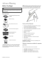 7
7
-
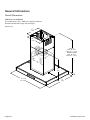 8
8
-
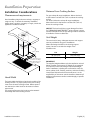 9
9
-
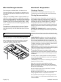 10
10
-
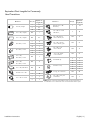 11
11
-
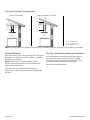 12
12
-
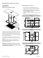 13
13
-
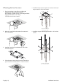 14
14
-
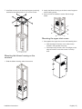 15
15
-
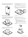 16
16
-
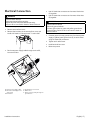 17
17
-
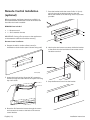 18
18
-
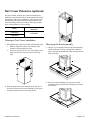 19
19
-
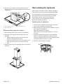 20
20
-
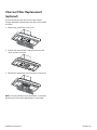 21
21
-
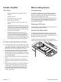 22
22
-
 23
23
-
 24
24
-
 25
25
-
 26
26
-
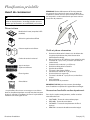 27
27
-
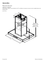 28
28
-
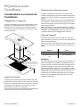 29
29
-
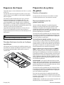 30
30
-
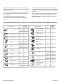 31
31
-
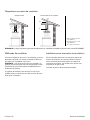 32
32
-
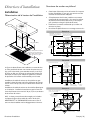 33
33
-
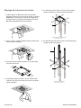 34
34
-
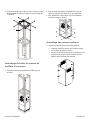 35
35
-
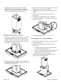 36
36
-
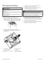 37
37
-
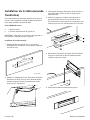 38
38
-
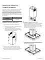 39
39
-
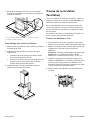 40
40
-
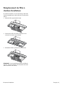 41
41
-
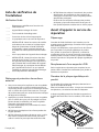 42
42
-
 43
43
-
 44
44
-
 45
45
-
 46
46
-
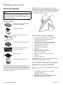 47
47
-
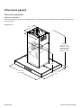 48
48
-
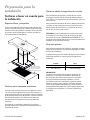 49
49
-
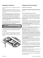 50
50
-
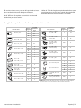 51
51
-
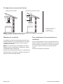 52
52
-
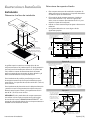 53
53
-
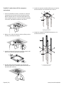 54
54
-
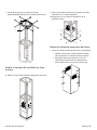 55
55
-
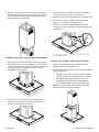 56
56
-
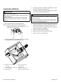 57
57
-
 58
58
-
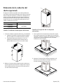 59
59
-
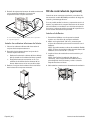 60
60
-
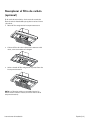 61
61
-
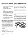 62
62
-
 63
63
-
 64
64


en otros idiomas
- français: Thermador HMIB42WS Guide d'installation
- English: Thermador HMIB42WS Installation guide
Artículos relacionados
-
Thermador HDDB36WS Guía de instalación
-
Thermador CHXTHMIB Guía de instalación
-
-
Thermador HMDW30WS Guía de instalación
-
-
Thermador HMWB30WS Guía de instalación
-
Thermador HMDW36WS Guía de instalación
-
Thermador RECHMIB Guía de instalación
-
-
Thermador HMCB36WS Guía de instalación
