
1
R. 06/23 836 867
SAMOA Industrial, S.A. · Pol. Ind. Porceyo, I-14 · Camino del Fontán, 831 · 33392 - Gijón - Spain · Tel.: +34 985 381 488 · www.samoaindustrial.com
2023_06_22-17:30
Part No. / Cód. / Кодировка:
365 811
365 812
365 813
Parts and technical service guide
Guía de servicio técnico y recambio
Руководство по эксплуатации и обслуживанию
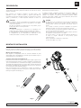
PRESET MECHANICAL METER MP30 2
PISTOLA MECÁNICA DE PRESELECCIÓN MP30 7
ПРЕДУСТАНОВЛЕННЫЙ МЕХАНИЧЕСКИЙ СЧЕТЧИК MP30 12
EN
ES
RU

2836 867 R. 06/23
SAMOA Industrial, S.A. · Pol. Ind. Porceyo, I-14 · Camino del Fontán, 831 · 33392 - Gijón - Spain · Tel.: +34 985 381 488 · www.samoaindustrial.com
2023_06_22-17:30
EN
Preset mechanical meters, with volumetric rotatory piston. MP30 have been
specifically designed to measure and dispense volumes of all kinds of synthetic
and mineral oils.
Graduated in “liters”, “quarts/gallons” or “gallons”, it is suitable to fill engines,
gear boxes and transmissions; or dispense lubricants in fleet service shops, off-
road vehicles, mining or marine equipment maintenance facilities.
DESCRIPTION
ASSEMBLY AND INSTALLATION
The line of preset mechanical meter is especially designed to support a severed
use and extreme environmental conditions. A robust integral polycarbonate
based housing guarantees maximum strength against drops and impacts. No
calibration required, high-accuracy to a large viscosity range.
CAUTION
Always read and follow the fluid manufacturer’s recommendations
regarding the use of protective eye wear, clothing, gloves, and other
personal protective equipment.
Do not alter or modify any parts of this product; doing so may cause
damage and/or personal injury.
IMPORTANT
Read these safety warnings and instructions in this manual completely,
before installation and start up of the meter.
It is the responsibility of the purchaser to retain this manual
for reference.
Failure to comply with the recommendations stated in this manual
will damage the meter and void factory warranty.
DANGER
Not for use with fluids that have a flash point below 38 ºC (100 ºF),
for example: gasoline or alcohol. Sparking could result in an explosion
which could result in death.
Use the equipment with fluids which are compatible with the wetted
parts of the equipment. See the relevant section of technical
specifications.
Do not exceed the maximum working pressure or temperature. See
the relevant section of technical specifications.
Release all pressure in the system before performing any installation
or maintenance on the equipment.
Do not place your hand or fingers over the dispensing nozzle and/or
aim the nozzle at a person at any time. Personal injury may result.
Airborne particles and loud noise hazards.
Use ear and eye protection.
! !
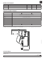
To use the preset mechanical meter only it’s necessary put the nozzle and
connect the control valve to the fluid hose.
Nozzle assembly (1)
To ensure sealing, screw the nozzle using the provided o-ring or bonded seal
in correct place.
Control valve connection to the fluid hose (2)
Attach the swivel cover to the hose before installing the oil gun in the system.
The swivel cover is compatible with 1/2" hoses, either with male fixed
terminal or swivel nut (Fig. 1). Deppending on the terminal type hose may
be necessary open the end of the swivel cover to place through the hose. The
swivel cover includes a slot in it for easy opening (Fig. 2)
To connect the gun to piping system, fix the gun body. Rotate the free end
of the swivel until desired torque (Fig. 3).
Fig. 1
Fig. 2
Fig. 3
1
2

3
R. 06/23 836 867
SAMOA Industrial, S.A. · Pol. Ind. Porceyo, I-14 · Camino del Fontán, 831 · 33392 - Gijón - Spain · Tel.: +34 985 381 488 · www.samoaindustrial.com
2023_06_22-17:30
OPERATION
Oil continuously passes through the metering chamber when the trigger is
pressed. The piston rotates in the metering chamber by the flow pressure. Each
oscillation of the piston equates to a given amount of fluid and makes the
output shaft rotate through the gear train.
The output shaft moves the pointer knob clockwise around the dial toward
zero, unlocking the trigger and automatically stopping the supply.
There is also a non resettable 5-digit totalizer fixed to the output shaft.
STOP MANUAL SUPPLY
ZERO ADJUST
WARNING
Always turn pointer knob counter-clockwise.
Do not turn clockwise, severe internal damage will occur
to mechanism.
!
Perform the following procedure to start working with the preset
mechanical meter:
1. Install the preset mechanical meter in the supply line (see to previous
point “Mounting and installation section”).
2. Turn the pointer knob to a non-zero amount, always rotate in the
direction indicated by the arrows of the dial (counter-clockwise). If the
pointer knob does not rotate smoothly do not force it, inspect the meter
for anomalies.
3. Open the nozzle by pulling the end.
4. To dispense oil, press the trigger until it locks. The fluid should begin to exit
the nozzle once the air trapped in the supply line is removed.
5. Check the pointer knob rotates (clockwise) around the graduated dial,
discounting the amount dispensed.
6. Check that the pointer knob stops at zero, adjust if necessary (see “zero
adjust“ section).
7. Close the nozzle by pushing the end.
8. Look for leaks when meter is at rest.
9. Preset mechanical meter is ready to use.
2
3
4
To stop dispensing before reaching the pre-set volume, push down the lock
(see figure).
Use a Phillips head screwdriver with a 4 mm diameter or less.
Insert the screwdriver into the slot until the phillips head screw. Turn the
screw clockwise if the pointer knob stops before zero and counterclockwise
otherwise.

4836 867 R. 06/23
SAMOA Industrial, S.A. · Pol. Ind. Porceyo, I-14 · Camino del Fontán, 831 · 33392 - Gijón - Spain · Tel.: +34 985 381 488 · www.samoaindustrial.com
2023_06_22-17:30
EN
1
4
3
2
OPERATION
PRESSURE RELIEF PROCEDURE
The equipment stays under pressure until manually released. To reduce the
risk of serious injury from pressurized fluid, accidental spray from the
dispenser or splashing fluid, release all pressure using the “Pressure relief
procedure” before any servicing.
Pressure relief procedure
1. Turn off the power supply to the pump.
2. Open system drain valve to release pressure.
3. Leave the drain valve open until you have completed repairs and you are
ready to pressurize the system.
WARNING
Make sure there is no pressure in the system and the pump is
disconnected before performing maintenance or cleaning.
!
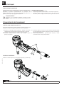
MAINTENANCE
STRAINER CLEANING OR REPLACING
VALVE DISASSEMBLY
Preset control meter is provided with a strainer. To inspect or replace follow
the instructions below:
1. Follow “Pressure relief procedure” before removing the preset control
meter from installation.
2. Remove the cover (1) of the swivel and loosen the nut (2) of the hose.
3. Remove the o-ring (3) that secure the filter (4) and the filter.
4. Check the filter, clean it with mineral spirits or replace as necessary, (be
careful, do not damage the strainer elements).
5. Reassemble again the filter with the o-ring and then install the hose with
the swivel cover.
Loosen and remove the swivel (1), then remove the spring (2) and the valve (3).
1
3
2

5
R. 06/23 836 867
SAMOA Industrial, S.A. · Pol. Ind. Porceyo, I-14 · Camino del Fontán, 831 · 33392 - Gijón - Spain · Tel.: +34 985 381 488 · www.samoaindustrial.com
2023_06_22-17:30
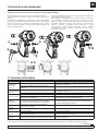
MAINTENANCE
REPLACING CAM ASSEMBLY O-RING
Disassemble valve first as described in the previous section.
Then unscrew the screws of the lock pawl (4) and the cam (5) to remove the
trigger (6).
To avoid damaging the o-rings, push out the cam (7) on one side until only the
o-ring of that side (8) is visible. Remove the o-ring and then fully remove the cam
with the other o-ring (9) on the opposite site.
To assembly, proceed the other way around taking care with the o-ring
of the cam.
To avoid damage to the o-rings in the cam assembly, it must be mounted a
single ring (9) on cam (7) and then place the cam in the gun by the end
without o-ring. Push gently the cam until the end without o-ring appears on
the side of the gun, with special care that only the groove of the o-ring poke
out. Introduce the o-ring (8) and place the shaft in position.
557
8
4
679
79
8
7
Problem Cause Solution
No fluid passing
through the meter.
Blocked strainer. Remove the strainer and clean any dirt particles.
Replace if necessary.
Dirt particles jamming the wetted parts rotors. Dismantle wetted parts of the meter assembly and clean.
Low flow rate. Blocked strainer. Remove the strainer and clean any dirt particles.
Replace if necessary.
Low oil supply pressure Increase oil supply pressure.
Low accuracy Dirt in chamber. Dismantle metering chamber assembly and clean.
Any parts of metering chamber are worn or damaged. (*) Replace the complete metering chamber assembly.
Valve will not close Foreign material on valve seal. Valve seal worn or damaged. Disassembly the valve for inspection.
If it is not damaged clean seat valve, otherwise replace the valve.
Leaking at nozzle Nozzle is open. O-rings worn or damaged. Manually close the nozzle. Replace nozzle.
Leakage at cam O-rings worn or damaged. Replace o-rings.
Leakage at swivel The swivel is loose. Tighten swivel assembly.
Swivel o-ring worn or damaged. Replace o-ring.
Packing gland leak. O-rings worn or damaged. (*) Replace packing gland kit.
(*) To replace the complete metering chamber assembly and packing gland kit contact tech support.
TROUBLESHOOTING

6836 867 R. 06/23
SAMOA Industrial, S.A. · Pol. Ind. Porceyo, I-14 · Camino del Fontán, 831 · 33392 - Gijón - Spain · Tel.: +34 985 381 488 · www.samoaindustrial.com
2023_06_22-17:30
EN
AVAILABLE MODELS
TECHNICAL SPECIFICATIONS
Part Number Description Dial Totalizer Connection
365811 Preset mechanical meter MP30 – Liters 0 - 60 Liters Liters
Litros ½" BSP - ½" NPT
365812 Preset mechanical meter MP30 – Quarts 0 - 60 Quarts Gallons ½" BSP - ½" NPT
365813 Preset mechanical meter MP30 - Gallons 0 - 60 Gallons Gallons ½" BSP - ½" NPT
Model Liters Quarts Gallons
Flow range 1 - 30 l/min (0,25 - 8 gpm) (*)
(deppending of the viscosity of the fluid and temperature)
Max. working pressure 100 bar (1.450 psi)
Operating temperature -45 ºC to 70 ºC (-50 ºF to 160 ºF)
Accuracy ±0,65% (**)
Dial Resolution 0,25 x unit of measure
Fluid viscosity range 50 - 50.000 cSt
Inlet connection 1/2" BSP / 1/2" NPT
Compatible fluids Low to high viscosity lubricants, ATF and Antifreeze
Wetted materials Aluminum, stainless steel, zinc alloy, NBR, zinc plated steel, brass
Totalizing register 5 digits (99.999 liters) 5 digits (99.999 Gallons) 5 digits (99.999 gallons)
Weight 2 kg (4,4 lbs)
(*) Tested with SAE 30 oil. Minimum-maximum flow rates will vary with fluid viscosity.
(**) Working with high or low viscosity fluids, as well as very high o very low flow rates (less than 3 l/min, 0,8 gpm), may be less accurate.
PARTS LIST
PAGES 17-19.
265 (10,4"
)
136 (5,4")
184 (7,2") 99 (3,9")
351 (13,8")
282 (11,1")
129 (5,1")

7
R. 06/23 836 867
SAMOA Industrial, S.A. · Pol. Ind. Porceyo, I-14 · Camino del Fontán, 831 · 33392 - Gijón - Spain · Tel.: +34 985 381 488 · www.samoaindustrial.com
2023_06_22-17:30
ES
DESCRIPCIÓN
Las pistolas contadoras mecánicas de preselección MP30 han sido diseñadas
específicamente para medir y dispensar volúmenes de toda clase de aceites
sintéticos y minerales.
Estos contadores son medidores volumétricos de pistón rotativo, están
graduados en “litros”, “cuartos de galón” y “galones” para cubrir las
necesidades de las líneas de producción cuando se rellenan motores, cajas de
cambio y transmisiones; o cuando dispensan lubricante en talleres de
MONTAJE E INSTALACIÓN
mantenimiento de flotas, vehículos todo terreno, minería o instalaciones de
mantenimiento de equipos marinos.
La gama de pistolas contadoras mecánicas de preselección MP30 son
especialmente adecuadas para trabajos duros y condiciones industriales
extremas. Son robustos, la carcasa de policarbonato garantiza máxima
resistencia contra caídas e impactos. No requieren calibración, alta precisión
para una amplia gama de de viscosidades.
ATENCIÓN
Lea siempre y siga las recomendaciones del fabricante del fluido
relativas al uso de gafas de protección, ropa, guantes y otros equipos
de protección personal.
No altere ni modifique los componentes de este producto ya que
podría causar daños o lesiones personales.
IMPORTANTE
Lea todas las advertencias e instrucciones de seguridad de este
manual antes de la instalación y puesta en marcha del contador.
Es responsabilidad del comprador guardar este manual de referencia.
El incumplimiento de las recomendaciones establecidas en este
manual puede dañar el contador y anula la garantía de fábrica.
PELIGRO
No apto para el uso con fluidos que tienen un punto de inflamación
por debajo de 38 ºC (100 ºF), por ejemplo: gasolina o alcohol. Las
chispas podrían ocasionar una explosión que podrían causar la
muerte.
Use el equipo con fluidos y soluciones compatibles con las partes
húmedas del equipo. Ver sección de especificaciones técnicas.
No exceda la presión ni temperatura máximas de trabajo del equipo.
Ver sección de especificaciones técnicas.
Libere toda presión en el sistema antes de realizar cualquier operación
de instalación o mantenimiento en el equipo.
No coloque la mano o los dedos sobre la boquilla de distribución ni
la dirija en ningún momento a una persona, puede
ocasionar lesiones.
Riesgo de partículas en suspensión y ruidos altos.
Use protección para ojos y oídos.
! !
Para usar la pistola contadora de preselección sólo es necesario montar la
extensión y hacer la conexión de la pistola a la manguera de la línea de fluido.
Montaje de la extensión (1)
Para asegurar la estanqueidad, monte la extensión utilizando la junta
suministrada (tórica o metaloplástica) y teniendo especial cuidado de que la
junta permanezca en su alojamiento.
Conexión de la pistola a la manguera (2)
Previamente a la conexión de la pistola a la red, debe acoplar el protector de
rótula a la manguera. Este protector de rótula es compatible con mangueras de
1/2” con terminal macho fijo o terminal tuerca loca (Fig. 1). En función del tipo
de terminal de la manguera puede ser necesario abrir el extremo del protector
para permitir su deslizamiento por la manguera. El protector posee una ranura
en su extremo que facilita su apertura (Fig. 2).
Para conectar la pistola a la red, mantenga fijo el cuerpo de la pistola y el
extremo de la manguera mientras se hace girar el extremo libre de la rótula
hasta lograr el apriete deseado (Fig. 3).
Fig. 1
Fig. 2
Fig. 3
1
2

8836 867 R. 06/23
SAMOA Industrial, S.A. · Pol. Ind. Porceyo, I-14 · Camino del Fontán, 831 · 33392 - Gijón - Spain · Tel.: +34 985 381 488 · www.samoaindustrial.com
2023_06_22-17:30
ES
OPERACIÓN
Cuando se presiona el gatillo el aceite pasa continuamente a través de la
cámara de medición por el puerto de entrada y sale por el puerto de salida, la
presión del fluido hace girar el pistón dentro de la cámara. Cada oscilación del
pistón equivale a una cantidad de fluido dada y hace girar el eje de salida a
través de un tren de engranajes.
El eje de salida mueve una aguja alrededor del dial en sentido horario hasta
llegar a cero, entonces acciona la leva que bloquea el gatillo y detiene
automáticamente el suministro. También hay un totalizador de 5 dígitos no
reseteable fijo al eje de salida.
PARADA MANUAL DEL SUMINISTRO
AJUSTAR LA AGUJA A CERO
ADVERTENCIA
Gire la aguja siempre en sentido anti-horario.
Nunca la gire en sentido horario, puede causar daños
internos al mecanismo.
!
Realice el siguiente procedimiento para poner en funcionamiento
la pistola contadora de preselección:
1. Monte la pistola contadora de preselección en la línea de suministro
(Según el apartado 3. “Montaje e instalación”).
2. Gire la aguja hasta una cantidad distinta de cero (1), siempre en la
dirección que indican las flechas del dial (sentido contrario a las agujas
del reloj). Si la aguja no gira fácilmente no la fuerce, inspeccione el
contador en busca de anomalías.
3. Abra la boquilla tirando del extremo (2).
4. Para suministrar aceite presionar el gatillo hasta que quede bloqueado
(3), el fluido debe comenzar a salir por la boquilla una vez que el aire
atrapado en la red sea eliminado.
5. Compruebe que la aguja gira alrededor del dial graduado (en sentido
horario) descontando la cantidad dispensada.
6. Compruebe que la aguja se detiene en cero. (Ajuste si es necesario según
se indica en el apartado “Ajustar la aguja a cero“).
7. Cierre la boquilla empujado el extremo.
8. Verifique la ausencia de fugas con el contador en reposo.
9. El contador está listo para ser usado.
2
3
4
Para detener el suministro antes de llegar a completarlo hay que empujar
hacia abajo sobre el bloqueo (ver figura).
Utilice un destornillador con punta en cruz (cabeza Phillips) de un diámetro
inferior a 4 mm.
Introduzca el destornillador por la ranura de la leva hasta llegar al tornillo de
cabeza en cruz sobre el que empuja la leva. Gire este tornillo en sentido
horario si la aguja se detiene antes de cero y al revés en caso contrario.

9
R. 06/23 836 867
SAMOA Industrial, S.A. · Pol. Ind. Porceyo, I-14 · Camino del Fontán, 831 · 33392 - Gijón - Spain · Tel.: +34 985 381 488 · www.samoaindustrial.com
2023_06_22-17:30
ES
OPERACIÓN
1
4
3
2
PROCEDIMIENTO PARA LIBERAR PRESIÓN
El equipo permanece presurizado hasta que se libere la presión manualmente.
Para reducir el riesgo de lesiones graves por fluido presurizado, pulverización
accidental del dispensador o salpicaduras de fluido siga siempre el
“procedimiento para liberar presión” antes de realizar operaciones
de limpieza o mantenimiento.
Procedimiento para liberar presión
1. Cierre la alimentación de la bomba.
2. Abra las válvulas del circuito para liberar presión.
3. Deje las válvulas abiertas hasta que haya completado la reparación y esté
listo para presurizar el sistema.
ADVERTENCIA
Asegúrese que no hay presión en el circuito y que la bomba se
encuentra desconectada antes de realizar operaciones de
mantenimiento o limpieza.
!
MANTENIMIENTO
LIMPIEZA O SUSTITUCIÓN DEL FILTRO
DESMONTAJE DE LA VÁLVULA DE LA PISTOLA
La pistola contadora de preselección está provista de un filtro. Para revisar su
estado o realizar su sustitución siga las siguientes instrucciones:
1. Realice el “Procedimiento para liberar la presión” antes de retirar la
pistola contadora de preselección de la instalación.
2. Retire el protector de la rótula (1) en caso de estar montado y afloje la
tuerca (2) de la manguera.
3. Extraiga la junta tórica (3) que fija el filtro (4) y a continuación el filtro.
4. Revise el filtro y proceda a su limpieza con disolvente o sustitución en
caso necesario, (tener cuidado de no dañar el filtro).
5. Vuelva a montar de nuevo el filtro con la junta tórica y a continuación la
manguera con el protector de rótula.
Afloje y retire la rótula (1) para extraer el muelle (2) y la válvula-empujador (3).
1
3
2

10 836 867 R. 06/23
SAMOA Industrial, S.A. · Pol. Ind. Porceyo, I-14 · Camino del Fontán, 831 · 33392 - Gijón - Spain · Tel.: +34 985 381 488 · www.samoaindustrial.com
2023_06_22-17:30
ES
MANTENIMIENTO
SUSTITUCIÓN DE LA TÓRICA DEL EJE DE GIRO DE LA PISTOLA
Proceda en primer lugar al desmontaje de la válvula según lo descrito en el
apartado anterior.
A continuación quite los tornillos del trinquete de bloqueo (4) y del eje de
giro (5) para desmontar el gatillo (6).
Para no dañar las juntas tóricas, saque por un extremo el eje de giro (7) hasta
que asome sólo la junta de ese lado (8). Extraiga la tórica y a continuación
saque totalmente el eje con la otra junta (9) por el lado contrario.
Para realizar el montaje proceda de manera inversa poniendo especial
atención en el montaje de las juntas tóricas del eje de giro.
Para evitar dañar las juntas en el montaje del eje debe montar una sola tórica
(9) en el eje (7) e introducirlo en la pistola por el extremo sin junta. Deslice
el eje hasta que el extremo sin junta asome por el otro lateral de la pistola,
con especial cuidado de que sólo sobresalga la cajera de la junta. Introduzca
la junta (8) y coloque el eje en su posición.
557
8
4
679
79
8
7
(*) Para reemplazar el conjunto cámara de medición y el kit tuerca prensa estopa ponerse en contacto con el servicio técnico.
SOLUCIÓN DE PROBLEMAS
Síntoma Posible causa Solución
No pasa fluido
a través del contador.
Filtro obstruido. Desmonte el filtro y limpie cualquier partícula de suciedad.
Reemplace el filtro si es necesario.
Partículas de suciedad interfiriendo las piezas húmedas
del mecanismo. Desmonte las piezas húmedas del contador y límpielas.
Caudal bajo. Filtro obstruido. Desmonte el filtro y limpie cualquier partícula de suciedad.
Reemplace el filtro si es necesario.
Baja presión de aceite en la línea. Aumente la presión en la línea.
Poca precisión. Suciedad en la cámara de medición. Desmonte la cámara de medición y límpiela.
La cámara de medición está desgastada o dañada. (*) Reemplace el conjunto cámara de medición.
No se corta el suministro. Impurezas en el asiento de la válvula de la pistola.
Válvula de la pistola deteriorada.
Inspeccione la válvula, si no presenta daños limpie el asiento.
En caso contrario sustitúyala.
Fuga por la boquilla. La boquilla no está cerrada. Juntas tóricas dañadas. La boquilla se debe cerrar manualmente.
reemplace la extensión.
Fuga de aceite por el eje del gatillo. Juntas tóricas deterioradas. Sustituya las juntas tóricas.
Fuga de aceite por la rótula. La rótula no está bien apretada. Reapriete la tuerca de unión con la manguera.
Junta tórica de la rótula dañada. Sustituya la junta tórica.
Fugas por la tuerca prensa estopa. Juntas tóricas dañadas. (*) Reemplace el kit tuerca prensa estopa.

11
R. 06/23 836 867
SAMOA Industrial, S.A. · Pol. Ind. Porceyo, I-14 · Camino del Fontán, 831 · 33392 - Gijón - Spain · Tel.: +34 985 381 488 · www.samoaindustrial.com
2023_06_22-17:30
ES
MODELOS DISPONIBLES
ESPECIFICACIONES TÉCNICAS
Código Descripción Dial Totalizador Conexión
365811 Pistola contadora mecánica de Preselección MP30 - Litros 0 - 60 Litros Litros ½" BSP / ½" NPT
365812 Pistola contadora mecánica de Preselección MP30 - Cuartos de Galón 0 - 60 Cuartos Galones ½" BSP / ½" NPT
365813 Pistola Contadora mecánica de Preselección MP30 - Galones 0 - 60 Galones Galones ½" BSP / ½" NPT
Modelo Litros Cuartos Galones
Rango de Caudal 1 - 30 l/min (0,25 - 8 gpm) (*)
(dependiendo de la viscosidad del fluido y la temperatura)
Presión máxima de trabajo 100 bar (1.450 psi)
Rango de temperatura de funcio-
namiento -45 ºC a 70 ºC (-50 ºF a 160 ºF)
Precisión ±0,65% (**)
Resolución del dial 0,25 de la unidad de medida
Rango de viscosidad del fluido 50 - 50.000 cSt
Conexión de entrada 1/2" BSP / 1/2" NPT
Fluidos compatibles Lubricantes de baja y alta viscosidad, ATF y Anticongelante
Materiales partes húmedas Aluminio, Acero inoxidable, Aleación de Zinc, NBR, acero cincado, latón
Totalizador 5 dígitos (99.999 litros) 5 dígitos (99.999 galones) 5 dígitos (99.999 galones)
Peso 2 kg (4,4 lbs)
(*) Testado con aceite SAE 30. El rango de caudal varía con la viscosidad del fluido.
(**) Trabajar con fluidos de muy alta o baja viscosidad, así como caudales muy altos o bajos (inferiores a 3 l/min, 0,8 gpm) puede causar menor precisión.
LISTA DE PIEZAS
PÁGINAS 17-19.
265 (10,4"
)
136 (5,4")
184 (7,2") 99 (3,9")
351 (13,8")
282 (11,1")
129 (5,1")

12 836 867 R. 06/23
SAMOA Industrial, S.A. · Pol. Ind. Porceyo, I-14 · Camino del Fontán, 831 · 33392 - Gijón - Spain · Tel.: +34 985 381 488 · www.samoaindustrial.com
2023_06_22-17:30
RU
Предустановленные механические счетчики, с объемным роторным
поршнем. MP30 были специально разработаны для измерения и
дозирования объемов всех видов синтетических и минеральных масел.
Градуированный в «литрах», «квартах/галлонах» или «галлонах», он
подходит для заправки двигателей, коробок передач и трансмиссий;
или распределять смазочные материалы в мастерских автопарка,
внедорожниках, на предприятиях по обслуживанию горнодобывающего
или морского оборудования.
ОПИСАНИЕ
МОНТАЖ И УСТАНОВКА
Линия предустановленных механических счетчиков специально
разработана для работы в тяжелых и в экстремальных условиях
окружающей среды. Прочный цельный корпус на основе поликарбоната
гарантирует максимальную защиту от падений и ударов. Калибровка
не требуется, высокая точность при широком диапазоне вязкости.
ВНИМАНИЕ!
Всегда читайте и выполняйте рекомендации производителя
жидкости относительно использования защитных очков,
одежды, перчаток и других средств индивидуальной защиты.
Не изменяйте и не модифицируйте какие-либо части этого
продукта; это может привести к повреждению и / или травме.
ВАЖНО!
Перед установкой и запуском счетчика полностью прочтите эти
предупреждения и инструкции по технике безопасности
данного руководства.
Покупатель несет ответственность за сохранение данного
руководства в качестве справочной информации. .
Несоблюдение рекомендаций, изложенных в данном
руководстве, может привести к повреждению прибора и
повлечь недействительность заводской гарантии.
ПРЕДОСТЕРЕЖЕНИЕ!
ОПАСНО! Не использовать с жидкостями, температура
воспламенения которых ниже 38 ºC (100 ºF), например, бензин
или спирт. Возникновение искры может привести к взрыву,
который может привести к смерти.
Используйте оборудование с жидкостями, совместимыми со
смачиваемыми частями оборудования. Смотрите
соответствующий раздел технических характеристик.
Не превышайте максимальное рабочее давление или
температуру. Смотрите соответствующий раздел технических
характеристик.
Выпустите все давление в системе перед выполнением любой
установки или обслуживания оборудования.
Никогда не кладите руки или пальцы на дозирующую насадку и/или
не направляйте насадку на людей. Это может привести к травмам.
Опасность из-за переносимых по воздуху частиц и
сильного шума.
Используйте средства защиты ушей и глаз.
! !
Чтобы использовать только предварительно настроенный механический
счетчик, необходимо установить сопло и подсоединить регулирующий
клапан к шлангу для жидкости.
Монтаж форсунки
Для обеспечения герметичности вверните форсунку с помощью
прилагаемого уплотнительного кольца или клеевого уплотнения в
соответствующее место.
Подключение регулирующего клапана к шлангу для жидкости (2)
Прикрепите поворотную крышку к шлангу перед установкой масляного
пистолета в систему. Поворотная крышка совместима со шлангами 1/2
«либо с фиксированным штекером, либо с накидной гайкой (рис. 1). В
зависимости от типа клеммы может потребоваться открыть конец
поворотной крышки, чтобы пропустить через шланг. крышка имеет
прорезь для легкого открывания (рис.2)
Чтобы подсоединить пистолет к системе трубопроводов, закрепите
корпус пистолета. Поверните свободный конец вертлюга до желаемого
момента (рис. 3).
рис. 1
рис. 2
рис. 3
1
2

13
R. 06/23 836 867
SAMOA Industrial, S.A. · Pol. Ind. Porceyo, I-14 · Camino del Fontán, 831 · 33392 - Gijón - Spain · Tel.: +34 985 381 488 · www.samoaindustrial.com
2023_06_22-17:30
RU
ЭКСПЛУАТАЦИЯ
Выходной вал перемещает ручку указателя по часовой стрелке вокруг
шкалы в сторону нуля, разблокируя спусковой крючок и автоматически
останавливая подачу.
Выходной вал перемещает ручку указателя по часовой стрелке вокруг
шкалы в сторону нуля, разблокируя спусковой крючок и автоматически
останавливая подачу.
Существует еще и несбрасываемый 5-значный сумматор прикрепленный
к выходному валу.
ОСТАНОВИТЬ РУЧНУЮ ПОДАЧУ
РЕГУЛИРОВКА НУЛЯ
ПРЕДОСТЕРЕЖЕНИЕ
Всегда поворачивайте ручку указателя против часовой стрелки.
Не поворачивайте по часовой стрелке, это может серьезно
повредить механизм.
!
Выполните следующую процедуру, чтобы начать работу с
предварительно настроенным механическим счетчиком:
1. Установите предварительно настроенный механический счетчик в
линию подачи (см. Пункт 3. «Монтаж и установка»).
2. Поверните ручку указателя на ненулевое значение, всегда
вращайте в направлении, указанном стрелками на шкале (против
часовой стрелки). Если ручка указателя не вращается плавно, не
применяйте силу, проверьте измеритель на наличие аномалий.
3. Откройте сопло, потянув за конец.
4. Чтобы залить масло, нажмите спусковой крючок до его фиксации.
Жидкость должна начать выходить из сопла после того, как будет
удален воздух, застрявший в линии подачи.
5. Убедитесь, что ручка указателя вращается (по часовой стрелке)
вокруг шкалы с градуировкой без учета выданного количества.
6. Убедитесь, что ручка указателя останавливается на нуле, при
необходимости отрегулируйте (см. Раздел «Настройка нуля»).
7. Закройте сопло, надавив на конец.
8. Посмотрите нет ли утечек, когда счетчик находится в
состоянии покоя.
9. Предустановленный механический счетчик готов к использованию.
2
3
4
To Чтобы остановить дозирование до достижения предварительно
установленного объема, нажмите фиксатор (см. Рисунок).
Используйте отвертку Phillips с диаметром 4 мм или менее. Вставьте
отвертку в прорезь до винта с крестообразной головкой. Поверните
винт по часовой стрелке, если ручка указателя остановится до нуля, и
против часовой стрелки в противном случае.

14 836 867 R. 06/23
SAMOA Industrial, S.A. · Pol. Ind. Porceyo, I-14 · Camino del Fontán, 831 · 33392 - Gijón - Spain · Tel.: +34 985 381 488 · www.samoaindustrial.com
2023_06_22-17:30
RU
ЭКСПЛУАТАЦИЯ
УМЕНЬШЕНИЕ ДАВЛЕНИЯ
Оборудование остается под давлением, пока не будет разблокировано
вручную. Чтобы снизить риск серьезных травм из-за жидкости под
давлением, случайного разбрызгивания из дозатора или
разбрызгивания жидкости, перед любым обслуживанием сбросьте все
давление, используя «Процедуру сброса давления».
ПРЕДОСТЕРЕЖЕНИЕ
Убедитесь, что нет никакого давления в системе и насос
отключен перед выполнением технического обслуживания или
чистки.
!
ТЕХНИЧЕСКОЕ ОБСЛУЖИВАНИЕ
ЧИСТКА ИЛИ ЗАМЕНА ФИЛЬТРА
РАЗБОРКА КЛАПАНА
Контрольно-измерительный прибор снабжен сетчатым фильтром. Для
проверки или замены следуйте приведенным ниже инструкциям:
1. Выполните «Процедуру сброса давления», прежде чем снимать
предварительно настроенный контрольный прибор с установки.
2. Снимите крышку (1) вертлюга и ослабьте гайку (2) шланга.
3. Снимите уплотнительное кольцо (3), которое крепит
фильтр (4) и фильтр.
4. Проверьте фильтр, очистите его уайт-спиритом (растворителем)
или при необходимости замените (будьте осторожны, не повредите
фильтрующие элементы).
5. Снова соберите фильтр с уплотнительным кольцом, а затем
установите шланг с поворотной крышкой.
Ослабьте и снимите вертлюг (1), затем снимите пружину (2) и клапан (3).
1
3
2
Процедура сброса давления
1. Выключите электропитание насоса.
2. Откройте дренажный клапан системы, чтобы сбросить давление.
3. Оставьте сливной клапан открытым до тех пор, пока вы не
закончите ремонт и не будете готовы повысить давление в системе.
1
4
3
2

15
R. 06/23 836 867
SAMOA Industrial, S.A. · Pol. Ind. Porceyo, I-14 · Camino del Fontán, 831 · 33392 - Gijón - Spain · Tel.: +34 985 381 488 · www.samoaindustrial.com
2023_06_22-17:30
RU
ТЕХНИЧЕСКОЕ ОБСЛУЖИВАНИЕ
ЗАМЕНА УПЛОТНИТЕЛЬНОГО КОЛЬЦА КУЛАЧКОВОЙ ШАЙБЫ
Сначала разберите клапан, как описано в предыдущем разделе.
Затем отверните винты защелки замка (4) и кулачка (5), чтобы удалить
спуск (6).
Во избежание повреждения уплотнительных колец, выталкивайте
кулачок (7) с одной стороны, пока не будет видно только уплотнительное
кольцо с этой стороны (8). Снимите уплотнительное кольцо, а затем
полностью снимите кулачок с другим уплотнительным кольцом (9) на
противоположной стороне.
При сборке действуйте в обратном порядке, обращая внимание на
уплотнительное кольцо кулачка.
Чтобы избежать повреждения уплотнительных колец в кулачковом
узле, необходимо установить одно кольцо (9) на кулачок (7), а затем
поместить кулачок в пистолет до конца без уплотнительного кольца.
Осторожно надавите на кулачок, пока конец без уплотнительного
кольца не появится на боковой стороне пистолета, с особой
осторожностью, чтобы наружу выступала только канавка
уплотнительного кольца. Вставьте уплотнительное кольцо (8) и
установите вал на место.
557
8
4
679
79
8
7
Проблема Причина Решение
Через
измеритель
не проходит
жидкость.
Заблокирован сетчатый фильтр. Снимите сетчатый фильтр и удалите все частицы грязи. При
необходимости замените.
Частицы грязи забивают роторы смачиваемых
деталей. Снимите смачиваемые части счетчика в сборе и очистите.
Низкая
скорость подачи
жидкости.
Заблокирован сетчатый фильтр. Снимите сетчатый фильтр и удалите все частицы грязи. При
необходимости замените.
Низкое давление подачи масла. Увеличьте давление подачи масла.
Низкая точность.
Грязь в камере. Демонтировать узел дозирующей камеры и очистить.
Какие-либо части дозирующей камеры могут быть
изношены или повреждены. (*) Замените весь узел дозирующей камеры.
Клапан не
закрывается.
Посторонний материал на уплотнении клапана.
Уплотнение клапана изношено или повреждено.
Разберите клапан для проверки.
Если он не поврежден, очистите клапанный пневмоаппарат, в
противном случае замените клапан.
Утечка из сопла. Сопло открыто. Изношены или повреждены
уплотнительные кольца. Закройте сопло вручную. Заменить сопло.
Утечка в
кулачке. Изношены или повреждены уплотнительные кольца. Замените уплотнительные кольца.
Утечка в
вертлюге.
Вертлюг ослаблен. Затяните узел вертлюга.
Изношено или повреждено поворотное
уплотнительное кольцо. Замените уплотнительное кольцо.
Утечка
сальника. Изношены или повреждены уплотнительные кольца. (*) Замените сальник.
(*) Для замены всего узла измерительной камеры и комплекта сальникового уплотнения обратитесь в службу технической поддержки.
УСТРАНЕНИЕ НЕПОЛАДОК

16 836 867 R. 06/23
SAMOA Industrial, S.A. · Pol. Ind. Porceyo, I-14 · Camino del Fontán, 831 · 33392 - Gijón - Spain · Tel.: +34 985 381 488 · www.samoaindustrial.com
2023_06_22-17:30
RU
ДОСТУПНЫ СЛЕДУЮЩИЕ МОДЕЛИ
ТЕХНИЧЕСКИЕ ХАРАКТЕРИСТИКИ
Номер Детали Описание Индикатор Тотализатор Подключение
365811 Предустановленный механический счетчик MP30 - Литры 0 - 60 Литры Литры ½" BSP / ½" NPT
365812 Предустановленный механический счетчик MP30 - Кварты 0 - 60 Кварты Кварты ½" BSP / ½" NPT
365813 Предустановленные механический счетчик MP30 - галлоны 0 - 60 Галлоны Галлоны ½" BSP / ½" NPT
Модель Литры Кварты Галлоны
Диапазон расхода 1 - 30 л / мин (0,25 - 8 галлонов в минуту) (*)
(в зависимости от вязкости жидкости и температуры)
Макс. рабочее давление 100 бар (1.450 psi)
Рабочая температура -45 ºC ~ 70 ºC (-50 ºF ~ 160 ºF)
Точность ±0,65% (**)
Разрешение циферблата 0,25 x единица измерения
Диапазон вязкости жидкости 50 - 50.000 cSt
Входное соединение 1/2" BSP / 1/2" NPT
Совместимые жидкости Смазочные материалы с низкой и высокой вязкостью, ATF и антифризы
Смачиваемые материалы Алюминий, нержавеющая сталь, цинковый сплав, NBR, оцинкованная сталь, латунь
Тотализадор 5 цифр (99,999 литров) 5 цифр (99,999 галлонов) 5 цифр (99,999 галлонов)
Вес 2 кг (4,4 фунта)
(*)Протестировано на основе масла SAE 30. Минимальный-максимальный расход зависит от вязкости жидкости.
(**)Работа с жидкостями с высокой или низкой вязкостью, а также с очень высокой или очень низкой скоростью потока (менее 3 л / мин, 0,8
галлона в минуту) может быть менее точной.
РЕМОНТНЫЕ КОМПЛЕКТЫ
СТРАНИЦА 17-19.
265 (10,4"
)
136 (5,4")
184 (7,2") 99 (3,9")
351 (13,8")
282 (11,1")
129 (5,1")

17
R. 06/23 836 867
SAMOA Industrial, S.A. · Pol. Ind. Porceyo, I-14 · Camino del Fontán, 831 · 33392 - Gijón - Spain · Tel.: +34 985 381 488 · www.samoaindustrial.com
2023_06_22-17:30
PART LIST / LISTA DE RECAMBIOS / PIÈCES DE RECHANGE /
TEILELISTE / PEÇAS DE REPOSIÇÃO / ПЕРЕЧЕНЬ ДЕТАЛЕЙ
RUEN ES FR DE
PART LIST / LISTA DE RECAMBIOS / PIÈCES DE RECHANGE /
TEILELISTE / PEÇAS DE REPOSIÇÃO / ПЕРЕЧЕНЬ ДЕТАЛЕЙ
Kit Nº
369863
BSP
Part Nº
736121
Kit Nº
369862
Kit Nº
369856
For / para
365811
369857
Kit Nº
For / para
365812
Kit Nº
369858
For / para
365813
369855
Kit Nº
For / para
365813
369850
Kit Nº
369853
Kit Nº
For / para 365811
Kit Nº
369854
For / para 365812
Kit Nº
369852
For / para
365812
365813
369851
Kit Nº
For / para
365811
369802
Kit Nº
369860
Kit Nº
Kit Nº
369861
369817
Kit Nº
For / para
365812
365813
Kit Nº
369859
For / para
365811
896604
Part Nº
Part Nº
369244
946704
Part Nº
Part Nº
736820
5
6
7
2
3
4
28
27
26
25
24
23
22
21
20
17
18
19
16
9
10
11 29
30
12
13
14
15
31
33
32
14
34
35
37
38
39
40
18
41
36
43
44
47
36
42
8
1
45
46
Ctd.
Código
Code
Denominación
Denomination
Marca
Pos.
Observaciones
Observations
1
896440_01
Z14 - M0,55 - h5
104 Latón
1
896439_02
Z50 - M0,55 - h2,5
103 Latón
1
736635
Acondicionador pistola contadora MC30
102
Acondicionador
1
836921
Caja Pistola + contador PC-20 S/M
101
-/Material <sin especificar>
2
369244_5
Junta torica 16x1,8 NBR-75
100
Comercial
1
369244_6
Junta metaloplastica 1/2" Acero-NBR
99
Comercial
1
369244_4
Anillo elástico p/agujero 20mm DIN-7993 B
98
Comercial.
1
369244_3
Quad Ring 10,77x2,62 NBR-70
97
Comercial
1
369244_2
Cierre Boquilla preselección
96
1
896601_1
Tapa personalizable
95
-
1
896600_2
94
1
896605_2
Junta de válvula
93
-
1
836404_1
92
-
1
836484
Tope bolas
91
Redondo
4mm. Latón
20
944051
Bola Ac. (IV Cr) 1/8" (3.175mm)
90
Comercial
1
946092
Junta torica 16x2
89
NBR 75 Comercial
1
896602
Aro de apoyo pistola Ac. ND
88
16mm. PTFE
1
836483
Rosca hembra BSP rótula pistola ND
87
Exag. 28mm. e/c F-212
1
940705
Tornillo fijación Antiretorno
86
DIN 913 - M4x4
1
896622
Tapa soporte aguja ppal
85
Acetal (POM)
3
836308
Muelle antiretorno
84
Alambre muelle EN 10270-3 - 1.4310-NS
3
896419
Rueda antiretorno
83
Temple + Rev. 25-31 HRC
1
896432
Antiretorno para preselec.
82
Mecanizado. F-114 - Ck45 - 1.1191
1
896640
Dial 0-60 Litros. SAMOA
81
Poliéster + Soporte adhesivo
1
896631
Posicionador cero - preselec.
80
Acetal (POM)
1
896629
Carcasa exterior de preselección
79
2
896438_01-
896441_01
Z14 - M0,55 - h5
78 Latón
4
896416_10
Piñón retención números
77
3
896416_14
Tornillo fijacion Carcasa Totalizador
76
Avellanado Ø3,1x10 Autorosc p/plastico
1
896416_13
Sujección piñón intermedio
75
(Comercial)
1
896416_03
Piñon inversor Totaliz.
74
1
896416_02
Cierre carcasa Totaliz.
73
Negro mate
1
896416_11
Casquillo tambor de números
72
5
896417_02
Rueda de números
71
Gris Oscuro. RAL-7016
1
896416_08
Piñón tambor de números
70
1
896416_12
Casquillo eje primario
69
1
896418_01
Piñón helicoidal α=11º
68
1
896418_02
Piñón eje primario Z20
67
3
896416_07
Eje del Totaliz.
66
1
946017
Junta tórica 20x2 NBR90
65
NBR90
1
945026
Tapón protector roscado 1/2"
64
Polietileno de baja densidad
1
896406
Eje principal (P)
63
AISI 303
1
836166
Piñón intermedio planetario
62
Zamak 5
1
836165
Piñón entrada planetario
61
Zamak 5
1
896404
Chavetero planetario
60 Latón
1
836163
Corona fija Z42
59
Zamak 5
1
736822
Diafragma C.Med.
58
Latón / Sale de 910115
1
736160.001
Pistón C.Med. (G)
57
Zamak 5 / Sale de 836160
1
736162
Tapa C.Med.1-P
56
Zamak 5 / Sale de 836162
1
896435
Guarda Preselección
55
Chapa 1,5mm / DC-01
2
940110
Tornillo Alom-Torx.
54
M5x16 Cincado
1
896421
Gatillo preselec.
53
Chapa de espesor 1,5 mm Cal. DC-1
1
946083
Junta tórica 24x2 NBR-75
52
Comercial
1
736115.002
Cuerpo pistola (mecanizado ND)
51
Aluminio
1
896656
Anillo guarda
50
- - -/Acetal (POM)
1
896601_2
Tapa personalizable
49
-
1
896600_1
48
1
369244_1
Cuerpo Ext. BSP + boquilla
47
1
736820
Tapa inf. MC30-BSP
46
Zamak 5 / Sale de 896403
1
946704
Junta tórica Base
45
DIN3771 Ø47,5x3,5
1
736159
Cámara Medición-1 (G)
44
Zamak-5
1
836168
Corona movil Z41
43
Zamak 5
1
736121
Cuerpo MC30-BSP
42
Aluminio EN AC-46500 (L-2630)
2
896643
Fijacion Totaliz. MC30
41
Acetal (POM)
1
946705
Junta tórica Eje ppal
40
Ø5x1,8
1
946706
Junta tórica Tuerca
39
Ø11,3x2,4
1
896410
Tuerca prensa-estopa
38 Latón
1
942204
Arandela ondulada M5
37
DIN 137-A
2
942005
Arandela plana
36
Comercial
1
36-013-520
Carcasa Totaliz.
35
Negro mate
1
896415
Sinfin 1h corto + Z20
34 Latón
1
896440_02
Z42 - M0,55 - h2
33 Latón
1
896439_01
Z28 - M0,55 - h5,5
32 Latón
1
896441_02
Z56 - M0,55 h2
31 Latón
2
940533
Tornillo Autorosc. ALom-Trilob.
30
M4x10 Acero zincado
1
896628_2
Carcasa exterior
29
2
940535
Tornillo Autorosc. Av-Trilob.
28
M4x16 cincado
2
896632
Adaptador eje-gatillo
27
Acetal (POM)
2
896633
Anillo eje-gatillo
26
Acetal (POM)
2
946756
Junta tórica 11.8x2.4 NBR75
25
Comercial
1
836116
Eje de giro p/pistola Ac ND
24
Aluminio
1
896635
Soporte mec. preselec.
23
Acetal (POM)
1
836310
Muelle del empujador
22
AISI 302
1
896636
Empujador para desbloqueo
21
Acetal (POM)
1
940905
Tornillo Avellanado Inox M3x6 DIN-965
20
M3x6, DIN-965 (A2)
1
896637
Leva para desbloqueo
19
Acetal (POM)
6
940532
Tornillo Autorosc. ALom-Trilob.
18
M3x12 Acero cinzado
1
896634
Bloqueo preselecc.
17
Acetal (POM)
2
940531
Tornillo p/plastico Alom+Arand 3,1x6
16
Comercial
1
896414
Sinfin 2h + Z16
15 Latón
2
940700
Tor. fij. sin-fin M3x5 DIN914 A2
14
Comercial
1
896438_02
Z60 - M0,5 - h2
13 Latón
1
836170
Piñón Ppal preseleccion
12
Zamak 5
1
896621
Soporte Aguja ppal
11
Acetal + Inserto 896621_1
1
896447
Anillo fijación preselección
10
AISI 303
1
896627
Aguja preselección
9
Acetal (POM)
1
946018
Junta tórica 21.89x2.62 NBR75-80
8
NBR75-80
1
896434
Rosca macho rótula preselección
7
Exag. 30mm. e/c F-212
1
836404_2
6
-
1
946014
Junta torica 15.1X2.7
5
Comercial
1
896431
Casquillo válvula pist. preselección mec.
4
F-212
1
896605_1
Cuerpo válvula
3
-
1
836311
Muelle válvula ND. Pistola Preselec
2
Alambre muelle EN 10270-1-SH-2,5ph
1
896604
Protector rótula
1
PVC 65-70 SHORE A
REPLACEMENT KITS / KITS DE RECAMBIO
Part nº / Cód
Samoa Industrial, S.A.
P.O. Box 103 E-33200 Gijón (Asturias) Spain www.samoaindustrial.com
1/2
MECHANICAL METERED PRESET CONTROL VALVES FOR OIL AND OTHER FLUIDS MP30
PISTOLAS CONTADORAS MECÁNICAS CON PRESELECCIÓN PARA ACEITE Y OTROS
FLUIDOS MP30
365811
365812
365813
MP3001.B
04/07/2022
MP3001.B

18 836 867 R. 06/23
SAMOA Industrial, S.A. · Pol. Ind. Porceyo, I-14 · Camino del Fontán, 831 · 33392 - Gijón - Spain · Tel.: +34 985 381 488 · www.samoaindustrial.com
2023_06_22-17:30
EN ES FR
MP3001.B
PART LIST / LISTA DE RECAMBIOS / PIÈCES DE RECHANGE
SPARE PARTS KITS / KITS DE RECAMBIO / KITS DE REMPLACEMENT
Part No.
Cód.
Réf.
Incl. Pos. Description Descripción Description
Remarks
Observaciones
Remarques
369802 38, 39, 40 Nut Kit Kit Tuerca
Prensaestopa Écrou de Serrage -
369817 36, 43, 44 Measuring
Chamber Kit Kit Cámara Medición Kit Chambre de Mesure For / para / pour:
365812/3
369850 9, 10, 11 Mechanism Kit Kit Aguja
+ Mecanismo Kit du Mécanisme -
369851 2x(18), 35, 2x(41) Totalizer
Mechanism Kit Kit Totalizador Kit du Mécanisme de la
Totalisation For / para / pour: 365811
369852 2x(26), 43, 2x(49) Totalizer
Mechanism Kit Kit Totalizador Kit du Mécanisme de la
Totalisation
For / para / pour:
365812/3
369853 12, 13, 14, 15,
37, 38 Gears Kit Kit Engranajes Kit d'Engrenages For / para / pour:
365811
369854 12, 13, 14, 15,
37, 38 Gears Kit Kit Engranajes Kit d'Engrenages For / para / pour:
365812
369855 14, 31, 32, 33,
34, 37, 38 Gears Kit Kit Engranajes Kit d'Engrenages For / para / pour:
365813
369856 29, 2x(30) Housing Kit Carcasa Carénage For / para / pour:
365811
369857 29, 2x(30) Housing Kit Carcasa Carénage For / para / pour:
365812
369858 29, 2x(30) Housing Kit Carcasa Carénage For / para / pour:
365813
369859 44, 51, 52 Measuring
Chamber Kit
Kit Cámara
Medición
Kit Chambre
de Mesure
For / para / pour:
365811
369860 2x(16), 17, 4x(18),
19, 20, 21, 22, 23
Locking
Mechanism Kit Kit Mecanismo Bloqueo Mécanisme
de Blocage -
369861 24, 2x(25), 2x(26),
2x(27), 2x(28) Cam Kit Kit Eje de Giro Kit Essieu Pivotant -
369862 2, 3, 4 Valve Kit Kit Válvula Kit de Soupape -
369863 5, 6, 7, 8 Swivel Kit Kit Rótula Kit de Joint à Rotule -
PARTS AVAILABLE SEPARATELY / PIEZAS DISPONIBLES POR SEPARADO / PIÈCES DISPONIBLES SÉPARÉMENT
Part No.
Cód.
Réf.
Incl. Pos. Description Descripción Description
Remarks
Observaciones
Remarques
369244 47 Flexible Outlet Extensión Flexible Extension Flexible -
736121 42 Measuring Body Cuerpo del Medidor Corps du Compteur -
736820 46 Body Cover Tapa del Cuerpo Couvercle du Corps -
896604 1Swivel Cover Protector de Rótula Couvercle Pivotant -
946704 45 Gasket Junta Tórica Joint -

19
R. 06/23 836 867
SAMOA Industrial, S.A. · Pol. Ind. Porceyo, I-14 · Camino del Fontán, 831 · 33392 - Gijón - Spain · Tel.: +34 985 381 488 · www.samoaindustrial.com
2023_06_22-17:30
RUDE
MP3001.B
TEILELISTE / ПЕРЕЧЕНЬ ДЕТАЛЕЙ
AUSTAUSCHKITS / ЗАПЧАСТЕЙ
Art. Nr.
Номер Части Incl. Pos. Beschreibung Описание Bemerkungen
Примечания
369802 38, 39, 40 Mutter Kit Комплект сальникового
уплотнения -
369817 36, 43, 44 Messkammer-Kit Комплект измерительной
камеры
Für / Для:
365812/3
369850 9, 10, 11 Mechanismus Kit Механизм сцепления -
369851 2x(18), 35, 2x(41) Summierer Mechanismus Kit Сборка тотализатора Für / Для: 365811
369852 2x(26), 43, 2x(49) Summierer Mechanismus Kit Сборка тотализатора Für / Для: 365812/3
369853 12, 13, 14, 15,
37, 38 Zahnradsatz Шестерни Für / Для: 365811
369854 12, 13, 14, 15,
37, 38 Zahnradsatz Шестерни Für / Для: 365812
369855 14, 31, 32, 33,
34, 37, 38 Zahnradsatz Шестерни Für / Для: 365813
369856 29, 2x(30) Gehäuuse Kit Крышка Für / Для: 365811
369857 29, 2x(30) Gehäuuse Kit Крышка Für / Для: 365812
369858 29, 2x(30) Gehäuuse Kit Крышка Für / Для: 365813
369859 44, 51, 52 Messkammer-Kit Измерительная Камера Für / Для: 365811
369860 2x(16), 17, 4x(18),
19, 20, 21, 22, 23 Verriegelungsmechanismus Комплект запорного механизма -
369861 24, 2x(25), 2x(26),
2x(27), 2x(28) Schwenkachse-Kit Комплект Оси -
369862 2, 3, 4 Ventil-Kit Узел клапана -
369863 5, 6, 7, 8 Schwenkbarer Satz Поворотный комплект -
TEILE SEPARAT ERHÄLTLICH / ДЕТАЛИ ПОСТАВЛЯЮТСЯ ОТДЕЛЬНО
Art. Nr.
Номер Части Incl. Pos. Beschreibung Описание Bemerkungen
Примечания
369244 47 Flexibler Auslass Жесткая розетка (BSP) -
736121 42 Messkörper Корпус счетчика. BSP -
736820 46 Abdeckung Крышка корпуса -
896604 1Schwenkabdeckung Поворотная крышка -
946704 45 Dichtung Уплотнительное Кольцо -

20 836 867 R. 06/23
SAMOA Industrial, S.A. · Pol. Ind. Porceyo, I-14 · Camino del Fontán, 831 · 33392 - Gijón - Spain · Tel.: +34 985 381 488 · www.samoaindustrial.com
2023_06_22-17:30
For SAMOA INDUSTRIAL, S.A.
Por SAMOA INDUSTRIAL, S.A.
От лица компании SAMOA INDUSTRIAL, S.A.
Pedro E. Prallong Álvarez
Production Director
Director de Producción
Директор по производству
EC CONFORMITY DECLARATION / DECLARATION CE DE CONFORMIDAD /
EG-KONFORMITÄTSERKLÄRUNG
SAMOA INDUSTRIAL, S.A., Pol. Ind. Porceyo, I-14 · Camino del Fontán,
831 · 33392 - Gijón - Spain, Spain, declares that the product(s):
365811, 365812, 365813
conform(s) with the EU Directive(s):
2006/42/EC
EN
SAMOA INDUSTRIAL, S.A., Pol. Ind. Porceyo, I-14 · Camino del Fontán,
831 · 33392 - Gijón - España, declara que el(los) producto(s):
365811, 365812, 365813
cumple(n) con la(s) Directiva(s) de la Unión Europea:
2006/42/EC
ES
SAMOA INDUSTRIAL, S.A., Pol. Ind. Porceyo, I-14 · Camino del Fontán,
831 · 33392 - España, erklärt das das/die Produkt(e):
365811, 365812, 365813
die Richtlinie(n) der Europäischen Union erfüllen:
2006/42/EC
DE
Сертификат соответствия:
RU C-ES.АБ58.В01564/20, срок действия с 14.08.2020 по 13.08.2025,
выдан органом по сертификации продукции «М-ФОНД» ООО
«Агентство по экспертизе и испытаниям продукции»; Адрес 125167,
Россия, г. Москва, ул. Викторенко, дом 16, стр. 1. Телефон:
+74951501658,
e-mail: [email protected]. Аттестат аккредитации №RA. RU.11АБ58 от
07.04.2016 года.
Дата производства указана на маркировке изделия
Транспортировка
Изделие должно транспортироваться в заводской упаковке для
защиты от повреждений и влаги.
Хранение
Изделие должно храниться запакованным, в хорошо проветриваемом
и сухом помещении.
Утилизация
Выполняйте национальные правила утилизации и переработки
отслужившего оборудования, упаковки и принадлежностей.
RU
-
 1
1
-
 2
2
-
 3
3
-
 4
4
-
 5
5
-
 6
6
-
 7
7
-
 8
8
-
 9
9
-
 10
10
-
 11
11
-
 12
12
-
 13
13
-
 14
14
-
 15
15
-
 16
16
-
 17
17
-
 18
18
-
 19
19
-
 20
20


Samoa 365812 Instructions Manual
- Tipo
- Instructions Manual
Artículos relacionados
-
Samoa 383406 Instructions Manual
-
Samoa 363117 Instructions Manual
-
-
-
-
-
-
-
-