Dynex DX-DTVMFP23 Guía de instalación
- Categoría
- Soportes de pared para panel plano
- Tipo
- Guía de instalación
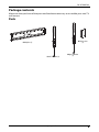
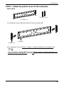
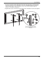
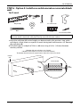
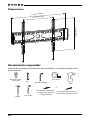
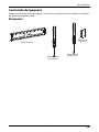
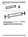
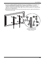
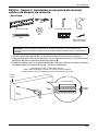
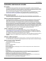
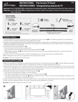
Dynex DX-DTVMFP23 es un soporte de pared para TV de bajo perfil con una construcción de acero resistente que puede soportar televisores desde 37" a 90" y hasta 165 libras.
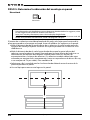
Este soporte es compatible con patrones VESA comunes, incluidos 200×200, 300×200, 400×200, 400×300, 400×400, 500×400 y 600×400 mm.
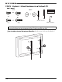
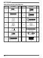
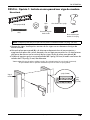
También incluye una variedad de accesorios de montaje para adaptarse a una amplia gama de televisores.
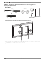
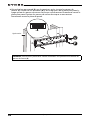
Con su diseño de bajo perfil y fácil instalación, el Dynex DX-DTVMFP23 es una excelente opción para montar tu televisor de forma segura en la pared.
Dynex DX-DTVMFP23 es un soporte de pared para TV de bajo perfil con una construcción de acero resistente que puede soportar televisores desde 37" a 90" y hasta 165 libras.
Este soporte es compatible con patrones VESA comunes, incluidos 200×200, 300×200, 400×200, 400×300, 400×400, 500×400 y 600×400 mm.
También incluye una variedad de accesorios de montaje para adaptarse a una amplia gama de televisores.
Con su diseño de bajo perfil y fácil instalación, el Dynex DX-DTVMFP23 es una excelente opción para montar tu televisor de forma segura en la pared.


-
 1
1
-
 2
2
-
 3
3
-
 4
4
-
 5
5
-
 6
6
-
 7
7
-
 8
8
-
 9
9
-
 10
10
-
 11
11
-
 12
12
-
 13
13
-
 14
14
-
 15
15
-
 16
16
-
 17
17
-
 18
18
-
 19
19
-
 20
20
-
 21
21
-
 22
22
-
 23
23
-
 24
24
-
 25
25
-
 26
26
-
 27
27
-
 28
28
-
 29
29
-
 30
30
-
 31
31
-
 32
32
-
 33
33
-
 34
34
-
 35
35
-
 36
36
-
 37
37
-
 38
38
-
 39
39
-
 40
40
-
 41
41
-
 42
42
-
 43
43


Dynex DX-DTVMFP23 Guía de instalación
- Categoría
- Soportes de pared para panel plano
- Tipo
- Guía de instalación
Dynex DX-DTVMFP23 es un soporte de pared para TV de bajo perfil con una construcción de acero resistente que puede soportar televisores desde 37" a 90" y hasta 165 libras.
Este soporte es compatible con patrones VESA comunes, incluidos 200×200, 300×200, 400×200, 400×300, 400×400, 500×400 y 600×400 mm.
También incluye una variedad de accesorios de montaje para adaptarse a una amplia gama de televisores.
Con su diseño de bajo perfil y fácil instalación, el Dynex DX-DTVMFP23 es una excelente opción para montar tu televisor de forma segura en la pared.
en otros idiomas
- English: Dynex DX-DTVMFP23 Installation guide
Artículos relacionados
-
Dynex DX-HTMT0120 guía de instalación rápida
-
Dynex DX-HTMF1620 guía de instalación rápida
-
-
-
-
-
-
-
-
Otros documentos
-
Insignia NS-HTVMFAB Manual de usuario
-
RocketFish RF-HTMT15 Template
-
Sanus VLF515 Guía de instalación
-
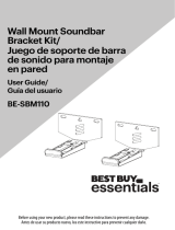 BEST BUY essentials BE-SBM110 Guía del usuario
-
-
-
 Utilitech UT70C Guía de instalación
-
 Dreambaby L860 Manual de usuario
-
Klip Xtreme KTM-956 El manual del propietario


