
VERMEIREN
INSTALLATION MANUAL
MANUEL D'INSTALLATION
INSTALLATIEHANDLEIDING
INSTALLATIONSANLEITUNG
MANUALE DI INSTALLAZIONE
MANUAL DE INSTALACIÓN
INSTRUKCJA INSTALACJI
PŘÍRUČKU PRO INSTALACI
Trigo S
Trigo T

Instrukcje dla wyspecjalizowanego
All rights reserved, including translation.
No part of this manual may be reproduced in any form what so
ever (print, photocopy, microfilm or any other process) without
written permission of the publisher, or processed, duplicated or
distributed by using electronic systems.
Tous droits réservés, y compris la traduction.
Aucune partie de ce manuel ne peut être reproduite, sous
quelque forme que ce soit (imprimée, photocopie, microfilm ou
tout autre procédé) sans l'autorisation écrite du publicateur, ni
traitée, dupliquée ou distribuée à l'aide de systèmes
électroniques.
Alle rechten, inclusief vertaling, voorbehouden.
Niets uit deze handleiding mag geheel of gedeeltelijk in enige
vorm (druk, fotokopie, microfilm of ieder ander procedé) zonder
de schriftelijke toelating van de uitgever worden
gereproduceerd of met behulp van elektronische systemen
worden verwerkt, gekopieerd of verspreid.
Alle Rechte, auch an der Übersetzung, vorbehalten.
Kein Teil der Gebrauchsanweisung darf in irgendeiner Form
(Druck, Fotokopie, Mikrofilm oder einem anderen Verfahren)
ohne schriftliche Genehmigung des Herausgebers
reproduziert oder unter Verwendung elektronischer Systeme
verarbeitet, vervielfältigt oder verbreitet werden.
Tutti i diritti riservati (anche sulla traduzione).
Il presente manuale non può essere riprodotto, neppure
parzialmente, con alcun mezzo (stampa, fotocopia, microfilm o
altro procedimento) senza l’autorizzazione scritta della casa
produttrice, né elaborato, duplicato o distribuito con l’ausilio di
sistemi elettronici.
Todos los derechos reservados, incluidos los de la
traducción.
Se prohíbe la reproducción total o parcial del presente manual
de cualquier forma (impresión, fotocopia, microfilm o cualquier
otro procedimiento), así como la edición, copia o distribución
empleando sistemas electrónicos, sin el permiso escrito del
editor.
Wszelkie prawa zastrzeżone, łącznie z tłumaczeniem.
Żadna część niniejszej instrukcji nie może być powielana w
jakiejkolwiek formie (drukowanej, fotokopii, mikrofilmu ani
innej) bez pisemnej zgody wydawcy, nie może być również
przetwarzana, kopiowana ani rozprowadzana za pomocą
systemów elektronicznych.
Všechna práva vyhrazena, včetně překladu.
Šíření jakékoliv části tohoto katalogu jakýmkoliv způsobem
(tisk, kopie, mikrofilm nebo jiný způsob) bez písemného
souhlasu vydavatele, nebo zpracování, duplikace či distribuce
prostřednictvím elektronických systémů je zakázáno.
EN
Instructions for specialist dealer
This instruction manual is part and parcel of the
product and must accompany every product
sold.
Version: D, 2021-04
FR
Instructions pour les distributeurs
Ce manuel d'instructions fait partie du produit et
doit accompagner chaque produit vendu.
Version : D, 2021-04
NL
Instructies voor de vakhandelaar
Deze handleiding is deel van het product en
dient bij iedere product te worden geleverd.
Versie: D, 2021-04
DE
Hinweise für den Fachhändler
Diese Gebrauchsanweisung ist Bestand-teil des
Produkts und ist bei jeder Produkts
auszuhändigen.
Version: D, 2021-04
IT
Istruzioni per il rivenditore
Il presente Manuale di istruzioni è parte
integrante del prodotto e deve essere fornito
assieme alla prodotto.
Versione: D, 2021-04
ES
Instrucciones destinadas a los distribuidores
especializados
El presente manual de instrucciones es parte
integrante del producto y se debe adjuntar a
todas las producto que se vendan.
Versión: D, 2021-04
PL
sprzedawcy
Niniejsza instrukcja obsługi jest nieodłączną
częścią produktu i musi być dołączona do
każdego sprzedawanego produktu.
Wersja: D, 2021-04
CS
Pokyny pro specializovaného prodejce
Tento návod k obsluze je součástí dodávky a
musí být součástí každého prodaného
produktu.
Verze: D, 2021-04
Basic UDI: 5415174 122106Trigo S TV
5415174 122106Trigo T TX
Multi version: D, 2021-04

Trigo S, Trigo T
2021-04
Content
1
EN
NL
PL
CS
Content
Preface........................................................................................................................ 2
1 This product .................................................................................................. 3
2 Scope of delivery .......................................................................................... 4
3 Assembly and adjustments ......................................................................... 5
3.1 Tools ............................................................................................................... 5
3.2 Adjusting the wheelchair to the user ............................................................... 6
3.2.1 Seat height ...............................................................................................6
3.2.2 Rear wheel position .................................................................................7
3.2.3 Seat inclination ........................................................................................7
3.2.4 Backrest inclination ..................................................................................7
3.2.5 Removable side plate ..............................................................................8
3.2.6 Fixed side plate ........................................................................................8
3.2.7 Camber angle adjustment of the rear wheels ..........................................9
3.2.8 Footplate height .......................................................................................9
3.2.9 Footplate angle ........................................................................................9
3.2.10 Footplate depth (only for Trigo S, folding footplate) ............................... 10
3.2.11 Adjusting the parking brakes .................................................................. 10
3.3 Changing pneumatic tyres ............................................................................ 11

Trigo S, Trigo T
2021-04
Preface
2
EN
NL
PL
CS
Preface
To support you on the installation and repairs of this manual wheelchair, we provide you with this
installation manual. Please read it carefully. If you still have questions after reading this manual,
do not hesitate to contact Vermeiren.
The information in this manual applies to the following wheelchair(s):
• Trigo S with all its configurations
• Trigo T with all its configurations
Important note
Pictures of the product are used to clarify the instructions. Details of the shown product may
deviate from your product.
Available information
On our website http://www.vermeiren.com/ you will always find the most recent version of the
following information. Please consult this website regularly for possible updates.
Visually impaired people can download the electronic version of this manual and have it read out
by means of a text-to-speech software application.
User manual
For user and specialist dealer
Installation manual
For specialist dealer
Service manual for wheelchairs
For specialist dealer
Drawings of (spare) parts
For specialist dealer
EC declaration of conformity

Trigo S, Trigo T
2021-04
Content
3
EN
NL
PL
CS
1 This product
1. Backrest
2. Side plate (with optional
armrest)
3. Seat
4. Frame
5. Fixed footplate 1x (Trigo S)
6. Removable footplate 2x
(Trigo T)
7. Front wheel
8. Rear wheel
9. Fixed footrest (Trigo S)
10. Removable footrest
(Trigo T)
11. Brake
12. Push handle (optional)
13. Hand rim
14. Identification plate
1
6
4
14
13
11
3
10
12
7
2
8
13
2
9
5
4
7
14
8
11
1
3

Trigo S, Trigo T
2021-04
Scope of delivery
4
EN
NL
PL
CS
2 Scope of delivery
The following items are part of the delivery:
• Framework
• Sideplates
• Rear and front wheels
• Seat and back cushion
• Footrests (*)
• Tools
• User manual of wheelchair
• Accessories (if applicable)
Before use, check if everything is included and that no products are damaged.
Please note that the basic configuration may differ in different European countries. Contact your
specialist dealer.
(*) Fixed for Trigo S, removable for Trigo T.

Trigo S, Trigo T
2021-04
Content
5
EN
NL
PL
CS
3 Assembly and adjustments
Important remarks
• The Trigo wheelchair has multiple configuration options and optional parts.
• Read the user manual of this wheelchair.
• Be aware of the technical details and limits of intended use; see the user manual.
• For more information, contact your nearest Vermeiren facility.
3.1 Tools
To (dis)assemble and adjust the wheelchair, the following tools are needed:
• Wrench set no. 8
• Allen keyset n° 2.5, 3, 4 and 5
Risk of injuries or damage
• The wheelchair needs to be (dis)assembled and adjusted by a specialist dealer according to
the instructions in this chapter.
• Only use parts and tools described in this manual.
• Prevent bystanders from accessing the (dis)assembling area.
• Keep the (dis)assembling area clean and tidy, to prevent falling.
• Collect all small parts in a box or bag.
• While (dis)assembling and operating the wheelchair, make sure no objects or body parts get
caught between moving parts.
• Make sure all screws are firmly secured before driving.
CAUTION

Trigo S, Trigo T
2021-04
Assembly and adjustments
6
EN
NL
PL
CS
3.2 Adjusting the wheelchair to the user
3.2.1 Seat height
The seat can be raised or lowered by changing the wheel position, diameter of the front wheels,
and diameter of the rear wheels.
To adjust the height of the rear wheel:
1. Remove the rear wheel, using the quick release system.
2. Remove both bolt-nut connections (1) from the rear wheel
attachment cube (2).
3. Slide the attachment cube (2) up/down in the rear wheel support
(3) until the desired height.
4. Fasten the attachment cube (2) by firmly tightening both
bolt-nut (1) connections.
5. Remount the rear wheel.
6. Repeat for the other wheel.
To adjust the height of the front wheel:
1. Remove the M6 screws (4) on both sides of the wheel.
2. Move the wheel up/down in the front fork (5) until the desired
position.
3. Reattach the wheel to the front fork (5) by firmly tightening both
screws (4) in the according hole.
4. Repeat for the other wheel. Make sure that both rear wheels and
both front wheels are adjusted to the same height.
To adjust the angle of the front wheels:
1. Remove the cover (6) of the front wheel attachment.
2. Loosen the M8 screw.
3. Adjust the angle of the front wheel using the toothed clamp (7). The
fork attachment (8) should be perpendicular to the ground.
4. Firmly retighten the M8 screw and place back the cover (6).
5. Repeat for the other wheel. Make sure that both wheels are adjusted to the same angle.
Risk of injuries
• Take the possible rear wheel-front wheel configurations into account regarding seat height, as
mentioned in Table 1.
• Make sure that both front wheels and both rear wheels are mounted in the same position.
CAUTION
1
2
3
6
4
8
7
5

Trigo S, Trigo T
2021-04
Content
7
EN
NL
PL
CS
Table 1: Wheel configurations regarding seat height
SEAT HEIGHT FRONT (in mm)
380
390
400
410
420
430
440
450
460
470
480
490
500
510
3"
¡
¡
¡
¡
¡
¡
¡
¡
¡
4"
¡
¡
¡
¡
¡
¡
¡
¡
¡
¡
¡
5"
¡
¡
¡
¡
¡
¡
¡
¡
¡
¡
6"
¡
¡
¡
¡
¡
¡
¡
¡
¡
SEAT HEIGHT REAR (in mm)
315
325
335
345
355
365
375
385
395
405
415
425
435
445
455
465
475
485
495
505
515
18"
¡
¡
¡
¡
¡
¡
¡
¡
¡
¡
¡
20"
¡
¡
¡
¡
¡
¡
¡
¡
¡
¡
¡
22"
¡
¡
¡
¡
¡
¡
¡
¡
¡
¡
¡
¡
24"
¡
¡
¡
¡
¡
¡
¡
¡
¡
¡
¡
¡
26"
¡
¡
¡
¡
¡
¡
¡
¡
¡
¡
¡
¡
3.2.2 Rear wheel position
The rear wheel position can be steplessly adjusted:
1. Remove the rear wheel, using the quick release
system.
2. On the inside of the rear wheel support (9), loosen the
two M6 screws at the top, and the three M6 screws on
the bottom a few turns until the support can be moved..
3. Using the measurements (10) on the outside of the
seat frame, slide the rear wheel support (9) evenly to
the back/front of the frame until the desired depth is
reached.
4. Firmly tighten the five M6 screws.
5. Repeat on the other side, using the measurements (10) on the frame to make sure both
rear wheel supports are adjusted to the same depth.
3.2.3 Seat inclination
The seat inclination can be adjusted by altering the configuration of the front and rear wheels.
See 3.2.1 for the instructions on how to change the position of the wheels.
3.2.4 Backrest inclination
The backrest can be adjusted into 5 angle positions:
1. Gently pull the back strap (11) until the backrest is unlocked.
2. Remove the outer screw (12) of the hinging point (13).
3. Move the inner sleeve with second screw to another hole,
according to the desired angle. Lock the position by retightening
the screw (12).
4. Repeat for the second backrest connection.
5. Check the position by moving the backrest until it is locked into
place by the locking pins. Make sure that both locking pins are
secured in the same position.
10
9
13
11
12

Trigo S, Trigo T
2021-04
Assembly and adjustments
8
EN
NL
PL
CS
3.2.5 Removable side plate
Depth of panel (16)
1. Loosen socket screw (14) and remove socket screw (15).
2. Slide side panel (16) forward/backward and retighten
with socket screw (15) in one of the openings of the
support. Tighten socket screw (14) again.
3. Repeat for the other side panel.
Height of panel (16)
1. Loosen socket screw (15), remove socket screw (14).
2. Slide side panel (16) up/down and retighten with socket
screw (14) in one of the openings of the support. Tighten
socket screw (15) again.
3. Repeat for the other side panel.
Height of complete side plate (18)
1. Remove the side plate from the wheelchair.
2. Remove the socket screw (17).
3. Place the socket screw in another hole according to the
desired height (5 positions available).
4. Firmly tighten the socket screw.
5. Repeat the adjustments above for the second side plate.
Make sure that both side plates and panels are set to the same
height and depth, and that they are firmly secured.
3.2.6 Fixed side plate
Depth of side plate (22)
1. Loosen socket screws (19+20+21).
2. Slide side plate forward/backward and retighten the
socket screws.
Height of side plate (22)
1. Remove socket screws (19+20+21).
2. Move the side plate up/down to the desired height and
retighten it with socket screws (19+20) in one of its
openings. Replace socket screw 21 accordingly.
Repeat the adjustments above for the second side plate.Make sure that both side plates are set
to the same height and dept, and that they are firmly secured.
16
17
14
15
21
20
19
22
17
18

Trigo S, Trigo T
2021-04
Content
9
EN
NL
PL
CS
3.2.7 Camber angle adjustment of the rear wheels
The camber angle of the rear wheels is adjustable in 4 positions (0°, 2°, 4°, 6°) by adjusting the
angle of the rear wheel attachment cube in the rear wheel support:
1. Remove the rear wheel, using the quick release system.
2. Remove both bolt-nut connections (23) from the rear wheel
attachment cube (24).
3. Adjust the angle of the attachment cube (24) relative to the rear
wheel support (25). *
4. Fasten the attachment cube (24) in the correct angle by firmly
tightening the bolt-nut (23) connections in the corresponding
holes.
5. Remount the rear wheel.
6. Repeat for the other wheel. Make sure that both rear wheels are adjusted to the same
camber angle.
The attachment cube has been fitted with four sets of two matching
holes. Choose the set that corresponds to the required camber angle as
shown in the picture.
3.2.8 Footplate height
Trigo S (steps of 10 mm)
1. Remove the M6 screw from the back of the footrest (26).
2. Slide the footplate (27) up/down in the front-frame tube (28)
until the desired height. Make sure the holes of the inner and
outer tube align.
3. Replace the M6 screw (26).
4. Repeat for the second footrest. Make sure that both footrests
are set to the same height, and that they are firmly secured.
Trigo T (stepless)
1. Remove the M6 screw from the back of the footrest (26).
2. Slide the footplate (27) up/down in the front-frame tube (28)
until the desired height.
3. Replace the M6 screw (26).
4. Repeat for the second footrest. Make sure that both footrests are set to the same height,
and that they are firmly secured.
3.2.9 Footplate angle
Trigo T (20° in steps of 5°)
1. Loosen the M6 screw (29) on the outside of the footplate.
2. Turn the footplate to the desired angle. The angle indication
is given according to dashes on the outside of the toothed
clamp.
3. Retighten the M6 screw (29) firmly.
4. Repeat for the second footplate. Make sure that both
footplates are firmly secured.
*
27
3
28
26
23
24
25
29

Trigo S, Trigo T
2021-04
Assembly and adjustments
10
EN
NL
PL
CS
Trigo S (stepless)
For the foldable footplate:
1. On the bottom of the footplate, loosen both M6 screws (30).
2. Turn the footplate until the desired angle is reached.
3. Firmly tighten both screws (30).
For the opening footplate:
1. On the main tube (31), loosen the M6 screws (32) on both sides of
the footplate.
2. Turn the footplate until the desired angle is reached.
3. Firmly retighten both screws (32).
3.2.10 Footplate depth (only for Trigo S, folding footplate)
1. Remove the four M5 screws (33) from the footplate.
2. Place the footplate forwards/backwards to the desired
depth (2 positions available).
3. Firmly retighten the M5 screws (33). Make sure that the
footplate is frimly secured.
3.2.11 Adjusting the parking brakes
Depending on the diameter of the rear wheels and their position, the brakes can be adjusted
accordingly. The following instructions apply to both the push-pull brakes and the sports brakes.
1. Release the brake, see user manual.
2. Loosen the two screws (34) connecting the brake to
the frame.
3. Slide the brake forwards/backwards in the slot until
the desired position.
4. Firmly retighten both screws.
5. Verify if the brake is working properly; the wheel is
blocked, but the brake can still be operated easily.
If this is not the case, repeat the steps above until
the brake is adjusted well.
6. Repeat for the second parking brake. Make sure
that both brakes are adjusted identically.
30
33
34
32
31

Trigo S, Trigo T
2021-04
Content
11
EN
NL
PL
CS
3.3 Changing pneumatic tyres
Risk of injuries and damage
• Make sure all air is released from the tyre, before removing it.
• Make sure that no body parts, the inner tube nor any other objects are pinched between tyre
and rim.
• Make sure all screws are firmly secured by hand before driving with the wheelchair.
• Make sure that the pressure is correct, see the pressure indication on the tyres.
• Inflate the tyre using inflating equipment which complies to regulations and with a pressure
indication in “bar”.
• Only use replacement parts approved by Vermeiren.
To change the tyre or inner tube, proceed as follows:
1. Let all the air out of the inner tube.
2. Insert a tyre lever between de tyre and the rim.
3. Gently push the tyre lever downwards. This will pull the tyre over the edge of the rim.
4. Move the lever along the rim so the tyre pops out.
5. Carefully remove the tyre from the rim and remove the tube.
Place the rim belt in position over the air valve before inserting it into the rim. The
rim belt can now be pulled over easily. Check that all spoke heads are covered (a
rim belt is not required in the case of a plastic rim).
Push the tyre over the edge of the rim, starting behind the air valve. Inflate the tube
slightly until it is round, and place it inside the tyre.
If the tube fits inside the tyre without any folds (in case of folds: let out some air),
then the upper side of the tyre can be pressed lightly onto the rim with both hands,
starting at the air valve. Lightly push the air valve inwards and pull it out again to
make sure that the tyre is positioned properly in the region of the air valve.
CAUTION


Trigo S, Trigo T
2021-04
Table des matières
1
EN
FR
NL
Table des matières
Préface........................................................................................................................ 2
1 Ce produit ...................................................................................................... 3
2 Portée de la livraison .................................................................................... 4
3 Montage et réglages ..................................................................................... 5
3.1 Outils ............................................................................................................... 5
3.2 L'adaptation du fauteuil à l'utilisateur .............................................................. 6
3.2.1 Hauteur du siège .....................................................................................6
3.2.2 Position de la roue arrière ........................................................................7
3.2.3 Inclination du siège ..................................................................................7
3.2.4 Inclinaison du dossier ..............................................................................7
3.2.5 Plaque latérale amovible ..........................................................................8
3.2.6 Plaque latérale fixe ..................................................................................8
3.2.7 Réglage de l’angle de carrossage des roues arrière................................9
3.2.8 Hauteur de palette repose-pieds ..............................................................9
3.2.9 Inclinaison du repose-pied .......................................................................9
3.2.10 Profondeur de palette repose-pieds (uniquement pour Trigo S, palette
repose-pieds pliable) ....................................................................................... 10
3.2.11 Réglage des freins de stationnement..................................................... 10
3.3 Changer les pneumatiques .......................................................................... 11

Trigo S, Trigo T
2021-04
Préface
2
EN
FR
NL
Préface
Nous vous fournissons ce manuel d'installation pour vous soutenir dans l'installation et les
réparations de ce fauteuil roulant manuel. Veuillez le lire attentivement. Si vous avez encore des
questions après la lecture de ce manuel, n’hésitez pas à prendre contact avec Vermeiren.
Les informations fournies dans ce manuel s'appliquent au(x) fauteuil(s) roulant(s) :
• Trigo S avec toutes ses configurations
• Trigo T avec toutes ses configurations
Remarque importante
Les photos du produit sont utilisées pour clarifier les instructions. Les détails du produit illustré
peuvent diverger de votre produit.
Informations disponibles
Sur notre site http://www.vermeiren.com/ vous trouverez toujours la version la plus récente des
informations suivantes. Veuillez consulter régulièrement ce site Internet pour connaître les
éventuelles mises à jour.
Les personnes malvoyantes peuvent télécharger la version électronique de ce manuel et la lire
au moyen d'une application de texte-parole.
Manuel d'utilisation
Pour l'utilisateur et le revendeur spécialisé
Manuel d'installation
Pour le revendeur spécialisé
Manuel d'entretien des fauteuils roulants
Pour le revendeur spécialisé
Dessins des pièces (de rechange)
Pour le revendeur spécialisé
Déclaration de conformité CE

Trigo S, Trigo T
2021-04
Table des matières
3
EN
FR
NL
1 Ce produit
1. Dossier
2. Plaque latérale (avec
accoudoir en option)
3. Siège
4. Cadre
5. Palette repose-pieds fixe 1x
(Trigo S)
6. Palette repose-pieds
amovible 2x (Trigo T)
7. Roue avant
8. Roue arrière
9. Repose-pieds fixe (Trigo S)
10. Repose-pieds amovible
(Trigo T)
11. Frein
12. Poignée de poussée (en
option)
13. Main courante
14. Plaque d'identification
1
6
4
14
13
11
3
10
12
7
2
8
13
2
9
5
4
7
14
8
11
1
3

Trigo S, Trigo T
2021-04
Portée de la livraison
4
EN
FR
NL
2 Portée de la livraison
Les éléments suivants sont compris dans la livraison :
• Cadre
• Plaques latérales
• Roues arrière et avant
• Coussin du siège et dossier
• Repose-pieds (*)
• Outils
• Manuel d'utilisation du fauteuil roulant
• Accessoires (le cas échéant)
Avant utilisation, vérifiez que tout est inclus et qu'aucun produit n'est endommagé.
Veuillez noter que la configuration de base peut différer dans les différents pays européens.
Prenez contact avec votre revendeur spécialisé.
(*) Fixe pour Trigo S, amovible pour Trigo T.

Trigo S, Trigo T
2021-04
Table des matières
5
EN
FR
NL
3 Montage et réglages
Remarques importantes
• Le fauteuil roulant Trigo possède différentes options de configuration et pièces en option.
• Lisez le manuel d'utilisation de ce fauteuil roulant.
• Veuillez garder à l’esprit les détails techniques et les limites de l'utilisation prévue ; cf. le manuel
d'utilisation.
• Pour de plus amples informations, prenez contact avec l'établissement Vermeiren le plus
proche.
3.1 Outils
Pour (dé)monter et régler le fauteuil roulant, les outils suivants sont nécessaires :
• Jeu de clés à molette n° 8
• Jeu de clés Allen n° 2.5, 3, 4 et 5
Risque de blessures ou de dommages
• Le fauteuil roulant doit être (dé)monté et réglé par un revendeur spécialisé conformément aux
instructions fournies dans le présent chapitre.
• N'utilisez que les pièces et outils décrits dans ce manuel.
• Assurez-vous qu'aucune personne aux alentours ne pénètre dans la zone de (dé)montage.
• Gardez la zone de (dé)montage propre et ordonnée pour éviter toute chute.
• Rassemblez toutes les petites pièces dans une boîte ou un sac.
• Lors du (dé)montage et de l'utilisation du fauteuil roulant, assurez-vous de ne coincer aucun
objet ni aucune partie du corps entre les pièces mobiles.
• Assurez-vous que toutes les vis sont correctement serrées avant l’utilisation.
ATTENTION

Trigo S, Trigo T
2021-04
Montage et réglages
6
EN
FR
NL
3.2 L'adaptation du fauteuil à l'utilisateur
3.2.1 Hauteur du siège
Le siège peut être relevé ou abaissé en changeant la position de la roue, le diamètre des roues
avant et celui des roues arrière.
Pour régler la hauteur de la roue arrière :
1. Retirez la roue arrière à l’aide système de déverrouillage rapide.
2. Retirez les deux raccords boulon-écrou (1) du cube de fixation
de la roue arrière (2).
3. Faites glisser le cube de fixation (2) vers le haut/bas dans le
support de roue arrière (3) jusqu’à la hauteur désirée.
4. Serrez le cube de fixation (2) en serrant fermement les deux
raccords boulon-écrou (1).
5. Remontez la roue arrière.
6. Répétez cette opération pour l’autre roue.
Pour régler la hauteur de la roue avant :
1. Retirez les vis M6 (4) des deux côtés de la roue.
2. Faites glisser la roue vers le haut/bas dans la fourche avant (5)
jusqu’à la position désirée.
3. Refixez la roue sur la fourche avant (5) en serrant fermement les
deux vis (4) dans le trou correspondant.
4. Répétez cette opération pour l’autre roue. Assurez-vous que les
deux roues avant et arrière sont bien réglées à la même hauteur.
Pour régler l’angle des roues avant :
1. Retirez le couvercle (6) de la fixation de la roue avant.
2. Desserrez la vis M8.
3. Réglez l'angle de la roue avant en utilisant le dispositif denté (7). La
fixation de la fourche (8) doit être perpendiculaire par rapport au sol.
4. Resserrez fermement la vis M8 et remettez le couvercle en place (6).
5. Répétez cette opération pour l’autre roue. Assurez-vous que les deux roues sont réglées
sous le même angle.
Risque de blessures
• Tenez compte des configurations de roues avant et arrière pour la hauteur de siège, comme
mentionné dans Tableau 1.
• Assurez-vous que les deux roues avant et arrière sont montées dans la même position.
ATTENTION
1
2
3
6
4
8
7
5

Trigo S, Trigo T
2021-04
Table des matières
7
EN
FR
NL
Tableau 1 : Configurations de roues par rapport à la hauteur du siège
HAUTEUR DE SIÈGE AVANT (en mm)
380
390
400
410
420
430
440
450
460
470
480
490
500
510
3"
¡
¡
¡
¡
¡
¡
¡
¡
¡
4"
¡
¡
¡
¡
¡
¡
¡
¡
¡
¡
¡
5"
¡
¡
¡
¡
¡
¡
¡
¡
¡
¡
6"
¡
¡
¡
¡
¡
¡
¡
¡
¡
HAUTEUR DE SIÈGE ARRIÈRE (en mm)
315
325
335
345
355
365
375
385
395
405
415
425
435
445
455
465
475
485
495
505
515
18"
¡
¡
¡
¡
¡
¡
¡
¡
¡
¡
¡
20"
¡
¡
¡
¡
¡
¡
¡
¡
¡
¡
¡
22"
¡
¡
¡
¡
¡
¡
¡
¡
¡
¡
¡
¡
24"
¡
¡
¡
¡
¡
¡
¡
¡
¡
¡
¡
¡
26"
¡
¡
¡
¡
¡
¡
¡
¡
¡
¡
¡
¡
3.2.2 Position de la roue arrière
La position de la roue arrière peut être réglée progressivement:
1. Retirez la roue arrière à l’aide du système de
déverrouillage rapide.
2. À l'intérieur du support de roue arrière (9), desserrez
de quelques tours les deux vis M6 du dessus et les
trois vis M6 du dessous jusqu’à pouvoir retirer le
support.
3. En utilisant les mesures (10) à l’extérieur du cadre de
siège, faites glisser le support de roue arrière (9)
uniformément jusqu’à l’arrière/avant du cadre jusqu’à
obtenir la profondeur désirée.
4. Serrez fermement les cinq vis M6.
5. Répétez l’opération de l’autre côté, en se basant sur les mesures (10) du cadre pour
s’assurer que les deux supports de roue arrière sont réglés à la même profondeur.
3.2.3 Inclination du siège
L'inclinaison du siège peut être réglée en modifiant la configuration des roues avant et arrière.
Voir 3.2.1 pour les instructions sur la façon de modifier la position des roues.
3.2.4 Inclinaison du dossier
Le dossier peut être réglé dans 5 angles différents :
1. Tirez délicatement la sangle arrière (11) jusqu’à ce que le dossier
soit déverrouillé.
2. Retirez la vis extérieure (12) du point d’articulation (13).
3. Retirez le manchon intérieur avec la deuxième vis dans un autre
trou, selon l’angle désiré. Verrouillez la position en resserrant la
vis (12).
4. Répétez l’opération pour le deuxième raccord de dossier.
5. Vérifiez la position en déplaçant le dossier jusqu'à ce qu'il soit
verrouillé en place par les goupilles d'arrêt. Assurez-vous que les
deux goupilles d'arrêt sont bien serrées dans la même position.
10
9
13
11
12

Trigo S, Trigo T
2021-04
Montage et réglages
8
EN
FR
NL
3.2.5 Plaque latérale amovible
Profondeur du panneau (16)
1. Desserrez la vis à six pans (14) et retirez la vis à six pans
(15).
2. Faites glisser le panneau latéral (16) vers l'avant/arrière
et resserrez avec la vis à six pans (15) dans l'une des
ouvertures du support. Resserrez les vis à six pans
(14).
3. Répétez l'opération pour l’autre panneau latéral.
Hauteur du panneau (16)
1. Desserrez la vis à six pans (15), retirez la vis à six pans
(14).
2. Faites glisser le panneau latéral (16) vers le haut/bas et
resserrez avec la vis à six pans (14) dans l'une des
ouvertures du support. Resserrez les vis à six pans (15).
3. Répétez l'opération pour l’autre panneau latéral.
Hauteur de la plaque latérale complète (18)
1. Retirez la plaque latérale du fauteuil roulant.
2. Retirez la vis à six pans (17).
3. Placez la vis à six pans dans un autre trou selon la hauteur
désirée (5 positions disponibles).
4. Serrez fermement la vis à six pans.
5. Répétez les réglages au-dessus de la deuxième plaque
latérale.
Assurez-vous que les deux plaques latérales et les panneaux sont réglés à la même hauteur et
profondeur, et qu'ils sont fermement fixés.
3.2.6 Plaque latérale fixe
Profondeur de plaque latérale (22)
1. Desserrez les vis à six pans (19+20+21).
2. Faites glisser la plaque latérale vers l'avant/arrière et
serrez les vis à six pans.
Hauteur de la plaque latérale (22)
1. Retirez les vis à six pans (19+20+21).
2. Déplacez la plaque latérale vers le haut/bas à la
hauteur désirée et resserrez-la avec les vis à six pans
(19+20) dans l'une de ses ouvertures. Remplacez les
vis à six pans 21 en conséquence.
Répétez les réglages ci-dessus pour la deuxième plaque latérale. Assurez-vous que les deux
plaques latérales sont réglées à la même hauteur et profondeur et qu’elles sont bien serrées.
16
17
14
15
21
20
19
22
17
18

Trigo S, Trigo T
2021-04
Table des matières
9
EN
FR
NL
3.2.7 Réglage de l’angle de carrossage des roues arrière
L’angle de carrossage des roues arrière peut être réglé dans 4 positions (0°, 2°, 4°, 6°) en réglant
l’angle du cube de fixation de la roue arrière dans le support de roue arrière :
1. Retirez la roue arrière à l’aide système de déverrouillage rapide.
2. Retirez les deux raccords boulon-écrou (23) du cube de fixation
de la roue arrière (24).
3. Réglez l’angle du cube de fixation (24) par rapport au support
de roue arrière (25). *
4. Serrez le cube de fixation (24) dans l’angle correct en serrant
fermement les raccords boulon-écrou (23) dans les trous
correspondants.
5. Remontez la roue arrière.
6. Répétez cette opération pour l’autre roue. Assurez-vous que les
deux roues arrière sont réglées sous le même angle de carrossage.
Le cube de fixation est doté de quatre jeux de deux trous d’alignement.
Choisissez le jeu qui correspond à l’angle de carrossage requis comme
indiqué sur l'illustration.
3.2.8 Hauteur de palette repose-pieds
Trigo S (pas de 10 mm)
1. Retirez la vis M6 de l’arrière du repose-pieds (26).
2. Faites glisser la palette repose-pieds (27) vers le haut/bas
dans le tube du cadre avant (28) jusqu'à la hauteur désirée.
Assurez-vous que les trous du tube intérieur et extérieur sont
alignés.
3. Remplacez la vis M6 (26).
4. Répétez cette opération pour l’autre repose-pied. Assurez-
vous que les deux repose-pieds sont réglés à la même
hauteur et qu'ils sont fermement fixés.
Trigo T (en continu)
1. Retirez la vis M6 de l’arrière du repose-pieds (26).
2. Faites glisser la palette repose-pieds (27) vers le haut/bas dans le tube du cadre avant (28)
jusqu'à la hauteur désirée.
3. Remplacez la vis M6 (26).
4. Répétez cette opération pour l’autre repose-pied. Assurez-vous que les deux repose-pieds
sont réglés à la même hauteur et qu'ils sont fermement fixés.
3.2.9 Inclinaison du repose-pied
Trigo T (20° par échelons de 5°)
1. Desserrez la vis M6 (29) à l’extérieur de la palette repose-
pieds.
2. Tournez la palette repose-pieds dans l’angle désiré.
L’inclinaison de l’angle est indiquée par des pointillés sur le
dispositif denté.
3. Resserrez fermement la vis M6 (29).
4. Répétez l'opération pour la deuxième palette repose-pied.
Assurez-vous que les deux palettes sont bien fixées.
*
27
3
28
26
23
24
25
29

Trigo S, Trigo T
2021-04
Montage et réglages
10
EN
FR
NL
Trigo S (en continu)
Pour la palette repose-pieds pliable :
1. Dans le bas de la palette repose-pieds, desserrez les deux vis
M6 (30).
2. Tournez la palette repose-pieds jusqu’à obtention de l’angle
désiré.
3. Serrez fermement les 2 vis (30).
Pour l’ouverture de la palette repose-pieds :
1. Sur le tube principal (31), desserrez les vis M6 (32) sur les deux
côtés de la palette repose-pieds.
2. Tournez la palette repose-pieds jusqu’à obtention de l’angle
désiré.
3. Resserrez fermement les 2 vis (32).
3.2.10 Profondeur de palette repose-pieds (uniquement pour Trigo S, palette repose-pieds
pliable)
1. Retirez les quatre vis M5 (33) de la palette repose-pieds.
2. Placez la palette repose-pieds vers l'avant/arrière dans
la profondeur désirée (2 positions disponibles).
3. Resserrez fermement les vis M5 (33). Assurez-vous que
la palette repose-pieds est bien serrée.
3.2.11 Réglage des freins de stationnement
Suivant le diamètre des roues arrière et leur position, les freins peuvent être réglés en
conséquence. Les instructions suivantes s’appliquent tant aux freins à pousser-tirer qu’aux freins
de sport.
1. Relâchez le frein, voir le manuel d'utilisation.
2. Desserrez les deux vis (34) reliant le frein au cadre.
3. Faites glisser le frein vers l’avant/arrière dans la
fente jusqu'à la position désirée.
4. Resserrez fermement les deux vis.
5. Vérifiez si le frein fonctionne convenablement : la
roue est bloquée, mais le frein peut toujours être
actionné facilement. Si ce n’est pas le cas, répétez
les étapes ci-dessus jusqu'à ce que le frein soit bien
réglé.
6. Répétez cette opération pour le deuxième frein de
stationnement. Assurez-vous que les deux freins
sont réglés identiquement.
30
33
34
32
31

Trigo S, Trigo T
2021-04
Table des matières
11
EN
FR
NL
3.3 Changer les pneumatiques
Risque de blessures et de dommages
• Assurez-vous que tout l'air est libéré du pneu, avant de le retirer.
• Veillez à ne pas coincer des membres, la chambre à air ou d'autres objets entre le pneu et la
jante.
• Assurez-vous que toutes les vis sont bien serrées manuellement avant d'utiliser le fauteuil
roulant.
• Assurez-vous que la pression est correcte, cf. les indications relatives à la pression sur les
pneus.
• Gonflez le pneu à l'aide du matériel adéquat conforme aux réglementations et avec une
indication de pression en « bar ».
• Utilisez uniquement des pièces de rechange approuvées par Vermeiren.
Pour changer le pneu ou la chambre à air, procédez comme suit :
1. Laissez s'échapper l’air de la chambre à air.
2. Insérez un démonte-pneu entre le pneu et la jante.
3. Poussez doucement le démonte-pneu vers le bas. Ceci permet de tirer le pneu sur le bord
de la jante.
4. Déplacez le levier le long de la jante pour faire sortir le pneu.
5. Retirez délicatement le pneu de la jante et retirez la chambre à air.
Placez la courroie de jante en position sur la vanne pneumatique avant de l'insérer
sur la jante. La courroie de jante peut alors être tirée facilement. Vérifiez que les
têtes de rayons sont couvertes (une courroie de jante n’est pas nécessaire dans
le cas d'une jante en plastique).
Tirez le pneu sur le bord de la jante, en commençant derrière la vanne
pneumatique. Gonflez légèrement la chambre à air jusqu’à ce qu’elle soit arrondie
puis placez-la dans le pneu.
Si la chambre à air entre dans le pneu sans aucun pli (en cas de plis, dégonflez
légèrement), la partie supérieure du pneu peut alors être pressée délicatement
contre la jante avec les deux mains, en commençant au niveau de la vanne
pneumatique. Poussez légèrement la vanne pneumatique vers l'intérieur puis
retirez-la pour vous assurer que le pneu est bien positionné dans la zone de la
vanne pneumatique.
ATTENTION


Trigo S, Trigo T
2021-04
Inhoud
1
NL
Inhoud
Voorwoord .................................................................................................................. 2
1 Dit product ..................................................................................................... 3
2 Omvang van de levering .............................................................................. 4
3 Montage en afstelling ................................................................................... 5
3.1 Gereedschap .................................................................................................. 5
3.2 De rolstoel aanpassen aan de gebruiker ........................................................ 6
3.2.1 Zithoogte ..................................................................................................6
3.2.2 Positie van de achterwielen .....................................................................7
3.2.3 Zitinclinatie ...............................................................................................7
3.2.4 Inclinatie van de rug .................................................................................7
3.2.5 Verwijderbare zijplaat ...............................................................................7
3.2.6 Vaste zijplaat ............................................................................................8
3.2.7 Camberhoek van de achterwielen aanpassen .........................................8
3.2.8 Hoogte van de voetplaat ..........................................................................9
3.2.9 Hoek van de voetplaat .............................................................................9
3.2.10 Voetplaat diepte (enkel voor Trigo S, vouwbare voetplaat) .................... 10
3.2.11 De parkeerremmen aanpassen ............................................................. 10
3.3 De pneumatische banden vervangen ........................................................... 11

Trigo S, Trigo T
2021-04
Voorwoord
2
NL
Voorwoord
Om u te ondersteunen bij het installeren en herstellen van deze manuele rolstoel, bieden we u
deze installatiehandleiding aan. Lees deze informatie zorgvuldig door. Indien u na het lezen van
deze handleiding nog vragen heeft, aarzel dan niet om contact op te nemen met Vermeiren.
De informatie in deze handleiding heeft betrekking op de volgende rolstoel(en):
• Trigo S in al zijn configuraties
• Trigo T in al zijn configuraties
Belangrijke opmerking
Afbeeldingen van het product worden gebruikt om de instructies te verduidelijken. Details van het
afgebeelde product kunnen afwijken van uw aangekochte product.
Beschikbare informatie
Op onze website http://www.vermeiren.com/ kan u steeds de meest recente versie terugvinden
van de informatie in deze handleiding. Contacteer deze website regelmatig voor mogelijke
updates.
Mensen met een visuele beperking kunnen de elektronische versie van deze handleiding
downloaden en laten voorlezen door een tekst-naar-spraak programma.
Gebruiksaanwijzing
Voor de gebruiker en vakhandelaar
Installatiehandleiding
Voor de vakhandelaar
Onderhoudshandleiding voor rolstoelen
Voor de vakhandelaar
Tekeningen van (reserve)onderdelen
Voor de vakhandelaar
EC-conformiteitsverklaring

Trigo S, Trigo T
2021-04
Inhoud
3
NL
1 Dit product
Figuur 1 Trigo S
Figuur 2 Trigo T
1. Rugsteun
2. Zijplaat/armsteun
3. Zit
4. Frame
5. Vaste voetplaat 1x (Trigo S)
6. Afneembare voetplaat 2x
(Trigo T)
7. Voorwiel
8. Achterwiel
9. Vaste voetsteun (Trigo S)
10. Afneembare voetsteun
(Trigo T)
11. Rem
12. Handgreep (optioneel)
13. Aandrijfhoepel
14. Identificatieplaat
1
6
4
14
13
11
3
10
12
7
2
8
13
2
9
5
4
7
14
8
11
1
3

Trigo S, Trigo T
2021-04
Omvang van de levering
4
NL
2 Omvang van de levering
De volgende onderdelen maken deel uit van de levering:
• Frame
• Zijplaten
• Achter- en voorwielen
• Rug- en zitkussen
• Voetsteunen (*)
• Gereedschap
• Gebruiksaanwijzing van de rolstoel
• Accessoires (indien van toepassing)
Voor gebruik, controleer of alles is meegeleverd en of er geen beschadiging is aan de onderdelen.
Denk eraan dat de basisconfiguratie kan variëren in de verschillende Europese landen. Neem
contact op met uw vakhandelaar.
(*) Vast voor Trigo S, afneembaar voor Trigo T.

Trigo S, Trigo T
2021-04
Inhoud
5
NL
3 Montage en afstelling
Belangrijke opmerkingen
• De Trigo rolstoel heeft verschillende configuratieopties en optionele onderdelen.
• Lees de gebruiksaanwijzing van deze rolstoel.
• Houd rekening met de technische details en limieten van het vooropgestelde gebruik; zie de
gebruiksaanwijzing.
• Voor meer informatie, neem contact op met uw dichtstbijzijnde Vermeiren-vestiging.
3.1 Gereedschap
Om de rolstoel te (de)monteren, is volgend gereedschap nodig:
• Set moersleutels nr. 8
• Set Allen-sleutels nr. 2.5, 3, 4, 5
Gevaar voor letsel of beschadiging
• De rolstoel moet ge(de)monteerd en afgesteld worden door een vakhandelaar volgens de
instructies in dit hoofdstuk.
• Gebruik enkel onderdelen en gereedschap zoals beschreven in deze handleiding.
• Voorkom dat omstaanders (de)montagezone betreden.
• Houd de (de)montagezone proper en opgeruimd om vallen te voorkomen.
• Verzamel alle kleine onderdelen in een doos of zak.
• Bij het (de)monteren en bedienen van de rolstoel, zorg ervoor dat er geen objecten of
lichaamsdelen gekneld raken tussen bewegende onderdelen.
• Zorg ervoor dat alle schroeven goed vastzitten voor het rijden.
VOORZICHTIG

Trigo S, Trigo T
2021-04
Montage en afstelling
6
NL
3.2 De rolstoel aanpassen aan de gebruiker
3.2.1 Zithoogte
De zit kan verhoogd of verlaagd worden door de wielpositie, diameter van de achterwielen, en
diameter van de voorwielen aan te passen.
Om de hoogte van het achterwiel aan te passen:
1. Verwijder de achterwielen met het snelle ontgrendelingssysteem.
2. Verwijder beide bouten met moer (1) uit het bevestigingsblok (2)
voor het achterwiel.
3. Schuif het bevestigingsblok (2) naar boven/beneden in de
achterwielbevestiging (3) tot de gewenste positie.
4. Maak het bevestigingsblok (2) stevig vast door beide bouten met
moer (1) weer aan te draaien.
5. Plaats het achterwiel terug.
6. Herhaal voor het andere wiel.
Om de hoogte van het voorwiel aan te passen:
1. Verwijder de M6-schroeven (4) aan beide zijden van het wiel.
2. Schuif het wiel naar boven/beneden in de voorvork (5) tot de
gewenste positie.
3. Bevestig het wiel weer stevig aan de voorvork (5) door beide
schroeven (4) in het overeenkomstige gat aan te draaien.
4. Herhaal voor het andere wiel. Zorg ervoor dat beide voorwielen en
beide achterwielen op dezelfde hoogte zijn gemonteerd.
Om de hoek van het voorwiel aan te passen:
1. Verwijder de cover (6) van de voorwielbevestiging.
2. Draai de M8-schroef los.
3. Pas de hoek van het voorwiel aan met de tandverstelling (7). De
vorkbevestiging (8) moet loodrecht op de grond staan.
4. Draai de M8-schroef weer stevig aan en plaats de cover (6) terug.
5. Herhaal voor het andere wiel. Zorg ervoor dat beide wielen hetzelfde zijn ingesteld.
Tabel 1: Wielconfiguraties met betrekking tot zithoogte
ZITHOOGTE VOORKANT (in mm)
380
390
400
410
420
430
440
450
460
470
480
490
500
510
3"
¡
¡
¡
¡
¡
¡
¡
¡
¡
4"
¡
¡
¡
¡
¡
¡
¡
¡
¡
¡
¡
5"
¡
¡
¡
¡
¡
¡
¡
¡
¡
¡
6"
¡
¡
¡
¡
¡
¡
¡
¡
¡
ZITHOOGTE ACHTERKANT (in mm)
315
325
335
345
355
365
375
385
395
405
415
425
435
445
455
465
475
485
495
505
515
18"
¡
¡
¡
¡
¡
¡
¡
¡
¡
¡
¡
20"
¡
¡
¡
¡
¡
¡
¡
¡
¡
¡
¡
22"
¡
¡
¡
¡
¡
¡
¡
¡
¡
¡
¡
¡
24"
¡
¡
¡
¡
¡
¡
¡
¡
¡
¡
¡
¡
26"
¡
¡
¡
¡
¡
¡
¡
¡
¡
¡
¡
¡
Gevaar voor letsel
• Houd rekening met de mogelijke voorwiel- en achterwielconfiguraties met betrekking tot de
zithoogte, zie Tabel 1.
• Zorg ervoor dat beide voorwielen en beide achterwielen in dezelfde positie zijn gemonteerd.
VOORZICHTIG
1
2
3
5
6
4
8
7

Trigo S, Trigo T
2021-04
Inhoud
7
NL
3.2.2 Positie van de achterwielen
De positie van de achterwielen kan traploos worden aangepast:
1. Verwijder het achterwiel met het snelle
ontgrendelingssysteem.
2. Aan de binnenzijde van de achterwielbevestiging (9),
draai de twee M6 schroeven aan de bovenkant en de
drie M6 schroeven aan de onderkant enkele toeren los
zodat de wielbevestiging verschoven kan worden.
3. Gebruik de afmetingen (10) aan de buitenkant van het
zitframe om de achterwielbevestiging (9) gelijkmatig
naar voor/achter te schuiven op het frame, tot de
gewenste diepte bereikt is.
4. Draai de vijf M6 schroeven weer stevig aan.
5. Herhaal aan de andere kant: gebruik de afmetingen (10) aan de buitenkant van het zitframe
om ervoor te zorgen dat beide achterwielbevestigingen zijn ingesteld op dezelfde diepte.
3.2.3 Zitinclinatie
De zitinclinatie kan aangepast worden door de configuratie van de voor- en achterwielen te
veranderen. Zie 3.2.1 voor de instructies over het aanpassen van de wielpositie.
3.2.4 Inclinatie van de rug
De rugsteun kan aangepast worden in 5 hoekpositioneringen:
1. Trek zachtjes aan de rugband (11) om de rugsteun te ontgrendelen.
2. Verwijder de buitenste schroef (12) uit het scharnierpunt (13).
3. Verplaats de binnenhuls met tweede schroef naar een ander gat,
volgens de gewenste hoek. Zet de positie vast met de schroef (12).
4. Herhaal dit voor het tweede scharnierpunt van de rugsteun.
5. Kijk de positie na; trek de rugsteun weer naar achter tot hij vastklikt
met de bevestigingspinnen. Zorg ervoor dat beide
bevestigingspinnen in dezelfde positie bevestigd zijn.
3.2.5 Verwijderbare zijplaat
Diepte van het paneel (16)
1. Maak inbusschroef (14) los en verwijder inbusschroef (15).
2. Schuif het paneel (16) voorwaarts/achterwaarts en zet vast
door inbusschroef (15) in één van de bevestigingsopeningen
aan te draaien. Draai ook schroef (14) weer vast aan.
3. Herhaal voor het andere zijpaneel.
Hoogte van het paneel (16)
1. Maak inbusschroef (15) los en verwijder inbusschroef (14).
2. Schuif het paneel (16) naar boven/beneden en zet vast door
inbusschroef (14) in één van de bevestigingsopeningen aan te draaien. Draai ook schroef
(15) weer vast aan.
3. Herhaal voor het andere zijpaneel.
10
9
13
11
12
16
17
14
15
18

Trigo S, Trigo T
2021-04
Montage en afstelling
8
NL
Hoogte van de volledige zijplaat (18)
1. Verwijder de armsteun van de rolstoel.
2. Verwijder de inbusschroef (17).
3. Plaats de schroef in een ander gat volgens de gewenste
hoogte (5 mogelijke posities).
4. Draai de schroef weer stevig aan.
5. Herhaal dit voor de tweede zijplaat.
Zorg ervoor dat beide zijplaten en panelen op dezelfde hoogte
werden ingesteld, en dat ze stevig werden vastgezet.
3.2.6 Vaste zijplaat
Diepte van de zijplaat (22)
1. Maak inbusschroeven (19+20+21) los.
2. Schuif de zijplaat voorwaarts/achterwaarts en draai de
schroeven weer aan.
Hoogte van de zijplaat (22)
1. Verwijder de inbusschroeven (19+20+21).
2. Verplaats de zijplaat tot de gewenste hoogte en zet vast
door de schroeven (19+20) weer stevig aan te draaien in
de overeenkomstige openingen. Plaats ook schroef 21
overeenkomstig weer terug.
Herhaal bovenstaande stappen voor de tweede zijplaat. Zorg ervoor dat beide zijplaten op
dezelfde hoogte en diepte werden ingesteld, en dat ze stevig werden vastgezet.
3.2.7 Camberhoek van de achterwielen aanpassen
De camberhoek van de achterwielen kan aangepast worden in 4 posities (0°, 2°, 4°, 6°) door de
hoek van het bevestigingsblok ten opzichte van de wielbevestiging aan te passen:
1. Verwijder het achterwiel met het snelle ontgrendelingssysteem.
2. Verwijder beide bouten met moer (23) uit het bevestigingsblok
(24) voor het achterwiel.
3. Pas de hoek van het bevestigingsblok (12) aan ten opzichte van
de wielbevestiging (25). *
4. Maak het bevestigingsblok (24) weer stevig vast in de juiste hoek
door beide bouten met moer (23) weer aan te draaien in de
overeenkomstige gaten.
5. Plaats het achterwiel terug.
6. Herhaal voor het andere wiel. Zorg ervoor dat beide achterwielen
werden gemonteerd met dezelfde camberhoek.
Het bevestigingsblok voor het achterwiel is voorzien van vier paren bij
elkaar horende gaten. Kies het paar gaten dat overeenstemt met de
gewenste camberhoek, zoals te zien op de figuur.
*
21
20
19
22
23
24
25
17

Trigo S, Trigo T
2021-04
Inhoud
9
NL
3.2.8 Hoogte van de voetplaat
Trigo S (stappen van 10 mm)
1. Verwijder de M6-schroef uit de achterkant van de voetsteun
(26).
2. Schuif de voetplaat (27) omhoog/omlaag in de framebuis (28)
tot de gewenste hoogte. Zorg ervoor dat de gaten in de
binnen- en buitenbuis overlappen.
3. Draai de M6-schroef weer vast aan.
4. Herhaal voor de andere kant. Zorg ervoor dat beide
voetsteunen op dezelfde hoogte werden ingesteld, en dat ze
stevig werden vastgezet.
Trigo T (traploos)
1. Verwijder de M6-schroef uit de achterkant van de voetsteun (26).
2. Schuif de voetplaat (27) omhoog/omlaag in de framebuis (28) tot de gewenste hoogte.
3. Draai de M6-schroef (26) weer vast aan.
4. Herhaal voor de tweede voetsteun. Zorg ervoor dat beide voetsteunen op dezelfde hoogte
werden ingesteld, en dat ze stevig werden vastgezet.
3.2.9 Hoek van de voetplaat
Trigo T (20° in stappen van 5°)
1. Maak de M6-schroef (29) aan de buitenzijde van de
voetplaat los.
2. Draai de voetplaat tot de gewenste hoek. Een indicatie van
de hoek wordt gegeven door streepjes aan de buitenzijde
van de tandverstelling.
3. Draai de M6-schroef (29) weer stevig aan.
4. Herhaal dit voor de tweede voetplaat. Zorg ervoor dat beide
voetplaten stevig werden vastgezet.
Trigo S (traploos)
Voor de vouwbare voetplaat:
1. Maak beide M6-schroeven (30) aan de onderkant van de
voetplaat los.
2. Draai de voetplaat tot de gewenste hoek.
3. Draai beide schroeven (30) weer stevig aan.
27
3
28
26
29
30

Trigo S, Trigo T
2021-04
Montage en afstelling
10
NL
Voor de wegklapbare voetplaat:
1. Op de hoofdbuis (31), draai de M6-schroeven (32) aan beide
kanten van de open voetplaat los.
2. Draai de voetplaat tot de gewenste hoek.
3. Draai beide schroeven (32) weer stevig aan.
3.2.10 Voetplaat diepte (enkel voor Trigo S, vouwbare voetplaat)
1. Verwijder de vier M5-schroeven (33) uit de voetplaat.
2. Plaats de voetplaat voorwaarts/achterwaarts tot de
gewenste diepte (2 mogelijke posities).
3. Draai de M5-schroeven (33) weer stevig aan. Zorg ervoor
dat de voetplaat stevig werd vastgemaakt.
3.2.11 De parkeerremmen aanpassen
Afhankelijk van de diameter van de achterwielen en hun positie, kunnen de remmen hiermee
overeenkomstig worden aangepast. De volgende instructies zijn zowel van toepassing op de
duw-trekremmen, als op de sportremmen.
1. Zet de rem los, zie gebruiksaanwijzing.
2. Maak beide schroeven (34) los die de rem aan het
frame vastmaken.
3. Schuif de rem voorwaarts/achterwaarts in de sleuf tot
de gewenste positie.
4. Draai beide schroeven weer stevig aan.
5. Ga na of de rem correct werkt: het wiel is
geblokkeerd, maar de rem kan nog makkelijk
bediend worden. Als dit niet het geval is, herhaal dan
de bovenstaande stappen totdat de rem correct is
ingesteld.
6. Herhaal voor de tweedde parkeerrem. Zorg ervoor dat beide parkeerremmen hetzelfde zijn
ingesteld.
32
31
33
34

Trigo S, Trigo T
2021-04
Inhoud
11
NL
3.3 De pneumatische banden vervangen
Gevaar voor letsel of beschadiging
• Laat voor demontage van de band altijd eerst de lucht uit de band.
• Let erop dat bij de montage geen voorwerpen of lichaamsdelen tussen de band en de
velgrand gekneld raken.
• Voor gebruik van de rolstoel dient u te controleren of alle schroeven goed vastzitten.
• Zorg ervoor dat de bandenspanning correct is volgens de aangegeven waarde op de banden.
• Gebruik voor het oppompen van de band enkel geschikte pompen die voldoen aan de
regelgeving, en met een afleesschaal in "bar".
• Gebruik enkel vervangingsonderdelen die werden goedgekeurd door Vermeiren.
Om de banden te vervangen, gaat u als volgt te werk:
1. Laat alle lucht uit de binnenband.
2. Schuif een bandenlichter tussen de band en de velg.
3. Duw de bandenlichter zachtjes naar beneden. De buitenband wordt zo over de velgrand
getrokken.
4. Schuif de bandenlichter langs de rand van de velg zodat de band eruit springt.
5. Verwijder de band voorzichtig van de velg en haal de binnenband eruit.
Plaats het velglint over het ventiel vooraleer het ventiel in de velg te steken. Het
velglint kan u zonder problemen aangebracht worden. Controleer of alle
spaakkoppen bedekt zijn (bij kunststofvelgen is een velglint niet vereist).
Duw de buitenband over de velgrand, beginnend achter het ventiel. Pomp de
binnenband lichtjes op tot hij rond wordt, en plaats hem in de band.
Wanneer de binnenband zonder plooien in de buitenband past (bij plooien: laat
een beetje lucht uit de binnenband), duw dan de bovenkant van de band zachtjes
op de velg met beide handen, beginnend bij het ventiel. Duw het ventiel lichtjes
naar binnen en trek het weer uit om ervoor te zorgen dat de band correct
gepositioneerd is in de buurt van het ventiel.
CAUTION


Trigo S, Trigo T
2021-04
Inhalt
1
EN
NL
DE
Inhalt
Vorwort ....................................................................................................................... 2
1 Dieses Produkt .............................................................................................. 3
2 Lieferumfang ................................................................................................. 4
3 Montage und Einstellungen ......................................................................... 5
3.1 Werkzeuge ...................................................................................................... 5
3.2 Benutzerspezifische Einstellung des Rollstuhls .............................................. 6
3.2.1 Sitzhöhe ...................................................................................................6
3.2.2 Position des Hinterrads ............................................................................7
3.2.3 Sitzneigung ..............................................................................................7
3.2.4 Neigung der Rückenlehne .......................................................................7
3.2.5 Abnehmbare Seitenteile ...........................................................................8
3.2.6 Festes Seitenteil ......................................................................................8
3.2.7 Sturzwinkeleinstellung der Hinterräder ....................................................9
3.2.8 Höhe der Fußplatte ..................................................................................9
3.2.9 Fußplattenwinkel ......................................................................................9
3.2.10 Fußplattentiefe (nur für Trigo S, faltbare Fußplatte) ............................... 10
3.2.11 Einstellung der Feststellbremse ............................................................. 10
3.3 Luftreifen wechseln ....................................................................................... 11

Trigo S, Trigo T
2021-04
Vorwort
2
EN
NL
DE
Vorwort
Diese Montageanleitung wird als Leitfaden zur Installation und Reparatur dieses elektrischen
Rollstuhls bereitgestellt. Lesen Sie sie daher bitte aufmerksam durch. Sollten Sie nach der
Lektüre dieses Handbuchs noch Fragen haben, können Sie sich jederzeit an Vermeiren wenden.
Die Hinweise in dieser Anleitung beziehen sich auf folgende/n Rollstuhl/Rollstühle:
• Trigo S mit allen seinen Konfigurationen
• Trigo T mit allen seinen Konfigurationen
Wichtiger Hinweis
Die Produktabbildungen dienen zur Verdeutlichung der Anweisungen. Das gezeigte Produkt kann
in Details von Ihrem Produkt abweichen.
Verfügbare Informationen
Auf unserer Webpagehttp://www.vermeiren.com/ finden Sie stets die aktuellste Version der
folgenden Informationen. Informieren Sie sich bitte regelmäßig auf dieser Website nach eventuell
verfügbaren Aktualisierungen.
Sehbehinderte Menschen können sich die elektronische Version dieses Handbuchs
herunterladen und mit Hilfe einer Sprachsyntheselösung („Text-to-Speech-Software“) vorlesen
lassen.
Benutzerhandbuch
Für Benutzer und Fachhändler
Montageanleitung
Für Fachhändler
Servicehandbuch für Rollstühle
Für Fachhändler
Zeichnungen von (Ersatz)Teilen
Für Fachhändler
EG-Konformitätserklärung

Trigo S, Trigo T
2021-04
Inhalt
3
EN
NL
DE
1 Dieses Produkt
1. Rückenlehne
2. Seitenteil (mit optionaler
Armlehne)
3. Sitz
4. Rahmen
5. Feste Fußplatte 1x (Trigo S)
6. Abnehmbare Fußplatte 2x
(Trigo T)
7. Vorderrad
8. Hinterrad
9. Feste Fußstütze (Trigo S)
10. Abnehmbare Fußstütze
(Trigo T)
11. Bremse
12. Schiebestange (optional)
13. Greifring
14. Typenschild
1
6
4
14
13
11
3
10
12
7
2
8
13
2
9
5
4
7
14
8
11
1
3

Trigo S, Trigo T
2021-04
Lieferumfang
4
EN
NL
DE
2 Lieferumfang
Folgende Teile gehören zum Lieferumfang:
• Rahmen
• Seitenteile
• Hinter- und Vorderräder
• Sitz und Rückenpolster
• Fußstützen (*)
• Werkzeuge
• Benutzerhandbuch für den Rollstuhl
• Zubehör (sofern zutreffend)
Überprüfen Sie vor dem Gebrauch, ob alle Teile vorhanden und unbeschädigt sind.
Beachten Sie bitte, dass diese Basiskonfiguration in verschiedenen europäischen Ländern
abweichen kann. Wenden Sie sich diesbezüglich an Ihren Fachhändler.
(*) Fest für Trigo S, abnehmbar für Trigo T.

Trigo S, Trigo T
2021-04
Inhalt
5
EN
NL
DE
3 Montage und Einstellungen
Wichtige Hinweise
• Der Trigo-Rollstuhl hat mehrere Konfigurationsmöglichkeiten und optionale Teile.
• Lesen Sie das Benutzerhandbuch für diesen Rollstuhl.
• Beachten Sie die technischen Details und Einschränkungen für die vorgesehene Benutzung
(siehe Benutzerhandbuch).
• Für weitergehende Informationen wenden Sie sich bitte an Ihren Fachhändler.
3.1 Werkzeuge
Um den Rollstuhl zu (de)montieren und einzustellen, werden folgende Werkzeuge benötigt:
• Schraubenschlüssel 8
• Innensechskantschlüsselsatz 2,5 - 3 - 4 und 5
Gefahr von Personen- oder Sachschäden
• Der Rollstuhl muss von einem Fachhändler gemäß den Anweisungen in diesem Abschnitt
(de)montiert und eingestellt werden.
• Verwenden Sie ausschließlich die in diesem Handbuch beschriebenen Teile.
• Lassen Sie keine Unbeteiligten den (De)Montagebereich betreten.
• Halten Sie den (De)Montagebereich sauber und aufgeräumt, um Stürze zu vermeiden.
• Halten Sie alle Kleinteile in einem Karton oder Beutel bereit.
• Achten Sie beim (De)Montieren und Betrieb des Rollstuhls darauf, dass keine Gegenstände
oder Gliedmaßen zwischen beweglichen Teilen eingeklemmt werden.
• Achten Sie darauf, dass alle Schrauben korrekt angezogen sind, bevor Sie den Rollstuhl
benutzen.
VORSICHT

Trigo S, Trigo T
2021-04
Montage und Einstellungen
6
EN
NL
DE
3.2 Benutzerspezifische Einstellung des Rollstuhls
3.2.1 Sitzhöhe
Der Sitz kann durch Ändern der Radposition, des Durchmessers der Vorder- und der Hinterräder
angehoben oder abgesenkt werden.
Zum Einstellen der Höhe des Hinterrades:
1. Entfernen Sie das Hinterrad mit dem Schnellspannsystem
2. Entfernen Sie beide Schrauben-Mutterverbindungen (1) vom
Hinterradbefestigungsblock (2).
3. Schieben Sie den Befestigungsblock (2) in der Hinterradstütze
(3) bis zur gewünschten Höhe nach oben/unten.
4. Befestigen Sie den Befestigungsblock (2), indem Sie beide
Schrauben-Mutterverbindungen (1)
fest anziehen.
5. Bringen Sie das Hinterrad an.
6. Wiederholen Sie dies für das andere Rad.
So stellen Sie die Höhe des Vorderrads ein:
1. Entfernen Sie die M6-Innensechskantschraube (4) auf beiden
Seiten des Rads.
2. Bewegen Sie das Rad in der Vorderradgabel (5) nach oben/unten,
bis die gewünschte Position erreicht ist.
3. Befestigen Sie das Rad wieder an der Vorderradgabel (5), indem
Sie die beiden Schrauben (4) im entsprechenden Loch fest
anziehen.
4. Wiederholen Sie dies für das andere Rad. Stellen Sie sicher, dass
beide Hinterräder und beide Vorderräder auf die gleiche Höhe
eingestellt sind.
So stellen Sie den Winkel der Vorderräder ein:
1. Entfernen Sie die Abdeckung (6) von der Vorderradbefestigung.
2. Lösen Sie die M8-Schraube.
3. Stellen Sie den Winkel des Vorderrads mit der Rastklemme (7) ein. Die Gabelbefestigung
(8) sollte senkrecht zum Boden stehen.
4. Ziehen Sie die M8-Schraube wieder fest an und setzen Sie die Abdeckung wieder auf (6).
5. Wiederholen Sie dies für das andere Rad. Stellen Sie sicher, dass beide Räder auf den
gleichen Winkel eingestellt sind.
Verletzungsgefahr
• Berücksichtigen Sie die möglichen Hinterrad-Vorderrad-Konfigurationen bezüglich der
Sitzhöhe, wie in Tabelle 1 erwähnt.
• Stellen Sie sicher, dass beide Vorderräder und beide Hinterräder in derselben Position montiert
sind.
VORSICHT
1
2
3
6
4
8
7
5

Trigo S, Trigo T
2021-04
Inhalt
7
EN
NL
DE
Tabelle 1: Sitzhöhen entsprechend der Radaustattung
SITZHÖHE VORNE (in mm)
380
390
400
410
420
430
440
450
460
470
480
490
500
510
3"
¡
¡
¡
¡
¡
¡
¡
¡
¡
4"
¡
¡
¡
¡
¡
¡
¡
¡
¡
¡
¡
5"
¡
¡
¡
¡
¡
¡
¡
¡
¡
¡
6"
¡
¡
¡
¡
¡
¡
¡
¡
¡
SITZHÖHE HINTEN (in mm)
315
325
335
345
355
365
375
385
395
405
415
425
435
445
455
465
475
485
495
505
515
18"
¡
¡
¡
¡
¡
¡
¡
¡
¡
¡
¡
20"
¡
¡
¡
¡
¡
¡
¡
¡
¡
¡
¡
22"
¡
¡
¡
¡
¡
¡
¡
¡
¡
¡
¡
¡
24"
¡
¡
¡
¡
¡
¡
¡
¡
¡
¡
¡
¡
26"
¡
¡
¡
¡
¡
¡
¡
¡
¡
¡
¡
¡
3.2.2 Position des Hinterrads
Die Hinterradposition kann stufenlos eingestellt werden:
1. Entfernen Sie das Hinterrad mit dem
Schnellspannsystem
2. Lösen Sie an der Innenseite der Hinterradstütze (9)
die beiden M6-Schrauben oben und die drei M6-
Schrauben unten einige Umdrehungen, bis die Stütze
verschoben werden kann.
3. Schieben Sie die hintere Radstütze (9) mithilfe der
Maße (10) an der Außenseite des Sitzrahmens
gleichmäßig nach hinten/vorne, bis die gewünschte
Tiefe erreicht ist.
4. Ziehen Sie die fünf M6-Schrauben fest an.
5. Wiederholen Sie auf der anderen Seite die Messungen (10) am Rahmen, um
sicherzustellen, dass beide Hinterradstützen auf dieselbe Tiefe eingestellt sind.
3.2.3 Sitzneigung
Die Sitzneigung kann durch Ändern der Konfiguration der Vorder- und Hinterräder eingestellt
werden. Siehe 3.2.1 für die Anweisungen zum Ändern der Position der Räder.
3.2.4 Neigung der Rückenlehne
Die Rückenlehne kann in 5 Winkelpositionen eingestellt werden:
1. Ziehen Sie vorsichtig am Rückengurt (11), bis die Rückenlehne
entriegelt ist.
2. Entfernen Sie die äußere Schraube (12) des Scharnierpunkts
(13).
3. Verschieben Sie die innere Hülse mit der zweiten Schraube
entsprechend dem gewünschten Winkel in ein anderes Loch.
Sichern Sie die Position, indem Sie die Schraube (12) wieder
festziehen.
4. Wiederholen Sie den Vorgang für die zweite Verbindung der
Rückenlehne.
5. Überprüfen Sie die Position, indem Sie die Rückenlehne verschieben, bis sie mit den
Sicherungsstiften einrastet. Stellen Sie sicher, dass beide Verriegelungsstifte in derselben
Position gesichert sind.
10
9
13
11
12

Trigo S, Trigo T
2021-04
Montage und Einstellungen
8
EN
NL
DE
3.2.5 Abnehmbare Seitenteile
Tiefe des Paneels (16)
1. Lösen Sie die Innensechskantschraube (14) und
entfernen Sie die Innensechskantschraube (15).
2. Schieben Sie das Seitenpaneel (16) nach vorne/hinten
und ziehen Sie sie mit der Innensechskantschraube (15)
in einer der Öffnungen der Halterung fest. Ziehen Sie die
Innensechskantschraube (14) wieder fest.
3. Wiederholen Sie dies für das andere Seitenpaneel.
Höhe der Platte (16)
1. Lösen Sie die Innensechskantschraube (15) und entfernen
Sie die Innensechskantschraube (14).
2. Schieben Sie das Seitenpaneel (16) nach oben/unten und
ziehen Sie sie mit der Innensechskantschraube (14) in einer
der Öffnungen der Halterung fest Ziehen Sie die
Innensechskantschraube (15) wieder fest.
3. Wiederholen Sie dies für das andere Seitenpaneel.
Höhe des kompletten Seitenteils (18)
1. Nehmen Sie das Seitenteil vom Rollstuhl ab.
2. Entfernen Sie die Innensechskantschraube (17) .
3. Setzen Sie die Innensechskantschraube entsprechend der
gewünschten Höhe in ein anderes Loch ein (5 Positionen
verfügbar).
4. Ziehen Sie die Innensechskantschraube wieder fest an.
5. Wiederholen Sie die obigen Einstellungen für das zweite Seitenteil.
Stellen Sie sicher, dass beide Seitenteile und Paneele auf die gleiche Höhe und Tiefe eingestellt
sind und dass sie fest sitzen.
3.2.6 Festes Seitenteil
Tiefe des Seitenteils (22)
1. Lösen Sie die Innensechskantschrauben (19 + 20 +
21) .
2. Schieben Sie das Seitenteil nach vorne/hinten und
ziehen Sie die Innensechskantschrauben wieder fest.
Höhe des Seitenteils (22)
1. Entfernen Sie die Innensechskantschrauben (19 + 20
+ 21) .
2. Bewegen Sie das Seitenteil auf die gewünschte Höhe nach oben/unten und ziehen Sie es
mit den Innensechskantschrauben (19 + 20) in einer seiner Öffnungen fest. Ersetzen Sie
entsprechend die Innensechskantschraube 21.
Wiederholen Sie die obigen Einstellungen für das zweite Seitenteil. Stellen Sie sicher, dass beide
Seitenteile auf die gleiche Höhe und Tiefe eingestellt sind und dass sie fest sitzen.
16
17
14
15
21
20
19
22
17
18

Trigo S, Trigo T
2021-04
Inhalt
9
EN
NL
DE
3.2.7 Sturzwinkeleinstellung der Hinterräder
Der Sturzwinkel der Hinterräder ist in 4 Positionen (0°, 2°, 4°, 6°)
einstellbar, indem der Winkel des Hinterradbefestigungsblock in der
Hinterradstütze eingestellt wird:
1. Entfernen Sie das Hinterrad mit dem Schnellspannsystem
2. Entfernen Sie beide Schrauben-Mutterverbindungen (23) vom
Hinterradbefestigungsblock (24).
3. Stellen Sie den Winkel des Befestigungsblocks (24) relativ zur
Hinterradstütze (25) ein. *
4. Befestigen Sie den Befestigungsblock (24) im richtigen Winkel,
indem Sie die Schrauben-Mutterverbindung (23) in den
entsprechenden Bohrungen fest anziehen.
5. Bringen Sie das Hinterrad an.
6. Wiederholen Sie dies für das andere Rad. Stellen Sie sicher, dass
beide Hinterräder auf dem gleichen Sturzwinkel eingestellt sind.
Der Befestigungsblock wurde mit vier Sätzen von zwei passenden
Löchern ausgestattet. Wählen Sie den Satz, der wie in der Abbildung
gezeigt dem erforderlichen Sturzwinkel entspricht,
3.2.8 Höhe der Fußplatte
Trigo S (10-mm-Stufen)
1. Entfernen Sie die M6-Schraube von der Rückseite der
Fußstütze (26).
2. Schieben Sie die Fußplatte (27) im Vorderrahmenrohr (28)
bis zur gewünschten Höhe nach oben/unten. Stellen Sie
sicher, dass die Löcher des Innen- und Außenrohrs
aufeinander ausgerichtet sind.
3. Ersetzen Sie die M6-Schraube (26).
4. Wiederholen Sie dies für die zweite Fußstütze. Vergewissern
Sie sich, dass beide Fußstützen auf die gleiche Höhe
eingestellt sind und dass sie fest sitzen.
Trigo T (stufenlos)
1. Entfernen Sie die M6-Schraube von der Rückseite der Fußstütze (26).
2. Schieben Sie die Fußplatte (27) im Vorderrahmenrohr (28) bis zur gewünschten Höhe nach
oben/unten.
3. Ersetzen Sie die M6-Schraube (26).
4. Wiederholen Sie dies für die zweite Fußstütze. Vergewissern Sie sich, dass beide
Fußstützen auf die gleiche Höhe eingestellt sind und dass sie fest sitzen.
3.2.9 Fußplattenwinkel
Trigo T (20° in Schritten von 5°)
1. Lösen Sie die M6-Schraube (29) an der Außenseite der
Fußplatte.
2. Drehen Sie die Fußplatte in den gewünschten Winkel. Die
Winkelangabe erfolgt durch Striche an der Außenseite der
Rasterklemme.
3. Ziehen Sie die M6-Schraube (29) wieder fest an.
4. Wiederholen Sie dies für die zweite Fußplatte. Stellen Sie
sicher, dass beide Fußplatten fest sitzen.
*
27
3
28
26
23
24
25
29

Trigo S, Trigo T
2021-04
Montage und Einstellungen
10
EN
NL
DE
Trigo S (stufenlos)
Für die faltbare Fußplatte:
1. Lösen Sie an der Unterseite der Fußplatte beide M6-
Schrauben (30).
2. Drehen Sie die Fußplatte bis der gewünschte Winkel erreicht
ist.
3. Ziehen Sie beide Schrauben (30) fest an.
Für die öffnende Fußplatte:
1. Lösen Sie am Hauptrohr (31) die M6-Schrauben (32) auf beiden
Seiten der Fußplatte.
2. Drehen Sie die Fußplatte bis der gewünschte Winkel erreicht ist.
3. Ziehen Sie beide Schrauben (32) wieder fest an.
3.2.10 Fußplattentiefe (nur für Trigo S, faltbare Fußplatte)
1. Entfernen Sie die vier M5-Schrauben (33) von der
Fußplatte.
2. Setzen Sie die Fußplatte bis zur gewünschten Tiefe nach
vorne/hinten (2 Positionen verfügbar).
3. Ziehen Sie die M5-Schrauben (33) wieder fest an. Stellen
Sie sicher, dass die Fußplatte fest gesichert ist.
3.2.11 Einstellung der Feststellbremse
Je nach Durchmesser der Hinterräder und ihrer Position können die Bremsen entsprechend
eingestellt werden. Die folgenden Anweisungen gelten sowohl für die Push-Pull-Bremse als auch
für die Sportbremse.
1. Lösen Sie die Bremse, siehe Bedienungsanleitung.
2. Lösen Sie die beiden Schrauben (34), die die
Bremse mit dem Rahmen verbinden.
3. Schieben Sie die Bremse in den Schlitz nach
vorne/hinten, bis die gewünschte Position erreicht
ist.
4. Ziehen Sie beide Schrauben fest an.
5. Überprüfen Sie, ob die Bremse ordnungsgemäß
funktioniert. das Rad ist blockiert, aber die Bremse
kann immer noch leicht betätigt werden. Wenn dies
nicht der Fall ist, wiederholen Sie die obigen
Schritte, bis die Bremse gut eingestellt ist.
6. Wiederholen Sie dies für die zweite Feststellbremse. Stellen Sie sicher, dass beide Bremsen
gleich eingestellt sind.
30
33
34
32
31

Trigo S, Trigo T
2021-04
Inhalt
11
EN
NL
DE
3.3 Luftreifen wechseln
Gefahr von Verletzungen und Schäden
• Stellen Sie sicher, dass die gesamte Luft aus dem Reifen abgelassen wird, bevor Sie ihn
entfernen.
• Stellen Sie sicher, dass keine Körperteile, der Schlauch oder andere Gegenstände zwischen
Reifen und Felge eingeklemmt werden.
• Vergewissern Sie sich, dass alle Schrauben fest von Hand gesichert sind, bevor Sie mit dem
Rollstuhl fahren.
• Stellen Sie sicher, dass der Druck korrekt ist, siehe die Druckanzeige auf den Reifen.
• Pumpen Sie den Reifen mit einem Pumpgerät auf, das den Bestimmungen entspricht und über
eine Druckanzeige in „bar“ verfügt.
• Verwenden Sie ausschließlich von Vermeiren zugelassene Ersatzteile.
Um den Reifen oder den Schlauch zu wechseln, gehen Sie wie folgt vor:
1. Lassen Sie die gesamte Luft aus dem Schlauch ab.
2. Setzen Sie einen Reifenhebel zwischen Reifen und Felge ein.
3. Drücken Sie den Reifenhebel vorsichtig nach unten. Dadurch wird der Reifen über den
Rand der Felge gezogen.
4. Bewegen Sie den Reifenhebel entlang der Felge, damit der Reifen herausspringt.
5. Nehmen Sie den Reifen vorsichtig von der Felge und entfernen Sie den Schlauch.
Platzieren Sie den Felgengurt über dem Luftventil, bevor Sie ihn in die Felge
einsetzen. Der Felgengurt kann jetzt leicht übergezogen werden. Stellen Sie
sicher, dass alle Speichenköpfe abgedeckt sind (bei Kunststoffrand ist kein
Felgengurt erforderlich).
Schieben Sie den Reifen über den Rand der Felge und beginnen Sie hinter dem
Luftventil. Pumpen Sie den Schlauch leicht auf, bis er rund ist, und legen Sie ihn
in den Reifen.
Wenn der Schlauch ohne Falten in den Reifen passt (bei Falten: lassen Sie etwas
Luft heraus), kann beginnend am Luftventil die Oberseite des Reifens mit beiden
Händen leicht an die Felge gedrückt werden. Drücken Sie das Luftventil leicht nach
innen und ziehen Sie es erneut heraus, um sicherzustellen, dass der Reifen richtig
im Bereich des Luftventils positioniert ist.
VORSICHT


Trigo S, Trigo T
2021-04
Sommario
1
EN
NL
IT
Sommario
Premessa.................................................................................................................... 2
1 Questo prodotto ............................................................................................ 3
2 Oggetto della fornitura ................................................................................. 4
3 Montaggio e regolazioni ............................................................................... 5
3.1 Attrezzi ............................................................................................................ 5
3.2 Regolazione della carrozzina in funzione all'utente ........................................ 6
3.2.1 Altezza del sedile .....................................................................................6
3.2.2 Posizione della ruota posteriore ...............................................................7
3.2.3 Inclinazione del sedile ..............................................................................7
3.2.4 Inclinazione dello schienale .....................................................................7
3.2.5 Piastra laterale rimovibile .........................................................................8
3.2.6 Piastra laterale fissa .................................................................................8
3.2.7 Regolazione della campanatura delle ruote posteriori .............................9
3.2.8 Altezza della pedana................................................................................9
3.2.9 Angolazione della pedana ........................................................................9
3.2.10 Profondità della pedana (solo per i modelli della Trigo S con pedana
ripiegabile) ................................................................................................ 10
3.2.11 Regolazione dei freni di parcheggio ....................................................... 10
3.3 Sostituzione degli pneumatici ....................................................................... 11

Trigo S, Trigo T
2021-04
Premessa
2
EN
NL
IT
Premessa
Questo manuale di installazione viene fornito a supporto delle attività di installazione e riparazione
di questa carrozzina manuale. Leggerlo attentamente. Per eventuali ulteriori domande successive
alla lettura di questo manuale, rivolgersi a Vermeiren.
Le informazioni contenute in questo manuale sono valide per la seguente carrozzina (o le
seguenti carrozzine):
• Trigo S in tutte le sue configurazioni
• Trigo T in tutte le sue configurazioni
Nota importante
Le immagini del prodotto vengono utilizzate per chiarire le istruzioni. I dettagli del prodotto
mostrato possono essere diversi da quelli del prodotto in uso.
Informazioni disponibili
Sul sito Web di Vermeiren, all’indirizzo http://www.vermeiren.com/, è sempre disponibile la
versione più recente delle informazioni indicate di seguito. Visitare con regolarità tale sito per
verificare l’esistenza di eventuali aggiornamenti.
Le persone ipovedenti possono scaricare la versione elettronica di questo manuale e farlo leggere
da un software applicativo di sintesi vocale.
Manuale di istruzioni
Per l'utente e il rivenditore specializzato
Manuale di installazione
Per il rivenditore specializzato
Manuale di assistenza per le carrozzine
Per il rivenditore specializzato
Disegni dei componenti (di ricambio)
Per il rivenditore specializzato
Dichiarazione di conformità CE

Trigo S, Trigo T
2021-04
Sommario
3
EN
NL
IT
1 Questo prodotto
1. Schienale
2. Piastra laterale (con
bracciolo opzionale)
3. Sedile
4. Telaio
5. Pedana fissa, 1x (Trigo S)
6. Pedana rimovibile, 2x
(Trigo T)
7. Ruota anteriore
8. Ruota posteriore
9. Poggiapiedi fisso
(Trigo S)
10. Poggiapiedi rimovibile
(Trigo T)
11. Freno
12. Maniglia di spinta
(opzionale)
13. Corrimano
14. Targhetta di
identificazione
1
6
4
14
13
11
3
10
12
7
2
8
13
2
9
5
4
7
14
8
11
1
3

Trigo S, Trigo T
2021-04
Oggetto della fornitura
4
EN
NL
IT
2 Oggetto della fornitura
Gli articoli indicati di seguito fanno parte della fornitura standard:
• Telaio
• Piastre laterali
• Ruote anteriori e posteriori
• Cuscino del sedile e posteriore
• Poggiapiedi (*)
• Attrezzi
• Manuale di istruzioni della carrozzina
• Accessori (se presenti)
Prima dell'uso, verificare che siano presenti tutti gli articoli e che nessuno di essi sia danneggiato.
Si noti che la configurazione di base può differire nei diversi Paesi europei. Rivolgersi al proprio
rivenditore specializzato.
(*) Fissi per la Trigo S, rimovibili per la Trigo T.

Trigo S, Trigo T
2021-04
Sommario
5
EN
NL
IT
3 Montaggio e regolazioni
Osservazioni importanti
• Per la carrozzina Trigo sono disponibili varie opzioni di configurazione e numerosi componenti
opzionali.
• Leggere il manuale di istruzioni della carrozzina selezionata.
• Prestare attenzione ai dettagli tecnici e ai limiti dell'uso previsto; vedere il manuale di istruzioni.
• Per ulteriori informazioni, rivolgersi alla più vicina sede Vermeiren.
3.1 Attrezzi
Per (s)montare e regolare la carrozzina sono necessari i seguenti attrezzi:
• Serie di chiavi n. 8
• Serie di chiavi per brugole n. 2,5, 3, 4 e 5
Rischio di lesioni o di danni
• La carrozzina deve essere (s)montata e regolata da un rivenditore specializzato secondo le
istruzioni fornite in questo capitolo.
• Utilizzare esclusivamente i componenti e gli attrezzi descritti in questo manuale.
• Evitare l'accesso di estranei all'area di (s)montaggio.
• Per evitare cadute, mantenere pulita e in ordine l'area di (s)montaggio.
• Raccogliere in una scatola o in un sacchetto tutti i componenti di piccole dimensioni.
• Quando si (s)monta e si utilizza la carrozzina, accertarsi che nessun oggetto o parte del corpo
venga schiacciato fra i componenti in movimento.
• Prima di mettersi in movimento, accertarsi che tutte le viti siano serrate a fondo.
ATTENZIONE

Trigo S, Trigo T
2021-04
Montaggio e regolazioni
6
EN
NL
IT
3.2 Regolazione della carrozzina in funzione all'utente
3.2.1 Altezza del sedile
È possibile sollevare o abbassare il sedile variando la posizione delle ruote e il diametro delle
ruote anteriori e posteriori.
Regolazione dell'altezza delle ruote posteriori:
1. Rimuovere la ruota posteriore utilizzando il sistema di rilascio
rapido.
2. Rimuovere il dado e il bullone dei collegamenti (1) dal blocco di
fissaggio (2) della ruota posteriore.
3. Fare scorrere verso l'alto / il basso il blocco di fissaggio (2) nel
supporto (3) della ruota posteriore, fino all'altezza desiderata.
4. Fissare il blocco di fissaggio (2) serrando a fondo il dado e il
bullone di entrambi i collegamenti (1).
5. Rimontare la ruota posteriore.
6. Ripetere l’operazione per l'altra ruota.
Regolazione dell'altezza delle ruote anteriori:
1. Rimuovere le viti M6 (4) presenti su entrambi i lati della ruota.
2. Spostare la ruota verso l'alto / il basso nella forcella anteriore (5)
fino alla posizione desiderata.
3. Fissare nuovamente la ruota alla forcella anteriore (5) serrando a
fondo entrambe le viti (4) nei rispettivi fori.
4. Ripetere l’operazione per l'altra ruota. Accertarsi che sia le ruote
anteriori, sia quelle posteriori siano regolate alla stessa altezza.
Regolazione dell'angolazione delle ruote anteriori:
1. Rimuovere il coperchio (6) del dispositivo di fissaggio della ruota
anteriore.
2. Allentare la vite M8.
3. Regolare l'angolazione della ruota anteriore utilizzando il morsetto
dentato (7). L'attacco (8) della forcella deve essere perpendicolare al suolo.
4. Serrare nuovamente a fondo la vite M8 e reinstallare il coperchio (6).
5. Ripetere l’operazione per l'altra ruota. Accertarsi che entrambe le ruote siano regolate alla
stessa angolazione.
Rischio di lesioni
• In relazione all'altezza del sedile, tenere conto delle possibili configurazioni delle ruote anteriori
e posteriori, come indicato nella Tabella 1.
• Accertarsi che sia le ruote anteriori, sia quelle posteriori siano montate nella stessa posizione.
ATTENZIONE
1
2
3
5
6
4
8
7

Trigo S, Trigo T
2021-04
Sommario
7
EN
NL
IT
Tabella 1: Configurazioni delle ruote in relazione all'altezza del sedile
ALTEZZA DEL SEDILE, LATO ANTERIORE (in mm)
380
390
400
410
420
430
440
450
460
470
480
490
500
510
3"
¡
¡
¡
¡
¡
¡
¡
¡
¡
4"
¡
¡
¡
¡
¡
¡
¡
¡
¡
¡
¡
5"
¡
¡
¡
¡
¡
¡
¡
¡
¡
¡
6"
¡
¡
¡
¡
¡
¡
¡
¡
¡
ALTEZZA DEL SEDILE, LATO POSTERIORE (in mm)
315
325
335
345
355
365
375
385
395
405
415
425
435
445
455
465
475
485
495
505
515
18"
¡
¡
¡
¡
¡
¡
¡
¡
¡
¡
¡
20"
¡
¡
¡
¡
¡
¡
¡
¡
¡
¡
¡
22"
¡
¡
¡
¡
¡
¡
¡
¡
¡
¡
¡
¡
24"
¡
¡
¡
¡
¡
¡
¡
¡
¡
¡
¡
¡
26"
¡
¡
¡
¡
¡
¡
¡
¡
¡
¡
¡
¡
3.2.2 Posizione della ruota posteriore
È possibile regolare la posizione della ruota posteriore in modo continuo:
1. Rimuovere la ruota posteriore utilizzando il sistema di rilascio rapido.
2. Sul lato interno del supporto (9) della ruota posteriore,
allentare di alcuni giri le due viti superiori M6 e le tre
viti inferiori M6, fino a quando è possibile spostare il
supporto.
3. Servendosi delle misure (10) presenti sul lato esterno
del telaio del sedile, fare scorrere in modo uniforme il
supporto (9) della ruota posteriore verso il lato
anteriore/posteriore del telaio, fino a raggiungere la
profondità desiderata.
4. Serrare a fondo le cinque viti M6.
5. Ripetere l'operazione dall'altro lato utilizzando le misure (10) presenti sul telaio per
accertarsi che i supporti di entrambe le ruote posteriori siano regolati alla stessa profondità.
3.2.3 Inclinazione del sedile
È possibile regolare l'inclinazione del sedile variando la configurazione delle ruote anteriori e
posteriori. Per le istruzioni relative alle modalità di modifica della posizione delle ruote, vedere il
paragrafo 3.2.1.
3.2.4 Inclinazione dello schienale
È possibile regolare lo schienale su 5 posizioni angolari:
1. Tirare delicatamente la cinghia posteriore (11) fino a quando lo
schienale si sblocca.
2. Rimuovere la vite esterna (12) del punto di incernieramento (13).
3. Spostare in un altro foro il manicotto interno con la seconda vite,
in base all'angolazione desiderata. Bloccare la posizione
serrando nuovamente la vite (12).
4. Ripetere l'operazione per il secondo collegamento dello
schienale.
5. Verificare la posizione spostando lo schienale fino a quando non
viene bloccato nella posizione corretta dai perni di bloccaggio. Accertarsi che entrambi i
perni di bloccaggio siano fissati nella stessa posizione.
10
9
13
11
12

Trigo S, Trigo T
2021-04
Montaggio e regolazioni
8
EN
NL
IT
3.2.5 Piastra laterale rimovibile
Profondità del pannello (16)
1. Allentare la vite a brugola (14) e rimuovere la vite a
brugola (15).
2. Fare scorrere in avanti / all'indietro il pannello laterale (16)
e bloccarlo nuovamente con la vite a brugola (15) in una
delle aperture del supporto. Serrare nuovamente la vite a
brugola (14).
3. Ripetere l'operazione per l'altro pannello laterale.
Altezza del pannello (16)
1. Allentare la vite a brugola (15) e rimuovere la vite a
brugola (14).
2. Fare scorrere verso l'alto / il basso il pannello laterale (16) e
bloccarlo nuovamente con la vite a brugola (14) in una delle
aperture del supporto. Serrare nuovamente la vite a brugola
(15).
3. Ripetere l'operazione per l'altro pannello laterale.
Altezza dell'intera piastra laterale (18)
1. Rimuovere la piastra laterale dalla carrozzina.
2. Rimuovere la vite a brugola (17).
3. Inserire la vite a brugola in un altro foro, a seconda dell'altezza
desiderata (sono disponibili 5 posizioni).
4. Serrare a fondo la vite a brugola.
5. Ripetere per la seconda piastra laterale le regolazioni appena descritte.
Accertarsi che entrambi i pannelli e le piastre laterali siano regolati alla stessa altezza e
profondità, e che siano fissati saldamente.
3.2.6 Piastra laterale fissa
Profondità della piastra laterale (22)
1. Allentare le viti a brugola (19 + 20 + 21).
2. Fare scorrere in avanti / all'indietro la piastra laterale e
serrare nuovamente le viti a brugola.
Altezza della piastra laterale (22)
1. Rimuovere le viti a brugola (19 + 20 + 21).
2. Spostare verso l'alto / il basso la piastra laterale fino
all'altezza desiderata, quindi fissarla nuovamente
inserendo le viti a brugola (19 + 20) in una delle sue
aperture. Reinstallare di conseguenza la vite a brugola 21.
Ripetere per la seconda piastra laterale le regolazioni appena descritte. Accertarsi che entrambe
le piastre laterali siano impostate alla stessa altezza, e che siano fissate saldamente.
16
17
14
15
21
20
19
22
17
18

Trigo S, Trigo T
2021-04
Sommario
9
EN
NL
IT
3.2.7 Regolazione della campanatura delle ruote posteriori
È possibile regolare la campanatura delle ruote posteriori fra 4 valori (0°, 2°, 4° e 6°) regolando
l'angolazione del cubo di fissaggio delle ruote posteriori all'interno dei supporti delle stesse:
1. Rimuovere la ruota posteriore utilizzando il sistema di rilascio
rapido.
2. Rimuovere il dado e il bullone dei collegamenti (23) dal blocco
di fissaggio (24) della ruota posteriore.
3. Regolare l'angolazione del blocco di fissaggio (24) rispetto al
supporto (25) della ruota posteriore. *
4. Fissare il blocco di fissaggio (24) all'angolazione corretta
serrando a fondo il dado e il bullone dei collegamenti (23) nei
rispettivi fori.
5. Rimontare la ruota posteriore.
6. Ripetere l’operazione per l'altra ruota. Accertarsi che entrambe le
ruote posteriori siano regolate alla stessa campanatura.
Per il blocco di fissaggio sono disponibili quattro serie di fori
corrispondenti. Scegliere la serie che corrisponde alla campanatura
richiesta, come mostrato nell'immagine.
3.2.8 Altezza della pedana
Trigo S (intervalli di 10 mm)
1. Rimuovere la vite M6 dal lato posteriore del poggiapiedi (26).
2. Fare scorrere verso l'alto / il basso la pedana (27) nel tubo
(28) del telaio anteriore, fino all'altezza desiderata. Accertarsi
che i fori del tubo interno e di quello esterno siano allineati.
3. Reinstallare la vite M6 (26).
4. Ripetere l’operazione per il secondo poggiapiedi. Accertarsi
che entrambi i poggiapiedi siano regolati alla stessa altezza,
e che siano fissati saldamente.
Trigo T (regolazione continua)
1. Rimuovere la vite M6 dal lato posteriore del poggiapiedi (26).
2. Fare scorrere verso l'alto / il basso la pedana (27) nel tubo (28) del telaio anteriore, fino
all'altezza desiderata.
3. Reinstallare la vite M6 (26).
4. Ripetere l’operazione per il secondo poggiapiedi. Accertarsi che entrambi i poggiapiedi
siano regolati alla stessa altezza, e che siano fissati saldamente.
3.2.9 Angolazione della pedana
Trigo T (20° a intervalli di 5°)
1. Allentare la vite M6 (29) presente sul lato esterno della
pedana.
2. Ruotare la pedana fino all'angolazione desiderata.
L'angolazione è indicata dati trattini presenti sul lato esterno
del morsetto dentato.
3. Serrare nuovamente a fondo la vite M6 (29).
4. Ripetere l’operazione per la seconda pedana. Accertarsi
che entrambe le pedane siano fissate saldamente.
*
27
3
28
26
23
24
25
29

Trigo S, Trigo T
2021-04
Montaggio e regolazioni
10
EN
NL
IT
Trigo S (regolazione continua)
Per la pedana ripiegabile:
1. Allentare entrambe le viti M6 (30) presenti sul lato inferiore
della pedana.
2. Ruotare la pedana fino a raggiungere l'angolazione
desiderata.
3. Serrare a fondo entrambe le viti (30).
Per la pedana apribile:
1. Sul tubo principale (31), allentare le viti M6 (32) presenti su
entrambi i lati della pedana.
2. Ruotare la pedana fino a raggiungere l'angolazione desiderata.
3. Serrare nuovamente a fondo entrambe le viti (32).
3.2.10 Profondità della pedana (solo per i modelli della Trigo S con pedana ripiegabile)
1. Rimuovere dalla pedana le quattro viti M5 (33).
2. Spostare la pedana in avanti / all'indietro, disponendola
alla profondità desiderata (sono disponibili 2 posizioni).
3. Serrare nuovamente a fondo le viti M5 (33). Accertarsi
che la pedana sia fissata saldamente.
3.2.11 Regolazione dei freni di parcheggio
È possibile regolare i freni in funzione del diametro e della posizione delle ruote posteriori. Le
istruzioni riportate di seguito sono valide sia per i freni a pressione-trazione, sia per quelli sportivi.
1. Rilasciare il freno; vedere il manuale di istruzioni.
2. Allentare le due viti (34) che collegano il freno al
telaio.
3. Fare scorrere il freno in avanti / all'indietro nell'asola
fino alla posizione desiderata.
4. Serrare nuovamente a fondo entrambe le viti.
5. Verificare che il freno funzioni correttamente
accertandosi che sia ancora possibile azionarlo
facilmente ma che le ruote siano bloccate. In caso
contrario, ripetere le precedenti operazioni fino a
quando il freno non è ben regolato.
6. Ripetere l'operazione per il secondo freno di
parcheggio. Accertarsi che entrambi i freni siano regolati allo stesso modo.
30
33
34
32
31

Trigo S, Trigo T
2021-04
Sommario
11
EN
NL
IT
3.3 Sostituzione degli pneumatici
Rischio di lesioni e danni
• Prima di rimuovere uno pneumatico, verificare che ne sia stata fatta fuoriuscire tutta l'aria.
• Accertarsi che nessuna parte del corpo, né la camera d'aria o altri oggetti, vengano schiacciati
fra lo pneumatico e il cerchio.
• Prima di mettere in movimento la carrozzina, accertarsi che tutte le viti siano state serrate a
fondo manualmente.
• Verificare che la pressione sia corretta, facendo riferimento all'indicazione riportata sugli
pneumatici.
• Gonfiare lo pneumatico con un'apparecchiatura di gonfiaggio a norma di legge, che indichi la
pressione in "bar".
• Utilizzare esclusivamente ricambi approvati da Vermeiren.
Per cambiare il copertone o la camera d'aria, procedere come segue:
1. Fare fuoriuscire tutta l'aria dalla camera d'aria.
2. Inserire una leva per pneumatici fra il cerchio e lo pneumatico.
3. Spingere delicatamente verso il basso la leva per pneumatici. Tale movimento tira lo
pneumatico oltre il bordo del cerchio.
4. Spostare la leva lungo il cerchio, in modo da fare fuoriuscire lo pneumatico.
5. Sfilare con cautela lo pneumatico dal cerchio ed estrarre la camera d'aria.
Collocare la protezione della camera d'aria sulla valvola di gonfiaggio prima di
inserirla nel cerchio. A questo punto è possibile tirare facilmente la protezione oltre
il bordo. Verificare che tutte le teste dei raggi siano coperte (la protezione della
valvola non è necessaria per i cerchi in plastica).
Spingere lo pneumatico oltre il bordo del cerchio, iniziando dietro la valvola di
gonfiaggio. Gonfiare leggermente la camera d'aria, fino a quando non diventa
rotonda, quindi introdurla nel copertone.
Se la camera d'aria si inserisce nel copertone senza pieghe (in presenza di pieghe
fare fuoriuscire una parte dell'aria), è possibile premere leggermente con entrambe
le mani il lato superiore del copertone sul cerchio, iniziando in corrispondenza della
valvola di gonfiaggio. Spingere delicatamente verso l'interno la valvola di
gonfiaggio, quindi estrarla nuovamente per accertarsi che lo pneumatico sia
posizionato correttamente nell'area della valvola stessa.
ATTENZIONE


EN
NL
ES
Trigo S, Trigo T
2021-04
Contenido
1
Contenido
Introducción ............................................................................................................... 2
1 El producto .................................................................................................... 3
2 Paquete de entrega ....................................................................................... 4
3 Montaje y ajustes .......................................................................................... 5
3.1 Herramientas .................................................................................................. 5
3.2 Ajustar la silla de ruedas al usuario ................................................................ 6
3.2.1 Altura del asiento .....................................................................................6
3.2.2 Posición de la rueda trasera ....................................................................7
3.2.3 Inclinación del asiento ..............................................................................7
3.2.4 Inclinación del respaldo ...........................................................................7
3.2.5 Placa lateral desmontable ........................................................................8
3.2.6 Placa lateral fija .......................................................................................8
3.2.7 Ángulo de caída de las ruedas traseras...................................................9
3.2.8 Altura de la paleta del reposapiés ............................................................9
3.2.9 Ángulo de la paleta del reposapiés ..........................................................9
3.2.10 Profundidad de la paleta (solo para Trigo S, paleta plegable) ............... 10
3.2.11 Ajuste de los frenos de estacionamiento ............................................... 10
3.3 Cambio de neumáticos ................................................................................. 11

EN
NL
ES
Trigo S, Trigo T
2021-04
Introducción
2
Introducción
Le ofrecemos este manual de instalación para ayudarle con la instalación y cualquier reparación
de esta silla de ruedas manual. Por favor léalo detenidamente. Si todavía tiene alguna duda
después de leer este manual, contacte con Vermeiren.
La información contenida en este manual es aplicable a la(s) siguiente(s) silla(s) de ruedas:
• Trigo S en todas sus configuraciones
• Trigo T en todas sus configuraciones
Nota importante
Hay imágenes del producto para ayudar a explicar las instrucciones. Los detalles del producto
mostrado pueden variar con respecto a su producto.
Información disponible
En nuestro sitio web http://www.vermeiren.com/ siempre encontrará la versión más reciente de
la siguiente información. Consulte este sitio web de manera regular para estar al tanto de posibles
actualizaciones.
Las personas con discapacidad visual pueden descargarse la versión electrónica del manual y
utilizar un software de síntesis de voz para poder oír su contenido.
Manual de instrucciones
Para el usuario y el distribuidor especializado
Manual de instalación
Para el distribuidor especializado
Manual de mantenimiento para sillas de ruedas
Para el distribuidor especializado
Esquemas de las piezas (de recambio)
Para el distribuidor especializado
Declaración CE de conformidad

EN
NL
ES
Trigo S, Trigo T
2021-04
Contenido
3
1 El producto
1. Respaldo
2. Placa lateral (con
reposabrazos opcional)
3. Asiento
4. Bastidor
5. 1 reposapiés fijo (Trigo S)
6. 2 reposapiés desmontables
(Trigo T)
7. Rueda delantera
8. Rueda trasera
9. Reposapiés fijo (Trig S)
10. Reposapiés desmontable
(Trigo T)
11. Freno
12. Empuñadura (opcional)
13. Aro propulsor
14. Placa de identificación
1
6
4
14
13
11
3
10
12
7
2
8
13
2
9
5
4
7
14
8
11
1
3

EN
NL
ES
Trigo S, Trigo T
2021-04
Paquete de entrega
4
2 Paquete de entrega
Los siguientes objetos forman parte de la entrega:
• Bastidor
• Placas laterales
• Ruedas traseras y delanteras
• Cojín de asiento y respaldo
• Reposapiés (*)
• Herramientas
• Manual de instrucciones de la silla de ruedas
• Accesorios (si procede)
Antes de usar la silla de ruedas, compruebe que todo viene incluido y que ninguna de las piezas
esté dañada.
Téngase en cuenta que la configuración básica puede variar en diferentes países de Europa.
Consulte con su distribuidor especializado al respecto.
(*) Fijo en Trigo S, desmontable en Trigo T.

EN
NL
ES
Trigo S, Trigo T
2021-04
Contenido
5
3 Montaje y ajustes
Observaciones importantes
• La silla de ruedas Trigo tiene varias opciones de configuración y piezas opcionales.
• Léase el manual de usuario de esta silla de ruedas.
• Téngase siempre en cuenta los detalles técnicos y los límites de uso previsto; ver el manual
de usuario.
• Para más información, contacte con su centro de Vermeiren más cercano.
3.1 Herramientas
Para montar, ajustar y desmontar la silla de ruedas, se necesitan las siguientes herramientas:
• Juego de llaves n.º 8
• Juego de llaves Allen n.º 2.5, 3, 4 y 5
Riesgo de lesiones o daños
• La silla de ruedas debe montarla, desmontarla y ajustarla un distribuidor especializado
siguiendo las instrucciones recogidas en este capítulo.
• Sólo utilizar las piezas y herramientas descritas en este manual.
• Evitar que entren personas ajenas a la zona de (des)montaje.
• Mantener la zona de (des)montaje limpia y recogida para evitar caídas.
• Colocar todas las piezas pequeñas en una caja o bolsa.
• Mientras se (des)monta y utiliza la silla de ruedas, asegurarse de que no se queden atrapados
objetos o partes del cuerpo entre las piezas móviles.
• Asegurarse de que todos los tornillos estén bien fijados antes de ir con la silla de ruedas.
PRECAUCIÓN

EN
NL
ES
Trigo S, Trigo T
2021-04
Montaje y ajustes
6
3.2 Ajustar la silla de ruedas al usuario
3.2.1 Altura del asiento
El asiento puede elevarse o bajarse cambiando la posición de las ruedas, el diámetro de las
ruedas delanteras y el diámetro de las ruedas traseras.
Para ajustar la altura de las ruedas traseras:
1. Retirar la rueda trasera utilizando el sistema de desmontaje
rápido.
2. Retirar ambos tornillos y tuercas de conexión (1) del bloque de
fijación de la rueda trasera (2).
3. Deslizar el bloque de fijación (2) hacia arriba o abajo por el eje
de apoyo de la rueda trasera (3) hasta alcanzar la altura
deseada.
4. Asegurar el bloque de fijación (2) apretando ambos
tornillos y tuercas (1).
5. Volver a montar la rueda trasera.
6. Repetir el proceso con la otra rueda.
Para ajustar la altura de las ruedas delanteras:
1. Retirar los tornillos M6 (4) de ambos lados de la rueda.
2. Deslizar la rueda hacia arriba/abajo por la horquilla frontal (5) hasta
alcanzar la posición deseada.
3. Volver a fijar la rueda a la horquilla frontal (5) apretando firmemente
ambos tornillos (4) en el orificio adecuado.
4. Repetir el proceso con la otra rueda. Asegurarse de que ambas
ruedas traseras y ambas ruedas delanteras están ajustadas a la
misma altura.
Para ajustar el ángulo de las ruedas delanteras:
1. Retirar la carcasa (6) de la junta de la rueda delantera.
2. Aflojar el tornillo M8.
3. Ajustar el ángulo de la rueda delantera utilizando la brida
dentada (7). El eje pivotante (8) debe quedar perpendicular al suelo.
4. Volver a apretar con firmeza el tornillo M8 y coloque de nuevo la carcasa (6).
5. Repetir el proceso con la otra rueda. Asegurarse de que ambas ruedas están ajustadas
en el mismo ángulo.
Riesgo de lesiones
• Téngase en cuenta las posibles configuraciones de las ruedas delanteras y traseras en lo que
respecta a la altura del asiento, tal y como se menciona en la Tabla 1.
• Asegúrese de que tanto las ruedas delanteras como las traseras están montadas en la misma
posición.
PRECAUCIÓN
1
2
3
5
6
4
8
7

EN
NL
ES
Trigo S, Trigo T
2021-04
Contenido
7
Tabla 1: Configuraciones de las ruedas en lo que respecta a la altura del asiento
ALTURA DEL ASIENTO - RUEDAS DELANTERAS (en mm)
380
390
400
410
420
430
440
450
460
470
480
490
500
510
3"
¡
¡
¡
¡
¡
¡
¡
¡
¡
4"
¡
¡
¡
¡
¡
¡
¡
¡
¡
¡
¡
5"
¡
¡
¡
¡
¡
¡
¡
¡
¡
¡
6"
¡
¡
¡
¡
¡
¡
¡
¡
¡
ALTURA DEL ASIENTO - RUEDAS TRASERAS (en mm)
315
325
335
345
355
365
375
385
395
405
415
425
435
445
455
465
475
485
495
505
515
18"
¡
¡
¡
¡
¡
¡
¡
¡
¡
¡
¡
20"
¡
¡
¡
¡
¡
¡
¡
¡
¡
¡
¡
22"
¡
¡
¡
¡
¡
¡
¡
¡
¡
¡
¡
¡
24"
¡
¡
¡
¡
¡
¡
¡
¡
¡
¡
¡
¡
26"
¡
¡
¡
¡
¡
¡
¡
¡
¡
¡
¡
¡
3.2.2 Posición de la rueda trasera
La posición de la rueda trasera es ajustable sin tramos fijos:
1. Retirar la rueda trasera utilizando el sistema de
desmontaje rápido.
2. Por la cara interna de eje de soporte de la rueda
trasera, aflojar los dos tornillos M6 (9) y los tres
tornillos M6 que hay en la parte inferior un par de
vueltas hasta que el eje se mueva.
3. Guiándose por las medidas (10) que se indican en la
parte exterior del bastidor del asiento, deslizar el eje
de soporte de la rueda trasera (9) uniformemente
hacia adelante/atrás en el bastidor hasta alcanzar la profundidad deseada.
4. Volver a apretar los cinco tornillos M6.
5. Repetir en el otro lado utilizando las medidas (10) del bastidor para asegurarse de que los
dos soportes de la rueda trasera están ajustados a la misma profundidad.
3.2.3 Inclinación del asiento
La inclinación del asiento se puede ajustar modificando la configuración de las ruedas delanteras
y traseras. Ver 3.2.1 para saber cómo cambiar la posición de las ruedas.
3.2.4 Inclinación del respaldo
El respaldo se puede ajustar en 5 ángulos de inclinación diferentes:
1. Tirar suavemente de la cincha trasera (11) hasta que se afloje el
respaldo.
2. Retirar el tornillo exterior (12) del punto de articulación (13).
3. Mover el manguito interior con el segundo tornillo a otro orificio
según el ángulo deseado. Fijar la posición volviendo a apretar el
tornillo (12).
4. Repetir el proceso con el segundo conector del respaldo.
5. Comprobar la posición moviendo el respaldo hasta que quede
bloqueado en la posición adecuada por los pasadores de
bloqueo. Asegurarse de que los pasadores de bloqueo están configurados en la misma
posición.
10
9
13
11
12

EN
NL
ES
Trigo S, Trigo T
2021-04
Montaje y ajustes
8
3.2.5 Placa lateral desmontable
Profundidad del panel (16)
1. Aflojar el tornillo (14) y retirar el tornillo (15).
2. Deslizar el panel lateral (16) hacia adelante o atrás y
volver a apretar el tornillo (15) en una de las aberturas
del soporte. Volver a apretar el tornillo (14).
3. Repetir el proceso con el otro panel.
Altura del panel (16)
1. Aflojar el tornillo (15) y retirar el tornillo (14).
2. Deslizar el panel lateral (16) hacia arriba/abajo y volver
a apretar el tornillo (14) en una de las aberturas del
soporte. Volver a apretar el tornillo (15).
3. Repetir el proceso con el otro panel.
Altura de la placa lateral completa (18)
1. Retirar la placa lateral de la silla de ruedas.
2. Retirar el tornillo (17).
3. Colocar el tornillo en otro orificio conforme a la altura deseada
(5 posiciones disponibles).
4. Volver a apretar el tornillo.
5. Repetir el proceso con la segunda placa lateral.
Asegurarse de que ambas placas y paneles laterales están
configurados a la misma altura y profundidad y están bien fijados.
3.2.6 Placa lateral fija
Profundidad de la placa lateral (22)
1. Aflojar los tornillos (19 +20 +21).
2. Deslizar la placa lateral hacia adelante/atrás y volver a
apretar los tornillos.
Altura de la placa lateral (22)
1. Retirar los tornillos (19 +20 +21).
2. Deslizar la placa lateral hacia arriba/abajo hasta
alcanzar la altura deseada y volver a fijarla apretando
los tornillos (19+20) en uno de los orificios. Sustituir el
tornillo 21 según corresponda.
Repetir el proceso indicado anteriormente con la segunda placa lateral. Asegurarse de que
ambas planchas están configuradas con la misma altura y profundidad y de que permanecen
bien sujetas.
16
17
14
15
21
20
19
22
17
18

EN
NL
ES
Trigo S, Trigo T
2021-04
Contenido
9
3.2.7 Ángulo de caída de las ruedas traseras
El ángulo de caída de las ruedas traseras puede configurarse en 4 posiciones (0°, 2°, 4°, 6°)
ajustando el ángulo del bloque de fijación de la rueda trasera sobre el eje de soporte de la rueda
trasera:
1. Retirar la rueda trasera utilizando el sistema de desmontaje
rápido.
2. Retirar ambos tornillos y tuercas de conexión (23) del bloque
de fijación de la rueda trasera (24).
3. Ajustar el ángulo del bloque de fijación (24) correspondiente al
eje de soporte de la rueda trasera (25). *
4. Atornillar con firmeza el bloque de fijación (24) en el ángulo
adecuado apretando los tornillos y tuercas (23) en los orificios que
correspondan.
5. Volver a montar la rueda trasera.
6. Repetir el proceso con la otra rueda. Asegurarse de que ambas
ruedas están configuradas en el mismo ángulo.
El bloque de fijación cuenta con cuatro pares de orificios. Escoger el par
de orificios que corresponda al ángulo de caída que prefiera según lo que
se indica en la imagen.
3.2.8 Altura de la paleta del reposapiés
Trigo S (tramos de 10 mm)
1. Retirar el tornillo M6 de la parte trasera del reposapiés (26).
2. Deslizar la paleta (27) hacia arriba o abajo por el tubo del
bastidor delantero (28) hasta alcanzar la altura deseada.
Asegurarse de que los orificios del tubo exterior y el interior
coinciden.
3. Volver a colocar el tornillo M6 (26).
4. Repetir estos pasos con el otro reposapiés. Asegurarse de
que ambos reposapiés están configurados a la misma altura y
profundidad y están bien fijados.
Trigo T (sin tramos)
1. Retirar el tornillo M6 de la parte trasera del reposapiés (26).
2. Deslizar la paleta (27) hacia arriba o abajo por el tubo del bastidor delantero (28) hasta
alcanzar la altura deseada.
3. Volver a colocar el tornillo M6 (26).
4. Repetir estos pasos con el otro reposapiés. Asegurarse de que ambos reposapiés están
configurados a la misma altura y profundidad y están bien fijados.
3.2.9 Ángulo de la paleta del reposapiés
Trigo T (20° en tramos de 5°)
1. Aflojar el tornillo M6 (29) de la parte exterior de la paleta.
2. Girar la paleta al ángulo deseado. Los ángulos se indican
mediante las líneas que hay en la parte externa de la brida
dentada.
3. Volver a apretar el tornillo M6 (29).
4. Repetir estos pasos con la otra paleta. Asegurarse de que
ambas paletas estén bien fijadas.
*
27
3
28
26
23
24
25
29

EN
NL
ES
Trigo S, Trigo T
2021-04
Montaje y ajustes
10
Trigo S (sin tramos)
En el caso de la paleta plegable:
1. En la parte inferior de la paleta, afloje ambos tornillos M6 (30).
2. Girar la paleta hasta alcanzar el ángulo deseado.
3. Volver a apretar ambos tornillos (30).
En el caso de la paleta extensible:
1. En el tubo principal (31), aflojar los tornillos M6 (32) de ambos lados
de la paleta.
2. Girar la paleta hasta alcanzar el ángulo deseado.
3. Volver a apretar ambos tornillos (32).
3.2.10 Profundidad de la paleta (solo para Trigo S, paleta plegable)
1. Retirar los cuatro tornillos M5 (33) de la paleta.
2. Mover la paleta hacia adelante/atrás hasta alcanzar la
profundidad deseada (2 posiciones disponibles).
3. Volver a apretar ambos tornillos M5 (33). Asegurarse de
que ambas paletas estén bien fijadas.
3.2.11 Ajuste de los frenos de estacionamiento
Dependiendo del diámetro de las ruedas traseras y su posición, pueden ajustarse los frenos
según corresponda. Las siguientes instrucciones son de aplicación tanto a los frenos de tambor
como a los deportivos.
1. Soltar el freno; ver manual de instrucciones.
2. Aflojar los dos tornillos (34) que conectan el freno
con el bastidor.
3. Deslizar el freno hacia adelante/atrás por la ranura
hasta alcanzar la posición deseada.
4. Volver a apretar ambos tornillos.
5. Comprobar que el freno funciona; la rueda está
bloqueada, pero el freno puede accionarse
fácilmente. Si no es así, repetir los pasos anteriores
hasta que el freno esté bien ajustado.
6. Repetir estos pasos con el segundo freno de
estacionamiento. Asegurarse de que ambos frenos
están configurados del mismo modo.
30
33
34
32
31

EN
NL
ES
Trigo S, Trigo T
2021-04
Contenido
11
3.3 Cambio de neumáticos
Riesgo de lesiones y daños
• Asegurarse de que se ha deshinchado completamente el neumático antes de retirarlo.
• Asegurarse de que no queden atrapados el tubo interno, partes del cuerpo o cualquier otro
objeto entre el neumático y la llanta.
• Asegurarse de que todos los tornillos estén bien fijados con la mano antes de utilizar la silla
de ruedas.
• Asegurarse de que la presión es correcta; ver la indicación de presión en los neumáticos.
• Hinchar el neumático usando una herramienta de hinchado que cumpla las normativas
vigentes y con un indicador de presión en «bar».
• Utilizar solo piezas de repuesto aprobadas por Vermeiren.
Para cambiar el neumático o la cámara, siga estos pasos:
1. Deshinchar totalmente la cámara.
2. Insertar un desmontador de neumáticos entre el neumático y la llanta.
3. Empujar suavemente la palanca hacia abajo. Esto hará que el neumático se salga por
encima de la llanta.
4. Mover la palanca a lo largo de la llanta para que el neumático vaya saliendo.
5. Retirar el neumático con cuidado de la llanta y sacar la cámara.
Colocar la guía de la llanta en posición por encima de la válvula de aire antes de
insertarlo en la llanta. A continuación, la guía de la llanta se puede colocar por
encima fácilmente. Comprobar que todos los extremos de los radios están
cubiertos (la guía de la llanta no es necesaria en el caso que la llanta sea de
plástico).
Presionar el neumático sobre la llanta, empezando por detrás de la válvula.
Hinchar la cámara ligeramente hasta que empiece a redondearse y colóquela
dentro del neumático.
Cuando la cámara se encuentre dentro de la rueda sin arrugarse (si presenta
arrugas, deje salir un poco de aire), se puede montar la parte superior de la rueda
con facilidad presionando con ambas manos empezando de nuevo por la válvula.
Empujar ligeramente la válvula hacia adentro y tire de ella hacia fuera de nuevo
para garantizar que el neumático quede bien colocado alrededor de la válvula.
PRECAUCIÓN


Trigo S, Trigo T
2021-04
Spis treści
1
EN
NL
PL
Spis treści
Przedmowa ................................................................................................................. 2
1 Ten produkt ................................................................................................... 3
2 Zakres dostawy ............................................................................................. 4
3 Montaż i regulacja ......................................................................................... 5
3.1 Narzędzia ........................................................................................................ 5
3.2 Regulacja wózka inwalidzkiego do użytkownika ............................................. 6
3.2.1 Wysokość siedziska .................................................................................6
3.2.2 Pozycja tylnego koła ................................................................................7
3.2.3 Nachylenie siedziska ...............................................................................7
3.2.4 Nachylenie oparcia ..................................................................................7
3.2.5 Zdejmowana płyta boczna .......................................................................7
3.2.6 Stała płyta boczna....................................................................................8
3.2.7 Regulacja kąta pochylenia tylnych kół .....................................................8
3.2.8 Wysokość podnóżka ................................................................................9
3.2.9 Kąt podnóżka ...........................................................................................9
3.2.10 Głębokość podnóżka (tylko dla Trigo S, składany podnóżek) ................ 10
3.2.11 Regulacja hamulców postojowych ......................................................... 10
3.3 Wymiana opon pneumatycznych .................................................................. 11

Trigo S, Trigo T
2021-04
Przedmowa
2
EN
NL
PL
Przedmowa
Niniejsza instrukcja instalacji stanowi pomoc w instalacji i naprawach tego ręcznego wózka
inwalidzkiego. Proszę ją dokładnie przeczytać. Jeżeli wciąż mają Państwo pytania związane z
niniejszą instrukcją, proszę niezwłocznie skontaktować się z firmą Vermeiren.
Informacje zamieszczone w niniejszej instrukcji dotyczą następujących wózków inwalidzkich:
• Trigo S z wszystkimi konfiguracjami
• Trigo T z wszystkimi konfiguracjami
Ważna informacja
Ilustracje produktu mają na celu objaśnienie instrukcji. Szczegóły odnośnie przedstawionego
produktu mogą różnić się od Państwa produktu.
Dostępne informacje
Na naszej stronie internetowej http://www.vermeiren.com/ można zawsze znaleźć najnowszą
wersję informacji. Proszę regularnie sprawdzać tę stronę internetową pod kątem ewentualnych
aktualizacji.
Osoby niewidome lub niedowidzące mogą pobrać elektroniczną wersję niniejszej instrukcji i
odsłuchać ją przez aplikację programową syntezatora mowy.
Instrukcja obsługi
Dla użytkownika i specjalistycznego dystrybutora
Instrukcja instalacji
Dla specjalistycznego dystrybutora
Instrukcja serwisowa dla wózków inwalidzkich
Dla specjalistycznego dystrybutora
Rysunki części (zamiennych)
Dla specjalistycznego dystrybutora
Deklaracja zgodności WE

Trigo S, Trigo T
2021-04
Spis treści
3
EN
NL
PL
1 Ten produkt
1. Oparcie
2. Płyta boczna (z opcjonalnym
podłokietnikiem)
3. Siedzisko
4. Rama
5. Stały podnóżek 1x (Trigo S)
6. Zdejmowany podnóżek 2x
(Trigo T)
7. Przednie koło
8. Tylne koło
9. Stały podnóżek (Trigo S)
10. Zdejmowany podnóżek
(Trigo T)
11. Hamulec
12. Uchwyt do popychania
(opcjonalny)
13. Obręcz napędowa
14. Tabliczka identyfikacyjna
1
6
4
14
13
11
3
10
12
7
2
8
13
2
9
5
4
7
14
8
11
1
3

Trigo S, Trigo T
2021-04
Zakres dostawy
4
EN
NL
PL
2 Zakres dostawy
Poniższe pozycje stanowią część dostawy:
• Rama
• Płyty boczne
• Koła tylne i przednie
• Poduszka siedziska i oparcia
• Podnóżki (*)
• Narzędzia
• Instrukcja obsługi wózka inwalidzkiego
• Akcesoria (jeżeli dotyczy)
Przed użyciem sprawdzić, czy wszystko zostało dołączone do kompletu i czy żaden produkt nie
jest uszkodzony.
Proszę pamiętać, że podstawowa konfiguracja może się różnić w poszczególnych krajach
europejskich. Należy skontaktować się ze specjalistycznym dystrybutorem.
(*) Stałe dla Trigo S, zdejmowane dla Trigo T.

Trigo S, Trigo T
2021-04
Spis treści
5
EN
NL
PL
3 Montaż i regulacja
Ważne uwagi
• Wózek inwalidzki ma wiele opcji konfiguracji i opcjonalnych części.
• Proszę zapoznać się z instrukcją tego wózka inwalidzkiego.
• Należy zwracać uwagę na szczegóły techniczne oraz ograniczenia użytkowania zgodnie z
przeznaczeniem; patrz instrukcja użytkownika.
• Aby uzyskać dodatkowe informacje proszę skontaktować się z najbliższym przedstawicielem
Vermeiren.
3.1 Narzędzia
Do (de)montażu i regulacji wózka inwalidzkiego niezbędne są następujące narzędzia:
• Zestaw kluczy nr 8
• Zestaw kluczy imbusowych nr 2.5, 3, 4 i 5
Ryzyko obrażeń lub uszkodzeń
• Wózek inwalidzki powinien być (de)montowany i regulowany przez specjalistycznego
dystrybutora zgodnie z instrukcjami w niniejszym rozdziale.
• Stosować wyłącznie części i narzędzia opisane w niniejszej instrukcji.
• Nie dopuszczać osób postronnych do obszaru (de) montażu.
• Obszar (de) montażu należy utrzymywać w porządku i czystości, aby zapobiec upadkom.
• Wszystkie drobne części zgromadzić w pudełku lub worku.
• Podczas (de)montażu oraz obsługi wózka inwalidzkiego należy się upewnić, że żadne
przedmioty ani części ciała nie zostaną uchwycone pomiędzy ruchomymi częściami.
• Upewnić się przed rozpoczęciem jazdy, że wszystkie śruby zostały mocno przykręcone.
UWAGA

Trigo S, Trigo T
2021-04
Montaż i regulacja
6
EN
NL
PL
3.2 Regulacja wózka inwalidzkiego do użytkownika
3.2.1 Wysokość siedziska
Siedzisko można podnieść i opuścić zmieniając pozycję koła, średnicę przednich kół oraz
średnicę tylnych kół.
Regulacja wysokości tylnego koła:
1. Zdjąć tylne koło za pomocą systemu szybkiego zwalniania.
2. Odkręcić oba połączenia śruba-nakrętka (1) od kostki mocującej
tylnego koła (2).
3. Przesunąć kostkę mocującą (2) w górę/w dół na podporze
tylnego koła (3) do wymaganej wysokości.
4. Przymocować kostkę mocującą (2) dokręcając mocno oba
połączenia śruba-nakrętka (1).
5. Ponownie zamontować tylne koło.
6. Powtórzyć czynność na drugim kole.
Regulacja wysokości przedniego koła:
1. Odkręcić śruby M6 (4) z obu stron koła.
2. Przesunąć koło w górę/w dół w przednim widelcu (5) do żądanej
pozycji.
3. Ponownie zamontować koło do przedniego widelca (5) mocno
przykręcając obie śruby (4) w odpowiednim otworze.
4. Powtórzyć czynność na drugim kole. Upewnić się, że zarówno
tylne, jak i przednie koła zostały ustawione na tą samą wysokość.
Regulacja kąt przednich kół:
1. Zdjąć pokrywę (6) mocowania przedniego koła.
2. Poluzować śrubę M8.
3. Wyregulować kąt przedniego koła za pomocą ząbkowanego zacisku
(7). Mocowanie widelca (8) powinno być prostopadłe do podłoża.
4. Dokręcić mocno śrubę M8 i założyć pokrywę (6).
5. Powtórzyć czynność na drugim kole. Upewnić się, że oba koła zostały ustawione pod tym
samym kątem.
Tabela 1: Konfiguracja kół dla wysokości siedziska
WYSOKOŚĆ SIEDZISKA Z PRZODU (w mm)
380
390
400
410
420
430
440
450
460
470
480
490
500
510
3"
¡
¡
¡
¡
¡
¡
¡
¡
¡
4"
¡
¡
¡
¡
¡
¡
¡
¡
¡
¡
¡
5"
¡
¡
¡
¡
¡
¡
¡
¡
¡
¡
6"
¡
¡
¡
¡
¡
¡
¡
¡
¡
WYSOKOŚĆ SIEDZISKA Z TYŁU (w mm)
315
325
335
345
355
365
375
385
395
405
415
425
435
445
455
465
475
485
495
505
515
18"
¡
¡
¡
¡
¡
¡
¡
¡
¡
¡
¡
20"
¡
¡
¡
¡
¡
¡
¡
¡
¡
¡
¡
22"
¡
¡
¡
¡
¡
¡
¡
¡
¡
¡
¡
¡
24"
¡
¡
¡
¡
¡
¡
¡
¡
¡
¡
¡
¡
26"
¡
¡
¡
¡
¡
¡
¡
¡
¡
¡
¡
¡
Ryzyko odniesienia obrażeń
• Uwzględnić ewentualną konfigurację tylne koło - przednie koło odnośnie wysokości siedziska,
jak przedstawiono w Tabela 1.
• Upewnić się, że zarówno przednie, jak i tylne koła zostały zamontowane w tej samej pozycji.
UWAGA
1
2
3
5
6
4
8
7

Trigo S, Trigo T
2021-04
Spis treści
7
EN
NL
PL
3.2.2 Pozycja tylnego koła
Pozycja tylnego koła może być regulowana bezstopniowo:
1. Zdjąć tylne koło za pomocą systemu szybkiego
zwalniania.
2. Wewnątrz podpory tylnego koła (9) odkręcić dwie śruby
M6 u góry i trzy śruby M6 u dołu o kilka obrotów do
momentu, w którym będzie można przesunąć podporę.
3. Korzystając z podziałek (10) na zewnątrz ramy
siedziska przesunąć równomiernie podporę tylnego
koła (9) do tyłu/przodu ramy do momentu osiągnięcia
żądanej głębokości.
4. Mocno dokręcić pięć śrub M6.
5. Powtórzyć z drugiej strony korzystając z podziałek (10) na ramie, aby się upewnić, że obie
podpory tylnego koła są wyregulowane na tę samą głębokość.
3.2.3 Nachylenie siedziska
Nachylenie siedziska można wyregulować zmieniając konfigurację przednich i tylnych kół. Patrz
3.2.1 odnośnie instrukcji zmiany pozycji kół.
3.2.4 Nachylenie oparcia
Oparcie można wyregulować w 5 pozycjach kątowych:
1. Delikatnie pociągnąć tylny pasek (11) do momentu odblokowania
oparcia.
2. Odkręcić tylną śrubę (12) punktu zaczepu (13).
3. Przesunąć wewnętrzną tuleję z drugą śrubą do innego otworu,
odpowiednio do żądanego kąta. Zablokować pozycję dokręcając
śrubę (12).
4. Powtórzyć dla drugiego połączenia oparcia.
5. Sprawdzić pozycję przesuwając oparcie do momentu
zablokowania za pomocą trzpieni blokujących. Upewnić się, że
oba trzpienie blokujące zostały zabezpieczone w tym samym
położeniu.
3.2.5 Zdejmowana płyta boczna
Głębokość panelu (16)
1. Odkręcić śrubę z gniazdem imbusowym (14) i wyjąć
śrubę z gniazdem imbusowym (15).
2. Przesunąć boczny panel (16) do przodu / do tyłu i
dokręcić za pomocą śruby z gniazdem imbusowym (15)
w jednym z otworów podpory. Ponownie dokręcić śrubę
z gniazdem imbusowym (14).
3. Powtórzyć dla drugiego panelu bocznego.
10
9
13
11
12
16
17
14
15

Trigo S, Trigo T
2021-04
Montaż i regulacja
8
EN
NL
PL
Wysokość panelu (16)
1. Odkręcić śrubę z gniazdem imbusowym (15), wyjąć śrubę z
gniazdem imbusowym (14).
2. Przesunąć boczny panel (16) w górę / w dół i dokręcić za
pomocą śruby z gniazdem imbusowym (14) w jednym z
otworów podpory. Ponownie dokręcić śrubę z gniazdem
imbusowym (15).
3. Powtórzyć dla drugiego panelu bocznego.
Wysokość kompletnej płyty bocznej (18)
1. Wyjąć płytę boczną z wózka.
2. Wyjąć śrubę z gniazdem imbusowym (17).
3. Włożyć śrubę z gniazdem imbusowym do drugiego otworu,
odpowiednio do żądanej wysokości (dostępnych jest 5
pozycji).
4. Mocno dokręcić śrubę z gniazdem imbusowym.
5. Powtórzyć powyższe regulacje dla drugiej płyty bocznej.
Upewnić się, że obie boczne płyty i panele są ustawione na tę samą wysokość i głębokość i że
zostały mocno przykręcone.
3.2.6 Stała płyta boczna
Głębokość płyty bocznej (22)
1. Odkręcić śruby z gniazdem imbusowym (19+20+21).
2. Przesunąć płytę boczną do przodu / do tyłu i dokręcić
śruby z gniazdem imbusowym.
Wysokość płyty bocznej (22)
1. Wyjąć śruby z gniazdem imbusowym (19+20+21).
2. Przesunąć płytę boczną w górę / w dół na żądaną
wysokość i dokręcić ją śrubami z łbem imbusowym
(19+20) i jednym z otworów. Odpowiednio włożyć
śrubę z gniazdem imbusowym 21.
Powtórzyć powyższą regulację dla drugiej płyty bocznej. Upewnić się, że obie płyty boczne są
ustawione na tę sama wysokość i głębokość oraz że zostały mocno dokręcone.
3.2.7 Regulacja kąta pochylenia tylnych kół
Kąt nachylenia tylnych kół można ustawić w 4 pozycjach (0°, 2°, 4°, 6°) regulując kąt kostki
mocującej tylnego koła w podporze tylnego koła:
1. Zdjąć tylne koło za pomocą systemu szybkiego zwalniania.
2. Odkręcić oba połączenia śruba-nakrętka (23) od kostki
mocującej tylnego koła (24).
3. Wyregulować kąt kostki mocującej (24) względem podpory
tylnego koła (25). *
4. Przymocować kostkę mocującą (24) pod odpowiednim kątem,
mocno dokręcając połączenia śruba-nakrętka w odpowiednich
otworach.
5. Ponownie zamontować tylne koło.
6. Powtórzyć czynność dla drugiego koła. Upewnić się, że oba tylne koła zostały ustawione
pod takim samym kątem nachylenia.
21
20
19
22
23
24
25
17
18

Trigo S, Trigo T
2021-04
Spis treści
9
EN
NL
PL
Kostka mocująca została wyposażona w cztery komplety śrub
dopasowania. Wybrać komplet, który odpowiada wymaganemu kątowi
nachylanie jak pokazano na ilustracji.
3.2.8 Wysokość podnóżka
Trigo S (w stopniach co 10 mm)
1. Odkręcić śrubę M6 w tylnej części podnóżka (26).
2. Przesunąć podnóżek (27) w górę/w dół na rurze ramy
przedniej (28) do wymaganej wysokości. Upewnić się, że
otwory wewnętrznej i zewnętrznej rury zostały wyrównane.
3. Włożyć śrubę M6 (26).
4. Powtórzyć dla drugiego podnóżka. Upewnić się, że oba
podnóżki są ustawione na tę samą wysokość że zostały
mocno przykręcone.
Trigo T (bezstopniowy)
1. Odkręcić śrubę M6 w tylnej części podnóżka (26).
2. Przesunąć podnóżek (27) w górę/w dół na rurze ramy przedniej (28) do wymaganej
wysokości.
3. Włożyć śrubę M6 (26).
4. Powtórzyć dla drugiego podnóżka. Upewnić się, że oba podnóżki są ustawione na tę samą
wysokość że zostały mocno przykręcone.
3.2.9 Kąt podnóżka
Trigo T (20° w krokach co 5°)
1. Odkręcić śruby M6 (29) na zewnątrz podnóżka.
2. Obrócić podnóżek do żądanego kąta. Wskazanie kąta jest
określone za pomocą kresek na zewnątrz ząbkowanego
zacisku.
3. Ponownie dokręcić śrubę M6 (29).
4. Powtórzyć dla drugiego podnóżka. Upewnić się, że oba
podnóżki są mocno dokręcone.
Trigo S (bezstopniowy)
Dla składanego podnóżka:
1. U dołu podnóżka odkręcić obie śruby M6 (30).
2. Obrócić podnóżek do uzyskania żądanego kąta.
3. Dokręcić mocno obie śruby (30).
*
27
3
28
26
29
30

Trigo S, Trigo T
2021-04
Montaż i regulacja
10
EN
NL
PL
Otwieranie podnóżka:
1. Na rurze głównej (31) odkręcić śruby M6 (32) z obu stron
podnóżka.
2. Obrócić podnóżek do uzyskania żądanego kąta.
3. Dokręcić mocno obie śruby (32).
3.2.10 Głębokość podnóżka (tylko dla Trigo S, składany podnóżek)
1. Odkręcić cztery śruby M5 (33) od podnóżka.
2. Umieścić podnóżek do przodu/do tyłu do żądanej
głębokości (dostępne 2 pozycje).
3. Dokręcić mocno śruby M5 (33). Upewnić się, że
podnóżek jest mocno dokręcony.
3.2.11 Regulacja hamulców postojowych
W zależności od średnicy tylnych kół oraz ich pozycji można odpowiednio ustawić hamulce.
Poniższa instrukcja dotyczy zarówno hamulców dźwigniowych, jak i hamulców sportowych.
1. Zwolnić hamulec, patrz instrukcja obsługi.
2. Odkręcić dwie śruby (34) łączące hamulec z ramą.
3. Przesunąć hamulec do przodu/do tyłu w szczelinie
do żądanej pozycji.
4. Dokręcić mocno obie śruby.
5. Sprawdzić, czy hamulec działa prawidłowo; koło
jest zablokowane, lecz hamulec może wciąż być z
łatwością obsługiwany. Jeżeli tak nie jest,
powtórzyć powyższe kroki do momentu, w którym
hamulec zostanie prawidłowo ustawiony.
6. Powtórzyć dla drugiego hamulca postojowego.
Upewnić się, że oba hamulce zostały ustawione
identycznie.
33
34
32
31

Trigo S, Trigo T
2021-04
Spis treści
11
EN
NL
PL
3.3 Wymiana opon pneumatycznych
Ryzyko obrażeń i uszkodzeń
• Przed zdjęciem opony należy się upewnić, że zostało z niej usunięte całe powietrze.
• Upewnić się, że pomiędzy oponą i obręczą nie dojdzie do zablokowania części ciała, dętki lub
innych przedmiotów.
• Upewnić się, że wszystkie śruby zostały mocno przykręcone ręką przed rozpoczęciem jazdy
wózkiem inwalidzkim.
• Upewnić się, że ciśnienie jest prawidłowe, patrz informacja o ciśnieniu na oponach.
• Napompować oponę za pomocą pompki zgodnej z przepisami i ze wskazaniem ciśnienia w
„bar”.
• Używać tylko części zamiennych zatwierdzonych przez Vermeiren.
Aby wymienić oponę lub dętkę, należy postępować w następujący sposób:
1. Spuścić całe powietrze z dętki.
2. Włożyć łyżkę do opon pomiędzy oponę i obręcz.
3. Delikatnie popchnąć łyżkę do opon w dół. Spowoduje to wypchnięcie opony poza krawędź
obręczy.
4. Przesunąć łyżkę wzdłuż obręczy, zrzucając z niej oponę.
5. Ostrożnie zdjąć oponę z obręczy i wyjąć dętkę.
Umieścić pas obręczy w pozycji nad zaworem powietrza przed włożeniem do
obręczy. Teraz można z łatwością nałożyć pas obręczy. Sprawdzić, czy wszystkie
główki szprych są zakryte (pas obręczy nie jest wymagany w przypadku obręczy
z tworzywa).
Nałożyć oponę na krawędź obręczy, rozpoczynając za zaworem powietrza.
Napompować lekko dętkę tak, aby się przybrała okrągły kształt i włożyć ją do
wewnątrz opony.
Jeżeli dętka pasuje do wnętrza opony bez zawijania (w przypadku zawijania:
wypuścić nieco powietrza), można lekko docisnąć górną część opony do obręczy
obiema rękami, począwszy od zaworu powietrza. Lekko wepchnąć zawór
powietrza do wewnątrz i ponownie wyjąć, aby się upewnić, że opona została
prawidłowo umieszczona w regionie zaworu powietrza.
UWAGA


Trigo S, Trigo T
2021-04
Obsah
1
EN
NL
PL
CS
Obsah
Předmluva .................................................................................................................. 2
1 Tento výrobek ................................................................................................ 3
2 Rozsah dodávky ............................................................................................ 4
3 Montáž a seřízení .......................................................................................... 5
3.1 Nástroje .......................................................................................................... 5
3.2 Seřízení invalidního vozíku pro uživatele ........................................................ 6
3.2.1 Výška sedadla .........................................................................................6
3.2.2 Poloha zadního kola ................................................................................7
3.2.3 Náklon sedadla ........................................................................................7
3.2.4 Náklon opěradla .......................................................................................7
3.2.5 Odstranitelná boční deska .......................................................................8
3.2.6 Pevná boční deska ..................................................................................8
3.2.7 Nastavení úhlu odklonu zadních kol ........................................................9
3.2.8 Výška stupátka ........................................................................................9
3.2.9 Úhel nožní desky .....................................................................................9
3.2.10 Hloubka stupátka (jen pro Trigo S, sklopné stupátko) ............................ 10
3.2.11 Seřízení parkovacích brzd ..................................................................... 10
3.3 Výměna pneumatik ....................................................................................... 11

Trigo S, Trigo T
2021-04
Předmluva
2
EN
NL
PL
CS
Předmluva
Tento návod k instalaci slouží k tomu, aby vám pomáhal s instalací a opravami tohoto ručně
ovládaného invalidního vozíku. Řádně si jej přečtěte. Máte-li po přečtení tohoto návodu nějaké
dotazy, obraťte se bez obav na společnost Vermeiren.
Informace v tomto návodu platí pro všechny následující invalidní vozíky:
• Trigo S se všemi konfiguracemi
• Trigo T se všemi konfiguracemi
Důležitá poznámka
Obrázky výrobku slouží pouze k upřesnění pokynů. Detaily výrobku na obrázcích se mohou od
daného výrobku lišit.
Dostupné informace
Nejnovější verzi následujících informací vždy naleznete na našich webových stránkách
http://www.vermeiren.com/. Tyto webové stránky pravidelně navštěvujte pro případné
aktualizace.
Osoby se zrakovým postižením si mohou stáhnout elektronickou verzi tohoto návodu, kterou jim
může přečíst softwarová aplikace text-to-speech.
Návod k obsluze
Pro uživatele a odborného prodejce
Návod k instalaci
Pro odborného prodejce
Servisní příručka pro invalidní vozíky
Pro odborného prodejce
Výkresy (náhradních) dílů
Pro odborného prodejce
Prohlášení o shodě (ES)

Trigo S, Trigo T
2021-04
Obsah
3
EN
NL
PL
CS
1 Tento výrobek
1. Opěradlo
2. Boční deska (s volitelnou
područkou)
3. Sedadlo
4. Rám
5. Pevná podnožka 1x (Trigo S)
6. Odstranitelná podnožka 2x
(Trigo T)
7. Přední kolo
8. Zadní kolo
9. Pevná podnožka (Trigo S)
10. Odstranitelná podnožka
(Trigo T)
11. Brzda
12. Tlačná rukojeť (volitelná)
13. Ruční ráfek
14. Identifikační štítek
1
6
4
14
13
11
3
10
12
7
2
8
13
2
9
5
4
7
14
8
11
1
3

Trigo S, Trigo T
2021-04
Rozsah dodávky
4
EN
NL
PL
CS
2 Rozsah dodávky
Součástí dodávky jsou následující položky:
• Rám
• Boční desky
• Zadní a přední kola
• Sedadlo a polštář opěradla
• Podnožky (*)
• Nástroje
• Návod k obsluze invalidního vozíku
• Příslušenství (případné)
Před použitím zkontrolujte, že nic nechybí a že nejsou žádné produkty poškozeny.
Poznámka: základní konfigurace se může v různých evropských zemích lišit. Obraťte se na
odborného prodejce.
(*) Pevné pro Trigo S, odstranitelné pro Trigo T.

Trigo S, Trigo T
2021-04
Obsah
5
EN
NL
PL
CS
3 Montáž a seřízení
Důležité poznámky
• Invalidní vozík Trigo disponuje více možnostmi konfigurace a volitelnými částmi.
• Přečtěte si návod k obsluze tohoto invalidního vozíku.
• Uvědomte si technické údaje a limity zamýšleného použití; viz návod k obsluze.
• O další informace požádejte svůj nejbližší podnik Vermeiren.
3.1 Nástroje
Pro (de)montáž a seřízení invalidního vozíku jsou potřeba následující nástroje:
• Sada plochých klíčů č. 8
• Sada inbusových klíčů č. 2,5, 3, 4 a 5
Riziko zranění či poškození
• Invalidní vozík musí být (de)montován a seřízen odborným prodejcem podle pokynů v této
kapitole.
• Používejte pouze díly a nástroje popsané v tomto návodu.
• Zajistěte, aby do oblasti sestavení nebo rozložení nevstupovaly jiné osoby.
• V oblasti sestavení/rozložení udržujte čistotu a pořádek, aby nedošlo k pádu.
• Všechny malé díly uložte do krabice nebo sáčku.
• Při (de)montáži a provozu invalidního vozíku musíte zajistit, aby se mezi díly neskříply žádné
předměty ani části těla.
• Před jízdou ověřte, že jsou všechny šrouby řádně utaženy.
UPOZORNĚNÍ

Trigo S, Trigo T
2021-04
Montáž a seřízení
6
EN
NL
PL
CS
3.2 Seřízení invalidního vozíku pro uživatele
3.2.1 Výška sedadla
Sedadlo lze zvednout nebo snížit změnou polohy kol, průměru předních kol a průměru zadních
kol.
Nastavení výšky zadních kol:
1. S použitím rychloupínacího systému odstraňte zadní kolo.
2. Odstraňte oba spoje šroub-matice (1) z upevňovací kostky
zadního kola (2).
3. Posuňte upevňovací kostku (2) v opěře zadního kola (3) nahoru
nebo dolů do požadované výšky.
4. Upněte upevňovací kostku (2) pevným utažením obou
spojů šroub-matice (1).
5. Namontujte zpět zadní kolo.
6. Opakujte pro druhé kolo.
Nastavení výšky předních kol:
1. Vymontujte šrouby M6 (4) na obou stranách kola.
2. Posuňte kolo v přední vidlici (5) nahoru nebo dolů do požadované
polohy.
3. Znovu upevněte kolo do přední vidlice (5) pevným utažením šroubů
(4) v odpovídajících otvorech.
4. Opakujte pro druhé kolo. Ujistěte se, že jsou obě zadní kola a obě
přední kola nastavena na stejnou výšku.
Nastavení úhlu předních kol:
1. Odstraňte kryt (6) upevnění předního kola.
2. Povolte šroub M8.
3. Nastavte úhel předního kola s použitím ozubeného úchytu (7).
Upevnění vidlice (8) musí být kolmé k zemi.
4. Znovu pevně utáhněte šroub M8 a vraťte zpět na místo kryt (6).
5. Opakujte pro druhé kolo. Ujistěte se, že jsou obě kola nastavena ve
stejném úhlu.
Riziko zranění
• Berte v úvahu možné konfigurace zadních a předních kol s ohledem na výšku sedadla, jak je
uvedeno v Tabulka 1.
• Ujistěte se, že jsou obě přední kola a obě zadní kola namontovaná ve stejné poloze.
UPOZORNĚNÍ
1
2
3
6
4
8
7
5

Trigo S, Trigo T
2021-04
Obsah
7
EN
NL
PL
CS
Tabulka 1: Konfigurace kol s ohledem na výšku sedadla
VÝŠKA SEDADLA VPŘEDU (v mm)
380
390
400
410
420
430
440
450
460
470
480
490
500
510
3"
¡
¡
¡
¡
¡
¡
¡
¡
¡
4"
¡
¡
¡
¡
¡
¡
¡
¡
¡
¡
¡
5"
¡
¡
¡
¡
¡
¡
¡
¡
¡
¡
6"
¡
¡
¡
¡
¡
¡
¡
¡
¡
VÝŠKA SEDADLA VZADU (v mm)
315
325
335
345
355
365
375
385
395
405
415
425
435
445
455
465
475
485
495
505
515
18"
¡
¡
¡
¡
¡
¡
¡
¡
¡
¡
¡
20"
¡
¡
¡
¡
¡
¡
¡
¡
¡
¡
¡
22"
¡
¡
¡
¡
¡
¡
¡
¡
¡
¡
¡
¡
24"
¡
¡
¡
¡
¡
¡
¡
¡
¡
¡
¡
¡
26"
¡
¡
¡
¡
¡
¡
¡
¡
¡
¡
¡
¡
3.2.2 Poloha zadního kola
Polohu zadního kola je možné plynule nastavit:
1. S použitím rychloupínacího systému odstraňte zadní
kolo.
2. Na vnitřní straně opěry (9) zadního kola povolte dva
šrouby M6 nahoře a tři šrouby M6 dole o několik
otáček tak, aby se opěra mohla pohybovat.
3. S použitím měřidel (10) na vnější straně rámu
sedadla posuňte opěru (9) zadního kola rovnoměrně
dozadu nebo dopředu v rámu, dokud nedosáhnete
požadované hloubky.
4. Pevně utáhněte pět šroubů M6.
5. Opakujte na druhé straně s použitím měřidel (10) na
rámu, abyste zajistili, že budou obě opěry zadních kol nastavené na stejnou hloubku.
3.2.3 Náklon sedadla
Náklon sedadla je možné nastavit změnou konfigurace předních a zadních kol. Pokyny, jak
změnit polohu kol, najdete v 3.2.1.
3.2.4 Náklon opěradla
Opěradlo je možné nastavit do 5 úhlových poloh:
1. Jemně zatáhněte za zadní řemínek (11), abyste odjistili opěradlo.
2. Vymontujte vnější šroub (12) závěsného bodu (13).
3. Přemístěte vnitřní pouzdro s druhým šroubem do jiného otvoru
podle požadovaného úhlu. Zajistěte polohu opětovným utažením
šroubu (12).
4. Opakujte pro druhý spoj opěradla.
5. Zkontrolujte polohu pohybem opěradla, dokud nebude zajištěno
na místě pojistnými kolíky. Ujistěte se, že jsou oba pojistné kolíky
aretované ve stejné poloze.
10
9
13
11
12

Trigo S, Trigo T
2021-04
Montáž a seřízení
8
EN
NL
PL
CS
3.2.5 Odstranitelná boční deska
Hloubka panelu (16)
1. Povolte inbusový šroub (14) a vymontujte inbusový šroub
(15).
2. Posuňte boční panel (16) dopředu nebo dozadu a znovu
utáhněte inbusový šroub (15) v jednom z otvorů opěry.
Utáhněte opět inbusový šroub (14).
3. Opakujte pro druhý boční panel.
Výška panelu (16)
1. Povolte inbusový šroub (15) a vymontujte inbusový šroub
(14).
2. Posuňte boční panel (16) nahoru nebo dolů a znovu utáhněte
inbusový šroub (14) v jednom z otvorů opěry. Utáhněte opět
inbusový šroub (15).
3. Opakujte pro druhý boční panel.
Výška kompletní boční desky (18)
1. Odstraňte boční desku z invalidního vozíku.
2. Vymontujte inbusový šroub (17).
3. Vložte inbusový šroub do jiného otvoru podle požadované
výšky (k dispozici 5 poloh).
4. Pevně utáhněte inbusový šroub.
5. Opakujte výše popsané nastavení pro druhou boční desku.
Ujistěte se, že jsou obě boční desky a panely nastavené na stejnou
výšku a hloubku a že jsou bezpečně upevněné.
3.2.6 Pevná boční deska
Hloubka boční desky (22)
1. Povolte inbusové šrouby (19+20+21).
2. Posuňte boční desku dopředu nebo dozadu a znovu
utáhněte inbusové šrouby.
Výška boční desky (22)
1. Vymontujte inbusové šrouby (19+20+21).
2. Posuňte boční desku nahoru nebo dolů do
požadované výšky a utáhněte opět inbusové šrouby
(19+20) v jednom z jejích otvorů. Vraťte správně na místo inbusový šroub (21).
Opakujte výše popsané nastavení pro druhou boční desku. Ujistěte se, že jsou obě boční desky
nastavené na stejnou výšku a hloubku a že jsou bezpečně upevněné.
16
17
14
15
21
20
19
22
17
18

Trigo S, Trigo T
2021-04
Obsah
9
EN
NL
PL
CS
3.2.7 Nastavení úhlu odklonu zadních kol
Úhel odklonu zadních kol lze nastavit do 4 poloh (0°, 2°, 4°, 6°) nastavením úhlu upevňovací
kostky zadního kola v opěře zadního kola:
1. S použitím rychloupínacího systému odstraňte zadní kolo.
2. Odstraňte oba spoje šroub-matice (23) z upevňovací kostky
zadního kola (24).
3. Nastavte úhel upevňovací kostky (24) vůči opěře zadního kola
(25). *
4. Upněte upevňovací kostku (24) ve správném úhlu pevným
utažením spojů šroub-matice (23) v příslušných otvorech.
5. Namontujte zpět zadní kolo.
6. Opakujte pro druhé kolo. Ujistěte se, že jsou obě zadní kola
nastavena na stejný úhel odklonu.
Upevňovací kostka musí být namontována pomocí čtyř sad dvou
slícovaných otvorů. Vyberte sadu, která odpovídá požadovanému úhlu
odklonu, jak je znázorněno na obrázku.
3.2.8 Výška stupátka
Trigo S (kroky 10 mm)
1. Vymontujte šroub M6 ze zadní strany podnožky (26).
2. Posuňte stupátko (27) v trubce (28) předního rámu nahoru
nebo dolů do požadované výšky. Ujistěte se, že otvory vnitřní
a vnější trubky lícují.
3. Vraťte zpět šroub M6 (26).
4. Opakujte pro druhou podnožku. Ujistěte se, že jsou obě
podnožky nastavené na stejnou výšku a že jsou bezpečně
upevněné.
Trigo T (plynulé)
1. Vymontujte šroub M6 ze zadní strany podnožky (26).
2. Posuňte stupátko (27) v trubce (28) předního rámu nahoru nebo dolů do požadované výšky.
3. Vraťte zpět šroub M6 (26).
4. Opakujte pro druhou podnožku. Ujistěte se, že jsou obě podnožky nastavené na stejnou
výšku a že jsou bezpečně upevněné.
3.2.9 Úhel nožní desky
Trigo T (20° po krocích 5°)
1. Povolte šroub M6 (29) na vnější straně stupátka.
2. Otočte stupátko do požadovaného úhlu. Velikost úhlu je
indikována čárkami na vnější straně ozubeného úchytu.
3. Utáhněte opět pevně šroub M6 (29).
4. Opakujte pro druhé stupátko. Zkontrolujte, že jsou obě
stupátka pevně utažena.
*
27
3
28
26
23
24
25
29

Trigo S, Trigo T
2021-04
Montáž a seřízení
10
EN
NL
PL
CS
Trigo S (plynulé)
Pro sklopné stupátko:
1. Na spodní straně stupátka povolte oba šrouby M6 (30).
2. Otočte stupátko, dokud nedosáhnete požadovaného úhlu.
3. Pevně utáhněte oba šrouby (30).
Pro rozevírací stupátko:
1. Na hlavní trubce (31) povolte šrouby M6 (32) na obou stranách
stupátka.
2. Otočte stupátko, dokud nedosáhnete požadovaného úhlu.
3. Pevně opět utáhněte oba šrouby (32).
3.2.10 Hloubka stupátka (jen pro Trigo S, sklopné stupátko)
1. Vymontujte čtyři šrouby M5 (33) ze stupátka.
2. Přemístěte stupátko dopředu nebo dozadu do
požadované hloubky (k dispozici 2 polohy).
3. Utáhněte opět pevně šrouby M5 (33). Ujistěte se, že je
stupátko bezpečně upevněné.
3.2.11 Seřízení parkovacích brzd
V závislosti na průměru zadních kol a jejich poloze je možné náležitě seřídit brzdy. Následující
pokyny platí jak pro dvojčinné brzdy, tak pro brzdy sportovní.
1. Odbrzděte brzdu, viz návod k obsluze.
2. Povolte dva šrouby (34) připevňující brzdu k rámu.
3. Posuňte brzdu v drážce dopředu nebo dozadu do
požadované polohy.
4. Pevně opět utáhněte oba šrouby.
5. Ověřte správnou funkci brzdy; kolo je zabrzděno,
ale brzdu lze stále snadno ovládat. Pokud tomu tak
není, opakujte výše uvedený postup, dokud nebude
brzda dobře seřízená.
6. Opakujte pro druhou parkovací brzdu. Dbejte na to,
aby byly obě brzdy seřízeny stejně.
30
33
34
32
31

Trigo S, Trigo T
2021-04
Obsah
11
EN
NL
PL
CS
3.3 Výměna pneumatik
Riziko zranění a poškození
• Před výměnou zkontrolujte, že je z pneumatiky vypuštěn veškerý vzduch.
• Zkontrolujte, že se žádné části těla, duše ani jiné předměty nezachytily mezi pneumatiku
a ráfek.
• Před jízdou s vozíkem ručně ověřte, že jsou řádně dotaženy všechny šrouby.
• Zkontrolujte, že je tlak správný, viz označení tlaku na pneumatikách.
• Nafoukněte pneumatiku nafukovacím zařízením, které je v souladu s nařízeními a ukazuje tlak
v barech.
• Používejte jen náhradní díly schválené společností Vermeiren.
Při výměně pneumatiky nebo duše postupujte následujícím způsobem:
1. Vypusťte z duše všechen vzduch.
2. Vložte montážní páku mezi pneumatiku a ráfek.
3. Jemně stlačte montážní páku dolů. Tím přetáhnete pneumatiku přes okraj ráfku.
4. Posunujte páku podél ráfku, abyste přetáhli celou pneumatiku.
5. Opatrně sejměte pneumatiku z ráfku a odstraňte duši.
Umístěte pásek ráfku do polohy nad vzduchovým ventilem a pak ho vložte do
ráfku. Nyní můžete pásek ráfku snadno přetáhnout. Zkontrolujte, jestli jsou zakryty
hlavy všech paprsků (v případě plastového ráfku není pásek ráfku nutný).
Zatlačte pneumatiku přes okraj ráfku; začněte za vzduchovým ventilem. Lehce
nafoukněte duši, aby se zaoblila, a vložte ji do vnitřku pneumatiky.
Pokud se duše bez jakýchkoli záhybů (v případě záhybů upusťte vzduch) vejde do
vnitřku pneumatiky, můžete oběma rukama lehce přitlačit horní stranu pneumatiky
na ráfek; začněte u vzduchového ventilu. Lehce zatlačte ventilek směrem dovnitř
a znovu jej vytáhněte, abyste ověřili, že je pneumatika v oblasti ventilku správně
umístěna.
UPOZORNĚNÍ


Transcripción de documentos
VERMEIREN Trigo S Trigo T INSTALLATION MANUAL MANUEL D'INSTALLATION INSTALLATIEHANDLEIDING INSTALLATIONSANLEITUNG MANUALE DI INSTALLAZIONE MANUAL DE INSTALACIÓN INSTRUKCJA INSTALACJI PŘÍRUČKU PRO INSTALACI EN Instructions for specialist dealer This instruction manual is part and parcel of the product and must accompany every product sold. Version: D, 2021-04 All rights reserved, including translation. No part of this manual may be reproduced in any form what so ever (print, photocopy, microfilm or any other process) without written permission of the publisher, or processed, duplicated or distributed by using electronic systems. FR Instructions pour les distributeurs Ce manuel d'instructions fait partie du produit et doit accompagner chaque produit vendu. Version : D, 2021-04 NL Instructies voor de vakhandelaar Deze handleiding is deel van het product en dient bij iedere product te worden geleverd. Versie: D, 2021-04 DE Hinweise für den Fachhändler Diese Gebrauchsanweisung ist Bestand-teil des Produkts und ist bei jeder Produkts auszuhändigen. Version: D, 2021-04 Tous droits réservés, y compris la traduction. Aucune partie de ce manuel ne peut être reproduite, sous quelque forme que ce soit (imprimée, photocopie, microfilm ou tout autre procédé) sans l'autorisation écrite du publicateur, ni traitée, dupliquée ou distribuée à l'aide de systèmes électroniques. Alle rechten, inclusief vertaling, voorbehouden. Niets uit deze handleiding mag geheel of gedeeltelijk in enige vorm (druk, fotokopie, microfilm of ieder ander procedé) zonder de schriftelijke toelating van de uitgever worden gereproduceerd of met behulp van elektronische systemen worden verwerkt, gekopieerd of verspreid. Alle Rechte, auch an der Übersetzung, vorbehalten. Kein Teil der Gebrauchsanweisung darf in irgendeiner Form (Druck, Fotokopie, Mikrofilm oder einem anderen Verfahren) ohne schriftliche Genehmigung des Herausgebers reproduziert oder unter Verwendung elektronischer Systeme verarbeitet, vervielfältigt oder verbreitet werden. IT Istruzioni per il rivenditore Il presente Manuale di istruzioni è parte integrante del prodotto e deve essere fornito assieme alla prodotto. Versione: D, 2021-04 Tutti i diritti riservati (anche sulla traduzione). Il presente manuale non può essere riprodotto, neppure parzialmente, con alcun mezzo (stampa, fotocopia, microfilm o altro procedimento) senza l’autorizzazione scritta della casa produttrice, né elaborato, duplicato o distribuito con l’ausilio di sistemi elettronici. ES Instrucciones destinadas a los distribuidores especializados El presente manual de instrucciones es parte integrante del producto y se debe adjuntar a todas las producto que se vendan. Versión: D, 2021-04 Todos los derechos reservados, incluidos los de la traducción. Se prohíbe la reproducción total o parcial del presente manual de cualquier forma (impresión, fotocopia, microfilm o cualquier otro procedimiento), así como la edición, copia o distribución empleando sistemas electrónicos, sin el permiso escrito del editor. PL Instrukcje dla wyspecjalizowanego sprzedawcy Niniejsza instrukcja obsługi jest nieodłączną częścią produktu i musi być dołączona do każdego sprzedawanego produktu. Wersja: D, 2021-04 Wszelkie prawa zastrzeżone, łącznie z tłumaczeniem. Żadna część niniejszej instrukcji nie może być powielana w jakiejkolwiek formie (drukowanej, fotokopii, mikrofilmu ani innej) bez pisemnej zgody wydawcy, nie może być również przetwarzana, kopiowana ani rozprowadzana za pomocą systemów elektronicznych. CS Pokyny pro specializovaného prodejce Tento návod k obsluze je součástí dodávky a musí být součástí každého prodaného produktu. Verze: D, 2021-04 Multi version: D, 2021-04 Všechna práva vyhrazena, včetně překladu. Šíření jakékoliv části tohoto katalogu jakýmkoliv způsobem (tisk, kopie, mikrofilm nebo jiný způsob) bez písemného souhlasu vydavatele, nebo zpracování, duplikace či distribuce prostřednictvím elektronických systémů je zakázáno. Basic UDI: 5415174 122106Trigo S TV 5415174 122106Trigo T TX Trigo S, Trigo T 2021-04 Content Content EN NL Preface........................................................................................................................ 2 1 This product .................................................................................................. 3 2 Scope of delivery .......................................................................................... 4 3 Assembly and adjustments ......................................................................... 5 3.1 Tools ............................................................................................................... 5 3.2 Adjusting the wheelchair to the user ............................................................... 6 3.2.1 Seat height ...............................................................................................6 3.2.2 Rear wheel position .................................................................................7 3.2.3 Seat inclination ........................................................................................7 3.2.4 Backrest inclination ..................................................................................7 3.2.5 Removable side plate ..............................................................................8 3.2.6 Fixed side plate ........................................................................................8 3.2.7 Camber angle adjustment of the rear wheels ..........................................9 3.2.8 Footplate height .......................................................................................9 3.2.9 Footplate angle ........................................................................................9 3.2.10 Footplate depth (only for Trigo S, folding footplate) ...............................10 3.2.11 Adjusting the parking brakes ..................................................................10 3.3 Changing pneumatic tyres ............................................................................ 11 1 PL CS EN NL PL CS Trigo S, Trigo T 2021-04 Preface Preface To support you on the installation and repairs of this manual wheelchair, we provide you with this installation manual. Please read it carefully. If you still have questions after reading this manual, do not hesitate to contact Vermeiren. The information in this manual applies to the following wheelchair(s): • Trigo S with all its configurations • Trigo T with all its configurations Important note Pictures of the product are used to clarify the instructions. Details of the shown product may deviate from your product. Available information On our website http://www.vermeiren.com/ you will always find the most recent version of the following information. Please consult this website regularly for possible updates. Visually impaired people can download the electronic version of this manual and have it read out by means of a text-to-speech software application. User manual For user and specialist dealer Installation manual For specialist dealer Service manual for wheelchairs For specialist dealer Drawings of (spare) parts For specialist dealer EC declaration of conformity 2 Trigo S, Trigo T 2021-04 Content 1 This product EN NL 1 11 13 2 PL CS 3 9 8 4 14 5 7 12 1 11 2 13 3 10 8 14 4 6 7 3 1. Backrest 2. Side plate (with optional armrest) 3. Seat 4. Frame 5. Fixed footplate 1x (Trigo S) 6. Removable footplate 2x (Trigo T) 7. Front wheel 8. Rear wheel 9. Fixed footrest (Trigo S) 10. Removable footrest (Trigo T) 11. Brake 12. Push handle (optional) 13. Hand rim 14. Identification plate EN NL Trigo S, Trigo T 2021-04 Scope of delivery 2 Scope of delivery The following items are part of the delivery: PL CS • • • • • • • • Framework Sideplates Rear and front wheels Seat and back cushion Footrests (*) Tools User manual of wheelchair Accessories (if applicable) Before use, check if everything is included and that no products are damaged. Please note that the basic configuration may differ in different European countries. Contact your specialist dealer. (*) Fixed for Trigo S, removable for Trigo T. 4 Trigo S, Trigo T 2021-04 Content 3 Assembly and adjustments • Risk of injuries or damage The wheelchair needs to be (dis)assembled and adjusted by a specialist dealer according to the instructions in this chapter. Only use parts and tools described in this manual. Prevent bystanders from accessing the (dis)assembling area. Keep the (dis)assembling area clean and tidy, to prevent falling. Collect all small parts in a box or bag. While (dis)assembling and operating the wheelchair, make sure no objects or body parts get caught between moving parts. Make sure all screws are firmly secured before driving. • • • • Important remarks The Trigo wheelchair has multiple configuration options and optional parts. Read the user manual of this wheelchair. Be aware of the technical details and limits of intended use; see the user manual. For more information, contact your nearest Vermeiren facility. EN NL CAUTION • • • • • • 3.1 Tools To (dis)assemble and adjust the wheelchair, the following tools are needed: • Wrench set no. 8 • Allen keyset n° 2.5, 3, 4 and 5 5 PL CS EN NL Trigo S, Trigo T 2021-04 Assembly and adjustments 3.2 Adjusting the wheelchair to the user Risk of injuries • Take the possible rear wheel-front wheel configurations into account regarding seat height, as mentioned in Table 1. • Make sure that both front wheels and both rear wheels are mounted in the same position. CAUTION PL CS 3.2.1 Seat height The seat can be raised or lowered by changing the wheel position, diameter of the front wheels, and diameter of the rear wheels. To adjust the height of the rear wheel: 1. Remove the rear wheel, using the quick release system. 2. Remove both bolt-nut connections (1) from the rear wheel attachment cube (2). 3. Slide the attachment cube (2) up/down in the rear wheel support (3) until the desired height. 4. Fasten the attachment cube (2) by firmly tightening both bolt-nut (1) connections. 5. Remount the rear wheel. 6. Repeat for the other wheel. To adjust the height of the front wheel: 1. Remove the M6 screws (4) on both sides of the wheel. 2. Move the wheel up/down in the front fork (5) until the desired position. 3. Reattach the wheel to the front fork (5) by firmly tightening both screws (4) in the according hole. 4. Repeat for the other wheel. Make sure that both rear wheels and both front wheels are adjusted to the same height. 1 2 3 7 8 5 6 To adjust the angle of the front wheels: 1. Remove the cover (6) of the front wheel attachment. 2. Loosen the M8 screw. 3. Adjust the angle of the front wheel using the toothed clamp (7). The 4 fork attachment (8) should be perpendicular to the ground. 4. Firmly retighten the M8 screw and place back the cover (6). 5. Repeat for the other wheel. Make sure that both wheels are adjusted to the same angle. 6 Trigo S, Trigo T 2021-04 Content Table 1: Wheel configurations regarding seat height EN NL SEAT HEIGHT FRONT (in mm) 3" 4" 5" 6" 380 390 400 410 420 430 440 450 460 470 480 490 500 510 ¡ ¡ ¡ ¡ ¡ ¡ ¡ ¡ ¡ ¡ ¡ ¡ ¡ ¡ ¡ ¡ ¡ ¡ ¡ ¡ ¡ ¡ ¡ ¡ ¡ ¡ ¡ ¡ ¡ ¡ ¡ ¡ ¡ ¡ ¡ ¡ ¡ ¡ ¡ SEAT HEIGHT REAR (in mm) 18" 20" 22" 24" 26" 315 325 335 345 355 365 375 385 395 405 415 425 435 445 455 465 475 485 495 505 515 ¡ ¡ ¡ ¡ ¡ ¡ ¡ ¡ ¡ ¡ ¡ ¡ ¡ ¡ ¡ ¡ ¡ ¡ ¡ ¡ ¡ ¡ ¡ ¡ ¡ ¡ ¡ ¡ ¡ ¡ ¡ ¡ ¡ ¡ ¡ ¡ ¡ ¡ ¡ ¡ ¡ ¡ ¡ ¡ ¡ ¡ ¡ ¡ ¡ ¡ ¡ ¡ ¡ ¡ ¡ ¡ ¡ ¡ 3.2.2 Rear wheel position The rear wheel position can be steplessly adjusted: 10 1. Remove the rear wheel, using the quick release system. 2. On the inside of the rear wheel support (9), loosen the two M6 screws at the top, and the three M6 screws on the bottom a few turns until the support can be moved.. 3. Using the measurements (10) on the outside of the seat frame, slide the rear wheel support (9) evenly to the back/front of the frame until the desired depth is 9 reached. 4. Firmly tighten the five M6 screws. 5. Repeat on the other side, using the measurements (10) on the frame to make sure both rear wheel supports are adjusted to the same depth. 3.2.3 Seat inclination The seat inclination can be adjusted by altering the configuration of the front and rear wheels. See 3.2.1 for the instructions on how to change the position of the wheels. 3.2.4 Backrest inclination The backrest can be adjusted into 5 angle positions: 1. Gently pull the back strap (11) until the backrest is unlocked. 2. Remove the outer screw (12) of the hinging point (13). 3. Move the inner sleeve with second screw to another hole, according to the desired angle. Lock the position by retightening the screw (12). 4. Repeat for the second backrest connection. 5. Check the position by moving the backrest until it is locked into place by the locking pins. Make sure that both locking pins are secured in the same position. 7 11 13 12 PL CS EN NL PL CS Trigo S, Trigo T 2021-04 Assembly and adjustments 3.2.5 Removable side plate 15 Depth of panel (16) 1. Loosen socket screw (14) and remove socket screw (15). 2. Slide side panel (16) forward/backward and retighten with socket screw (15) in one of the openings of the support. Tighten socket screw (14) again. 3. Repeat for the other side panel. 14 Height of panel (16) 1. Loosen socket screw (15), remove socket screw (14). 2. Slide side panel (16) up/down and retighten with socket screw (14) in one of the openings of the support. Tighten socket screw (15) again. 3. Repeat for the other side panel. 16 17 Height of complete side plate (18) 1. Remove the side plate from the wheelchair. 2. Remove the socket screw (17). 3. Place the socket screw in another hole according to the desired height (5 positions available). 4. Firmly tighten the socket screw. 5. Repeat the adjustments above for the second side plate. 18 17 Make sure that both side plates and panels are set to the same height and depth, and that they are firmly secured. 3.2.6 Fixed side plate Depth of side plate (22) 1. Loosen socket screws (19+20+21). 2. Slide side plate forward/backward and retighten the socket screws. Height of side plate (22) 1. Remove socket screws (19+20+21). 2. Move the side plate up/down to the desired height and retighten it with socket screws (19+20) in one of its openings. Replace socket screw 21 accordingly. 20 22 21 19 Repeat the adjustments above for the second side plate.Make sure that both side plates are set to the same height and dept, and that they are firmly secured. 8 Trigo S, Trigo T 2021-04 Content 3.2.7 Camber angle adjustment of the rear wheels EN NL The camber angle of the rear wheels is adjustable in 4 positions (0°, 2°, 4°, 6°) by adjusting the angle of the rear wheel attachment cube in the rear wheel support: 1. Remove the rear wheel, using the quick release system. 2. Remove both bolt-nut connections (23) from the rear wheel attachment cube (24). 23 3. Adjust the angle of the attachment cube (24) relative to the rear wheel support (25). * 24 4. Fasten the attachment cube (24) in the correct angle by firmly tightening the bolt-nut (23) connections in the corresponding holes. 25 5. Remount the rear wheel. 6. Repeat for the other wheel. Make sure that both rear wheels are adjusted to the same camber angle. * The attachment cube has been fitted with four sets of two matching holes. Choose the set that corresponds to the required camber angle as shown in the picture. 3.2.8 Footplate height Trigo S (steps of 10 mm) 1. Remove the M6 screw from the back of the footrest (26). 2. Slide the footplate (27) up/down in the front-frame tube (28) until the desired height. Make sure the holes of the inner and outer tube align. 3. Replace the M6 screw (26). 4. Repeat for the second footrest. Make sure that both footrests are set to the same height, and that they are firmly secured. 28 27 3 26 Trigo T (stepless) 1. Remove the M6 screw from the back of the footrest (26). 2. Slide the footplate (27) up/down in the front-frame tube (28) until the desired height. 3. Replace the M6 screw (26). 4. Repeat for the second footrest. Make sure that both footrests are set to the same height, and that they are firmly secured. 3.2.9 Footplate angle Trigo T (20° in steps of 5°) 1. Loosen the M6 screw (29) on the outside of the footplate. 2. Turn the footplate to the desired angle. The angle indication is given according to dashes on the outside of the toothed clamp. 3. Retighten the M6 screw (29) firmly. 4. Repeat for the second footplate. Make sure that both footplates are firmly secured. 29 9 PL CS EN Trigo S, Trigo T 2021-04 Assembly and adjustments NL PL CS Trigo S (stepless) For the foldable footplate: 1. On the bottom of the footplate, loosen both M6 screws (30). 2. Turn the footplate until the desired angle is reached. 3. Firmly tighten both screws (30). 30 For the opening footplate: 1. On the main tube (31), loosen the M6 screws (32) on both sides of the footplate. 2. Turn the footplate until the desired angle is reached. 3. Firmly retighten both screws (32). 31 32 3.2.10 Footplate depth (only for Trigo S, folding footplate) 1. Remove the four M5 screws (33) from the footplate. 2. Place the footplate forwards/backwards to the desired depth (2 positions available). 3. Firmly retighten the M5 screws (33). Make sure that the footplate is frimly secured. 33 3.2.11 Adjusting the parking brakes Depending on the diameter of the rear wheels and their position, the brakes can be adjusted accordingly. The following instructions apply to both the push-pull brakes and the sports brakes. 1. Release the brake, see user manual. 2. Loosen the two screws (34) connecting the brake to the frame. 3. Slide the brake forwards/backwards in the slot until the desired position. 4. Firmly retighten both screws. 5. Verify if the brake is working properly; the wheel is blocked, but the brake can still be operated easily. If this is not the case, repeat the steps above until the brake is adjusted well. 6. Repeat for the second parking brake. Make sure that both brakes are adjusted identically. 10 34 Trigo S, Trigo T 2021-04 Content 3.3 Changing pneumatic tyres Risk of injuries and damage Make sure all air is released from the tyre, before removing it. Make sure that no body parts, the inner tube nor any other objects are pinched between tyre and rim. Make sure all screws are firmly secured by hand before driving with the wheelchair. Make sure that the pressure is correct, see the pressure indication on the tyres. Inflate the tyre using inflating equipment which complies to regulations and with a pressure indication in “bar”. Only use replacement parts approved by Vermeiren. EN NL CAUTION • • • • • • To change the tyre or inner tube, proceed as follows: 1. Let all the air out of the inner tube. 2. Insert a tyre lever between de tyre and the rim. 3. Gently push the tyre lever downwards. This will pull the tyre over the edge of the rim. 4. Move the lever along the rim so the tyre pops out. 5. Carefully remove the tyre from the rim and remove the tube. Place the rim belt in position over the air valve before inserting it into the rim. The rim belt can now be pulled over easily. Check that all spoke heads are covered (a rim belt is not required in the case of a plastic rim). Push the tyre over the edge of the rim, starting behind the air valve. Inflate the tube slightly until it is round, and place it inside the tyre. If the tube fits inside the tyre without any folds (in case of folds: let out some air), then the upper side of the tyre can be pressed lightly onto the rim with both hands, starting at the air valve. Lightly push the air valve inwards and pull it out again to make sure that the tyre is positioned properly in the region of the air valve. 11 PL CS Trigo S, Trigo T 2021-04 Table des matières Table des matières Préface........................................................................................................................ 2 1 Ce produit ...................................................................................................... 3 2 Portée de la livraison .................................................................................... 4 3 Montage et réglages ..................................................................................... 5 3.1 Outils............................................................................................................... 5 3.2 L'adaptation du fauteuil à l'utilisateur .............................................................. 6 3.2.1 Hauteur du siège .....................................................................................6 3.2.2 Position de la roue arrière ........................................................................7 3.2.3 Inclination du siège ..................................................................................7 3.2.4 Inclinaison du dossier ..............................................................................7 3.2.5 Plaque latérale amovible ..........................................................................8 3.2.6 Plaque latérale fixe ..................................................................................8 3.2.7 Réglage de l’angle de carrossage des roues arrière................................9 3.2.8 Hauteur de palette repose-pieds ..............................................................9 3.2.9 Inclinaison du repose-pied .......................................................................9 3.2.10 Profondeur de palette repose-pieds (uniquement pour Trigo S, palette repose-pieds pliable) ....................................................................................... 10 3.2.11 Réglage des freins de stationnement.....................................................10 3.3 Changer les pneumatiques .......................................................................... 11 1 EN FR NL EN FR NL Trigo S, Trigo T 2021-04 Préface Préface Nous vous fournissons ce manuel d'installation pour vous soutenir dans l'installation et les réparations de ce fauteuil roulant manuel. Veuillez le lire attentivement. Si vous avez encore des questions après la lecture de ce manuel, n’hésitez pas à prendre contact avec Vermeiren. Les informations fournies dans ce manuel s'appliquent au(x) fauteuil(s) roulant(s) : • Trigo S avec toutes ses configurations • Trigo T avec toutes ses configurations Remarque importante Les photos du produit sont utilisées pour clarifier les instructions. Les détails du produit illustré peuvent diverger de votre produit. Informations disponibles Sur notre site http://www.vermeiren.com/ vous trouverez toujours la version la plus récente des informations suivantes. Veuillez consulter régulièrement ce site Internet pour connaître les éventuelles mises à jour. Les personnes malvoyantes peuvent télécharger la version électronique de ce manuel et la lire au moyen d'une application de texte-parole. Manuel d'utilisation Pour l'utilisateur et le revendeur spécialisé Manuel d'installation Pour le revendeur spécialisé Manuel d'entretien des fauteuils roulants Pour le revendeur spécialisé Dessins des pièces (de rechange) Pour le revendeur spécialisé Déclaration de conformité CE 2 Trigo S, Trigo T 2021-04 Table des matières 1 Ce produit 1 11 13 2 3 9 8 4 14 5 7 12 1 11 2 13 3 10 8 14 4 6 7 3 1. Dossier 2. Plaque latérale (avec accoudoir en option) 3. Siège 4. Cadre 5. Palette repose-pieds fixe 1x (Trigo S) 6. Palette repose-pieds amovible 2x (Trigo T) 7. Roue avant 8. Roue arrière 9. Repose-pieds fixe (Trigo S) 10. Repose-pieds amovible (Trigo T) 11. Frein 12. Poignée de poussée (en option) 13. Main courante 14. Plaque d'identification EN FR NL EN FR NL Trigo S, Trigo T 2021-04 Portée de la livraison 2 Portée de la livraison Les éléments suivants sont compris dans la livraison : • • • • • • • • Cadre Plaques latérales Roues arrière et avant Coussin du siège et dossier Repose-pieds (*) Outils Manuel d'utilisation du fauteuil roulant Accessoires (le cas échéant) Avant utilisation, vérifiez que tout est inclus et qu'aucun produit n'est endommagé. Veuillez noter que la configuration de base peut différer dans les différents pays européens. Prenez contact avec votre revendeur spécialisé. (*) Fixe pour Trigo S, amovible pour Trigo T. 4 Trigo S, Trigo T 2021-04 Table des matières 3 Montage et réglages Risque de blessures ou de dommages Le fauteuil roulant doit être (dé)monté et réglé par un revendeur spécialisé conformément aux instructions fournies dans le présent chapitre. N'utilisez que les pièces et outils décrits dans ce manuel. Assurez-vous qu'aucune personne aux alentours ne pénètre dans la zone de (dé)montage. Gardez la zone de (dé)montage propre et ordonnée pour éviter toute chute. Rassemblez toutes les petites pièces dans une boîte ou un sac. Lors du (dé)montage et de l'utilisation du fauteuil roulant, assurez-vous de ne coincer aucun objet ni aucune partie du corps entre les pièces mobiles. Assurez-vous que toutes les vis sont correctement serrées avant l’utilisation. ATTENTION • • • • • • • • • • • Remarques importantes Le fauteuil roulant Trigo possède différentes options de configuration et pièces en option. Lisez le manuel d'utilisation de ce fauteuil roulant. Veuillez garder à l’esprit les détails techniques et les limites de l'utilisation prévue ; cf. le manuel d'utilisation. Pour de plus amples informations, prenez contact avec l'établissement Vermeiren le plus proche. 3.1 Outils Pour (dé)monter et régler le fauteuil roulant, les outils suivants sont nécessaires : • Jeu de clés à molette n° 8 • Jeu de clés Allen n° 2.5, 3, 4 et 5 5 EN FR NL EN FR NL Trigo S, Trigo T 2021-04 Montage et réglages 3.2 L'adaptation du fauteuil à l'utilisateur Risque de blessures • Tenez compte des configurations de roues avant et arrière pour la hauteur de siège, comme mentionné dans Tableau 1. • Assurez-vous que les deux roues avant et arrière sont montées dans la même position. ATTENTION 3.2.1 Hauteur du siège Le siège peut être relevé ou abaissé en changeant la position de la roue, le diamètre des roues avant et celui des roues arrière. Pour régler la hauteur de la roue arrière : 1. Retirez la roue arrière à l’aide système de déverrouillage rapide. 2. Retirez les deux raccords boulon-écrou (1) du cube de fixation de la roue arrière (2). 3. Faites glisser le cube de fixation (2) vers le haut/bas dans le support de roue arrière (3) jusqu’à la hauteur désirée. 4. Serrez le cube de fixation (2) en serrant fermement les deux raccords boulon-écrou (1). 5. Remontez la roue arrière. 6. Répétez cette opération pour l’autre roue. Pour régler la hauteur de la roue avant : 1. Retirez les vis M6 (4) des deux côtés de la roue. 2. Faites glisser la roue vers le haut/bas dans la fourche avant (5) jusqu’à la position désirée. 3. Refixez la roue sur la fourche avant (5) en serrant fermement les deux vis (4) dans le trou correspondant. 4. Répétez cette opération pour l’autre roue. Assurez-vous que les deux roues avant et arrière sont bien réglées à la même hauteur. 1 2 3 7 8 5 6 Pour régler l’angle des roues avant : 1. Retirez le couvercle (6) de la fixation de la roue avant. 2. Desserrez la vis M8. 3. Réglez l'angle de la roue avant en utilisant le dispositif denté (7). La 4 fixation de la fourche (8) doit être perpendiculaire par rapport au sol. 4. Resserrez fermement la vis M8 et remettez le couvercle en place (6). 5. Répétez cette opération pour l’autre roue. Assurez-vous que les deux roues sont réglées sous le même angle. 6 Trigo S, Trigo T 2021-04 Table des matières Tableau 1 : Configurations de roues par rapport à la hauteur du siège HAUTEUR DE SIÈGE AVANT (en mm) 380 390 400 410 420 430 440 450 ¡ ¡ ¡ ¡ ¡ ¡ ¡ 3" ¡ ¡ ¡ ¡ ¡ ¡ ¡ 4" ¡ ¡ ¡ ¡ ¡ 5" ¡ ¡ ¡ 6" HAUTEUR DE SIÈGE ARRIÈRE (en mm) 18" 20" 22" 24" 26" 460 470 480 490 500 510 ¡ ¡ ¡ ¡ ¡ ¡ ¡ ¡ ¡ ¡ ¡ ¡ ¡ ¡ ¡ ¡ ¡ 315 325 335 345 355 365 375 385 395 405 415 425 435 445 455 465 475 485 495 505 515 ¡ ¡ ¡ ¡ ¡ ¡ ¡ ¡ ¡ ¡ ¡ ¡ ¡ ¡ ¡ ¡ ¡ ¡ ¡ ¡ ¡ ¡ ¡ ¡ ¡ ¡ ¡ ¡ ¡ ¡ ¡ ¡ ¡ ¡ ¡ ¡ ¡ ¡ ¡ ¡ ¡ ¡ ¡ ¡ ¡ ¡ ¡ ¡ ¡ ¡ ¡ ¡ ¡ ¡ ¡ ¡ ¡ ¡ 3.2.2 Position de la roue arrière La position de la roue arrière peut être réglée progressivement: 1. Retirez la roue arrière à l’aide du système de déverrouillage rapide. 10 2. À l'intérieur du support de roue arrière (9), desserrez de quelques tours les deux vis M6 du dessus et les trois vis M6 du dessous jusqu’à pouvoir retirer le support. 3. En utilisant les mesures (10) à l’extérieur du cadre de siège, faites glisser le support de roue arrière (9) uniformément jusqu’à l’arrière/avant du cadre jusqu’à 9 obtenir la profondeur désirée. 4. Serrez fermement les cinq vis M6. 5. Répétez l’opération de l’autre côté, en se basant sur les mesures (10) du cadre pour s’assurer que les deux supports de roue arrière sont réglés à la même profondeur. 3.2.3 Inclination du siège L'inclinaison du siège peut être réglée en modifiant la configuration des roues avant et arrière. Voir 3.2.1 pour les instructions sur la façon de modifier la position des roues. 3.2.4 Inclinaison du dossier Le dossier peut être réglé dans 5 angles différents : 1. Tirez délicatement la sangle arrière (11) jusqu’à ce que le dossier soit déverrouillé. 2. Retirez la vis extérieure (12) du point d’articulation (13). 3. Retirez le manchon intérieur avec la deuxième vis dans un autre trou, selon l’angle désiré. Verrouillez la position en resserrant la vis (12). 4. Répétez l’opération pour le deuxième raccord de dossier. 5. Vérifiez la position en déplaçant le dossier jusqu'à ce qu'il soit verrouillé en place par les goupilles d'arrêt. Assurez-vous que les deux goupilles d'arrêt sont bien serrées dans la même position. 7 11 13 12 EN FR NL EN FR NL Trigo S, Trigo T 2021-04 Montage et réglages 3.2.5 Plaque latérale amovible 15 Profondeur du panneau (16) 1. Desserrez la vis à six pans (14) et retirez la vis à six pans (15). 2. Faites glisser le panneau latéral (16) vers l'avant/arrière et resserrez avec la vis à six pans (15) dans l'une des ouvertures du support. Resserrez les vis à six pans (14). 3. Répétez l'opération pour l’autre panneau latéral. 14 Hauteur du panneau (16) 1. Desserrez la vis à six pans (15), retirez la vis à six pans (14). 2. Faites glisser le panneau latéral (16) vers le haut/bas et resserrez avec la vis à six pans (14) dans l'une des ouvertures du support. Resserrez les vis à six pans (15). 3. Répétez l'opération pour l’autre panneau latéral. Hauteur de la plaque latérale complète (18) 1. Retirez la plaque latérale du fauteuil roulant. 2. Retirez la vis à six pans (17). 3. Placez la vis à six pans dans un autre trou selon la hauteur désirée (5 positions disponibles). 4. Serrez fermement la vis à six pans. 5. Répétez les réglages au-dessus de la deuxième plaque latérale. 16 17 18 17 Assurez-vous que les deux plaques latérales et les panneaux sont réglés à la même hauteur et profondeur, et qu'ils sont fermement fixés. 3.2.6 Plaque latérale fixe Profondeur de plaque latérale (22) 1. Desserrez les vis à six pans (19+20+21). 2. Faites glisser la plaque latérale vers l'avant/arrière et serrez les vis à six pans. Hauteur de la plaque latérale (22) 1. Retirez les vis à six pans (19+20+21). 2. Déplacez la plaque latérale vers le haut/bas à la hauteur désirée et resserrez-la avec les vis à six pans (19+20) dans l'une de ses ouvertures. Remplacez les vis à six pans 21 en conséquence. 20 22 21 19 Répétez les réglages ci-dessus pour la deuxième plaque latérale. Assurez-vous que les deux plaques latérales sont réglées à la même hauteur et profondeur et qu’elles sont bien serrées. 8 Trigo S, Trigo T 2021-04 Table des matières 3.2.7 Réglage de l’angle de carrossage des roues arrière L’angle de carrossage des roues arrière peut être réglé dans 4 positions (0°, 2°, 4°, 6°) en réglant l’angle du cube de fixation de la roue arrière dans le support de roue arrière : 1. Retirez la roue arrière à l’aide système de déverrouillage rapide. 2. Retirez les deux raccords boulon-écrou (23) du cube de fixation de la roue arrière (24). 3. Réglez l’angle du cube de fixation (24) par rapport au support 23 de roue arrière (25). * 4. Serrez le cube de fixation (24) dans l’angle correct en serrant fermement les raccords boulon-écrou (23) dans les trous correspondants. 5. Remontez la roue arrière. 6. Répétez cette opération pour l’autre roue. Assurez-vous que les deux roues arrière sont réglées sous le même angle de carrossage. 24 25 * Le cube de fixation est doté de quatre jeux de deux trous d’alignement. Choisissez le jeu qui correspond à l’angle de carrossage requis comme indiqué sur l'illustration. 3.2.8 Hauteur de palette repose-pieds Trigo S (pas de 10 mm) 1. Retirez la vis M6 de l’arrière du repose-pieds (26). 2. Faites glisser la palette repose-pieds (27) vers le haut/bas dans le tube du cadre avant (28) jusqu'à la hauteur désirée. Assurez-vous que les trous du tube intérieur et extérieur sont alignés. 3. Remplacez la vis M6 (26). 4. Répétez cette opération pour l’autre repose-pied. Assurezvous que les deux repose-pieds sont réglés à la même hauteur et qu'ils sont fermement fixés. 28 27 3 26 Trigo T (en continu) 1. Retirez la vis M6 de l’arrière du repose-pieds (26). 2. Faites glisser la palette repose-pieds (27) vers le haut/bas dans le tube du cadre avant (28) jusqu'à la hauteur désirée. 3. Remplacez la vis M6 (26). 4. Répétez cette opération pour l’autre repose-pied. Assurez-vous que les deux repose-pieds sont réglés à la même hauteur et qu'ils sont fermement fixés. 3.2.9 Inclinaison du repose-pied Trigo T (20° par échelons de 5°) 1. Desserrez la vis M6 (29) à l’extérieur de la palette reposepieds. 2. Tournez la palette repose-pieds dans l’angle désiré. L’inclinaison de l’angle est indiquée par des pointillés sur le dispositif denté. 3. Resserrez fermement la vis M6 (29). 4. Répétez l'opération pour la deuxième palette repose-pied. Assurez-vous que les deux palettes sont bien fixées. 9 29 EN FR NL EN FR NL Trigo S, Trigo T 2021-04 Montage et réglages Trigo S (en continu) Pour la palette repose-pieds pliable : 1. Dans le bas de la palette repose-pieds, desserrez les deux vis M6 (30). 2. Tournez la palette repose-pieds jusqu’à obtention de l’angle désiré. 3. Serrez fermement les 2 vis (30). 30 Pour l’ouverture de la palette repose-pieds : 1. Sur le tube principal (31), desserrez les vis M6 (32) sur les deux côtés de la palette repose-pieds. 2. Tournez la palette repose-pieds jusqu’à obtention de l’angle désiré. 3. Resserrez fermement les 2 vis (32). 31 32 3.2.10 Profondeur de palette repose-pieds (uniquement pour Trigo S, palette repose-pieds pliable) 1. Retirez les quatre vis M5 (33) de la palette repose-pieds. 2. Placez la palette repose-pieds vers l'avant/arrière dans la profondeur désirée (2 positions disponibles). 3. Resserrez fermement les vis M5 (33). Assurez-vous que la palette repose-pieds est bien serrée. 33 3.2.11 Réglage des freins de stationnement Suivant le diamètre des roues arrière et leur position, les freins peuvent être réglés en conséquence. Les instructions suivantes s’appliquent tant aux freins à pousser-tirer qu’aux freins de sport. 1. Relâchez le frein, voir le manuel d'utilisation. 2. Desserrez les deux vis (34) reliant le frein au cadre. 3. Faites glisser le frein vers l’avant/arrière dans la fente jusqu'à la position désirée. 4. Resserrez fermement les deux vis. 5. Vérifiez si le frein fonctionne convenablement : la roue est bloquée, mais le frein peut toujours être actionné facilement. Si ce n’est pas le cas, répétez les étapes ci-dessus jusqu'à ce que le frein soit bien réglé. 6. Répétez cette opération pour le deuxième frein de stationnement. Assurez-vous que les deux freins sont réglés identiquement. 10 34 Trigo S, Trigo T 2021-04 Table des matières 3.3 Changer les pneumatiques Risque de blessures et de dommages Assurez-vous que tout l'air est libéré du pneu, avant de le retirer. Veillez à ne pas coincer des membres, la chambre à air ou d'autres objets entre le pneu et la jante. Assurez-vous que toutes les vis sont bien serrées manuellement avant d'utiliser le fauteuil roulant. Assurez-vous que la pression est correcte, cf. les indications relatives à la pression sur les pneus. Gonflez le pneu à l'aide du matériel adéquat conforme aux réglementations et avec une indication de pression en « bar ». Utilisez uniquement des pièces de rechange approuvées par Vermeiren. ATTENTION • • • • • • Pour changer le pneu ou la chambre à air, procédez comme suit : 1. Laissez s'échapper l’air de la chambre à air. 2. Insérez un démonte-pneu entre le pneu et la jante. 3. Poussez doucement le démonte-pneu vers le bas. Ceci permet de tirer le pneu sur le bord de la jante. 4. Déplacez le levier le long de la jante pour faire sortir le pneu. 5. Retirez délicatement le pneu de la jante et retirez la chambre à air. Placez la courroie de jante en position sur la vanne pneumatique avant de l'insérer sur la jante. La courroie de jante peut alors être tirée facilement. Vérifiez que les têtes de rayons sont couvertes (une courroie de jante n’est pas nécessaire dans le cas d'une jante en plastique). Tirez le pneu sur le bord de la jante, en commençant derrière la vanne pneumatique. Gonflez légèrement la chambre à air jusqu’à ce qu’elle soit arrondie puis placez-la dans le pneu. Si la chambre à air entre dans le pneu sans aucun pli (en cas de plis, dégonflez légèrement), la partie supérieure du pneu peut alors être pressée délicatement contre la jante avec les deux mains, en commençant au niveau de la vanne pneumatique. Poussez légèrement la vanne pneumatique vers l'intérieur puis retirez-la pour vous assurer que le pneu est bien positionné dans la zone de la vanne pneumatique. 11 EN FR NL Trigo S, Trigo T 2021-04 Inhoud Inhoud Voorwoord .................................................................................................................. 2 1 Dit product ..................................................................................................... 3 2 Omvang van de levering .............................................................................. 4 3 Montage en afstelling ................................................................................... 5 3.1 Gereedschap .................................................................................................. 5 3.2 De rolstoel aanpassen aan de gebruiker ........................................................ 6 3.2.1 Zithoogte ..................................................................................................6 3.2.2 Positie van de achterwielen .....................................................................7 3.2.3 Zitinclinatie ...............................................................................................7 3.2.4 Inclinatie van de rug .................................................................................7 3.2.5 Verwijderbare zijplaat ...............................................................................7 3.2.6 Vaste zijplaat ............................................................................................8 3.2.7 Camberhoek van de achterwielen aanpassen .........................................8 3.2.8 Hoogte van de voetplaat ..........................................................................9 3.2.9 Hoek van de voetplaat .............................................................................9 3.2.10 Voetplaat diepte (enkel voor Trigo S, vouwbare voetplaat) ....................10 3.2.11 De parkeerremmen aanpassen .............................................................10 3.3 De pneumatische banden vervangen ........................................................... 11 1 NL NL Trigo S, Trigo T 2021-04 Voorwoord Voorwoord Om u te ondersteunen bij het installeren en herstellen van deze manuele rolstoel, bieden we u deze installatiehandleiding aan. Lees deze informatie zorgvuldig door. Indien u na het lezen van deze handleiding nog vragen heeft, aarzel dan niet om contact op te nemen met Vermeiren. De informatie in deze handleiding heeft betrekking op de volgende rolstoel(en): • Trigo S in al zijn configuraties • Trigo T in al zijn configuraties Belangrijke opmerking Afbeeldingen van het product worden gebruikt om de instructies te verduidelijken. Details van het afgebeelde product kunnen afwijken van uw aangekochte product. Beschikbare informatie Op onze website http://www.vermeiren.com/ kan u steeds de meest recente versie terugvinden van de informatie in deze handleiding. Contacteer deze website regelmatig voor mogelijke updates. Mensen met een visuele beperking kunnen de elektronische versie van deze handleiding downloaden en laten voorlezen door een tekst-naar-spraak programma. Gebruiksaanwijzing Voor de gebruiker en vakhandelaar Installatiehandleiding Voor de vakhandelaar Onderhoudshandleiding voor rolstoelen Voor de vakhandelaar Tekeningen van (reserve)onderdelen Voor de vakhandelaar EC-conformiteitsverklaring 2 Trigo S, Trigo T 2021-04 Inhoud 1 Dit product 1 11 13 2 3 9 8 Figuur 1 4 14 5 7 Trigo S 12 1 11 2 13 3 10 8 Figuur 2 14 4 6 7 Trigo T 3 1. 2. 3. 4. 5. 6. Rugsteun Zijplaat/armsteun Zit Frame Vaste voetplaat 1x (Trigo S) Afneembare voetplaat 2x (Trigo T) 7. Voorwiel 8. Achterwiel 9. Vaste voetsteun (Trigo S) 10. Afneembare voetsteun (Trigo T) 11. Rem 12. Handgreep (optioneel) 13. Aandrijfhoepel 14. Identificatieplaat NL NL Trigo S, Trigo T 2021-04 Omvang van de levering 2 Omvang van de levering De volgende onderdelen maken deel uit van de levering: • • • • • • • • Frame Zijplaten Achter- en voorwielen Rug- en zitkussen Voetsteunen (*) Gereedschap Gebruiksaanwijzing van de rolstoel Accessoires (indien van toepassing) Voor gebruik, controleer of alles is meegeleverd en of er geen beschadiging is aan de onderdelen. Denk eraan dat de basisconfiguratie kan variëren in de verschillende Europese landen. Neem contact op met uw vakhandelaar. (*) Vast voor Trigo S, afneembaar voor Trigo T. 4 Trigo S, Trigo T 2021-04 Inhoud 3 Montage en afstelling Gevaar voor letsel of beschadiging De rolstoel moet ge(de)monteerd en afgesteld worden door een vakhandelaar volgens de instructies in dit hoofdstuk. Gebruik enkel onderdelen en gereedschap zoals beschreven in deze handleiding. Voorkom dat omstaanders (de)montagezone betreden. Houd de (de)montagezone proper en opgeruimd om vallen te voorkomen. Verzamel alle kleine onderdelen in een doos of zak. Bij het (de)monteren en bedienen van de rolstoel, zorg ervoor dat er geen objecten of lichaamsdelen gekneld raken tussen bewegende onderdelen. Zorg ervoor dat alle schroeven goed vastzitten voor het rijden. VOORZICHTIG • • • • • • • • • • • Belangrijke opmerkingen De Trigo rolstoel heeft verschillende configuratieopties en optionele onderdelen. Lees de gebruiksaanwijzing van deze rolstoel. Houd rekening met de technische details en limieten van het vooropgestelde gebruik; zie de gebruiksaanwijzing. Voor meer informatie, neem contact op met uw dichtstbijzijnde Vermeiren-vestiging. 3.1 Gereedschap Om de rolstoel te (de)monteren, is volgend gereedschap nodig: • Set moersleutels nr. 8 • Set Allen-sleutels nr. 2.5, 3, 4, 5 5 NL NL Trigo S, Trigo T 2021-04 Montage en afstelling 3.2 De rolstoel aanpassen aan de gebruiker Gevaar voor letsel • Houd rekening met de mogelijke voorwiel- en achterwielconfiguraties met betrekking tot de zithoogte, zie Tabel 1. • Zorg ervoor dat beide voorwielen en beide achterwielen in dezelfde positie zijn gemonteerd. VOORZICHTIG 3.2.1 Zithoogte De zit kan verhoogd of verlaagd worden door de wielpositie, diameter van de achterwielen, en diameter van de voorwielen aan te passen. Om de hoogte van het achterwiel aan te passen: 1. Verwijder de achterwielen met het snelle ontgrendelingssysteem. 2. Verwijder beide bouten met moer (1) uit het bevestigingsblok (2) voor het achterwiel. 3. Schuif het bevestigingsblok (2) naar boven/beneden in de achterwielbevestiging (3) tot de gewenste positie. 4. Maak het bevestigingsblok (2) stevig vast door beide bouten met moer (1) weer aan te draaien. 5. Plaats het achterwiel terug. 6. Herhaal voor het andere wiel. 1 2 3 Om de hoogte van het voorwiel aan te passen: 1. Verwijder de M6-schroeven (4) aan beide zijden van het wiel. 2. Schuif het wiel naar boven/beneden in de voorvork (5) tot de gewenste positie. 3. Bevestig het wiel weer stevig aan de voorvork (5) door beide schroeven (4) in het overeenkomstige gat aan te draaien. 4. Herhaal voor het andere wiel. Zorg ervoor dat beide voorwielen en beide achterwielen op dezelfde hoogte zijn gemonteerd. 8 7 5 6 Om de hoek van het voorwiel aan te passen: 1. Verwijder de cover (6) van de voorwielbevestiging. 2. Draai de M8-schroef los. 3. Pas de hoek van het voorwiel aan met de tandverstelling (7). De vorkbevestiging (8) moet loodrecht op de grond staan. 4. Draai de M8-schroef weer stevig aan en plaats de cover (6) terug. 5. Herhaal voor het andere wiel. Zorg ervoor dat beide wielen hetzelfde zijn ingesteld. 4 Tabel 1: Wielconfiguraties met betrekking tot zithoogte ZITHOOGTE VOORKANT (in mm) 3" 4" 5" 6" 380 390 400 410 420 430 ¡ ¡ ¡ ¡ ¡ ¡ ¡ ¡ ¡ ¡ ¡ ¡ ¡ ¡ ¡ 440 450 460 470 480 490 500 510 ¡ ¡ ¡ ¡ ¡ ¡ ¡ ¡ ¡ ¡ ¡ ¡ ¡ ¡ ¡ ¡ ¡ ¡ ¡ ¡ ¡ ¡ ¡ ¡ ZITHOOGTE ACHTERKANT (in mm) 18" 20" 22" 24" 26" 315 325 335 345 355 365 375 385 395 405 415 425 435 445 455 465 475 485 495 505 515 ¡ ¡ ¡ ¡ ¡ ¡ ¡ ¡ ¡ ¡ ¡ ¡ ¡ ¡ ¡ ¡ ¡ ¡ ¡ ¡ ¡ ¡ ¡ ¡ ¡ ¡ ¡ ¡ ¡ ¡ ¡ ¡ ¡ ¡ ¡ ¡ ¡ ¡ ¡ ¡ ¡ ¡ ¡ ¡ ¡ ¡ ¡ ¡ ¡ ¡ ¡ ¡ ¡ ¡ ¡ ¡ ¡ ¡ 6 Trigo S, Trigo T 2021-04 Inhoud 3.2.2 Positie van de achterwielen De positie van de achterwielen kan traploos worden aangepast: 1. Verwijder het achterwiel met het snelle ontgrendelingssysteem. 10 2. Aan de binnenzijde van de achterwielbevestiging (9), draai de twee M6 schroeven aan de bovenkant en de drie M6 schroeven aan de onderkant enkele toeren los zodat de wielbevestiging verschoven kan worden. 3. Gebruik de afmetingen (10) aan de buitenkant van het zitframe om de achterwielbevestiging (9) gelijkmatig naar voor/achter te schuiven op het frame, tot de 9 gewenste diepte bereikt is. 4. Draai de vijf M6 schroeven weer stevig aan. 5. Herhaal aan de andere kant: gebruik de afmetingen (10) aan de buitenkant van het zitframe om ervoor te zorgen dat beide achterwielbevestigingen zijn ingesteld op dezelfde diepte. 3.2.3 Zitinclinatie De zitinclinatie kan aangepast worden door de configuratie van de voor- en achterwielen te veranderen. Zie 3.2.1 voor de instructies over het aanpassen van de wielpositie. 3.2.4 Inclinatie van de rug 11 13 De rugsteun kan aangepast worden in 5 hoekpositioneringen: 1. Trek zachtjes aan de rugband (11) om de rugsteun te ontgrendelen. 2. Verwijder de buitenste schroef (12) uit het scharnierpunt (13). 3. Verplaats de binnenhuls met tweede schroef naar een ander gat, volgens de gewenste hoek. Zet de positie vast met de schroef (12). 4. Herhaal dit voor het tweede scharnierpunt van de rugsteun. 5. Kijk de positie na; trek de rugsteun weer naar achter tot hij vastklikt met de bevestigingspinnen. Zorg ervoor dat beide bevestigingspinnen in dezelfde positie bevestigd zijn. 12 15 3.2.5 Verwijderbare zijplaat Diepte van het paneel (16) 1. Maak inbusschroef (14) los en verwijder inbusschroef (15). 2. Schuif het paneel (16) voorwaarts/achterwaarts en zet vast door inbusschroef (15) in één van de bevestigingsopeningen aan te draaien. Draai ook schroef (14) weer vast aan. 3. Herhaal voor het andere zijpaneel. 14 16 Hoogte van het paneel (16) 17 1. Maak inbusschroef (15) los en verwijder inbusschroef (14). 2. Schuif het paneel (16) naar boven/beneden en zet vast door inbusschroef (14) in één van de bevestigingsopeningen aan te draaien. Draai ook schroef (15) weer vast aan. 3. Herhaal voor het andere zijpaneel. 18 7 NL Trigo S, Trigo T 2021-04 Montage en afstelling NL Hoogte van de volledige zijplaat (18) 1. Verwijder de armsteun van de rolstoel. 2. Verwijder de inbusschroef (17). 3. Plaats de schroef in een ander gat volgens de gewenste hoogte (5 mogelijke posities). 4. Draai de schroef weer stevig aan. 5. Herhaal dit voor de tweede zijplaat. 17 Zorg ervoor dat beide zijplaten en panelen op dezelfde hoogte werden ingesteld, en dat ze stevig werden vastgezet. 3.2.6 Vaste zijplaat Diepte van de zijplaat (22) 1. Maak inbusschroeven (19+20+21) los. 2. Schuif de zijplaat voorwaarts/achterwaarts en draai de schroeven weer aan. Hoogte van de zijplaat (22) 1. Verwijder de inbusschroeven (19+20+21). 2. Verplaats de zijplaat tot de gewenste hoogte en zet vast door de schroeven (19+20) weer stevig aan te draaien in de overeenkomstige openingen. Plaats ook schroef 21 overeenkomstig weer terug. 22 20 21 19 Herhaal bovenstaande stappen voor de tweede zijplaat. Zorg ervoor dat beide zijplaten op dezelfde hoogte en diepte werden ingesteld, en dat ze stevig werden vastgezet. 3.2.7 Camberhoek van de achterwielen aanpassen De camberhoek van de achterwielen kan aangepast worden in 4 posities (0°, 2°, 4°, 6°) door de hoek van het bevestigingsblok ten opzichte van de wielbevestiging aan te passen: 1. Verwijder het achterwiel met het snelle ontgrendelingssysteem. 2. Verwijder beide bouten met moer (23) uit het bevestigingsblok (24) voor het achterwiel. 3. Pas de hoek van het bevestigingsblok (12) aan ten opzichte van de wielbevestiging (25). * 4. Maak het bevestigingsblok (24) weer stevig vast in de juiste hoek door beide bouten met moer (23) weer aan te draaien in de overeenkomstige gaten. 5. Plaats het achterwiel terug. 6. Herhaal voor het andere wiel. Zorg ervoor dat beide achterwielen werden gemonteerd met dezelfde camberhoek. 23 * Het bevestigingsblok voor het achterwiel is voorzien van vier paren bij elkaar horende gaten. Kies het paar gaten dat overeenstemt met de gewenste camberhoek, zoals te zien op de figuur. 8 24 25 Trigo S, Trigo T 2021-04 Inhoud 3.2.8 Hoogte van de voetplaat Trigo S (stappen van 10 mm) 1. Verwijder de M6-schroef uit de achterkant van de voetsteun (26). 2. Schuif de voetplaat (27) omhoog/omlaag in de framebuis (28) tot de gewenste hoogte. Zorg ervoor dat de gaten in de binnen- en buitenbuis overlappen. 3. Draai de M6-schroef weer vast aan. 4. Herhaal voor de andere kant. Zorg ervoor dat beide voetsteunen op dezelfde hoogte werden ingesteld, en dat ze stevig werden vastgezet. 28 27 3 26 Trigo T (traploos) 1. Verwijder de M6-schroef uit de achterkant van de voetsteun (26). 2. Schuif de voetplaat (27) omhoog/omlaag in de framebuis (28) tot de gewenste hoogte. 3. Draai de M6-schroef (26) weer vast aan. 4. Herhaal voor de tweede voetsteun. Zorg ervoor dat beide voetsteunen op dezelfde hoogte werden ingesteld, en dat ze stevig werden vastgezet. 3.2.9 Hoek van de voetplaat Trigo T (20° in stappen van 5°) 1. Maak de M6-schroef (29) aan de buitenzijde van de voetplaat los. 2. Draai de voetplaat tot de gewenste hoek. Een indicatie van de hoek wordt gegeven door streepjes aan de buitenzijde van de tandverstelling. 3. Draai de M6-schroef (29) weer stevig aan. 4. Herhaal dit voor de tweede voetplaat. Zorg ervoor dat beide voetplaten stevig werden vastgezet. 29 Trigo S (traploos) Voor de vouwbare voetplaat: 1. Maak beide M6-schroeven (30) aan de onderkant van de voetplaat los. 2. Draai de voetplaat tot de gewenste hoek. 3. Draai beide schroeven (30) weer stevig aan. 30 9 NL Trigo S, Trigo T 2021-04 Montage en afstelling NL Voor de wegklapbare voetplaat: 1. Op de hoofdbuis (31), draai de M6-schroeven (32) aan beide kanten van de open voetplaat los. 2. Draai de voetplaat tot de gewenste hoek. 3. Draai beide schroeven (32) weer stevig aan. 31 32 3.2.10 Voetplaat diepte (enkel voor Trigo S, vouwbare voetplaat) 1. Verwijder de vier M5-schroeven (33) uit de voetplaat. 2. Plaats de voetplaat voorwaarts/achterwaarts tot de gewenste diepte (2 mogelijke posities). 3. Draai de M5-schroeven (33) weer stevig aan. Zorg ervoor dat de voetplaat stevig werd vastgemaakt. 33 3.2.11 De parkeerremmen aanpassen Afhankelijk van de diameter van de achterwielen en hun positie, kunnen de remmen hiermee overeenkomstig worden aangepast. De volgende instructies zijn zowel van toepassing op de duw-trekremmen, als op de sportremmen. 1. Zet de rem los, zie gebruiksaanwijzing. 34 2. Maak beide schroeven (34) los die de rem aan het frame vastmaken. 3. Schuif de rem voorwaarts/achterwaarts in de sleuf tot de gewenste positie. 4. Draai beide schroeven weer stevig aan. 5. Ga na of de rem correct werkt: het wiel is geblokkeerd, maar de rem kan nog makkelijk bediend worden. Als dit niet het geval is, herhaal dan de bovenstaande stappen totdat de rem correct is ingesteld. 6. Herhaal voor de tweedde parkeerrem. Zorg ervoor dat beide parkeerremmen hetzelfde zijn ingesteld. 10 Trigo S, Trigo T 2021-04 Inhoud 3.3 De pneumatische banden vervangen Gevaar voor letsel of beschadiging Laat voor demontage van de band altijd eerst de lucht uit de band. Let erop dat bij de montage geen voorwerpen of lichaamsdelen tussen de band en de velgrand gekneld raken. Voor gebruik van de rolstoel dient u te controleren of alle schroeven goed vastzitten. Zorg ervoor dat de bandenspanning correct is volgens de aangegeven waarde op de banden. Gebruik voor het oppompen van de band enkel geschikte pompen die voldoen aan de regelgeving, en met een afleesschaal in "bar". Gebruik enkel vervangingsonderdelen die werden goedgekeurd door Vermeiren. CAUTION • • • • • • Om de banden te vervangen, gaat u als volgt te werk: 1. Laat alle lucht uit de binnenband. 2. Schuif een bandenlichter tussen de band en de velg. 3. Duw de bandenlichter zachtjes naar beneden. De buitenband wordt zo over de velgrand getrokken. 4. Schuif de bandenlichter langs de rand van de velg zodat de band eruit springt. 5. Verwijder de band voorzichtig van de velg en haal de binnenband eruit. Plaats het velglint over het ventiel vooraleer het ventiel in de velg te steken. Het velglint kan u zonder problemen aangebracht worden. Controleer of alle spaakkoppen bedekt zijn (bij kunststofvelgen is een velglint niet vereist). Duw de buitenband over de velgrand, beginnend achter het ventiel. Pomp de binnenband lichtjes op tot hij rond wordt, en plaats hem in de band. Wanneer de binnenband zonder plooien in de buitenband past (bij plooien: laat een beetje lucht uit de binnenband), duw dan de bovenkant van de band zachtjes op de velg met beide handen, beginnend bij het ventiel. Duw het ventiel lichtjes naar binnen en trek het weer uit om ervoor te zorgen dat de band correct gepositioneerd is in de buurt van het ventiel. 11 NL EN Trigo S, Trigo T 2021-04 Inhalt Inhalt Vorwort ....................................................................................................................... 2 1 Dieses Produkt .............................................................................................. 3 2 Lieferumfang ................................................................................................. 4 3 Montage und Einstellungen ......................................................................... 5 3.1 Werkzeuge ...................................................................................................... 5 3.2 Benutzerspezifische Einstellung des Rollstuhls .............................................. 6 3.2.1 Sitzhöhe ...................................................................................................6 3.2.2 Position des Hinterrads ............................................................................7 3.2.3 Sitzneigung ..............................................................................................7 3.2.4 Neigung der Rückenlehne .......................................................................7 3.2.5 Abnehmbare Seitenteile...........................................................................8 3.2.6 Festes Seitenteil ......................................................................................8 3.2.7 Sturzwinkeleinstellung der Hinterräder ....................................................9 3.2.8 Höhe der Fußplatte ..................................................................................9 3.2.9 Fußplattenwinkel ......................................................................................9 3.2.10 Fußplattentiefe (nur für Trigo S, faltbare Fußplatte) ...............................10 3.2.11 Einstellung der Feststellbremse .............................................................10 3.3 Luftreifen wechseln ....................................................................................... 11 1 NL DE EN NL DE Trigo S, Trigo T 2021-04 Vorwort Vorwort Diese Montageanleitung wird als Leitfaden zur Installation und Reparatur dieses elektrischen Rollstuhls bereitgestellt. Lesen Sie sie daher bitte aufmerksam durch. Sollten Sie nach der Lektüre dieses Handbuchs noch Fragen haben, können Sie sich jederzeit an Vermeiren wenden. Die Hinweise in dieser Anleitung beziehen sich auf folgende/n Rollstuhl/Rollstühle: • Trigo S mit allen seinen Konfigurationen • Trigo T mit allen seinen Konfigurationen Wichtiger Hinweis Die Produktabbildungen dienen zur Verdeutlichung der Anweisungen. Das gezeigte Produkt kann in Details von Ihrem Produkt abweichen. Verfügbare Informationen Auf unserer Webpagehttp://www.vermeiren.com/ finden Sie stets die aktuellste Version der folgenden Informationen. Informieren Sie sich bitte regelmäßig auf dieser Website nach eventuell verfügbaren Aktualisierungen. Sehbehinderte Menschen können sich die elektronische Version dieses Handbuchs herunterladen und mit Hilfe einer Sprachsyntheselösung („Text-to-Speech-Software“) vorlesen lassen. Benutzerhandbuch Für Benutzer und Fachhändler Montageanleitung Für Fachhändler Servicehandbuch für Rollstühle Für Fachhändler Zeichnungen von (Ersatz)Teilen Für Fachhändler EG-Konformitätserklärung 2 EN Trigo S, Trigo T 2021-04 Inhalt 1 Dieses Produkt 1 11 13 2 3 9 8 4 14 5 7 12 1 11 2 13 3 10 8 14 4 6 7 3 1. Rückenlehne 2. Seitenteil (mit optionaler Armlehne) 3. Sitz 4. Rahmen 5. Feste Fußplatte 1x (Trigo S) 6. Abnehmbare Fußplatte 2x (Trigo T) 7. Vorderrad 8. Hinterrad 9. Feste Fußstütze (Trigo S) 10. Abnehmbare Fußstütze (Trigo T) 11. Bremse 12. Schiebestange (optional) 13. Greifring 14. Typenschild NL DE EN NL DE Trigo S, Trigo T 2021-04 Lieferumfang 2 Lieferumfang Folgende Teile gehören zum Lieferumfang: • • • • • • • • Rahmen Seitenteile Hinter- und Vorderräder Sitz und Rückenpolster Fußstützen (*) Werkzeuge Benutzerhandbuch für den Rollstuhl Zubehör (sofern zutreffend) Überprüfen Sie vor dem Gebrauch, ob alle Teile vorhanden und unbeschädigt sind. Beachten Sie bitte, dass diese Basiskonfiguration in verschiedenen europäischen Ländern abweichen kann. Wenden Sie sich diesbezüglich an Ihren Fachhändler. (*) Fest für Trigo S, abnehmbar für Trigo T. 4 EN Trigo S, Trigo T 2021-04 Inhalt 3 Montage und Einstellungen VORSICHT Gefahr von Personen- oder Sachschäden • Der Rollstuhl muss von einem Fachhändler gemäß den Anweisungen in diesem Abschnitt (de)montiert und eingestellt werden. • Verwenden Sie ausschließlich die in diesem Handbuch beschriebenen Teile. • Lassen Sie keine Unbeteiligten den (De)Montagebereich betreten. • Halten Sie den (De)Montagebereich sauber und aufgeräumt, um Stürze zu vermeiden. • Halten Sie alle Kleinteile in einem Karton oder Beutel bereit. • Achten Sie beim (De)Montieren und Betrieb des Rollstuhls darauf, dass keine Gegenstände oder Gliedmaßen zwischen beweglichen Teilen eingeklemmt werden. • Achten Sie darauf, dass alle Schrauben korrekt angezogen sind, bevor Sie den Rollstuhl benutzen. • • • • Wichtige Hinweise Der Trigo-Rollstuhl hat mehrere Konfigurationsmöglichkeiten und optionale Teile. Lesen Sie das Benutzerhandbuch für diesen Rollstuhl. Beachten Sie die technischen Details und Einschränkungen für die vorgesehene Benutzung (siehe Benutzerhandbuch). Für weitergehende Informationen wenden Sie sich bitte an Ihren Fachhändler. 3.1 Werkzeuge Um den Rollstuhl zu (de)montieren und einzustellen, werden folgende Werkzeuge benötigt: • Schraubenschlüssel 8 • Innensechskantschlüsselsatz 2,5 - 3 - 4 und 5 5 NL DE EN NL DE Trigo S, Trigo T 2021-04 Montage und Einstellungen 3.2 Benutzerspezifische Einstellung des Rollstuhls VORSICHT Verletzungsgefahr • Berücksichtigen Sie die möglichen Hinterrad-Vorderrad-Konfigurationen bezüglich der Sitzhöhe, wie in Tabelle 1 erwähnt. • Stellen Sie sicher, dass beide Vorderräder und beide Hinterräder in derselben Position montiert sind. 3.2.1 Sitzhöhe Der Sitz kann durch Ändern der Radposition, des Durchmessers der Vorder- und der Hinterräder angehoben oder abgesenkt werden. Zum Einstellen der Höhe des Hinterrades: 1. Entfernen Sie das Hinterrad mit dem Schnellspannsystem 2. Entfernen Sie beide Schrauben-Mutterverbindungen (1) vom Hinterradbefestigungsblock (2). 3. Schieben Sie den Befestigungsblock (2) in der Hinterradstütze (3) bis zur gewünschten Höhe nach oben/unten. 4. Befestigen Sie den Befestigungsblock (2), indem Sie beide Schrauben-Mutterverbindungen (1) fest anziehen. 5. Bringen Sie das Hinterrad an. 6. Wiederholen Sie dies für das andere Rad. So stellen Sie die Höhe des Vorderrads ein: 1. Entfernen Sie die M6-Innensechskantschraube (4) auf beiden Seiten des Rads. 2. Bewegen Sie das Rad in der Vorderradgabel (5) nach oben/unten, bis die gewünschte Position erreicht ist. 3. Befestigen Sie das Rad wieder an der Vorderradgabel (5), indem Sie die beiden Schrauben (4) im entsprechenden Loch fest anziehen. 4. Wiederholen Sie dies für das andere Rad. Stellen Sie sicher, dass beide Hinterräder und beide Vorderräder auf die gleiche Höhe eingestellt sind. 1 2 3 7 8 5 6 So stellen Sie den Winkel der Vorderräder ein: 4 1. Entfernen Sie die Abdeckung (6) von der Vorderradbefestigung. 2. Lösen Sie die M8-Schraube. 3. Stellen Sie den Winkel des Vorderrads mit der Rastklemme (7) ein. Die Gabelbefestigung (8) sollte senkrecht zum Boden stehen. 4. Ziehen Sie die M8-Schraube wieder fest an und setzen Sie die Abdeckung wieder auf (6). 5. Wiederholen Sie dies für das andere Rad. Stellen Sie sicher, dass beide Räder auf den gleichen Winkel eingestellt sind. 6 EN Trigo S, Trigo T 2021-04 Inhalt Tabelle 1: Sitzhöhen entsprechend der Radaustattung SITZHÖHE VORNE (in mm) 380 390 400 410 420 430 ¡ ¡ ¡ ¡ ¡ ¡ 3" ¡ ¡ ¡ ¡ ¡ 4" ¡ ¡ ¡ 5" ¡ 6" SITZHÖHE HINTEN (in mm) 18" 20" 22" 24" 26" 440 450 460 470 480 490 500 510 ¡ ¡ ¡ ¡ ¡ ¡ ¡ ¡ ¡ ¡ ¡ ¡ ¡ ¡ ¡ ¡ ¡ ¡ ¡ ¡ ¡ ¡ ¡ ¡ 315 325 335 345 355 365 375 385 395 405 415 425 435 445 455 465 475 485 495 505 515 ¡ ¡ ¡ ¡ ¡ ¡ ¡ ¡ ¡ ¡ ¡ ¡ ¡ ¡ ¡ ¡ ¡ ¡ ¡ ¡ ¡ ¡ ¡ ¡ ¡ ¡ ¡ ¡ ¡ ¡ ¡ ¡ ¡ ¡ ¡ ¡ ¡ ¡ ¡ ¡ ¡ ¡ ¡ ¡ ¡ ¡ ¡ ¡ ¡ ¡ ¡ ¡ ¡ ¡ ¡ ¡ ¡ ¡ 3.2.2 Position des Hinterrads Die Hinterradposition kann stufenlos eingestellt werden: 1. Entfernen Sie das Hinterrad mit dem Schnellspannsystem 10 2. Lösen Sie an der Innenseite der Hinterradstütze (9) die beiden M6-Schrauben oben und die drei M6Schrauben unten einige Umdrehungen, bis die Stütze verschoben werden kann. 3. Schieben Sie die hintere Radstütze (9) mithilfe der Maße (10) an der Außenseite des Sitzrahmens gleichmäßig nach hinten/vorne, bis die gewünschte 9 Tiefe erreicht ist. 4. Ziehen Sie die fünf M6-Schrauben fest an. 5. Wiederholen Sie auf der anderen Seite die Messungen (10) am Rahmen, um sicherzustellen, dass beide Hinterradstützen auf dieselbe Tiefe eingestellt sind. 3.2.3 Sitzneigung Die Sitzneigung kann durch Ändern der Konfiguration der Vorder- und Hinterräder eingestellt werden. Siehe 3.2.1 für die Anweisungen zum Ändern der Position der Räder. 3.2.4 Neigung der Rückenlehne Die Rückenlehne kann in 5 Winkelpositionen eingestellt werden: 11 13 1. Ziehen Sie vorsichtig am Rückengurt (11), bis die Rückenlehne entriegelt ist. 2. Entfernen Sie die äußere Schraube (12) des Scharnierpunkts (13). 3. Verschieben Sie die innere Hülse mit der zweiten Schraube entsprechend dem gewünschten Winkel in ein anderes Loch. 12 Sichern Sie die Position, indem Sie die Schraube (12) wieder festziehen. 4. Wiederholen Sie den Vorgang für die zweite Verbindung der Rückenlehne. 5. Überprüfen Sie die Position, indem Sie die Rückenlehne verschieben, bis sie mit den Sicherungsstiften einrastet. Stellen Sie sicher, dass beide Verriegelungsstifte in derselben Position gesichert sind. 7 NL DE EN NL DE Trigo S, Trigo T 2021-04 Montage und Einstellungen 15 3.2.5 Abnehmbare Seitenteile 14 Tiefe des Paneels (16) 1. Lösen Sie die Innensechskantschraube (14) und entfernen Sie die Innensechskantschraube (15). 2. Schieben Sie das Seitenpaneel (16) nach vorne/hinten und ziehen Sie sie mit der Innensechskantschraube (15) in einer der Öffnungen der Halterung fest. Ziehen Sie die Innensechskantschraube (14) wieder fest. 3. Wiederholen Sie dies für das andere Seitenpaneel. 16 17 Höhe der Platte (16) 1. Lösen Sie die Innensechskantschraube (15) und entfernen Sie die Innensechskantschraube (14). 2. Schieben Sie das Seitenpaneel (16) nach oben/unten und ziehen Sie sie mit der Innensechskantschraube (14) in einer der Öffnungen der Halterung fest Ziehen Sie die Innensechskantschraube (15) wieder fest. 3. Wiederholen Sie dies für das andere Seitenpaneel. 18 Höhe des kompletten Seitenteils (18) 17 1. Nehmen Sie das Seitenteil vom Rollstuhl ab. 2. Entfernen Sie die Innensechskantschraube (17) . 3. Setzen Sie die Innensechskantschraube entsprechend der gewünschten Höhe in ein anderes Loch ein (5 Positionen verfügbar). 4. Ziehen Sie die Innensechskantschraube wieder fest an. 5. Wiederholen Sie die obigen Einstellungen für das zweite Seitenteil. Stellen Sie sicher, dass beide Seitenteile und Paneele auf die gleiche Höhe und Tiefe eingestellt sind und dass sie fest sitzen. 3.2.6 Festes Seitenteil Tiefe des Seitenteils (22) 1. Lösen Sie die Innensechskantschrauben (19 + 20 + 21) . 2. Schieben Sie das Seitenteil nach vorne/hinten und ziehen Sie die Innensechskantschrauben wieder fest. 20 22 21 Höhe des Seitenteils (22) 19 1. Entfernen Sie die Innensechskantschrauben (19 + 20 + 21) . 2. Bewegen Sie das Seitenteil auf die gewünschte Höhe nach oben/unten und ziehen Sie es mit den Innensechskantschrauben (19 + 20) in einer seiner Öffnungen fest. Ersetzen Sie entsprechend die Innensechskantschraube 21. Wiederholen Sie die obigen Einstellungen für das zweite Seitenteil. Stellen Sie sicher, dass beide Seitenteile auf die gleiche Höhe und Tiefe eingestellt sind und dass sie fest sitzen. 8 EN Trigo S, Trigo T 2021-04 Inhalt 3.2.7 Sturzwinkeleinstellung der Hinterräder Der Sturzwinkel der Hinterräder ist in 4 Positionen (0°, 2°, 4°, 6°) einstellbar, indem der Winkel des Hinterradbefestigungsblock in der Hinterradstütze eingestellt wird: 1. Entfernen Sie das Hinterrad mit dem Schnellspannsystem 23 2. Entfernen Sie beide Schrauben-Mutterverbindungen (23) vom Hinterradbefestigungsblock (24). 3. Stellen Sie den Winkel des Befestigungsblocks (24) relativ zur Hinterradstütze (25) ein. * 4. Befestigen Sie den Befestigungsblock (24) im richtigen Winkel, indem Sie die Schrauben-Mutterverbindung (23) in den entsprechenden Bohrungen fest anziehen. 5. Bringen Sie das Hinterrad an. 6. Wiederholen Sie dies für das andere Rad. Stellen Sie sicher, dass beide Hinterräder auf dem gleichen Sturzwinkel eingestellt sind. 24 25 * Der Befestigungsblock wurde mit vier Sätzen von zwei passenden Löchern ausgestattet. Wählen Sie den Satz, der wie in der Abbildung gezeigt dem erforderlichen Sturzwinkel entspricht, 3.2.8 Höhe der Fußplatte Trigo S (10-mm-Stufen) 1. Entfernen Sie die M6-Schraube von der Rückseite der Fußstütze (26). 2. Schieben Sie die Fußplatte (27) im Vorderrahmenrohr (28) bis zur gewünschten Höhe nach oben/unten. Stellen Sie sicher, dass die Löcher des Innen- und Außenrohrs aufeinander ausgerichtet sind. 3. Ersetzen Sie die M6-Schraube (26). 4. Wiederholen Sie dies für die zweite Fußstütze. Vergewissern Sie sich, dass beide Fußstützen auf die gleiche Höhe eingestellt sind und dass sie fest sitzen. 28 27 3 26 Trigo T (stufenlos) 1. Entfernen Sie die M6-Schraube von der Rückseite der Fußstütze (26). 2. Schieben Sie die Fußplatte (27) im Vorderrahmenrohr (28) bis zur gewünschten Höhe nach oben/unten. 3. Ersetzen Sie die M6-Schraube (26). 4. Wiederholen Sie dies für die zweite Fußstütze. Vergewissern Sie sich, dass beide Fußstützen auf die gleiche Höhe eingestellt sind und dass sie fest sitzen. 3.2.9 Fußplattenwinkel Trigo T (20° in Schritten von 5°) 1. Lösen Sie die M6-Schraube (29) an der Außenseite der Fußplatte. 2. Drehen Sie die Fußplatte in den gewünschten Winkel. Die Winkelangabe erfolgt durch Striche an der Außenseite der Rasterklemme. 3. Ziehen Sie die M6-Schraube (29) wieder fest an. 4. Wiederholen Sie dies für die zweite Fußplatte. Stellen Sie sicher, dass beide Fußplatten fest sitzen. 9 29 NL DE EN NL DE Trigo S, Trigo T 2021-04 Montage und Einstellungen Trigo S (stufenlos) Für die faltbare Fußplatte: 1. Lösen Sie an der Unterseite der Fußplatte beide M6Schrauben (30). 2. Drehen Sie die Fußplatte bis der gewünschte Winkel erreicht ist. 3. Ziehen Sie beide Schrauben (30) fest an. 30 Für die öffnende Fußplatte: 1. Lösen Sie am Hauptrohr (31) die M6-Schrauben (32) auf beiden Seiten der Fußplatte. 2. Drehen Sie die Fußplatte bis der gewünschte Winkel erreicht ist. 3. Ziehen Sie beide Schrauben (32) wieder fest an. 31 32 3.2.10 Fußplattentiefe (nur für Trigo S, faltbare Fußplatte) 1. Entfernen Sie die vier M5-Schrauben (33) von der Fußplatte. 2. Setzen Sie die Fußplatte bis zur gewünschten Tiefe nach vorne/hinten (2 Positionen verfügbar). 3. Ziehen Sie die M5-Schrauben (33) wieder fest an. Stellen Sie sicher, dass die Fußplatte fest gesichert ist. 33 3.2.11 Einstellung der Feststellbremse Je nach Durchmesser der Hinterräder und ihrer Position können die Bremsen entsprechend eingestellt werden. Die folgenden Anweisungen gelten sowohl für die Push-Pull-Bremse als auch für die Sportbremse. 1. Lösen Sie die Bremse, siehe Bedienungsanleitung. 2. Lösen Sie die beiden Schrauben (34), die die 34 Bremse mit dem Rahmen verbinden. 3. Schieben Sie die Bremse in den Schlitz nach vorne/hinten, bis die gewünschte Position erreicht ist. 4. Ziehen Sie beide Schrauben fest an. 5. Überprüfen Sie, ob die Bremse ordnungsgemäß funktioniert. das Rad ist blockiert, aber die Bremse kann immer noch leicht betätigt werden. Wenn dies nicht der Fall ist, wiederholen Sie die obigen Schritte, bis die Bremse gut eingestellt ist. 6. Wiederholen Sie dies für die zweite Feststellbremse. Stellen Sie sicher, dass beide Bremsen gleich eingestellt sind. 10 EN Trigo S, Trigo T 2021-04 Inhalt 3.3 Luftreifen wechseln VORSICHT Gefahr von Verletzungen und Schäden • Stellen Sie sicher, dass die gesamte Luft aus dem Reifen abgelassen wird, bevor Sie ihn entfernen. • Stellen Sie sicher, dass keine Körperteile, der Schlauch oder andere Gegenstände zwischen Reifen und Felge eingeklemmt werden. • Vergewissern Sie sich, dass alle Schrauben fest von Hand gesichert sind, bevor Sie mit dem Rollstuhl fahren. • Stellen Sie sicher, dass der Druck korrekt ist, siehe die Druckanzeige auf den Reifen. • Pumpen Sie den Reifen mit einem Pumpgerät auf, das den Bestimmungen entspricht und über eine Druckanzeige in „bar“ verfügt. • Verwenden Sie ausschließlich von Vermeiren zugelassene Ersatzteile. Um den Reifen oder den Schlauch zu wechseln, gehen Sie wie folgt vor: 1. Lassen Sie die gesamte Luft aus dem Schlauch ab. 2. Setzen Sie einen Reifenhebel zwischen Reifen und Felge ein. 3. Drücken Sie den Reifenhebel vorsichtig nach unten. Dadurch wird der Reifen über den Rand der Felge gezogen. 4. Bewegen Sie den Reifenhebel entlang der Felge, damit der Reifen herausspringt. 5. Nehmen Sie den Reifen vorsichtig von der Felge und entfernen Sie den Schlauch. Platzieren Sie den Felgengurt über dem Luftventil, bevor Sie ihn in die Felge einsetzen. Der Felgengurt kann jetzt leicht übergezogen werden. Stellen Sie sicher, dass alle Speichenköpfe abgedeckt sind (bei Kunststoffrand ist kein Felgengurt erforderlich). Schieben Sie den Reifen über den Rand der Felge und beginnen Sie hinter dem Luftventil. Pumpen Sie den Schlauch leicht auf, bis er rund ist, und legen Sie ihn in den Reifen. Wenn der Schlauch ohne Falten in den Reifen passt (bei Falten: lassen Sie etwas Luft heraus), kann beginnend am Luftventil die Oberseite des Reifens mit beiden Händen leicht an die Felge gedrückt werden. Drücken Sie das Luftventil leicht nach innen und ziehen Sie es erneut heraus, um sicherzustellen, dass der Reifen richtig im Bereich des Luftventils positioniert ist. 11 NL DE Trigo S, Trigo T 2021-04 Sommario Sommario Premessa.................................................................................................................... 2 1 Questo prodotto ............................................................................................ 3 2 Oggetto della fornitura ................................................................................. 4 3 Montaggio e regolazioni ............................................................................... 5 3.1 Attrezzi ............................................................................................................ 5 3.2 Regolazione della carrozzina in funzione all'utente ........................................ 6 3.2.1 Altezza del sedile .....................................................................................6 3.2.2 Posizione della ruota posteriore ...............................................................7 3.2.3 Inclinazione del sedile ..............................................................................7 3.2.4 Inclinazione dello schienale .....................................................................7 3.2.5 Piastra laterale rimovibile .........................................................................8 3.2.6 Piastra laterale fissa.................................................................................8 3.2.7 Regolazione della campanatura delle ruote posteriori .............................9 3.2.8 Altezza della pedana................................................................................9 3.2.9 Angolazione della pedana........................................................................9 3.2.10 Profondità della pedana (solo per i modelli della Trigo S con pedana ripiegabile) ................................................................................................ 10 3.2.11 Regolazione dei freni di parcheggio .......................................................10 3.3 Sostituzione degli pneumatici ....................................................................... 11 1 EN NL IT EN NL IT Trigo S, Trigo T 2021-04 Premessa Premessa Questo manuale di installazione viene fornito a supporto delle attività di installazione e riparazione di questa carrozzina manuale. Leggerlo attentamente. Per eventuali ulteriori domande successive alla lettura di questo manuale, rivolgersi a Vermeiren. Le informazioni contenute in questo manuale sono valide per la seguente carrozzina (o le seguenti carrozzine): • Trigo S in tutte le sue configurazioni • Trigo T in tutte le sue configurazioni Nota importante Le immagini del prodotto vengono utilizzate per chiarire le istruzioni. I dettagli del prodotto mostrato possono essere diversi da quelli del prodotto in uso. Informazioni disponibili Sul sito Web di Vermeiren, all’indirizzo http://www.vermeiren.com/, è sempre disponibile la versione più recente delle informazioni indicate di seguito. Visitare con regolarità tale sito per verificare l’esistenza di eventuali aggiornamenti. Le persone ipovedenti possono scaricare la versione elettronica di questo manuale e farlo leggere da un software applicativo di sintesi vocale. Manuale di istruzioni Per l'utente e il rivenditore specializzato Manuale di installazione Per il rivenditore specializzato Manuale di assistenza per le carrozzine Per il rivenditore specializzato Disegni dei componenti (di ricambio) Per il rivenditore specializzato Dichiarazione di conformità CE 2 Trigo S, Trigo T 2021-04 Sommario 1 Questo prodotto 11 2 3 9 1. 2. 3. 4. 5. 6. 8 4 14 7. 8. 9. 5 7 10. 12 11. 12. 1 11 13. 14. 2 13 3 10 8 14 4 NL IT 1 13 EN 6 7 3 Schienale Piastra laterale (con bracciolo opzionale) Sedile Telaio Pedana fissa, 1x (Trigo S) Pedana rimovibile, 2x (Trigo T) Ruota anteriore Ruota posteriore Poggiapiedi fisso (Trigo S) Poggiapiedi rimovibile (Trigo T) Freno Maniglia di spinta (opzionale) Corrimano Targhetta di identificazione EN NL IT Trigo S, Trigo T 2021-04 Oggetto della fornitura 2 Oggetto della fornitura Gli articoli indicati di seguito fanno parte della fornitura standard: • • • • • • • • Telaio Piastre laterali Ruote anteriori e posteriori Cuscino del sedile e posteriore Poggiapiedi (*) Attrezzi Manuale di istruzioni della carrozzina Accessori (se presenti) Prima dell'uso, verificare che siano presenti tutti gli articoli e che nessuno di essi sia danneggiato. Si noti che la configurazione di base può differire nei diversi Paesi europei. Rivolgersi al proprio rivenditore specializzato. (*) Fissi per la Trigo S, rimovibili per la Trigo T. 4 Trigo S, Trigo T 2021-04 Sommario 3 Montaggio e regolazioni ATTENZIONE Rischio di lesioni o di danni • La carrozzina deve essere (s)montata e regolata da un rivenditore specializzato secondo le istruzioni fornite in questo capitolo. • Utilizzare esclusivamente i componenti e gli attrezzi descritti in questo manuale. • Evitare l'accesso di estranei all'area di (s)montaggio. • Per evitare cadute, mantenere pulita e in ordine l'area di (s)montaggio. • Raccogliere in una scatola o in un sacchetto tutti i componenti di piccole dimensioni. • Quando si (s)monta e si utilizza la carrozzina, accertarsi che nessun oggetto o parte del corpo venga schiacciato fra i componenti in movimento. • Prima di mettersi in movimento, accertarsi che tutte le viti siano serrate a fondo. • • • • Osservazioni importanti Per la carrozzina Trigo sono disponibili varie opzioni di configurazione e numerosi componenti opzionali. Leggere il manuale di istruzioni della carrozzina selezionata. Prestare attenzione ai dettagli tecnici e ai limiti dell'uso previsto; vedere il manuale di istruzioni. Per ulteriori informazioni, rivolgersi alla più vicina sede Vermeiren. 3.1 Attrezzi Per (s)montare e regolare la carrozzina sono necessari i seguenti attrezzi: • Serie di chiavi n. 8 • Serie di chiavi per brugole n. 2,5, 3, 4 e 5 5 EN NL IT EN NL Trigo S, Trigo T 2021-04 Montaggio e regolazioni 3.2 Regolazione della carrozzina in funzione all'utente ATTENZIONE IT Rischio di lesioni • In relazione all'altezza del sedile, tenere conto delle possibili configurazioni delle ruote anteriori e posteriori, come indicato nella Tabella 1. • Accertarsi che sia le ruote anteriori, sia quelle posteriori siano montate nella stessa posizione. 3.2.1 Altezza del sedile È possibile sollevare o abbassare il sedile variando la posizione delle ruote e il diametro delle ruote anteriori e posteriori. Regolazione dell'altezza delle ruote posteriori: 1. Rimuovere la ruota posteriore utilizzando il sistema di rilascio rapido. 2. Rimuovere il dado e il bullone dei collegamenti (1) dal blocco di fissaggio (2) della ruota posteriore. 3. Fare scorrere verso l'alto / il basso il blocco di fissaggio (2) nel supporto (3) della ruota posteriore, fino all'altezza desiderata. 4. Fissare il blocco di fissaggio (2) serrando a fondo il dado e il bullone di entrambi i collegamenti (1). 5. Rimontare la ruota posteriore. 6. Ripetere l’operazione per l'altra ruota. Regolazione dell'altezza delle ruote anteriori: 1. Rimuovere le viti M6 (4) presenti su entrambi i lati della ruota. 2. Spostare la ruota verso l'alto / il basso nella forcella anteriore (5) fino alla posizione desiderata. 3. Fissare nuovamente la ruota alla forcella anteriore (5) serrando a fondo entrambe le viti (4) nei rispettivi fori. 4. Ripetere l’operazione per l'altra ruota. Accertarsi che sia le ruote anteriori, sia quelle posteriori siano regolate alla stessa altezza. 1 2 3 7 8 5 6 Regolazione dell'angolazione delle ruote anteriori: 1. Rimuovere il coperchio (6) del dispositivo di fissaggio della ruota anteriore. 4 2. Allentare la vite M8. 3. Regolare l'angolazione della ruota anteriore utilizzando il morsetto dentato (7). L'attacco (8) della forcella deve essere perpendicolare al suolo. 4. Serrare nuovamente a fondo la vite M8 e reinstallare il coperchio (6). 5. Ripetere l’operazione per l'altra ruota. Accertarsi che entrambe le ruote siano regolate alla stessa angolazione. 6 Trigo S, Trigo T 2021-04 Sommario Tabella 1: Configurazioni delle ruote in relazione all'altezza del sedile EN NL ALTEZZA DEL SEDILE, LATO ANTERIORE (in mm) 3" 4" 5" 6" 380 390 400 410 420 430 440 450 460 470 480 490 500 510 ¡ ¡ ¡ ¡ ¡ ¡ ¡ ¡ ¡ ¡ ¡ ¡ ¡ ¡ ¡ ¡ ¡ ¡ ¡ ¡ ¡ ¡ ¡ ¡ ¡ ¡ ¡ ¡ ¡ ¡ ¡ ¡ ¡ ¡ ¡ ¡ ¡ ¡ ¡ IT ALTEZZA DEL SEDILE, LATO POSTERIORE (in mm) 18" 20" 22" 24" 26" 315 325 335 345 355 365 375 385 395 405 415 425 435 445 455 465 475 485 495 505 515 ¡ ¡ ¡ ¡ ¡ ¡ ¡ ¡ ¡ ¡ ¡ ¡ ¡ ¡ ¡ ¡ ¡ ¡ ¡ ¡ ¡ ¡ ¡ ¡ ¡ ¡ ¡ ¡ ¡ ¡ ¡ ¡ ¡ ¡ ¡ ¡ ¡ ¡ ¡ ¡ ¡ ¡ ¡ ¡ ¡ ¡ ¡ ¡ ¡ ¡ ¡ ¡ ¡ ¡ ¡ ¡ ¡ ¡ 3.2.2 Posizione della ruota posteriore È possibile regolare la posizione della ruota posteriore in modo continuo: 1. Rimuovere la ruota posteriore utilizzando il sistema di rilascio rapido. 2. Sul lato interno del supporto (9) della ruota posteriore, allentare di alcuni giri le due viti superiori M6 e le tre 10 viti inferiori M6, fino a quando è possibile spostare il supporto. 3. Servendosi delle misure (10) presenti sul lato esterno del telaio del sedile, fare scorrere in modo uniforme il supporto (9) della ruota posteriore verso il lato anteriore/posteriore del telaio, fino a raggiungere la profondità desiderata. 9 4. Serrare a fondo le cinque viti M6. 5. Ripetere l'operazione dall'altro lato utilizzando le misure (10) presenti sul telaio per accertarsi che i supporti di entrambe le ruote posteriori siano regolati alla stessa profondità. 3.2.3 Inclinazione del sedile È possibile regolare l'inclinazione del sedile variando la configurazione delle ruote anteriori e posteriori. Per le istruzioni relative alle modalità di modifica della posizione delle ruote, vedere il paragrafo 3.2.1. 3.2.4 Inclinazione dello schienale 11 13 È possibile regolare lo schienale su 5 posizioni angolari: 1. Tirare delicatamente la cinghia posteriore (11) fino a quando lo schienale si sblocca. 2. Rimuovere la vite esterna (12) del punto di incernieramento (13). 3. Spostare in un altro foro il manicotto interno con la seconda vite, in base all'angolazione desiderata. Bloccare la posizione 12 serrando nuovamente la vite (12). 4. Ripetere l'operazione per il secondo collegamento dello schienale. 5. Verificare la posizione spostando lo schienale fino a quando non viene bloccato nella posizione corretta dai perni di bloccaggio. Accertarsi che entrambi i perni di bloccaggio siano fissati nella stessa posizione. 7 EN NL IT Trigo S, Trigo T 2021-04 Montaggio e regolazioni 3.2.5 Piastra laterale rimovibile 15 Profondità del pannello (16) 1. Allentare la vite a brugola (14) e rimuovere la vite a brugola (15). 2. Fare scorrere in avanti / all'indietro il pannello laterale (16) e bloccarlo nuovamente con la vite a brugola (15) in una delle aperture del supporto. Serrare nuovamente la vite a brugola (14). 3. Ripetere l'operazione per l'altro pannello laterale. 14 Altezza del pannello (16) 1. Allentare la vite a brugola (15) e rimuovere la vite a brugola (14). 2. Fare scorrere verso l'alto / il basso il pannello laterale (16) e bloccarlo nuovamente con la vite a brugola (14) in una delle aperture del supporto. Serrare nuovamente la vite a brugola (15). 3. Ripetere l'operazione per l'altro pannello laterale. 16 17 18 Altezza dell'intera piastra laterale (18) 1. Rimuovere la piastra laterale dalla carrozzina. 17 2. Rimuovere la vite a brugola (17). 3. Inserire la vite a brugola in un altro foro, a seconda dell'altezza desiderata (sono disponibili 5 posizioni). 4. Serrare a fondo la vite a brugola. 5. Ripetere per la seconda piastra laterale le regolazioni appena descritte. Accertarsi che entrambi i pannelli e le piastre laterali siano regolati alla stessa altezza e profondità, e che siano fissati saldamente. 3.2.6 Piastra laterale fissa Profondità della piastra laterale (22) 1. Allentare le viti a brugola (19 + 20 + 21). 2. Fare scorrere in avanti / all'indietro la piastra laterale e serrare nuovamente le viti a brugola. 20 22 21 Altezza della piastra laterale (22) 1. Rimuovere le viti a brugola (19 + 20 + 21). 2. Spostare verso l'alto / il basso la piastra laterale fino all'altezza desiderata, quindi fissarla nuovamente inserendo le viti a brugola (19 + 20) in una delle sue aperture. Reinstallare di conseguenza la vite a brugola 21. 19 Ripetere per la seconda piastra laterale le regolazioni appena descritte. Accertarsi che entrambe le piastre laterali siano impostate alla stessa altezza, e che siano fissate saldamente. 8 Trigo S, Trigo T 2021-04 Sommario 3.2.7 Regolazione della campanatura delle ruote posteriori È possibile regolare la campanatura delle ruote posteriori fra 4 valori (0°, 2°, 4° e 6°) regolando l'angolazione del cubo di fissaggio delle ruote posteriori all'interno dei supporti delle stesse: 1. Rimuovere la ruota posteriore utilizzando il sistema di rilascio rapido. 2. Rimuovere il dado e il bullone dei collegamenti (23) dal blocco di fissaggio (24) della ruota posteriore. 23 3. Regolare l'angolazione del blocco di fissaggio (24) rispetto al supporto (25) della ruota posteriore. * 4. Fissare il blocco di fissaggio (24) all'angolazione corretta serrando a fondo il dado e il bullone dei collegamenti (23) nei rispettivi fori. 5. Rimontare la ruota posteriore. 6. Ripetere l’operazione per l'altra ruota. Accertarsi che entrambe le ruote posteriori siano regolate alla stessa campanatura. 24 25 * Per il blocco di fissaggio sono disponibili quattro serie di fori corrispondenti. Scegliere la serie che corrisponde alla campanatura richiesta, come mostrato nell'immagine. 3.2.8 Altezza della pedana Trigo S (intervalli di 10 mm) 1. Rimuovere la vite M6 dal lato posteriore del poggiapiedi (26). 2. Fare scorrere verso l'alto / il basso la pedana (27) nel tubo (28) del telaio anteriore, fino all'altezza desiderata. Accertarsi che i fori del tubo interno e di quello esterno siano allineati. 3. Reinstallare la vite M6 (26). 4. Ripetere l’operazione per il secondo poggiapiedi. Accertarsi che entrambi i poggiapiedi siano regolati alla stessa altezza, e che siano fissati saldamente. 28 27 3 26 Trigo T (regolazione continua) 1. Rimuovere la vite M6 dal lato posteriore del poggiapiedi (26). 2. Fare scorrere verso l'alto / il basso la pedana (27) nel tubo (28) del telaio anteriore, fino all'altezza desiderata. 3. Reinstallare la vite M6 (26). 4. Ripetere l’operazione per il secondo poggiapiedi. Accertarsi che entrambi i poggiapiedi siano regolati alla stessa altezza, e che siano fissati saldamente. 3.2.9 Angolazione della pedana Trigo T (20° a intervalli di 5°) 1. Allentare la vite M6 (29) presente sul lato esterno della pedana. 2. Ruotare la pedana fino all'angolazione desiderata. L'angolazione è indicata dati trattini presenti sul lato esterno del morsetto dentato. 3. Serrare nuovamente a fondo la vite M6 (29). 4. Ripetere l’operazione per la seconda pedana. Accertarsi che entrambe le pedane siano fissate saldamente. 9 29 EN NL IT EN Trigo S, Trigo T 2021-04 Montaggio e regolazioni NL IT Trigo S (regolazione continua) Per la pedana ripiegabile: 1. Allentare entrambe le viti M6 (30) presenti sul lato inferiore della pedana. 2. Ruotare la pedana fino a raggiungere l'angolazione desiderata. 3. Serrare a fondo entrambe le viti (30). 30 Per la pedana apribile: 1. Sul tubo principale (31), allentare le viti M6 (32) presenti su entrambi i lati della pedana. 2. Ruotare la pedana fino a raggiungere l'angolazione desiderata. 3. Serrare nuovamente a fondo entrambe le viti (32). 31 32 3.2.10 Profondità della pedana (solo per i modelli della Trigo S con pedana ripiegabile) 1. Rimuovere dalla pedana le quattro viti M5 (33). 2. Spostare la pedana in avanti / all'indietro, disponendola alla profondità desiderata (sono disponibili 2 posizioni). 3. Serrare nuovamente a fondo le viti M5 (33). Accertarsi che la pedana sia fissata saldamente. 33 3.2.11 Regolazione dei freni di parcheggio È possibile regolare i freni in funzione del diametro e della posizione delle ruote posteriori. Le istruzioni riportate di seguito sono valide sia per i freni a pressione-trazione, sia per quelli sportivi. 1. Rilasciare il freno; vedere il manuale di istruzioni. 2. Allentare le due viti (34) che collegano il freno al telaio. 3. Fare scorrere il freno in avanti / all'indietro nell'asola fino alla posizione desiderata. 4. Serrare nuovamente a fondo entrambe le viti. 5. Verificare che il freno funzioni correttamente accertandosi che sia ancora possibile azionarlo facilmente ma che le ruote siano bloccate. In caso contrario, ripetere le precedenti operazioni fino a quando il freno non è ben regolato. 6. Ripetere l'operazione per il secondo freno di parcheggio. Accertarsi che entrambi i freni siano regolati allo stesso modo. 10 34 Trigo S, Trigo T 2021-04 Sommario 3.3 Sostituzione degli pneumatici ATTENZIONE Rischio di lesioni e danni • Prima di rimuovere uno pneumatico, verificare che ne sia stata fatta fuoriuscire tutta l'aria. • Accertarsi che nessuna parte del corpo, né la camera d'aria o altri oggetti, vengano schiacciati fra lo pneumatico e il cerchio. • Prima di mettere in movimento la carrozzina, accertarsi che tutte le viti siano state serrate a fondo manualmente. • Verificare che la pressione sia corretta, facendo riferimento all'indicazione riportata sugli pneumatici. • Gonfiare lo pneumatico con un'apparecchiatura di gonfiaggio a norma di legge, che indichi la pressione in "bar". • Utilizzare esclusivamente ricambi approvati da Vermeiren. Per cambiare il copertone o la camera d'aria, procedere come segue: 1. Fare fuoriuscire tutta l'aria dalla camera d'aria. 2. Inserire una leva per pneumatici fra il cerchio e lo pneumatico. 3. Spingere delicatamente verso il basso la leva per pneumatici. Tale movimento tira lo pneumatico oltre il bordo del cerchio. 4. Spostare la leva lungo il cerchio, in modo da fare fuoriuscire lo pneumatico. 5. Sfilare con cautela lo pneumatico dal cerchio ed estrarre la camera d'aria. Collocare la protezione della camera d'aria sulla valvola di gonfiaggio prima di inserirla nel cerchio. A questo punto è possibile tirare facilmente la protezione oltre il bordo. Verificare che tutte le teste dei raggi siano coperte (la protezione della valvola non è necessaria per i cerchi in plastica). Spingere lo pneumatico oltre il bordo del cerchio, iniziando dietro la valvola di gonfiaggio. Gonfiare leggermente la camera d'aria, fino a quando non diventa rotonda, quindi introdurla nel copertone. Se la camera d'aria si inserisce nel copertone senza pieghe (in presenza di pieghe fare fuoriuscire una parte dell'aria), è possibile premere leggermente con entrambe le mani il lato superiore del copertone sul cerchio, iniziando in corrispondenza della valvola di gonfiaggio. Spingere delicatamente verso l'interno la valvola di gonfiaggio, quindi estrarla nuovamente per accertarsi che lo pneumatico sia posizionato correttamente nell'area della valvola stessa. 11 EN NL IT Trigo S, Trigo T 2021-04 Contenido Contenido Introducción ............................................................................................................... 2 1 El producto .................................................................................................... 3 2 Paquete de entrega ....................................................................................... 4 3 Montaje y ajustes .......................................................................................... 5 3.1 Herramientas .................................................................................................. 5 3.2 Ajustar la silla de ruedas al usuario ................................................................ 6 3.2.1 Altura del asiento .....................................................................................6 3.2.2 Posición de la rueda trasera ....................................................................7 3.2.3 Inclinación del asiento..............................................................................7 3.2.4 Inclinación del respaldo ...........................................................................7 3.2.5 Placa lateral desmontable ........................................................................8 3.2.6 Placa lateral fija .......................................................................................8 3.2.7 Ángulo de caída de las ruedas traseras...................................................9 3.2.8 Altura de la paleta del reposapiés ............................................................9 3.2.9 Ángulo de la paleta del reposapiés ..........................................................9 3.2.10 Profundidad de la paleta (solo para Trigo S, paleta plegable) ...............10 3.2.11 Ajuste de los frenos de estacionamiento ...............................................10 3.3 Cambio de neumáticos ................................................................................. 11 1 EN NL ES EN NL ES Trigo S, Trigo T 2021-04 Introducción Introducción Le ofrecemos este manual de instalación para ayudarle con la instalación y cualquier reparación de esta silla de ruedas manual. Por favor léalo detenidamente. Si todavía tiene alguna duda después de leer este manual, contacte con Vermeiren. La información contenida en este manual es aplicable a la(s) siguiente(s) silla(s) de ruedas: • Trigo S en todas sus configuraciones • Trigo T en todas sus configuraciones Nota importante Hay imágenes del producto para ayudar a explicar las instrucciones. Los detalles del producto mostrado pueden variar con respecto a su producto. Información disponible En nuestro sitio web http://www.vermeiren.com/ siempre encontrará la versión más reciente de la siguiente información. Consulte este sitio web de manera regular para estar al tanto de posibles actualizaciones. Las personas con discapacidad visual pueden descargarse la versión electrónica del manual y utilizar un software de síntesis de voz para poder oír su contenido. Manual de instrucciones Para el usuario y el distribuidor especializado Manual de instalación Para el distribuidor especializado Manual de mantenimiento para sillas de ruedas Para el distribuidor especializado Esquemas de las piezas (de recambio) Para el distribuidor especializado Declaración CE de conformidad 2 Trigo S, Trigo T 2021-04 Contenido 1 El producto EN NL 1 11 13 ES 2 3 9 8 4 14 5 7 12 1 11 2 13 3 10 8 14 4 6 7 3 1. Respaldo 2. Placa lateral (con reposabrazos opcional) 3. Asiento 4. Bastidor 5. 1 reposapiés fijo (Trigo S) 6. 2 reposapiés desmontables (Trigo T) 7. Rueda delantera 8. Rueda trasera 9. Reposapiés fijo (Trig S) 10. Reposapiés desmontable (Trigo T) 11. Freno 12. Empuñadura (opcional) 13. Aro propulsor 14. Placa de identificación EN NL Trigo S, Trigo T 2021-04 Paquete de entrega 2 Paquete de entrega Los siguientes objetos forman parte de la entrega: ES • • • • • • • • Bastidor Placas laterales Ruedas traseras y delanteras Cojín de asiento y respaldo Reposapiés (*) Herramientas Manual de instrucciones de la silla de ruedas Accesorios (si procede) Antes de usar la silla de ruedas, compruebe que todo viene incluido y que ninguna de las piezas esté dañada. Téngase en cuenta que la configuración básica puede variar en diferentes países de Europa. Consulte con su distribuidor especializado al respecto. (*) Fijo en Trigo S, desmontable en Trigo T. 4 Trigo S, Trigo T 2021-04 Contenido 3 Montaje y ajustes Riesgo de lesiones o daños La silla de ruedas debe montarla, desmontarla y ajustarla un distribuidor especializado siguiendo las instrucciones recogidas en este capítulo. Sólo utilizar las piezas y herramientas descritas en este manual. Evitar que entren personas ajenas a la zona de (des)montaje. Mantener la zona de (des)montaje limpia y recogida para evitar caídas. Colocar todas las piezas pequeñas en una caja o bolsa. Mientras se (des)monta y utiliza la silla de ruedas, asegurarse de que no se queden atrapados objetos o partes del cuerpo entre las piezas móviles. Asegurarse de que todos los tornillos estén bien fijados antes de ir con la silla de ruedas. EN NL PRECAUCIÓN • • • • • • • • • • • Observaciones importantes La silla de ruedas Trigo tiene varias opciones de configuración y piezas opcionales. Léase el manual de usuario de esta silla de ruedas. Téngase siempre en cuenta los detalles técnicos y los límites de uso previsto; ver el manual de usuario. Para más información, contacte con su centro de Vermeiren más cercano. 3.1 Herramientas Para montar, ajustar y desmontar la silla de ruedas, se necesitan las siguientes herramientas: • Juego de llaves n.º 8 • Juego de llaves Allen n.º 2.5, 3, 4 y 5 5 ES EN NL Trigo S, Trigo T 2021-04 Montaje y ajustes 3.2 Ajustar la silla de ruedas al usuario PRECAUCIÓN ES Riesgo de lesiones • Téngase en cuenta las posibles configuraciones de las ruedas delanteras y traseras en lo que respecta a la altura del asiento, tal y como se menciona en la Tabla 1. • Asegúrese de que tanto las ruedas delanteras como las traseras están montadas en la misma posición. 3.2.1 Altura del asiento El asiento puede elevarse o bajarse cambiando la posición de las ruedas, el diámetro de las ruedas delanteras y el diámetro de las ruedas traseras. Para ajustar la altura de las ruedas traseras: 1. Retirar la rueda trasera utilizando el sistema de desmontaje rápido. 2. Retirar ambos tornillos y tuercas de conexión (1) del bloque de fijación de la rueda trasera (2). 3. Deslizar el bloque de fijación (2) hacia arriba o abajo por el eje de apoyo de la rueda trasera (3) hasta alcanzar la altura deseada. 4. Asegurar el bloque de fijación (2) apretando ambos tornillos y tuercas (1). 5. Volver a montar la rueda trasera. 6. Repetir el proceso con la otra rueda. Para ajustar la altura de las ruedas delanteras: 1. Retirar los tornillos M6 (4) de ambos lados de la rueda. 2. Deslizar la rueda hacia arriba/abajo por la horquilla frontal (5) hasta alcanzar la posición deseada. 3. Volver a fijar la rueda a la horquilla frontal (5) apretando firmemente ambos tornillos (4) en el orificio adecuado. 4. Repetir el proceso con la otra rueda. Asegurarse de que ambas ruedas traseras y ambas ruedas delanteras están ajustadas a la misma altura. 1 2 3 7 8 5 6 Para ajustar el ángulo de las ruedas delanteras: 1. Retirar la carcasa (6) de la junta de la rueda delantera. 2. Aflojar el tornillo M8. 4 3. Ajustar el ángulo de la rueda delantera utilizando la brida dentada (7). El eje pivotante (8) debe quedar perpendicular al suelo. 4. Volver a apretar con firmeza el tornillo M8 y coloque de nuevo la carcasa (6). 5. Repetir el proceso con la otra rueda. Asegurarse de que ambas ruedas están ajustadas en el mismo ángulo. 6 Trigo S, Trigo T 2021-04 Contenido Tabla 1: Configuraciones de las ruedas en lo que respecta a la altura del asiento EN NL ALTURA DEL ASIENTO - RUEDAS DELANTERAS (en mm) 380 390 400 410 420 430 440 450 460 470 480 490 ¡ ¡ ¡ ¡ ¡ ¡ ¡ ¡ ¡ 3" ¡ ¡ ¡ ¡ ¡ ¡ ¡ ¡ ¡ ¡ ¡ 4" ¡ ¡ ¡ ¡ ¡ ¡ ¡ ¡ ¡ 5" ¡ ¡ ¡ ¡ ¡ ¡ ¡ 6" ALTURA DEL ASIENTO - RUEDAS TRASERAS (en mm) 18" 20" 22" 24" 26" 500 510 ES ¡ ¡ ¡ 315 325 335 345 355 365 375 385 395 405 415 425 435 445 455 465 475 485 495 505 515 ¡ ¡ ¡ ¡ ¡ ¡ ¡ ¡ ¡ ¡ ¡ ¡ ¡ ¡ ¡ ¡ ¡ ¡ ¡ ¡ ¡ ¡ ¡ ¡ ¡ ¡ ¡ ¡ ¡ ¡ ¡ ¡ ¡ ¡ ¡ ¡ ¡ ¡ ¡ ¡ ¡ ¡ ¡ ¡ ¡ ¡ ¡ ¡ ¡ ¡ ¡ ¡ ¡ ¡ ¡ ¡ ¡ ¡ 3.2.2 Posición de la rueda trasera La posición de la rueda trasera es ajustable sin tramos fijos: 10 1. Retirar la rueda trasera utilizando el sistema de desmontaje rápido. 2. Por la cara interna de eje de soporte de la rueda trasera, aflojar los dos tornillos M6 (9) y los tres tornillos M6 que hay en la parte inferior un par de vueltas hasta que el eje se mueva. 3. Guiándose por las medidas (10) que se indican en la parte exterior del bastidor del asiento, deslizar el eje 9 de soporte de la rueda trasera (9) uniformemente hacia adelante/atrás en el bastidor hasta alcanzar la profundidad deseada. 4. Volver a apretar los cinco tornillos M6. 5. Repetir en el otro lado utilizando las medidas (10) del bastidor para asegurarse de que los dos soportes de la rueda trasera están ajustados a la misma profundidad. 3.2.3 Inclinación del asiento La inclinación del asiento se puede ajustar modificando la configuración de las ruedas delanteras y traseras. Ver 3.2.1 para saber cómo cambiar la posición de las ruedas. 3.2.4 Inclinación del respaldo 11 El respaldo se puede ajustar en 5 ángulos de inclinación diferentes: 13 1. Tirar suavemente de la cincha trasera (11) hasta que se afloje el respaldo. 2. Retirar el tornillo exterior (12) del punto de articulación (13). 3. Mover el manguito interior con el segundo tornillo a otro orificio según el ángulo deseado. Fijar la posición volviendo a apretar el tornillo (12). 12 4. Repetir el proceso con el segundo conector del respaldo. 5. Comprobar la posición moviendo el respaldo hasta que quede bloqueado en la posición adecuada por los pasadores de bloqueo. Asegurarse de que los pasadores de bloqueo están configurados en la misma posición. 7 EN NL ES Trigo S, Trigo T 2021-04 Montaje y ajustes 3.2.5 Placa lateral desmontable 15 Profundidad del panel (16) 1. Aflojar el tornillo (14) y retirar el tornillo (15). 2. Deslizar el panel lateral (16) hacia adelante o atrás y volver a apretar el tornillo (15) en una de las aberturas del soporte. Volver a apretar el tornillo (14). 3. Repetir el proceso con el otro panel. 14 Altura del panel (16) 1. Aflojar el tornillo (15) y retirar el tornillo (14). 2. Deslizar el panel lateral (16) hacia arriba/abajo y volver a apretar el tornillo (14) en una de las aberturas del soporte. Volver a apretar el tornillo (15). 3. Repetir el proceso con el otro panel. 16 17 18 Altura de la placa lateral completa (18) 1. Retirar la placa lateral de la silla de ruedas. 2. Retirar el tornillo (17). 3. Colocar el tornillo en otro orificio conforme a la altura deseada (5 posiciones disponibles). 4. Volver a apretar el tornillo. 5. Repetir el proceso con la segunda placa lateral. 17 Asegurarse de que ambas placas y paneles laterales están configurados a la misma altura y profundidad y están bien fijados. 3.2.6 Placa lateral fija Profundidad de la placa lateral (22) 1. Aflojar los tornillos (19 +20 +21). 2. Deslizar la placa lateral hacia adelante/atrás y volver a apretar los tornillos. Altura de la placa lateral (22) 1. Retirar los tornillos (19 +20 +21). 2. Deslizar la placa lateral hacia arriba/abajo hasta alcanzar la altura deseada y volver a fijarla apretando los tornillos (19+20) en uno de los orificios. Sustituir el tornillo 21 según corresponda. 20 22 21 19 Repetir el proceso indicado anteriormente con la segunda placa lateral. Asegurarse de que ambas planchas están configuradas con la misma altura y profundidad y de que permanecen bien sujetas. 8 Trigo S, Trigo T 2021-04 Contenido 3.2.7 Ángulo de caída de las ruedas traseras EN NL El ángulo de caída de las ruedas traseras puede configurarse en 4 posiciones (0°, 2°, 4°, 6°) ajustando el ángulo del bloque de fijación de la rueda trasera sobre el eje de soporte de la rueda trasera: ES 1. Retirar la rueda trasera utilizando el sistema de desmontaje rápido. 2. Retirar ambos tornillos y tuercas de conexión (23) del bloque 23 de fijación de la rueda trasera (24). 3. Ajustar el ángulo del bloque de fijación (24) correspondiente al eje de soporte de la rueda trasera (25). * 4. Atornillar con firmeza el bloque de fijación (24) en el ángulo adecuado apretando los tornillos y tuercas (23) en los orificios que correspondan. 5. Volver a montar la rueda trasera. 6. Repetir el proceso con la otra rueda. Asegurarse de que ambas ruedas están configuradas en el mismo ángulo. 24 25 * El bloque de fijación cuenta con cuatro pares de orificios. Escoger el par de orificios que corresponda al ángulo de caída que prefiera según lo que se indica en la imagen. 3.2.8 Altura de la paleta del reposapiés Trigo S (tramos de 10 mm) 1. Retirar el tornillo M6 de la parte trasera del reposapiés (26). 2. Deslizar la paleta (27) hacia arriba o abajo por el tubo del bastidor delantero (28) hasta alcanzar la altura deseada. Asegurarse de que los orificios del tubo exterior y el interior coinciden. 3. Volver a colocar el tornillo M6 (26). 4. Repetir estos pasos con el otro reposapiés. Asegurarse de que ambos reposapiés están configurados a la misma altura y profundidad y están bien fijados. 28 27 3 26 Trigo T (sin tramos) 1. Retirar el tornillo M6 de la parte trasera del reposapiés (26). 2. Deslizar la paleta (27) hacia arriba o abajo por el tubo del bastidor delantero (28) hasta alcanzar la altura deseada. 3. Volver a colocar el tornillo M6 (26). 4. Repetir estos pasos con el otro reposapiés. Asegurarse de que ambos reposapiés están configurados a la misma altura y profundidad y están bien fijados. 3.2.9 Ángulo de la paleta del reposapiés Trigo T (20° en tramos de 5°) 1. Aflojar el tornillo M6 (29) de la parte exterior de la paleta. 2. Girar la paleta al ángulo deseado. Los ángulos se indican mediante las líneas que hay en la parte externa de la brida dentada. 3. Volver a apretar el tornillo M6 (29). 4. Repetir estos pasos con la otra paleta. Asegurarse de que ambas paletas estén bien fijadas. 9 29 EN Trigo S, Trigo T 2021-04 Montaje y ajustes NL ES Trigo S (sin tramos) En el caso de la paleta plegable: 1. En la parte inferior de la paleta, afloje ambos tornillos M6 (30). 2. Girar la paleta hasta alcanzar el ángulo deseado. 3. Volver a apretar ambos tornillos (30). 30 En el caso de la paleta extensible: 1. En el tubo principal (31), aflojar los tornillos M6 (32) de ambos lados de la paleta. 2. Girar la paleta hasta alcanzar el ángulo deseado. 3. Volver a apretar ambos tornillos (32). 31 32 3.2.10 Profundidad de la paleta (solo para Trigo S, paleta plegable) 1. Retirar los cuatro tornillos M5 (33) de la paleta. 2. Mover la paleta hacia adelante/atrás hasta alcanzar la profundidad deseada (2 posiciones disponibles). 3. Volver a apretar ambos tornillos M5 (33). Asegurarse de que ambas paletas estén bien fijadas. 33 3.2.11 Ajuste de los frenos de estacionamiento Dependiendo del diámetro de las ruedas traseras y su posición, pueden ajustarse los frenos según corresponda. Las siguientes instrucciones son de aplicación tanto a los frenos de tambor como a los deportivos. 1. Soltar el freno; ver manual de instrucciones. 2. Aflojar los dos tornillos (34) que conectan el freno con el bastidor. 3. Deslizar el freno hacia adelante/atrás por la ranura hasta alcanzar la posición deseada. 4. Volver a apretar ambos tornillos. 5. Comprobar que el freno funciona; la rueda está bloqueada, pero el freno puede accionarse fácilmente. Si no es así, repetir los pasos anteriores hasta que el freno esté bien ajustado. 6. Repetir estos pasos con el segundo freno de estacionamiento. Asegurarse de que ambos frenos están configurados del mismo modo. 10 34 Trigo S, Trigo T 2021-04 Contenido 3.3 Cambio de neumáticos PRECAUCIÓN EN NL Riesgo de lesiones y daños • Asegurarse de que se ha deshinchado completamente el neumático antes de retirarlo. • Asegurarse de que no queden atrapados el tubo interno, partes del cuerpo o cualquier otro objeto entre el neumático y la llanta. • Asegurarse de que todos los tornillos estén bien fijados con la mano antes de utilizar la silla de ruedas. • Asegurarse de que la presión es correcta; ver la indicación de presión en los neumáticos. • Hinchar el neumático usando una herramienta de hinchado que cumpla las normativas vigentes y con un indicador de presión en «bar». • Utilizar solo piezas de repuesto aprobadas por Vermeiren. Para cambiar el neumático o la cámara, siga estos pasos: 1. Deshinchar totalmente la cámara. 2. Insertar un desmontador de neumáticos entre el neumático y la llanta. 3. Empujar suavemente la palanca hacia abajo. Esto hará que el neumático se salga por encima de la llanta. 4. Mover la palanca a lo largo de la llanta para que el neumático vaya saliendo. 5. Retirar el neumático con cuidado de la llanta y sacar la cámara. Colocar la guía de la llanta en posición por encima de la válvula de aire antes de insertarlo en la llanta. A continuación, la guía de la llanta se puede colocar por encima fácilmente. Comprobar que todos los extremos de los radios están cubiertos (la guía de la llanta no es necesaria en el caso que la llanta sea de plástico). Presionar el neumático sobre la llanta, empezando por detrás de la válvula. Hinchar la cámara ligeramente hasta que empiece a redondearse y colóquela dentro del neumático. Cuando la cámara se encuentre dentro de la rueda sin arrugarse (si presenta arrugas, deje salir un poco de aire), se puede montar la parte superior de la rueda con facilidad presionando con ambas manos empezando de nuevo por la válvula. Empujar ligeramente la válvula hacia adentro y tire de ella hacia fuera de nuevo para garantizar que el neumático quede bien colocado alrededor de la válvula. 11 ES EN Trigo S, Trigo T 2021-04 Spis treści Spis treści NL Przedmowa................................................................................................................. 2 1 Ten produkt ................................................................................................... 3 2 Zakres dostawy ............................................................................................. 4 3 Montaż i regulacja ......................................................................................... 5 3.1 Narzędzia ........................................................................................................ 5 3.2 Regulacja wózka inwalidzkiego do użytkownika ............................................. 6 3.2.1 Wysokość siedziska .................................................................................6 3.2.2 Pozycja tylnego koła ................................................................................7 3.2.3 Nachylenie siedziska ...............................................................................7 3.2.4 Nachylenie oparcia ..................................................................................7 3.2.5 Zdejmowana płyta boczna .......................................................................7 3.2.6 Stała płyta boczna....................................................................................8 3.2.7 Regulacja kąta pochylenia tylnych kół .....................................................8 3.2.8 Wysokość podnóżka ................................................................................9 3.2.9 Kąt podnóżka ...........................................................................................9 3.2.10 Głębokość podnóżka (tylko dla Trigo S, składany podnóżek) ................10 3.2.11 Regulacja hamulców postojowych .........................................................10 3.3 Wymiana opon pneumatycznych .................................................................. 11 1 PL EN NL PL Trigo S, Trigo T 2021-04 Przedmowa Przedmowa Niniejsza instrukcja instalacji stanowi pomoc w instalacji i naprawach tego ręcznego wózka inwalidzkiego. Proszę ją dokładnie przeczytać. Jeżeli wciąż mają Państwo pytania związane z niniejszą instrukcją, proszę niezwłocznie skontaktować się z firmą Vermeiren. Informacje zamieszczone w niniejszej instrukcji dotyczą następujących wózków inwalidzkich: • Trigo S z wszystkimi konfiguracjami • Trigo T z wszystkimi konfiguracjami Ważna informacja Ilustracje produktu mają na celu objaśnienie instrukcji. Szczegóły odnośnie przedstawionego produktu mogą różnić się od Państwa produktu. Dostępne informacje Na naszej stronie internetowej http://www.vermeiren.com/ można zawsze znaleźć najnowszą wersję informacji. Proszę regularnie sprawdzać tę stronę internetową pod kątem ewentualnych aktualizacji. Osoby niewidome lub niedowidzące mogą pobrać elektroniczną wersję niniejszej instrukcji i odsłuchać ją przez aplikację programową syntezatora mowy. Instrukcja obsługi Dla użytkownika i specjalistycznego dystrybutora Instrukcja instalacji Dla specjalistycznego dystrybutora Instrukcja serwisowa dla wózków inwalidzkich Dla specjalistycznego dystrybutora Rysunki części (zamiennych) Dla specjalistycznego dystrybutora Deklaracja zgodności WE 2 EN Trigo S, Trigo T 2021-04 Spis treści 1 Ten produkt NL 1 11 13 2 PL 3 9 8 4 14 5 7 12 1 11 2 13 3 10 8 14 4 6 7 3 1. Oparcie 2. Płyta boczna (z opcjonalnym podłokietnikiem) 3. Siedzisko 4. Rama 5. Stały podnóżek 1x (Trigo S) 6. Zdejmowany podnóżek 2x (Trigo T) 7. Przednie koło 8. Tylne koło 9. Stały podnóżek (Trigo S) 10. Zdejmowany podnóżek (Trigo T) 11. Hamulec 12. Uchwyt do popychania (opcjonalny) 13. Obręcz napędowa 14. Tabliczka identyfikacyjna EN NL Trigo S, Trigo T 2021-04 Zakres dostawy 2 Zakres dostawy Poniższe pozycje stanowią część dostawy: PL • • • • • • • • Rama Płyty boczne Koła tylne i przednie Poduszka siedziska i oparcia Podnóżki (*) Narzędzia Instrukcja obsługi wózka inwalidzkiego Akcesoria (jeżeli dotyczy) Przed użyciem sprawdzić, czy wszystko zostało dołączone do kompletu i czy żaden produkt nie jest uszkodzony. Proszę pamiętać, że podstawowa konfiguracja może się różnić w poszczególnych krajach europejskich. Należy skontaktować się ze specjalistycznym dystrybutorem. (*) Stałe dla Trigo S, zdejmowane dla Trigo T. 4 EN Trigo S, Trigo T 2021-04 Spis treści Montaż i regulacja 3 UWAGA Ryzyko obrażeń lub uszkodzeń • Wózek inwalidzki powinien być (de)montowany i regulowany przez specjalistycznego dystrybutora zgodnie z instrukcjami w niniejszym rozdziale. • Stosować wyłącznie części i narzędzia opisane w niniejszej instrukcji. • Nie dopuszczać osób postronnych do obszaru (de) montażu. • Obszar (de) montażu należy utrzymywać w porządku i czystości, aby zapobiec upadkom. • Wszystkie drobne części zgromadzić w pudełku lub worku. • Podczas (de)montażu oraz obsługi wózka inwalidzkiego należy się upewnić, że żadne przedmioty ani części ciała nie zostaną uchwycone pomiędzy ruchomymi częściami. • Upewnić się przed rozpoczęciem jazdy, że wszystkie śruby zostały mocno przykręcone. • • • • Ważne uwagi Wózek inwalidzki ma wiele opcji konfiguracji i opcjonalnych części. Proszę zapoznać się z instrukcją tego wózka inwalidzkiego. Należy zwracać uwagę na szczegóły techniczne oraz ograniczenia użytkowania zgodnie z przeznaczeniem; patrz instrukcja użytkownika. Aby uzyskać dodatkowe informacje proszę skontaktować się z najbliższym przedstawicielem Vermeiren. 3.1 NL Narzędzia Do (de)montażu i regulacji wózka inwalidzkiego niezbędne są następujące narzędzia: • Zestaw kluczy nr 8 • Zestaw kluczy imbusowych nr 2.5, 3, 4 i 5 5 PL EN NL Trigo S, Trigo T 2021-04 Montaż i regulacja Regulacja wózka inwalidzkiego do użytkownika 3.2 Ryzyko odniesienia obrażeń • Uwzględnić ewentualną konfigurację tylne koło - przednie koło odnośnie wysokości siedziska, jak przedstawiono w Tabela 1. • Upewnić się, że zarówno przednie, jak i tylne koła zostały zamontowane w tej samej pozycji. UWAGA PL 3.2.1 Wysokość siedziska Siedzisko można podnieść i opuścić zmieniając pozycję koła, średnicę przednich kół oraz średnicę tylnych kół. Regulacja wysokości tylnego koła: 1. Zdjąć tylne koło za pomocą systemu szybkiego zwalniania. 2. Odkręcić oba połączenia śruba-nakrętka (1) od kostki mocującej tylnego koła (2). 3. Przesunąć kostkę mocującą (2) w górę/w dół na podporze tylnego koła (3) do wymaganej wysokości. 4. Przymocować kostkę mocującą (2) dokręcając mocno oba połączenia śruba-nakrętka (1). 5. Ponownie zamontować tylne koło. 6. Powtórzyć czynność na drugim kole. 1 2 3 Regulacja wysokości przedniego koła: 1. Odkręcić śruby M6 (4) z obu stron koła. 2. Przesunąć koło w górę/w dół w przednim widelcu (5) do żądanej pozycji. 3. Ponownie zamontować koło do przedniego widelca (5) mocno przykręcając obie śruby (4) w odpowiednim otworze. 4. Powtórzyć czynność na drugim kole. Upewnić się, że zarówno tylne, jak i przednie koła zostały ustawione na tą samą wysokość. 8 7 5 6 Regulacja kąt przednich kół: 1. Zdjąć pokrywę (6) mocowania przedniego koła. 2. Poluzować śrubę M8. 3. Wyregulować kąt przedniego koła za pomocą ząbkowanego zacisku (7). Mocowanie widelca (8) powinno być prostopadłe do podłoża. 4 4. Dokręcić mocno śrubę M8 i założyć pokrywę (6). 5. Powtórzyć czynność na drugim kole. Upewnić się, że oba koła zostały ustawione pod tym samym kątem. Tabela 1: Konfiguracja kół dla wysokości siedziska WYSOKOŚĆ SIEDZISKA Z PRZODU (w mm) 3" 4" 5" 6" 380 390 400 410 420 430 ¡ ¡ ¡ ¡ ¡ ¡ ¡ ¡ ¡ ¡ ¡ ¡ ¡ ¡ ¡ 440 450 460 470 480 490 500 510 ¡ ¡ ¡ ¡ ¡ ¡ ¡ ¡ ¡ ¡ ¡ ¡ ¡ ¡ ¡ ¡ ¡ ¡ ¡ ¡ ¡ ¡ ¡ ¡ WYSOKOŚĆ SIEDZISKA Z TYŁU (w mm) 18" 20" 22" 24" 26" 315 325 335 345 355 365 375 385 395 405 415 425 435 445 455 465 475 485 495 505 515 ¡ ¡ ¡ ¡ ¡ ¡ ¡ ¡ ¡ ¡ ¡ ¡ ¡ ¡ ¡ ¡ ¡ ¡ ¡ ¡ ¡ ¡ ¡ ¡ ¡ ¡ ¡ ¡ ¡ ¡ ¡ ¡ ¡ ¡ ¡ ¡ ¡ ¡ ¡ ¡ ¡ ¡ ¡ ¡ ¡ ¡ ¡ ¡ ¡ ¡ ¡ ¡ ¡ ¡ ¡ ¡ ¡ ¡ 6 EN Trigo S, Trigo T 2021-04 Spis treści 3.2.2 Pozycja tylnego koła Pozycja tylnego koła może być regulowana bezstopniowo: 1. Zdjąć tylne koło za pomocą systemu szybkiego 10 zwalniania. 2. Wewnątrz podpory tylnego koła (9) odkręcić dwie śruby M6 u góry i trzy śruby M6 u dołu o kilka obrotów do momentu, w którym będzie można przesunąć podporę. 3. Korzystając z podziałek (10) na zewnątrz ramy siedziska przesunąć równomiernie podporę tylnego koła (9) do tyłu/przodu ramy do momentu osiągnięcia żądanej głębokości. 9 4. Mocno dokręcić pięć śrub M6. 5. Powtórzyć z drugiej strony korzystając z podziałek (10) na ramie, aby się upewnić, że obie podpory tylnego koła są wyregulowane na tę samą głębokość. 3.2.3 Nachylenie siedziska Nachylenie siedziska można wyregulować zmieniając konfigurację przednich i tylnych kół. Patrz 3.2.1 odnośnie instrukcji zmiany pozycji kół. 3.2.4 Nachylenie oparcia Oparcie można wyregulować w 5 pozycjach kątowych: 1. Delikatnie pociągnąć tylny pasek (11) do momentu odblokowania oparcia. 2. Odkręcić tylną śrubę (12) punktu zaczepu (13). 3. Przesunąć wewnętrzną tuleję z drugą śrubą do innego otworu, odpowiednio do żądanego kąta. Zablokować pozycję dokręcając śrubę (12). 4. Powtórzyć dla drugiego połączenia oparcia. 5. Sprawdzić pozycję przesuwając oparcie do momentu zablokowania za pomocą trzpieni blokujących. Upewnić się, że oba trzpienie blokujące zostały zabezpieczone w tym samym położeniu. 11 13 12 3.2.5 Zdejmowana płyta boczna 15 Głębokość panelu (16) 1. Odkręcić śrubę z gniazdem imbusowym (14) i wyjąć śrubę z gniazdem imbusowym (15). 2. Przesunąć boczny panel (16) do przodu / do tyłu i dokręcić za pomocą śruby z gniazdem imbusowym (15) w jednym z otworów podpory. Ponownie dokręcić śrubę z gniazdem imbusowym (14). 3. Powtórzyć dla drugiego panelu bocznego. 7 14 17 16 NL PL EN NL PL Trigo S, Trigo T 2021-04 Montaż i regulacja Wysokość panelu (16) 1. Odkręcić śrubę z gniazdem imbusowym (15), wyjąć śrubę z gniazdem imbusowym (14). 2. Przesunąć boczny panel (16) w górę / w dół i dokręcić za pomocą śruby z gniazdem imbusowym (14) w jednym z otworów podpory. Ponownie dokręcić śrubę z gniazdem imbusowym (15). 3. Powtórzyć dla drugiego panelu bocznego. Wysokość kompletnej płyty bocznej (18) 1. Wyjąć płytę boczną z wózka. 2. Wyjąć śrubę z gniazdem imbusowym (17). 3. Włożyć śrubę z gniazdem imbusowym do drugiego otworu, odpowiednio do żądanej wysokości (dostępnych jest 5 pozycji). 4. Mocno dokręcić śrubę z gniazdem imbusowym. 5. Powtórzyć powyższe regulacje dla drugiej płyty bocznej. 18 17 Upewnić się, że obie boczne płyty i panele są ustawione na tę samą wysokość i głębokość i że zostały mocno przykręcone. 3.2.6 Stała płyta boczna Głębokość płyty bocznej (22) 1. Odkręcić śruby z gniazdem imbusowym (19+20+21). 2. Przesunąć płytę boczną do przodu / do tyłu i dokręcić śruby z gniazdem imbusowym. Wysokość płyty bocznej (22) 1. Wyjąć śruby z gniazdem imbusowym (19+20+21). 2. Przesunąć płytę boczną w górę / w dół na żądaną wysokość i dokręcić ją śrubami z łbem imbusowym (19+20) i jednym z otworów. Odpowiednio włożyć śrubę z gniazdem imbusowym 21. 20 22 21 19 Powtórzyć powyższą regulację dla drugiej płyty bocznej. Upewnić się, że obie płyty boczne są ustawione na tę sama wysokość i głębokość oraz że zostały mocno dokręcone. 3.2.7 Regulacja kąta pochylenia tylnych kół Kąt nachylenia tylnych kół można ustawić w 4 pozycjach (0°, 2°, 4°, 6°) regulując kąt kostki mocującej tylnego koła w podporze tylnego koła: 1. Zdjąć tylne koło za pomocą systemu szybkiego zwalniania. 2. Odkręcić oba połączenia śruba-nakrętka (23) od kostki 23 mocującej tylnego koła (24). 3. Wyregulować kąt kostki mocującej (24) względem podpory tylnego koła (25). * 24 4. Przymocować kostkę mocującą (24) pod odpowiednim kątem, mocno dokręcając połączenia śruba-nakrętka w odpowiednich 25 otworach. 5. Ponownie zamontować tylne koło. 6. Powtórzyć czynność dla drugiego koła. Upewnić się, że oba tylne koła zostały ustawione pod takim samym kątem nachylenia. 8 EN Trigo S, Trigo T 2021-04 Spis treści NL * Kostka mocująca została wyposażona w cztery komplety śrub dopasowania. Wybrać komplet, który odpowiada wymaganemu kątowi nachylanie jak pokazano na ilustracji. PL 3.2.8 Wysokość podnóżka Trigo S (w stopniach co 10 mm) 1. Odkręcić śrubę M6 w tylnej części podnóżka (26). 2. Przesunąć podnóżek (27) w górę/w dół na rurze ramy przedniej (28) do wymaganej wysokości. Upewnić się, że otwory wewnętrznej i zewnętrznej rury zostały wyrównane. 3. Włożyć śrubę M6 (26). 4. Powtórzyć dla drugiego podnóżka. Upewnić się, że oba podnóżki są ustawione na tę samą wysokość że zostały mocno przykręcone. 28 27 3 26 Trigo T (bezstopniowy) 1. Odkręcić śrubę M6 w tylnej części podnóżka (26). 2. Przesunąć podnóżek (27) w górę/w dół na rurze ramy przedniej (28) do wymaganej wysokości. 3. Włożyć śrubę M6 (26). 4. Powtórzyć dla drugiego podnóżka. Upewnić się, że oba podnóżki są ustawione na tę samą wysokość że zostały mocno przykręcone. 3.2.9 Kąt podnóżka Trigo T (20° w krokach co 5°) 1. Odkręcić śruby M6 (29) na zewnątrz podnóżka. 2. Obrócić podnóżek do żądanego kąta. Wskazanie kąta jest określone za pomocą kresek na zewnątrz ząbkowanego zacisku. 3. Ponownie dokręcić śrubę M6 (29). 4. Powtórzyć dla drugiego podnóżka. Upewnić się, że oba podnóżki są mocno dokręcone. 29 Trigo S (bezstopniowy) Dla składanego podnóżka: 1. U dołu podnóżka odkręcić obie śruby M6 (30). 2. Obrócić podnóżek do uzyskania żądanego kąta. 3. Dokręcić mocno obie śruby (30). 30 9 EN Trigo S, Trigo T 2021-04 Montaż i regulacja NL Otwieranie podnóżka: 1. Na rurze głównej (31) odkręcić śruby M6 (32) z obu stron podnóżka. 2. Obrócić podnóżek do uzyskania żądanego kąta. 3. Dokręcić mocno obie śruby (32). 31 PL 32 3.2.10 Głębokość podnóżka (tylko dla Trigo S, składany podnóżek) 1. Odkręcić cztery śruby M5 (33) od podnóżka. 2. Umieścić podnóżek do przodu/do tyłu do żądanej głębokości (dostępne 2 pozycje). 3. Dokręcić mocno śruby M5 (33). Upewnić się, że podnóżek jest mocno dokręcony. 33 3.2.11 Regulacja hamulców postojowych W zależności od średnicy tylnych kół oraz ich pozycji można odpowiednio ustawić hamulce. Poniższa instrukcja dotyczy zarówno hamulców dźwigniowych, jak i hamulców sportowych. 1. Zwolnić hamulec, patrz instrukcja obsługi. 2. Odkręcić dwie śruby (34) łączące hamulec z ramą. 3. Przesunąć hamulec do przodu/do tyłu w szczelinie do żądanej pozycji. 4. Dokręcić mocno obie śruby. 5. Sprawdzić, czy hamulec działa prawidłowo; koło jest zablokowane, lecz hamulec może wciąż być z łatwością obsługiwany. Jeżeli tak nie jest, powtórzyć powyższe kroki do momentu, w którym hamulec zostanie prawidłowo ustawiony. 6. Powtórzyć dla drugiego hamulca postojowego. Upewnić się, że oba hamulce zostały ustawione identycznie. 10 34 EN Trigo S, Trigo T 2021-04 Spis treści 3.3 Wymiana opon pneumatycznych UWAGA NL Ryzyko obrażeń i uszkodzeń • Przed zdjęciem opony należy się upewnić, że zostało z niej usunięte całe powietrze. • Upewnić się, że pomiędzy oponą i obręczą nie dojdzie do zablokowania części ciała, dętki lub innych przedmiotów. • Upewnić się, że wszystkie śruby zostały mocno przykręcone ręką przed rozpoczęciem jazdy wózkiem inwalidzkim. • Upewnić się, że ciśnienie jest prawidłowe, patrz informacja o ciśnieniu na oponach. • Napompować oponę za pomocą pompki zgodnej z przepisami i ze wskazaniem ciśnienia w „bar”. • Używać tylko części zamiennych zatwierdzonych przez Vermeiren. Aby wymienić oponę lub dętkę, należy postępować w następujący sposób: 1. Spuścić całe powietrze z dętki. 2. Włożyć łyżkę do opon pomiędzy oponę i obręcz. 3. Delikatnie popchnąć łyżkę do opon w dół. Spowoduje to wypchnięcie opony poza krawędź obręczy. 4. Przesunąć łyżkę wzdłuż obręczy, zrzucając z niej oponę. 5. Ostrożnie zdjąć oponę z obręczy i wyjąć dętkę. Umieścić pas obręczy w pozycji nad zaworem powietrza przed włożeniem do obręczy. Teraz można z łatwością nałożyć pas obręczy. Sprawdzić, czy wszystkie główki szprych są zakryte (pas obręczy nie jest wymagany w przypadku obręczy z tworzywa). Nałożyć oponę na krawędź obręczy, rozpoczynając za zaworem powietrza. Napompować lekko dętkę tak, aby się przybrała okrągły kształt i włożyć ją do wewnątrz opony. Jeżeli dętka pasuje do wnętrza opony bez zawijania (w przypadku zawijania: wypuścić nieco powietrza), można lekko docisnąć górną część opony do obręczy obiema rękami, począwszy od zaworu powietrza. Lekko wepchnąć zawór powietrza do wewnątrz i ponownie wyjąć, aby się upewnić, że opona została prawidłowo umieszczona w regionie zaworu powietrza. 11 PL EN Trigo S, Trigo T 2021-04 Obsah Obsah NL Předmluva .................................................................................................................. 2 1 Tento výrobek................................................................................................ 3 2 Rozsah dodávky............................................................................................ 4 3 Montáž a seřízení .......................................................................................... 5 3.1 Nástroje .......................................................................................................... 5 3.2 Seřízení invalidního vozíku pro uživatele ........................................................ 6 3.2.1 Výška sedadla .........................................................................................6 3.2.2 Poloha zadního kola ................................................................................7 3.2.3 Náklon sedadla ........................................................................................7 3.2.4 Náklon opěradla .......................................................................................7 3.2.5 Odstranitelná boční deska .......................................................................8 3.2.6 Pevná boční deska ..................................................................................8 3.2.7 Nastavení úhlu odklonu zadních kol ........................................................9 3.2.8 Výška stupátka ........................................................................................9 3.2.9 Úhel nožní desky .....................................................................................9 3.2.10 Hloubka stupátka (jen pro Trigo S, sklopné stupátko) ............................10 3.2.11 Seřízení parkovacích brzd .....................................................................10 3.3 Výměna pneumatik ....................................................................................... 11 1 PL CS EN NL PL CS Trigo S, Trigo T 2021-04 Předmluva Předmluva Tento návod k instalaci slouží k tomu, aby vám pomáhal s instalací a opravami tohoto ručně ovládaného invalidního vozíku. Řádně si jej přečtěte. Máte-li po přečtení tohoto návodu nějaké dotazy, obraťte se bez obav na společnost Vermeiren. Informace v tomto návodu platí pro všechny následující invalidní vozíky: • Trigo S se všemi konfiguracemi • Trigo T se všemi konfiguracemi Důležitá poznámka Obrázky výrobku slouží pouze k upřesnění pokynů. Detaily výrobku na obrázcích se mohou od daného výrobku lišit. Dostupné informace Nejnovější verzi následujících informací vždy naleznete na našich webových stránkách http://www.vermeiren.com/. Tyto webové stránky pravidelně navštěvujte pro případné aktualizace. Osoby se zrakovým postižením si mohou stáhnout elektronickou verzi tohoto návodu, kterou jim může přečíst softwarová aplikace text-to-speech. Návod k obsluze Pro uživatele a odborného prodejce Návod k instalaci Pro odborného prodejce Servisní příručka pro invalidní vozíky Pro odborného prodejce Výkresy (náhradních) dílů Pro odborného prodejce Prohlášení o shodě (ES) 2 EN Trigo S, Trigo T 2021-04 Obsah 1 Tento výrobek NL 1 11 13 2 PL CS 3 9 8 4 14 5 7 12 1 11 2 13 3 10 8 14 4 6 7 3 1. Opěradlo 2. Boční deska (s volitelnou područkou) 3. Sedadlo 4. Rám 5. Pevná podnožka 1x (Trigo S) 6. Odstranitelná podnožka 2x (Trigo T) 7. Přední kolo 8. Zadní kolo 9. Pevná podnožka (Trigo S) 10. Odstranitelná podnožka (Trigo T) 11. Brzda 12. Tlačná rukojeť (volitelná) 13. Ruční ráfek 14. Identifikační štítek EN NL Trigo S, Trigo T 2021-04 Rozsah dodávky 2 Rozsah dodávky Součástí dodávky jsou následující položky: PL CS • • • • • • • • Rám Boční desky Zadní a přední kola Sedadlo a polštář opěradla Podnožky (*) Nástroje Návod k obsluze invalidního vozíku Příslušenství (případné) Před použitím zkontrolujte, že nic nechybí a že nejsou žádné produkty poškozeny. Poznámka: základní konfigurace se může v různých evropských zemích lišit. Obraťte se na odborného prodejce. (*) Pevné pro Trigo S, odstranitelné pro Trigo T. 4 EN Trigo S, Trigo T 2021-04 Obsah Montáž a seřízení 3 UPOZORNĚNÍ Riziko zranění či poškození • Invalidní vozík musí být (de)montován a seřízen odborným prodejcem podle pokynů v této kapitole. • Používejte pouze díly a nástroje popsané v tomto návodu. • Zajistěte, aby do oblasti sestavení nebo rozložení nevstupovaly jiné osoby. • V oblasti sestavení/rozložení udržujte čistotu a pořádek, aby nedošlo k pádu. • Všechny malé díly uložte do krabice nebo sáčku. • Při (de)montáži a provozu invalidního vozíku musíte zajistit, aby se mezi díly neskříply žádné předměty ani části těla. • Před jízdou ověřte, že jsou všechny šrouby řádně utaženy. • • • • Důležité poznámky Invalidní vozík Trigo disponuje více možnostmi konfigurace a volitelnými částmi. Přečtěte si návod k obsluze tohoto invalidního vozíku. Uvědomte si technické údaje a limity zamýšleného použití; viz návod k obsluze. O další informace požádejte svůj nejbližší podnik Vermeiren. 3.1 NL Nástroje Pro (de)montáž a seřízení invalidního vozíku jsou potřeba následující nástroje: • Sada plochých klíčů č. 8 • Sada inbusových klíčů č. 2,5, 3, 4 a 5 5 PL CS EN NL Trigo S, Trigo T 2021-04 Montáž a seřízení 3.2 Seřízení invalidního vozíku pro uživatele UPOZORNĚNÍ Riziko zranění • Berte v úvahu možné konfigurace zadních a předních kol s ohledem na výšku sedadla, jak je uvedeno v Tabulka 1. • Ujistěte se, že jsou obě přední kola a obě zadní kola namontovaná ve stejné poloze. PL CS 3.2.1 Výška sedadla Sedadlo lze zvednout nebo snížit změnou polohy kol, průměru předních kol a průměru zadních kol. Nastavení výšky zadních kol: 1. S použitím rychloupínacího systému odstraňte zadní kolo. 2. Odstraňte oba spoje šroub-matice (1) z upevňovací kostky zadního kola (2). 3. Posuňte upevňovací kostku (2) v opěře zadního kola (3) nahoru nebo dolů do požadované výšky. 4. Upněte upevňovací kostku (2) pevným utažením obou spojů šroub-matice (1). 5. Namontujte zpět zadní kolo. 6. Opakujte pro druhé kolo. 1 2 3 Nastavení výšky předních kol: 1. Vymontujte šrouby M6 (4) na obou stranách kola. 2. Posuňte kolo v přední vidlici (5) nahoru nebo dolů do požadované polohy. 3. Znovu upevněte kolo do přední vidlice (5) pevným utažením šroubů (4) v odpovídajících otvorech. 4. Opakujte pro druhé kolo. Ujistěte se, že jsou obě zadní kola a obě přední kola nastavena na stejnou výšku. Nastavení úhlu předních kol: 1. Odstraňte kryt (6) upevnění předního kola. 2. Povolte šroub M8. 3. Nastavte úhel předního kola s použitím ozubeného úchytu (7). Upevnění vidlice (8) musí být kolmé k zemi. 4. Znovu pevně utáhněte šroub M8 a vraťte zpět na místo kryt (6). 5. Opakujte pro druhé kolo. Ujistěte se, že jsou obě kola nastavena ve stejném úhlu. 6 7 8 5 6 4 EN Trigo S, Trigo T 2021-04 Obsah Tabulka 1: Konfigurace kol s ohledem na výšku sedadla NL VÝŠKA SEDADLA VPŘEDU (v mm) 3" 4" 5" 6" 380 390 400 410 420 430 440 450 460 470 480 490 500 510 ¡ ¡ ¡ ¡ ¡ ¡ ¡ ¡ ¡ ¡ ¡ ¡ ¡ ¡ ¡ ¡ ¡ ¡ ¡ ¡ ¡ ¡ ¡ ¡ ¡ ¡ ¡ ¡ ¡ ¡ ¡ ¡ ¡ ¡ ¡ ¡ ¡ ¡ ¡ VÝŠKA SEDADLA VZADU (v mm) 18" 20" 22" 24" 26" 315 325 335 345 355 365 375 385 395 405 415 425 435 445 455 465 475 485 495 505 515 ¡ ¡ ¡ ¡ ¡ ¡ ¡ ¡ ¡ ¡ ¡ ¡ ¡ ¡ ¡ ¡ ¡ ¡ ¡ ¡ ¡ ¡ ¡ ¡ ¡ ¡ ¡ ¡ ¡ ¡ ¡ ¡ ¡ ¡ ¡ ¡ ¡ ¡ ¡ ¡ ¡ ¡ ¡ ¡ ¡ ¡ ¡ ¡ ¡ ¡ ¡ ¡ ¡ ¡ ¡ ¡ ¡ ¡ 3.2.2 Poloha zadního kola Polohu zadního kola je možné plynule nastavit: 1. S použitím rychloupínacího systému odstraňte zadní kolo. 10 2. Na vnitřní straně opěry (9) zadního kola povolte dva šrouby M6 nahoře a tři šrouby M6 dole o několik otáček tak, aby se opěra mohla pohybovat. 3. S použitím měřidel (10) na vnější straně rámu sedadla posuňte opěru (9) zadního kola rovnoměrně dozadu nebo dopředu v rámu, dokud nedosáhnete požadované hloubky. 9 4. Pevně utáhněte pět šroubů M6. 5. Opakujte na druhé straně s použitím měřidel (10) na rámu, abyste zajistili, že budou obě opěry zadních kol nastavené na stejnou hloubku. 3.2.3 Náklon sedadla Náklon sedadla je možné nastavit změnou konfigurace předních a zadních kol. Pokyny, jak změnit polohu kol, najdete v 3.2.1. 3.2.4 Náklon opěradla Opěradlo je možné nastavit do 5 úhlových poloh: 1. Jemně zatáhněte za zadní řemínek (11), abyste odjistili opěradlo. 2. Vymontujte vnější šroub (12) závěsného bodu (13). 3. Přemístěte vnitřní pouzdro s druhým šroubem do jiného otvoru podle požadovaného úhlu. Zajistěte polohu opětovným utažením šroubu (12). 4. Opakujte pro druhý spoj opěradla. 5. Zkontrolujte polohu pohybem opěradla, dokud nebude zajištěno na místě pojistnými kolíky. Ujistěte se, že jsou oba pojistné kolíky aretované ve stejné poloze. 7 11 13 12 PL CS EN NL PL CS Trigo S, Trigo T 2021-04 Montáž a seřízení 3.2.5 Odstranitelná boční deska 15 Hloubka panelu (16) 1. Povolte inbusový šroub (14) a vymontujte inbusový šroub (15). 2. Posuňte boční panel (16) dopředu nebo dozadu a znovu utáhněte inbusový šroub (15) v jednom z otvorů opěry. Utáhněte opět inbusový šroub (14). 3. Opakujte pro druhý boční panel. 14 Výška panelu (16) 1. Povolte inbusový šroub (15) a vymontujte inbusový šroub (14). 2. Posuňte boční panel (16) nahoru nebo dolů a znovu utáhněte inbusový šroub (14) v jednom z otvorů opěry. Utáhněte opět inbusový šroub (15). 3. Opakujte pro druhý boční panel. 17 Výška kompletní boční desky (18) 1. Odstraňte boční desku z invalidního vozíku. 2. Vymontujte inbusový šroub (17). 3. Vložte inbusový šroub do jiného otvoru podle požadované výšky (k dispozici 5 poloh). 4. Pevně utáhněte inbusový šroub. 5. Opakujte výše popsané nastavení pro druhou boční desku. 16 18 17 Ujistěte se, že jsou obě boční desky a panely nastavené na stejnou výšku a hloubku a že jsou bezpečně upevněné. 3.2.6 Pevná boční deska Hloubka boční desky (22) 1. Povolte inbusové šrouby (19+20+21). 2. Posuňte boční desku dopředu nebo dozadu a znovu utáhněte inbusové šrouby. 20 22 21 Výška boční desky (22) 1. Vymontujte inbusové šrouby (19+20+21). 2. Posuňte boční desku nahoru nebo dolů do požadované výšky a utáhněte opět inbusové šrouby (19+20) v jednom z jejích otvorů. Vraťte správně na místo inbusový šroub (21). 19 Opakujte výše popsané nastavení pro druhou boční desku. Ujistěte se, že jsou obě boční desky nastavené na stejnou výšku a hloubku a že jsou bezpečně upevněné. 8 EN Trigo S, Trigo T 2021-04 Obsah 3.2.7 Nastavení úhlu odklonu zadních kol NL Úhel odklonu zadních kol lze nastavit do 4 poloh (0°, 2°, 4°, 6°) nastavením úhlu upevňovací kostky zadního kola v opěře zadního kola: 1. S použitím rychloupínacího systému odstraňte zadní kolo. 2. Odstraňte oba spoje šroub-matice (23) z upevňovací kostky zadního kola (24). 3. Nastavte úhel upevňovací kostky (24) vůči opěře zadního kola (25). * 4. Upněte upevňovací kostku (24) ve správném úhlu pevným utažením spojů šroub-matice (23) v příslušných otvorech. 5. Namontujte zpět zadní kolo. 6. Opakujte pro druhé kolo. Ujistěte se, že jsou obě zadní kola nastavena na stejný úhel odklonu. 23 24 25 * Upevňovací kostka musí být namontována pomocí čtyř sad dvou slícovaných otvorů. Vyberte sadu, která odpovídá požadovanému úhlu odklonu, jak je znázorněno na obrázku. 3.2.8 Výška stupátka Trigo S (kroky 10 mm) 1. Vymontujte šroub M6 ze zadní strany podnožky (26). 2. Posuňte stupátko (27) v trubce (28) předního rámu nahoru nebo dolů do požadované výšky. Ujistěte se, že otvory vnitřní a vnější trubky lícují. 3. Vraťte zpět šroub M6 (26). 4. Opakujte pro druhou podnožku. Ujistěte se, že jsou obě podnožky nastavené na stejnou výšku a že jsou bezpečně upevněné. 28 27 3 26 Trigo T (plynulé) 1. Vymontujte šroub M6 ze zadní strany podnožky (26). 2. Posuňte stupátko (27) v trubce (28) předního rámu nahoru nebo dolů do požadované výšky. 3. Vraťte zpět šroub M6 (26). 4. Opakujte pro druhou podnožku. Ujistěte se, že jsou obě podnožky nastavené na stejnou výšku a že jsou bezpečně upevněné. 3.2.9 Úhel nožní desky Trigo T (20° po krocích 5°) 1. Povolte šroub M6 (29) na vnější straně stupátka. 2. Otočte stupátko do požadovaného úhlu. Velikost úhlu je indikována čárkami na vnější straně ozubeného úchytu. 3. Utáhněte opět pevně šroub M6 (29). 4. Opakujte pro druhé stupátko. Zkontrolujte, že jsou obě stupátka pevně utažena. 9 29 PL CS EN Trigo S, Trigo T 2021-04 Montáž a seřízení NL Trigo S (plynulé) Pro sklopné stupátko: 1. Na spodní straně stupátka povolte oba šrouby M6 (30). 2. Otočte stupátko, dokud nedosáhnete požadovaného úhlu. 3. Pevně utáhněte oba šrouby (30). PL CS 30 Pro rozevírací stupátko: 1. Na hlavní trubce (31) povolte šrouby M6 (32) na obou stranách stupátka. 2. Otočte stupátko, dokud nedosáhnete požadovaného úhlu. 3. Pevně opět utáhněte oba šrouby (32). 31 32 3.2.10 Hloubka stupátka (jen pro Trigo S, sklopné stupátko) 1. Vymontujte čtyři šrouby M5 (33) ze stupátka. 2. Přemístěte stupátko dopředu nebo dozadu do požadované hloubky (k dispozici 2 polohy). 3. Utáhněte opět pevně šrouby M5 (33). Ujistěte se, že je stupátko bezpečně upevněné. 33 3.2.11 Seřízení parkovacích brzd V závislosti na průměru zadních kol a jejich poloze je možné náležitě seřídit brzdy. Následující pokyny platí jak pro dvojčinné brzdy, tak pro brzdy sportovní. 1. Odbrzděte brzdu, viz návod k obsluze. 2. Povolte dva šrouby (34) připevňující brzdu k rámu. 3. Posuňte brzdu v drážce dopředu nebo dozadu do požadované polohy. 4. Pevně opět utáhněte oba šrouby. 5. Ověřte správnou funkci brzdy; kolo je zabrzděno, ale brzdu lze stále snadno ovládat. Pokud tomu tak není, opakujte výše uvedený postup, dokud nebude brzda dobře seřízená. 6. Opakujte pro druhou parkovací brzdu. Dbejte na to, aby byly obě brzdy seřízeny stejně. 10 34 EN Trigo S, Trigo T 2021-04 Obsah 3.3 Výměna pneumatik UPOZORNĚNÍ NL Riziko zranění a poškození • Před výměnou zkontrolujte, že je z pneumatiky vypuštěn veškerý vzduch. • Zkontrolujte, že se žádné části těla, duše ani jiné předměty nezachytily mezi pneumatiku a ráfek. • Před jízdou s vozíkem ručně ověřte, že jsou řádně dotaženy všechny šrouby. • Zkontrolujte, že je tlak správný, viz označení tlaku na pneumatikách. • Nafoukněte pneumatiku nafukovacím zařízením, které je v souladu s nařízeními a ukazuje tlak v barech. • Používejte jen náhradní díly schválené společností Vermeiren. Při výměně pneumatiky nebo duše postupujte následujícím způsobem: 1. Vypusťte z duše všechen vzduch. 2. Vložte montážní páku mezi pneumatiku a ráfek. 3. Jemně stlačte montážní páku dolů. Tím přetáhnete pneumatiku přes okraj ráfku. 4. Posunujte páku podél ráfku, abyste přetáhli celou pneumatiku. 5. Opatrně sejměte pneumatiku z ráfku a odstraňte duši. Umístěte pásek ráfku do polohy nad vzduchovým ventilem a pak ho vložte do ráfku. Nyní můžete pásek ráfku snadno přetáhnout. Zkontrolujte, jestli jsou zakryty hlavy všech paprsků (v případě plastového ráfku není pásek ráfku nutný). Zatlačte pneumatiku přes okraj ráfku; začněte za vzduchovým ventilem. Lehce nafoukněte duši, aby se zaoblila, a vložte ji do vnitřku pneumatiky. Pokud se duše bez jakýchkoli záhybů (v případě záhybů upusťte vzduch) vejde do vnitřku pneumatiky, můžete oběma rukama lehce přitlačit horní stranu pneumatiky na ráfek; začněte u vzduchového ventilu. Lehce zatlačte ventilek směrem dovnitř a znovu jej vytáhněte, abyste ověřili, že je pneumatika v oblasti ventilku správně umístěna. 11 PL CS website: www.vermeiren.com © Vermeiren Group 2021 R.E.: Vermeiren GROUP, Vermeirenplein 1/15 - 2920 Kalmthout – Belgium User manual - Trigo S, Trigo T_MULTI_A5_2021-04_D Vermeiren GROUP Vermeirenplein 1 / 15 2920 Kalmthout BE-
 1
1
-
 2
2
-
 3
3
-
 4
4
-
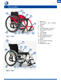 5
5
-
 6
6
-
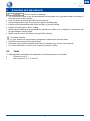 7
7
-
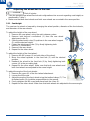 8
8
-
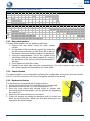 9
9
-
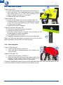 10
10
-
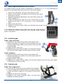 11
11
-
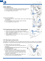 12
12
-
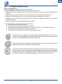 13
13
-
 14
14
-
 15
15
-
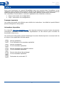 16
16
-
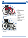 17
17
-
 18
18
-
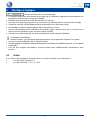 19
19
-
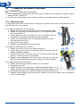 20
20
-
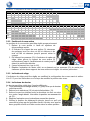 21
21
-
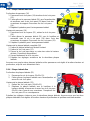 22
22
-
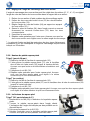 23
23
-
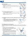 24
24
-
 25
25
-
 26
26
-
 27
27
-
 28
28
-
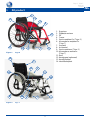 29
29
-
 30
30
-
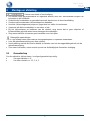 31
31
-
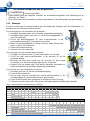 32
32
-
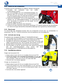 33
33
-
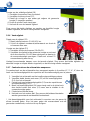 34
34
-
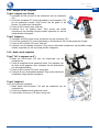 35
35
-
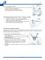 36
36
-
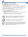 37
37
-
 38
38
-
 39
39
-
 40
40
-
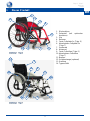 41
41
-
 42
42
-
 43
43
-
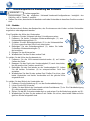 44
44
-
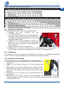 45
45
-
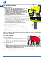 46
46
-
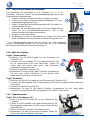 47
47
-
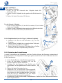 48
48
-
 49
49
-
 50
50
-
 51
51
-
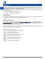 52
52
-
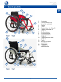 53
53
-
 54
54
-
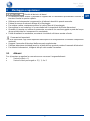 55
55
-
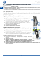 56
56
-
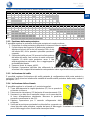 57
57
-
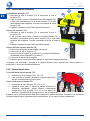 58
58
-
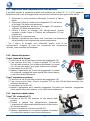 59
59
-
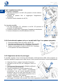 60
60
-
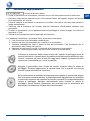 61
61
-
 62
62
-
 63
63
-
 64
64
-
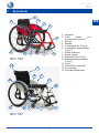 65
65
-
 66
66
-
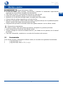 67
67
-
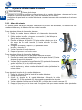 68
68
-
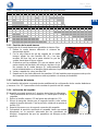 69
69
-
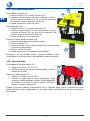 70
70
-
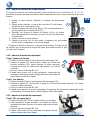 71
71
-
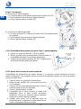 72
72
-
 73
73
-
 74
74
-
 75
75
-
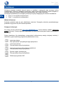 76
76
-
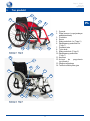 77
77
-
 78
78
-
 79
79
-
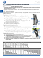 80
80
-
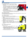 81
81
-
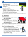 82
82
-
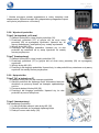 83
83
-
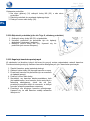 84
84
-
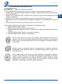 85
85
-
 86
86
-
 87
87
-
 88
88
-
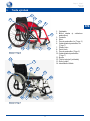 89
89
-
 90
90
-
 91
91
-
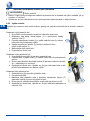 92
92
-
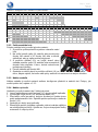 93
93
-
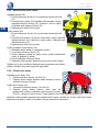 94
94
-
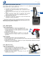 95
95
-
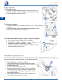 96
96
-
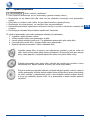 97
97
-
 98
98
-
 99
99
-
 100
100


Vermeiren Trigo Guía de instalación
- Tipo
- Guía de instalación
- Este manual también es adecuado para
en otros idiomas
- français: Vermeiren Trigo Guide d'installation
- italiano: Vermeiren Trigo Guida d'installazione
- English: Vermeiren Trigo Installation guide
- Deutsch: Vermeiren Trigo Installationsanleitung
- Nederlands: Vermeiren Trigo Installatie gids
- polski: Vermeiren Trigo Instrukcja instalacji
- čeština: Vermeiren Trigo instalační příručka
Artículos relacionados
-
Vermeiren Trigo T Guía de instalación
-
-
Vermeiren Trigo Manual de usuario
-
-
Vermeiren Sigma 230 Manual de usuario
-
-
Vermeiren Jazz S50 Manual de usuario
-
-
-
Vermeiren Bobby 24 Manual de usuario