GE PSB9120SFSS Guía de instalación
- Categoría
- Cocinas
- Tipo
- Guía de instalación
Este manual también es adecuado para

Installation
Instructions
Advantium
®
120V
Built-In SpeedCook
Ovens
PSB9120DF
PSB9120SF
ZSC1201
ZSC1202
49-40688-2
MFL59060909
08-13 GE
Español
For a Spanish version of this manual, visit
our Website at GEAppliances.com.
Para consultar una version en español de este
manual de instrucciones, visite nuestro sitio de
internet GEAppliances.com.

Safety Information
2
CONTENTS
Design Information
Models Available ......................................................................2
Product Dimensions and Clearances ............................4
Tools and Parts Required ....................................................4
Parts Supplied ...........................................................................4
Advance Planning ...................................................................4
Installation Preparation
Electrical Requirements .......................................................5
Preparing the Opening (Installation without
an accessory storage drawer) ................................. 6-9
Preparing the Opening (Installation with
an accessory storage drawer) ............................10-13
Installation Under a 36s Cooktop .................................13
Installation Instructions
Step 1, Remove Packaging and Parts ........................14
Step 2, Door Trim Removal for above 36”
Installation only ...................................................................15
Step 3, Slide the Oven into the Cutout .......................15
Step 4, Install Bottom Trim ..............................................16
Step 5, Install Bottom Trim with Accessory
Drawer ....................................................................................16
Step 6, Install Mounting Screws ....................................16
Step 7, Finalize Installation ..............................................16
BEFORE YOU BEGIN
Read these instructions completely and carefully.
IMPORTANT³ Save these instructions
for local inspector’s use.
IMPORTANT³ Observe all governing codes
and ordinances.
Note to Installer³ Be sure to leave these
instructions with the Consumer.
Note to Consumer³ Keep these instructions
with your Owner’s Manual for future reference.
Skill Level³ Installation of this appliance
requires basic mechanical and electrical skills.
Completion Time³ 1 Hour.
Proper installation is the responsibility
of the installer. Product failure due to improper
installation is not covered under the warranty. See
Owner’s Manual for warranty information.
NOTE: This oven is only approved to be installed
under the specific models as labeled on this unit.
IMPORTANT³ Use this oven only
for its intended purpose. Never use the oven
for warming or heating a room. Prolonged use
of the oven without proper ventilation can
be hazardous.
CAUTION:
For personal safety, remove house fuse or oven
circuit breaker before beginning installation
to avoid severe or fatal shock injury.
CAUTION:
For personal safety, the mounting surface
must be capable of supporting the cabinet load,
in addition to the added weight of the 80-pound
oven and 30-pound drawer, plus additional oven
loads of up to 50 pounds or a total weight of up
to 160 pounds.
CAUTION:
If installing the Advantium 120V Oven below 36s,
you must use the plastic bottom trim due to burn
risk to children. The plastic trim acts as insulation
and will help prevent burns to children from hot
surfaces.
CAUTION:
If installing the Advantium 120V Oven below 36s,
do not remove the plastic door trim due to burn
risk to children. The plastic trim acts as insulation
and will help prevent burns to children from hot
surfaces.
MODELS AVAILABLE
Profile Models:
PSB9120DFWW–White*
PSB9120DFBB–Black
PSB9120SFSS–Stainless Steel
Monogram Models:
ZSC1201SS–Stainless Steel
ZSC1202SS–Stainless Steel**
*No color-matched drawer available for this model.
** This unit cannot be installed with an accessory
storage drawer.

Información de seguridad
ANTES DE COMENZAR
Lea estas instrucciones por completo y con
detenimiento.
IMPORTANTE³ Guarde estas instrucciones
para el uso de inspectores locales.
IMPORTANTE³ Cumpla con todos los
códigos y ordenanzas vigentes.
Nota al instalador³ Asegúrese de dejar estas
instrucciones con el Consumidor.
Nota al consumidor³ Mantenga estas
instrucciones con el Manual del Propietario para
referencia futura.
Nivel de capacidad³ La instalación de este
aparato requiere capacidades mecánicas y eléctricas
básicas.
Tiempo de finalización³ 1 hora.
El instalador tiene la responsabilidad de efectuar una
instalación adecuada. La Garantía no cubre las fallas
del producto debido a una instalación incorrecta. Ver
el Manual del Propietario para información sobre la
garantía.
NOTA: Este horno sólo puede instalarse debajo
de los modelos específicos como se indica en la etiqueta
de esta unidad.
IMPORTANTE³ Utilice este horno sólo con
el objetivo para el que fue creado. Nunca use el
horno para entibiar o calentar una habitación. El uso
prolongado del horno sin una ventilación adecuada
puede resultar peligroso.
PRECAUCIÓN:
Para seguridad personal, quite el fusible o el interruptor
de circuitos de la vivienda antes de comenzar la
instalación a fin de evitar una lesión grave o fatal.
PRECAUCIÓN:
Para seguridad personal, la superficie de montaje debe
poder soportar la carga del gabinete, además de las 80
libras del horno y las 30 libras del cajón, más las cargas
adicionales del horno de hasta 50 libras o un peso total
de hasta 160 libras.
PRECAUCIÓN:
Si va a instalar el horno Advantium de 120V debajo
de 36”, usted debe utilizar el reborde inferior plástico
debido al riesgo de quemaduras para los niños.
El reborde plástico actúa como aislante y evitará
que los niños sufran quemaduras provocadas
por las superficies calientes.
PRECAUCIÓN:
Si va a instalar el horno Advantium de 120V debajo
de 36”, usted no debe quitar el reborde plástico de
la puerta debido al riesgo de quemaduras para los
niños. El reborde plástico actúa como aislante y evitará
que los niños sufran quemaduras provocadas por las
superficies calientes.
3

Design Information
4
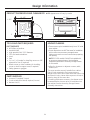
PRODUCT DIMENSIONS AND CLEARANCES NOTE: Appearance will vary by model.
TOOLS AND PARTS REQUIRED
(NOT SUPPLIED)
#2 Phillips screwdriver
Hand-held drill
High speed drill bit, 3/32s diameter
3/8s slot-head screwdriver
Level
Saw
2 x 4 or 2 x 2 lumber for installing runners or 3/8s
plywood for floor (if required)
Wood screws or other hardware for installing
runner or shelf to support oven (if required)
Safety glasses or goggles
PARTS SUPPLIED
6 screws (3 required, 3 extra)
5 color-matched screws (4 required, 1 extra)
Bottom trim (2)
ADVANCE PLANNING
These ovens may be installed directly into a 30s wide
oven cabinet.
Cutout dimensions are NOT the same for installation
with or without an accessory storage drawer.
Make sure to use the correct cutout when preparing
the opening.
NOTE: ZSC1202 models CANNOT be installed with
an accessory storage drawer. See Installation
Preparation Without an Accessory Storage Drawer
for this model.
$OORZIRUFOHDUDQFHWRDGMDFHQWFRUQHUVZDOOV
drawers, etc.
The oven must be securely installed in a cabinet
that is firmly attached to the house structure.
Weight on the oven door could cause the oven to tip
and result in injury. Never allow anyone to climb, sit,
stand or hang on the oven door.
If installing the drawer accessory, the drawer must
be assembled to the oven prior to installation into
the cabinet. See the Accessory Storage Drawer
Assembly Instructions.
21-1/2s
1s
13s
19s
29-3/4s
1-3/5s
1-1/10s

Installation Preparation
5
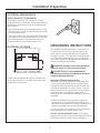
ELECTRICAL REQUIREMENTS
Single Advantium 120 Installation:
This product requires a 120-volt, 60 Hz, 15-amp
circuit and draws 1.8 kilowatts. This product must be
connected to a supply circuit of the proper voltage
and frequency.
:LUHVL]HPXVWFRQIRUPWRWKHUHTXLUHPHQWVRIWKH
National Electrical Code or the prevailing local code
for this kilowatt rating.
7KHSRZHUVXSSO\FRUGDQGSOXJVKRXOGEHEURXJKW
to a separate 15 or 20 ampere branch circuit single
grounded receptacle. The outlet box should be
located within reach of the 48” power cord.
ELECTRICAL LOCATION
GROUNDING INSTRUCTIONS
This appliance must be grounded. In the event of
an electrical short circuit, grounding reduces the
risk of electric shock by providing an escape wire
for electric current. This appliance is equipped with
a cord having a grounding wire with a grounding
plug. The plug must be plugged into an outlet that is
properly installed and grounded.
WARNING: Improper use of the grounding
plug can result in a risk of electric shock.
¡ADVERTENCIA!: El uso inadecuado del
enchufe de conexión a tierra puede provocar un
riesgo de descarga eléctrica.
Important: (Please read carefully).
The power cord of this appliance is equipped with
a three-prong (grounding) plug that mates with a
standard three-prong grounding wall receptacle to
minimize the possibility of electric shock. Consult a
qualified electrician or serviceman if the grounding
instructions are not completely understood, or if
doubt exists as to whether the appliance is properly
grounded.
:KHUHDVWDQGDUGWZRSURQJZDOOUHFHSWDFOHLV
encountered, it is the personal responsibility and
obligation of the consumer to have it replaced with a
properly grounded three-prong wall receptacle.
Do not, under any circumstances, cut or remove the
third (ground) prong from the power cord.
DO NOT USE AN EXTENSION CORD. If the power
supply cord is too short, have a qualified electrician or
serviceman install an outlet near the appliance.
Install a recessed electrical outlet in the back wall
of the opening within 6s of either side and at least
9s above the cutout floor.
Locate outlet box in the shaded area
6”
9”

6
Installation Preparation
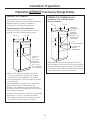
Preparation WITHOUT an Accessory Storage Drawer
PREPARE THE OPENING (cont.)
Installation over a GE/Monogram
Warming Drawer:
NOTE: Additional clearances between the cutouts
may be required. Check to be sure the oven supports
above the Warming Drawer location do not obstruct
the required interior depth and height. See Warming
Drawer installation instructions for details.
30s
23-1/2s
25-1/4s
17-1/2s
2s Min.
(3
s Recommended)
Per Warming
Drawer
Requirement
Construct
Solid Bottom
Min. 3/8s
Plywood
Supported
by 2 x 4 or 2 x
2 Runners all
Four Sides
PREPARE THE OPENING
The Advantium 120V can be installed in
combination with other GE/Monogram appliances.
Always follow each product’s Installation
Instructions to complete the installation.
Single Advantium 120V Installation:
Order a 30s wide single oven cabinet or cut the
opening in a wall to the dimensions shown.
$OORZs case trim overlap on the sides,
1-1/16s overlap on the top and 7/8s overlap
on the bottom of the opening for all models.
2YHQRYHUODSVZLOOFRQFHDOFXWHGJHVRQDOOVLGHV
of the opening.
When installed over a single oven or a warming
drawer, allow at least 2s between the two
openings. This separation will provide clearance
for bottom overlap of the Advantium 120V and the
other appliance overlaps.
Construct a solid oven floor of 3/8s min. thick plywood
supported by 2 x 4 or 2 x 2 runners on all sides.
7KHVXSSRUWPXVWEHOHYHODQGULJLGO\PRXQWHG
flush with the bottom edge of the cutout.
30s
23-1/2s
25-1/4s
17-1/2s
Construct
Base
Min. 3/8s
Plywood
Supported
by 2 x 4 or
2 x 2 Runners
all Four Sides

Installation Preparation
7
Preparation WITHOUT an Accessory Storage Drawer
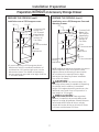
PREPARE THE OPENING (cont.)
Installation over a GE/Monogram Oven and
Warming Drawer:
NOTE: Additional clearances between the cutouts
may be required. Check to be sure the oven
supports above the Warming Drawer location
do not obstruct the required interior depth
and height. See Warming Drawer installation
instructions for details.
CAUTION: For personal safety, the
mounting surface must be capable of supporting
the cabinet load, in addition to the added
weight of this approximate 80-pound oven, plus
additional oven loads of up to 50 pounds or a
total weight of 130 pounds.
PRECAUCIÓN: Para seguridad
personal, la superficie de montaje debe poder
soportar la carga del gabinete, además del peso
aproximado de 80 libras del horno, más las
cargas adicionales del horno de hasta 50 libras
o un peso total de hasta 130 libras.
Construct Solid
Bottom Min.
3/8s Plywood
Supported by
2 x 4 or 2 x 2
Runners all
Four Sides
30s
23-1/2s
25-1/4s
17-1/2s
2s Min.
(3
s Recommended)
Per Oven
Requirement
2s Min.
(3
s Recommended)
PREPARE THE OPENING (cont.)
Installation over a GE/Monogram oven:
,I\RXDUHUHSODFLQJD*(0RQRJUDPHOHFWULF
double oven with the combined installation of
an Advantium 120V and a single oven, use the
dimensions shown. The middle rail separating
the two openings may need to be larger than the
2s minimum shown.
30s
23-1/2s
25-1/4s
17-1/2s
2s Min.
(3
s Recommended)
Construct Solid
Bottom Min.
3/8s Plywood
Supported by
2 x 4 or 2 x 2
Runners all
Four Sides
Per Oven
Requirement
Per Warming
Drawer
Requirement

8
Installation Preparation
Preparation WITHOUT an Accessory Storage Drawer
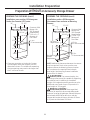
PREPARE THE OPENING (cont.)
Installation under a GE/Monogram
Microwave Oven and over a Warming
Drawer:
NOTE: Additional clearances between the cutouts
may be required. Check to be sure the oven
supports above the Warming Drawer location
do not obstruct the required interior depth
and height. See Warming Drawer installation
instructions for details.
CAUTION: For personal safety, the
mounting surface must be capable of supporting
the cabinet load, in addition to the added
weight of this approximate 80-pound oven, plus
additional oven loads of up to 50 pounds or a
total weight of 130 pounds.
PRECAUCIÓN: Para seguridad
personal, la superficie de montaje debe poder
soportar la carga del gabinete, además del peso
aproximado de 80 libras del horno, más las
cargas adicionales del horno de hasta 50 libras
o un peso total de hasta 130 libras.
Construct Solid
Bottom Min.
3/8s Plywood
Supported by
2 x 4 or 2 x 2
Runners all
Four Sides
30s
23-1/2s
25-1/4s
17-1/2s
2s Min.
(3s Recommended)
Per Oven
Requirement
3.5s Min.
(4.5
s Recommended)
PREPARE THE OPENING (cont.)
Installation over another GE/Monogram
Under-the-Counter (UTC) oven:
,I\RXDUHPRXQWLQJDQ8QGHUWKH&RXQWHU
GE/Monogram oven over another, use the
dimensions shown. The middle rail separating
the two openings may need to be larger than
the 2s minimum shown.
30s
23-1/2s
25-1/4s
17-1/2s
2s Min.
(3
s Recommended)
Construct Solid
Bottom Min.
3/8s Plywood
Supported by
2 x 4 or 2 x 2
Runners all
Four Sides
17-1/2s
Per Warming
Drawer
Requirement

PREPARE THE OPENING (cont.)
Installation beside another GE/Monogram
Built-in Speedcook Oven:
,I\RXDUHPRXQWLQJRQH8QGHUWKH&RXQWHU
GE/Monogram oven beside the other, use the
dimensions shown. The middle rail separating
the two openings may need to be larger than
the 4-1/2s minimum shown.
25-1/4s
17-1/2s
Installation Preparation
9
Preparation WITHOUT an Accessory Storage Drawer
Cooktop
Cooktop
25s
1-1/2s Min.
4s High
Toekick
23-1/2
s
25-1/4
s
17-1/2
s
36
s
Countertop
Height
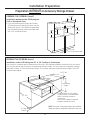
NOTE: The oven is only approved to be installed
under the specific models as labeled on the unit.
23-1/2s
17-1/2s
4-1/2s Min.
(5-1/2s Recommended)
PREPARE THE OPENING (cont.)
Installation under a GE/Monogram 30s or 36s Cooktop or Countertop:
Gas or electric cooktops may be installed over this oven. See cooktop installation instructions for the cutout
size. See the label on top of the oven for approved cooktop models. This oven requires a separate, properly
grounded 15-Amp, 120-Volt, 60Hz power supply. The cooktop requires a separate power supply. Use a 36s
or wider base cabinet.
Cooktop height including depth
of electrical box on some models.
Refer to cooktop installation
instructions.
No minimum clearance required
between cooktop and oven.
25-1/4s

10
Installation Preparation
Preparation WITH an Accessory Storage Drawer
NOTE: MODEL ZSC1201 CAN ONLY BE INSTALLED WITH AN ACCESSORY STORAGE DRAWER IF INSTALLED ABOVE 36-3/4
s
.
MODEL ZSC1202 CANNOT BE INSTALLED WITH AN ACCESSORY STORAGE DRAWER. SEE INSTALLATION PREPARATION WITHOUT
AN ACCESSORY STORAGE DRAWER FOR THIS MODEL.
Installation over a GE/Monogram
Warming Drawer:
NOTE: Additional clearances between the cutouts
may be required. Check to be sure the oven
supports above the Warming Drawer location
do not obstruct the required interior depth
and height. See Warming Drawer installation
instructions for details.
30s
23-1/2s
25-1/4s
Min.
21s
2s Min.
(3
s Recommended)
Per Warming
Drawer
Requirement
Construct Solid
Bottom Min. 3/8s
Plywood Supported
by 2 x 4 or 2 x 2
Runners all Four
Sides
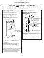
PREPARE THE OPENING (cont.)
The Advantium 120V can be installed in
combination with other GE/Monogram appliances.
Always follow each product’s Installation
Instructions to complete the installation.
Single Advantium 120V Installation:
Order a 30s wide single oven cabinet or cut
the opening in a wall to the dimensions shown.
$OORZs case trim overlap on the sides,
1-1/16s overlap on the top and 7/8s overlap
on the bottom of the opening for all models.
2YHQRYHUODSVZLOOFRQFHDOFXWHGJHVRQDOOVLGHV
of the opening.
When installed over a single oven or a warming
drawer, allow at least 2s between the two
openings. This separation will provide clearance
for bottom overlap of the Advantium 120V and the
other appliance overlaps.
Construct a solid oven floor of 3/8s min. thick plywood
supported by 2 x 4 or 2 x 2 runners on all sides.
7KHVXSSRUWPXVWEHOHYHODQGULJLGO\PRXQWHG
flush with the bottom edge of the cutout.
30s
23-1/2s
25-1/4s
Min.
21s
Construct Base
Min. 3/8s Plywood
Supported by 2 x
4 or 2 x 2 Runners
all Four Sides
PREPARE THE OPENING (cont.)
36-3/4s
Min.*
* Required for
Monogram models
* Required for
Monogram models
36-3/4s
Min.*

11
Installation Preparation
Preparation WITH an Accessory Storage Drawer
NOTE: MODEL ZSC1201 CAN ONLY BE INSTALLED WITH AN ACCESSORY STORAGE DRAWER IF INSTALLED ABOVE 36-3/4
s
.
MODEL ZSC1202 CANNOT BE INSTALLED WITH AN ACCESSORY STORAGE DRAWER. SEE INSTALLATION PREPARATION WITHOUT
AN ACCESSORY STORAGE DRAWER FOR THIS MODEL.
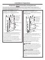
PREPARE THE OPENING (cont.)
Installation over a GE/Monogram Oven and
Warming Drawer:
* For existing cutouts, a maximum width of 28-1/2s
is acceptable. If the opening is slightly wider,
secure a furring strip on each side of the cutout
for securing the oven.
NOTE: Additional clearances between the cutouts
may be required. Check to be sure the oven
supports above the Warming Drawer location
do not obstruct the required interior depth
and height. See Warming Drawer installation
instructions for details.
CAUTION: For personal safety, the
mounting surface must be capable of supporting
the cabinet load, in addition to the added weight
of this approximate 80-pound oven and 30-pound
drawer, plus additional oven loads of up to 50
pounds or a total weight of 160 pounds.
PRECAUCIÓN: Para seguridad
personal, la superficie de montaje debe poder
soportar la carga del gabinete, además del peso
aproximado de 80 libras del horno y las 30 libras
del cajón, más las cargas adicionales del horno
de hasta 50 libras o un peso total de hasta
160 libras.
Construct Solid
Bottom Min.
3/8s Plywood
Supported by
2 x 4 or 2 x 2
Runners all
Four Sides
30s
23-1/2s
21s
2s Min.
(3
s Recommended)
Per Oven
Requirement
2s Min.
(3
s Recommended)
PREPARE THE OPENING (cont.)
Installation over a GE/Monogram Oven:
* For existing cutouts, a maximum width of 28-1/2s
is acceptable. If the opening is slightly wider,
secure a furring strip on each side of the cutout
for securing the oven.
,I\RXDUHUHSODFLQJD*(0RQRJUDPHOHFWULF
double oven with the combined installation
of an Advantium 120V and a single oven, use
the dimensions shown. The middle rail separating
the two openings may need to be larger than
the 2s minimum shown.
30s
23-1/2s
25-1/4s
Min.*
21s
2s Min.
(3
s Recommended)
Construct Solid
Bottom Min.
3/8s Plywood
Supported by
2 x 4 or 2 x 2
Runners all
Four Sides
Per Oven
Requirement
25-1/4s
Min.*
* Required for
Monogram models
45-1/4s
36-3/4s
Min.
45-1/4s
Recommended*
Per Warming
Drawer Requirement

12
Installation Preparation
Preparation WITH an Accessory Storage Drawer
NOTE: MODEL ZSC1201 CAN ONLY BE INSTALLED WITH AN ACCESSORY STORAGE DRAWER IF INSTALLED ABOVE 36-3/4
s
.
MODEL ZSC1202 CANNOT BE INSTALLED WITH AN ACCESSORY STORAGE DRAWER. SEE INSTALLATION PREPARATION WITHOUT
AN ACCESSORY STORAGE DRAWER FOR THIS MODEL.
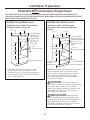
PREPARE THE OPENING (cont.)
Installation under a GE/Monogram
Microwave Oven and over a Warming
Drawer:
NOTE: Additional clearances between the cutouts
may be required. Check to be sure the oven
supports above the Warming Drawer location
do not obstruct the required interior depth
and height. See Warming Drawer installation
instructions for details.
CAUTION: For personal safety, the
mounting surface must be capable of supporting
the cabinet load, in addition to the added
weight of this approximate 80-pound oven, plus
additional oven loads of up to 50 pounds or a
total weight of 130 pounds.
PRECAUCIÓN: Para seguridad
personal, la superficie de montaje debe poder
soportar la carga del gabinete, además del peso
aproximado de 80 libras del horno, más las
cargas adicionales del horno de hasta 50 libras
o un peso total de hasta 130 libras.
Construct Solid
Bottom Min. 3/8s
Plywood Supported
by 2 x 4 or 2 x 2
Runners all Four
Sides
30s
23-1/2s
25-1/4s
3.5s Min.
(4.5
s Recommended)
PREPARE THE OPENING (cont.)
Installation over another GE/Monogram
Under-the-Counter (UTC) oven:
,I\RXDUHPRXQWLQJDQ8QGHUWKH&RXQWHU
GE/Monogram oven over another, use the
dimensions shown. The middle rail separating
the two openings may need to be larger than
the 2s minimum shown.
30s
23-1/2s
25-1/4s
21s
2s Min.
(3
s Recommended)
Construct Solid
Bottom Min.
3/8s Plywood
Supported by
2 x 4 or 2 x 2
Runners all
Four Sides
21s*
2s Min.
(3
s Recommended)
21s*
Per Oven
Requirement
Per Warming
Drawer
Requirement
* PSB9120 model only
*PSB9120 model only

PREPARE THE OPENING (cont.)
Installation under a GE Profile 30s or 36s Cooktop or Countertop:
Gas or electric cooktops may be installed
over this oven. See cooktop installation
instructions for the cutout size. See the
label on top of the oven for approved
cooktop models. This oven requires
a separate, properly
grounded 15-Amp,
120-Volt, 60Hz power
supply. The cooktop
requires a separate power
supply. Use a 36s or wider
base cabinet.
IMPORTANT:
For Profile models only.
IMPORTANT:
For PSB9120 model only.
The Monogram oven
and drawer combination
cannot be installed below
a countertop.
13
Installation Preparation
Cooktop
Cooktop
25s
1-1/2s Min.
4s High
Toekick
23-1/2
s
25-1/4
s
21
s
36
s
Countertop
Height
PREPARE THE OPENING (cont.)
Installation beside another GE/Monogram
Built-in Speedcook Oven:
,I\RXDUHPRXQWLQJRQH8QGHUWKH&RXQWHU*(
Monogram oven beside the other, use
the dimensions shown. The middle rail separating
the two openings may need to be larger than
the 4-1/2s minimum shown.
25-1/4s
21s
Preparation WITH an Accessory Storage Drawer
NOTE: MODEL ZSC1201 CAN ONLY BE INSTALLED WITH AN ACCESSORY STORAGE DRAWER IF INSTALLED ABOVE 36-3/4
s
.
MODEL ZSC1202 CANNOT BE INSTALLED WITH AN ACCESSORY STORAGE DRAWER. SEE INSTALLATION PREPARATION WITHOUT
AN ACCESSORY STORAGE DRAWER FOR THIS MODEL.
NOTE: The oven is only approved to be installed
under the specific models as labeled on the unit.
23-1/2s
21s
4-1/2s Min.
(5-1/2
s Recommended)
25-1/4s
Cooktop height including
depth of electrical box on
some models. Refer to cooktop
installation instructions.
No minimum clearance
required between cooktop and
oven.

1
REMOVE THE PACKAGING AND PARTS
14
Installation Instructions
5HPRYHDOOSDFNLQJPDWHULDODQGWDSH
/RFDWHSDUWVSDFNDJHFRQWDLQLQJPRXQWLQJVFUHZV
5HPRYHWKHRYHQIURPWKHFDUWRQ'RQRWOLIWXQLW
by handle or conduit. Two people are required to lift
this oven.
2SHQWKHGRRUDQGUHPRYHDQ\SDFNDJLQJLQRYHQ
Owner’s
Manual
Owner’s Manual
Installation
Instructions
Glass Tray
Metal Trays (2)
Turntable Ring
Bottom Trim – Plastic
6 Brass Screws
(3 required, 3 extra)
IMPORTANT: If installing the Advantium 120V Oven
with an accessory storage drawer, read the storage
drawer assembly instructions to assemble the
products together before proceeding to Step 2.
CAUTION: If installing the Advantium
120V Oven below 36s, you must use the plastic
bottom trim due to burn risk to children. The
plastic trim acts as insulation and will help prevent
burns to children from hot surfaces.
Cook Book
5 Color-Matched Screws
(4 required, 1 extra)
Cooking Guide
Cooking
Guide
Bottom Trim – Metal
Rack
PRECAUCIÓN: Si va a instalar el
horno Advantium de 120V debajo de 36”, usted
debe utilizar el reborde inferior plástico debido al
riesgo de quemaduras para los niños. El reborde
plástico actúa como aislante y evitará que los
niños sufran quemaduras provocadas por las
superficies calientes.

Installation Instructions
15
3
SLIDE THE OVEN INTO THE CUTOUT
CAUTION: Two people are required to
lift the oven into the opening. Grasp the bottom
at front and rear. DO NOT USE THE HANDLE TO LIFT
THE OVEN. DAMAGE WILL OCCUR.
PRECAUCIÓN: Se necesitan dos
personas para levantar el horno hasta la abertura.
Tómelo de la parte inferior desde el frente y la parte
trasera. NO USE LA MANIJA PARA LEVANTAR EL
+25126(352'8&,5È1'$³26.
/LIWDQGKROGWKHRYHQDWWKHIURQWRIWKHRSHQLQJ
Hold the oven at an angle and plug in the power
cord.
&DUHIXOO\VOLGHWKHRYHQLQWRWKHFDELQHWSDUW
way. Leave the oven a few inches forward of
the cabinet frame.
&KHFNWREHVXUHWKHSRZHUFRUGLVQRWWUDSSHG
under the oven or along the sides of the oven.
2
DOOR TRIM REMOVAL FOR ABOVE
36sINSTALLATION ONLY
If installing the Advantium 120V Oven above 36s
from the floor, you may remove the plastic trim
from the bottom of the door for esthetic purposes
if desired.
If installing above 36s, remove the 3 screws that
secure the plastic trim to the bottom of the door.
Discard plastic trim. Replace screws.
CAUTION: If installing the Advantium
120V Oven below 36s, do not remove the
plastic door trim due to burn risk to children.
The plastic trim acts as insulation and will help
prevent burns to children from hot surfaces.
PRECAUCIÓN: Si va a instalar el
horno Advantium de 120V debajo de 36”, usted
no debe quitar el reborde plástico de la puerta
debido al riesgo de quemaduras para los
niños. El reborde plástico actúa como aislante
y evitará que los niños sufran quemaduras
provocadas por las superficies calientes.

16
Installation Instructions
6
INSTALL MOUNTING SCREWS
Slide the oven the remaining way into the opening
so that the side flanges and control panel are
against the cabinet frame. Make sure that the oven
is centered in the opening.
Open the door, place a turntable tray in the oven
and make sure that the tray in the unit is level.
Drill pilot holes through the side flanges.
Drive the color-matched screws into the side
flanges. It is recommended that the screws
be hand tightened.
If installing oven with an accessory storage
drawer:
Open the drawer.
Drill pilot holes through the side flanges.
Drive color-matched screws into the side flanges.
It is recommended that the screws be hand
tightened.
NOTE: If installing the Profile Advantium 120V Oven
with an accessory storage drawer, you must use
the Under-the-Counter (UTC) mounting bracket for
the drawer.
If installing the Monogram Advantium integrated
model ZSC1201 above 36s, the UTC mounting bracket
for the accessory storage drawer must be used.
7 FINALIZE INSTALLATION
Turn power on at the source. The interior light
should come on when the door is opened.
Refer to Owner’s Manual for operating instructions.
4
INSTALL BOTTOM TRIM
CAUTION: If installing the Advantium
120V Oven below 36s, you must use the plastic
bottom trim due to burn risk to children. The plastic
trim acts as insulation and will help prevent burns
to children from hot surfaces.
PRECAUCIÓN: Si va a instalar el horno
Advantium de 120V debajo de 36”, usted debe utilizar
el reborde inferior plástico debido al riesgo de
quemaduras para los niños. El reborde plástico
actúa como aislante y evitará que los niños sufran
quemaduras provocadas por las superficies calientes.
NOTE: If installing the Advantium 120V Oven
with an accessory storage drawer, the bottom trim
is not required. Proceed to Step 5.
Installation Below 36s, align trim tabs on the plastic
trim to slots in the bottom of the oven.
Installation Above 36s, align trim tabs on the plastic
or metal trim to slots in the bottom of the oven.
Secure the bottom trim to the bottom of the oven
using 3 screws provided.
5
INSTALL BOTTOM TRIM WITH
ACCESSORY DRAWER
If installing with an accessory drawer, see
installation instructions on page 17 or instructions
that come with the accessory drawer.
Metal
Trim
Plastic
Trim OR
Plastic
Trim

17
GE Consumer & Industrial Appliances
Assembly Instructions
Advantium
®
Built-In Accessory Storage Drawer
JX2200, JX2201, ZX2201
NOTE: Appearance will vary by model.
BEFORE YOU BEGIN
Read these instructions completely and carefully.
Read the Installation Instructions for the Advantium
120V or 240V oven completely and carefully for cutout
dimensions and step-by-step instructions.
IMPORTANT³ Save these instructions for
local inspector’s use.
IMPORTANT³ Observe all governing codes
and ordinances.
NOTE TO INSTALLER: Be sure to leave these
instructions with the Consumer.
NOTE TO CONSUMER: Keep these instructions with
your Advantium 120V or 240V Oven Owner’s Manual
for future reference.
SKILL LEVEL: Installation of this appliance requires
basic mechanical skills.
COMPLETION TIME: One hour with the installation
of an Advantium 120V or 240V oven.
Proper installation is the responsibility of the installer.
Product failure due to improper installation is not
covered under the Warranty. See the Advantium
120V or 240V Oven Owner’s Manual for warranty
information.
TOOLS REQUIRED
3KLOOLSVVFUHZGULYHU
PARTS SUPPLIED
6LGH6XSSRUWV
6FUHZV
6FUHZVFRORUPDWFKHG
8QGHUWKH&RXQWHU0RXQWLQJ%UDFNHW
MODELS AVAILABLE
Profile Models:
JX2200BB–Black
JX2201SS–Stainless Steel
Monogram Models:
ZX2201SS–Stainless Steel (for installation above 36s only)
NOTE: Advantium 240V model ZSC2202SS and
Advantium 120V model ZSC1202 CANNOT be
installed with an accessory storage drawer. See
Installation Preparation Without an Accessory Storage
Drawer in the Installation Instructions for these models.
PRODUCT DIMENSIONS AND CLEARANCES
Allow 15s clearance
when fully open
5s

2
UNDER-THE-COUNTER (UTC)
MOUNTING BRACKET INSTALLATION
NOTE: For UTC models PSB9120 and ZSC1201 only.
A
Open the accessory drawer so you have
access to the top bracket.
B
Remove the three screws securing the top
bracket.
C
Install the new UTC mounting bracket using
the screws removed previously.
D
Close the drawer and proceed with the
installation.
1
REMOVE PACKAGING AND PARTS
5HPRYHWKHGUDZHUIURPWKHFDUWRQ
5HPRYHDOOSDFNLQJPDWHULDODQGWDSH
2SHQWKHGUDZHUDQGUHPRYHDQ\SDUWVLQVLGH
/RFDWHSDUWV
ASSEMBLY TO ADVANTIUM BUILT-IN SPEEDCOOK OVEN
Assembly Instructions
Side Supports (2)
3
ASSEMBLING THE OVEN TO DRAWER
A
Place storage drawer on a surface with
the front of drawer hanging over the edge
of the surface. Not placing the front edge
of drawer over the edge of the surface may
result in damage to the drawer since the front
edge of drawer hangs below the bottom
of drawer.
B
Place the oven on top of the storage drawer.
Make sure that the back and sides of the oven
align with the back and sides of drawer.
NOTE: The bottom of the oven side flanges will
sit directly in front of the top of the storage
drawer side flanges.
18
Under-the-Counter
(UTC) Mounting Bracket
Color-Matched
Screws
(4 required,
1 extra)
Screws
(6 required,
2 extra)

19
ASSEMBLING THE OVEN TO DRAWER
(cont.)
C
Remove the front two bottom screws on each
side of the oven and the top center screw on
each side of the storage drawer.
D
Place the side supports into the tabs on the
drawer and secure using the screws supplied
and the screws removed in Step C.
E
The oven and storage drawer assembly is now
ready to be installed. Return to the Advantium
120V or 240V Built-In SpeedCook Oven
Installation Instructions to complete
the installation.
Side
Support
120v only
ASSEMBLY TO ADVANTIUM BUILT-IN SPEEDCOOK OVEN

Printed in Korea
NOTE: While performing installations described in this book,
safety glasses or goggles should be worn.
NOTE: Product improvement is a continuing endeavor at
General Electric. Therefore, materials, appearance and
specifications are subject to change without notice.
GE Appliances & Lighting
Appliances
General Electric Company
Louisville, KY 40225
GEAppliances.com

Instrucciones
de instalación
Hornos de cocción
rápida empotrados
de 120V Advantium
®
PSB9120DF
PSB9120SF
ZSC1201
ZSC1202
49-40688-1
MFL59060909
07-13 GE

Información de seguridad
2
CONTENIDOS
Información de diseño
Modelos disponibles ..............................................................2
Dimensiones y distancias del producto .......................3
Herramientas y piezas requeridas ..................................3
Piezas provistas .......................................................................3
Planificación previa ................................................................3
Preparación para la instalación
Requisitos eléctricos ..............................................................4
Preparación de la abertura (instalación sin un
cajón de almacenamiento de accesorios) .........5-8
Preparación de la abertura (instalación con un
cajón de almacenamiento de accesorios) .......9-12
Instalación bajo una estufa de 36”..............................12
Instrucciones de instalación
Paso 1, Quite el empaque y las piezas ......................13
Paso 2, Remoción del Reborde de la Puerta
Sólo para Instalaciones sobre 36” .............................14
Paso 3, Deslice el Horno Dentro de la Abertura ....14
Paso 4, Instale el reborde inferior ................................15
Paso 5, Instale el Reborde Inferior con el
Canjón de Accesorios ......................................................15
Paso 6, Instale los tornillos de montaje .....................15
Paso 7, Finalice la instalación ........................................15
ANTES DE COMENZAR
Lea estas instrucciones por completo y con
detenimiento.
IMPORTANTE³ Guarde estas instrucciones
para el uso de inspectores locales.
IMPORTANTE³ Cumpla con todos los
códigos y ordenanzas vigentes.
Nota al instalador³ Asegúrese de dejar estas
instrucciones con el Consumidor.
Nota al consumidor³ Mantenga estas
instrucciones con el Manual del Propietario para
referencia futura.
Nivel de capacidad³ La instalación de este
aparato requiere capacidades mecánicas y eléctricas
básicas.
Tiempo de finalización³ 1 hora.
El instalador tiene la responsabilidad de efectuar una
instalación adecuada. La Garantía no cubre las fallas
del producto debido a una instalación incorrecta. Ver
el Manual del Propietario para información sobre la
garantía.
NOTA: Este horno sólo puede instalarse debajo
de los modelos específicos como se indica en la etiqueta
de esta unidad.
IMPORTANTE³ Utilice este horno sólo con
el objetivo para el que fue creado. Nunca use el
horno para entibiar o calentar una habitación. El uso
prolongado del horno sin una ventilación adecuada
puede resultar peligroso.
PRECAUCIÓN:
Para seguridad personal, quite el fusible o el interruptor
de circuitos de la vivienda antes de comenzar la
instalación a fin de evitar una lesión grave o fatal.
PRECAUCIÓN:
Para seguridad personal, la superficie de montaje debe
poder soportar la carga del gabinete, además de las 80
libras del horno y las 30 libras del cajón, más las cargas
adicionales del horno de hasta 50 libras o un peso total
de hasta 160 libras.
PRECAUCIÓN:
Si va a instalar el horno Advantium de 120V debajo
de 36”, usted debe utilizar el reborde inferior plástico
debido al riesgo de quemaduras para los niños.
El reborde plástico actúa como aislante y evitará
que los niños sufran quemaduras provocadas
por las superficies calientes.
PRECAUCIÓN:
Si va a instalar el horno Advantium de 120V debajo
de 36”, usted no debe quitar el reborde plástico de
la puerta debido al riesgo de quemaduras para los
niños. El reborde plástico actúa como aislante y evitará
que los niños sufran quemaduras provocadas por las
superficies calientes.
MODELOS DISPONIBLES
Modelos Profile:
PSB9120DFWW–Blanco*
PSB9120DFBB–Negro
PSB9120SFSS–Acero inoxidable
Modelos Monogram:
ZSC1201SS–Acero inoxidable
ZSC1202SS–Acero inoxidable**
*
Para este modelo no hay cajón del mismo color
disponible.
** Esta unidad no puede instalarse con un cajón
de almacenamiento de accesorios.

Información de diseño
3
DIMENSIONES Y DISTANCIAS DEL PRODUCTO NOTA: La apariencia varía según el modelo.
HERRAMIENTAS Y PIEZAS REQUERIDAS
(NO PROVISTAS)
Destornillador de estrella #2
Perforadora de mano
Broca para perforadora de alta velocidad
de 3/32” de diámetro
Destornillador para cabeza ranurada de 3/8”
Nivel
Sierra
Madera de 2 x 4 o 2 x 2 para instalar guías
o madera terciada de 3/8” para el piso (si se
requiriera)
Tornillos para madera u otro elemento para
instalar guías o estante para sostener el horno
(si se requiriera)
Gafas o lentes de seguridad
PIEZAS PROVISTAS
6 tornillos (3 necesarios, 3 extra)
5 tornillos de color (4 requeridos, 1 extra)
Reborde inferior (2)
PLANIFICACIÓN PREVIA
Estos hornos pueden instalarse directamente dentro
de un gabinete para horno de 30” de ancho.
Las dimensiones del recorte NO son iguales para la
instalación con o sin un cajón de almacenamiento
para accesorios.
Asegúrese de utilizar el recorte correcto cuando
prepare la abertura
NOTA: Los modelos ZSC1202 NO PUEDEN instalarse
con un cajón de almacenamiento para accesorios.
Para este modelo, ver Preparación para instalación
sin un cajón de almacenamiento para accesorios.
'HMHXQDGLVWDQFLDUHVSHFWRGHULQFRQHVSDUHGHV
cajones adyacentes, etc.
El horno debe instalarse bien en un gabinete que
se encuentre firmemente sujeto a la estructura de
la casa. Si se coloca peso sobre la puerta del horno,
éste puede volcarse y provocar lesiones. Nunca
permita que nadie se suba, siente, pare o cuelgue
de la puerta del horno.
Si va a instalar el accesorio del cajón, éste debe
montarse en el horno antes de la instalación en
el gabinete. Ver las Instrucciones de montaje del
cajón de almacenamiento de accesorios.
21-1/2”
1”
13”
19”
29-3/4”
1-3/5”
1-1/10”

Preparación para la instalación
4
REQUISITOS ELÉCTRICOS
Instalación de Advantium de 120V único:
Este producto requiere un circuito de 120 voltios,
60 hercios, 15 amperios y consume 1.8 kilovatios. Este
producto debe conectarse a un circuito de suministro
del voltaje y frecuencia adecuados.
(OWDPDxRGHOFDEOHGHEHFXPSOLUFRQORVUHTXLVLWRV
del Código Eléctrico Nacional o con el código local
vigente para esta clasificación de kilovatios.
(OFDEOH\HQFKXIHGHVXPLQLVWURHOpFWULFRGHEH
llevarse a un receptáculo separado único de circuito
derivado con conexión a tierra de 15 o 20 amperios.
La caja de distribución debe ubicarse dentro del
alcance del cable eléctrico de 48”.
UBICACIÓN DE LA ELECTRICIDAD
INSTRUCCIONES DE
CONEXIÓN A TIERRA
Este electrodoméstico deberá estar conectado a
tierra. En caso de que se produzca un cortocircuito,
la conexión a tierra reduce el riesgo de descarga
eléctrica, brindando un cable de escape de la
corriente eléctrica. Este electrodoméstico está
equipado con un cable de corriente que posee un
cable de conexión a tierra con un enchufe a tierra.
El enchufe se deberá enchufar en un tomacorriente
instalado y conectado a tierra de forma adecuada.
¡ADVERTENCIA!: El uso inadecuado del
enchufe de conexión a tierra puede provocar un
riesgo de descarga eléctrica.
Importante: (Se solicita leer detenidamente).
El cable de corriente de este electrodoméstico
cuenta con un enchufe de 3 clavijas (con cable
a tierra) que se conecta a un tomacorriente de
pared estándar de 3 clavijas para minimizar la
posibilidad de descargas eléctricas. Consulte
a un electricista calificado o al personal del
servicio técnico en caso de que las instrucciones
de conexión a tierra no se entiendan
completamente, o si tiene dudas sobre si el
electrodoméstico está conectado a tierra de
forma apropiada.
3DUDHOXVRGHHVWHDUWHIDFWRHVUHVSRQVDELOLGDG
y obligación del consumidor cambiar un
tomacorriente de pared estándar de dos patas por
uno de tres patas con adecuada conexión a tierra.
Bajo ninguna circunstancia corte o quite la tercera
pata (a tierra) del cable eléctrico.
NO USE UN PROLONGADOR. Si el cable de corriente
es demasiado corto, solicite a un electricista calificado
o al personal del servicio técnico que instale un
tomacorriente cerca del electrodoméstico.
Instale un tomacorriente empotrado en la pared
trasera de la abertura dentro de los 6” de cada
lado y por lo menos a 9” por encima del piso
del recorte.
Ubique la caja de distribución en el
área sombreada
6”
9”

5
Preparación para la instalación
Preparación SIN un cajón de almacenamiento de accesorios
CÓMO PREPARAR LA ABERTURA (cont.)
Instalación sobre un cajón calentador GE/
Monogram:
NOTA: Pueden necesitarse espacios adicionales entre
los recortes. Verifique que los soportes del horno
sobre la ubicación de cajón calentador no obstruyan
la profundidad y altura interiores requeridas. Para
más detalles, consulte las instrucciones de instalación
del cajón calentador.
30”
23-1/2”
25-1/4”
17-1/2”
2” mínimo
(se recomienda 3”)
Según los
requisitos
del cajón
calentador
Construya una
base sólida de
un mínimo de
3/8” de madera
terciada
sostenida por
guías de 2 x 4
o 2 x 2 en los
cuatro lados
CÓMO PREPARAR LA ABERTURA
El Advantium de 120V puede instalarse en
combinación con otros aparatos GE/Monogram.
Siempre siga las Instrucciones de instalación de
cada producto para completar la instalación.
Instalación de Advantium de 120V único:
Solicite un gabinete para horno único de 30” de
ancho o corte la abertura en una pared con las
dimensiones indicadas.
'HMHXQDVXSHUSRVLFLyQGHOUHERUGHGHODFDMDGH
2-1/8”, una de 1-1/16” sobre la parte superior y
una de 7/8” sobre la parte inferior de la abertura
en todos los modelos.
/DVVXSHUSRVLFLRQHVGHOKRUQRVLUYHQSDUD
esconder los lados cortados sobre todos los
costados de la abertura.
Cuando se instalan sobre un horno único o un
cajón calentador, deje por lo menos 2” entre las
dos aberturas. Esta separación brindará un espacio
para la superposición superior del Advantium de
120V y las otras superposiciones del aparato.
Construya un piso sólido para el horno de madera
terciada de un grosor mínimo de 3/8” sostenido por
guías de 2 x 4 o 2 x 2 en todos los lados.
(OVRSRUWHGHEHHVWDUQLYHODGR\ELHQPRQWDGR
alineado con el lado inferior del recorte.
30”
23-1/2”
25-1/4”
17-1/2”
Construya
la base de
un mínimo
de 3/8”
de madera
terciada
sostenido
por guías de
2 x 4 o 2 x 2
en los cuatro
lados

Preparación para la instalación
6
Preparación SIN un cajón de almacenamiento de accesorios
CÓMO PREPARAR LA ABERTURA (cont.)
Instalación sobre un horno y cajón
calentador GE/Monogram:
NOTA: Pueden necesitarse espacios adicionales
entre los recortes. Verifique que los soportes
del horno sobre la ubicación de cajón calentador
no obstruyan la profundidad y altura interiores
requeridas. Para más detalles, consulte las
instrucciones de instalación del cajón calentador.
PRECAUCIÓN: Para seguridad
personal, la superficie de montaje debe poder
soportar la carga del gabinete, además del peso
aproximado de 80 libras del horno, más las
cargas adicionales del horno de hasta 50 libras
o un peso total de hasta 130 libras.
Construya una
base sólida de
un mínimo de
3/8” de madera
terciada
sostenida por
guías de 2 x 4
o 2 x 2 en los
cuatro lados
30”
23-1/2”
25-1/4”
17-1/2”
2” mínimo
(se recomienda 3”)
Según los
requisitos del horno
2” mínimo
(se recomienda 3”)
CÓMO PREPARAR LA ABERTURA (cont.)
Instalación sobre un horno GE/Monogram:
6LXVWHGHVWiUHHPSOD]DQGRXQKRUQRHOpFWULFR
doble GE/Monogram con la instalación
combinada de un Advantium de 120V y un horno
único, utilice las dimensiones indicadas. El riel
medio que separa las dos aberturas puede tener
que ser mayor al mínimo de 2” indicado.
30”
23-1/2”
25-1/4”
17-1/2”
2” mínimo
(se recomienda 3”)
Construya una
base sólida de
un mínimo de
3/8” de madera
terciada
sostenida por
guías de 2 x 4
o 2 x 2 en los
cuatro lados
Según los
requisitos
del horno
Según los
requisitos
del cajón
calentador

7
Preparación para la instalación
Preparación SIN un cajón de almacenamiento de accesorios
CÓMO PREPARAR LA ABERTURA (cont.)
Instalación bajo un horno de microondas y
sobre un cajón calentador GE/Monogram:
NOTA: Pueden necesitarse espacios adicionales
entre los recortes. Verifique que los soportes
del horno sobre la ubicación de cajón calentador
no obstruyan la profundidad y altura interiores
requeridas. Para más detalles, consulte las
instrucciones de instalación del cajón calentador.
PRECAUCIÓN: Para seguridad
personal, la superficie de montaje debe poder
soportar la carga del gabinete, además del peso
aproximado de 80 libras del horno, más las
cargas adicionales del horno de hasta 50 libras
o un peso total de hasta 130 libras.
Construya una
base sólida
de un mínimo
de 3/8” de
madera
terciada
sostenida por
guías de 2 x 4
o 2 x 2 en los
cuatro lados
30”
23-1/2”
25-1/4”
17-1/2”
2” mínimo
(se recomienda 3”)
3.5” mínimo
(se recomienda 4.5”)
CÓMO PREPARAR LA ABERTURA (cont.)
Instalación sobre otro horno bajo
el mostrador (BEM) GE/Monogram:
Si usted está montando un horno bajo el
mostrador GE/Monogram sobre otro, utilice las
dimensiones indicadas. El riel medio que separa
las dos aberturas puede tener que ser mayor
al mínimo de 2” indicado.
30”
23-1/2”
25-1/4”
17-1/2”
2” mínimo
(se recomienda 3”)
Construya una
base sólida de
un mínimo de
3/8” de madera
terciada
sostenida por
guías de 2 x 4
o 2 x 2 en los
cuatro lados
17-1/2”
Según los
requisitos
del cajón
calentador
Según los
requisitos del
horno

CÓMO PREPARAR LA ABERTURA (cont.)
Instalación bajo una estufa o un mostrador de encimera de 30” o 36” GE/Monogram:
Pueden instalarse estufas a gas o eléctricas sobre este horno. Ver las instrucciones de instalación
de la estufa para el tamaño de la abertura. Ver la etiqueta de la parte superior del horno para consultar
los modelos aprobados de estufa. Este horno requiere un suministro eléctrico
separado con adecuada conexión a tierra de 15 amperios,
120 voltios y 60 hercios. La estufa
necesita un suministro
eléctrico separado.
Utilice un gabinete
con una base
de 36” de ancho
o mayor.
CÓMO PREPARAR LA ABERTURA (cont.)
Instalación al lado de otro horno de cocción
rápida empotrado GE/Monogram:
6LXVWHGHVWiPRQWDQGRXQKRUQRSDUDGHEDMR
del mostrador GE/Monogram al lado de otro,
utilice las dimensiones indicadas. El riel medio
que separa las dos aberturas puede tener que
ser mayor al mínimo de 4-1/2” indicado.
25-1/4”
17-1/2”
Preparación para la instalación
8
Preparación SIN un cajón de almacenamiento de accesorios
23-1/2”
17-1/2”
4-1/2” mínimo
(se recomienda 5-1/2”)
25-1/4”
Estufa
Estufa
25”
1-1/2” mínimo
Placa de protección
de 4” de alto
23-1/2
”
25-1/4
”
17-1/2
”
Altura del
mostrador
de encimera
de 36
”
Altura de la estufa incluyendo la
profundidad de la caja eléctrica
en algunos modelos. Consulte las
instrucciones de instalación de la
estufa.
No se requiere un espacio mínimo
entre la estufa y el horno.
NOTA: Este horno sólo puede instalarse
debajo de los modelos específicos como se
indica en la etiqueta de esta unidad.

9
Preparación para la instalación
Preparación CON un cajón de almacenamiento de accesorios
NOTA: EL MODELO ZSC1201 SÓLO PUEDE SER INSTALADO CON UN CAJÓN DE ALMACENAMIENTO DE ACCESORIOS SI SE LO INSTALA
POR ENCIMA DE 36-3/4s. EL MODELO ZSC1202 NO PUEDEN INSTALARSE CON UN CAJÓN DE ALMACENAMIENTO DE ACCESORIOS.
VER PREPARACIÓN PARA LA INSTALACIÓN SIN UN CAJÓN DE ALMACENAMIENTO DE ACCESORIOS PARA ESTE MODELO.
Instalación sobre un cajón calentador GE/
Monogram:
NOTA: Pueden necesitarse espacios adicionales
entre los recortes. Verifique que los soportes
del horno sobre la ubicación de cajón calentador
no obstruyan la profundidad y altura interiores
requeridas. Para más detalles, consulte las
instrucciones de instalación del cajón calentador.
30”
23-1/2”
25-1/4”
mínimo
21”
2” mínimo
(se recomienda 3”)
Según los
requisitos
del cajón
calentador
Construya una base
sólida de un mínimo
de 3/8” de madera
terciada sostenida
por guías de 2 x 4 o
2 x 2 en los cuatro
lados
CÓMO PREPARAR LA ABERTURA (cont.)
El Advantium de 120V puede instalarse en
combinación con otros aparatos GE/Monogram.
Siempre siga las Instrucciones de instalación de
cada producto para completar la instalación.
Instalación de Advantium de 120V único:
Solicite un gabinete para horno único de 30” de
ancho o corte la abertura en una pared con las
dimensiones indicadas.
'HMHXQDVXSHUSRVLFLyQGHOUHERUGHGHODFDMDGH
2-1/8”, una de 1-1/16” sobre la parte superior y
una de 7/8” sobre la parte inferior de la abertura
en todos los modelos.
/DVVXSHUSRVLFLRQHVGHOKRUQRVLUYHQSDUD
esconder los lados cortados sobre todos los
costados de la abertura.
Cuando se instalan sobre un horno único o un
cajón calentador, deje por lo menos 2” entre las
dos aberturas. Esta separación brindará un espacio
para la superposición superior del Advantium de
120V y las otras superposiciones del aparato.
Construya un piso sólido para el horno de madera
terciada de un grosor mínimo de 3/8” sostenido por
guías de 2 x 4 o 2 x 2 en todos los lados.
(OVRSRUWHGHEHHVWDUQLYHODGR\ELHQPRQWDGR
alineado con el lado inferior del recorte.
30”
23-1/2”
25-1/4”
mínimo
21”
Construya la base
de un mínimo de
3/8” de madera
terciada sostenida
por guías de 2 x
4 o 2 x 2 en los
cuatro lados
CÓMO PREPARAR LA ABERTURA (cont.)
36-3/4s
mínimo*
* Requerido para
modelos Monogram
* Requerido para
modelos Monogram
36-3/4s
mínimo*

10
Preparación para la instalación
Preparación CON un cajón de almacenamiento de accesorios
NOTA: EL MODELO ZSC1201 SÓLO PUEDE SER INSTALADO CON UN CAJÓN DE ALMACENAMIENTO DE ACCESORIOS SI SE LO
INSTALA POR ENCIMA DE 36-3/4
s
. EL MODELO ZSC1202 NO PUEDEN INSTALARSE CON UN CAJÓN DE ALMACENAMIENTO DE
ACCESORIOS. VER PREPARACIÓN PARA LA INSTALACIÓN SIN UN CAJÓN DE ALMACENAMIENTO DE ACCESORIOS PARA ESTE
MODELO.
CÓMO PREPARAR LA ABERTURA (cont.)
Instalación sobre un horno y cajón
calentador GE/Monogram:
* Para recortes existentes, un ancho máximo de
28-1/2” es aceptable. Si la abertura es un poco
más ancha, coloque un listón de enrasar en cada
lado del recorte para fijar el horno.
NOTA: Pueden necesitarse espacios adicionales
entre los recortes. Verifique que los soportes
del horno sobre la ubicación de cajón calentador
no obstruyan la profundidad y altura interiores
requeridas. Para más detalles, consulte las
instrucciones de instalación del cajón calentador.
PRECAUCIÓN: Para seguridad
personal, la superficie de montaje debe poder
soportar la carga del gabinete, además del peso
aproximado de 80 libras del horno y las 30 libras
del cajón, más las cargas adicionales del horno
de hasta 50 libras o un peso total de hasta
160 libras.
Construya una
base sólida de
un mínimo de
3/8” de madera
terciada
sostenida por
guías de 2 x 4
o 2 x 2 en los
cuatro lados
30”
23-1/2”
21”
2” mínimo
(se recomienda 3”)
Según los requisitos
del horno
2” mínimo
(se recomienda 3”)
CÓMO PREPARAR LA ABERTURA (cont.)
Preparación CON un cajón de
almacenamiento de accesorios:
* Para recortes existentes, un ancho máximo de
28-1/2” es aceptable. Si la abertura es un poco
más ancha, coloque un listón de enrasar en cada
lado del recorte para fijar el horno.
6LXVWHGHVWiUHHPSOD]DQGRXQKRUQRHOpFWULFR
doble GE/Monogram con la instalación
combinada de un Advantium de 120V y un horno
único, utilice las dimensiones indicadas. El riel
medio que separa las dos aberturas puede tener
que ser mayor al mínimo de 2” indicado.
30”
23-1/2”
25-1/4”
mínimo*
21”
2” mínimo
(se recomienda 3”)
Construya una
base sólida
de un mínimo
de 3/8” de
madera
terciada
sostenida por
guías de 2 x 4
o 2 x 2 en los
cuatro lados
Según los
requisitos del horno
25-1/4”
mínimo*
Según los requisitos
del cajón calentador
* Requerido
para modelos
Monogram
45-1/4s
36-3/4s
mínimo
Se recomienda
45-1/4s

11
Preparación para la instalación
Preparación CON un cajón de almacenamiento de accesorios
NOTA: EL MODELO ZSC1201 SÓLO PUEDE SER INSTALADO CON UN CAJÓN DE ALMACENAMIENTO DE ACCESORIOS SI SE LO
INSTALA POR ENCIMA DE 36-3/4
s
. EL MODELO ZSC1202 NO PUEDEN INSTALARSE CON UN CAJÓN DE ALMACENAMIENTO DE
ACCESORIOS. VER PREPARACIÓN PARA LA INSTALACIÓN SIN UN CAJÓN DE ALMACENAMIENTO DE ACCESORIOS PARA ESTE
MODELO.
CÓMO PREPARAR LA ABERTURA (cont.)
Instalación bajo un horno de microondas y
sobre un cajón calentador GE/Monogram:
NOTA: Pueden necesitarse espacios adicionales
entre los recortes. Verifique que los soportes
del horno sobre la ubicación de cajón calentador
no obstruyan la profundidad y altura interiores
requeridas. Para más detalles, consulte las
instrucciones de instalación del cajón calentador.
PRECAUCIÓN: Para seguridad
personal, la superficie de montaje debe poder
soportar la carga del gabinete, además del peso
aproximado de 80 libras del horno, más las
cargas adicionales del horno de hasta 50 libras
o un peso total de hasta 130 libras.
Construya una
base sólida de un
mínimo de 3/8” de
madera terciada
sostenida por guías
de 2 x 4 o 2 x 2 en
los cuatro lados
30”
23-1/2”
25-1/4”
3.5” mínimo
(se recomienda 4.5”)
CÓMO PREPARAR LA ABERTURA (cont.)
Instalación sobre otro horno bajo el
mostrador (BEM) GE/Monogram:
6LXVWHGHVWiPRQWDQGRXQKRUQREDMRHO
mostrador GE/Monogram sobre otro, utilice las
dimensiones indicadas. El riel medio que separa
las dos aberturas puede tener que ser mayor
al mínimo de 2” indicado.
30”
23-1/2”
25-1/4”
21”
2” mínimo
(se recomienda 3”)
Construya una
base sólida de
un mínimo de
3/8” de madera
terciada
sostenida por
guías de 2 x 4
o 2 x 2 en los
cuatro lados
21”*
2” mínimo
(se recomienda 3”)
21”*
Según los
requisitos
del horno
Según los
requisitos
del cajón
calentador
* Sólo modelo
PSB9120
* Sólo modelo
PSB9120

CÓMO PREPARAR LA ABERTURA (cont.)
Instalación bajo una estufa o un mostrador de encimera de 30” o 36” GE Profile:
Pueden instalarse estufas a gas o eléctricas sobre este horno. Ver las instrucciones
de instalación de la estufa para el tamaño
de la abertura. Ver la etiqueta de la parte
superior del horno para consultar
los modelos aprobados de estufa.
Este horno requiere un suministro
eléctrico separado con
adecuada conexión
a tierra de 15 amperios,
120 voltios y 60 hercios.
La estufa necesita
un suministro eléctrico
separado. Utilice
un gabinete con
una base de 36”
de ancho o mayor.
IMPORTANTE: For PSB9120
model only.
Sólo para modelos
Profile. La combinación de horno
y cajón Monogram no puede instalarse
debajo de
un mostrador
de encimera.
12
Preparación para la instalación
CÓMO PREPARAR LA ABERTURA (cont.)
Instalación al lado de otro horno de cocción
rápida empotrado GE/Monogram:
6LXVWHGHVWiPRQWDQGRXQKRUQRSDUDGHEDMRGHO
mostrador GE/Monogram al lado de otro, utilice
las dimensiones indicadas. El riel medio que
separa las dos aberturas puede tener que ser
mayor al mínimo de 4-1/2” indicado.
25-1/4”
21”
Preparación CON un cajón de almacenamiento de accesorios
NOTA: EL MODELO
ZSC1201
SÓLO PUEDE SER INSTALADO CON UN CAJÓN DE ALMACENAMIENTO DE ACCESORIOS SI SE LO INSTALA
POR ENCIMA DE 36-3/4s. EL MODELO ZSC1202 NO PUEDEN INSTALARSE CON UN CAJÓN DE ALMACENAMIENTO DE ACCESORIOS. VER
PREPARACIÓN PARA LA INSTALACIÓN SIN UN CAJÓN DE ALMACENAMIENTO DE ACCESORIOS PARA ESTE MODELO.
23-1/2”
21”
4-1/2” mínimo
(se recomienda 5-1/2”)
25-1/4”
Estufa
Estufa
25”
1-1/2” mínimo
Placa de protección
de 4” de alto
23-1/2
”
25-1/4
”
21
”
Altura del
mostrador
de encimera
de 36”
NOTA: Este horno sólo puede instalarse debajo de los modelos
específicos como se indica en la etiqueta de esta unidad.
Altura de la estufa incluyendo
la profundidad de la caja
eléctrica en algunos modelos.
Consulte las instrucciones de
instalación de la estufa.
No se requiere un espacio
mínimo entre la estufa y el horno.

1
QUITE EL EMPAQUE Y LAS PIEZAS
13
Instrucciones de instalación
4XLWHWRGRHOPDWHULDOGHHPSDTXH\ODFLQWD
8ELTXHHOSDTXHWHGHSLH]DVTXHFRQWLHQHWRUQLOORV
de montaje.
4XLWHHOKRUQRGHODFDMDGHFDUWyQ1ROHYDQWH
la unidad de la manija o conducto. Se necesitan
dos personas para levantar este horno.
$EUDODSXHUWD\TXLWHORVHOHPHQWRVGHHPSDTXH
del interior del horno.
Owner’s
Manual
Manual del
Propietario
Instrucciones
de instalación
Bandeja de vidrio
Bandejas de metal (2)
Anillo giratorio
Reborde inferior – Plástico
6 tornillos de bronce
(3 requeridos, 3 extra)
IMPORTANTE: Si va a instalar el horno Advantium
de 120V con un cajón de almacenamiento para
accesorios, lea las instrucciones de montaje del
cajón de almacenamiento para instalar los
productos antes de seguir con el Paso 2.
PRECAUCIÓN: Si va a instalar el
horno Advantium de 120V debajo de 36”, usted
debe utilizar el reborde inferior plástico debido al
riesgo de quemaduras para los niños. El reborde
plástico actúa como aislante y evitará que los
niños sufran quemaduras provocadas por las
superficies calientes.
Libro de cocina
5 tornillos de color
(4 requeridos, 1 extra)
Guía de cocción
Cooking
Guide
Reborde inferior – Metálico
Bandeja

Instrucciones de instalación
14
3
DESLICE EL HORNO DENTRO DE
LA ABERTURA
PRECAUCIÓN: Se necesitan dos
personas para levantar el horno hasta la abertura.
Tómelo de la parte inferior desde el frente y la parte
trasera. NO USE LA MANIJA PARA LEVANTAR EL
+25126(352'8&,5È1'$³26.
/HYDQWH\VRVWHQJDHOKRUQRHQHOIUHQWHGH
la abertura. Sostenga el horno en un ángulo
y enchufe el cable eléctrico.
&RQFXLGDGRGHVOLFHHOKRUQRGHQWURGHOJDELQHWH
a mitad de camino. Deje el horno unas pulgadas
más adelante del armazón del gabinete.
9HULILTXHTXHHOFDEOHHOpFWULFRQRKD\D
quedado atrapado bajo el horno o a lo largo
de los costados del horno.
2
REMOCIÓN DEL REBORDE
DE LA PUERTA SÓLO PARA
INSTALACIONES SOBRE 36”
Si va a instalar el horno Advantium de 120V a una
distancia de 36” del piso, usted puede quitar el
reborde plástico de la parte inferior de la puerta
para fines estéticos.
Si va a realizar la instalación por encima de
las 36”, quite los 3 tornillos que fijan el reborde
plástico a la parte inferior de la puerta.
Descarte el reborde plástico. Vuelva a colocar
los tornillos.
PRECAUCIÓN: Si va a instalar el
horno Advantium de 120V debajo de 36”, usted
no debe quitar el reborde plástico de la puerta
debido al riesgo de quemaduras para los
niños. El reborde plástico actúa como aislante
y evitará que los niños sufran quemaduras
provocadas por las superficies calientes.

15
Instrucciones de instalación
6
INSTALE LOS TORNILLOS DE MONTAJE
Deslice el horno por la distancia que falta dentro de
la abertura para que las bridas laterales y el panel de
control se encuentren contra el armazón del gabinete.
Verifique que el horno esté centrado en la abertura.
Abra la puerta, coloque una bandeja giratoria dentro
del horno y asegúrese de que la bandeja de la
unidad esté nivelada.
Perfore orificios piloto a través de las bridas laterales.
Introduzca los tornillos de color dentro de las bridas
laterales. Se recomienda ajustar los tornillos a mano.
Si va a instalar el horno con un cajón de
almacenamiento de accesorios:
Abra el cajón.
Perfore orificios piloto a través de las bridas laterales.
Introduzca los tornillos de color dentro de las bridas
laterales. Se recomienda ajustar los tornillos a mano.
NOTA: Si va a instalar el horno Profile Advantium
de 120V con un cajón de almacenamiento de
accesorios, usted debe utilizar el soporte de montaje
sobre el mostrador (SEM) para el cajón.
Si va a instalar el modelo integrado Monogram
Advantium ZSC1201 sobre 36”, debe utilizarse
el soporte de montaje SEM para el cajón de
almacenamiento de accesorios.
7 FINALICE LA INSTALACIÓN
Encienda la electricidad desde la fuente. La luz
interior debe encenderse cuando se abre la puerta.
Consulte el Manual del Propietario para
instrucciones operativas.
4
INSTALE EL REBORDE INFERIOR
PRECAUCIÓN: Si va a instalar el horno
Advantium de 120V debajo de 36”, usted debe utilizar
el reborde inferior plástico debido al riesgo de
quemaduras para los niños. El reborde plástico
actúa como aislante y evitará que los niños sufran
quemaduras provocadas por las superficies calientes.
NOTA: Si va a instalar el horno Advantium de 120V
con un cajón de almacenamiento de accesorios, no
se requiere el reborde inferior. Siga con el Paso 5.
Instalación debajo de 36”, alinee las lengüetas del reborde
plástico con las ranuras de la parte inferior del horno.
Instalación encima de 36”, alinee las lengüetas del
reborde plástico o metálico con las ranuras de la parte
inferior del horno.
Fije el reborde inferior a la parte inferior del horno
utilizando los 3 tornillos provistos.
5
INSTALE EL REBORDE INFERIOR
CON EL CAJÓN DE ACCESORIOS
Si va a instalar un cajón de accesorios, consulte las
instrucciones de instalación de la página 17 o las
instrucciones que vienen con el cajón de accesorios.
Reborde
metálico
Reborde
plástico
O
Reborde
plástico

16
GE Consumer & Industrial Appliances
Instrucciones de montaje
Cajón de almacenamiento de accesorios empotrado
Advantium
®
JX2200, JX2201, ZX2201
ANTES DE COMENZAR
Lea estas instrucciones por completo y con detenimiento.
Lea las Instrucciones de instalación del horno Advantium
de 120V o 240V por completo y con detenimiento sobre
las dimensiones del recorte y las instrucciones paso a
paso.
IMPORTANTE³ Guarde estas instrucciones
para el uso de inspectores locales.
IMPORTANTE³ Cumpla con todos los
códigos y ordenanzas vigentes.
NOTA AL INSTALADOR: Asegúrese de dejar estas
instrucciones al consumidor.
NOTA AL CONSUMIDOR: Conserve estas
instrucciones con el Manual del Propietario del horno
Advantium de 120V o 240V para referencia futura.
NIVEL DE CAPACIDAD: La instalación de este
aparato requiere capacidades mecánicas básicas.
TIEMPO DE FINALIZACIÓN: Una hora con la
instalación de un horno Advantium de 120V o 240V.
El instalador tiene la responsabilidad de efectuar
una instalación adecuada.
La Garantía no cubre las fallas del producto debido
a una instalación incorrecta. Ver el Manual del
Propietario del horno Advantium de 120V o 240V
para información sobre la garantía.
HERRAMIENTAS REQUERIDAS
'HVWRUQLOODGRUGHHVWUHOOD
PIEZAS PROVISTAS
VRSRUWHVODWHUDOHV
7RUQLOORV
7RUQLOORVGHFRORU
6RSRUWHGHPRQWDMHSDUDGHEDMRGHOPRVWUDGRU
MODELOS DISPONIBLES
Modelos Profile:
JX2200BB–Negro
JX2201SS–Acero inoxidable
Modelos Monogram:
ZX2201SS–Acero inoxidable (sólo para instalación
sobre 36”)
NOTA: El modelo ZSC2202SS de Advantium de 240V y
el modelo ZSC1202 Advantium de 120V NO PUEDEN
instalarse con un cajón de almacenamiento de
accesorios. Ver Preparación para la instalación sin
un cajón de almacenamiento de accesorios en las
Instrucciones de instalación para estos modelos.
DIMENSIONES Y ESPACIOS DEL PRODUCTO
Deje un espacio de 15” para
cuando se abra por completo
5”
NOTA: La apariencia varía según el modelo.

2
INSTALACIÓN DE SOPORTE DE
MONTAJE BAJO EL MOSTRADOR (BEM)
NOTA: Sólo para modelos BEM PSB9120 y ZSC1201.
A
Abra el cajón de accesorios para tener acceso
al soporte superior.
B
Quite los tres tornillos que fijan el soporte
superior.
C
Instale el nuevo soporte de montaje BEM
utilizando los tornillos quitados anteriormente.
D
Cierre el cajón y siga con la instalación.
1
QUITE EL EMPAQUE Y LAS PIEZAS
4XLWHHOFDMyQGHODFDMDGHFDUWyQ
4XLWHWRGRHOPDWHULDOGHHPSDTXH\ODFLQWD
$EUDHOFDMyQ\TXLWHODVSLH]DVGHOLQWHULRU
8ELTXHODVSLH]DV
MONTAJE EN UN HORNO DE COCCIÓN RÁPIDA EMPOTRADO ADVANTIUM
Instrucciones
de montaje
Soportes laterales (2)
3
CÓMO MONTAR EL HORNO AL CAJÓN
A
Coloque el cajón de almacenamiento sobre
una superficie con el frente del cajón
colgando sobre el borde de la superficie.
No colocar el lado frontal del cajón sobre el
borde de la superficie puede provocar daños
al cajón ya que el lado frontal del mismo
cuelga sobre la parte inferior del cajón.
B
Coloque el horno sobre el cajón de
almacenamiento. Verifique que la parte
trasera de los costados del horno se
encuentren alineados con la parte trasera
y los lados del cajón.
NOTA: La parte inferior de las bridas laterales
del horno descansan directamente frente a la
parte superior de las bridas laterales del cajón
de almacenamiento.
17
Soporte de montaje
sobre el mostrador (SEM)
Tornillos de color
(4 requeridos,
1 extra)
Tornillos
(6 requeridos,
2 extra)

18
CÓMO MONTAR EL HORNO AL CAJÓN
(cont.)
C
Quite los dos tornillos inferiores frontales
de cada lado del horno y el tornillo central
superior sobre cada lado del cajón de
almacenamiento.
D
Coloque los soportes laterales dentro de las
lengüetas del cajón y fíjelos utilizando los tornillos
provistos y los tornillos quitados en el Paso C.
E
El horno y el montaje del cajón de
almacenamiento ya se encuentran listos
para ser instalados. Vuelva a las Instrucciones
de instalación del horno de cocción rápida
empotrado Advantium de 120V o 240V para
completar la instalación.
Soporte
lateral
Sólo para 120v
MONTAJE EN UN HORNO DE COCCIÓN RÁPIDA EMPOTRADO ADVANTIUM

19
Notas

Impreso en Corea
NOTA: Mientras efectúa las instalaciones descriptas en
este libro, deben utilizarse gafas o lentes de seguridad.
NOTA: La mejora de los productos es un esfuerzo continuo
para General Electric. Por lo tanto, los materiales, la
apariencia y las especificaciones pueden sufrir cambios
sin previo aviso.
GE Appliances & Lighting
Appliances
General Electric Company
Louisville, KY 40225
GEAppliances.com
-
 1
1
-
 2
2
-
 3
3
-
 4
4
-
 5
5
-
 6
6
-
 7
7
-
 8
8
-
 9
9
-
 10
10
-
 11
11
-
 12
12
-
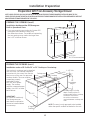 13
13
-
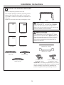 14
14
-
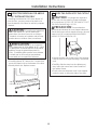 15
15
-
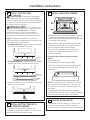 16
16
-
 17
17
-
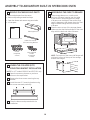 18
18
-
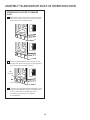 19
19
-
 20
20
-
 21
21
-
 22
22
-
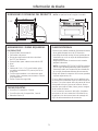 23
23
-
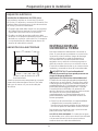 24
24
-
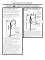 25
25
-
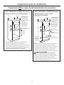 26
26
-
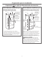 27
27
-
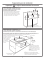 28
28
-
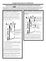 29
29
-
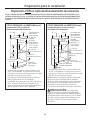 30
30
-
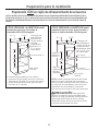 31
31
-
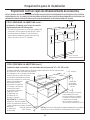 32
32
-
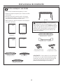 33
33
-
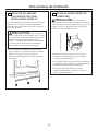 34
34
-
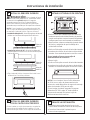 35
35
-
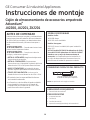 36
36
-
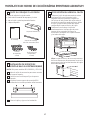 37
37
-
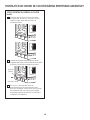 38
38
-
 39
39
-
 40
40


GE PSB9120SFSS Guía de instalación
- Categoría
- Cocinas
- Tipo
- Guía de instalación
- Este manual también es adecuado para
en otros idiomas
- English: GE PSB9120SFSS Installation guide


