GE Appliances PSB9240SFSS Guía de instalación
- Categoría
- Cocinas
- Tipo
- Guía de instalación
Este manual también es adecuado para

Installation
Instructions
Advantium
®
240V
Built-In SpeedCook
Ovens
PSB9240DF
PSB9240SF
ZSC2200
ZSC2201
ZSC2202
49-40690-1
MFL59060908
07-13 GE
Español
For a Spanish version of this manual, visit
our Website at GEAppliances.com.
Para consultar una version en español de
este manual de instrucciones, visite nuestro
sitio de internet GEAppliances.com.

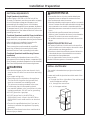
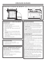
Safety Information
2
CONTENTS
Design Information
Models Available ......................................................................2
Product Dimensions and Clearances ............................4
Tools and Parts Required ....................................................4
Parts Supplied ...........................................................................4
Electrical Tools and Parts Required ................................4
Advance Planning ...................................................................4
Installation Preparation
Electrical Requirements .......................................................5
Install Junction Box ................................................................5
Preparing the Opening (Installation without
an accessory storage drawer) ................................. 6-7
Preparing the Opening (Installation with
an accessory storage drawer) ................................. 8-9
Installation Instructions
Step 1, Remove Packaging and Parts ........................10
Step 2, Route Conduit ........................................................11
Step 3, Install Bottom Trim ..............................................12
Step 4, Install Mounting Screws ....................................12
Step 5, Finalize Installation ..............................................12
BEFORE YOU BEGIN
Read these instructions completely and carefully.
IMPORTANT³ Save these instructions for
local inspector’s use.
IMPORTANT³ Observe all governing codes
and ordinances.
Note to Installer³ Be sure to leave these
instructions with the Consumer.
Note to Consumer³ Keep these instructions
with your Owner’s Manual for future reference.
Skill Level³ Installation of this appliance
requires basic mechanical and electrical skills.
Completion Time³ 1 Hour.
Proper installation is the responsibility of
the installer. Product failure due to improper
installation is not covered under the warranty. See
Owner’s Manual for warranty information.
IMPORTANT³ Use this oven only for
its intended purpose. Never use the oven for
warming or heating a room. Prolonged use of the
oven without proper ventilation can be hazardous.
CAUTION:
For personal safety, remove house fuse or oven
circuit breaker before beginning installation to
avoid severe or fatal shock injury.
CAUTION:
For personal safety, the mounting surface must
be capable of supporting the cabinet load, in
addition to the added weight of the 80-pound oven
and 30-pound drawer, plus additional oven loads
of up to 50 pounds or a total weight of up to 160
pounds.
CAUTION:
For personal safety, this product cannot be installed
in cabinet arrangements such as an
island, a peninsula or below a countertop.
MODELS AVAILABLE
Models:
PSB9240DFWW - White
PSB9240DFBB - Black
PSB9240SFSS - Stainless Steel
Monogram Models:
ZSC2200NWW–White
ZSC2200NBB–Black
ZSC2201NSS–Stainless Steel
Monogram Pro Range Models:
ZSC2202NSS–Stainless Steel
NOTE: This unit cannot be installed with an
accessory storage drawer.

Información de seguridad
ANTES DE COMENZAR
Lea estas instrucciones por completo y con
detenimiento.
IMPORTANTE³ Guarde estas instrucciones
para el uso de inspectores locales.
IMPORTANTE³ Cumpla con todos los
códigos y ordenanzas vigentes.
Nota al instalador³ Asegúrese de dejar estas
instrucciones con el Consumidor.
Nota al consumidor³ Mantenga estas
instrucciones con el Manual del Propietario para
referencia futura.
Nivel de capacidad³ La instalación de este
aparato requiere capacidades mecánicas y eléctricas
básicas.
Tiempo de finalización³ 1 hora.
El instalador tiene la responsabilidad de efectuar una
instalación adecuada. La Garantía no cubre las fallas
del producto debido a una instalación incorrecta. Ver
el Manual del Propietario para información sobre la
garantía.
IMPORTANTE³ Utilice este horno sólo con
el objetivo para el que fue creado. Nunca use el
horno para entibiar o calentar una habitación. El uso
prolongado del horno sin una ventilación adecuada
puede resultar peligroso.
PRECAUCIÓN:
Para seguridad personal, quite el fusible o el interruptor
de circuitos de la vivienda antes de comenzar la
instalación a fin de evitar una lesión grave o fatal.
PRECAUCIÓN:
Para seguridad personal, la superficie de montaje debe
poder soportar la carga del gabinete, además de las 80
libras del horno y las 30 libras del cajón, más las cargas
adicionales del horno de hasta 50 libras o un peso total
de hasta 160 libras.
PRECAUCIÓN:
Por razones de seguridad personal, este producto no se
puede instalar en arreglos de alacena tales como una
isla, una península o debajo de una mesada.
3

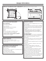
Design Information
4
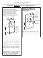
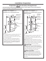
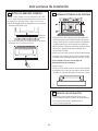
PRODUCT DIMENSIONS AND CLEARANCES NOTE: Appearance will vary by model.
TOOLS AND PARTS REQUIRED
(NOT SUPPLIED)
#2 Phillips screwdriver
Hand held drill
High speed drill bit, 3/32" diameter
3/8" slot head screwdriver
Level
Saw
2x4 or 2x2 lumber for installing runners
or 3/8" plywood for floor (if required)
Wood screws or other hardware for installing
runner or shelf to support oven (if required)
Safety glasses or goggles
PARTS SUPPLIED
6 brass screws (3 required, 3 extra)
5 color matched screws (4 required, 1 extra)
Bottom trim
ELECTRICAL TOOLS AND PARTS
REQUIRED (NOT SUPPLIED)
Junction box
Electrical cable (3-conductor or 4-conductor wire as
required by local codes)
UL-listed conduit connectors
Wire cutters and wire strippers
ADVANCE PLANNING
These ovens may be installed directly into a 30” wide
oven cabinet.
Cutout dimensions are NOT the same for installation
with or without an accessory storage drawer. Make
sure to use the correct cutout when preparing the
opening.
NOTE: Model ZSC2202 CANNOT be installed with
an accessory storage drawer. See Installation
Preparation Without an Accessory Storage Drawer
for this model.
IMPORTANT³ This oven is not approved for
use above another built-in Advantium Speedcook
oven, a side by side installation or below a
countertop.
For personal safety, this oven cannot be installed
in a cabinet arrangement such as an island or
peninsula.
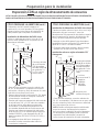
7KHRYHQPXVWEHLQVWDOOHGDWOHDVWµDERYH
the floor.
$OORZIRUFOHDUDQFHWRDGMDFHQWFRUQHUVZDOOV
drawers, etc.
&DELQHWVLQVWDOOHGDGMDFHQWWRZDOORYHQV
must have an adhesion spec of at least 194ºF
temperature rating.
The oven must be securely installed in a cabinet
that is firmly attached to the house structure.
Weight on the oven door could cause the oven
to tip and result in injury. Never allow anyone to
climb, sit, stand or hang on the oven door.
If installing the drawer accessory, the drawer must
be assembled to the oven prior to installation into
the cabinet. See the Accessory Storage Drawer
Assembly Instructions.
21-1/2”
1”
13”
19”
29-3/4”
1-1/10s
1-3/5s

Installation Preparation
5
ELECTRICAL REQUIREMENTS
Single Speedcook Installation
Product rating is 120/208 or 120/240 volt, 60 Hz,
30 amps. This product must be connected to a supply
circuit of the proper voltage and frequency and
protected by a time delay fuse or circuit breaker.
Power should be supplied from a separate, dedicated
30-ampere branch circuit. Wire size must conform to
the requirements of the National Electrical Code or the
prevailing local code.
Combined Speedcook and Wall Oven Installation
When installed in combination with a GE/Monogram
single wall oven, use separate electrical junction boxes.
Refer to single oven installation instructions for
electrical requirements of that product.
These connections must be made by a qualified
electrician. All electrical connections must meet
National Electrical Code or prevailing local codes.
Combined Speedcook and Warming Drawer
Installation
When installing the Speedcook oven over a GE or
Monogram electric warming drawer, a separate 120V,
60Hz, properly grounded receptacle must be installed.
See instructions packed with the warming drawer.
WARNING
The electrical power to the oven branch circuit
must be shut off while line connections are being
made.
Use copper wiring only.
Electrical ground is required on this appliance.
The free end of the green wire (ground wire)
must be connected to a suitable ground.
This wire must remain grounded to the oven.
If cold water pipe is interrupted by plastic,
non-metallic gaskets, union connections or other
insulating materials, DO NOT use for grounding.
DO NOT ground to a gas pipe.
DO NOT have a fuse in the NEUTRAL or
GROUNDING circuit. A fuse in the NEUTRAL or
GROUNDING circuit could result in an electrical
shock.
Check with a qualified electrician if you are in
doubt as to whether the appliance is properly
grounded.
Failure to follow these instructions could result in
serious injury or death.
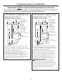
INSTALL JUNCTION BOX
The conduit is located at the top right on the back of
the oven.
Locate and install the junction box within reach of the
oven conduit.
Through the left or right sides of the cabinet wall
and into adjacent cabinet.
Or, through the cutout floor.
Or, in the upper cabinet.
ADVERTENCIA
El encendido eléctrico al circuito paralelo deberá estar
apagado mientras se realizan las conexiones de línea.
Use conductores de cobre únicamente.
Este electrodoméstico requiere que se realice una conexión
a tierra. El extremo libre del cable verde (cable a tierra) debe
estar conectado a una conexión a tierra adecuada. Este
cable debe permanecer conectado a la conexión a tierra del
horno.
Si la tubería de agua fría presenta interrupciones por
plásticos, juntas, conexiones de uniones u otros materiales
aislantes, NO use la misma como conexión a tierra.
NO se debe conectar a tierra en una tubería de suministro
de gas.
REQUISITOS ELÉCTRICOS (Cont)
NO posee un fusible en el circuito neutro o de conexión a
tierra. Un fusible en el circuito neutro o de conexión a tierra
podría ocasionar una descarga eléctrica.
Consulte a un electricista calificado o personal del servicio
si tiene dudas de que el electrodoméstico se encuentre
conectado a tierra apropiadamente.
Si no se siguen estas instrucciones, se podrán
producir lesiones graves o la muerte.
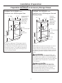
Cutout
Height

6
Installation Preparation
Preparation WITHOUT an Accessory Storage Drawer
PREPARE THE OPENING (CONT.)
Installation over a GE/Monogram
Warming Drawer:
NOTE: Additional clearances between the cutouts
may be required. Check to be sure the oven supports
above the Warming Drawer location do not obstruct
the required interior depth and height. See Warming
Drawer installation instructions for details.
30”
23-1/2”
25-1/4”
17-1/2”
36-3/4”
Min.
2” Min.
(3” recommended)
Per warming
drawer
requirement
Construct
Solid Bottom
Min. 3/8”
Plywood
Supported
by 2x4 or 2x2
Runners all
Four Sides
PREPARE THE OPENING
The Advantium 240V can be installed in
combination with other GE/Monogram appliances.
Always follow each product’s Installation
Instructions to complete the installation.
Single Advantium 240V Installation:
Order a 30” wide single oven cabinet or cut the
opening in a wall to the dimensions shown.
$OZD\VPDLQWDLQµPLQLPXPKHLJKWIURP
the floor to the cutout in any single or combined
installation.
$OORZµFDVHWULPRYHUODSRQWKHVLGHVDQG
7/8” overlap on the bottom of the opening for
all models. Allow 1-1/4” case trim overlap on the
top for models PSB9120 and 3/4” overlap on the
top for models ZSC2200, ZSC2200, ZSC2201 and
ZSC2202.
2YHQRYHUODSVZLOOFRQFHDOFXWHGJHVRQDOOVLGHV
of the opening.
When installed over a single oven or a warming
drawer, allow at least 2” between the two openings.
This separation will provide clearance for bottom
overlap of the Advantium 240V and the other
appliance overlaps.
Construct a solid oven floor of 3/8” min. thick plywood
supported by 2 x 4 or 2 x 2 runners on all sides.
7KHVXSSRUWPXVWEHOHYHODQGULJLGO\PRXQWHG
flush with the bottom edge of the cutout.
30”
23-1/2”
25-1/4”
17-1/2”
Construct
Base
Min. 3/8”
Plywood
Supported
by 2x4 or
2x2 Runners
all Four
Sides
36-3/4”
Min.

Installation Preparation
7
Preparation WITHOUT an Accessory Storage Drawer
PREPARE THE OPENING (CONT.)
Installation over a GE/Monogram Oven and
Warming Drawer:
NOTE: Additional clearances between the cutouts
may be required. Check to be sure the oven
supports above the Warming Drawer location do
not obstruct the required interior depth and height.
See Warming Drawer installation instructions for
details.
CAUTION: For personal safety, the
mounting surface must be capable of supporting
the cabinet load, in addition to the added weight
of this approximate 80-pound oven, plus additional
oven loads of up to 50 pounds or a total weight
of 130 pounds.
PRECAUCIÓN: Para seguridad
personal, la superficie de montaje debe poder
soportar la carga del gabinete, además del peso
aproximado de 80 libras del horno, más las
cargas adicionales del horno de hasta 50 libras
o un peso total de hasta 130 libras.
Construct
Solid Bottom
Min. 3/8”
Plywood
Supported by
2x4 or 2x2
Runners all
Four Sides
30”
23-1/2”
25-1/4”
17-1/2”
2” Min.
Per Oven
Requirement
45-1/4”
Min.
Per warming drawer requirement
2” Min.
(3” recommended)
PREPARE THE OPENING (CONT.)
Installation over a GE/Monogram Oven:
,I\RXDUHUHSODFLQJD*(0RQRJUDPHOHFWULF
double oven with the combined installation of
an Advantium 240V and a single oven, use the
dimensions shown. The middle rail separating
the two openings may need to be larger than
the 2” minimum shown.
30”
23-1/2”
25-1/4”
17-1/2”
2” Min.
(3” recommended)
45-1/4”
Min.
Construct Solid
Bottom Min.
3/8” Plywood
Supported by
2x4 or 2x2
Runners all
Four Sides
Per Oven
Requirement

8
Installation Preparation
Preparation WITH an Accessory Storage Drawer
NOTE: MODEL ZSC2202 CANNOT BE INSTALLED WITH AN ACCESSORY STORAGE DRAWER. SEE INSTALLATION PREPARATION
WITHOUT AN ACCESSORY STORAGE DRAWER FOR THIS MODEL.
Installation over a GE/Monogram
Warming Drawer:
*
For existing cutouts, a maximum width of 28-1/2”
is acceptable. If the opening is slightly wider,
secure a furring strip on each side of the cutout
for securing the oven.
NOTE: Additional clearances between the cutouts
may be required. Check to be sure the oven
supports above the Warming Drawer location do not
obstruct the required interior depth and height. See
Warming Drawer installation instructions for details.
30”
23-1/2”
25-1/4”
Min.*
21”
36-3/4”
Min.
2” Min.
(3” recommended)
Per warming
drawer
requirement
Construct
Solid Bottom
Min. 3/8”
Plywood
Supported
by 2x4 or 2x2
Runners all
Four Sides
PREPARE THE OPENING
The Advantium 240V can be installed in
combination with other GE/Monogram appliances.
Always follow each product’s Installation
Instructions to complete the installation.
Single Advantium 240V Installation:
Order a 30” wide single oven cabinet or cut the
opening in a wall to the dimensions shown.
* For existing cutouts, a maximum width of 28-1/2”
is acceptable. If the opening is slightly wider,
secure a furring strip on each side of the cutout
for securing the oven.
$OZD\VPDLQWDLQµPLQLPXPKHLJKWIURP
the floor to the cutout in any single or combined
installation.
Allow 3/4” to 2-1/8” case trim overlap on the sides
and 7/8” overlap on the bottom of the opening
for all models. The amount of overlap on the sides
depends on the actual cutout width. Allow 1-1/4”
case trim overlap on the top for model PSB9120
and 3/4” overlap on the top for models ZSC2200,
ZSC2200, ZSC2201 and ZSC2202.
2YHQRYHUODSVZLOOFRQFHDOFXWHGJHVRQDOOVLGHV
of the opening.
30”
23-1/2”
25-1/4”
Min.*
21”
Construct
Base
Min. 3/8”
Plywood
Supported
by 2x4 or
2x2 Runners
all Four
Sides
36-3/4”
Min.
PREPARE THE OPENING (CONT.)
Single Advantium 240V Installation (cont.)
When installed over a single oven or a warming
drawer, allow at least 2” between the two openings.
This separation will provide clearance for bottom
overlap of the Advantium 240V and the other
appliance overlaps.
Construct a solid oven floor of 3/8” min. thick plywood
supported by 2 x 4 or 2 x 2 runners on all sides.
7KHVXSSRUWPXVWEHOHYHODQGULJLGO\PRXQWHG
flush with the bottom edge of the cutout.

9
Installation Preparation
Preparation WITH an Accessory Storage Drawer
NOTE: MODEL ZSC2202 CANNOT BE INSTALLED WITH AN ACCESSORY STORAGE DRAWER. SEE INSTALLATION PREPARATION
WITHOUT AN ACCESSORY STORAGE DRAWER FOR THIS MODEL.
PREPARE THE OPENING (CONT.)
Installation over a GE/Monogram Oven and
Warming Drawer:
* For existing cutouts, a maximum width of 28-1/2”
is acceptable. If the opening is slightly wider,
secure a furring strip on each side of the cutout
for securing the oven.
NOTE: Additional clearances between the cutouts
may be required. Check to be sure the oven supports
above the Warming Drawer location do not obstruct
the required interior depth and height. See Warming
Drawer installation instructions for details.
CAUTION: For personal safety, the
mounting surface must be capable of supporting
the cabinet load, in addition to the added weight
of this approximate 80-pound oven and 30-pound
drawer, plus additional oven loads of up to 50
pounds or a total weight of 160 pounds.
PRECAUCIÓN: Para seguridad
personal, la superficie de montaje debe poder
soportar la carga del gabinete, además del peso
aproximado de 80 libras del horno y las 30 libras
del cajón, más las cargas adicionales del horno
de hasta 50 libras o un peso total de hasta
160 libras.
Construct
Solid Bottom
Min. 3/8”
Plywood
Supported by
2x4 or 2x2
Runners all
Four Sides
30”
23-1/2”
21”
2” Min.
Per Oven
Requirement
45-1/4”
Min.
Per warming drawer requirement
2” Min.
(3” recommended)
PREPARE THE OPENING (CONT.)
Installation over a GE/Monogram Oven:
* For existing cutouts, a maximum width of 28-1/2”
is acceptable. If the opening is slightly wider,
secure a furring strip on each side of the cutout
for securing the oven.
,I\RXDUHUHSODFLQJD*(0RQRJUDPHOHFWULF
double oven with the combined installation of
an Advantium 240V and a single oven, use the
dimensions shown. The middle rail separating
the two openings may need to be larger than
the 2” minimum shown.
30”
23-1/2”
25-1/4”
Min.*
21”
2” Min.
(3” recommended)
45-1/4”
Min.
Construct Solid
Bottom Min.
3/8” Plywood
Supported by
2x4 or 2x2
Runners all
Four Sides
Per Oven
Requirement
25-1/4”
Min.*

10
Installation Instructions
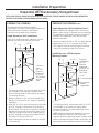
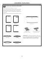
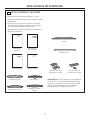
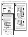
5HPRYHDOOSDFNLQJPDWHULDODQGWDSH
/RFDWHSDUWVSDFNDJHFRQWDLQLQJPRXQWLQJVFUHZV
5HPRYHWKHRYHQIURPWKHFDUWRQ'RQRWOLIWXQLW
by handle or conduit. Two people are required to lift
this oven.
2SHQWKHGRRUDQGUHPRYHDQ\SDFNDJLQJLQRYHQ
1
REMOVE THE PACKAGING AND PARTS
Owner’s
Manual
Owner’s Manual
Installation
Instructions
Glass Tray
Metal Grill Tray
Metal Trays (2)
Turntable Ring
Bottom Trim
Rack
6 Brass Screws
(3 required, 3 extra)
IMPORTANT: If installing the Advantium 240V Oven
with an accessory storage drawer, read the storage
drawer assembly instructions to assemble the
products together before proceeding to Step 2.
Cook Book
5 Color Matched Screws
(4 required, 1 extra)
Cooking Guide
Cooking
Guide

Installation Instructions
11
2
ROUTE CONDUIT THROUGH
CUTOUT (CONT.)
When connecting to a 3-conductor branch circuit:
Connect oven red lead to branch circuit red lead.
Connect oven black lead to branch circuit black
lead.
Connect oven green ground lead and white lead
to branch circuit neutral (white or gray).
When connecting to a 4-conductor branch
circuit:
Connect oven red lead to branch circuit red lead.
Connect oven black lead to branch circuit black
lead.
Break connection between oven white lead and
oven green ground lead.
Connect oven white lead to branch circuit neutral
lead (white or gray).
Connect oven green ground lead to branch circuit
ground lead (green or bare copper).
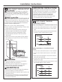
2
ROUTE CONDUIT THROUGH CUTOUT
CAUTION: Two people are required to
lift the oven into the opening. Grasp the bottom
at front and rear. Discard foam base. DO NOT USE
HANDLE OR CONDUIT TO LIFT THE OVEN. DAMAGE
WILL OCCUR.
PRECAUCIÓN:
Se requiere contar con
dos personas para colocar el horno en la abertura. Se
deberá tomar la parte inferior sobre la parte frontal
y trasera. Descarte la base de gomaespuma. NO USE
LA MANIJA NI LOS CONDUCTOS PARA LEVANTAR EL
HORNO. SE PRODUCIRÁN DAÑOS.
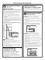
With oven in front of the cabinet opening:
Insert conduit into cabinet opening. Connect oven
wiring and branch circuit.
Lift the oven into the opening while continuing to
feed the conduit in the direction of the installed
junction box. Be sure the conduit does not get
pinched between the back of the oven and the
cabinet wall.
Leave oven a few inches forward of the cabinet
front frame. Do not push the unit all of the way
into the cutout.
WARNING
Disconnect power to the junction box before
making the electrical connection.
Electrical ground is required on this appliance.
Do not connect the electrical supply until
appliance is permanently grounded.
ADVERTENCIA
Desconecte la corriente de la caja de empalmes
antes de realizar la conexión eléctrica.
Este electrodoméstico requiere que se realice una
conexión a tierra.
No conecte al suministro de corriente hasta que
el electrodoméstico se haya conectado a tierra
de forma permanente.
(Oven shown without
accessory storage drawer.)
GROUNDING INSTRUCTIONS
This appliance must be connected to a grounded,
metallic, permanent wiring system, or an equipment
grounding connector should be run with the circuit
conductors and connected to the equipment
grounding terminal or lead on the appliance.
Failure to follow these instructions could result
in fire, personal injury or electrical shock.

12
Installation Instructions
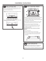
3
INSTALL BOTTOM TRIM
NOTE: If installing the Advantium 240 Oven with an
accessory storage drawer, the bottom trim is not
required. Proceed to Step 4.
Align bottom trim tabs to slots in the bottom of the
oven.
Secure the bottom trim to the bottom of the oven
using 3 brass screws provided.
4
INSTALL MOUNTING SCREWS
Slide the oven the remaining way into the opening
so that the side flanges and control panel are
against the cabinet frame. Make sure that the oven
is centered in the opening.
Open the door, place a turntable tray in the oven
and make sure that the tray in the unit is level.
Drill pilot holes through the side flanges.
Drive the color matched screws into the side
flanges. It is recommended that the screws
be hand tightened.
If installing oven with an accessory storage
drawer:
Open the drawer.
Drill pilot holes through the side flanges.
Drive color match screws into the side flanges.
It is recommended that the screws be hand
tightened.
5 FINALIZE INSTALLATION
Turn power on at the source. The interior light
should come on when the door is opened.
Refer to Owner’s Manual for operating instructions.

NOTE: Appearance will vary by model.
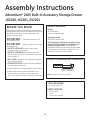
Assembly Instructions
Advantium
®
240V Built-In Accessory Storage Drawer
JX2200, JX2201, ZX2201
BEFORE YOU BEGIN
Read these instructions completely and carefully. Read
the Installation Instructions for the Advantium 240V oven
completely and carefully for cutout dimensions and
step-by-step instructions.
IMPORTANT³ Save these instructions for
local inspector’s use.
IMPORTANT³ Observe all governing codes
and ordinances.
NOTE TO INSTALLER: Be sure to leave these
instructions with the Consumer.
NOTE TO CONSUMER: Keep these instructions
with your Advantium 240V Oven Owner’s Manual for
future reference.
SKILL LEVEL: Installation of this appliance requires
basic mechanical skills.
COMPLETION TIME: One hour with the installation
of an Advantium 240V oven.
Proper installation is the responsibility of the installer.
Product failure due to improper installation is not
covered under the Warranty. See the Advantium
240V Oven Owner’s Manual for warranty information.
TOOLS REQUIRED
3KLOOLSVVFUHZGULYHU
PARTS SUPPLIED
6LGH6XSSRUWV
6FUHZV
6FUHZVFRORUPDWFKHG
MODELS AVAILABLE
Models:
JX2200BB–Black
JX2201SS–Stainless Steel
Monogram Models:
ZX2201SS–Stainless Steel
NOTE: Advantium 240V Built-In SpeedCook Oven
model ZSC2202SS CANNOT be installed with an
accessory storage drawer. See Installation
Preparation Without an Accessory Storage Drawer
in the Advantium 240V Built-In SpeedCook Oven
Installation Instructions for this model.
PRODUCT DIMENSIONS AND CLEARANCES
Allow 15” clearance
when fully open
5”
13

1
REMOVE PACKAGING AND PARTS
5HPRYHWKHGUDZHUIURPWKHFDUWRQ
5HPRYHDOOSDFNLQJPDWHULDODQGWDSH
2SHQWKHGUDZHUDQGUHPRYHDQ\SDUWVLQVLGH
/RFDWHSDUWV
ASSEMBLY TO ADVANTIUM 240V BUILT-IN SPEEDCOOK OVEN
Assembly
Instructions
Side Supports (2)
Screws (2 Sets)
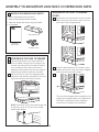
ASSEMBLING THE OVEN TO DRAWER
(CONT.)
C
Remove the front two bottom screws on each
side of the oven and the top center screw on
each side of the storage drawer.
D
Place the side supports into the tabs on the
drawer and secure using the screws supplied
and the screws removed in Step C.
E
The oven and storage drawer assembly is now
ready to be installed. Return to the Advantium
240V Built-In SpeedCook Oven Installation
Instructions to complete the installation.
2
ASSEMBLING THE OVEN TO DRAWER
A
Place storage drawer on a surface with the
front of drawer hanging over the edge of the
surface. Not placing the front edge of drawer
over the edge of the surface may result in
damage to the drawer since the front edge of
drawer hangs below the bottom of drawer.
B
Place the oven on top of the storage drawer.
Make sure that the back and sides of the oven
align with the back and sides of drawer.
NOTE: The bottom of the oven side flanges will
sit directly in front of the top of the storage
drawer side flanges.
14

15
Notes

Printed in Korea
NOTE: While performing installations described in this book,
safety glasses or goggles should be worn.
NOTE: Product improvement is a continuing endeavor at
General Electric. Therefore, materials, appearance and
specifications are subject to change without notice.
GE Appliances & Lighting
Appliances
General Electric Company
Louisville, KY 40225
GEAppliances.com

Instrucciones
de instalación
Hornos de cocción
rápida empotrados
de 240V Advantium
®
PSB9240DF
PSB9240SF
ZSC2200
ZSC2201
ZSC2202
49-40690-1
MFL59060908
06-13 GE

Información de seguridad
2
CONTENIDOS
Información de diseño
Modelos disponibles ..............................................................2
Dimensiones y distancias del producto .......................3
Herramientas y piezas requeridas ..................................3
Piezas provistas .......................................................................3
Herramientas eléctricas y piezas requeridas ............3
Planificación previa ................................................................3
Preparación para la instalación
Requisitos eléctricos ..............................................................4
Instale la caja de conexiones ............................................4
Preparación de la abertura (instalación sin un
cajón de almacenamiento de accesorios) .........5-6
Preparación de la abertura (instalación con un
cajón de almacenamiento de accesorios) .........7-8
Instrucciones de instalación
Paso 1, Quite el empaque y las piezas .........................9
Paso 2, Instale los conductos .........................................10
Paso 3, Instale el reborde inferior ................................11
Paso 4, Instale los tornillos de montaje .....................11
Paso 5, Finalice la instalación ........................................11
ANTES DE COMENZAR
Lea estas instrucciones por completo y con
detenimiento.
IMPORTANTE³ Guarde estas instrucciones
para el uso de inspectores locales.
IMPORTANTE³ Cumpla con todos los
códigos y ordenanzas vigentes.
Nota al instalador³ Asegúrese de dejar estas
instrucciones con el Consumidor.
Nota al consumidor³ Mantenga estas
instrucciones con el Manual del Propietario para
referencia futura.
Nivel de capacidad³ La instalación de este
aparato requiere capacidades mecánicas y eléctricas
básicas.
Tiempo de finalización³ 1 hora.
El instalador tiene la responsabilidad de efectuar una
instalación adecuada. La Garantía no cubre las fallas
del producto debido a una instalación incorrecta. Ver
el Manual del Propietario para información sobre la
garantía.
IMPORTANTE³ Utilice este horno sólo con
el objetivo para el que fue creado. Nunca use el
horno para entibiar o calentar una habitación. El uso
prolongado del horno sin una ventilación adecuada
puede resultar peligroso.
PRECAUCIÓN:
Para seguridad personal, quite el fusible o el interruptor
de circuitos de la vivienda antes de comenzar la
instalación a fin de evitar una lesión grave o fatal.
PRECAUCIÓN:
Para seguridad personal, la superficie de montaje debe
poder soportar la carga del gabinete, además de las 80
libras del horno y las 30 libras del cajón, más las cargas
adicionales del horno de hasta 50 libras o un peso total
de hasta 160 libras.
PRECAUCIÓN:
Por razones de seguridad personal, este producto no se
puede instalar en arreglos de alacena tales como una
isla, una península o debajo de una mesada.
MODELOS DISPONIBLES
Modelos Profile:
PSB9240DFWW–Blanco*
PSB9240DFBB–Negro
PSB9240SFSS–Acero inoxidable
Modelos Monogram:
ZSC2200NWW-Blanco
ZSC2200NBB-Negro
ZSC2201SS–Acero inoxidable
Modelos Monogram Pro Range:
ZSC2202NSS–Acero inoxidable
NOTE: Esta unidad no puede instalarse con un cajón
de almacenamiento de accesorios.

Información de diseño
3
DIMENSIONES Y DISTANCIAS DEL PRODUCTO NOTA: La apariencia varía según el modelo.
HERRAMIENTAS Y PIEZAS REQUERIDAS
(NO PROVISTAS)
Destornillador de estrella #2
Perforadora de mano
Broca para perforadora de alta velocidad
de 3/32” de diámetro
Destornillador para cabeza ranurada de 3/8”
Nivel
Sierra
Madera de 2 x 4 o 2 x 2 para instalar guías
o madera terciada de 3/8” para el piso (si se
requiriera)
Tornillos para madera u otro elemento para
instalar guías o estante para sostener el horno
(si se requiriera)
Gafas o lentes de seguridad
PIEZAS PROVISTAS
6 tornillos (3 necesarios, 3 extra)
5 tornillos de color (4 requeridos, 1 extra)
Reborde inferior (2)
PLANIFICACIÓN PREVIA
Estos hornos pueden instalarse directamente dentro
de un gabinete para horno de 30” de ancho.
Las dimensiones del recorte NO son iguales para la
instalación con o sin un cajón de almacenamiento
para accesorios.
Asegúrese de utilizar el recorte correcto cuando
prepare la abertura
NOTA: Los modelos ZSC1202 NO PUEDEN instalarse
con un cajón de almacenamiento para accesorios.
Para este modelo, ver Preparación para instalación
sin un cajón de almacenamiento para accesorios.
IMPORTANTE ³ No se aprueba el uso de
este horno sobre otro horno Advantium Speedcook
incorporado, la instalación de uno al lado del otro o
debajo de la mesada.
Por razones de seguridad personal, este producto
no se puede instalar en arreglos de alacena tales
como una isla o península.
(OKRUQRGHEHVHULQVWDODGRDSRUORPHQRVµ
sobre el piso.
'HMHXQDGLVWDQFLDUHVSHFWRGHULQFRQHVSDUHGHV
cajones adyacentes, etc.
/RVJDELQHWHVLQVWDODGRVHQIRUPDDG\DFHQWH
a los hornos de pared deberán contar con una
adhesión específica de un índice de temperatura
de por lo menos 194º F.
El horno debe instalarse bien en un gabinete que
se encuentre firmemente sujeto a la estructura de
la casa. Si se coloca peso sobre la puerta del horno,
éste puede volcarse y provocar lesiones. Nunca
permita que nadie se suba, siente, pare o cuelgue
de la puerta del horno.
Si va a instalar el accesorio del cajón, éste debe
montarse en el horno antes de la instalación en
el gabinete. Ver las Instrucciones de montaje del
cajón de almacenamiento de accesorios.
21-1/2”
1”
13”
19”
29-3/4”
PIEZAS Y HERRAMIENTAS ELÉCTRICAS
REQUERIDAS (NO SUMINISTRADAS)
Caja de Empalmes
Cable eléctrico (cable con 3 conductores o 4
conductores, de acuerdo con lo requerido por los
códigos locales)
Cables conectores de la lista de UL
Cortacables y pelacables
1-1/10s
1-3/5s

Preparación para la instalación
4
REQUISITOS ELÉCTRICOS
INSTALACIÓN DE UN SPEEDCOOK INDIVIDUAL
La potencia del producto es de 120/208 o 120/240
volt, 60 Hz, 30 amperes. Este producto debe ser
conectado a un circuito con el suministro correcto
de voltaje y frecuencia y debe estar protegido por
un fusible de retraso de tiempo o por un disyuntor.
La potencia deberá ser suministrada a través de un
circuito paralelo aparte de 30 amperes. El tamaño del
cable deberá ser conforme a los requisitos del Código
Nacional de Electricidad (National Electrical Code) o del
código local obligatorio.
INSTALACIÓN DE SPEEDCOOK COMBINADO Y
HORNO DE PARED
Al realizar la instalación en combinación con un horno
de pared individual de GE/ Monogram, use cajas de
cableados eléctricos aparte.
Para conocer los requisitos eléctricos de ese producto,
consulte las instrucciones de instalación para un horno
individual.
Estas conexiones deben ser realizadas por un
electricista calificado. Todas las conexiones eléctricas
deben cumplir con el Código Nacional de Electricidad
(National Electrical Code) o con los códigos locales
obligatorios.
INSTALACIÓN DE SPEEDCOOK COMBINADO Y
DEL CAJÓN DE CALENTAMIENTO
Al instalar el horno Speedcook sobre un cajón de
calentamiento eléctrico de GE o Monogram, se deberá
instalar un receptáculo correctamente conectado
a tierra de 120V, 60Hz. Consulte las instrucciones
embaladas con el cajón calentador.
ADVERTENCIA
El encendido eléctrico al circuito paralelo deberá estar
apagado mientras se realizan las conexiones de línea.
Use conductores de cobre únicamente.
Este electrodoméstico requiere que se realice una conexión
a tierra. El extremo libre del cable verde (cable a tierra) debe
estar conectado a una conexión a tierra adecuada. Este
cable debe permanecer conectado a la conexión a tierra del
horno.
Si la tubería de agua fría presenta interrupciones por
plásticos, juntas, conexiones de uniones u otros materiales
aislantes, NO use la misma como conexión a tierra.
NO se debe conectar a tierra en una tubería de suministro
de gas.
INSTALACIÓN DE LA CAJA DE EMPALMES
El conducto está ubicado del lado superior derecho de
la parte trasera del horno.
Ubique e instale la caja de empalmes dentro del
alcance del conducto del horno.
A través de los lados izquierdo y derecho de la
pared del gabinete y en un gabinete adyacente.
O a través del piso de recorte.
O en el gabinete superior.
Altura del
Recorte
REQUISITOS ELÉCTRICOS (Cont)
NO posee un fusible en el circuito neutro o de conexión
a tierra. Un fusible en el circuito neutro o de conexión a
tierra podría ocasionar una descarga eléctrica.
Consulte a un electricista calificado o personal del servicio
si tiene dudas de que el electrodoméstico se encuentre
conectado a tierra apropiadamente.
Si no se siguen estas instrucciones, se podrán
producir lesiones graves o la muerte.

5
Preparación para la instalación
Preparación SIN un cajón de almacenamiento de accesorios
CÓMO PREPARAR LA ABERTURA (cont.)
Instalación sobre un cajón calentador GE/
Monogram:
NOTA: Pueden necesitarse espacios adicionales entre
los recortes. Verifique que los soportes del horno
sobre la ubicación de cajón calentador no obstruyan
la profundidad y altura interiores requeridas. Para
más detalles, consulte las instrucciones de instalación
del cajón calentador.
30”
23-1/2”
25-1/4”
17-1/2”
2” mínimo
(se recomienda 3”)
Según los
requisitos
del cajón
calentador
Construya una
base sólida de
un mínimo de
3/8” de madera
terciada
sostenida por
guías de 2 x 4
o 2 x 2 en los
cuatro lados
CÓMO PREPARAR LA ABERTURA
El Advantium de 240V puede instalarse en
combinación con otros aparatos GE/Monogram.
Siempre siga las Instrucciones de instalación de
cada producto para completar la instalación.
Instalación de Advantium de 240V único:
Solicite un gabinete para horno único de 30” de
ancho o corte la abertura en una pared con las
dimensiones indicadas.
6LHPSUHGHMHXQDDOWXUDPtQLPDGHµGHVGH
el piso hasta el recorte en cualquier instalación,
ya sea simple o combinada.
3HUPLWDTXHKD\DXQDVXSHUSRVLFLyQGHOERUGH
de la caja de 2-1/8” sobre los costados y una
superposición de 7/8” en la parte inferior de la
abertura para todos los modelos. Permita que
haya una superposición del borde de la caja
de 1-1/4” en la parte superior para los modelos
PSB9120 y una superposición de 3/4” para los
modelos ZSC2200, ZSC2200, ZSC2201 y ZSC2202.
/DVVXSHUSRVLFLRQHVGHOKRUQRVLUYHQSDUD
esconder los lados cortados sobre todos los
costados de la abertura.
Cuando se instalan sobre un horno único o un
cajón calentador, deje por lo menos 2” entre las
dos aberturas. Esta separación brindará un espacio
para la superposición superior del Advantium de
240V y las otras superposiciones del aparato.
Construya un piso sólido para el horno de madera
terciada de un grosor mínimo de 3/8” sostenido por
guías de 2 x 4 o 2 x 2 en todos los lados.
(OVRSRUWHGHEHHVWDUQLYHODGR\ELHQPRQWDGR
alineado con el lado inferior del recorte.
30”
23-1/2”
25-1/4”
17-1/2”
Construya
la base de
un mínimo
de 3/8”
de madera
terciada
sostenido
por guías de
2 x 4 o 2 x 2
en los cuatro
lados
36-3/4”
Min.
36-3/4”
Min.

Preparación para la instalación
6
Preparación SIN un cajón de almacenamiento de accesorios
CÓMO PREPARAR LA ABERTURA (cont.)
Instalación sobre un horno y cajón
calentador GE/Monogram:
NOTA: Pueden necesitarse espacios adicionales
entre los recortes. Verifique que los soportes
del horno sobre la ubicación de cajón calentador
no obstruyan la profundidad y altura interiores
requeridas. Para más detalles, consulte las
instrucciones de instalación del cajón calentador.
PRECAUCIÓN: Para seguridad
personal, la superficie de montaje debe poder
soportar la carga del gabinete, además del peso
aproximado de 80 libras del horno, más las
cargas adicionales del horno de hasta 50 libras
o un peso total de hasta 130 libras.
Construya una
base sólida de
un mínimo de
3/8” de madera
terciada
sostenida por
guías de 2 x 4
o 2 x 2 en los
cuatro lados
30”
23-1/2”
25-1/4”
17-1/2”
2” mínimo
(se recomienda 3”)
Según los
requisitos del horno
2” mínimo
(se recomienda 3”)
CÓMO PREPARAR LA ABERTURA (cont.)
Instalación sobre un horno GE/Monogram:
6LXVWHGHVWiUHHPSOD]DQGRXQKRUQRHOpFWULFR
doble GE/Monogram con la instalación
combinada de un Advantium de 120V y un horno
único, utilice las dimensiones indicadas. El riel
medio que separa las dos aberturas puede tener
que ser mayor al mínimo de 2” indicado.
30”
23-1/2”
25-1/4”
17-1/2”
2” mínimo
(se recomienda 3”)
Construya una
base sólida de
un mínimo de
3/8” de madera
terciada
sostenida por
guías de 2 x 4
o 2 x 2 en los
cuatro lados
Según los
requisitos
del horno
Según los requisitos del cajón calentador
45-1/4”
mínimo
45-1/4”
mínimo

7
Preparación para la instalación
Preparación CON un cajón de almacenamiento de accesorios
NOTA: EL MODELO ZSC2202 NO PUEDEN INSTALARSE CON UN CAJÓN DE ALMACENAMIENTO DE ACCESORIOS. VER PREPARACIÓN
PARA LA INSTALACIÓN SIN UN CAJÓN DE ALMACENAMIENTO DE ACCESORIOS PARA ESTE MODELO.
Instalación de Advantium de 240V único (cont.)
Cuando se instalan sobre un horno único o un cajón
calentador, deje por lo menos 2” entre las
dos aberturas. Esta separación brindará un espacio
para la superposición superior del Advantium de
120V y las otras superposiciones del aparato.
Construya un piso sólido para el horno de madera
terciada de un grosor mínimo de 3/8” sostenido por
guías de 2 x 4 o 2 x 2 en todos los lados.
(OVRSRUWHGHEHHVWDUQLYHODGR\ELHQPRQWDGR
alineado con el lado inferior del recorte.
Instalación sobre un cajón calentador GE/
Monogram:
* Para recortes existentes, un ancho máximo de
28-1/2” es aceptable. Si la abertura es un poco más
ancha, coloque un listón de enrasar en cada lado
del recorte para fijar el horno.
NOTA: Pueden necesitarse espacios adicionales
entre los recortes. Verifique que los soportes
del horno sobre la ubicación de cajón calentador
no obstruyan la profundidad y altura interiores
requeridas. Para más detalles, consulte las
instrucciones de instalación del cajón calentador.
CÓMO PREPARAR LA ABERTURA (cont.)
El Advantium de 240V puede instalarse en
combinación con otros aparatos GE/Monogram.
Siempre siga las Instrucciones de instalación de
cada producto para completar la instalación.
Instalación de Advantium de 240V único:
Solicite un gabinete para horno único de 30” de
ancho o corte la abertura en una pared con las
dimensiones indicadas.
30”
23-1/2”
25-1/4”
mínimo
21”
Construya la base
de un mínimo de
3/8” de madera
terciada sostenida
por guías de 2 x
4 o 2 x 2 en los
cuatro lados
CÓMO PREPARAR LA ABERTURA (cont.)
36-3/4s
mínimo*
* Para recortes existentes, un ancho máximo de
28-1/2” es aceptable. Si la abertura es un poco
más ancha, coloque un listón de enrasar en cada
lado del recorte para fijar el horno.
6LHPSUHGHMHXQDDOWXUDPtQLPDGHµGHVGH
el piso hasta el recorte en cualquier instalación,
ya sea simple o combinada.
Permita que haya una superposición del borde de
la caja de entre 3/4” y 2-1/8” sobre los costados
en la parte inferior de la abertura para todos
los modelos. La cantidad de superposición en
los costados depende del ancho de recorte real.
Permita que haya una superposición del borde
de la caja de 1-1/4” en la parte superior para los
modelos PSB9120 y una superposición de 3/4”
para los modelos ZSC2200, ZSC2200, ZSC2201 y
ZSC2202.
/DVVXSHUSRVLFLRQHVGHOKRUQRVLUYHQSDUD
esconder los lados cortados sobre todos los
costados de la abertura.
30”
23-1/2”
25-1/4”
mínimo
21”
2” mínimo
(se recomienda 3”)
Según los
requisitos
del cajón
calentador
Construya una base
sólida de un mínimo
de 3/8” de madera
terciada sostenida
por guías de 2 x 4 o
2 x 2 en los cuatro
lados
* Requerido para
modelos Monogram
36-3/4s
mínimo*

8
Preparación para la instalación
Preparación CON un cajón de almacenamiento de accesorios
NOTA: EL MODELO ZSC2202 NO PUEDEN INSTALARSE CON UN CAJÓN DE ALMACENAMIENTO DE ACCESORIOS. VER PREPARACIÓN
PARA LA INSTALACIÓN SIN UN CAJÓN DE ALMACENAMIENTO DE ACCESORIOS PARA ESTE MODELO.
CÓMO PREPARAR LA ABERTURA (cont.)
Instalación sobre un horno y cajón
calentador GE/Monogram:
* Para recortes existentes, un ancho máximo de
28-1/2” es aceptable. Si la abertura es un poco
más ancha, coloque un listón de enrasar en cada
lado del recorte para fijar el horno.
NOTA: Pueden necesitarse espacios adicionales
entre los recortes. Verifique que los soportes
del horno sobre la ubicación de cajón calentador
no obstruyan la profundidad y altura interiores
requeridas. Para más detalles, consulte las
instrucciones de instalación del cajón calentador.
PRECAUCIÓN: Para seguridad
personal, la superficie de montaje debe poder
soportar la carga del gabinete, además del peso
aproximado de 80 libras del horno y las 30 libras
del cajón, más las cargas adicionales del horno
de hasta 50 libras o un peso total de hasta
160 libras.
Construya una
base sólida de
un mínimo de
3/8” de madera
terciada
sostenida por
guías de 2 x 4
o 2 x 2 en los
cuatro lados
30”
23-1/2”
21”
2” mínimo
(se recomienda 3”)
Según los requisitos
del horno
2” mínimo
(se recomienda 3”)
CÓMO PREPARAR LA ABERTURA (cont.)
Preparación CON un cajón de
almacenamiento de accesorios:
* Para recortes existentes, un ancho máximo de
28-1/2” es aceptable. Si la abertura es un poco
más ancha, coloque un listón de enrasar en cada
lado del recorte para fijar el horno.
6LXVWHGHVWiUHHPSOD]DQGRXQKRUQRHOpFWULFR
doble GE/Monogram con la instalación
combinada de un Advantium de 240V y un horno
único, utilice las dimensiones indicadas. El riel
medio que separa las dos aberturas puede tener
que ser mayor al mínimo de 2” indicado.
30”
23-1/2”
25-1/4”
mínimo*
21”
2” mínimo
(se recomienda 3”)
Construya una
base sólida
de un mínimo
de 3/8” de
madera
terciada
sostenida por
guías de 2 x 4
o 2 x 2 en los
cuatro lados
Según los
requisitos del horno
25-1/4”
mínimo*
Según los requisitos
del cajón calentador
45-1/4s
mínimo
45-1/4s
mínimo

1
QUITE EL EMPAQUE Y LAS PIEZAS
9
Instrucciones de instalación
4XLWHWRGRHOPDWHULDOGHHPSDTXH\ODFLQWD
8ELTXHHOSDTXHWHGHSLH]DVTXHFRQWLHQHWRUQLOORV
de montaje.
4XLWHHOKRUQRGHODFDMDGHFDUWyQ1ROHYDQWH
la unidad de la manija o conducto. Se necesitan
dos personas para levantar este horno.
$EUDODSXHUWD\TXLWHORVHOHPHQWRVGHHPSDTXH
del interior del horno.
Owner’s
Manual
Manual del
Propietario
Instrucciones
de instalación
Bandeja de vidrio
Bandejas de metal (2)
Anillo giratorio
6 tornillos de bronce
(3 requeridos, 3 extra)
IMPORTANTE: Si va a instalar el horno Advantium
de 120V con un cajón de almacenamiento para
accesorios, lea las instrucciones de montaje del
cajón de almacenamiento para instalar los
productos antes de seguir con el Paso 2.
Libro de cocina
5 tornillos de color
(4 requeridos, 1 extra)
Guía de cocción
Cooking
Guide
Bandeja con Rejilla
Metálica
Reborde inferior
Estante

Instrucciones de instalación
10
2
ENRUTE EL CONDUCTO A TRAVÉS
DEL RECORTE (CONT.)
Al conectar a un circuito de empalmes de 3
conductores:
Conecte el conductor de suministro rojo del
horno al conductor de suministro rojo del circuito
de empalmes.
Conecte el conductor de suministro negro del
horno al conductor de suministro negro del circuito
de empalmes.
Conecte el conductor de suministro verde del
horno y el conductor de suministro blanco al
neutro del circuito de empalmes (blanco o gris).
Al conectar a un circuito de empalmes de 4
conductores:
Conecte el conductor de suministro rojo del
horno al conductor de suministro rojo del circuito
de empalmes.
Conecte el conductor de suministro negro del
horno al conductor de suministro negro del circuito
de empalmes.
Divida la conexión entre el conductor de suministro
blanco del horno y el conductor de suministro
verde del horno.
Conecte el conductor de suministro blanco del
horno al conductor de suministro neutro del
circuito de empalmes (blanco o gris).
Conecte el conductor de suministro verde de tierra
del horno al conductor de suministro de tierra
del circuito de empalmes (verde o de cobre sin
revestimiento).
2
ENRUTE EL CONDUCTO A TRAVÉS
DEL RECORTE
PRECAUCIÓN:
Se requiere contar con
dos personas para colocar el horno en la abertura. Se
deberá tomar la parte inferior sobre la parte frontal
y trasera. Descarte la base de gomaespuma. NO USE
LA MANIJA NI LOS CONDUCTOS PARA LEVANTAR EL
HORNO. SE PRODUCIRÁN DAÑOS.
Con el horno frente a la abertura del gabinete:
Inserte el conducto en la abertura del gabinete.
Conecte el cableado del horno y el circuito de
empalmes.
Coloque el horno en la abertura mientras continúa
alimentando el conducto en la dirección de la caja de
empalmes instalada. Asegúrese de que el conducto
no sea pellizcado entre la parte trasera del horno y la
pared del gabinete.
Deje el horno unas pocas pulgadas por delante
de la estructura frontal del gabinete. No empuje
la unidad hasta el recorte.
ADVERTENCIA
Desconecte la corriente de la caja de empalmes
antes de realizar la conexión eléctrica.
Este electrodoméstico requiere que se realice una
conexión a tierra.
No conecte al suministro de corriente hasta que
el electrodoméstico se haya conectado a tierra
de forma permanente.
(Oven shown without
accessory storage drawer.)
INSTRUCCIONES DE
CONEXIÓN A TIERRA
Este electrodoméstico debe estar conectado a un
sistema de cableado de metal permanente con
conexión a tierra o se debe tender un conducto
para la conexión a tierra del equipo con los
conductores del circuito y conectado al terminal de
tierra del equipo o al conductor de suministro del
electrodoméstico.
INSTRUCCIONES DE
CONEXIÓN A TIERRA (CONT.)
Si no se siguen estas instrucciones, se podrán
producir incendios, lesiones personales o descargas
eléctricas.

11
Instrucciones de instalación
4
INSTALE LOS TORNILLOS DE MONTAJE
Deslice el horno por la distancia que falta dentro de
la abertura para que las bridas laterales y el panel de
control se encuentren contra el armazón del gabinete.
Verifique que el horno esté centrado en la abertura.
Abra la puerta, coloque una bandeja giratoria dentro
del horno y asegúrese de que la bandeja de la
unidad esté nivelada.
Perfore orificios piloto a través de las bridas laterales.
Introduzca los tornillos de color dentro de las bridas
laterales. Se recomienda ajustar los tornillos a mano.
Si va a instalar el horno con un cajón de
almacenamiento de accesorios:
Abra el cajón.
Perfore orificios piloto a través de las bridas laterales.
Introduzca los tornillos de color dentro de las bridas
laterales. Se recomienda ajustar los tornillos a mano.
5 FINALICE LA INSTALACIÓN
Encienda la electricidad desde la fuente. La luz
interior debe encenderse cuando se abre la puerta.
Consulte el Manual del Propietario para
instrucciones operativas.
3
INSTALE EL REBORDE INFERIOR
NOTA: Si va a instalar el horno Advantium de 240V
con un cajón de almacenamiento de accesorios, no
se requiere el reborde inferior. Siga con el Paso 4.
Alinee las lengüetas del reborde plástico con las ranuras
de la parte inferior del horno.
Fije el reborde inferior a la parte inferior del horno
utilizando los 3 tornillos provistos.
Reborde
plástico

12
Instrucciones de montaje
Cajón de almacenamiento de accesorios empotrado
Advantium
®
JX2200, JX2201, ZX2201
ANTES DE COMENZAR
Lea estas instrucciones por completo y con detenimiento.
Lea las Instrucciones de instalación del horno Advantium
de 240V por completo y con detenimiento sobre las
dimensiones del recorte y las instrucciones paso a paso.
IMPORTANTE³ Guarde estas instrucciones
para el uso de inspectores locales.
IMPORTANTE³ Cumpla con todos los
códigos y ordenanzas vigentes.
NOTA AL INSTALADOR: Asegúrese de dejar estas
instrucciones al consumidor.
NOTA AL CONSUMIDOR: Conserve estas
instrucciones con el Manual del Propietario del horno
Advantium de 240V para referencia futura.
NIVEL DE CAPACIDAD: La instalación de este
aparato requiere capacidades mecánicas básicas.
TIEMPO DE FINALIZACIÓN: Una hora con la
instalación de un horno Advantium de 240V.
El instalador tiene la responsabilidad de efectuar
una instalación adecuada.
La Garantía no cubre las fallas del producto debido
a una instalación incorrecta. Ver el Manual del
Propietario del horno Advantium de 240V para
información sobre la garantía.
HERRAMIENTAS REQUERIDAS
'HVWRUQLOODGRUGHHVWUHOOD
PIEZAS PROVISTAS
VRSRUWHVODWHUDOHV
7RUQLOORV
7RUQLOORVGHFRORU
MODELOS DISPONIBLES
Modelos:
JX2200BB–Negro
JX2201SS–Acero inoxidable
Modelos Monogram:
ZX2201SS–Acero inoxidable
NOTA: El Horno con Speedcook Incorporado
Advantium 240V modelo ZSC2202SS NO puede
ser instalado con un cajón de almacenamiento de
accesorios. Consulte la Preparación de la Instalación
Sin un Cajón de Almacenamiento de Accesorios en las
Instrucciones de Instalación del Horno con Speedcook
Incorporado Advantium 240V para este modelo.
DIMENSIONES Y ESPACIOS DEL PRODUCTO
Deje un espacio de 15” para
cuando se abra por completo
5”
NOTA: La apariencia varía según el modelo.

1
QUITE EL EMPAQUE Y LAS PIEZAS
4XLWHHOFDMyQGHODFDMDGHFDUWyQ
4XLWHWRGRHOPDWHULDOGHHPSDTXH\ODFLQWD
$EUDHOFDMyQ\TXLWHODVSLH]DVGHOLQWHULRU
8ELTXHODVSLH]DV
MONTAJE EN UN HORNO DE COCCIÓN RÁPIDA EMPOTRADO ADVANTIUM
Instrucciones
de montaje
Soportes
laterales (2)
2
CÓMO MONTAR EL HORNO AL CAJÓN
A
Coloque el cajón de almacenamiento sobre
una superficie con el frente del cajón
colgando sobre el borde de la superficie.
No colocar el lado frontal del cajón sobre el
borde de la superficie puede provocar daños
al cajón ya que el lado frontal del mismo
cuelga sobre la parte inferior del cajón.
B
Coloque el horno sobre el cajón de
almacenamiento. Verifique que la parte
trasera de los costados del horno se
encuentren alineados con la parte trasera
y los lados del cajón.
NOTA: La parte inferior de las bridas laterales
del horno descansan directamente frente a la
parte superior de las bridas laterales del cajón
de almacenamiento.
13
Tornillos
(6 requeridos, 2 extra)
CÓMO MONTAR EL HORNO AL CAJÓN
(cont.)
C
Quite los dos tornillos inferiores frontales
de cada lado del horno y el tornillo central
superior sobre cada lado del cajón de
almacenamiento.
D
Coloque los soportes laterales dentro de las
lengüetas del cajón y fíjelos utilizando los tornillos
provistos y los tornillos quitados en el Paso C.
E
El horno y el montaje del cajón de
almacenamiento ya se encuentran listos
para ser instalados. Vuelva a las Instrucciones
de instalación del horno de cocción rápida
empotrado Advantium de 120V o 240V para
completar la instalación.

14
Notas

15
Notas

Impreso en Corea
NOTA: Mientras efectúa las instalaciones descriptas en
este libro, deben utilizarse gafas o lentes de seguridad.
NOTA: La mejora de los productos es un esfuerzo continuo
para General Electric. Por lo tanto, los materiales, la
apariencia y las especificaciones pueden sufrir cambios
sin previo aviso.
GE Appliances & Lighting
Appliances
General Electric Company
Louisville, KY 40225
GEAppliances.com
-
 1
1
-
 2
2
-
 3
3
-
 4
4
-
 5
5
-
 6
6
-
 7
7
-
 8
8
-
 9
9
-
 10
10
-
 11
11
-
 12
12
-
 13
13
-
 14
14
-
 15
15
-
 16
16
-
 17
17
-
 18
18
-
 19
19
-
 20
20
-
 21
21
-
 22
22
-
 23
23
-
 24
24
-
 25
25
-
 26
26
-
 27
27
-
 28
28
-
 29
29
-
 30
30
-
 31
31
-
 32
32


GE Appliances PSB9240SFSS Guía de instalación
- Categoría
- Cocinas
- Tipo
- Guía de instalación
- Este manual también es adecuado para
En otros idiomas
Documentos relacionados
Otros documentos
-
GE Profile PSB9240BLTS Guía de instalación
-
 GE Monogram ZSC2202JSS Guía de instalación
-
GE Advantium ZX2201 Guía de instalación
-
GE JX2201NSS Manual de usuario
-
 Cafe CMB903P2NS1 Guía de instalación
-
GE Monogram GEZSC1001KSS Guía de instalación
-
GE ZSB9231NSS Guía de instalación
-
-
Cafe CSB923M2NS5 Guía de instalación
-
 GE Monogram ZSC1201JSS Guía de instalación


