Makita XSL05 Manual de usuario
- Categoría
- Sierras de inglete
- Tipo
- Manual de usuario
Este manual también es adecuado para

INSTRUCTION MANUAL
MANUAL DE INSTRUCCIONES
Cordless Compound Miter Saw
Sierra de Inglete Inalámbrica
XSL05
IMPORTANT: Read Before Using.
IMPORTANTE: Lea antes de usar.

2 ENGLISH
ENGLISH (Original instructions)
SPECIFICATIONS
Model: XSL05
Blade diameter 165 mm (6-1/2")
Hole (arbor) diameter 15.88mm (5/8")
Max. miter angle Left 52°, Right 52°
Max. bevel angle Left 45° (46° when using release lever),
Right 45° (46° when using release lever)
No load speed (RPM) 5,000 /min
Laser type
Wavelength 655 nm, Maximum output
1mW (Laser Class II)
Dimensions (L x W x H) 340 mm x 400 mm x 440 mm
(13-3/8" x 15-3/4" x 17-1/4")
Rated voltage D.C. 18 V
Standard battery cartridge BL1815N / BL1820B / BL1830 / BL1830B / BL1840B / BL1850B /
BL1860B
Charger DC18RC / DC18RD / DC18SD / DC18SE / DC18SF
Net weight 6.3 - 6.6 kg (13.9 - 14.6 lbs)
Max. Cutting capacities (H x W) with blade 165 mm (6-1/2") in diameter
Miter angle Bevel angle
45° (left) 0° 45° (right)
0° 30 mm x 92 mm
(1-3/16" x 3-5/8")
46 mm x 92 mm
(1-13/16" x 3-5/8")
15 mm x 92 mm
(9/16" x 3-5/8")
45° (left and right) 30 mm x 65 mm
(1-3/16" x 2-9/16")
46 mm x 65 mm
(1-13/16" x 2-9/16")
15 mm x 65 mm
(9/16" x 2-9/16")
• Duetoourcontinuingprogramofresearchanddevelopment,thespecicationshereinaresubjecttochange
without notice.
• Specicationsandbatterycartridgemaydifferfromcountrytocountry.
• Theweightmaydifferdependingontheattachment(s),includingthebatterycartridge.Thelightestandheavi-
estcombination,accordingtoEPTA-Procedure01/2014,areshowninthetable.
SAFETY WARNINGS
General power tool safety warnings
WARNING:
Read all safety warnings, instruc-
tions, illustrations and specications provided with this
power tool. Failure to follow all instructions listed below
mayresultinelectricshock,reand/orseriousinjury.
Save all warnings and instruc-
tions for future reference.
Theterm"powertool"inthewarningsreferstoyour
mains-operated(corded)powertoolorBATTERY-
operated (cordless) power tool.
Work area safety
1. Keep work area clean and well lit. Cluttered or
dark areas invite accidents.
2. Do not operate power tools in explosive atmo-
spheres, such as in the presence of ammable
liquids, gases or dust. Power tools create sparks
which may ignite the dust or fumes.
3. Keep children and bystanders away while
operating a power tool. Distractions can cause
you to lose control.
Electrical Safety
1. Power tool plugs must match the outlet. Never
modify the plug in any way. Do not use any
adapter plugs with earthed (grounded) power
tools. Unmodiedplugsandmatchingoutletswill
reduce risk of electric shock.
2. Avoid body contact with earthed or grounded
surfaces, such as pipes, radiators, ranges and
refrigerators.Thereisanincreasedriskofelec-
tric shock if your body is earthed or grounded.
3. Do not expose power tools to rain or wet con-
ditions. Water entering a power tool will increase
the risk of electric shock.
4. Do not abuse the cord. Never use the cord for
carrying, pulling or unplugging the power tool.
Keep cord away from heat, oil, sharp edges
or moving parts. Damaged or entangled cords
increase the risk of electric shock.

3 ENGLISH
5. When operating a power tool outdoors, use an
extension cord suitable for outdoor use. Use of
a cord suitable for outdoor use reduces the risk of
electric shock.
6. If operating a power tool in a damp location is
unavoidable, use a ground fault circuit inter-
rupter (GFCI) protected supply. Use of a GFCI
reduces the risk of electric shock.
7.
Power tools can produce electromagnetic elds
(EMF) that are not harmful to the user. However,
users of pacemakers and other similar medical
devices should contact the maker of their device and/
or doctor for advice before operating this power tool.
Personal Safety
1. Stay alert, watch what you are doing and use
common sense when operating a power tool.
Do not use a power tool while you are tired or
under the inuence of drugs, alcohol or med-
ication.Amomentofinattentionwhileoperating
powertoolsmayresultinseriouspersonalinjury.
2. Use personal protective equipment. Always
wear eye protection. Protective equipment such
as dust mask, non-skid safety shoes, hard hat, or
hearing protection used for appropriate conditions
willreducepersonalinjuries.
3. Prevent unintentional starting. Ensure the
switch is in the off-position before connecting
to power source and/or BATTERY pack, pick-
ing up or carrying the tool. Carrying power tools
withyourngerontheswitchorenergisingpower
tools that have the switch on invites accidents.
4. Remove any adjusting key or wrench before
turning the power tool on.Awrenchorakeyleft
attached to a rotating part of the power tool may
resultinpersonalinjury.
5. Do not overreach. Keep proper footing and
balance at all times.Thisenablesbettercontrol
of the power tool in unexpected situations.
6. Dress properly. Do not wear loose clothing or
jewellery. Keep your hair, clothing and gloves
away from moving parts.Looseclothes,jewel-
lery or long hair can be caught in moving parts.
7. If devices are provided for the connection of
dust extraction and collection facilities, ensure
these are connected and properly used. Use of
dust collection can reduce dust-related hazards.
8. Do not let familiarity gained from frequent use
of tools allow you to become complacent and
ignore tool safety principles.Acarelessaction
cancausesevereinjurywithinafractionofa
second.
9. Always wear protective goggles to protect
your eyes from injury when using power tools.
The goggles must comply with ANSI Z87.1 in
the USA.
It is an employer's responsibility to enforce
the use of appropriate safety protective equip-
ments by the tool operators and by other per-
sons in the immediate working area.
Power tool use and care
1. Do not force the power tool. Use the correct
power tool for your application.Thecorrect
powertoolwilldothejobbetterandsaferatthe
rate for which it was designed.
2. Do not use the power tool if the switch does
not turn it on and off.Anypowertoolthatcannot
be controlled with the switch is dangerous and
must be repaired.
3. Disconnect the plug from the power source
and/or remove the BATTERY pack, if detach-
able, from the power tool before making any
adjustments, changing accessories, or stor-
ing power tools. Such preventive safety mea-
sures reduce the risk of starting the power tool
accidentally.
4. Store idle power tools out of the reach of chil-
dren and do not allow persons unfamiliar with
the power tool or these instructions to operate
the power tool. Power tools are dangerous in the
hands of untrained users.
5. Maintain power tools and accessories. Check
for misalignment or binding of moving parts,
breakage of parts and any other condition that
may affect the power tool’s operation. If dam-
aged, have the power tool repaired before use.
Many accidents are caused by poorly maintained
power tools.
6. Keep cutting tools sharp and clean. Properly
maintained cutting tools with sharp cutting edges
are less likely to bind and are easier to control.
7. Use the power tool, accessories and tool bits
etc. in accordance with these instructions, tak-
ing into account the working conditions and
the work to be performed. Use of the power tool
for operations different from those intended could
result in a hazardous situation.
8. Keep handles and grasping surfaces dry,
clean and free from oil and grease. Slippery
handles and grasping surfaces do not allow for
safe handling and control of the tool in unexpected
situations.
9. When using the tool, do not wear cloth work
gloves which may be entangled.Theentangle-
ment of cloth work gloves in the moving parts may
resultinpersonalinjury.
BATTERY tool use and care
1. Recharge only with the charger specied by
the manufacturer.Achargerthatissuitablefor
onetypeofBATTERYpackmaycreateariskof
rewhenusedwithanotherBATTERYpack.
2.
Use power tools only with specically des-
ignated BATTERY packs. Use of any other
BATTERYpacksmaycreateariskofinjuryandre.
3.
When BATTERY pack is not in use, keep it
away from other metal objects, like paper clips,
coins, keys, nails, screws or other small metal
objects, that can make a connection from one
terminal to another.ShortingtheBATTERYtermi-
nalstogethermaycauseburnsorare.
4. Under abusive conditions, liquid may be
ejected from the BATTERY; avoid contact. If
contact accidentally occurs, ush with water.
If liquid contacts eyes, additionally seek med-
ical help.LiquidejectedfromtheBATTERYmay
cause irritation or burns.
5. Do not use a BATTERY pack or tool that is
damaged or modied.Damagedormodied
batteries may exhibit unpredictable behaviour
resultinginre,EXPLOSIONorriskofinjury.

4 ENGLISH
6. Do not expose a BATTERY pack or tool to re
or excessive temperature.Exposuretoreor
temperature above 130 °C may cause explosion.
7. Follow all charging instructions and do not
charge the BATTERY pack or tool outside the
temperature range specied in the instruc-
tions. Charging improperly or at temperatures
outsidethespeciedrangemaydamagethe
BATTERYandincreasetheriskofre.
Service
1. Have your power tool serviced by a qualied
repair person using only identical replacement
parts.Thiswillensurethatthesafetyofthepower
tool is maintained.
2. Never service damaged BATTERY packs.
ServiceofBATTERYpacksshouldonlybeper-
formed by the manufacturer or authorized service
providers.
3. Follow instruction for lubricating and chang-
ing accessories.
Safety instructions for mitre saws
1. Mitre saws are intended to cut wood or wood-
like products, they cannot be used with abra-
sive cut-off wheels for cutting ferrous material
such as bars, rods, studs, etc.Abrasivedust
causes moving parts such as the lower guard to
jam.Sparksfromabrasivecuttingwillburnthe
lower guard, the kerf insert and other plastic parts.
2. Use clamps to support the workpiece when-
ever possible. If supporting the workpiece
by hand, you must always keep your hand at
least 100 mm from either side of the saw blade.
Do not use this saw to cut pieces that are too
small to be securely clamped or held by hand.
If your hand is placed too close to the saw blade,
thereisanincreasedriskofinjuryfromblade
contact.
3. The workpiece must be stationary and
clamped or held against both the fence and the
table. Do not feed the workpiece into the blade
or cut "freehand" in any way. Unrestrained
or moving workpieces could be thrown at high
speeds,causinginjury.
4. Never cross your hand over the intended line
of cutting either in front or behind the saw
blade. Supporting the workpiece "cross handed"
i.e. holding the workpiece to the right of the saw
blade with your left hand or vice versa is very
dangerous.
5. Do not reach behind the fence with either hand
closer than 100 mm from either side of the saw
blade, to remove wood scraps, or for any other
reason while the blade is spinning.Theproxim-
ity of the spinning saw blade to your hand may not
beobviousandyoumaybeseriouslyinjured.
6. Inspect your workpiece before cutting. If the
workpiece is bowed or warped, clamp it with
the outside bowed face toward the fence.
Always make certain that there is no gap
between the workpiece, fence and table along
the line of the cut. Bent or warped workpieces
can twist or shift and may cause binding on the
spinningsawbladewhilecutting.Thereshouldbe
nonailsorforeignobjectsintheworkpiece.
7. Do not use the saw until the table is clear of all
tools, wood scraps, etc., except for the work-
piece. Small debris or loose pieces of wood or
otherobjectsthatcontacttherevolvingbladecan
be thrown with high speed.
8. Cut only one workpiece at a time. Stacked multi-
ple workpieces cannot be adequately clamped or
braced and may bind on the blade or shift during
cutting.
9. Ensure the mitre saw is mounted or placed on
a level, rm work surface before use.Alevel
andrmworksurfacereducestheriskofthemitre
saw becoming unstable.
10. Plan your work. Every time you change the
bevel or mitre angle setting, make sure the
adjustable fence is set correctly to support the
workpiece and will not interfere with the blade
or the guarding system. Without turning the tool
"ON"andwithnoworkpieceonthetable,move
the saw blade through a complete simulated cut to
assure there will be no interference or danger of
cutting the fence.
11. Provide adequate support such as table exten-
sions, saw horses, etc. for a workpiece that is
wider or longer than the table top. Workpieces
longer or wider than the mitre saw table can tip
if not securely supported. If the cut-off piece or
workpiece tips, it can lift the lower guard or be
thrown by the spinning blade.
12. Do not use another person as a substitute for
a table extension or as additional support.
Unstable support for the workpiece can cause the
blade to bind or the workpiece to shift during the
cutting operation pulling you and the helper into
the spinning blade.
13. The cut-off piece must not be jammed or
pressed by any means against the spinning
saw blade.Ifconned,i.e.usinglengthstops,the
cut-off piece could get wedged against the blade
and thrown violently.
14. Always use a clamp or a xture designed to
properly support round material such as rods
or tubing. Rods have a tendency to roll while
being cut, causing the blade to "bite" and pull the
work with your hand into the blade.
15. Let the blade reach full speed before contact-
ing the workpiece.Thiswillreducetheriskofthe
workpiece being thrown.

5 ENGLISH
16. If the workpiece or blade becomes jammed,
turn the mitre saw off. Wait for all moving
parts to stop and disconnect the plug from
the power source and/or remove the battery
pack. Then work to free the jammed material.
Continuedsawingwithajammedworkpiececould
cause loss of control or damage to the mitre saw.
17.
After nishing the cut, release the switch, hold
the saw head down and wait for the blade to stop
before removing the cut-off piece. Reaching with
your hand near the coasting blade is dangerous.
18. Hold the handle rmly when making an incom-
plete cut or when releasing the switch before
the saw head is completely in the down posi-
tion.Thebrakingactionofthesawmaycause
the saw head to be suddenly pulled downward,
causingariskofinjury.
19. Only use the saw blade with the diameter that
is marked on the tool or specied in the man-
ual. Use of an incorrectly sized blade may affect
the proper guarding of the blade or guard opera-
tionwhichcouldresultinseriouspersonalinjury.
20. Only use the saw blades that are marked with
a speed equal or higher than the speed marked
on the tool.
21. Always select the correct saw blade for the
material to be cut. Do not use the saw blade to
cut materials other than those specied.
22. Do not use the saw to cut other than wood,
aluminum or similar materials.
Additional instructions
1. Make workshop kid proof with padlocks.
2. Never stand on the tool.Seriousinjurycould
occur if the tool is tipped or if the cutting tool is
unintentionally contacted.
3. Never leave the tool running unattended. Turn
the power off. Do not leave tool until it comes
to a complete stop.
4. Do not operate saw without guards in place.
Check blade guard for proper closing before
each use. Do not operate saw if blade guard
does not move freely and close instantly.
Never clamp or tie the blade guard into the
open position.
5. Keep hands out of path of saw blade. Avoid
contact with any coasting blade. It can still
cause severe injury.
6. Always secure all moving portions before
carrying the tool.
7. Stopper pin which locks the cutter head down
is for carrying and storage purposes only and
not for any cutting operations.
8. Check the blade carefully for cracks or dam-
age before operation. Replace cracked or dam-
aged blade immediately. Gum and wood pitch
hardened on blades slows saw and increases
potential for kickback. Keep blade clean by
rst removing it from tool, then cleaning it with
gum and pitch remover, hot water or kerosene.
Never use gasoline to clean blade.
9. Use only anges specied for this tool.
10.
Be careful not to damage the arbor, anges (espe-
cially the installing surface) or bolt. Damage to
these parts could result in blade breakage.
11. Make sure that the turn base is properly
secured so it will not move during operation.
Use the holes in the base to fasten the saw to a
stable work platform or bench. NEVER use tool
where operator positioning would be awkward.
12. Make sure the shaft lock is released before the
switch is turned on.
13. Be sure that the blade does not contact the
turn base in the lowest position.
14. Hold the handle rmly. Be aware that the saw
moves up or down slightly during start-up and
stopping.
15. Make sure the blade is not contacting the
workpiece before the switch is turned on.
16. Before using the tool on an actual workpiece,
let it run for a while. Watch for vibration or
wobbling that could indicate poor installation
or a poorly balanced blade.
17. Stop operation immediately if you notice any-
thing abnormal.
18. Do not attempt to lock the trigger in the "ON"
position.
19. Always use accessories recommended in this
manual. Use of improper accessories such as
abrasive wheels may cause an injury.
20. Some material contains chemicals which may
be toxic. Take caution to prevent dust inhala-
tion and skin contact. Follow material supplier
safety data.
Additional safety rules for the laser
1. LASER RADIATION DO NOT STARE INTO
BEAM.
2. AVOID EXPOSURE - LASER RADIATION IS
EMITTED FROM APERTURE.
3. USE OF CONTROLS OR ADJUSTMENTS
OR PERFORMANCE OF PROCEDURES
OTHER THAN THOSE SPECIFIED HEREIN
MAY RESULT IN HAZARDOUS RADIATION
EXPOSURE.
Complies with 21CFR
1040.10 and 1040.11
AVOID EXPOSURE-Laser
radiation is emitted from
LASER RADIATION
this aperture
DO NOT STARE INTO BEAM
Maximum Output
<1mW,Wavelength:655nm
CLASS II LASER PRODUCT
CAUTION
SAVE THESE INSTRUCTIONS.
WARNING: DO NOT let comfort or familiarity
with product (gained from repeated use) replace
strict adherence to safety rules for the subject
product. MISUSE or failure to follow the safety
rules stated in this instruction manual may cause
serious personal injury.

6 ENGLISH
Symbols
Thefollowingsshowthesymbolsusedfortool.
volts
direct current
no load speed
revolutions or reciprocation per minute
Donotplacehandorngersclosetothe
blade.
Important safety instructions for
battery cartridge
1. Before using battery cartridge, read all instruc-
tions and cautionary markings on (1) battery
charger, (2) battery, and (3) product using
battery.
2. Do not disassemble battery cartridge.
3. If operating time has become excessively
shorter, stop operating immediately. It may
result in a risk of overheating, possible burns
and even an explosion.
4. If electrolyte gets into your eyes, rinse them
out with clear water and seek medical atten-
tion right away. It may result in loss of your
eyesight.
5. Do not short the battery cartridge:
(1) Do not touch the terminals with any con-
ductive material.
(2) Avoid storing battery cartridge in a con-
tainer with other metal objects such as
nails, coins, etc.
(3) Do not expose battery cartridge to water
or rain.
A battery short can cause a large current
ow, overheating, possible burns and even a
breakdown.
6. Do not store the tool and battery cartridge in
locations where the temperature may reach or
exceed 50 °C (122 °F).
7. Do not incinerate the battery cartridge even if
it is severely damaged or is completely worn
out. The battery cartridge can explode in a re.
8. Be careful not to drop or strike battery.
9. Do not use a damaged battery.
10. The contained lithium-ion batteries are subject
to the Dangerous Goods Legislation require-
ments.
For commercial transports e.g. by third parties,
forwarding agents, special requirement on pack-
aging and labeling must be observed.
For preparation of the item being shipped, consult-
ing an expert for hazardous material is required.
Please also observe possibly more detailed
national regulations.
Tapeormaskoffopencontactsandpackupthe
battery in such a manner that it cannot move
around in the packaging.
11. Follow your local regulations relating to dis-
posal of battery.
SAVE THESE INSTRUCTIONS.
CAUTION: Only use genuine Makita batteries.
Use of non-genuine Makita batteries, or batteries that
have been altered, may result in the battery bursting
causingres,personalinjuryanddamage.Itwill
also void the Makita warranty for the Makita tool and
charger.
Tips for maintaining maximum
battery life
1. Charge the battery cartridge before completely
discharged. Always stop tool operation and
charge the battery cartridge when you notice
less tool power.
2. Never recharge a fully charged battery car-
tridge. Overcharging shortens the battery
service life.
3. Charge the battery cartridge with room tem-
perature at 10 °C - 40 °C (50 °F - 104 °F). Let
a hot battery cartridge cool down before
charging it.
4. Charge the battery cartridge if you do not use
it for a long period (more than six months).

7 ENGLISH
PARTS DESCRIPTION
1
2
3
4
5
6
9
10
11
12
13
14
15
7
8
8
1 Lock-off button 2 Switch trigger 3 Handle 4 Blade case
5 Blade 6 Blade guard 7 Sub-fence 8 Small sub-fence
9 Base 10 Turnbase 11 Guide fence 12 Vertical vice
13 Dust bag 14 Dust nozzle 15 Center cover - -

8 ENGLISH
16
17
18
19
20
21
22
23
24
16 Lamp 17 Battery cartridge 18 Hex wrench 19 Release lever
20 Lever (for bevel angle
adjustment)
21 Kerf board 22 Lowerlimitadjustingbolt 23 Lamp switch
24 Laser switch - - - - - -
INSTALLATION
Bench mounting
WARNING: Ensure that the tool does not
move on the supporting surface. Movement of the
miter saw on the supporting surface while cutting may
resultinlossofcontrolandseriouspersonalinjury.
1.
Fix the base to a level and stable surface, screwing with
twobolts.Thishelpstopreventfromtippingandpossibleinjury.
1
►1. Bolt

9 ENGLISH
FUNCTIONAL
DESCRIPTION
WARNING: Always be sure that the tool is
switched off and the battery cartridge is removed
before adjusting or checking the functions on
the tool. Failure to switch off and remove the battery
cartridgemayresultinseriouspersonalinjuryfrom
accidental start-up.
Installing or removing battery
cartridge
CAUTION: Always switch off the tool before
installing or removing of the battery cartridge.
CAUTION: Hold the tool and the battery car-
tridge rmly when installing or removing battery
cartridge. Failure to hold the tool and the battery
cartridgermlymaycausethemtoslipoffyourhands
and result in damage to the tool and battery cartridge
andapersonalinjury.
1
2
3
►1. Red indicator 2. Button 3. Battery cartridge
Toremovethebatterycartridge,slideitfromthetool
while sliding the button on the front of the cartridge.
Toinstallthebatterycartridge,alignthetongueonthe
battery cartridge with the groove in the housing and slip
it into place. Insert it all the way until it locks in place
with a little click. If you can see the red indicator on the
upper side of the button, it is not locked completely.
CAUTION: Always install the battery cartridge
fully until the red indicator cannot be seen. If not,
itmayaccidentallyfalloutofthetool,causinginjuryto
you or someone around you.
CAUTION: Do not install the battery cartridge
forcibly. If the cartridge does not slide in easily, it is
not being inserted correctly.
Tool / battery protection system
Thetoolisequippedwithatool/batteryprotectionsys-
tem.Thissystemautomaticallycutsoffpowertothe
motortoextendtoolandbatterylife.Thetoolwillauto-
matically stop during operation if the tool or battery is
placed under one of the following conditions:
Overload protection
When the tool is operated in a manner that causes it to
draw an abnormally high current, the tool automatically
stops without any indication. In this situation, turn the
tool off and stop the application that caused the tool to
becomeoverloaded.Thenturnthetoolontorestart.
Overheat protection
On Blinking
When the tool is overheated, the tool stops automatically, and
the battery indicator blinks about 60 seconds. In this situa-
tion, let the tool cool down before turning the tool on again.
Overdischarge protection
When the battery capacity becomes low, the tool stops
automatically. If the product does not operate even
when the switches are operated, remove the batteries
from the tool and charge the batteries.
Canceling lock by protection system
If the protection system is activated repeatedly, the tool
is locked and the battery indicator blinks.
Blinking
In this case, turn off the switch and remove the cause which
is activating the protection system, and then turn on the
switch again. If the tool does not work after turning on the
switch again, remove the battery cartridge and charge it.
Indicating the remaining battery
capacity
1
►1. Battery indicator

10 ENGLISH
When you pull the switch trigger, the battery indicator
indicates the remaining battery capacity.
Battery indicator status Remaining
battery
capacity
On
Off
Blinking
50% to 100%
20% to 50%
0% to 20%
Charge the
battery
Indicating the remaining battery capacity
Only for battery cartridges with the indicator
1
2
►1. Indicator lamps 2. Check button
Press the check button on the battery cartridge to indi-
catetheremainingbatterycapacity.Theindicatorlamps
light up for a few seconds.
Indicator lamps Remaining
capacity
Lighted Off Blinking
75% to 100%
50% to 75%
25% to 50%
0% to 25%
Charge the
battery.
Thebattery
may have
malfunctioned.
NOTE: Depending on the conditions of use and the
ambient temperature, the indication may differ slightly
from the actual capacity.
Automatic speed change function
1
►1. Mode indicator
Mode indicator status Operation mode
High speed mode
High torque mode
Thistoolhas"highspeedmode"and"hightorque
mode". It automatically changes operation mode
depending on the work load. When mode indicator
lights up during operation, the tool is in high torque
mode.
Stopper pin
CAUTION: Always hold the handle when
releasing the stopper pin.Otherwisethehandle
springsupanditmayresultinpersonalinjury.
Toreleasethestopperpin,keepapplyingaslight
downward pressure on the handle and then pulling the
stopper pin.
1
►1. Stopper pin

11 ENGLISH
Blade guard
WARNING: Never defeat or remove the blade
guard or the spring which attaches to the guard.
Anexposedbladeasaresultofdefeatedguarding
mayresultinseriouspersonalinjuryduringoperation.
WARNING: Never use the tool if the blade
guard or spring are damaged, faulty or removed.
Operationofthetoolwithadamaged,faultyor
removedguardmayresultinseriouspersonalinjury.
CAUTION: Always maintain the blade guard
in good condition for safe operation. Stop the
operation immediately if there are any irregularity
of the blade guard. Check to assure spring loaded
return action of guard.
1
►1. Blade guard
When lowering the handle, the blade guard raises
automatically.Theguardisspringloadedsoitreturnsto
its original position when the cut is completed and the
handle is raised.
Cleaning
1
►1. Blade guard
If the transparent blade guard becomes dirty, or saw-
dust adheres to it in such a way that the blade and/or
workpiece is no longer easily visible, remove the battery
cartridge and clean the guard carefully with a damp
cloth. Do not use solvents or any petroleum-based
cleaners on the plastic guard because this may cause
damage to the guard.
For cleaning, raise the blade guard by referring to
"Installing or removing saw blade".
Aftercleaning,makesuretoreturnthebladeandcenter
cover and tighten the hex socket bolt.
1. Make sure that the tool is switched off and the
battery cartridges are removed.
2. Turnthehexsocketboltcounterclockwiseusing
the supplied hex wrench with holding the center cover.
3. Raise the blade guard and center cover.
4. When cleaning is complete, return the center
cover and tighten the hex socket bolt by performing the
steps above in reverse.
WARNING: Do not remove spring holding
blade guard. If guard becomes damaged in course
of time or UV light exposure, contact a Makita ser-
vice center for replacement. DO NOT DEFEAT OR
REMOVE GUARD.
Positioning kerf board
Thistoolisprovidedwiththekerfboardsintheturn
basetominimizetearingontheexitsideofacut.The
kerfboardsarefactoryadjustedsothatthesawblade
doesnotcontactthekerfboards.Beforeuse,adjustthe
kerf boards as follows:
1. Makesuretoremovethebatterycartridge.Then,
loosen all the screws (2 each on left and right) securing
the kerf boards.
22
►1. Kerf board 2. Screw
2. Re-tighten them only to the extent that the kerf
boards can still be easily moved by hand.
3. Lower the handle fully and push in the stopper pin
to lock the handle in the lowered position.
4. Adjustthekerfboardssothatthekerfboardsjust
contact the sides of the blade teeth.

12 ENGLISH
1 1
3
45
3
2 2
►1. Saw blade 2. Blade teeth 3. Kerf board 4. Left
bevel cut 5. Straight cut
5. Tightenthescrews(donottightenrmly).
6. Afteradjustingthekerfboards,releasethestop-
perpinandraisethehandle.Thentightenallthescrews
securely.
NOTICE: After setting the bevel angle ensure
that the kerf boards are adjusted properly. Correct
adjustmentofthekerfboardshelpstoprovideproper
support of the workpiece and minimizing workpiece
tear out.
Maintaining maximum cutting
capacity
Thistoolisfactoryadjustedtoprovidethemaximum
cutting capacity for a 165 mm (6-1/2") saw blade.
When installing a new blade, always check the lower
limitpositionoftheblade,andifnecessary,adjustitas
follows:
1. Remove the battery cartridge. Lower the handle
completely.
2. Usethehexwrenchtoturnthelowerlimitadjust-
ing bolt until the saw blade comes slightly below the
cross section of the guide fence and the top surface of
the turn base.
1
►1.Adjustingbolt
1
►1. Guide fence
3. Rotate the blade by hand while holding the handle
all the way down to be sure that the blade does not
contactanypartofthelowerbase.Re-adjustslightly,if
necessary.
WARNING: After installing a new blade and
with the battery cartridge removed, always be
sure that the blade does not contact any part of
the lower base when the handle is lowered com-
pletely. If a blade makes contact with the base it may
causekickbackandresultinseriouspersonalinjury.
Sub-fence
Thistoolisequippedwiththesub-fenceandsmall
sub-fences.
Sub-fence
WARNING: Always remove sub-fence when
performing bevel cuts. Failure to do so may cause
seriousinjury.

13 ENGLISH
1
►1. Sub-fence
When performing cuts except for bevel cuts, use the
sub-fence to support the workpiece.
Small sub-fence
CAUTION: When performing right bevel cuts,
fold the small sub-fences. Otherwise,theymay
contact the blade or a part of the tool, and may result
inseriousinjurytotheoperator.
1
2
►1. Small sub-fence 2. Scale
Thistoolisequippedwiththesmallsub-fences.When
performingverticalcutorleftbevelcut,ipthemupward
tosupporttheworkpiece.Theguidefencehasascale
of 12.7 mm (1/2") interval.
Adjusting the miter angle
1
23
4
►1. Fixing screw 2.Turnbase3. Miter scale
4. Pointer
1. Loosenthexingscrewcounterclockwise.
2. Adjusttheangleoftheturnbase.Usethepointer
and the miter scale as a guide.
3. Tightenthexingscrewclockwisermly.
CAUTION: After changing the miter angle,
always secure the turn base by tightening the
xing screw rmly.
NOTICE: When turning the turn base, be sure to
raise the handle fully.
Adjusting the bevel angle
Toadjustthebevelangle,turntheleverattherearof
the tool downward.
1
►1. Lever
Totiltthebladetotheleft,holdthehandleandtiltthe
saw head. Use the bevel scale and the pointer as a
guide.Thenturntheleverupwardrmlytosecurethe
saw head.
1
2
►1. Pointer 2. Bevel scale
Totiltthebladetotheright,holdthehandleandtiltthe
saw head to the left slightly, and push the release but-
ton. With the release button pressed, tilt the saw blade
totheright.Turntheleverupwardrmlytosecurethe
saw head.

14 ENGLISH
1
►1. Release button
CAUTION: After changing the bevel angle,
always secure the saw head by turning the lever
upward rmly.
NOTICE: When tilting the saw blade, be sure the
handle is fully raised.
NOTICE: When changing bevel angles, be
sure to position the kerf boards appropriately
as explained in the "Positioning kerf boards"
section.
Setting 46° bevel angle
1. Loosen the lever and tilt the blade to the left or
right fully.
1
►1. Lever
2. Totiltthebladetotheleft,holdthehandleandtilt
the saw head to the right slightly, and then move the
releaselevertothedirectionofthearrow.Thebevel
anglecanbeadjustedbetween45°to46°bytiltingthe
saw head while moving the release lever.
Totiltthebladetotheright,holdthehandleandtiltthe
saw head to the left slightly, and then move the release
levertothedirectionofthearrow.Thebevelanglecan
beadjustedbetween45°to46°bytiltingthesawhead
while moving the release lever.
1 2
►1. Lever 2. Release lever
3. Turntheleverupwardrmlytosecurethesaw
head.
Adjusting the lever position
If the lever does not provide full tightening in course of
time,changethepositionofthelever.Thelevercanbe
repositioned at every 30° angle.
Loosen and remove the screw that secures the lever.
Remove the lever and install it again so that it points
slightlyabovethehorizontal.Then,tightenthelever
withthescrewrmly.
1 2
►1. Lever 2. Screw

15 ENGLISH
Switch action
WARNING: Before installing the battery car-
tridge on the tool, always check to see that the
switch trigger actuates properly and returns to
the "OFF" position when released. Operatingatool
with a switch that does not actuate properly can lead
tolossofcontrolandseriouspersonalinjury.
WARNING: NEVER use tool without a fully
operative switch trigger.Anytoolwithaninoper-
ativeswitchisHIGHLYDANGEROUSandmustbe
repaired before further usage or serious personal
injurymayoccur.
WARNING: For your safety, this tool is equipped
with a lock-off button which prevents the tool from
unintended starting. NEVER use the tool if it runs
when you simply pull the switch trigger without
pressing the lock-off button.Aswitchinneedof
repair may result in unintentional operation and seri-
ouspersonalinjury.ReturntooltoaMakitaservice
centerforproperrepairsBEFOREfurtherusage.
WARNING: NEVER defeat the lock-off button
by taping down or some other means.Aswitchwith
a negated lock-off button may result in unintentional
operationandseriouspersonalinjury.
NOTICE: Do not pull the switch trigger hard
without pressing in the lock-off button.Thiscan
cause switch breakage.
Topreventtheswitchtriggerfrombeingaccidentally
pulled,alock-offbuttonisprovided.Tostartthetool,
press in the lock-off button and pull the switch trigger.
Release the switch trigger to stop.
1
3
2
►1. Lock-off button 2. Hole for padlock 3. Switch
trigger
Lighting up the lamp
CAUTION: This is not a rainproof light. Do not
wash the light in water or use it in a rain or a wet
area. Such a conduct can cause an electric shock
and fume.
CAUTION: Do not touch the lens of the light,
as it is very hot while it is lighted or shortly after
it is turned off.Thismaycauseaburntoahuman
body.
CAUTION: Do not apply impact to the light,
which may cause damage or shorted service time
to it.
CAUTION: Do not keep casting the beam of
the light to your eyes.Thiscancauseyoureyesto
be hurt.
CAUTION: Do not cover the light with clothes,
carton, cardboard or similar objects while it is
lighted, which can cause a re or an ignition.
CAUTION: Do not look in the light or see the
source of light directly.
Toturnonthelamp,presstheupperposition(I)ofthe
switch.Toturnoffthelamp,pressthelowerposition(0)
of the switch.
2
1
►1. Lamp 2. Lamp switch
NOTE: Use a dry cloth to wipe the dirt off the lens of
the lamp. Be careful not to scratch the lens of lamp, or
it may lower the illumination.
NOTE: Be sure to turn off the switch as turning on the
switch consumes the battery power.
Laser beam action
CAUTION: Never look into the laser beam.
Directlaserbeammayinjureyoureyes.
Toturnonthelaserbeam,presstheupperposition(I)
oftheswitch.Toturnoffthelaserbeam,pressthelower
position (0) of the switch.

16 ENGLISH
1
►1. Laser switch
NOTE: Be sure to turn off the switch as turning on the
switch consumes the battery power.
Laser line can be shifted to either the left or right side of
thesawbladebyturningtheadjustingscrewasfollows.
1
►1.Adjustingscrew
1. Loosentheadjustingscrewbyturningit
counterclockwise.
2. Withtheadjustingscrewloosened,slidethe
adjustingscrewtotherightorleftasfarasitgoes.
3. Tightentheadjustingscrewrmlyattheposition
where it stops sliding.
NOTE:Laserlineisfactoryadjustedsothatitis
positioned within 1 mm (0.04") from the side surface
of the blade (cutting position).
NOTE: When laser line appears dim and hard to see
because of direct sunlight, relocate the work area to a
place where there is less direct sunlight.
Aligning the laser line
Alignthecuttinglineonyourworkpiecewiththelaser
line.
A
B
A)Whenyouwanttoobtainthecorrectsizeontheleftside
of workpiece, shift the laser line to the left of the blade.
B) When you want to obtain the correct size on the right
side of workpiece, shift the laser line to the right of the
blade.
Electric brake
Thistoolisequippedwithanelectricbladebrake.Ifthe
tool consistently fails to quickly stop the blade after the
switch trigger is released, have the tool serviced at a
Makita service center.
CAUTION: The blade brake system is not a
substitute for the blade guard. Never use tool
without a functioning blade guard.Anunguarded
blademayresultinseriouspersonalinjury.
ASSEMBLY
WARNING: Always be sure that the tool is
switched off and the battery cartridge is removed
before working on the tool. Failure to switch off and
remove the battery cartridge may result in serious
personalinjury.
Hex wrench storage
Thehexwrenchisstoredasshowninthegure.When
the hex wrench is needed it can be pulled out of the
wrench holder.
Afterusingthehexwrenchitcanbestoredbyreturning
it to the wrench holder.
12
►1. Wrench holder 2. Hex wrench

17 ENGLISH
Installing or removing saw blade
WARNING: Always be sure that the tool is
switched off and the battery cartridge is removed
before installing or removing the blade.Accidental
start up of the tool may result in serious personal
injury.
CAUTION: Use only the Makita hex wrench
provided to install or remove the blade. Failure
todosomayresultinovertighteningorinsufcient
tighteningofthehexsocketbolt.Thiscouldcause
aninjury.
Toremovetheblade,performthefollowingsteps:
1. Release the stopper pin, and then lock the handle
in the raised position by pushing in the stopper pin.
1
►1. Stopper pin
2. Use the hex wrench to loosen the hex socket bolt
holding the center cover by turning it counterclockwise.
Then,raisethebladeguardandcentercover.
4
1
2
3
►1. Center cover 2. Hex socket bolt 3. Hex wrench
4. Blade guard
3. Press the shaft lock to lock the spindle and use
the hex wrench to loosen the hex socket bolt clockwise.
Thenremovethehexsocketboltofthespindle,outer
angeandblade.
1
23
►1. Shaft lock 2. Hex socket bolt 3.Outerange
4. Iftheinnerangeisremoved,installitonthespin-
dle with its protrusion facing away from the blade. If the
angeisinstalledincorrectlytheangewillrubagainst
the machine.
1
2
3
4
5
►1.Outerange2. Saw blade 3.Innerange4. Hex
socket bolt (left-handed) 5. Spindle
Toinstalltheblade,performthefollowingsteps:
1. Mount the blade carefully onto the spindle.
Make sure that the direction of the arrow on the blade
matches the direction of the arrow on the blade case.

18 ENGLISH
1
2
2
►1. Saw blade 2.Arrow
2. Installtheouterangeandhexsocketbolt,and
then use the hex wrench to tighten the hex socket bolt
(left-handed) of the spindle securely counterclockwise
while pressing the shaft lock.
3. Return the blade guard and center cover to its
originalposition.Thentightenthehexsocketboltofthe
center cover clockwise to secure the center cover.
4. Release the handle from the raised position by
pulling the stopper pin. Lower the handle to make sure
that the blade guard moves properly.
5. Make sure the shaft lock has released spindle
before making cut.
Dust bag
Theuseofthedustbagmakescuttingoperations
cleaner and dust collection easier.
Toattachthedustbag,titontothedustnozzle.
When the dust bag is about half full, remove the dust
bag from the tool and pull the fastener out. Empty
the dust bag of its contents, tapping it lightly so as to
remove particles adhering to the insides which might
hamper further collection.
1
2
3
►1. Dust bag 2. Dust nozzle 3. Fastener
NOTE: If you connect a vacuum cleaner to your saw,
cleaner operations can be performed.
Securing workpiece
WARNING: It is extremely important to always
secure the workpiece correctly with the vise.
Failuretodosomayresultinseriouspersonalinjury
and cause damage to the tool and/or the workpiece.
WARNING: When cutting a workpiece that
is longer than the support base of the saw, the
material should be supported the entire length
beyond the support base and at the same height
to keep the material level. Proper workpiece support
will help avoid blade pinch and possible kickback
whichmayresultinseriouspersonalinjury.Donot
rely solely on the vertical vise and/or horizontal vise
tosecuretheworkpiece.Thinmaterialtendstosag.
Support workpiece over its entire length to avoid
bladepinchandpossibleKICKBACK.
1
2
►1. Support 2.Turnbase
Vertical vise
WARNING: Secure the workpiece rmly
against the turn base and guide fence with the
vise during all operations.Otherwisethematerial
may move during the cutting operation, cause dam-
age to the blade, and be thrown which may result in
lossofcontrolandseriouspersonalinjury.
Install the vertical vise on either the left or right side of
the guide fence. Insert the vise rod into the hole in the
guide fence and tighten the lower screw to secure the
vise rod.

19 ENGLISH
1
2
3
4
3
5
6
7
►1. Vise arm 2. Vise knob 3. Guide fence 4.Turn
base 5. Lower screw 6. Upper screw 7. Vise rod
Position the vise arm according to the thickness and
shape of the workpiece and secure the vise arm by
tightening the upper screw. If the upper screw contacts
the guide fence, install the upper screw on the opposite
side of vise arm. Make sure that no part of the tool con-
tacts the vise when lowering the handle fully. If some
part contacts the vise, re-position the vise.
Presstheworkpieceatagainsttheguidefenceandthe
turn base. Position the workpiece at the desired cutting
positionandsecureitrmlybytighteningtheviseknob.
Attaching the shoulder strap
Optional accessory
CAUTION: Be sure to remove the shoulder
strap before operating the tool. The shoulder
strap may be entangled and cause injury.
CAUTION: Be sure to attach the hooks of the
shoulder strap to the tool securely. If the hooks
are attached incompletely, they may come off and
cause injury.
Theshoulderstrapisconvenientfortransportingthe
tool.Attachthehooksoftheshoulderstraptothetool
asshowninthegure.
2
1
2
►1. Shoulder strap 2. Hook
OPERATION
WARNING: Make sure the blade is not con-
tacting the workpiece, etc. before the switch
is turned on.Turningthetoolonwiththebladein
contact with the workpiece may result in kickback and
seriouspersonalinjury.
WARNING: After a cutting operation, do not
raise the blade until it has come to a complete
stop.Theraisingofacoastingblademayresultin
seriouspersonalinjuryanddamagetotheworkpiece.
NOTICE: Before use, be sure to release the
handle from the lowered position by pulling the
stopper pin.
NOTICE: Do not apply excessive pressure on the
handle when cutting.Toomuchforcemayresultin
overloadofthemotorand/ordecreasedcuttingef-
ciency. Press down handle with only as much force as
necessaryforsmoothcuttingandwithoutsignicant
decrease in blade speed.
NOTICE: Gently press down the handle to per-
form the cut. If the handle is pressed down with force
or if lateral force is applied, the blade may vibrate and
leave a mark (saw mark) in the workpiece and the
precision of the cut may be impaired.
Press cutting (cutting small
workpieces)
Workpieces up to 46 mm (1-13/16") high and 92 mm
(3-5/8") wide can be cut in the following manner.
1. Secure the workpiece with the vise.
2. Switch on the tool without the blade making any
contact and wait until the blade attains full speed before
lowering.
3. Gently lower the handle to the fully lowered posi-
tion to cut the workpiece.
4. When the cut is completed, switch off the tool and
wait until the blade has come to a complete stop
before returning the blade to its fully elevated position.
Miter cutting
Refertothepreviouslycovered"Adjustingthemiter
angle".

20 ENGLISH
Bevel cut
WARNING: After setting the blade for a bevel
cut, before operating the tool ensure that the saw
head and blade will have free travel throughout
the entire range of the intended cut. Interruption
of the saw head or blade travel during the cutting
operation may result in kickback and serious personal
injury.
WARNING: While making a bevel cut keep
hands out of the path of the blade.Theangleofthe
blade may confuse the operator as to the actual blade
path while cutting and contact with the blade will
resultinseriouspersonalinjury
WARNING: The blade should not be raised
until it has come to a complete stop. During a
bevel cut the piece cut off may come to rest against
the blade. If the blade is raised while it is rotating the
cut-offpiecemaybeejectedbythebladecausing
the material to fragment which may result in serious
personalinjury.
WARNING: Always remove sub-fence when
performing bevel cuts. Failure to do so may cause
seriousinjury.
1. Loosen the lever and tilt the saw blade to set the
bevelangle(Refertothepreviouslycovered"Adjusting
thebevelangle").Besuretoretightentheleverrmlyto
secure the selected bevel angle safely.
2. Secure the workpiece with the vise.
3. Switch on the tool without the blade making any
contact and wait until the blade attains full speed.
4. Gently lower the handle to the fully lowered posi-
tion while applying pressure in parallel with the blade to
cut the workpiece.
5. When the cut is completed, switch off the tool and
wait until the blade has come to a complete stop
before returning the blade to its fully elevated position.
NOTICE: When pressing down the handle, apply
pressure in parallel with the blade. If a force is
applied perpendicularly to the turn base or if the pres-
sure direction is changed during a cut, the precision
of the cut will be impaired.
Compound cutting
Compound cutting is the process in which a bevel
angle is made at the same time in which a miter angle
is being cut on a workpiece. Compound cutting can be
performed at the angle shown in the table.
Miter angle Bevel angle
Left and right 45° Left and right 0° - 45°
Right 52° Left 20° - Right 45°
Left 52° Left 45° - Right 20°
When performing compound cutting, refer to "Press
cutting", "Miter cutting" and "Bevel cut" explanations.
Cutting aluminum extrusion
1
2
4
3
5
►1. Vise 2. Spacer block 3. Guide fence 4.Aluminum
extrusion 5. Spacer block
When securing aluminum extrusions, use spacer blocks or pieces
ofscrapasshownintheguretopreventdeformationofthealu-
minum. Use a cutting lubricant when cutting the aluminum extru-
sion to prevent build-up of the aluminum material on the blade.
CAUTION:
Never attempt to cut thick or round
aluminum extrusions.Thickaluminumextrusions
may come loose during operation and round alumi-
numextrusionscannotbesecuredrmlywiththistool.
Cutting repetitive lengths
When cutting several pieces of stock to the same length,
ranging from 200 mm (7-7/8") to 330 mm (13"), use the
set plate (optional accessory). Install the set plate on the
holder(optionalaccessory)asshowninthegure.
1
2
3
►1. Set plate 2. Holder 3. Screw

21 ENGLISH
Alignthecuttinglineonyourworkpiecewitheitherthe
left or right side of the groove in the kerf board, and
whileholdingtheworkpiece,movethesetplateush
againsttheendoftheworkpiece.Thensecuretheset
plate with the screw.
When the set plate is not used, loosen the screw and
turn the set plate out of the way.
Carrying tool
WARNING: Stopper pin is only for carrying
and storage purposes and should never be used
for any cutting operations.Theuseofthestopper
pin for cutting operations may cause unexpected
movement of the saw blade resulting in kickback and
seriouspersonalinjury.
CAUTION: Always secure all moving portions
before carrying the tool. If portions of the tool move
while being carried loss of control or balance may
occurresultinginpersonalinjury.
1. Remove the battery cartridge.
2. Secure the blade at 0° bevel angle and the turn
base at the full right miter angle position.
1
►1.Turnbase
3. Lower the handle fully and lock it in the lowered
position by pushing in the stopper pin.
4. Carry the tool by holding the handle.
MAINTENANCE
WARNING: Always be sure that the blade is
sharp and clean for the best and safest perfor-
mance.Attemptingacutwithadulland/ordirtyblade
may cause kickback and result in a serious personal
injury.
CAUTION: Always be sure that the tool is
switched off and the battery cartridge is removed
before attempting to perform inspection or
maintenance.
NOTICE: Never use gasoline, benzine, thinner,
alcohol or the like. Discoloration, deformation or
cracks may result.
TomaintainproductSAFETYandRELIABILITY,
repairs,anyothermaintenanceoradjustmentshould
beperformedbyMakitaAuthorizedorFactoryService
Centers, always using Makita replacement parts.
Adjusting the cutting angle
Thistooliscarefullyadjustedandalignedatthefactory,
but rough handling may have affected the alignment. If
your tool is not aligned properly, perform the following:
Miter angle
1. Loosenthexingscrewcounterclockwise.
2. Rotate the turn base until the pointer indicates 0°
on the miter scale.
1
23
4
►1. Fixing screw 2.Turnbase3. Miter scale
4. Pointer
3. Rotate the turn base slightly clockwise and coun-
terclockwise to seat the turn base in the 0° miter notch.
(Leave as it is if the pointer does not indicate 0°.)
4. Loosen the hex socket bolt securing the guide
fence using the hex wrench.

22 ENGLISH
1
2
►1. Guide fence 2. Hex socket bolt
1
2
►1. Guide fence 2. Hex socket bolt
5. Lower the handle fully and lock it in the lowered
position by pushing in the stopper pin.
6. Adjusttheguidefenceuntilitmakesaperpendic-
ular angle with the blade using a triangular rule, try-
square,etc.Thensecurelytightenthehexsocketbolt
on the guide fence.
12 3
►1. Guide fence 2.Triangularrule3. Saw blade
7. Make sure that the pointer indicates 0° on the
miter scale. If the pointer does not indicate 0°, loosen
thescrewwhichsecuresthepointerandadjustthe
pointer so that it indicates 0°.
1
3
2
►1. Screw 2. Miter scale 3. Pointer
Bevel angle
0° bevel angle
1. Lower the handle fully and lock it in the lowered
position by pushing in the stopper pin.
2. Loosen the lever at the rear of the tool.
3. Turnthe0°bevelangleadjustingboltontheright
side of the saw head two or three revolutions counter-
clockwise to tilt the blade to the right.
1
2
►1.Adjustingbolt2. Lever
4. Turnthe0°bevelangleadjustingboltclockwise
carefully until the side of the blade makes a perpendic-
ular angle with the top surface of the turn base. Use the
triangularrule,try-square,etc.asaguide.Thentighten
the lever securely.
1
2
3
►1.Triangularrule2. Saw blade 3.Topsurfaceof
turn table

23 ENGLISH
5. Make sure that the pointer on the arm indicates 0°
on the bevel scale. If it does not indicate 0°, loosen the
screwwhichsecuresthepointerandadjustthepointer
so that it indicates 0°.
1
2
3
►1. Screw 2. Pointer 3. Bevel scale
45° bevel angle
Adjustthe45°bevelangleonlyafterperforming0°
bevelangleadjustment.
1. Loosen the lever and tilt the blade to the left fully.
2. Make sure that the pointer on the arm indicates
45° on the bevel scale. If the pointer does not indicate
45°,turntheleft45°bevelangleadjustingboltonthe
right side of the arm until the pointer indicates 45°.
12
3
►1.Right45°bevelangleadjustingbolt2. Pointer
3.Left45°bevelangleadjustingbolt
3. Tiltthebladetotherightfully,andthenadjustthe
right 45° bevel angle using the right 45° bevel angle
adjustingbolt.
1
2
►1. Saw blade 2.Triangularrule
Adjusting the laser line position
WARNING: The battery cartridge must be
installed on the tool while adjusting the laser line.
Take extra care not to switch on the tool during
adjustment.Accidentalstartupofthetoolmayresult
inseriouspersonalinjury.
CAUTION: Never look directly into the laser
beam. Direct eye exposure to the beam could cause
serious damage to your eyes.
NOTICE: Check the position of laser line regu-
larly for accuracy.
NOTICE: Beware that impacts to the tool. It may
cause the laser line to be misaligned or may cause
damage to the laser, shortening its life.
NOTICE: Have the tool repaired by a Makita
authorized service center for any failure on the
laser unit.
Themovablerangeoflaserlineisdecidedbytherange
adjustmentscrewsonbothsides.Performfollowing
procedures to alter the laser line position.
1. Remove the battery cartridge.
2. Draw a cutting line on the workpiece and place it
ontheturnbase.Atthistime,donotsecurethework-
piece with a vise or similar securing device.
3. Lower the handle and align the cutting line with
the saw blade.
1
►1. Cutting line
4. Return the handle to the original position and
secure the workpiece with the vertical vise so that the
workpiece does not move from the position you have
determined.

24 ENGLISH
1
►1. Vise
5. Install the battery cartridge to the tool and turn on
the laser switch.
6. Loosentheadjustingscrew.Tomovethelaserline
awayfromtheblade,turntherangeadjustmentscrews
counterclockwise.Tomovethelaserlineclosetothe
blade,turntherangeadjustmentscrewclockwise.
Adjusting the laser line on the left side of the blade
1
2
3
4
5
►1.Adjustingscrew2.Rangeadjustmentscrew
3. Hex wrench 4. Laser line 5. Saw blade
Adjusting the laser line on the right side of the
blade
1
2
3
4
►1.Rangeadjustmentscrew2. Hex wrench 3. Laser
line 4. Saw blade
7. Slidetheadjustingscrewtothepositionthatthe
laser line comes onto the cutting line and then tighten.
NOTE:Themovablerangeoflaserlineisfactory
adjustedwithin1mm(0.04")fromthesidesurface
of blade.
Cleaning the laser light lens
Thelaserlightbecomeshardtoseeasthelensfor
the laser light gets dirty. Clean the lens for laser light
periodically.
Remove the battery cartridge. Loosen the screw and
pull out the lens. Clean the lens gently with a damp soft
cloth.
1
►1. Screw

25 ENGLISH
1
►1. Lens
NOTICE: Do not remove the screw which
secures the lens. If the lens does not come out,
loosen the screw further.
NOTICE: Do not use solvents or any petro-
leum-based cleaners on the lens.
After use
Afteruse,wipeoffchipsanddustadheringtothetool
with a cloth or the like. Keep the blade guard clean
according to the directions in the previously covered
section titled "Blade guard". Lubricate the sliding por-
tions with machine oil to prevent rust.
OPTIONAL
ACCESSORIES
WARNING: These Makita accessories or
attachments are recommended for use with your
Makita tool specied in this manual.Theuseof
any other accessories or attachments may result in
seriouspersonalinjury.
WARNING: Only use the Makita accessory
or attachment for its stated purpose. Misuse of
an accessory or attachment may result in serious
personalinjury.
If you need any assistance for more details regard-
ing these accessories, ask your local Makita Service
Center.
• Carbide-tippedsawblades
• Holderrodassembly
• Setplate
• Shoulderstrap
• Makitagenuinebatteryandcharger
NOTE: Some items in the list may be included in the
toolpackageasstandardaccessories.Theymay
differ from country to country.
MAKITA LIMITED ONE YEAR
WARRANTY
Warranty Policy
Every Makita tool is thoroughly inspected and tested
before leaving the factory. It is warranted to be free of
defects from workmanship and materials for the period
ofONEYEARfromthedateoforiginalpurchase.
Should any trouble develop during this one year period,
returntheCOMPLETEtool,freightprepaid,toone
ofMakita’sFactoryorAuthorizedServiceCenters.If
inspection shows the trouble is caused by defective
workmanship or material, Makita will repair (or at our
option, replace) without charge.
ThisWarrantydoesnotapplywhere:
• repairshavebeenmadeorattemptedbyothers:
• repairsarerequiredbecauseofnormalwearand
tear:
• thetoolhasbeenabused,misusedorimproperly
maintained:
• alterationshavebeenmadetothetool.
INNOEVENTSHALLMAKITABELIABLEFORANY
INDIRECT,INCIDENTALORCONSEQUENTIAL
DAMAGESFROMTHESALEORUSEOFTHE
PRODUCT.THISDISCLAIMERAPPLIESBOTH
DURINGANDAFTERTHETERMOFTHIS
WARRANTY.
MAKITADISCLAIMSLIABILITYFORANYIMPLIED
WARRANTIES,INCLUDINGIMPLIEDWARRANTIES
OF"MERCHANTABILITY"AND"FITNESSFORA
SPECIFICPURPOSE,"AFTERTHEONEYEARTERM
OFTHISWARRANTY.
ThisWarrantygivesyouspeciclegalrights,andyou
may also have other rights which vary from state to
state. Some states do not allow the exclusion or lim-
itation of incidental or consequential damages, so the
above limitation or exclusion may not apply to you.
Some states do not allow limitation on how long an
implied warranty lasts, so the above limitation may not
apply to you.

26 ESPAÑOL
ESPAÑOL (Instrucciones originales)
ESPECIFICACIONES
Modelo: XSL05
Diámetro del disco 165mm(6-1/2″)
Diámetrodeloricio(eje) 15,88 mm (5/8")
Ángulo de inglete máximo Izquierda 52°, Derecha 52°
Ángulo de bisel máximo Izquierdo a 45° (a46° al usar la palanca de liberación),
Derecho a 45° (a46° al usar la palanca de liberación)
Velocidad sin carga (r.p.m.) 5 000 r/min
Tipodeláser
Longitud de onda 655 nm, Salida máxima 1 mW (láser Clase II)
Dimensiones(LaxAnxAl) 340 mm x 400 mm x 440 mm
(13-3/8" x 15-3/4" x 17-1/4")
Tensiónnominal 18 V c.c.
Batería estándar BL1815N / BL1820B / BL1830 / BL1830B / BL1840B / BL1850B /
BL1860B
Cargador DC18RC / DC18RD / DC18SD / DC18SE / DC18SF
Peso neto 6,3 kg - 6,6 kg (13,9 lbs - 14,6 lbs)
Capacidades de corte máximas (Al x An) con disco de 165 mm (6-1/2") de diámetro
Ángulo de inglete Ángulo de bisel
45° (izquierda) 0° 45° (derecha)
0° 30 mm x 92 mm
(1-3/16″x3-5/8″)
46 mm x 92 mm
(1-13/16″x3-5/8″)
15 mm x 92 mm
(9/16″x3-5/8″)
45° (izquierda y derecha) 30 mm x 65 mm
(1-3/16″x2-9/16″)
46 mm x 65 mm
(1-13/16″x2-9/16″)
15 mm x 65 mm
(9/16″x2-9/16″)
• Debidoanuestrocontinuoprogramadeinvestigaciónydesarrollo,lasespecicacionesaquíincluidasestán
sujetasacambiosinprevioaviso.
• Lasespecicacionesyelcartuchodebateríapuedenvariardepaísapaís.
• Elpesopuedevariarenfuncióndelosaccesorios,incluidoelcartuchodebatería.Enlatablasemuestrala
combinacióndepesomásligeroymáspesadoconformealprocedimiento01/2014deEPTA.
ADVERTENCIAS DE
SEGURIDAD
Advertencias generales de
seguridad para herramientas
eléctricas
ADVERTENCIA: Lea todas las advertencias
de seguridad, instrucciones, ilustraciones y espe-
cicaciones suministradas con esta herramienta
eléctrica. El no seguir todas las instrucciones indi-
cadas a continuación podría ocasionar una descarga
eléctrica, incendio y/o lesiones graves.
Conserve todas las advertencias
e instrucciones como referencia
en el futuro.
En las advertencias, el término “herramienta eléctrica”
sereereasuherramientaeléctricadefuncionamiento
con conexión a la red eléctrica (con cableado eléctrico)
o herramienta eléctrica de funcionamiento a batería
(inalámbrica).
Seguridad en el área de trabajo
1. Mantenga el área de trabajo limpia y bien ilu-
minada. Las áreas oscuras o desordenadas son
propensas a accidentes.
2. No utilice las herramientas eléctricas en
atmósferas explosivas, tal como en la presen-
cia de líquidos, gases o polvo inamables. Las
herramientas eléctricas crean chispas que pueden
prender fuego al polvo o los humos.
3. Mantenga a los niños y curiosos alejados
mientras utiliza una herramienta eléctrica. Las
distracciones le pueden hacer perder el control.

27 ESPAÑOL
Seguridad eléctrica
1.
Las clavijas de conexión de las herramientas
eléctricas deberán encajar perfectamente en la
toma de corriente. No modique nunca la clavija
de conexión de ninguna forma. No utilice ninguna
clavija adaptadora con herramientas eléctricas
que tengan conexión a tierra (puesta a tierra). La
utilizacióndeclavijasnomodicadasyqueencajen
perfectamente en la toma de corriente reducirá el
riesgo de que se produzca una descarga eléctrica.
2.
Evite tocar con el cuerpo supercies conecta-
das a tierra o puestas a tierra tales como tubos,
radiadores, cocinas y refrigeradores. Si su cuerpo
es puesto a tierra o conectado a tierra existirá un
mayor riesgo de que sufra una descarga eléctrica.
3. No exponga las herramientas eléctricas a la
lluvia ni a condiciones húmedas. La entrada de
agua en una herramienta eléctrica aumentará el
riesgo de que se produzca una descarga eléctrica.
4. No maltrate el cable. Nunca utilice el cable
para transportar, jalar o desconectar la herra-
mienta eléctrica. Mantenga el cable alejado del
calor, aceite, objetos cortantes o piezas móvi-
les. Los cables dañados o enredados aumentan
el riesgo de sufrir una descarga eléctrica.
5.
Cuando utilice una herramienta eléctrica en
exteriores, utilice un cable de extensión apro-
piado para uso en exteriores. La utilización de un
cable apropiado para uso en exteriores reducirá el
riesgo de que se produzca una descarga eléctrica.
6. Si no es posible evitar usar una herramienta
eléctrica en condiciones húmedas, utilice un
alimentador protegido con interruptor de cir-
cuito de falla a tierra (ICFT).ElusodeunICFT
reduce el riesgo de descarga eléctrica.
7. Las herramientas eléctricas pueden producir
campos electromagnéticos (CEM) que no son
dañinos para el usuario. Sin embargo, si los
usuarios tienen marcapasos y otros dispositivos
médicos similares, deberán consultar al fabricante
de su dispositivo y/o a su médico antes de operar
esta herramienta eléctrica.
Seguridad personal
1. Manténgase alerta, preste atención a lo que
está haciendo y utilice su sentido común
cuando opere una herramienta eléctrica. No
utilice una herramienta eléctrica cuando esté
cansado o bajo la inuencia de drogas, alco-
hol o medicamentos. Un momento de distracción
mientras opera las herramientas eléctricas puede
terminar en una lesión grave.
2. Use equipo de protección personal. Póngase
siempre protección para los ojos. El equipo
protector tal como máscara contra el polvo, zapa-
tos de seguridad antiderrapantes, casco rígido y
protección para oídos utilizado en las condiciones
apropiadas reducirá el riesgo de lesiones.
3.
Impida el encendido accidental. Asegúrese
de que el interruptor esté en la posición de
apagado antes de conectar a la alimentación
eléctrica y/o de colocar el cartucho de batería,
así como al levantar o cargar la herramienta.
Cargar las herramientas eléctricas con su dedo
en el interruptor o enchufarlas con el interruptor
encendido hace que los accidentes sean comunes.
4. Retire cualquier llave de ajuste o llave de
apriete antes de encender la herramienta. Una
llavedeajusteollavedeaprietequehayasido
dejadapuestaenunapartegiratoriadelaherra-
mienta eléctrica puede ocasionar alguna lesión.
5.
No utilice la herramienta donde no alcance.
Mantenga los pies sobre suelo rme y el equilibrio
en todo momento.Estopermiteunmejorcontrolde
la herramienta eléctrica en situaciones inesperadas.
6.
Use una vestimenta apropiada. No use ropa suelta
ni alhajas. Mantenga el cabello, la ropa y los guan-
tes alejados de las piezas móviles. Las prendas de
vestirholgadas,lasalhajasyelcabellolargosuelto
podrían engancharse en estas piezas móviles.
7.
Si dispone de dispositivos para la conexión de
equipos de extracción y recolección de polvo,
asegúrese de conectarlos y utilizarlos debida
-
mente. Hacer uso de la recolección de polvo puede
reducir los riesgos relacionados con el polvo.
8. No permita que la familiaridad adquirida
debido al uso frecuente de las herramientas
haga que se sienta conado e ignore los prin-
cipios de seguridad de las herramientas. Un
descuido podría ocasionar una lesión grave en
una fracción de segundo.
9. Utilice siempre gafas protectoras para prote-
ger sus ojos de lesiones al usar herramientas
eléctricas. Las gafas deben cumplir con la
Norma ANSI Z87.1 en EUA.
Es responsabilidad del empleador imponer
el uso de equipos protectores de seguridad
apropiados a los operadores de la herramienta
y demás personas cerca del área de trabajo.
Mantenimiento y uso de la herramienta eléctrica
1. No fuerce la herramienta eléctrica. Utilice la
herramienta eléctrica correcta para su aplica-
ción. La herramienta eléctrica adecuada hará un
mejortrabajoydeformamásseguraalaveloci-
dad para la que ha sido fabricada.
2.
No utilice la herramienta eléctrica si el interrup-
tor no la enciende y apaga. Cualquier herramienta
eléctrica que no pueda ser controlada con el inte-
rruptor es peligrosa y debe ser reemplazada.
3.
Desconecte la clavija de la fuente de alimenta-
ción y/o retire la batería de la herramienta eléc-
trica, en caso de ser removible, antes de realizar
ajustes, cambiar accesorios o almacenar las
herramientas eléctricas.Talesmedidasdesegu-
ridad preventivas reducirán el riesgo de poner en
marcha la herramienta eléctrica de forma accidental.
4. Guarde la herramienta eléctrica que no use
fuera del alcance de los niños y no permita
que las personas que no están familiarizadas
con ella o con las instrucciones la operen. Las
herramientas eléctricas son peligrosas en manos
de personas que no saben operarlas.
5.
Dé mantenimiento a las herramientas eléctricas
y los accesorios. Compruebe que no haya piezas
móviles desalineadas o estancadas, piezas rotas
y cualquier otra condición que pueda afectar
al funcionamiento de la herramienta eléctrica.
Si la herramienta eléctrica está dañada, haga
que la reparen antes de utilizarla. Muchos de los
accidentes son ocasionados por no dar un manteni
-
miento adecuado a las herramientas eléctricas.

28 ESPAÑOL
6. Mantenga las herramientas de corte limpias
y losas. Si recibe un mantenimiento adecuado
ytienelosbordesalados,esprobablequela
herramienta se atasque menos y sea más fácil
controlarla.
7. Utilice la herramienta eléctrica, los accesorios
y las brocas de acuerdo con estas instruccio-
nes, considerando las condiciones laborales
y el trabajo a realizar. Si utiliza la herramienta
eléctrica para realizar operaciones distintas de
las indicadas, podrá presentarse una situación
peligrosa.
8. Mantenga los mangos y supercies de asi-
miento secos, limpios y libres de aceite o
grasa.Losmangosysuperciesdeasimiento
resbalosos no permiten una manipulación segura
ni el control de la herramienta en situaciones
inesperadas.
9. Cuando vaya a utilizar esta herramienta, evite
usar guantes de trabajo de tela ya que éstos
podrían atorarse.Silosguantesdetrabajode
tela llegaran a atorarse en las piezas móviles,
esto podría ocasionar lesiones personales.
Uso y cuidado de la herramienta a batería
1. Recargue sólo con el cargador especicado
por el fabricante. Un cargador que es adecuado
para un solo tipo de batería puede generar riesgo
de incendio al ser utilizado con otra batería.
2. Utilice las herramientas eléctricas solamente
con las baterías designadas especícamente
para ellas. La utilización de cualquier otra batería
puede crear un riesgo de lesiones o incendio.
3. Cuando no se esté usando la batería, mantén-
gala alejada de otros objetos metálicos, como
sujetapapeles (clips), monedas, llaves, clavos,
tornillos u otros objetos pequeños de metal
los cuales pueden actuar creando una cone-
xión entre las terminales de la batería.Originar
un cortocircuito en las terminales puede causar
quemaduras o incendios.
4. En condiciones abusivas, podrá escapar
líquido de la batería; evite tocarlo. Si lo toca
accidentalmente, enjuague con agua. Si hay
contacto del líquido con los ojos, busque asis-
tencia médica. Puede que el líquido expulsado
de la batería cause irritación o quemaduras.
5. No utilice una herramienta ni una batería que
estén dañadas o hayan sido modicadas. Las
bateríasdañadasomodicadaspodríanoca-
sionar una situación inesperada provocando un
incendio, explosión o riesgo de lesiones.
6. No exponga la herramienta ni la batería al
fuego ni a una temperatura excesiva. La expo-
sición al fuego o a una temperatura superior a los
130 °C podría causar una explosión.
7. Siga todas las instrucciones para la carga y
evite cargar la herramienta o la batería fuera
del rango de temperatura especicado en
las instrucciones. Una carga inadecuada o a
unatemperaturafueradelrangoespecicado
podría dañar la batería e incrementar el riesgo de
incendio.
Servicio
1. Haga que una persona calicada repare la
herramienta eléctrica utilizando sólo piezas de
repuesto idénticas. Esto asegura que se man-
tenga la seguridad de la herramienta eléctrica.
2. Nunca dé servicio a baterías que estén daña-
das. El servicio a las baterías solamente deberá
ser efectuado por el fabricante o un agente de
servicio autorizado.
3. Siga las instrucciones para la lubricación y
cambio de accesorios.
Instrucciones de seguridad para
sierras de inglete
1. Las sierras de inglete están diseñadas para
cortar madera o productos parecidos a la
madera, éstas no pueden utilizarse con ruedas
cortadoras abrasivas para cortar materiales
ferrosos tales como barras, varillas, montan-
tes, etc. El polvo abrasivo causa que las piezas
móviles, tal como el protector inferior, se atas-
quen. Las chispas del corte abrasivo quemarán el
protector inferior, el inserto de corte y otras piezas
de plástico.
2. Siempre que sea posible, utilice abrazaderas
para sujetar la pieza de trabajo. Si utiliza su
mano para sostener la pieza de trabajo, deberá
siempre mantenerla a por lo menos 100 mm de
distancia de ambos lados del disco de la sie-
rra. No utilice esta sierra para cortar pedazos
que sean demasiado pequeños para ser suje-
tados rmemente con abrazaderas o sosteni-
dos con la mano. El colocar su mano demasiado
cerca del disco de la sierra incrementará el riesgo
de lesiones a causa del contacto con el disco.
3. La pieza de trabajo deberá estar ja y rme-
mente sujetada o sostenida contra la guía y
la mesa. No alimente la pieza de trabajo en el
disco ni corte “a pulso” de ninguna manera.
Laspiezasdetrabajoquenoesténsujetasose
muevan podrían salir disparadas a altas velocida-
des ocasionando lesiones.
4. Nunca cruce su mano sobre la línea de corte
prevista, ni por delante ni por detrás del disco
de la sierra.Nuncasujetelapiezadetrabajocon
“la mano cruzada”, es decir, sosteniendo la pieza
detrabajoaladerechadeldiscodelasierracon
su mano izquierda y viceversa, ya que podría
resultar muy peligroso.

29 ESPAÑOL
5. No acerque las manos por detrás de la guía a
más de 100 mm de distancia de ambos lados
del disco de la sierra para extraer restos de
madera ni por ninguna otra razón mientras el
disco esté girando. La proximidad entre el disco
de la sierra que está girando y su mano podría no
ser obvia y ocasionarle una lesión grave.
6. Inspeccione su pieza de trabajo antes de
cortar. Si la pieza de trabajo está doblada o
torcida, sujétela con la parte arqueada exterior
orientada hacia la guía. Asegúrese siempre
de que no haya ningún espacio entre la pieza
de trabajo, la guía y la mesa a lo largo de la
línea de corte.Laspiezasdetrabajodobladaso
torcidas podrían voltearse o desplazarse y causar
que el disco de la sierra que está girando se atore
mientrascorta.Enlapiezadetrabajonodebe
haberclavosniobjetosextraños.
7. No utilice la sierra hasta que la mesa haya sido
despejada y no haya ninguna herramienta,
restos de madera, etc., salvo la pieza de tra-
bajo. Los residuos pequeños o trozos de madera
sueltosuotrosobjetosqueesténencontactocon
el disco giratorio podrían salir disparados a alta
velocidad.
8. Sólo corte una pieza de trabajo a la vez. El
tenervariaspiezasdetrabajoapiladasnopermite
sujetarlasosostenerlasadecuadamentepudiendo
ocasionar que se atoraran en el disco o se despla-
zaran durante el corte.
9. Asegúrese de que la sierra de inglete esté
instalada o colocada sobre una supercie de
trabajo nivelada y rme antes de utilizarla.
Unasuperciedetrabajoniveladayrmereduce
el riesgo de que la sierra de inglete se vuelva
inestable.
10. Planique su trabajo. Cada vez que cambie la
posición del ángulo de bisel o de inglete, ase-
gúrese de que la guía ajustable esté colocada
correctamente para sostener la pieza de tra-
bajo y que no obstaculice el disco o el sistema
de protección. Sin encender la herramienta y sin
ningunapiezadetrabajosobrelamesa,desplace
el disco de la sierra simulando un corte completo
para asegurarse de que no habrá ningún obstá-
culo ni peligro de cortar la guía.
11. Proporcione un apoyo adecuado, tal como
extensiones para la mesa, caballetes de
aserrado, etc. para las piezas de trabajo más
anchas o largas que la supercie de la mesa.
Laspiezasdetrabajomáslargasoanchasque
la mesa de la sierra de inglete pueden volcarse
si no están bien apoyadas. Si la pieza de corte o
lapiezadetrabajollegaraavolcarse,éstapodría
levantar el protector inferior o ser lanzada por el
disco que está girando.
12. No use a otra persona como sustituto de una
extensión de la mesa o como apoyo adicional.
Unapoyoinestableparalapiezadetrabajopodría
causar que el disco se atascara o que la pieza
detrabajosedesplazaradurantelaoperaciónde
cortejalándoloaustedyasuayudantehaciael
disco que está girando.
13. La pieza de corte no debe atascarse ni ser
presionada en ninguna forma contra el disco
de la sierra que está girando. Si el espacio es
reducido,porej.,alusartopesdelongitud,la
pieza de corte podría quedar atrapada contra el
disco y salir disparada violentamente.
14. Utilice siempre una abrazadera o algún acce-
sorio diseñado para apoyar adecuadamente
materiales redondos tales como varillas o
tubos. Las varillas tienden a rodar mientras se
cortan, causando que el disco se “enganche” y
jalelapiezadetrabajoysumanohaciaelmismo.
15. Permita que el disco alcance su velocidad
completa antes de que entre en contacto con
la pieza de trabajo. Esto reducirá el riesgo de
quelapiezadetrabajosalgadisparada.
16. Si la pieza de trabajo o el disco llega a atas-
carse, apague la sierra de inglete. Espere a
que todas las piezas móviles se detengan y
desconecte la clavija de la fuente de alimen-
tación y/o retire la batería. Luego proceda a
liberar el material atascado. El continuar cor-
tandoconunapiezadetrabajoatascadapodría
ocasionar la pérdida de control o causar daños a
la sierra de inglete.
17. Una vez completado el corte, suelte el inte-
rruptor, sujete la sierra con la cabeza hacia
abajo y espere a que el disco se detenga antes
de retirar la pieza de corte. El acercar su mano
al disco mientras éste sigue girando por inercia es
peligroso.
18. Sujete la empuñadura rmemente cuando
realice un corte incompleto o cuando suelte
el interruptor antes de haber colocado total-
mente hacia abajo la cabeza de la sierra. La
acción de frenado de la sierra podría causar que
lacabezadelasierrasearepentinamentejalada
haciaabajopudiendoocasionarunalesión.
19. Use solamente un disco de la sierra cuyo
diámetro esté marcado en la herramienta o
especicado en el manual. El uso de un disco
de tamaño incorrecto puede afectar la protección
adecuada del disco o la operación del protector y
ocasionar lesiones personales graves.
20. Utilice únicamente los discos de la sierra mar-
cados con una velocidad igual o mayor a la
velocidad marcada en la herramienta.
21. Seleccione siempre el disco de la sierra
correcto para el material que va a cortar. No
utilice el disco de la sierra para cortar otros
materiales distintos a los especicados.
22. No utilice la sierra para cortar algo que no sea
madera, aluminio o materiales similares.
Instrucciones adicionales
1. Mantenga el taller a prueba de niños usando
candados.
2. Nunca se pare sobre la herramienta. El volcar
la herramienta o tocar accidentalmente la herra-
mienta de corte podría ocasionar lesiones graves.
3. Nunca deje la herramienta desatendida mien-
tras esté en marcha. Desconecte la alimenta-
ción. No deje la herramienta hasta que se haya
detenido completamente.

30 ESPAÑOL
4. No utilice la sierra sin los protectores pues-
tos. Verique que el protector del disco cierre
debidamente antes de cada uso. No utilice la
sierra si el protector del disco no se mueve
libremente y se cierra instantáneamente. No
sujete ni ate el protector del disco en la posi-
ción abierta.
5. Mantenga las manos alejadas de la trayectoria
del disco de la sierra. Evite el contacto con
cualquier disco que esté girando por inercia.
Aún puede ocasionarle heridas graves.
6. Asegúrese siempre de que todas las partes
móviles se encuentran jas antes de transpor-
tar la herramienta.
7. La clavija de retención que bloquea el cabezal
de corte en posición hacia abajo es solamente
para transportar y almacenar la herramienta y
no para ninguna operación de corte.
8. Inspeccione el disco cuidadosamente para
ver si tiene grietas o daños antes de comen-
zar la operación. Reemplace el disco inme-
diatamente si está agrietado o dañado. El
pegamento y la resina de madera endurecidas
en los discos frenan la sierra y aumentan las
posibilidades de que se produzcan retrocesos
bruscos. Mantenga el disco limpio desmontán-
dolo primero de la herramienta, y limpiándolo
después con un producto para quitar pega-
mento y resina, agua caliente o queroseno.
Nunca utilice gasolina para limpiar el disco.
9. Utilice solamente las bridas especicadas
para esta herramienta.
10. Tenga cuidado de no dañar el eje, las bridas
(especialmente la supercie de instalación) ni
el perno. Los daños en estas piezas podrían
provocar la ruptura del disco.
11. Asegúrese de que la base giratoria esté debi-
damente asegurada de forma que no se mueva
durante la operación. Utilice los oricios de
la base para sujetar la sierra a una plataforma
o banco de trabajo estable. NUNCA utilice la
herramienta donde la posición del operador
vaya a resultar incómoda.
12. Asegúrese de que el bloqueo de eje esté
suelto antes de activar el interruptor.
13. Asegúrese de que el disco no esté en contacto
con la base giratoria en la posición más baja.
14. Sostenga rmemente la empuñadura. Tenga
en cuenta que la sierra se mueve levemente
hacia arriba o hacia abajo al iniciar y al detener
el funcionamiento.
15. Asegúrese de que el disco no esté haciendo
contacto con la pieza de trabajo antes de acti-
var el interruptor.
16. Antes de utilizar la herramienta en una pieza
de trabajo denitiva, déjela funcionar durante
un rato. Observe si hay vibración o bamboleo
que pueda indicar una instalación incorrecta o
un desequilibrio del disco.
17. Pare la operación inmediatamente si nota algo
anormal.
18. No intente bloquear el gatillo en la posición
activada.
19. Utilice los accesorios recomendados en este
manual. El uso de accesorios inapropiados
tales como discos abrasivos podría ocasionar
lesiones.
20. Algunos materiales contienen sustancias
químicas que pueden ser tóxicas. Tome pre-
cauciones para evitar la inhalación de polvo
y el contacto con la piel. Consulte la hoja de
seguridad de materiales del proveedor.
Normas de seguridad adicionales para el láser
1. RADIACIÓN LÁSER - NO FIJE LA VISTA EN EL
RAYO.
2. EVITE LA EXPOSICIÓN - LA RADIACIÓN
LÁSER ES EMITIDA DESDE LA ABERTURA.
3. EL USO DE LOS CONTROLES O AJUSTES
O LA REALIZACIÓN DE PROCEDIMIENTOS
EN FORMA DISTINTA A LA ESPECIFICADA
EN ESTE MANUAL PODRÍA PROVOCAR UNA
EXPOSICIÓN PELIGROSA A LA RADIACIÓN.
Complies with 21CFR
1040.10 and 1040.11
AVOID EXPOSURE-Laser
radiation is emitted from
LASER RADIATION
this aperture
DO NOT STARE INTO BEAM
Maximum Output
<1mW,Wavelength:655nm
CLASS II LASER PRODUCT
CAUTION
GUARDE ESTAS
INSTRUCCIONES.
ADVERTENCIA: NO DEJE que la comodidad
o familiaridad con el producto (a base de utilizarlo
repetidamente) sustituya la estricta observancia
de las normas de seguridad para dicho producto.
El MAL USO o el no seguir las normas de seguri-
dad establecidas en este manual de instrucciones
puede ocasionar lesiones personales graves.
Símbolos
Acontinuaciónsemuestranlossímbolosutilizados
para la herramienta.
volts o voltios
corriente directa o continua
velocidad sin carga
revoluciones o alternaciones por minuto,
frecuencia de rotación
No coloque la mano ni los dedos cerca
del disco.

31 ESPAÑOL
Instrucciones importantes de
seguridad para el cartucho de
batería
1. Antes de utilizar el cartucho de batería, lea
todas las instrucciones e indicaciones de
precaución en el (1) el cargador de batería, (2)
la batería, y (3) el producto con el que se utiliza
la batería.
2. No desarme el cartucho de batería.
3. Si el tiempo de operación se ha acortado en
exceso, deje de operar de inmediato. Podría
correrse el riesgo de sobrecalentamiento,
posibles quemaduras e incluso explosión.
4. En caso de que ingresen electrolitos en sus
ojos, enjuáguelos bien con agua limpia y con-
sulte de inmediato a un médico. Esto podría
ocasionar pérdida de visión.
5. Evite cortocircuitar el cartucho de batería:
(1) No toque las terminales con ningún mate-
rial conductor.
(2) Evite guardar el cartucho de batería en un
cajón junto con otros objetos metálicos,
tales como clavos, monedas, etc.
(3) No exponga el cartucho de batería al
agua o la lluvia.
Un cortocircuito en la batería puede causar
un ujo grande de corriente, sobrecalenta-
miento, posibles quemaduras e incluso una
descompostura.
6. No guarde la herramienta ni el cartucho de
batería en lugares donde la temperatura pueda
alcanzar o exceder los 50°C (122°F).
7. Nunca incinere el cartucho de batería incluso
en el caso de que esté dañado seriamente o
ya no sirva en absoluto. El cartucho de batería
puede explotar si se tira al fuego.
8. Tenga cuidado de no dejar caer ni golpear la
batería.
9. No use una batería dañada.
10. Las baterías de ión de litio están sujetas a los
requisitos reglamentarios en materia de bie-
nes peligrosos.
Paraeltrasportecomercial,porej.,mediante
terceros o agentes de transporte, se deben tomar
en cuenta los requisitos especiales relativos al
empaque y el etiquetado.
Para efectuar los preparativos del artículo que se
va a enviar, se requiere consultar a un experto
en materiales peligrosos. Si es posible, consulte
además otras regulaciones nacionales más deta-
lladas.
Pegue o cubra con cinta adhesiva los contactos
abiertos y empaque la batería de manera que ésta
no pueda moverse dentro del paquete.
11. Siga las regulaciones locales relacionadas al
desecho de las baterías.
GUARDE ESTAS
INSTRUCCIONES.
PRECAUCIÓN: Utilice únicamente baterías
originales de Makita. El uso de baterías no origina-
les de Makita, o de baterías alteradas, puede ocasio-
nar que las baterías exploten causando un incendio,
lesionespersonalesydaños.Asimismo,estoinva-
lidará la garantía de Makita para la herramienta y el
cargador Makita.
Consejos para alargar al máximo
la vida útil de la batería
1. Cargue el cartucho de batería antes de que
se descargue completamente. Pare siem-
pre la operación y cargue el cartucho de
batería cuando note menos potencia en la
herramienta.
2. No cargue nunca un cartucho de batería que
esté completamente cargado. La sobrecarga
acortará la vida de servicio de la batería.
3. Cargue el cartucho de batería a una tempera-
tura ambiente de 10 °C - 40 °C (50 °F - 104 °F).
Si un cartucho de batería está caliente, déjelo
enfriar antes de cargarlo.
4. Cargue el cartucho de batería si no va a utili-
zarlo durante un período prolongado (más de
seis meses).

32 ESPAÑOL
DESCRIPCIÓN DE LAS PIEZAS
1
2
3
4
5
6
9
10
11
12
13
14
15
7
8
8
1 Botón de desbloqueo 2 Gatillo interruptor 3 Empuñadura 4 Cajadeldisco
5 Disco 6 Protector del disco 7 Guía auxiliar 8 Guía auxiliar pequeña
9 Base 10 Base giratoria 11 Guía lateral 12 Prensa vertical
13 Bolsa recolectora de
polvo
14 Boquilla para polvo 15 Cubierta central - -

33 ESPAÑOL
16
17
18
19
20
21
22
23
24
16 Lámpara 17 Cartucho de batería 18 Llave hexagonal 19 Palanca de liberación
20 Palanca(paraajustarel
ángulo de bisel)
21 Panel de corte 22 Pernodeajustedel
límite inferior
23 Interruptor de la lámpara
24 Interruptor para el láser - - - - - -
INSTALACIÓN
Montaje en un banco de trabajo
ADVERTENCIA: Asegúrese de que la herra-
mienta no se mueva sobre la supercie de apoyo.
El movimiento de la sierra de inglete sobre la super-
ciedeapoyomientrasserealizauncortepodría
ocasionar la pérdida del control causando lesiones
personales graves.
1. Fijelabaseaunasupercieniveladayestable
usando dos pernos para atornillarla. Esto evitará que la
herramienta se vuelque y provoque heridas.
1
►1. Perno

34 ESPAÑOL
DESCRIPCIÓN DEL
FUNCIONAMIENTO
ADVERTENCIA: Asegúrese siempre de que
la herramienta esté apagada y el cartucho de
batería haya sido extraído antes de realizar cual-
quier ajuste o revisión del funcionamiento de la
herramienta. El no apagar y extraer el cartucho de
batería puede provocar lesiones personales graves a
causa de un encendido accidental.
Instalación o extracción del
cartucho de batería
PRECAUCIÓN:
Apague siempre la herramienta
antes de colocar o quitar el cartucho de batería.
PRECAUCIÓN: Sujete la herramienta y el car-
tucho de la batería con rmeza al colocar o quitar
el cartucho de batería.Sinosesujetaconrmezala
herramienta y el cartucho de batería, puede ocasio-
nar que se resbalen de sus manos causando daños
a la herramienta y al cartucho de batería, así como
lesiones a la persona.
1
2
3
►1.Indicadorrojo2. Botón 3. Cartucho de batería
Para quitar el cartucho de batería, deslícelo de la herra-
mienta mientras desliza el botón sobre la parte delan-
tera del cartucho.
Para colocar el cartucho de batería, alinee la lengüeta
sobre el cartucho de batería con la ranura en la carcasa
y deslice en su lugar. Inserte por completo hasta que
sejeensulugarconunpequeñoclic.Sipuedeverel
indicadorrojodelladosuperiordelbotón,estoindica
quenohaquedadojoporcompleto.
PRECAUCIÓN: Introduzca siempre com-
pletamente el cartucho de batería hasta que
el indicador rojo no pueda verse. Si no, podría
accidentalmente salirse de la herramienta y caer al
suelo causando una lesión a usted o alguien a su
alrededor.
PRECAUCIÓN: No instale el cartucho de
batería a la fuerza. Si el cartucho no se desliza al
interior fácilmente, se debe a que no está siendo
insertado correctamente.
Sistema de protección para la
herramienta/batería
La herramienta está equipada con un sistema de pro-
tección de la herramienta/batería. Este sistema corta
en forma automática el suministro de energía al motor
para prolongar la vida útil de la herramienta y la batería.
La herramienta se detendrá automáticamente durante
la operación si la herramienta o la batería se someten a
una de las siguientes condiciones:
Protección contra sobrecarga
Cuando la herramienta se está utilizando de manera
que causa que consuma una cantidad de corriente
inusualmente alta, la herramienta se detiene auto-
máticamente sin que haya indicación alguna. En este
caso, apague la herramienta y detenga la aplicación
que causó que la herramienta se sobrecargara. Luego
encienda la herramienta para reiniciarla.
Protección contra
sobrecalentamiento
Encendido Parpadeando
Cuando la herramienta se sobrecalienta, ésta se
detiene automáticamente y el indicador de batería
parpadea alrededor de 60 segundos. En este caso,
espere a que la herramienta se enfríe antes de volver a
encenderla.
Protección contra sobredescarga
Cuando la capacidad de la batería se reduce, la herra-
mienta se detiene automáticamente. Si el producto
no funciona incluso cuando los interruptores están
siendo operados, retire las baterías de la herramienta
y cárguelas.
Cancelación de bloqueo por el
sistema de protección
Cuando el sistema de protección sea activado repeti-
damente, la herramienta se bloqueará y el indicador de
batería parpadeará.
Parpadeando
Enestecaso,desactiveelinterruptorycorrijalacausa
que esté accionando el sistema de protección, y luego
active nuevamente el interruptor. Si la herramienta no
funciona después de activar nuevamente el interruptor,
retire el cartucho de batería y cárguelo.

35 ESPAÑOL
Indicación de capacidad restante de
la batería
1
►1. Indicador de batería
Cuandojaleelgatillointerruptor,elindicadordebatería
mostrará la capacidad restante de la batería.
Estado del indicador de batería Capacidad
restante de la
batería
Encendido
Apagado
Parpadeando
50% a 100%
20% a 50%
0% a 20%
Cargar la
batería
Indicación de la capacidad restante
de la batería
Únicamente para cartuchos de batería con el
indicador
1
2
►1. Luces indicadoras 2.Botóndevericación
Oprimaelbotóndevericaciónenelcartuchodela
batería para que indique la capacidad restante de la
batería. Las luces indicadoras se iluminarán por algu-
nos segundos.
Luces indicadoras Capacidad
restante
Iluminadas Apagadas Parpadeando
75% a 100%
50% a 75%
25% a 50%
0% a 25%
Cargar la
batería.
La batería
pudo haber
funcionado
mal.
NOTA: Dependiendo de las condiciones de uso y
la temperatura ambiente, la indicación podrá diferir
ligeramente de la capacidad real.
Función de cambio de velocidad
automática
1
►1. Indicador de modo
Estado del indicador de
modo
Modo de operación
Modo de alta velocidad
Modo de alta torsión
Esta herramienta cuenta con “modo de alta velocidad”
y “modo de alta torsión”. Ésta cambia automáticamente
el modo de operación dependiendo de la carga de
trabajo.Cuandoelindicadordemodoseenciende
durante la operación, la herramienta está en el modo de
alta torsión.

36 ESPAÑOL
Clavija de retención
PRECAUCIÓN: Siempre sostenga la empu-
ñadura al liberar la clavija de retención. De lo
contrario, la empuñadura se levanta de golpe y puede
provocar una lesión.
Paraliberarlaclavijaderetención,continúeaplicando
unaligerapresiónhaciaabajosobrelaempuñaduray
luegojalelaclavijaderetención.
1
►1.Clavijaderetención
Protector del disco
ADVERTENCIA: Nunca inhabilite o quite
el protector del disco, ni el resorte que lo ja.
Un disco expuesto como resultado de inhabilitar el
protector puede causar graves lesiones personales
durante la operación.
ADVERTENCIA: Nunca use la herramienta
si el protector del disco o el resorte están daña-
dos, defectuosos o hacen falta. La operación de la
herramienta con algún daño o defecto en el protector
o si éste hace falta puede causar lesiones personales
graves.
PRECAUCIÓN: Siempre mantenga el protec-
tor del disco en buen estado para una operación
segura. Detenga de inmediato la operación en
caso de haber alguna irregularidad con el protec-
tor del disco. Asegúrese de comprobar la acción
de regreso del protector mediante el resorte.
1
►1. Protector del disco
Albajarlaempuñadura,elprotectordeldiscose
levanta automáticamente. El protector del disco es
accionado por resorte, por lo que éste regresará a su
posición original al terminar de realizar el corte y la
empuñadura sea levantada.
Limpieza
1
►1. Protector del disco
Si el protector transparente del disco se ensucia, o si el
aserrín se adhiere causando que el disco y/o la pieza
detrabajonopuedanversefácilmente,retireelcartu-
cho de batería y limpie cuidadosamente el protector con
un paño húmedo. No utilice disolventes ni limpiadores
a base de petróleo sobre el protector de plástico ya que
esto podría dañarlo.
Para limpiar, levante el protector del disco consultando
la sección “Instalación o extracción del disco de la
sierra”.
Después de la limpieza, asegúrese de colocar nueva-
mente el disco y la cubierta central y apriete el perno de
cabeza hexagonal.
1. Asegúresedeapagarlaherramientayretirarlos
cartuchos de batería.
2. Gire el perno de cabeza hexagonal en sentido
inversoaldelasmanecillasdelrelojusandolallave
hexagonal suministrada sosteniendo la cubierta central.
3. Levante el protector del disco y la cubierta central.
4. Unaveznalizadalalimpieza,coloquedenuevo
la cubierta central y apriete el perno de cabeza hexago-
nal siguiendo los pasos de arriba en orden inverso.
ADVERTENCIA: No quite el resorte que
sujeta el protector del disco. Si el protector se
daña con el transcurso del tiempo o por exposición a
luz ultravioleta, póngase en contacto con un centro
de servicio Makita para solicitar un repuesto. NO
INHABILITE NI RETIRE EL PROTECTOR.
Posicionamiento del panel de corte
La base giratoria de esta herramienta viene provista
conpanelesdecorteandeminimizareldesgasteen
el lado de salida del corte. Los paneles de corte están
ajustadosdefábricademaneraqueéstosnohagan
contactoconeldiscodelasierra.Antesdeutilizarla
herramienta,ajustelospanelesdecortedelasiguiente
manera:
1. Asegúresedeextraerelcartuchodebatería.
Luego,aojetodoslostornillos(2decadaladoala
izquierdayladerecha)jandolospanelesdecorte.

37 ESPAÑOL
22
►1. Panel de corte 2.Tornillo
2. Vuelva a apretarlos sólo hasta el punto en que los
paneles de corte puedan aún moverse manualmente
con facilidad.
3. Bajelaempuñaduraporcompletoyempujela
clavijaderetenciónparabloquearlaempuñaduraenla
posiciónbaja.
4. Ajustelospanelesdecortedemaneraqueéstos
sólo hagan contacto con los costados de los dientes del
disco.
1 1
3
45
3
2 2
►1. Disco de la sierra 2. Dientes del disco 3. Panel
de corte 4. Corte en bisel izquierdo 5. Corte recto
5. Aprietelostornillos(nolosaprieteporcompleto).
6. Unavezajustadoslospanelesdecorte,liberela
clavijaderetenciónylevantelaempuñadura.Luego
aprietetodoslostornillosrmemente.
AVISO: Tras ajustar el ángulo de bisel, asegure
que los paneles de corte queden ajustados
correctamente.Elajustecorrectodelospaneles
de corte ayudará a ofrecer un apoyo adecuado de la
piezadetrabajominimizandosudesplazamiento.
Manteniendo la máxima capacidad
de corte
Estaherramientaestáajustadadefábricaparaofrecer
la máxima capacidad de corte para un disco de sierra
de 165 mm (6-1/2").
Alinstalarundisconuevo,revisesiemprelaposición
del límite inferior del disco y, de ser necesario, haga el
ajustecomoseindicaacontinuación:
1. Retireelcartuchodebatería.Bajelaempuñadura
por completo.
2. Use la llave hexagonal para girar el perno de
ajustedellímiteinferiorhastaqueeldiscodelasierra
secoloqueligeramentedebajodelaseccióntrans-
versal de la guía lateral y la parte superior de la base
giratoria.
1
►1.Pernodeajuste
1
►1. Guía lateral
3. Gire el disco manualmente mientras sostiene la
empuñaduracompletamentehaciaabajoparaasegurar
que el disco no haga contacto con ninguna pieza de la
baseinferior.Ajusteligeramente,encasonecesario.

38 ESPAÑOL
ADVERTENCIA: Tras la colocación de un
disco nuevo y con el cartucho de la batería reti-
rado, asegúrese siempre de que el disco no haga
contacto con ninguna pieza de la base inferior
al bajar la empuñadura por completo. Si un disco
hace contacto con la base, puede producirse un
retroceso brusco ocasionando lesiones personales
graves.
Guía auxiliar
Esta herramienta está equipada con una guía auxiliar y
guías auxiliares pequeñas.
Guía auxiliar
ADVERTENCIA: Retire siempre la guía auxi-
liar cuando realice cortes en bisel. El no hacerlo
podría ocasionar lesiones graves.
1
►1. Guía auxiliar
Cuando realice cortes, excepto cortes en bisel, utilice la
guíaauxiliarparaapoyarlapiezadetrabajo.
Guía auxiliar pequeña
PRECAUCIÓN: Cuando realice cortes en
bisel derechos, pliegue las guías auxiliares
pequeñas. De lo contrario, éstas podrían entrar en
contacto con el disco u otra pieza de la herramienta y
ocasionarle una lesión grave al operador.
1
2
►1. Guía auxiliar pequeña 2. Escala
Esta herramienta está equipada con guías auxiliares
pequeñas. Cuando realice cortes verticales o cortes en
bisel izquierdos, voltéelas hacia arriba para apoyar la
piezadetrabajo.Laguíaauxiliartieneunaescalacon
unintervalode12,7mm(1/2″).
Ajuste del ángulo de inglete
1
23
4
►1.Tornillodejación2. Base giratoria 3. Escala de
inglete 4. Marcador
1. Aojeeltornillodejaciónensentidoinversoalde
lasmanecillasdelreloj.
2. Ajusteelángulodelabasegiratoria.Utiliceel
marcador y la escala de inglete como guía.
3. Aprietermementeeltornillodejaciónenel
sentidodelasmanecillasdelreloj.
PRECAUCIÓN: Después de cambiar el
ángulo de inglete, asegure siempre la base girato-
ria apretando el tornillo de jación rmemente.
AVISO: Antes de girar la base, asegúrese de
subir completamente la empuñadura.

39 ESPAÑOL
Ajuste del ángulo de bisel
Paraajustarelángulodebisel,girehaciaabajola
palanca en la parte trasera de la herramienta.
1
►1. Palanca
Para inclinar el disco hacia la izquierda, sostenga la
empuñadura e incline la cabeza de la sierra. Use la
escala de bisel y el marcador como guía. Luego gire
lapalancarmementehaciaarribaparaasegurarla
cabeza de la sierra.
1
2
►1. Marcador 2. Escala de bisel
Para inclinar el disco hacia la derecha, sostenga la
empuñadura e incline la cabeza de la sierra ligeramente
hacia la izquierda y oprima el botón de liberación. Con
el botón de liberación oprimido, incline el disco de la
sierrahacialaderecha.Girelapalancarmemente
hacia arriba para asegurar la cabeza de la sierra.
1
►1. Botón de liberación
PRECAUCIÓN: Después de cambiar el
ángulo de bisel, asegure siempre la cabeza de la
sierra girando la palanca rmemente hacia arriba.
AVISO: Cuando incline el disco de la sierra,
asegúrese de que la empuñadura esté levantada
completamente.
AVISO: Cuando cambie los ángulos de bisel,
asegúrese de posicionar adecuadamente las
paneles de corte, tal como se explica en la sec-
ción “Posicionamiento del panel de corte”.
Ajuste del ángulo de bisel a 46°
1. Aojelapalancaeinclineeldiscocompletamente
hacia la izquierda o la derecha.
1
►1. Palanca
2. Para inclinar el disco hacia la izquierda, sostenga
la empuñadura e incline la cabeza de la sierra ligera-
mente a la derecha, y luego mueva la palanca de libe-
raciónenladireccióndelaecha.Elángulodebiselse
puedeajustarentre45°y46°inclinandolacabezadela
sierra mientras mueve la palanca de liberación.
Para inclinar el disco hacia la derecha, sostenga la
empuñadura e incline la cabeza de la sierra ligeramente
a la izquierda, y luego mueva la palanca de liberación
enladireccióndelaecha.Elángulodebiselsepuede
ajustarentre45°y46°inclinandolacabezadelasierra
mientras mueve la palanca de liberación.
1 2
►1. Palanca 2. Palanca de liberación
3. Girelapalancarmementehaciaarribapara
asegurar la cabeza de la sierra.

40 ESPAÑOL
Ajuste de la posición de la palanca
Silapalancanosepuedeajustarcompletamente
con el transcurso del tiempo, cambie la posición de
la palanca. La palanca puede reposicionarse en cada
ángulo de 30°.
Aojeyretireeltornilloqueaseguralapalanca.
Extraiga la palanca y vuelva a instalarla de manera
que quede levemente por encima del nivel horizontal.
Luego, asegure bien la palanca con el tornillo.
1 2
►1. Palanca 2.Tornillo
Accionamiento del interruptor
ADVERTENCIA: Antes de colocar el car-
tucho de batería en la herramienta, compruebe
siempre que el gatillo interruptor se acciona debi-
damente y que regrese a la posición de apagado
(OFF) cuando lo suelte. Usar una herramienta con
un interruptor que no funciona adecuadamente puede
resultar en pérdida del control ocasionando graves
lesiones a la persona.
ADVERTENCIA: NUNCA use la herramienta
sin un gatillo interruptor completamente fun-
cional. Cualquier herramienta con un interruptor
quenofuncionecorrectamenteesALTAMENTE
PELIGROSAydeberárepararseantesdecontinuar
su uso o podría causar lesiones personales graves.
ADVERTENCIA: Por su seguridad, esta herra-
mienta está equipada con un botón de desbloqueo
para prevenir que la herramienta se active acciden-
talmente. NUNCA use la herramienta si se activa
simplemente al jalar el gatillo sin que requiera
presionar el botón de desbloqueo. El uso de un
interruptor que requiere reparación puede ocasionar
una activación no intencional la cual puede causar
graves lesiones personales. Regrese la herramienta
al centro de servicio Makita para las reparaciones
apropiadasANTESdecontinuarsuutilización.
ADVERTENCIA: NUNCA inhabilite el botón
de desbloqueo manteniéndolo presionado con
cinta adhesiva o mediante otro método. Un inte-
rruptor con un botón de desbloqueo inhabilitado
puede ocasionar una operación accidental y lesiones
personales.
AVISO: No jale fuertemente el gatillo interruptor
sin presionar el botón de desbloqueo. Esto podría
dañar el interruptor.
El botón de desbloqueo es suministrado para evitar
jalaraccidentalmenteelgatillointerruptor.Paraencen-
der la herramienta, presione el botón de desbloqueo y
jaleelgatillointerruptor.Paradetenerla,suelteelgatillo
interruptor.
1
3
2
►1. Botón de desbloqueo 2.Oricioparaelcandado
3. Gatillo interruptor
Encendido de la lámpara
PRECAUCIÓN: Esta lámpara no es a prueba
de agua. No limpie la lámpara sumergiéndola en
agua ni la use bajo la lluvia o en un área mojada.
El hacerlo podría causar una descarga eléctrica y
producir humo.
PRECAUCIÓN: No toque el lente de la lám-
para ya que éste llega a calentarse mucho cuando
está encendida o poco después de haberla
apagado. Esto podría provocar quemaduras en el
cuerpo.
PRECAUCIÓN: Evite los impactos a la lám-
para ya que podrían causarle daños o acortar su
vida útil.
PRECAUCIÓN: No dirija el rayo de luz hacia
sus ojos.Estopodríalastimarlelosojos.
PRECAUCIÓN: No cubra la lámpara con
ropa, cajas, cartón u objetos similares mientras
esté encendida, ya que podría ocasionar un
incendio o ignición.
PRECAUCIÓN: No mire a la luz ni vea a la
fuente de luz directamente.
Para encender la lámpara, oprima la posición superior
(I) del interruptor. Para apagar la lámpara, oprima la
posición inferior (0) del interruptor.

41 ESPAÑOL
2
1
►1. Lámpara 2. Interruptor de la lámpara
NOTA: Utilice un paño seco para quitar la suciedad
delalentedelalámpara.Tengacuidadodenorayar
la lente de la lámpara ya que la iluminación podría
disminuir.
NOTA:Asegúresededesactivarelinterruptoryaque
el activarlo consume la potencia de la batería.
Acción del rayo láser
PRECAUCIÓN: Nunca je la mirada en el
rayo láser. Mirar directamente al rayo láser podría
lastimarsusojos.
Para encender el rayo láser, oprima la posición superior
(I) del interruptor. Para apagar el rayo láser, oprima la
posición inferior (0) del interruptor.
1
►1. Interruptor para el láser
NOTA:Asegúresededesactivarelinterruptoryaque
el activarlo consume la potencia de la batería.
La línea de láser puede ser cambiada ya sea al lado
izquierdo o derecho del disco de la sierra girando el
tornillodeajustetalcomosemuestraacontinuación.
1
►1.Tornillodeajuste
1. Aojeeltornillodeajustegirándoloensentido
inversoaldelasmanecillasdelreloj.
2. Coneltornillodeajusteaojado,desliceeltornillo
deajustealaderechaolaizquierdatanlejoscomo
llegue.
3. Aprieteeltornillodeajustermementeenlaposi-
cióndondedejededeslizarse.
NOTA:Lalíneadeláservieneajustadadefábrica
de manera que está posicionada dentro de 1 mm
(0,04″)desdelasupercielateraldeldisco(posición
de corte).
NOTA: Cuando la línea de láser parezca tenue y
difícil de percibir a causa de la luz directa del sol,
reubiqueeláreadetrabajoenunlugardondehaya
menos luz directa del sol.
Alineación de la línea de láser
Alineelalíneadecorteensupiezadetrabajoconla
línea de láser.
A
B
A)Cuandodeseeobtenereltamañocorrectodellado
izquierdodelapiezadetrabajo,cambielalíneade
láser a la izquierda del disco.
B) Cuando desee obtener el tamaño correcto del lado
derechodelapiezadetrabajo,cambielalíneadeláser
a la derecha del disco.

42 ESPAÑOL
Freno eléctrico
La herramienta está equipada con un freno eléctrico
para el disco. Si la herramienta falla constantemente
en detener el disco tras soltar el gatillo interruptor, lleve
la herramienta a mantenimiento a un centro de servicio
Makita.
PRECAUCIÓN: El sistema de frenado del
disco no es un substituto del protector del disco.
Nunca use la herramienta sin un protector fun-
cional del disco. El uso de un disco sin el protector
puede ocasionar graves lesiones personales.
MONTAJE
ADVERTENCIA: Asegúrese siempre de que
la herramienta esté apagada y el cartucho de
batería extraído antes de realizar algún trabajo
con la herramienta. No seguir esta indicación de
retirar el cartucho de la batería de la herramienta
puede que resulte en graves lesiones personales.
Almacenamiento de la llave
hexagonal
La llave hexagonal se encuentra guardada como se
muestraenlagura.Cuandorequierausarla,ésta
podráextraersedesusujetador.
Trashaberusadolallavehexagonal,puedeguardarla
alcolocarladenuevoensusujetador.
12
►1.Sujetadordelallave2. Llave hexagonal
Instalación o extracción del disco de
la sierra
ADVERTENCIA: Siempre asegúrese de que
la herramienta esté apagada y que el cartucho
de batería haya sido extraído antes de instalar o
desinstalar el disco. El encendido accidental de la
herramienta puede resultar en lesiones personales
graves.
PRECAUCIÓN: Use solamente la llave hexa-
gonal Makita proporcionada para instalar o retirar
el disco. El no hacerlo puede ocasionar que el perno
de cabeza hexagonal se apriete en exceso o no lo
suciente.Loanteriorpodríaprovocarunalesión.
Para retirar el disco, siga los pasos siguientes:
1. Liberelaclavijaderetenciónyluegobloqueela
empuñadura en la posición levantada presionando la
clavijaderetención.
1
►1.Clavijaderetención
2. Uselallavehexagonalparaaojarelpernode
cabeza hexagonal sosteniendo la cubierta central y
girándolo en sentido inverso al de las manecillas del
reloj.Luego,levanteelprotectordeldiscoylacubierta
central.
4
1
2
3
►1. Cubierta central 2. Perno de cabeza hexagonal
3. Llave hexagonal 4. Protector del disco
3. Presioneelejedebloqueoparabloquearelejey
uselallavehexagonalparaaojarelpernodecabeza
hexagonalenelsentidodelasmanecillasdelreloj.
Luego,retireelpernodecabezahexagonaldeleje,la
brida exterior y el disco.

43 ESPAÑOL
1
23
►1.Ejedebloqueo2. Perno de cabeza hexagonal
3. Brida exterior
4. Silabridainterioresextraída,instálelaeneleje
con su protuberancia no orientada hacia el disco. Si la
brida se coloca incorrectamente, ésta rozará contra la
máquina.
1
2
3
4
5
►1. Brida exterior 2. Disco de la sierra 3. Brida
interior 4. Perno de cabeza hexagonal (a mano
izquierda) 5.Eje
Para instalar el disco, siga los pasos siguientes:
1. Monteeldiscocuidadosamenteeneleje.
Asegúresedequeladireccióndelaechaeneldisco
coincidaconladireccióndelaechaenlacajadel
disco.
1
2
2
►1. Disco de la sierra 2. Flecha
2. Instale la brida exterior y el perno de cabeza
hexagonal, y luego use la llave hexagonal para apretar
el perno de cabeza hexagonal (a mano izquierda) del
ejejamenteensentidoinversoaldelasmanecillasdel
relojmientraspresionaelejedebloqueo.
3. Regrese el protector del disco y la cubierta cen-
tral a su posición original. Luego, apriete el perno de
cabeza hexagonal de la cubierta central en el sentido
delasmanecillasdelrelojparaasegurarlacubierta
central.
4. Libere la empuñadura de la posición levantada
jalandolaclavijaderetención.Bajelaempuñadura
para asegurarse de que el protector del disco se mueva
adecuadamente.
5. Asegúresedequeelbloqueodelejehayalibe-
radoelejeantesdehacerelcorte.
Bolsa recolectora de polvo
El uso de la bolsa recolectora de polvo hace que las
operaciones de corte sean más limpias, y facilita la
recolección de polvo.
Para adherir la bolsa recolectora de polvo, insértela en
la boquilla para polvo.
Cuando la bolsa esté llena casi a la mitad, retírela de
laherramientaysaqueelsujetador.Vacíeelcontenido
delabolsadándolegolpessuaves,andeeliminarlas
partículasadheridasenelinteriorquepudierandicul-
tar una recolección posterior.
1
2
3
►1. Bolsa recolectora de polvo 2. Boquilla para polvo
3.Sujetador
NOTA: Si conecta una aspiradora a su sierra, se
podrán realizar operaciones con mayor limpieza.

44 ESPAÑOL
Aseguramiento de la pieza de
trabajo
ADVERTENCIA: Es extremadamente
importante asegurar siempre la pieza de trabajo
correctamente con la prensa. El no hacerlo podría
ocasionar lesiones personales graves y causar daños
alaherramientay/olapiezadetrabajo.
ADVERTENCIA: Cuando corte una pieza de
trabajo que sea más larga que la base de apoyo
de la sierra, el material deberá apoyarse sobre
toda su longitud más allá de la base de apoyo
y a la misma altura de ésta a n de mantenerlo
nivelado.Unapoyoadecuadodelapiezadetrabajo
ayudará a evitar que el disco se trabe ocasionando
un posible retroceso brusco que podría causar lesio-
nes personales graves. No dependa solamente de
lasprensasverticaly/uhorizontalquejanlapieza
detrabajo.Laspiezasdelgadastiendenapandearse.
Apoyelapiezadetrabajosobresulongitudcompleta
para evitar que el disco se trabe, así como un posible
RETROCESOBRUSCO.
1
2
►1.Apoyo2. Base giratoria
Prensa vertical
ADVERTENCIA: Asegure la pieza de trabajo
rmemente contra la base giratoria y la guía late-
ral con la prensa durante todas las operaciones.
De lo contrario, la pieza podría moverse durante la
operación de corte causando daños al disco, y ser
lanzada provocando la pérdida de control y lesiones
personales graves.
Instale la prensa vertical ya sea del lado izquierdo o
derecho de la guía lateral. Inserte la varilla de la prensa
eneloriciodelaguíalateralyaprieteeltornilloinferior
para asegurar la varilla de la prensa.
1
2
3
4
3
5
6
7
►1. Brazo de la prensa 2. Seguro de la prensa
3. Guía lateral 4. Base giratoria 5.Tornilloinferior
6.Tornillosuperior7. Varilla de la prensa
Posicione el brazo de la prensa según el grosor y la
formadelapiezadetrabajoyasegúreloapretandoel
tornillo superior. Si el tornillo superior hace contacto con
la guía lateral, colóquelo en el lado opuesto del brazo
delaprensa.Asegúresedequeningunapiezadela
herramientahagacontactoconlaprensaalbajarpor
completo la empuñadura. Si alguna pieza hace con-
tacto con la prensa, vuelva a posicionar la prensa.
Presionelapiezadetrabajoenformahorizontalcontra
la guía lateral y la base giratoria. Coloque la pieza de
trabajoenlaposicióndecortedeseadayasegúrelacon
rmezaajustandoelsegurodelaprensa.
Colocación de la correa para
hombro
Accesorio opcional
PRECAUCIÓN: Asegúrese de retirar la correa
para hombro antes de operar la herramienta. La
correa para hombro podría enredarse y ocasionar
una lesión.
PRECAUCIÓN: Asegúrese de colocar bien
los ganchos de la correa para hombro en la herra-
mienta. Si los ganchos no están totalmente colo-
cados, éstos podrían desprenderse y ocasionar
una lesión.
La correa para hombro resulta útil para transportar la
herramienta. Coloque los ganchos de la correa para
hombro en la herramienta tal como se muestra en la
ilustración.

45 ESPAÑOL
2
1
2
►1. Correa para hombro 2. Gancho
OPERACIÓN
ADVERTENCIA:
Asegúrese de que el disco no
esté haciendo contacto con la pieza de trabajo u otro
material antes de activar el interruptor. Encender la
herramienta mientras el disco esté haciendo contacto
conlapiezadetrabajopuedeocasionarretrocesos
bruscos y lesiones personales graves.
ADVERTENCIA: Tras una operación de corte,
no levante el disco hasta que éste se haya dete-
nido por completo. Levantar un disco que aún se
encuentra girando puede causar lesiones personales
gravesydañosalapiezadetrabajo.
AVISO: Antes de utilizar la herramienta, ase-
gúrese de liberar la empuñadura de la posición
inferior jalando la clavija de retención.
AVISO:
No haga excesiva presión sobre la empuñadura
mientras corta. Demasiada fuerza podría sobrecargar el motor
y/odisminuirlaecaciadelcorte.Lafuerzaejercidasobrela
empuñadura debe ser sólo la necesaria para realizar un corte
parejosindisminuirdemanerasignicativalavelocidaddeldisco.
AVISO: Presione suavemente la empuñadura
para realizar el corte. Si la empuñadura es oprimida
con fuerza, o si aplica presión lateral, el disco vibrará
ydejaráunamarca(marcadesierra)enlapiezade
trabajoylaprecisióndelcorteseveráperjudicada.
Corte con prensa (corte de piezas
de trabajo pequeñas)
Laspiezasdetrabajodehasta46mm(1-13/16")de
alto y 92 mm (3-5/8") de ancho pueden ser cortadas de
la siguiente manera.
1. Asegurelapiezadetrabajoconlaprensa.
2. Encienda la herramienta sin que el disco haga
contacto alguno y espere a que éste adquiera velocidad
completaantesdebajarlaempuñadura.
3. Luegobajelentamentelaempuñaduraalaposi-
cióncompletamentehaciaabajopararealizarelcorte
enlapiezadetrabajo.
4. Unaveznalizadoelcorte,apaguelaherramienta
y espere hasta que el disco se haya detenido por
completo antes de regresar el disco a su posición
elevada.
Corte en inglete
Consultelasección“Ajustedelángulodeinglete”des-
crita anteriormente.
Corte en bisel
ADVERTENCIA: Después de ajustar el disco
para un corte en bisel, antes de usar la herra-
mienta asegúrese de que la cabeza de la sierra y
el disco puedan desplazarse libremente a través
del rango completo del corte que se pretende
realizar. La interrupción del trayecto de la cabeza
de la sierra o del disco durante la operación de corte
podría ocasionar retrocesos bruscos y lesiones per-
sonales graves.
ADVERTENCIA: Mientras realiza cortes en
bisel, mantenga las manos fuera de la ruta del
disco. El ángulo del disco puede confundir al ope-
rador respecto a la ruta actual del disco mientras se
realiza el corte haciendo que tenga contacto con el
disco lo cual causará lesiones personales graves.
ADVERTENCIA: El disco no deberá levan-
tarse hasta que se haya detenido por completo.
Elfragmentocortadodeunapiezadetrabajodurante
un corte en bisel podría quedar colocado contra el
disco. Si el disco se eleva mientras está girando, el
fragmento cortado podría ser proyectado por el disco
causando que se fragmente u ocasione lesiones
personales graves.
ADVERTENCIA: Retire siempre la guía auxi-
liar cuando realice cortes en bisel. El no hacerlo
podría ocasionar lesiones graves.

46 ESPAÑOL
1. Aojelapalancaeinclineeldiscodelasierrapara
ajustarelángulodebisel(consultelasección“Ajuste
delángulodebisel”descritaanteriormente).Asegúrese
devolveraajustarconrmezalapalancaparajarbien
el ángulo de bisel seleccionado.
2. Asegurelapiezadetrabajoconunaprensa.
3. Encienda la herramienta sin que el disco haga
contacto alguno y espere hasta que ésta alcance la
velocidad máxima.
4. Bajelentamentelaempuñaduraalaposición
completamentehaciaabajomientrasaplicapresión
paralelamente con el disco para cortar la pieza de
trabajo.
5. Unaveznalizadoelcorte,apaguelaherramienta
y espere hasta que el disco se haya detenido por
completo antes de regresar el disco a su posición
completamente elevada.
AVISO: Al presionar la empuñadura hacia bajo,
hágalo paralelamente con el disco. Si se aplica
fuerza de manera perpendicular a la base giratoria o
siladireccióndelapresiónesmodicadaduranteel
corte, la precisión del corte se verá afectada.
Corte compuesto
El corte compuesto es un proceso en el que el ángulo
de bisel se hace al mismo tiempo en el que el ángulo
deingleteestásiendocortadoenlapiezadetrabajo.El
corte compuesto puede realizarse en el ángulo que se
muestra en la tabla.
Ángulo de inglete Ángulo de bisel
Izquierdo y derecho a 45° Izquierdo y derecho de
0° - 45°
Derecho a 52° Izquierdo a 20° - Derecho
a 45°
Izquierdo a 52° Izquierdo a 45° - Derecho
a 20°
Cuando realice un corte compuesto, consulte las expli-
caciones en las secciones “Corte con prensa”, “Corte
en inglete” y “Corte en bisel”.
Corte de extrusión de aluminio
1
2
4
3
5
►1. Prensa 2. Bloque espaciador 3. Guía lateral
4. Extrusión de aluminio 5. Bloque espaciador
Cuando asegure extrusiones de aluminio, utilice blo-
ques espaciadores o piezas de desecho tal como se
muestraenlaguraparaevitarladeformacióndel
aluminio. Utilice un lubricante de corte cuando corte
la extrusión de aluminio para evitar la acumulación de
material de aluminio en el disco.
PRECAUCIÓN: Nunca intente cortar extru-
siones de aluminio gruesas o redondas. Las
extrusionesdealuminiogruesaspuedenaojarse
durante la operación y las extrusiones de aluminio
redondasnopuedenasegurarsermementeconesta
herramienta.
Cortes del mismo largo
Cuando corte varias piezas del mismo largo, en un
rango de 200 mm (7-7/8") a 330 mm (13"), use la
placaja(accesorioopcional).Instalelaplacajaen
el soporte (accesorio opcional) tal como se muestra en
lagura.
1
2
3
►1.Placaja2. Soporte 3.Tornillo
Alineelalíneadecortedelapiezadetrabajoyasea
con el lado derecho o izquierdo de la ranura en el panel
decorte,ymientrassostienelapiezadetrabajopara
quenosemueva,posicionelaplacajaalineadocontra
elextremodelapiezadetrabajo.Luegoasegurela
placajaconeltornillo.
Cuandolaplacajanoseutilice,aojeeltornilloy
déjelaaunlado.
Transporte de la herramienta
ADVERTENCIA: La clavija de retención
sólo tiene propósitos para cargar y almacenar la
herramienta, y nunca deberá usarse para ninguna
operación de corte.Elusodelaclavijaderetención
para operaciones de corte puede causar un movi-
miento inesperado del disco de la sierra resultando
en retrocesos bruscos y lesiones personales graves.
PRECAUCIÓN: Asegure siempre todas las
partes móviles antes de transportar la herra-
mienta. Si partes de la herramienta se mueven mien-
tras ésta es transportada, podría haber pérdida de
control o equilibrio ocasionando una lesión personal.

47 ESPAÑOL
1. Retire el cartucho de batería.
2. Fijeeldiscoaunángulodebiselde0°ylabase
giratoria por completo hasta la posición angular dere-
cha de inglete.
1
►1. Base giratoria
3. Bajecompletamentelaempuñaduraytrábelaen
laposicióninferiorempujandolaclavijaderetención.
4. Transportelaherramientasosteniéndoladela
empuñadura.
MANTENIMIENTO
ADVERTENCIA: Asegúrese de que el disco
esté alado y limpio para una operación óptima
y segura. Intentar realizar cortes con un disco no
aladoy/osuciopuedecausarretrocesosbruscosy
resultar en lesiones personales graves.
PRECAUCIÓN: Asegúrese siempre de que la
herramienta esté apagada y el cartucho de batería
extraído antes de intentar realizar una inspección
o mantenimiento.
AVISO: Nunca use gasolina, bencina, diluyente
(tíner), alcohol o sustancias similares. Puede que
esto ocasione grietas o descoloramiento.
ParamantenerlaSEGURIDADyFIABILIDADdelpro-
ducto, las reparaciones, y cualquier otra tarea de man-
tenimientooajustedeberánserrealizadasencentros
de servicio autorizados o de fábrica Makita, empleando
siempre repuestos Makita.
Ajuste del ángulo de corte
Estaherramientayavienecuidadosamenteajustaday
alineada de fábrica, pero una manipulación descuidada
podría afectar la alineación. Si su herramienta no está
adecuadamente alineada, haga lo siguiente:
Ángulo de inglete
1. Aojeeltornillodejaciónensentidoinversoalde
lasmanecillasdelreloj.
2. Gire la base giratoria de tal forma que el marcador
apunte a 0° en la escala de inglete.
1
23
4
►1.Tornillodejación2. Base giratoria 3. Escala de
inglete 4. Marcador
3. Gire la base giratoria levemente en ambos senti-
dos para sentar la base giratoria en la ranura de inglete
de0°.(Déjelacomoestéencasodequeelmarcador
no indique 0°).
4. Aojelospernosdecabezahexagonalconla
llavehexagonaljandolaguíalateral.
1
2
►1. Guía lateral 2. Perno de cabeza hexagonal

48 ESPAÑOL
1
2
►1. Guía lateral 2. Perno de cabeza hexagonal
5. Bajecompletamentelaempuñaduraytrábelaen
laposicióninferiorempujandolaclavijaderetención.
6. Ajustelaguíalateralhastaquehagaunángulo
perpendicular con el disco usando una regla triangular,
escuadra,etc.Luegoaprieteconrmezaelpernode
cabeza hexagonal en la guía lateral.
12 3
►1. Guía lateral 2. Regla triangular 3. Disco de la
sierra
7. Asegúresedequeelmarcadorindique0°enla
escaladeinglete.Sielmarcadornoindica0°,aojeel
tornilloqueaseguraelmarcadoryajústelodemanera
que marque 0°.
1
3
2
►1.Tornillo2. Escala de inglete 3. Marcador
Ángulo de bisel
Ángulo de bisel de 0°
1. Bajecompletamentelaempuñaduraytrábelaen
laposicióninferiorempujandolaclavijaderetención.
2. Suelte la palanca que se encuentra en la parte
trasera de la herramienta.
3. Gireelpernodeajustedelángulodebiselde0°
del lado derecho de la cabeza de la sierra dos o tres
revoluciones en sentido inverso al de las manecillas del
relojparainclinareldiscohacialaderecha.
1
2
►1.Pernodeajuste2. Palanca
4. Gireelángulodebiselde0°ajustandoconcui-
dadoelpernoenelsentidodelasmanecillasdelreloj
hasta que la parte lateral del disco haga un ángulo
perpendicularconlasuperciedelabasegiratoria.
Utilice una regla triangular, escuadra, etc. como guía.
Luegoajustebienlapalanca.
1
2
3
►1. Regla triangular 2. Disco de la sierra 3.Supercie
de la mesa giratoria
5. Asegúresedequeelmarcadorenelbrazoindique
0°enlaescaladebisel.Sinoindica0°,aojeeltornillo
queaseguraelmarcadoryajústelodemaneraque
marque 0°.

49 ESPAÑOL
1
2
3
►1.Tornillo2. Marcador 3. Escala de bisel
Ángulo de bisel de 45°
Ajusteelángulodebiselde45°sólodespuésdeajustar
el ángulo de bisel de 0°.
1. Aojelapalancaeinclineeldiscocompletamente
hacia la izquierda.
2. Asegúresedequeelmarcadorenelbrazoindi-
que 45° en la escala de bisel. Si el marcador no indica
45°,gireelpernodeajustedelángulodebiselde45°
izquierdo del lado derecho del brazo hasta que el mar-
cador indique 45°.
12
3
►1.Pernodeajustedelángulodebiselde45°dere-
cho 2. Marcador 3.Pernodeajustedelángulode
bisel de 45° izquierdo
3. Incline el disco completamente hacia la derecha y
luegoajusteelángulodebiselde45°derechousando
elpernodeajustedelángulodebiselde45°derecho.
1
2
►1. Disco de la sierra 2. Regla triangular
Ajuste de la posición de la línea de
láser
ADVERTENCIA: El cartucho de batería debe
instalarse en la herramienta mientras se ajusta la
línea de láser. Tenga sumo cuidado de no encen-
der la herramienta durante el ajuste. El arranque
accidental de la herramienta puede ocasionar lesio-
nes personales graves.
PRECAUCIÓN: Nunca dirija la mirada direc-
tamente al rayo láser. La exposición directa de los
ojosalrayopodríacausardañosseriosasuvista.
AVISO: Verique regularmente la posición de la
línea de láser para una mayor precisión.
AVISO: Tenga cuidado de los impactos en la
herramienta. Esto podría causar que la línea de
láser se desalineara o provocar daños al láser acor-
tando su vida útil.
AVISO: Lleve la herramienta a reparar a un cen-
tro de servicio autorizado de Makita en caso de
haber alguna falla en la unidad láser.
El rango móvil de la línea de láser se determina
mediantelostornillosdeajustederangoaambos
lados. Realice los procedimientos de seguimiento para
modicarlaposicióndelalíneadeláser.
1. Retire el cartucho de batería.
2. Traceunalíneadecorteenlapiezadetrabajoy
colóquela en la base giratoria. En este momento, no
asegurelapiezadetrabajoconunaprensaodisposi-
tivo similar.
3. Bajelaempuñadurayalineelalíneadecortecon
el disco de la sierra.
1
►1. Línea de corte
4. Regrese la empuñadura a la posición original y
asegurelapiezadetrabajoconlaprensaverticalde
maneraquelapiezadetrabajonosedesplacedela
posición previamente determinada.

50 ESPAÑOL
1
►1. Prensa
5. Instale el cartucho de batería en la herramienta y
active el interruptor para el láser.
6. Aojeeltornillodeajuste.Paradirigirlalíneade
láserlejosdeldisco,girelostornillosdeajustederango
ensentidoinversoaldelasmanecillasdelreloj.Para
dirigir la línea de láser cerca del disco, gire el tornillo de
ajustederangoenelsentidodelasmanecillasdelreloj.
Ajuste de la línea de láser del lado izquierdo del
disco
1
2
3
4
5
►1.Tornillodeajuste2.Tornillodeajustederango
3. Llave hexagonal 4. Línea de láser 5. Disco de la
sierra
Ajuste de la línea de láser del lado derecho del
disco
1
2
3
4
►1.Tornillodeajustederango2. Llave hexagonal
3. Línea de láser 4. Disco de la sierra
7. Desliceeltornillodeajustealaposiciónenla
quelalíneadelásersedirijaalalíneadecorteyluego
apriételo.
NOTA: El rango móvil de la línea de láser está
ajustadodefábricadentrode1mm(0,04″)desdela
supercielateraldeldisco.
Limpieza del lente de luz láser
La luz láser es difícil de visualizar si el lente para la
luz láser se llega a ensuciar. Limpie el lente para la luz
láser periódicamente.
Retireelcartuchodebatería.Aojeeltornilloysaque
el lente. Limpie el lente con cuidado usando un paño
suave húmedo.
1
►1.Tornillo

51 ESPAÑOL
1
►1. Lente
AVISO: No retire el tornillo que ja el lente. Si el
lente no sale, aoje el tornillo todavía más.
AVISO: No utilice disolventes ni limpiadores a
base de petróleo en el lente.
Luego del uso
Luego de utilizar la herramienta, limpie los restos de
astillas y polvo con un paño o similar. Mantenga el
protector del disco limpio de acuerdo con las instruccio-
nes proporcionadas en la sección “Protector del disco”.
Lubrique las partes deslizantes con aceite para máqui-
nasandeevitarqueseoxiden.
ACCESORIOS
OPCIONALES
ADVERTENCIA: Estos accesorios o adi-
tamentos Makita están recomendados para
utilizarse con su herramienta Makita que se
especica en este manual. El uso de cualquier otro
accesorio o aditamento puede ocasionar lesiones
personales graves.
ADVERTENCIA: Use los accesorios o adi-
tamentos Makita solamente para su propósito
designado. El uso inapropiado de un accesorio
o aditamento puede causar lesiones personales
graves.
Si necesita cualquier ayuda para más detalles en
relación con estos accesorios, pregunte a su centro de
servicio local Makita.
• Discosdesierraconpuntasdecarburo
• Montajedevarilladesoporte
• Placaja
• Correaparahombro
• BateríaycargadororiginalesdeMakita
NOTA:Algunosdelosartículosenlalistapueden
incluirse en el paquete de la herramienta como acce-
sorios estándar. Éstos pueden variar de país a país.
GARANTÍA LIMITADA DE UN AÑO
DE MAKITA
Ésta Garantía no aplica para México
Política de garantía
Cada herramienta Makita es inspeccionada y probada
exhaustivamente antes de salir de la fábrica. Se garan-
tiza que está libre de defectos de mano de obra y mate-
rialesporelperíododeUNAÑOapartirdelafechaori-
ginal de compra. Si durante este período de un año se
desarrollara algún problema, devuelva la herramienta
COMPLETA,conelenvíoprepagado,auncentrode
servicio autorizado o de fábrica Makita. Si la inspección
muestra que el problema ha sido a causa de un defecto
de mano de obra o material, Makita hará la reparación
(o a su discreción, el reemplazo) sin ningún cargo.
Esta garantía no aplica cuando:
• lasreparacionessehayanhechoointentado
hacer por otros;
• serequieranreparacionesdebidoaldesgaste
normal;
• laherramientahayasidomaltratada,recibido
un mal uso o haya recibido un mantenimiento
inapropiado;
• sehayanhechomodicacionesalaherramienta.
ENNINGÚNCASOMAKITASEHARÁ
RESPONSABLEDENINGÚNDAÑOINDIRECTO,
INCIDENTAL,ODERIVADODELAVENTAO
USODELPRODUCTO.ESTEDESCARGODE
RESPONSABILIDADAPLICADURANTEYDESPUÉS
DELPLAZODEESTAGARANTÍA.
MAKITARENUNCIAALARESPONSABILIDADPOR
CUALQUIERGARANTÍAIMPLÍCITA,INCLUYENDO
GARANTÍASDE“COMERCIABILIDAD”Y
“ADECUACIÓNPARAUNPROPÓSITOESPECÍFICO”,
DESPUÉSDELPLAZODEUNAÑODEESTA
GARANTÍA.
Estagarantíaleconcedederechoslegalesespecícos
y usted podrá tener también otros derechos que varían
deunestadoaotro.Algunosestadosnopermitenla
exclusión o limitación de daños incidentales o con-
secuentes, por lo que la limitación o exclusión arriba
mencionadapodríanoaplicarparausted.Algunos
estados no permiten la limitación sobre la duración de
una garantía implícita, por lo que la limitación arriba
mencionada podría no aplicar para usted.

Some dust created by power sanding, sawing, grinding, drilling, and other
construction activities contains chemicals known to the State of California
to cause cancer, birth defects or other reproductive harm. Some examples
of these chemicals are:
• lead from lead-based paints,
• crystalline silica from bricks and cement and other masonry products, and
• arsenic and chromium from chemically-treated lumber.
Your risk from these exposures varies, depending on how often you do this
type of work. To reduce your exposure to these chemicals: work in a well
ventilated area, and work with approved safety equipment, such as those
dust masks that are specially designed to filter out microscopic particles.
WARNING
< USA only >
ADVERTENCIA
Algunos polvos creados por el lijado, aserrado, esmerilado, taladrado y
otras actividades de la construcción contienen sustancias químicas
reconocidas por el Estado de California como causantes de cáncer, defectos
de nacimiento y otros peligros de reproducción. Algunos ejemplos de estos
productos químicos son:
• plomo de pinturas a base de plomo,
• sílice cristalino de ladrillos y cemento y otros productos de albañilería, y
• arsénico y cromo de maderas tratadas químicamente.
El riesgo al que se expone varía, dependiendo de la frecuencia con la que
realice este tipo de trabajo. Para reducir la exposición a estos productos
químicos: trabaje en un área bien ventilada y póngase el equipo de seguridad
indicado, tal como las máscaras contra polvo que están especialmente
diseñadas para filtrar partículas microscópicas.
< Sólo en los Estados Unidos >
Makita Corporation
3-11-8, Sumiyoshi-cho,
Anjo, Aichi 446-8502 Japan
www.makita.com
885605-942
XSL05-1
EN,ESMX
20170524
-
 1
1
-
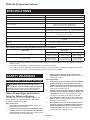 2
2
-
 3
3
-
 4
4
-
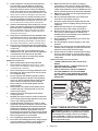 5
5
-
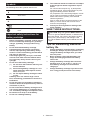 6
6
-
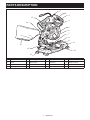 7
7
-
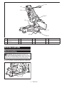 8
8
-
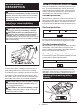 9
9
-
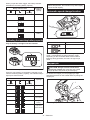 10
10
-
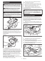 11
11
-
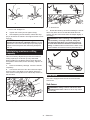 12
12
-
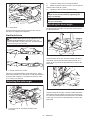 13
13
-
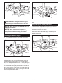 14
14
-
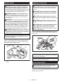 15
15
-
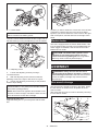 16
16
-
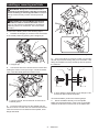 17
17
-
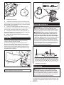 18
18
-
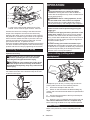 19
19
-
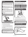 20
20
-
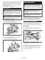 21
21
-
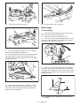 22
22
-
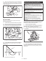 23
23
-
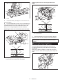 24
24
-
 25
25
-
 26
26
-
 27
27
-
 28
28
-
 29
29
-
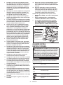 30
30
-
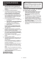 31
31
-
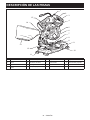 32
32
-
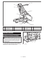 33
33
-
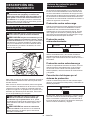 34
34
-
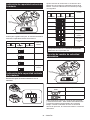 35
35
-
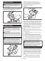 36
36
-
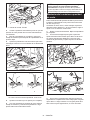 37
37
-
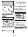 38
38
-
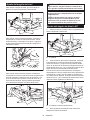 39
39
-
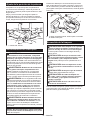 40
40
-
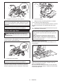 41
41
-
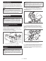 42
42
-
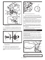 43
43
-
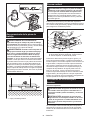 44
44
-
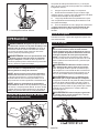 45
45
-
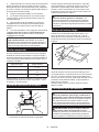 46
46
-
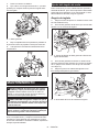 47
47
-
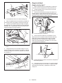 48
48
-
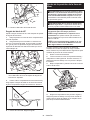 49
49
-
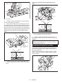 50
50
-
 51
51
-
 52
52


Makita XSL05 Manual de usuario
- Categoría
- Sierras de inglete
- Tipo
- Manual de usuario
- Este manual también es adecuado para
en otros idiomas
- English: Makita XSL05 User manual
Artículos relacionados
-
Makita XSL02Z Manual de usuario
-
Makita LS1018 Guía del usuario
-
-
Makita DLS714 Manual de usuario
-
Makita MLS100 El manual del propietario
-
Makita DLS600 Manual de usuario
-
-
-
-
Otros documentos
-
Stanley FATMAX FME720 Manual de usuario
-
-
Delta S26-272L El manual del propietario
-
Craftsman CMCS714M1 El manual del propietario
-
Stanley FME721 Manual de usuario
-
Stanley SFMCS701 Manual de usuario
-
Black & Decker SMS254 T1 El manual del propietario
-
Ferm MSM1040 Manual de usuario
-
Delta S26-262LS El manual del propietario
-
Black & Decker CS1250KL Manual de usuario