Metal Work BOXI EB 80 4 Position Electro Pneumatic Manifold Base Manual de usuario
- Tipo
- Manual de usuario

= solo un control eléctrico por posición. Utilizable solo con válvulas de un electropiloto tipo V, J, G y R.
Si se instala la falsa válvula (N) o el Bypass (Y) se ocupa una posición eléctrica.
= 2 controles eléctricos por posición. Utilizable para todos los tipos de válvulas. Si se instala la válvula
tipo V, G, J o R (con un electropiloto), la falsa válvula (N) o el Bypass (Y) se ocupan ambas posiciones
eléctricas.
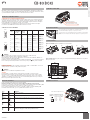
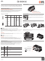
EB 80 BOXI es una base electroneumática de 4 posiciones para válvulas EB 80, disponible en 2 configuraciones,
con 4 u 8 controles para solenoides. Se pueden instalar hasta 4 válvulas con un solenoide en la base de 4 controles,
se pueden instalar hasta 4 válvulas con uno o dos solenoides en la base de 8 controles.
CONEXIONADO DE LA CONEXIÓN ELÉCTRICA MULTIPOLAR
La alimentación y el control de las electroválvulas de la isla se realizan a través de un conector D-Sub de 9 polos
que permite controlar hasta 8 solenoides. Solo se permiten comandos de tipo PNP. No se requiere alimentación
auxiliar fija, la activación de la electrónica de control se realiza mediante cualquier mando de los electropilotos.
Puede ser alimentada con un amplio rango de voltaje, de 12 a 24 VDC.
Cada salida del sistema de control debe proporcionar la potencia necesaria para activar el electro-piloto.
La corriente de cada salidadel sistema de control debe ser de al menos 500 mA.
INSTALACIÓN Y CONEXIONADO ELÉCTRICO
ATENCIÓN
Desconecte la tensión antes de enchufar o desenchufar el conector (riesgo de daño funcional).
Utilice únicamente terminales de válvulas completamente ensamblados.
Para la alimentación, utilice solo fuentes de alimentación de acuerdo con IEC 742 / EN60742 / VDE0551 con
resistencia de aislamiento mínima de 4kV (PELV).
La isla debe conectarse a tierra mediante la conexión, indicada con el símbolo PE (ver “conexión toma de tierra“).
En caso de descargas electrostáticas, la falta de conexión a tierra puede provocar averías y daños irreversibles
VOLTAJE DE SUMINISTRO
El sistema permite un amplio rango de suministro de energía, desde 12VDC - 10% hasta 24VDC + 30% o desde
un voltaje mínimo de 10,8 VDC a un voltaje máximo de 31,2 VDC.
ATENCIÓN
Un voltaje superior a 32 VDC daña irreparablemente el sistema.
CONSUMO
Las electroválvulas se controlan a través de una placa electrónica equipada con un microprocesador.
Para garantizar un funcionamiento seguro de la válvula y reducir el consumo de energía, el control es del tipo
“speed up“, es decir, se suministran 3W al electropiloto durante 15 milisegundos y luego se reduce la potencia
gradualmente a 0.3W. El microprocesador a través de un comando PWM regula la corriente que circula por la
bobina compensando cualquier variación de voltaje.
La isla está protegida contra sobrecargas e inversión de polaridad.
El mando de una salida en presencia de un cortocircuito daña irreparablemente la placa electrónica.
La sobrecarga o el comando de un piloto interrumpido o faltante se indica mediante el parpadeo del LED rojo ERR.
Las alarmas permanentes permanecen activas mientras un comando permanece activo.
En caso de tensión de alimentación fuera de rango, la anomalía se señaliza con la luz fija del LED rojo ERR.
Las válvulas continúan funcionando, pero no se garantiza el funcionamiento correcto.
PROTECCIÓN Y DIAGNÓSTICO
Pilotos Error Significado
OFF OFF La salida no está controlada.
ON (verde) OFF La salida está activa y funciona correctamente.
ON (verde) ROJO
(Parpadeo
T ON 0.1 sec
T OFF 1 sec)
Electropiloto interrumpido o faltante (falsa válvula o válvula con un electropiloto instalada
sobre una base para dos electropilotos).
OFF ROJO
(Parpadeo
T ON 0.4 sec
T OFF 2 sec)
Electropiloto o salida de la base en cortocircuito.
ON (verde) ON (rojo) Tensión de alimentación fuera de rango. menor de 10.8VDC o mayor de 31.2VDC
Attención: un voltaje superior a 32VDC daña irreparablemente el sistema.
TIPO DE DATOS EN LAS BASES
OPCIONES DE FIJACIÓN
CONECTOR D-SUB 9 POLOS PRECABLEADO
Fijación en Carril DIN: fijación en carril DIN en la secuencia indicada.
Fijación mediante patas: las 3 patas se incluyen en cada caja EB 80 BOXI. Empujar firmemente en su alojamiento
hasta que hagan “click”.
CONEXIONADO TOMA DE TIERRA
La toma de tierra siempre va conectada.
Utilizar el tornillo Ø3 incluido con la isla.
Led de señalización diagnóstico
www.metalwork.eu
ALIMENTAZIONE PNEUMATICA - SCARICO SILENZIATOESQUEMA EB 80 BOXI IO-Link
Led de señalización de diagnóstico IO-Link
Conexión a la red EB 80 Boxi IO-Link
BUS IN (Conector macho M12 codificación A)
Port Class A
1 = L+
2 = NC
3 = L-
4 = C/Q
5 = NC
Port Class B
1 = L+
2 = 2L+
3 = L-
4 = C/Q
5 = 2L-
M0060421 ES_EN - IM01 - 03/2022
Posición
contacto
eléctrico
Color conductor
correspondiente
cable Metal Work
conector IP40
Color conductor
correspondiente
(DIN 47100)
conector IP65
Función Base
4
posiciones Base 8 posiciones
1 Verde / Negro
Blanco
Out 1 +
VDC Electropiloto
14
válvula
1
Electropiloto
14
válvula
1
2Blanco
Marrón
Out 2 +
VDC Electropiloto
14
válvula
2
Electropiloto
12
válvula
1
3Azul / Negro
Verde
Out 3 +
VDC Electropiloto
14
válvula
3
Electropiloto
14
válvula
2
4Azul
Amarillo
Out 4 +
VDC Electropiloto
14
válvula
4
Electropiloto
12
válvula
2
5Amarillo / Negro
Gris
Out 5 +
VDC
/
Electropiloto
14
válvula
3
6Amarillo
Rosa
Out 6 +
VDC
/
Electropiloto
12
válvula
3
7Rojo / Negro
Azul
Out 7 +
VDC
/
Electropiloto
14
válvula
4
8Verde
Rojo
Out 8 +
VDC
/
Electropiloto
12
válvula
4
9Blanco / Negro Negro COM 0VDC
Común Común
Macho
Lado ISLA
Hembra
Lado CABLE

www.metalwork.eu
= only one electrical control for each position. Can only be used with valves with one solenoid pilot,
types V, J, G and R. If you use a N dummy or Y bypass valve, it is occupied an electric position.
= 2 electrical controls for each position. It can be used for all types of valves. If you use a V, G, J or
R type valves (with only one solenoid pilot), N dummy or Y
bypass
valve, both electrical positions get
occupied.
The BOXI EB 80 is a 4-position electro-pneumatic manifold base for EB80 valves, available in 2 configurations, with
4 or 8 controls for solenoid pilots. Up to 4 valves with one solenoid pilot can be installed on the manifold base with
4 controls, and up to 4 valves with one or two solenoid pilots can be installed on the manifold base with 8 controls.
CONNECTING UP THE MULTI-POLE ELECTRICAL CONNECTION
The solenoid valves of the island are powered and controlled via a D-Sub 9-pin connector with up to 8 solenoid pilots.
Only PNP pin configuration is allowed. There is no need for an auxiliary power supply, and control electronics can be
actuated by any of the solenoid pilot commands. The power supply voltage can range from 12 to 24 VDC.
Each control system output must supply the amount of power required to actuate the solenoid pilot.
The control system output current must be at least 500 mA.
INSTALLATION AND WIRING CONNECTION
WARNING!
Power off the system before plugging or unplugging the connector (risk of functional damage).
Use fully assembled valve units only.
Only use power packs complying with IEC 742/EN60742/VDE0551 with at least 4kV insulation resistance (PELV).
Earth the module using the connection identified with PE (see grounding connection).
Failure to earth the system properly may cause malfunctions and serious damage in the event of electrostatic
discharge.
SUPPLY VOLTAGE
The system is designed to operate with wide power ratings, ranging from 12VDC -10% to 24VDC +30%, i.e. with a
minimum voltage rating of 10.8VDC and a maximum of 31.2VDC.
WARNING!
Voltage greater than 32VDC will damage the system irreparably.
INPUT CURRENT
Solenoid valves are controlled via an electronic board equipped with a microprocessor.
In order to ensure safe operation of the valve and reduce energy consumption, a “speed-up” control is provided,
i.e. 3W is supplied to solenoid pilot for 15 milliseconds and then power is gradually reduced to 0.25W.
The microprocessor regulates, via a PWM control, the current in the coil by compensating for any voltage variation.
The island is protected against overload and polarity inversion.
In the presence of a short-circuit, the output command causes an irrevocable damage to the electronic board.
The overload or the command of a discontinued or failed control of a solenoid pilot is indicated by the flashing of the
ERR red. The permanent alarms stay on as long as a command remains active.
If the supply voltage is out of range, the fault is indicated by the steady activation of the ERR red LED light.
The valves continue to be operated, but correct operation is not guaranteed.
PROTECTIONS AND DIAGNOSTICS
Pilots Error Meaning
OFF OFF The output is not controlled.
ON (green) OFF The output is active and works properly.
ON (green) RED
(Flashing
T ON 0.1 sec
T OFF 1 sec)
Solenoid pilot interrupted or missing (false valve or valve with solenoid pilot installed on a base
for two solenoid pilots).
OFF RED
(Flashing
T ON 0.4 sec
T OFF 2 sec)
Solenoid pilot or base output short-circuited.
ON (green) ON (red) Supply voltage less than 10.8VDC or greater to 31.2VDC
IMPORTANT! Voltage greater than 32VDC will damage the system irreparably.
TYPE OF DATA IN THE BASES
FIXING OPTIONS
CONNECTOR D-Sub 9 PIN PRE-WIRED
Fixing on a DIN bar: fixing on a DIN bar in the sequence indicated.
Fixing by means of brackets: the 3 brackets are already included in each EB 80 BOXI pack. Push them firmly into
the appropriate seats on the base up to the “click”.
Electric
contact
position
Colour of the
corresponding wire
Metal Work cable
IP40 connector
Colour of the
corresponding wire
(DIN 47100)
IP65 connector
Function 4-position base 8-position base
1 Green/black White Out 1 + VDC Solenoid pilot 14
valve 1 Solenoid pilot 14
valve 1
2White
Brown
Out 2 + VDC Solenoid pilot 14
valve 2 Solenoid pilot 12
valve 1
3Blue/black
Green
Out 3 + VDC Solenoid pilot 14
valve 3 Solenoid pilot 14
valve 2
4Blue
Yellow
Out 4 + VDC Solenoid pilot 14
valve 4 Solenoid pilot 12
valve 2
5Yellow/black
Grey
Out 5 + VDC /Solenoid pilot 14
valve 3
6Yellow
Pink
Out 6 + VDC /Solenoid pilot 12
valve 3
7Red/black
Blue
Out 7 + VDC /Solenoid pilot 14
valve 4
8Green
Red
Out 8 + VDC /Solenoid pilot 12
valve 4
9White/black Black COM 0VDC Common Common
Male
ISLAND side
Female
CABLE side
GROUNDING CONNECTION
The grounding has to be always connected.
Use the Ø3 screw provided with the valve island.
Diagnostic signaling LED
ALIMENTAZIONE PNEUMATICA - SCARICO SILENZIATOEB 80 BOXI IO-Link DIAGRAM
IO-Link diagnostic signaling LED
Connection to the EB 80 IO-Link network
BUS IN (M12 male connector, A encoding)
Port Class A
1 = L+
2 = NC
3 = L-
4 = C/Q
5 = NC
Port Class B
1 = L+
2 = 2L+
3 = L-
4 = C/Q
5 = 2L-
-
 1
1
-
 2
2


Metal Work BOXI EB 80 4 Position Electro Pneumatic Manifold Base Manual de usuario
- Tipo
- Manual de usuario
en otros idiomas
Otros documentos
-
Ross DM2C Operating Instructions Manual
-
AVENTICS Single valve, Series CL03 El manual del propietario
-
Festo CPA-SC-DN Brief description
-
ESAB Precision Plasmarc System Guía de instalación
-
Festo Compact Performance CP-FB6-E Manual de usuario
-
Pleasant Hearth VFF-PH26D Manual de usuario
-
ESAB m3® plasma Water Injection Control Manual de usuario
-
-