P-4 ● P-5 ● P-6 – INSTRUKCJA OBSŁUGI
2
Etykietą z nazwą przyrządu zaznaczono frag-
menty dotyczące specyficznych cech danego
urządzenia. Pozostałe fragmenty tekstu dotyczą
wszystkich innych typów przyrządu.
SPIS TREŚCI
1 Bezpieczeństwo ..........................................3
1.1 Symbole bezpieczeństwa ........................4
1.2 Obostrzenia bezpieczeństwa ...................4
1.3 Porady dotyczące bezpieczeństwa ...............4
2 Opis funkcjonalny .......................................6
2.1 Interfejs ...................................................6
2.2 Wyświetlacz ...............................7
3 Pomiary .......................................................7
3.1 Włączenie testera ....................................7
3.2 Kontrola działania testera ........................7
3.3 Pomiar napięcia 1P .................................8
3.4 Pomiar napięcia 2P .................................9
3.5 Test ciągłości obwodu / test diody ......... 10
3.6 Pomiar z użyciem wewn. impedancji ...... 10
3.6.1 Pomiar napięcia ................................. 11
3.6.2 Test ciągłości obwodu pod napięciem ..... 11
3.6.3 Test zadziałania RCD ........................ 11
3.7 Pomiar rezystancji .................... 11
3.8 Test kolejności faz ................................. 12
3.9 Identyfikacja fazy ............................ 13
3.9.1 Synchronizacja .................................. 13
3.9.2 Odliczanie ......................................... 14
3.9.3 Określenie fazy .................................. 14
3.10 Latarka .................................................. 15
3.11 Podświetlenie wyświetlacza ..... 15
3.12 Zatrzymanie wyniku (funkcja HOLD) ...... 15
4 Wymiana baterii ........................................ 15
5 Czyszczenie i konserwacja ...................... 16
6 Magazynowanie ........................................ 17
7 Rozbiórka i utylizacja ............................... 17
8 Dane techniczne ....................................... 17
9 Producent .................................................. 19
Dziękujemy za zakup naszego dwubiegunowego
testera napięcia. Tester serii P jest nowoczesnym,
wysokiej jakości przyrządem pomiarowym, łatwym
i bezpiecznym w obsłudze. Zapoznanie się z ni-
niejszą instrukcją pozwoli uniknąć błędów przy
pomiarach i zapobiegnie ewentualnym problemom
przy obsłudze przyrządu.
Producent zastrzega sobie prawo wprowa-
dzania zmian w wyglądzie, wyposażeniu i
danych technicznych przyrządu.

P-4 ● P-5 ● P-6 – INSTRUKCJA OBSŁUGI
3
1 Bezpieczeństwo
Wskaźniki napięcia typu P służą do testowania napię-
cia, ciągłości połączeń, sprawdzania diod, kierunku
wirowania faz, jak również – w wybranych modelach –
pomiaru rezystancji oraz identyfikacji faz.
Aby zapewnić odpowiednią obsługę i poprawność
uzyskiwanych wyników, należy przestrzegać poniż-
szych zaleceń.
Przed rozpoczęciem eksploatacji przyrządu nale-
ży dokładnie zapoznać się z niniejszą instrukcją i
zastosować się do przepisów bezpieczeństwa i
zaleceń producenta.
Każde zastosowanie przyrządu inne niż podane w
tej instrukcji może spowodować jego uszkodzenie
i być źródłem poważnego niebezpieczeństwa dla
użytkownika.
Przyrząd powinien być obsługiwany wyłącznie
przez osoby odpowiednio wykwalifikowane, po-
siadające wymagane uprawnienia do przeprowa-
dzania pomiarów w instalacjach elektrycznych.
Posługiwanie się testerem przez osoby nieupraw-
nione może spowodować uszkodzenie przyrządu i
być źródłem poważnego niebezpieczeństwa dla
użytkownika.
Podczas pracy z urządzeniem należy przestrze-
gać przepisów i wymogów bezpieczeństwa obo-
wiązujących w danym kraju. Dotyczy to również
używania środków ochrony osobistej zabezpie-
czających przed porażeniem elektrycznym.
Przed rozpoczęciem użytkowania przyrządu nale-
ży sprawdzić poprawność wskazań na źródle
znanego napięcia.
Nie wolno dokonywać pomiarów w atmosferze
grożącej wybuchem (np. w obecności gazów pal-
nych, oparów, pyłów, itp.). Używanie miernika w
tych warunkach może wywołać iskrzenia i spo-
wodować eksplozję.
Niedopuszczalne jest używanie:
przyrządu, który uległ uszkodzeniu (również
pęknięcia i ubytki obudowy) i jest całkowicie
lub częściowo niesprawny,
przyrządu, którego przewód ma uszkodzoną
izolację,
przyrządu przechowywanego zbyt długo w
złych warunkach (np. zawilgoconego). Po
przeniesieniu testera z otoczenia zimnego do
ciepłego o dużej wilgotności nie wykonywać
pomiarów do czasu ogrzania przyrządu do
temperatury otoczenia (ok. 30 minut).
Nie wolno używać przyrządu z niedomkniętym lub
otwartym pojemnikiem baterii ani zasilać go ze źró-
deł innych niż wymienione w niniejszej instrukcji.
Gdy wskaźnik niskiego poziomu naładowania ba-
terii zaświeci się, wyniki pomiarów mogą być nie-
prawidłowe.
Nie należy wykonywać pomiarów napięcia dłużej
niż 30 s. Po pomiarze trwającym 30 s następny
pomiar można wykonać nie wcześniej niż po
240 s.

P-4 ● P-5 ● P-6 – INSTRUKCJA OBSŁUGI
4
1.1 Symbole bezpieczeństwa
Niniejszy symbol, umieszczony w
pobliżu innego symbolu lub gniazda
wskazuje, że użytkownik winien
zapoznać się z dalszymi informacjami
zamieszczonymi w instrukcji obsługi.
Niniejszy symbol, umieszczony w
pobliżu gniazda wskazuje, że w
warunkach normalnego użytkowania
istnieje możliwość wystąpienia
niebezpiecznych napięć.
II klasa ochronności – izolacja podwójna
Niniejszy symbol oznacza, że
urządzenia nie wolno wyrzucać do
zwykłych pojemników na odpady, tylko
do wyznaczonego punktu zbiórki
odpadów elektronicznych.
Przyrząd spełnia wymogi prawne Unii
Europejskiej.
CAT Kategoria pomiarowa przyrządu.
1.2 Obostrzenia bezpieczeństwa
Różne sygnały wskazujące detektora napięcia
(w tym wskazanie napięć granicznych ELV) nie
mogą być używane do celów pomiarowych.
Napięcia oznaczone na wykrywaczu napięcia
to napięcia znamionowe lub nominalne zakre-
sy napięcia.
Tester napięcia może być używany tylko w in-
stalacjach o określonych napięciach nominal-
nych lub nominalnych zakresach napięcia.
Rzeczywistą wartość pomiaru można
określić za pomocą wyświetlacza LCD.
Przed użyciem wykrywacza napięcia ze
wskaźnikiem dźwiękowym w miejscach o wy-
sokim poziomie szumu tła należy określić, czy
sygnał dźwiękowy jest słyszalny.
1.3 Porady dotyczące bezpieczeństwa
W zależności od wewnętrznej impedancji wskaźni-
ka napięcia, w razie wystąpienia napięcia zakłóca-
jącego istnieją różne możliwości wskazania statu-
su „występuje napięcie robocze” lub „nie występuje
napięcie robocze”.

P-4 ● P-5 ● P-6 – INSTRUKCJA OBSŁUGI
5
Małooporowy wskaźnik napięcia (impedancja
<100 kΩ). Napięcie zakłócające jest tłumione lub
obniżane.
W porównaniu z wartością referencyjną
100 kΩ wskaźnik napięcia ze stosunkowo ni-
ską impedancją wewnętrzną nie wskaże
wszystkich wartości napięcia zakłócającego
przy wartości pierwotnej powyżej
50 V AC / 120 V DC. Przy kontakcie z testo-
wanymi obiektami wskaźnik napięcia może
tymczasowo obniżyć wartości napięcia zakłó-
cającego poprzez rozładowanie do poziomu
poniżej ww. wartości. Jednakże po usunięciu
wskaźnika napięcie zakłócające ponownie
wzrośnie do pierwotnej wartości.
Jeśli nie pojawia się wskazanie „występuje na-
pięcie“, przed rozpoczęciem prac zdecy-
dowanie zaleca się zastosowanie urządzenia
uziemiającego.
Wielkooporowy wskaźnik napięcia (impedancja
>100 kΩ). Napięcie zakłócające nie jest tłumione
ani obniżane.
W porównaniu z wartością referencyjną
100 kΩ, przy występowaniu napięcia zakłóca-
jącego wskaźnik napięcia ze stosunkowo wy-
soką impedancją wewnętrzną nie wskaże jed-
noznacznie statusu „nie występuje napięcie
robocze”.
Jeśli wskazanie „występuje napięcie” pojawia
się przy obiekcie, który jest odłączony od in-
stalacji, zdecydowanie zaleca się poprzez wy-
konanie dodatkowych czynności (np.: zasto-
sowanie odpowiedniego wskaźnika napięcia,
który umożliwia rozróżnienie napięcia robo-
czego od napięcia zakłócającego, kontrola
wzrokowa miejsca odłączenia w sieci elek-
trycznej itp.) w celu potwierdzenia statusu „nie
występuje napięcie robocze” testowanego
obiektu i stwierdzenie, że napięcie wskazywa-
ne przez wskaźnik jest napięciem zakłócają-
cym.
Wskaźniki napięcia, które umożliwiają rozróż-
nienie napięcia roboczego od napięcia zakłóca-
jącego. Wskaźnik napięcia z opcją wskazania
dwóch wartości wewnętrznej impedancji uzyskał
pozytywny wynik kontroli wykonania/konstrukcji w
zakresie obsługi napięcia zakłócającego i umożli-
wia (w ramach granic technicznych) rozróżnienie
napięcia roboczego i napięcia zakłócającego oraz
bezpośrednie lub pośrednie sprawdzenie typu wy-
stępującego napięcia.

P-4 ● P-5 ● P-6 – INSTRUKCJA OBSŁUGI
6
2 Opis funkcjonalny
2.1 Interfejs
Pojemnik ochronny końcówek sond po-
miarowych
Sonda pomiarowa L1/-
Sonda pomiarowa L2/+
Końcówki sond L1 i L2
Kontrolka obecności napięcia przemien-
nego
Kontrolki polaryzacji napięcia stałego
Kontrolki zgodności faz
faza zgodna
faza odwrotna
Kontrolki funkcyjne
Wskaźnik ciągłości (R < 400 kΩ)
Test diody
Kontrolka testu RCD
Przycisk wyzwalania testu RCD sondy L1
Przycisk wyzwalania testu RCD sondy L2
Dioda LED oświetlająca punkt pomiarowy
Linijka diodowa
Wskazanie przybliżonej wartości napięcia
Kontrolka:
stanu baterii
pomiaru rezystancji
Sygnalizacja napięcia niebezpiecznego
(>50 V AC lub 120 V DC)
Wyświetlacz LCD z odczytem oraz sym-
bolami
Przycisk funkcyjny
Oświetlenia punktu pomiarowego i pod-
świetlenia ekranu (nacisnąć krótko)
Włączenie trybu uzgadniania faz (nacisnąć
i przytrzymać przez 2 s)
Przycisk HOLD
Zatrzymanie odczytu na wyświetlaczu
(nacisnąć krótko)
Powrót do pomiaru ciągłego (nacisnąć
krótko)
Włączenie pomiaru rezystancji (nacisnąć
długo (2 s))

P-4 ● P-5 ● P-6 – INSTRUKCJA OBSŁUGI
7
2.2 Wyświetlacz
Pole odczytowe
Odczyt zatrzymany na ekranie (funkcja
HOLD)
Kolejność faz zgodna
Kolejność faz odwrotna
Niski poziom naładowania baterii
Jednostki wyświetlanych wielkości
3 Pomiary
3.1 Włączenie testera
W celu włączenia testera:
zetknąć ze sobą metalowe końcówki sond
pomiarowych
lub
podłączyć końcówki sond do źródła napięcia o
wartości ≥6 V AC/DC.
3.2 Kontrola działania testera
Przed i po każdym użyciu testera należy przepro-
wadzić kontrolę jego działania:
zewrzeć ze sobą metalowe końcówki sond
pomiarowych w czasie ok. 4-6 s, a następnie
je rozewrzeć. Wówczas powinny:
zaświecić się wszystkie diody,
zabrzęczeć brzęczyk,
zaświecić się wszystkie ikony i
podświetlenie wyświetlacza.
Ponadto przed każdym użyciem należy spraw-
dzić tester mierząc znane źródło napięcia.
Funkcja wskazywania napięcia niebez-
piecznego jest aktywna przy wyładowanych
bateriach lub bez nich. Do działania pozo-
stałych funkcji wymagane są sprawne
baterie.

P-4 ● P-5 ● P-6 – INSTRUKCJA OBSŁUGI
8
3.3 Pomiar napięcia 1P
Mocno chwycić sondę L2 w
obszarze pomiędzy przewo-
dem a barierą ochronną.
Podłączyć sondę L2 testera
do badanego obiektu.
Obecność napięcia przemien-
nego jest sygnalizowana za
pomocą świecenia kontrolek.
kontrolka napięcia prze-
miennego.
Po odłączeniu od napięcia te-
ster wyłącza się po kilku se-
kundach.
Przy jednobiegunowym określaniu faz do
oznaczania przewodów zewnętrznych w
pewnych warunkach może nastąpić po-
gorszenie pracy testera (np. przy stoso-
waniu izolowanych środków ochrony oso-
bistej lub izolacji stanowiska).
Jednobiegunowe testowanie fazy nie mo-
że być wystarczającym środkiem do
określenia, czy obwód znajduje się pod
napięciem. Należy posłużyć się testem
napięcia 2P.
Podczas pracy w tym trybie funkcja sa-
moczynnego wyłączenia testera jest nie-
aktywna.
Wykonanie pomiaru możliwe jest w ręka-
wicach ochronnych bez stosowania elek-
trody dotykowej.

P-4 ● P-5 ● P-6 – INSTRUKCJA OBSŁUGI
9
3.4 Pomiar napięcia 2P
Podłączyć obie sondy te-
stera do układu pod napię-
ciem.
Urządzenie włączy się
automatycznie po wy-
kryciu napięcia o warto-
ści powyżej 6 V.
Wyświetlacz LCD włą-
czy się od wartości oko-
ło 6 V.
Napięcie jest wskazywane
przez:
7-stopniową linijkę dio-
dową,
wyświetlacz .
Po odłączeniu od napięcia
tester wyłącza się z opóź-
nieniem kilku sekund.
Obecność napięcia jest sy-
gnalizowana sygnałem
dźwiękowym i świeceniem
kontrolek.
napięcie przemienne
napięcie stałe, sonda L2
podłączona do bieguna
dodatniego +
napięcie stałe, sonda L2
podłączona do bieguna
ujemnego –
wykryto napięcie niebez-
pieczne
Wyświetlacz LCD jest aktywny
wyłącznie przy sprawnych bateriach.
Podczas pracy w tym trybie funkcja sa-
moczynnego wyłączenia testera jest nie-
aktywna.
Rzeczywista wartość napięcia może być
określona tylko w modelach z wyświetla-
czem LCD.
Sygnał dźwiękowy działa tylko przy
sprawnych bateriach.

P-4 ● P-5 ● P-6 – INSTRUKCJA OBSŁUGI
10
3.5 Test ciągłości obwodu / test
diody
UWAGA!
Obiekt badany nie może być pod napię-
ciem.
Podłączyć obie sondy do badanego obiektu.
Sygnalizacja ciągłości za pomocą sygnału dźwię-
kowego oraz świecenia kontrolek:
,
na wyświetlaczu .
Po odłączeniu od obiektu tester wyłącza się z
kilkusekundowym opóźnieniem.
Maksymalna rezystancja mierzonego
obiektu: 400 kΩ.
Jeśli tester wykryje napięcie ≥6 V, przełą-
cza się automatycznie w tryb pomiaru na-
pięcia (rozdz. 3.3, 3.4).
Podczas pracy w tym trybie funkcja sa-
moczynnego wyłączenia testera jest nie-
aktywna.
3.6 Pomiar z użyciem wewn.
impedancji
Tester wyposażony jest w dodatkową, niewielką
impedancję, sprzęgniętą z silniczkiem wibracyj-
nym.

P-4 ● P-5 ● P-6 – INSTRUKCJA OBSŁUGI
11
Aby przeprowadzić test wyłącznika różnicowoprą-
dowego należy:
podłączyć sondy pomiarowe do badanego ob-
wodu,
nacisnąć i przytrzymać jednocześnie przyciski
. W konsekwencji:
silniczek wibracyjny zawibruje po podaniu
nań napięcia (ok. 200 V),
zaświeci się kontrolka .
Naciśnięcie tylko jednego przycisku wyzwa-
lającego lub nie spowoduje wyzwo-
lenia wyłącznika różnicowoprądowego.
3.6.1 Pomiar napięcia
Włączenie w mierzony obwód niewielkiej impe-
dancji redukuje napięcia zakłóceniowe o charak-
terze pojemnościowym i indukcyjnym.
3.6.2 Test ciągłości obwodu pod napięciem
Uaktywnienie się silniczka wibracyjnego potwier-
dza ciągłość badanego obwodu.
3.6.3 Test zadziałania RCD
Test polega na wymuszeniu między fazą L a linią
PE prądu różnicowego, przekraczającego prąd za-
działania wyłącznika.
3.7 Pomiar rezystancji
UWAGA!
Obiekt badany nie może być pod napię-
ciem.
Nacisnąć przycisk ponad 2 sekundy, aby
wybrać funkcję pomiaru rezystancji – zaświeci
się kontrolka .
Końcówki sond pomiarowych przyłożyć do za-
cisków badanego obiektu.
Odczytać z wyświetlacza wartość rezystancji.

P-4 ● P-5 ● P-6 – INSTRUKCJA OBSŁUGI
12
Funkcja aktywna tylko przy sprawnych ba-
teriach.
Jeśli końcówki sond pomiarowych są
rozwarte lub wartość mierzona przekracza
zakres pomiarowy, wyświetla się wartość
OL.
Jeśli podczas pomiaru rezystancji tester
wykryje napięcie niebezpieczne, to dodat-
kowo zaświeci się kontrolka napięcia nie-
bezpiecznego.
Podczas pracy w tym trybie funkcja sa-
moczynnego wyłączenia testera jest nie-
aktywna.
3.8 Test kolejności faz
Podłączyć końcówkę sondy:
L1 do domniemanej fazy L1,
L2 do domniemanej fazy L2.
Chwycić mocno obie sondy L1
i L2 (uzyskanie sprzężenia po-
jemnościowego z ziemią).
Wartość napięcia międzyfa-
zowego wskazywana jest
przez:
linijkę diodową,
wyświetlacz .
Sygnalizacja kolejności faz po-
przez zaświecenie:
kontrolek,
ikon na wyświetlaczu
.
Opis kontrolek
kolejność zgodna
(faza L1 wyprzedza L2)
kolejność przeciwna
(faza L2 wyprzedza L1)
Po zamianie sond świeci
symbol przeciwny.
Funkcja aktywna tylko przy sprawnych ba-
teriach.
Pomiar można wykonywać również w rę-
kawicach – trzeci biegun sprzężony jest
pojemnościowo z sondą pomiarową L2
trzymanym przez użytkownika.
Kontrolki diodowe i symbole wyświetlaczu
L i R działają tylko w pomiarach napięcia
przemiennego, lecz kolejność faz może
być wyznaczana tylko w układach trójfa-
zowych

P-4 ● P-5 ● P-6 – INSTRUKCJA OBSŁUGI
13
3.9 Identyfikacja fazy
Funkcja umożliwia identyfikację faz napięcia w
dwóch odległych od siebie punktach instalacji.
Aby uruchomić funkcję, nacisnąć i przytrzymać
przycisk przez >2 s. Na wyświetlaczu po-
jawi się komunikat 123.
Użytkownik ma 30 sekund na rozpoczęcie
procesu synchronizacji. W przeciwnym razie
po tym czasie urządzenie wyłączy się.
Wyjście z funkcji poprzez naciśnięcie i przy-
trzymanie przycisku przez 2 s.
W trybie uzgadniania faz funkcja HOLD jest
nieaktywna.
3.9.1 Synchronizacja
Punkt odniesienia
Gotowość do syn-
chronizacji jest sy-
gnalizowana odczy-
tem:
oraz pulsacją kon-
trolki .
Podłączyć tester do
badanego obiektu
(podłączenie
sond: najpierw N,
następnie L).
Wewnętrzny gene-
rator testera syn-
chronizuje się z fa-
zą, do której jest
podłączony (okres i
faza mają być
zgodne z okresem i
fazą sygnału na za-
ciskach).
Proces synchronizacji sygnalizowany jest odczytem:
Fakt dokonania synchronizacji jest sygnalizo-
wany przez:
powtarzający się sygnał dźwiękowy w przy-
padku obecności napięcia,
kontrolki oraz wskazania wyświetlacza:

P-4 ● P-5 ● P-6 – INSTRUKCJA OBSŁUGI
14
3.9.2 Odliczanie
Po dokonaniu synchronizacji i odłączeniu od
punktu odniesienia tester zaczyna odmierzać
upływający czas, określający zmniejszające
się prawdopodobieństwo poprawnego określe-
nia fazy – od 20 do 0 s.
Jeśli przed upływem tego czasu użytkownik
nie podłączy wskaźnika do kolejnego punktu,
to wskaźnik wyłącza się.
3.9.3 Określenie fazy
Punkt określenia fazy
W ciągu 20 s (czas
odliczania) przenieść
tester do badanego
punktu.
Podłączyć tester
(podłączenie sond
zgodne z polaryzacją
podczas synchroni-
zacji – najpierw N,
następnie L).
Miernik przechodzi w
tryb odliczania
(rozdz. 3.9.2).
Opis komunikatów:
Faza zgodna z fazą
odniesienia (przesu-
nięcie fazy <60)
Faza wyprzedza fazę
odniesienia
Faza opóźniona wzglę-
dem fazy odniesienia
Jeżeli tester zostanie odłączony od napięcia
przed zakończeniem synchronizacji:
wyświetla się symbol ,
nadany zostaje sygnał dźwiękowy (czas
trwania 2 s).

P-4 ● P-5 ● P-6 – INSTRUKCJA OBSŁUGI
15
3.10 Latarka
Tester posiada możliwość oświetlenia miejsca
pomiaru,
Nacisnąć krótko przycisk na sondzie po-
miarowej L2.
Wyłączenie funkcji:
po ponownym naciśnięciu przycisku ,
po upłynięciu czasu do automatycznego
wyłączenia przyrządu.
3.11 Podświetlenie wyświetlacza
Tester posiada możliwość podświetlenia wyświe-
tlacza.
Podświetlenie włącza się automatycznie wraz
z włączeniem latarki lub funkcji pomiarowej.
Nacisnąć i przytrzymać przycisk długo na
sondzie pomiarowej L2 w celu wyłączenia
podświetlenia ekranu.
Wyłączenie funkcji następuje również po upły-
nięciu czasu do automatycznego wyłączenia
przyrządu.
3.12 Zatrzymanie wyniku (funkcja
HOLD)
Wskaźniki napięcia mają możliwość za-
trzymania wskazania wyniku pomiarowego napię-
cia lub rezystancji – funkcja HOLD.
Aby zatrzymać wynik, należy nacisnąć krót-
ko przycisk - na wyświetlaczu pojawi się
napis HOLD.
Wyłącznie zatrzymania wyniku na wyświetla-
czu następuje po ponownym krótkim naciśnię-
ciu przycisku .
4 Wymiana baterii
Tester jest zasilany z dwóch baterii LR03 AAA
1,5 V. Konieczność wymiany baterii jest sygnali-
zowana przez:
brak sygnału dźwiękowego po zetknięciu ze
sobą obu końcówek sond pomiarowych,
zbyt słabe świecenie oświetlenia po wciśnięciu
przycisku ,
zaświecenie się kontrolki baterii ,
wyświetlenie symbolu .

P-4 ● P-5 ● P-6 – INSTRUKCJA OBSŁUGI
16
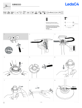
Aby wymienić baterie, należy:
odłączyć sondy pomiarowe od ob-
wodu pomiarowego,
przy pomocy narzędzia lub monety
odkręcić pojemnik baterii w kierun-
ku przeciwnym do ruchu wskazó-
wek zegara,
wyjąć pojemnik,
wymienić baterie przestrzegając
właściwej biegunowości,
włożyć pojemnik i przekręcić go
zgodnie z ruchem wskazówek ze-
gara.
Po zmianie baterii należy wykonać
kontrolę działania urządzenia opisaną
w rozdz. 3.2.
5 Czyszczenie i konserwacja
1. MIERNIK MUSI BYĆ SUCHY. Zawilgocony
miernik należy wytrzeć.
2. MIERNIK NALEŻY STOSOWAĆ ORAZ
PRZECHOWYWAĆ W NORMALNYCH
TEMPERATURACH. Temperatury skrajne
mogą skrócić żywotność elektronicznych
elementów miernika oraz zniekształcić lub
stopić elementy plastikowe.
3. Z MIERNIKIEM NALEŻY OBCHODZIĆ SIĘ
OSTROŻNIE I DELIKATNIE. Upadek miernika
może spowodować uszkodzenie
elektronicznych elementów lub obudowy.
4. MIERNIK MUSI BYĆ UTRZYMYWANY W
CZYSTOŚCI. Od czasu do czasu należy
przetrzeć jego obudowę wilgotną tkaniną. NIE
wolno stosować środków chemicznych,
rozpuszczalników ani detergentów.
5. NALEŻY STOSOWAĆ WYŁĄCZNIE NOWE
BATERIE ZALECANEGO ROZMIARU I
TYPU. Wyjąć z miernika stare lub wyczerpane
baterie, aby uniknąć wycieku elektrolitu i
uszkodzenia urządzenia.
6. JEŻELI MIERNIK MA BYĆ
PRZECHOWYWANY DŁUŻEJ NIŻ 60 DNI,
należy wyjąć z niego baterie i trzymać je
oddzielnie.
Układ elektroniczny miernika nie wymaga
konserwacji.

P-4 ● P-5 ● P-6 – INSTRUKCJA OBSŁUGI
17
6 Magazynowanie
Przy przechowywaniu przyrządu należy przestrzegać
poniższych zaleceń:
założyć na sondy pojemnik ochronny,
upewnić się, że miernik i akcesoria są suche,
przy dłuższym okresie przechowywania należy
wyjąć baterie.
7 Rozbiórka i utylizacja
Zużyty sprzęt elektryczny i elektroniczny należy gro-
madzić selektywnie, tj. nie umieszczać z odpadami
innego rodzaju.
Zużyty sprzęt elektroniczny należy przekazać do
punktu zbiórki zgodnie z Ustawą o zużytym sprzęcie
elektrycznym i elektronicznym.
Przed przekazaniem sprzętu do punktu zbiórki nie na-
leży samodzielnie demontować żadnych części z tego
sprzętu.
Należy przestrzegać lokalnych przepisów dotyczących
wyrzucania opakowań, zużytych baterii i akumulatorów.
8 Dane techniczne
„w.w.” w określeniu dokładności oznacza wyświetlaną
wartość
Urządzenie nie posiada charakteru wzorca i dlatego
nie podlega wzorcowaniu. Właściwą formą kontroli dla
tego typu przyrządów jest sprawdzenie.
Wskazanie napięć
Zakres
Rozdzielczość
Dokładność
12…1000 V
AC/DC
± 12 V, 24 V,
50 V, 120 V,
230 V, 400 V,
≥690 V
Zgodna z
PN-EN 61243-2:2014
Pomiar napięć stałych
Dodatkowo napięcia wskazywane są na linijce
diodowej dla wartości: 12, 24, 50, 120, 230, 400,
≥690 V wraz z sygnalizacją polaryzacji napięcia
(świeci się dioda „+” lub „-”).
Rezystancja wejściowa
Uwe
Rwe
12 V, 24 V, 50 V
ok. 300 kΩ
120 V
230 V
400 V
690 V
Zakres
Rozdzielczość
Dokładność
-49,9…-6,0 V
6,0…49,9 V
0,1 V
±(3% w.w. + 5 cyfr)
-1000…-50 V
50…1000 V
1 V

P-4 ● P-5 ● P-6 – INSTRUKCJA OBSŁUGI
18
Pomiar napięć przemiennych w zakresie
16…400 Hz
Dodatkowo napięcia wskazywane są na linijce
diodowej dla wartości: 12, 24, 50, 120, 230,
400, ≥690 V wraz z sygnalizacją obecności
napięcia przemiennego (świeci się kontrolka
AC).
Częstotliwość napięcia pomiarowego dla linijki:
16…400 Hz.
Pomiar rezystancji
Zakres
Rozdzielczość
Dokładność
0…1999 Ω
1 Ω
±(5% w.w. + 10 cyfr)
Deklarowana dokładność przy 20°C.
Współczynnik temperaturowy ±5 cyfr / 10 K.
Pozostałe dane
a) kategoria pomiarowa wg PN-EN 61010-1 ......... III 1000 V
.............................................................................. IV 600 V
b) stopień ochr. obudowy wg PN-EN 60529 .................. IP65
c) stopień zanieczyszczenia................................................. 2
d) rodzaj izolacji wg PN-EN 61010-1 ........ podwójna, klasa II
e) zasilanie miernika ...............................................................
........................................................... 2 x LR03 AAA 1,5 V
................................................ zalecane ogniwa alkaliczne
f) dokładność wskazań napięcia ........... wg PN-EN 61243-3
g) zakres częstotliwości pracy ............................. 16…400 Hz
h) czas odpowiedzi .......................................................... ≤1 s
i) min. czas przerwy po załączeniu na 30 s ................. 240 s
j) test ciągłości ......................................................................
▪ prąd pomiarowy .................................................. 1,25 μA
▪ zakres ....................................................... 400…500 kΩ
▪ sygnał świetlny i dźwiękowy .................. dla R ≤ 400 kΩ
▪ dokładność progu zadziałania .............................. ±50%
k) zakres pomiaru rezystancji .............. 1…1999 Ω
l) impedancja wejściowa .......................................................
▪ podstawowa ................................................... ok. 300 kΩ
▪ przy dodatkowym obciążeniu ............................ ok. 7 kΩ
m) maksymalny prąd ............................................ IS < 200 mA
n) zakres dla jednobiegunowego wskaźnika fazy .................
▪ napięcie ............................................... 100…1000 V AC
▪ częstotliwość ................................................. 50…400 Hz
▪ sygnalizacja dźwiękowa ............................. Upom > 100 V
o) zakres dla dwubiegunowego wskaźn. kolejności faz
▪ napięcie ...................................................... 100…1000 V
▪ częstotliwość ................................................... 50…60 Hz
p) minimalne napięcie włączenia ....................... ±6 V AC/DC
q) wskazanie przekroczenia zakresu .................... symbol OL
r) wskazanie rozładowania baterii / . /
s) temperatura pracy ........................................... -15...+55C
t) temperatura przechowywania ......................... -20...+70C
u) max. wilgotność ........................................................... 95%
v) max. wysokość pracy ............................................. 2000 m
Zakres
Rozdzielczość
Dokładność
6,0...49,9 V
0,1 V
±(3% w.w. + 5 cyfr)
50...1000 V
1 V

P-4 ● P-5 ● P-6 – INSTRUKCJA OBSŁUGI
19
w) czas do automatycznego wyłączenia ......................... 10 s
.................................................................30 s (tryb HOLD)
.................................................. 600 s (pomiar rezystancji)
x) wyświetlacz.........................................................................
...................................................................... LCD 3½ cyfry
.................................. odczyt 1999 ze wskaźnikami funkcji
y) wymiary ................................................. 275 x 82 x 36 mm
z) masa testera ......................................................................
▪ z bateriami ............................................................. 291 g
▪ bez baterii .............................................................. 267 g
aa) kompatybilność elektromagnetyczna wg wymagań norm
....................................................................... IEC 61326-1
.................................................................... IEC 61326-2-2
bb) zgodność z wymaganiami norm ........................................
....................................................................... IEC 61010-1
....................................................................... IEC 61243-3
cc) standard jakości .................................................. ISO 9001
9 Producent
Producentem przyrządu prowadzącym serwis gwa-
rancyjny i pogwarancyjny jest:
SONEL S.A.
ul. Wokulskiego 11
58-100 Świdnica
tel. +48 74 884 10 53 (Biuro Obsługi Klienta)
e-mail: [email protected]
internet: www.sonel.pl
UWAGA!
Do prowadzenia napraw serwisowych upo-
ważniony jest jedynie producent.
Wyprodukowano w Chińskiej Republice Ludowej
na zlecenie SONEL S.A.


P-4 ● P-5 ● P-6 – USER MANUAL
21
The label with the name of the device indi-
cates fragments concerning specific features of
the device. Other parts of the text apply to all other
types of the device.
CONTENTS
1 Safety ......................................................... 22
1.1 Safety symbols ...................................... 23
1.2 Safety restrictions .................................. 23
1.3 Safety advices ....................................... 23
2 Functional description ............................. 25
2.1 Interface ................................................ 25
2.2 Display ..................................... 26
3 Measurements........................................... 26
3.1 Switching the tester ON ......................... 26
3.2 Operational check of the tester .............. 26
3.3 Voltage measurement 1P ...................... 27
3.4 Voltage measurement 2P ...................... 28
3.5 Circuit continuity test / diode test ........... 29
3.6 Measuring with the internal impedance .. 29
3.6.1 Voltage measurement ....................... 30
3.6.2 Circuit continuity test under voltage ......... 30
3.6.3 RCD test ........................................... 30
3.7 Measurement of resistance .......... 30
3.8 Phase sequence test ............................. 31
3.9 Phase identification ......................... 32
3.9.1 Synchronization ................................. 32
3.9.2 Countdown ........................................ 33
3.9.3 Determining the phase ...................... 33
3.10 Flashlight ............................................... 34
3.11 Display backlight ...................... 34
3.12 'Freezing' the result (HOLD function) ..... 34
4 Replacing batteries ................................... 34
5 Cleaning and maintenance ...................... 35
6 Storage ...................................................... 36
7 Dismantling and disposal ........................ 36
8 Technical specifications .......................... 36
9 Manufacturer ............................................. 38
Thank you for purchasing our two-pole voltage
tester. This tester of P series is a modern, easy
and safe measuring device. Please acquaint your-
self with this manual in order to avoid measuring
errors and prevent possible problems in operation
of the device.
The manufacturer reserves the right to in-
troduce changes in the design, accessories
and technical data of the device.

P-4 ● P-5 ● P-6 – USER MANUAL
22
1 Safety
Voltage testers of P type are used to test voltage,
continuity of connections, diode tests, checking
phase rotation, and - in some models - resistance
measurements and identification of phases.
In order to provide conditions for correct operation
and the correctness of the obtained results, the fol-
lowing recommendations must be observed.
Before you proceed to operate the device, ac-
quaint yourself thoroughly with this manual and
observe the safety regulations and specifications
defined by the producer
Any application that differs from those specified
in the present manual may result in a damage to
the device and constitute a source of danger for
the user.
The device should be operated only by suitably
qualified persons having the necessary permis-
sions to carry out measurements on electrical
systems. Unauthorized use of the tester may re-
sult in its damage and may be a source of seri-
ous hazard to the user.
Comply with safety requirements and regulations
in force in your country when working with the de-
vice. This also applies to the use of personal pro-
tective equipment to protect against electric
shock.
Before using the device, please check its accura-
cy on the known voltage source.
Do not perform measurements in explosive at-
mosphere (e.g. in the presence of flammable
gases, vapours, dusts, etc.). Using the meter in
such conditions may result in sparking and cause
an explosion.
It is unacceptable to operate the device when:
it is damaged (including cracks and missing
parts of the housing) and completely or par-
tially out of order,
its cable insulation is damaged,
it was stored for an excessive period of time
in disadvantageous conditions (e.g. exces-
sive humidity)After moving the device from
a cool to a warm place with a high level of
relative humidity, do not start measure-
ments until the device is warmed up to the
ambient temperature (approximately 30
minutes)
Do not use the tester when the battery compart-
ment is removed or open. Do not power the me-
ter from other sources than those mentioned in
this manual.
When the low battery indicator lights up, test re-
sults may be incorrect.
Do not perform voltage measurements for longer
than 30 seconds. After the measurement period
of 30 s, the next measurement may be made no
earlier than after 240 s.

P-4 ● P-5 ● P-6 – USER MANUAL
23
1.1 Safety symbols
This symbol located near another
symbol or terminal, indicates that the
user should read the further information
contained in the manual.
This symbol located near the terminal,
indicates that in normal use there is a
possibility of dangerous voltages.
Protection class II - double insulation
This symbol indicates that the device
must not be disposed of into any
household waste containers, but must
be provided to a designated collection
point for electronic waste.
The device meets the legal requirements
of the European Union.
CAT Measurement category of the instrument.
1.2 Safety restrictions
The different indicating signals of the voltage
detector (including the ELV limit indication) are
not to be used for measuring purposes.
The voltages marked on the voltage detector
are nominal voltages or nominal voltage rang-
es.
The voltage detector is only to be used on in-
stallations with the specified nominal voltages
or nominal voltage ranges.
The actual measurement value can
be determined using the LCD display.
Before using a voltage detector with audible
indicator at locations with a high background
noise level, it has to be determined whether
the audible signal is perceptible.
1.3 Safety advices
Depending on the internal impedance of the volt-
age detector, in case of presence of interference
voltage there will be a different capability of indi-
cating the presence or absence of operating volt-
age.
Low-impedance voltage tester (impedance
<100 kΩ). Interference voltage is suppressed or
reduced.

P-4 ● P-5 ● P-6 – USER MANUAL
24
A voltage tester of relatively low internal im-
pedance, compared to the reference value of
100 kΩ, will not indicate all interference volt-
ages having an original voltage value above
50 V AC / 120 V DC. When in contact with the
objects to be tested, the voltage tester may
discharge temporarily the interference voltage
to a level below the value mentioned above.
However it will be back to the original value
when the voltage tester is removed.
When the indication “voltage present” does not
appear, it is highly recommended to install
earthing equipment before starting work.
High-impedance voltage tester (impedance
>100 kΩ). Interference voltage will not be sup-
pressed or reduced.
A voltage tester of relatively high internal im-
pedance, compared to the reference value of
100 kΩ, may not permit to clearly indicate the
absence of operating voltage in case of pres-
ence of interference voltage.
When the indication “voltage present” appears
on a part that is expected to be disconnected
from the installation, it is highly recommended
to confirm by another means (e.g. use of an
adequate voltage tester capable of distinguish-
ing between operating voltages and interfer-
ence voltages, visual inspection of the discon-
necting point of the electric circuit, etc.) that
there is no operating voltage on the part to be
tested and to conclude that the voltage indi-
cated by the voltage tester is an interference
voltage.
Voltage testers capable of distinguishing be-
tween operating voltage and interference volt-
age by means of load connection. A voltage
tester stating two values of internal impedance has
passed a performance test of managing interfer-
ence voltages and is (within technical limits) able
to distinguish operating voltage from interference
voltage and has a means to directly or indirectly
indicate which type of voltage is present.

P-4 ● P-5 ● P-6 – USER MANUAL
25
2 Functional description
2.1 Interface
The protective case for tips of test probes
Test probe L1/-
Test probe L2/+
Tips of test probes L1 and L2
AC voltage indicator light
Indicator lights of DC voltage polarization
Indicator lights for direction of phases
clockwise sequence [Right]
counter-clockwise sequence [Left]
Functional indicator lights
Continuity indicator (R <400 kΩ)
Diode test
Indicator lights of RCD test
Button triggering the RCD test of L1 probe
Button triggering the RCD test of L2 probe
LED illuminating the measuring point
LED scale
Indicating the approximate voltage value
Indicator light:
battery status
resistance measurement
Signalling hazardous voltage (>50 V AC
or 120 V DC)
LCD with read-outs and symbols
Function button
Illumination of the measuring point and
display backlight (press shortly)
Activation of the phasing mode (press and
hold for 2 s)
HOLD button
Freezing the measurement results on the
display (press shortly)
Return to continuous measurement (press
shortly)
Activating the resistance measurement
(long press (2 s))

P-4 ● P-5 ● P-6 – USER MANUAL
26
2.2 Display
Reading field
Read-out stopped on the display (HOLD
function)
Clockwise sequence of phases
Counter-clockwise sequence of phases
Low battery status
Units of displayed values
3 Measurements
3.1 Switching the tester ON
To switch the tester ON:
contact the metal tips of test probes with
each other
or
connect the tips of probes to the voltage
source of ≥6 V AC / DC.
3.2 Operational check of the tester
Before and after each use of the tester, check its
operation:
contact the metal tips of test probes with
each other for approx. 4-6 s and then discon-
nect them. This should result in the following:
all the LEDs light up,
the buzzer is activated
all the icons light up and the dis-
play backlight is active.
In addition, before each use, check the tester
by measuring a known voltage source.
The function of indicating dangerous volt-
age source is active with discharged or re-
moved batteries. To operate other functions
efficient batteries are required.

P-4 ● P-5 ● P-6 – USER MANUAL
27
3.3 Voltage measurement 1P
Firmly grasp L2 probe in the
area between the conductor
and the protective barrier.
Connect probe L2 of the test-
er to the tested object.
The presence of AC voltage is
indicated by active indicator
lights.
AC voltage indicator light
After disconnecting the volt-
age, the tester switches off
after a few seconds.
During the single-pole determination of
phases to mark the external conductors,
in some conditions the operation of the
tester may deteriorate (e.g. when using
isolated personal protection equipment or
isolated stand).
Single-pole phase tests should not be
considered as sufficient to determine
whether the circuit is energized. 2P (2-
pole) tests should be performed in this
case.
When operating in this mode, the Auto
OFF function of the tester is inactive.
Performing the measurement is possible
in protective gloves without the use of a
touch electrode.

P-4 ● P-5 ● P-6 – USER MANUAL
28
3.4 Voltage measurement 2P
Connect both the tester
probes to the system under
voltage.
The device automatical-
ly turns ON when it de-
tects a voltage higher
than 6 V.
LCD will turn on from
about 6 V.
The voltage is indicated by:
7-step LED scale,
display .
After disconnecting the
voltage, the tester switches
off after a few seconds.
The presence of voltage is
indicated by indicator lights.
alternating voltage
constant voltage, probe
L2 connected to the posi-
tive pole +
constant voltage, probe
L2 connected to the nega-
tive pole –
hazardous voltage detec-
ted
The LCD is active only when the
batteries are efficient.
When operating in this mode, the Auto
OFF function of the tester is inactive.
The actual voltage value may be deter-
mined only in models with LCD display.

P-4 ● P-5 ● P-6 – USER MANUAL
29
3.5 Circuit continuity test / diode
test
CAUTION!
The tested object must not be energized.
Connect both probes to the tested object.
Signalling continuity with a beep and active indica-
tor lights:
,
on the display .
After disconnecting from the object, the tester
switches off after a few seconds.
The maximum resistance of the tested
object: 400 kΩ.
If the tester detects voltage ≥6 V, it
switches automatically to the voltage
measurement mode (sec. 3.3, 3.4).
When operating in this mode, the Auto
OFF function of the tester is inactive.
3.6 Measuring with the internal
impedance
The tester is provided with additional low imped-
ance, coupled with a vibrating motor.

P-4 ● P-5 ● P-6 – USER MANUAL
30
To perform the RCD test:
connect test probes to the tested circuit,
press and simultaneously hold both buttons
. As a result:
vibration motor vibrates after receiving
voltage (approx. 200 V),
the indicator light will be activated.
Pressing only one triggering button or
will not trigger the RCD.
3.6.1 Voltage measurement
Introducing low impedance into the tested circuit
reduces capacitive and inductive interferences.
3.6.2 Circuit continuity test under voltage
Activation of the vibration motor confirms the con-
tinuity of the tested circuit.
3.6.3 RCD test
The test involves forcing the differential current be-
tween L phase and PE line, and this current must
exceed the tripping current of the RCD.
3.7 Measurement of resistance
CAUTION!
The tested object must not be energized.
Press button for more than 2 seconds, to
select resistance measurement – the indicator
light will be activated.
Apply the tips of test probes to the terminals of
the tested object.
Read the resistance value from the display.
The function is active only with efficient
batteries.
If the tips of test probes are open or the
measured value exceeds the measure-
ment range, the device displays value
OL.
If dangerous voltage is detected during
resistance measurement, the tester will
activate the indicator light of dangerous
voltage.
When operating in this mode, the Auto
OFF function of the tester is inactive.

P-4 ● P-5 ● P-6 – USER MANUAL
31
3.8 Phase sequence test
Connect the probe tip:
L1 to suspected phase L1,
L2 to suspected phase L2.
Firmly grip both probes L1 and
L2 (to achieve capacitive cou-
pling to the earth).
The value of phase-to-phase
voltage is shown by:
LED scale,
display .
Signalling the phase sequence
by activating:
indicator lights,
icons on the display .
Description of indicator lights
clockwise sequence
[Right]
(phase L1 precedes L2)
counter-clockwise se-
quence [Left]
(phase L2 precedes L1)
After switching the probes,
reversed symbol will be acti-
vated.
The function is active only with efficient
batteries.
The measurement may be performed us-
ing gloves - the third pole is capacitively
coupled to test probe L2 held by the user.
Indicator LEDs and symbols L and R on
the display operate only during the meas-
urement of AC voltage, but the phase se-
quence may be determined only in three-
phase systems.

P-4 ● P-5 ● P-6 – USER MANUAL
32
3.9 Phase identification
This function allows the identification of voltage
phases in two distant points of the system.
To activate the function, press button and
hold it for >2 seconds. The display shows
message '123'.
The user has 30 seconds to start the syn-
chronization process. Otherwise the device
will turn off after that time.
Exit the function by pressing button and
holding it for 2 seconds.
In the phasing mode, the HOLD function is
deactivated.
3.9.1 Synchronization
Reference point
Readiness for syn-
chronization is indi-
cated by displaying
the following:
and pulsating .
Connect the tester
to the tested object
(probe connection:
first N, then L).
Internal generator of
the tester is syn-
chronized with the
phase to which it is
connected (the pe-
riod and phase
must be compliant
with the period and
phase of the signal
at the terminals).
The synchronization process is indicated by display-
ing the following:
The synchronization is indicated by:
repetitive sound signals in case of presence
of voltage,
lighting and displaying the following:

P-4 ● P-5 ● P-6 – USER MANUAL
33
3.9.2 Countdown
After the synchronization and disconnecting
from the reference point, the tester starts to
count the time, which indicates the reducing
probability of correct determination of the
phase – from 20 to 0 s.
If the user does not connect the tester to the
next point within this time, the tester turns off.
3.9.3 Determining the phase
Phase determination point
Within 20 sec.
(countdown time)
move the tester to
test point.
Connect the tester to
the tested point
(connecting the
probes in accord-
ance with the polarity
during synchroniza-
tion – first N, then L).
The meter enters the
countdown mode
(sec. 3.9.2).
Description of mes-
sages:
Phase compliant with
the reference phase
(the phase shift <60)
The phase is ahead of
the reference phase
Phase delayed in rela-
tion to the reference
phase
If the tester is disconnected from the volt-
age before the end of synchronization:
symbol is displayed,
a sound signal is activated (for 2 sec-
onds).

P-4 ● P-5 ● P-6 – USER MANUAL
34
3.10 Flashlight
The tester may light the measuring point,
Briefly press button on test probe L2.
Disabling the function:
after pressing button again,
after Auto OFF time elapsed.
3.11 Display backlight
The tester has the function of display backlight.
The backlight turns on automatically when the
flashlight or measurement function is activat-
ed.
Press and hold longer button to test probe
L2 in order to switch OFF the display back-
light.
This function is also switched OFF after elaps-
ing Auto OFF time.
3.12 'Freezing' the result (HOLD
function)
Voltage testers may 'freeze' the voltage or
resistance measurement result – HOLD function.
To hold the result on the screen, press short-
ly button - the display will show HOLD
message.
The HOLD function is disabled after another
short pressing of button.
4 Replacing batteries
The tester is powered by two LR03 AAA batteries
of 1.5 V. The need to replace the batteries is indi-
cated by:
no beep after contacting with tips of test
probes with each other,
lighting too dim after pressing button,
active battery indicator light ,
displayed symbol .

P-4 ● P-5 ● P-6 – USER MANUAL
35
To replace the batteries:
disconnect the test probes from the
measuring circuit,
use a tool or a coin to open the bat-
tery compartment (counter-
clockwise direction),
remove the compartment,
replace the batteries, ensuring their
correct polarity,
insert the container and close it
(clockwise direction).
After replacing the batteries, perform
operational check of the device de-
scribed in sec. 3.2.
5 Cleaning and maintenance
1. THE METER MUST BE DRY. Wipe the
dampened meter.
2. THE METER MUST BE USED AND STORED
IN NORMAL TEMPERATURES. Extreme
temperatures may shorten the life of electronic
components and distort or melt plastic parts.
3. THE METER MUST BE HANDLED
CAREFULLY AND GENTLY. Dropping the
meter may damage its electronic elements or
the housing.
4. THE METER MUST BE KEPT CLEAN. From
time to time wipe the housing with a damp
cloth. DO NOT use chemicals, solvents or
detergents.
5. USE ONLY NEW BATTERIES OF
RECOMMENDED SIZE AND TYPE. Remove
the old or discharged batteries from the meter
to avoid leakage and damage.
6. IF THE METER IS TO BE STORED FOR
LONGER THAN 60 DAYS, remove the
batteries and keep them separately.
The electronic system of the meter does not
require maintenance.

P-4 ● P-5 ● P-6 – USER MANUAL
36
6 Storage
During the storage of the device, the following rec-
ommendations must be observed:
protect the probes with a protective case,
make sure that the meter and accessories are dry,
when the devices must be stored for prolonged
period of time, batteries must be removed from
the device.
7 Dismantling and disposal
Worn-out electric and electronic equipment should be
gathered selectively, i.e. it must not be placed with
waste of another kind.
Worn-out electronic equipment should be sent to a
collection point in accordance with the law of waste
electrical and electronic equipment.
Before the equipment is sent to a collection point, do
not dismantle any elements.
Observe the local regulations concerning disposal of
packages and used batteries.
8 Technical specifications
"d.v." used in the specification of measurement accu-
racy means "displayed value"
The device does not have the character of a standard
and therefore is not subject to calibration. The proper
form of control for this type of instrument is checking.
Voltage indication
Range
Resolution
Accuracy
12…1000 V
AC/DC
± 12 V, 24 V,
50 V, 120 V,
230 V, 400 V,
≥690 V
Complies with
EN 61243-2:2014
DC voltage measurement
In addition, the voltage values are indicated on
the LED scale as follows: 12, 24, 50, 120, 230,
400, ≥690 V, together with voltage polarization
("+" or "-" LED).
Input resistance
Uwe
Rwe
12 V, 24 V, 50 V
approx. 300 kΩ
120 V
230 V
400 V
690 V
Range
Resolution
Accuracy
-49,9…-6.0 V
6.0…49,9 V
0.1 V
±(3% d. v. + 5 digits)
-1000…-50 V
50…1000 V
1 V

P-4 ● P-5 ● P-6 – USER MANUAL
37
Measurement of alternating voltages in the
range of 16…400 Hz
In addition, the voltage values are indicated on
the LED scale as follows: 12, 24, 50, 120, 230,
400, ≥690 V, together with the presence of AC
voltage ("AC" indicator light is active).
The frequency of measuring voltage for the
scale: 16…400 Hz.
Measurement of resistance
Range
Resolution
Accuracy
0…1999 Ω
1 Ω
±(5% d.v. + 10 digits)
Basic uncertainty at 20°C.
Temperature coefficient ±5 digits / 10 K.
Other data
a) measurement category according to EN 61010-1 ............
............................................................................ III 1000 V
.............................................................................. IV 600 V
b) degree of housing protection acc. to EN 60529 ......... IP65
c) contamination level .......................................................... 2
d) type of insulation according to EN 61010-1: .....................
.................................................................... double, class II
e) power supply of the meter..................................................
........................................................... 2 x LR03 AAA 1.5 V
............................................... alkaline cells recommended
f) the accuracy of the voltage indications .............................
................................................... according to EN 61243-3
g) operation frequency range ............................. 16…400 Hz
h) response time .............................................................. ≤1 s
i) minimum pause time after activating for 30 s ........... 240 s
j) continuity test ....................................................................
▪ test current .......................................................... 1.25 μA
▪ range ......................................................... 400…500 kΩ
▪ beep and light signal ............................. for R ≤ 400 kΩ
▪ triggering threshold accuracy .............................. ±50%
k) resistance measurement range ...... 1…1999 Ω
l) input impedance ................................................................
▪ basic ........................................................approx. 300 kΩ
▪ at additional load ........................................ approx. 7 kΩ
m) maximum current: ........................................... IS < 200 mA
n) range for single-pole phase indicator ................................
▪ voltage ................................................ 100…1000 V AC
▪ frequency ..................................................... 50…400 Hz
▪ beep signal .............................................. Umeas. > 100 V
o) range for two-pole indicator of phase sequence
▪ voltage ........................................................ 100…1000 V
▪ frequency ........................................................ 50…60 Hz
p) minimum activation voltage ................... ±6 V AC/DC
q) indication for exceeded range .......................... OL symbol
r) indication of discharged batteries / .... /
s) operating temperature .................................... -15...+55C
Range
Resolution
Accuracy
6.0...49.9 V
0.1 V
±(3% d. v. + 5 digits)
50...1000 V
1 V

P-4 ● P-5 ● P-6 – USER MANUAL
38
t) storage temperature ......................................... -20..+70C
u) max. humidity .............................................................. 95%
v) maximum operating altitude ................................... 2000 m
w) AUTO-OFF time ......................................................... 10 s
............................................................. 30 s (HOLD mode)
........................................ 600 s (resistance measurement)
x) display ................................................................................
...................................................................... LCD, 3½ digit
............................... 1999 read-out with function indicators
y) dimensions ............................................ 275 x 82 x 36 mm
z) tester weight ......................................................................
▪ with batteries .......................................................... 291 g
▪ without batteries .................................................... 267 g
aa) electromagnetic compatibility compliant to:
....................................................................... IEC 61326-1
.................................................................... IEC 61326-2-2
bb) compliance with the requirements of the following standards ...
....................................................................... IEC 61010-1
....................................................................... IEC 61243-3
cc) quality standard .................................................. ISO 9001
9 Manufacturer
The manufacturer of the device and provider of
guarantee and post-guarantee service:
SONEL S.A.
Wokulskiego 11
58-100 Świdnica
Poland
tel. +48 74 884 10 53 (Customer Service)
e-mail: cust[email protected]
web page: www.sonel.com
CAUTION!
Service repairs must be performed only by
the manufacturer.


P-4 ● P-5 ● P-6 – BEDIENUNGSANLEITUNG
40
En la etiqueta con el nombre del dispositivo
están indicados fragmentos de sus características
específicas. Otras partes del texto se aplican a
todos los otros tipos de dispositivos.
ÍNDICE
1 Seguridad .................................................. 41
1.1 Símbolos de seguridad .......................... 42
1.2 Security restrictions ............................... 42
1.3 Consejos de seguridad .......................... 42
2 Descripción funcional .............................. 44
2.1 Interfaz .................................................. 44
2.2 Pantalla .................................... 45
3 Mediciones ................................................ 45
3.1 Encendido del comprobador .................. 45
3.2 Comprobación de funcionamiento del
comprobador ......................................... 45
3.3 Medición de tensión 1P ......................... 46
3.4 Medición de tensión 2P ......................... 47
3.5 Prueba de continuidad del circuito/prueba
de diodo ................................................ 48
3.6 Medición con impedancia interna .......... 48
3.6.1 Medición de tensión .......................... 49
3.6.2 Prueba de continuidad del circuito bajo
tensión................................................ 49
3.6.3 Prueba de funcionamiento de RCD ... 49
3.7 Medición de resistencia ........... 49
3.8 Prueba de secuencia de fases .............. 50
3.9 Identificación de la fase .................. 51
3.9.1 Sincronización ................................... 51
3.9.2 Cuenta atrás ...................................... 52
3.9.3 Determinación de la fase ................... 52
3.10 Linterna ................................................. 53
3.11 Iluminación de la pantalla ......... 53
3.12 Detener el resultado (función HOLD) ..... 53
4 Reemplazo de pila .................................... 53
5 Limpieza y mantenimiento ....................... 54
6 Almacenamiento ....................................... 55
7 Desmontaje y utilización .......................... 55
8 Datos técnicos .......................................... 55
9 Fabricante ................................................. 57
Gracias por comprar nuestro comprobador bipolar
de tensión. El comprobador de la serie P es un
dispositivo moderno de medición de alta calidad,
fácil y seguro de usar. Lea estas instrucciones
para evitar errores de medición y prevenir posibles
problemas relacionados con el funcionamiento del
dispositivo.
El fabricante se reserva el derecho de hacer
cambios en la apariencia, el equipo y los
datos técnicos del dispositivo.

P-4 ● P-5 ● P-6 – BEDIENUNGSANLEITUNG
41
1 Seguridad
Los indicadores de tensión tipo P se utilizan para
probar la tensión, continuidad de conexiones,
comprobación de diodos y dirección de rotación de
fases, y -en algunos modelos-medición de la
resistencia y la identificación de fases.
Con el fin de garantizar el manejo adecuado y la
corrección de los resultados obtenidos se deben
seguir las siguientes recomendaciones.
Antes de utilizar el dispositivo, asegúrese de leer
estas instrucciones y siga las normas de
seguridad y las recomendaciones del fabricante.
El uso del instrumento distinto del especificado
en este manual de instrucciones, puede causar
daño y ser fuente de un grave peligro para el
usuario.
Este dispositivo debe ser manipulado solamente
por personas debidamente cualificadas con las
competencias necesarias para llevar a cabo
mediciones de las instalaciones eléctricas. El uso
del comprobador por personas no autorizadas
puede dañar el dispositivo y ser fuente de un
grave peligro para el usuario.
Durante el trabajo con el comprobador hay que
cumplir las normas y los requisitos de seguridad
vigentes en el país. Esto también se aplica al uso
del equipo de protección personal contra
descargas eléctricas.
Antes de utilizar el dispositivo, por favor verifique
la corrección de las indicaciones en una fuente
de tensión conocida.
No realice mediciones en atmósfera explosiva
(por ejemplo, en la presencia de gases
inflamables, vapores, polvo, etc.). El uso del
medidor en estas condiciones puede causar
chispas y provocar una explosión.
Se prohíbe usar:
el dispositivo dañado (también en caso de
rotura de la carcasa) y que no funciona total
o parcialmente,
el dispositivo con el aislamiento dañado del
cable.
el dispositivo guardado demasiado tiempo en
malas condiciones (p. ej. húmedas).
Después de trasladar el comprobador de
un entorno frío a uno caliente con mucha
humedad, no se deben hacer mediciones
hasta que el dispositivo se caliente a la
temperatura del entorno (después de unos
30 minutos).
Está prohibido utilizar el dispositivo con el
compartimento de pilas no cerrado
completamente o abierto y alimentarlo con
fuentes distintas de las enumeradas en este
manual de instrucciones.
Cuando el indicador de pila baja está encendido,
los resultados de las mediciones pueden ser
incorrectos.
No haga mediciones de tensión durante más de
30 s. Después del período de medición de 30 s,

P-4 ● P-5 ● P-6 – BEDIENUNGSANLEITUNG
42
la siguiente medición puede ser hecha no antes
de que pasen 240 s.
1.1 Símbolos de seguridad
Este símbolo, situado cerca de otro
símbolo o un enchufe indica que el
usuario debe consultar más información
en el manual de instrucciones.
Este símbolo, situado cerca del enchufe
sugiere que en condiciones normales de
uso, existe la posibilidad de tensiones
peligrosas.
Clase de protección II - aislamiento
doble
Este símbolo significa que el dispositivo
no debe ser desechado a contenedores
de residuos domésticos, sino que se lo
debe entregar a un punto de recogida de
desechos electrónicos.
El dispositivo cumple con los requisitos
legales de la Unión Europea.
CAT Categoría de medición del dispositivo.
1.2 Security restrictions
Las diferentes señales indicadoras del
detector de voltaje (la indicación de límite ELV
incluida) no se deben utilizar para fines de
medición.
Los voltajes marcados en el detector de
voltaje son voltajes nominales o rangos de
voltaje nominal.
El detector de voltaje solo debe usarse en
instalaciones con los voltajes nominales o
rangos nominales de voltaje
especificados. El valor de medición
real se puede determinar utilizando la pantalla
LCD.
Antes de usar un detector de voltaje con el
indicador audible en lugares con un alto nivel
de ruido de fondo, se debe determinar si la
señal audible es perceptible.
1.3 Consejos de seguridad
Dependiendo de la impedancia interna del detector
de tensión, en caso de presencia de tensión de
interferencia, habrá una capacidad diferente para
indicar la presencia o ausencia de tensión de
operación.

P-4 ● P-5 ● P-6 – BEDIENUNGSANLEITUNG
43
Comprobador de tensión de baja impedancia
(impedancia <100 kΩ). La tensión de interferencia se
suprime o reduce.
Un medidor de tensión con una impedancia
interna relativamente baja, en comparación con
el valor de referencia de 100 kΩ, no indicará
todos las tensiones de interferencia que tengan
un valor de tensión original superior a 50 V CA /
120 V CC. Cuando entra en contacto con los
objetos a probar, el comprobador de tensión
puede descargar temporalmente la tensión de
interferencia a un nivel por debajo del valor
mencionado anteriormente. Sin embargo, volverá
al valor original cuando se retire el comprobador
de tensión.
Cuando no aparece la indicación “tensión
presente”, se recomienda encarecidamente
instalar equipo de puesta a tierra antes de
comenzar a trabajar.
Comprobador de tensión de alta impedancia
(impedancia >100 kΩ). La tensión de interferencia no
será suprimida ni reducida.
Es posible que un comprobador de tensión con
una impedancia interna relativamente alta, en
comparación con el valor de referencia de 100
kΩ, no permita indicar claramente la ausencia de
tensión de funcionamiento en caso de presencia
de tensión de interferencia.
Cuando aparece la indicación “tensión presente”
en una parte que se espera que no haya
presencia de tensión en la instalación, se
recomienda encarecidamente confirmar por otro
medio (por ejemplo, el uso de un medidor de
tensión adecuado capaz de distinguir entre
voltajes de operación y voltajes de interferencia
(un multímetro), inspección visual del punto de
desconexión del circuito eléctrico, etc.) de que no
haya tensión de funcionamiento en la parte a
probar y para concluir que la tensión indicada por
el comprobador de tensión sea una tensión de
interferencia.
Comprobadores de tensión capaces de distinguir
entre tensión operativa y tensión de interferencia
mediante una conexión de carga. Un comprobador
de tensión que indica dos valores de impedancia
interna ha pasado una prueba de rendimiento para
detectar tensiones de interferencia y (dentro de los
límites técnicos) es capaz de distinguir la tensión de
operación de la tensión de interferencia y tiene un
medio para indicar directa o indirectamente qué tipo
de tensión está presente.

P-4 ● P-5 ● P-6 – BEDIENUNGSANLEITUNG
44
2 Descripción funcional
2.1 Interfaz
Recipiente protector de terminales de
sondas de medición
Sonda de medición L1/-
Sonda de medición L2/+
Terminales de las sondas L1 y L2
Indicador luminoso de presencia de tensión alterna
Indicador luminoso de presencia de tensión continua
Indicador luminoso de conformidad de fases
fase compatible
fase inversa
Indicadores de función
Indicador de continuidad (R <400 kΩ)
Prueba de diodo
Indicador de prueba RCD
Botón para activar la prueba RCD de la sonda L1
Botón para activar la prueba RCD de la sonda L2
Diodo LED que ilumina el punto de medición
Regla LED
Indicación del valor aproximado de la tensión
Indicador:
del estado de pila
de medición de la resistencia
Indicación de tensión peligrosa (> 50 V AC o
120 V DC)
Pantalla LCD con la lectura y símbolos
Botón de función
Iluminación del punto de medición y de la luz
de fondo de pantalla (presionar brevemente)
Activación del modo de determinación de la
secuencia de fases (pulsar y mantener
pulsado durante 2 s)
Botón HOLD
Mantener el resultado de medición en la
pantalla (pulsar brevemente)
Volver a la medición continua (pulsar
brevemente)
Incluir la medición de la resistencia (pulsar
durante 2 s)

P-4 ● P-5 ● P-6 – BEDIENUNGSANLEITUNG
45
2.2 Pantalla
Campo de lectura en la pantalla
La lectura está visualizada en la pantalla
(HOLD)
Secuencia compatible de fases
Secuencia inversa de fases
Batería baja
Unidades que aparecen en la pantalla
3 Mediciones
3.1 Encendido del comprobador
Para encender el comprobador:
hacer contacto de los terminales de metal de
las sondas de medición
o
conectar los terminales de las sondas a la
fuente de tensión de ≥6 V AC/DC.
3.2 Comprobación de
funcionamiento del
comprobador
Antes y después de cada uso del comprobador se
debe comprobar su funcionamiento:
hacer contacto de los terminales de metal
de las sondas de medición unos 4-6 s sy
luego desconectarlos. Entonces deben:
iluminarse todos los LED,
sonar el zumbido,
iluminarse todos los iconos y la
iluminación de la pantalla.
Además, antes de cada uso, se debe
comprobar el comprobador midiendo una
fuente de tensión conocida.
La función de indicación de tensión
peligrosa es activa en caso de pilas
descargadas o sin pilas. Para que
funciones las otras funciones se requieren
pilas eficientes.

P-4 ● P-5 ● P-6 – BEDIENUNGSANLEITUNG
46
3.3 Medición de tensión 1P
Sujetar firmemente la sonda
L2 en la zona entre el
conductor y la barrera
protectora.
Conectar la sonda L2 del
comprobador al objeto
examinado.
La presencia de tensión de CA
se la iluminación de
indicadores.
indicador de tensión alterna.
Después de desconectar, el
comprobador de tensión se
apaga después de unos
segundos.
En caso de fase unipolar para determinar
los conductores externos, en ciertas
condiciones puede empeorar el
funcionamiento del comprobador (por
ejemplo cuando se utiliza el equipo de
protección personal aislado o aislamiento
del puesto de trabajo).
La prueba unipolar de fase no es
suficiente para determinar si el circuito
está bajo tensión. Se debe utilizar la pru-
eba de tensión 2P.
Cuando se trabaja en este modo, la
función del apagado automático del
comprobador está inactiva.
La medición es posible con los guantes
de protección sin usar el electrodo táctil.

P-4 ● P-5 ● P-6 – BEDIENUNGSANLEITUNG
47
3.4 Medición de tensión 2P
Conectar ambas sondad
del comprobador al
sistema bajo tensión.
El dispositivo se
enciende
automáticamente
cuando detecta una
tensión superior a 6 V.
La pantalla LCD se
encenderá con una
tensión superior a 6 V.
La tensión se indica por:
regla de diodos de 7
niveles,
pantalla .
Después de desconectar,
el comprobador de tensión
se apaga después de unos
segundos.
La presencia de tensión se
indica mediante los
iluminación de indicadores.
tensión alterna
tensión continua, la sonda
L2 conectada al polo
positivo +
tensión continua, la sonda
L2 conectada al polo
negativo -
se ha detectado una
tensión peligrosa
La pantalla LCD se activa sólo
con las pilas eficientes.
Cuando se trabaja en este modo, la
función del apagado automático del
comprobador está inactiva.
El valor real de tensión sólo puede
determinarse en modelos con pantalla
LCD.

P-4 ● P-5 ● P-6 – BEDIENUNGSANLEITUNG
48
3.5 Prueba de continuidad del
circuito/prueba de diodo
¡ATENCIÓN!
El objeto examinado no puede estar bajo
tensión.
Conectar ambas sondas del comprobador al
objeto examinado.
Señalización de continuidad con la señal sonora
e iluminación de indicadores:
,
en la pantalla .
Después de desconectar, el comprobador de
objeto se apaga después de unos segundos.
La resistencia máxima del objeto medido:
400 kΩ.
Si el comprobador detecta la tensión V ≥6,
se pone automáticamente en modo de
medición de tensión (sección 3.3, 3.4).
Cuando se trabaja en este modo, la
función del apagado automático del
comprobador está inactiva.
3.6 Medición con impedancia
interna
El comprobador está equipado con una pequeña
impedancia adicional, junto con el motor vibrador.

P-4 ● P-5 ● P-6 – BEDIENUNGSANLEITUNG
49
Para realizar la prueba del RCD, hay que:
conectar las sondas de medición al objeto
examinado,
pulsar y mantener pulsados los botones .
Como resultado:
el motor vibrador vibrará en caso de tensión
(aprox. 200 V),
se iluminará el indicador .
Presionar solo un botón de activación o
no activará el interruptor diferencial.
3.6.1 Medición de tensión
Incluir una pequeña impedancia en el circuito medido
reduce la tensión de interferencias de carácter
capacitivo e inductivo.
3.6.2 Prueba de continuidad del circuito
bajo tensión
La activación del motor vibrador confirma la
continuidad del circuito examinado.
3.6.3 Prueba de funcionamiento de RCD
La prueba consiste en forzar entre la fase L y la línea
PE una corriente diferencial para que dispare el
interruptor diferencial.
3.7 Medición de resistencia
¡ATENCIÓN!
El objeto examinado no puede estar bajo
tensión.
Presionar el botón durante más de 2
segundos para seleccionar la función de
medición de la resistencia: se iluminará el
indicador .
Conectar los terminales de sondas de medición
con los terminales del objeto examinado.
Leer el valor de la resistencia en la pantalla.
Función activa sólo en caso de pilas
eficientes.
Si los terminales de sondas están abiertos o
el valor medido excede el rango de
medición, se muestra el valor OL.
Si el comprobador detecta una tensión
peligrosa durante la medición de
resistencia, también se iluminará el
indicador de tensión peligrosa.
Cuando se trabaja en este modo, la función
del apagado automático del comprobador
está inactiva.

P-4 ● P-5 ● P-6 – BEDIENUNGSANLEITUNG
50
3.8 Prueba de secuencia de fases
Conectar el terminal de la
sonda:
L1 a la fase L1,
L2 a la fase L2.
Agarrar con fuerza ambas
sondas L1 y L2 (obtención de
acoplamiento capacitivo a la
tierra).
El valor de la tensión entre
fases se determina como:
línea de LED,
pantalla .
Indicación de la secuencia de
fases por la iluminación de:
indicadores luminosos,
iconos en la pantalla .
Descripción de indicadores lumi-
nosos
secuencia compatible
(fase L1 adelanta L2)
secuencia inversa
(fase L2 adelanta L1)
Después de cambiar las
sondad se iluminará el
símbolo contrario.
Función activa sólo en caso de pilas
eficientes.
La medición puede realizarse en guantes:
el tercer polo está acoplado
capacitivamente a la sonda de medición
L2 sujetada por el usuario.
Los indicadores de LED y los símbolos de
la pantalla L y R sólo funcionarán en la
medición de la tensión alterna, pero la
secuencia de fases se pueden determinar
sólo en sistemas trifásicos.

P-4 ● P-5 ● P-6 – BEDIENUNGSANLEITUNG
51
3.9 Identificación de la fase
Esta función permite identificar las fases de la
tensión en dos distantes puntos de la instalación.
Para activar esta función, pulsar y mantener
pulsado el botón durante >2 s. La pantalla
muestra el mensaje 123.
El usuario tiene 30 segundos para iniciar el
proceso de sincronización. De lo contrario, el
dispositivo se apagará después de ese tiempo.
Salir de la función pulsando y manteniendo
pulsado el botón durante 2 s.
En modo de determinación de la secuencia
de fases, la función HOLD está desactiva.
3.9.1 Sincronización
Punto de referencia
Cuando está listo
para sincronizar, se
indica:
y pulsante .
Conectar el
comprobador al
objeto examinado
(la conexión de
sondas: primero
N, luego L).
El generador
interior del
comprobador se
sincroniza con la
fase a la que está
conectado (el
período y la fase
deben estar
conformes con el
período y la fase de
la señal en los
terminales).
El proceso de la sincronización se indica con:
El hecho de la sincronización se indica mediante:
pitido repetitivo en caso de presencia de
tensión,
encendiendo y mostrando lo siguiente:

P-4 ● P-5 ● P-6 – BEDIENUNGSANLEITUNG
52
3.9.2 Cuenta atrás
Después de la sincronización y desconexión
del punto de referencia, el comprobador
comienza a medir el tiempo transcurrido que
determina la probabilidad de determinar
correctamente la fase – de 20 a 0 s.
Si antes de este tiempo el usuario no conecta
el indicador al siguiente punto, el indicador se
apaga.
3.9.3 Determinación de la fase
Punto de determina-
ción de la fase
Durante 20 s (tiempo
de cuenta atrás)
llevar el
comprobador al
punto examinado.
Conectar el
comprobador al
punto probado
(conectar las sondas
de acuerdo con la
polaridad durante la
sincronización –
primero N, luego L).
El medidor entra en
modo de cuenta atrás
(sección 3.9.2).
Descripción de los
mensajes:
Fase conforme con la
fase de referencia
(desplazamiento de
fase <60)
Fase adelanta la fase de
referencia
Fase retrasada
respecto a la fase de
referencia
Si el comprobador se desconecta de la
tensión antes de terminar la sincronización:
se muestra el símbolo ,
se emite la señal de sonido (duración 2 s).

P-4 ● P-5 ● P-6 – BEDIENUNGSANLEITUNG
53
3.10 Linterna
El comprobador puede iluminar el lugar de
medición,
Pulsar brevemente el botón en la sonda
de medición L2.
Desactivación de la función:
al volver a presionar el botón ,
después de que pase el tiempo para el
apagado automático.
3.11 Iluminación de la pantalla
El comprobador puede iluminar la pantalla.
La luz de fondo se enciende automáticamente
al activar la linterna o la función de medición.
Pulsar y mantener pulsado el botón en la
sonda de medición L2 para desactivar la
iluminación de la pantalla.
La función de desactiva también después de
que pase el tiempo para el apagado
automático.
3.12 Detener el resultado (función
HOLD)
Los probadores de tensión tienen la
posibilidad de detener el resultado de medición de
tensión o resistencia - función HOLD.
Para detener el resultado, presionar
brevemente el botón - en la pantalla
aparece la inscripción HOLD.
El resultado deja de ser visualizado en la
pantalla al volver a presionar el botón .
4 Reemplazo de pila
El comprobador se alimenta de dos pilas LR03
AAA de 1,5 V. La necesidad de reemplazar la pila
se indica mediante:
falta de pitido después de hacer conectar
entre sí ambos terminales de las sondas,
poca iluminación al pulsar el botón ,
encenderse el indicador de la pila ,
visualizar el símbolo .

P-4 ● P-5 ● P-6 – BEDIENUNGSANLEITUNG
54
Para reemplazar la pila hay que:
desconectar las sondas de
medición del circuito de medición,
con una herramienta o una moneda
desatornillar el compartimento de
las pilas en el sentido contrario a
las agujas del reloj,
sacar el compartimiento,
reemplazar las pilas observando la
polaridad correcta,
insertar el compartimento y
atornillarlo en el sentido de las
agujas del reloj.
Después de cambiar las pilas se debe
comprobar el funcionamiento del
dispositivo que se describe en la
sección 3.2.
5 Limpieza y mantenimiento
1. EL MEDIDOR DEBE ESTAR SECO. Secar el
medidor húmedo.
2. EL MEDIDOR SE USA Y GUARDA A UNA
TEMPERATURA NORMAL.Las temperaturas
extremas pueden acortar la vida útil de los
componentes electrónicos del medidor y
deformar o derretir algunos elementos
plásticos.
3. EL MEDIDOR DEBE SER MANEJADO CON
CUIDADO Y DELICADEZA. La caída del
medidor puede causar daños de los
componentes electrónicos o de la carcasa.
4. EL MEDIDOR DEBE SER MANTENIDO
LIMPIO.De vez en cuando debe limpiar la
carcasa con un paño húmedo. NO use
productos químicos, disolventes ni
detergentes.
5. UTILIZAR SOLAMENTE LAS PILAS
NUEVAS DEL TAMAÑO Y TIPO
RECOMENDADO. Retirar del medidor las
pilas viejas o gastadas para evitar fugas y
daños del instrumento.
6. SI ESTÁ PREVISTO ALMACENAR EL
MEDIDOR DURANTE MÁS DE 60 DÍAS,
retirar las pilas y guardarlas por separado.
El sistema electrónico del medidor no
requiere conservación.

P-4 ● P-5 ● P-6 – BEDIENUNGSANLEITUNG
55
6 Almacenamiento
Durante el almacenamiento del instrumento, hay que
seguir las siguientes instrucciones:
poner el recipiente protector en las sondas,
asegurarse de que el medidor y los accesorios
estén secos,
durante un almacenamiento prolongado se
debe retirar las pilas.
7 Desmontaje y utilización
Los residuos de aparatos eléctricos y electrónicos
deben ser recogidos por separado, es decir, no se
depositan con los residuos de otro tipo.
Los residuos de dispositivos electrónicos deben ser
llevados al punto limpio conforme con la Ley sobre
los residuos de aparatos eléctricos y electrónicos.
Antes de enviar el equipo a un punto de recolección no
intente desmontar ninguna pieza del equipo.
Hay que seguir las normativas locales en cuanto a la
eliminación de envases, pilas usadas y baterías.
8 Datos técnicos
la abreviatura "v.m." en cuanto a la determinación de
la precisión significa el valor mostrado
El dispositivo no tiene el carácter de un patrón, por lo
tanto, no está sujeto a calibración. La forma
adecuada de control para este tipo de instrumento es
la verificación.
Indicación de tensión
Rango
Resolución
Precisión
12…1000 V
AC/DC
± 12 V, 24 V,
50 V, 120 V,
230 V, 400 V,
≥690 V
Cumple con la norma
EN 61243-2:2014
Medición de tensión alterna
Además, el voltaje se indica en la regla de LED para
valores: 12, 24, 50, 120, 230, 400, ≥690 V y se
señaliza la polarización de tensión (LED "+" o "-").
Resistencia de entrada
Uentrada
Rentrada
12 V, 24 V, 50 V
aprox. 300 kΩ
120 V
230 V
400 V
690 V
Rango
Resolución
Precisión
-49,9…-6,0 V
6,0…49,9 V
0,1 V
±(3% v.m. + 5 dígitos)
-1000…-50 V
50…1000 V
1 V

P-4 ● P-5 ● P-6 – BEDIENUNGSANLEITUNG
56
Medición de tensiones alternas en el rango de
16...400 Hz
Además, el voltaje se indica en la regla de
LED para valores: 12, 24, 50, 120, 230, 400,
≥690 V y se señaliza la presencia de tensión
alterna (se ilumina el indicador AC).
Frecuencia de tensión de medición para la
regla: 16...400 Hz.
Medición de resistencia
Rango
Resolución
Precisión
0…1999 Ω
1 Ω
±(5% v.m. + 10 dígitos)
Incertidumbre a 20°C.
Coeficiente de temperaturas ±5 dígitos / 10 K.
Otros datos
a) categoría de medición según EN 61010-1 ........ III 1000 V
.............................................................................. IV 600 V
b) grado de protección de la carcasa según EN 60529 ........
..................................................................................... IP65
c) grado de contaminación .................................................. 2
d) tipo de aislamiento según EN 61010-1 ....... doble, clase II
e) alimentación del medidor .................. 2 x LR03 AAA 1,5 V
.......................................... se recomiendan pilas alcalinas
f) exactitud de indicación de la tensión según la norma ......
........................................................................ EN 61243-3
g) rango de frecuencia de trabajo ....................... 16…400 Hz
h) tiempo de respuesta .................................................. ≤1 s
i) tiempo mín. de pausa después de conectar durante 30 s ....
................................................................................... 240 s
j) prueba de continuidad ......................................................
▪ corriente de medición ......................................... 1,25 μA
▪ rango ......................................................... 400…500 kΩ
▪ señal sonora e iluminación ................. para R ≤ 400 kΩ
▪ precisión del umbral de disparo ........................... ±50%
k) rango de medición de resistencia ... 1…1999 Ω
l) impedancia de entrada ......................................................
▪ básico ........................................................ aprox. 300 kΩ
▪ con carga adicional....................................... aprox. 7 kΩ
m) corriente máxima: ............................................ IS < 200 mA
n) rango para indicador de fase unipolar ...............................
▪ tensión ................................................. 100…1000 V AC
▪ frecuencia ..................................................... 50…400 Hz
▪ señal sonora ............................................... Upom > 100 V
o) rango para el indicador bipolar de secuencia de fases
▪ tensión ........................................................ 100…1000 V
▪ frecuencia ....................................................... 50…60 Hz
p) tensión mínima de activación ........ ±6 V AC/DC
q) indicación de exceder el rango ........................ símbolo 0L
r) indicador de pila descargada / . /
s) temperatura de trabajo.................................... -15...+55C
t) temperatura de almacenamiento ..................... -20..+70C
u) humedad máx. ........................................................... 95%
Rango
Resolución
Precisión
6,0...49,9 V
0,1 V
±(3% v.m. + 5 dígitos)
50...1000 V
1 V

P-4 ● P-5 ● P-6 – BEDIENUNGSANLEITUNG
57
v) máx. altura de trabajo ............................................ 2000 m
w) tiempo hasta el apagado automático ......................... 10 s
............................................................. 30 s (modo HOLD)
...................................... 600 s (medición de la resistencia)
x) pantalla ...................................................... LCD 3½ dígitos
................ lectura de 1999 con los indicadores de función
y) dimensiones .......................................... 275 x 82 x 36 mm
z) peso del comprobador ......................................................
▪ con pilas ................................................................. 291 g
▪ sin pilas .................................................................. 267 g
aa) compatibilidad electromagnética según la norma .............
....................................................................... IEC 61326-1
.................................................................... IEC 61326-2-2
bb) cumple con los requisitos de las normas ...... IEC 61010-1
....................................................................... IEC 61243-3
cc) norma de calidad................................................. ISO 9001
9 Fabricante
El fabricante del dispositivo que presta el servicio
de garantía y postgarantía es:
SONEL S.A.
Wokulskiego 11
58-100 Świdnica
Polonia
tel. +48 74 884 10 53 (Servicio al cliente)
e-mail: cust[email protected]
internet: www.sonel.com
¡ATENCIÓN!
Para el servicio de reparaciones sólo está
autorizado el fabricante.


P-4 ● P-5 ● P-6 – BEDIENUNGSANLEITUNG
59
Es geht nur um P-5 Funktionen. Alles anderes
gehört zur beiden Messgeräten.
INHALT
1 Sicherheit .................................................. 60
1.1 Sicherheitssymbole ............................... 61
1.2 Sicherheitsbestimmungen ..................... 61
1.3 Sicherheitshinweise .................................. 61
2 Funktionsbeschreibung ........................... 63
2.1 Schnittstelle ........................................... 63
2.2 Display ..................................... 64
3 Messungen ................................................ 64
3.1 Messgerät einschalten ........................... 64
3.2 Funktionsprüfung des Prüfgeräts ........... 64
3.3 Spannungsprüfung 1P ........................... 65
3.4 Spannungsprüfung 2P ........................... 66
3.5 Durchgangsprüfung des Stromkreises /
Diodentest ............................................. 67
3.6 Messung der Innenimpedanz ................. 67
3.6.1 Spannungsmessung .......................... 68
3.6.2 Kontinuitätstest des spannungsführenden
Stromkreises ....................................... 68
3.6.3 RCD-Funktionstest ............................ 68
3.7 Widerstandsmessung ............... 68
3.8 Phasenfolge .......................................... 69
3.9 Identifizierung der Phase ................. 70
3.9.1 Synchronisation ................................. 70
3.9.2 Countdown ........................................ 71
3.9.3 Ermittlung der Phase ......................... 71
3.10 Beleuchtung des Messbereichs ............. 72
3.11 Hintergrundbeleuchtung des Displays
.................................................. 72
3.12 Anzeige der Messwerte unterbrechen
(HOLD-Funktion) ................................... 72
4 Batteriewechsel ........................................ 72
5 Reinigung und Pflege ............................... 73
6 Lagerung ................................................... 74
7 Demontage und Entsorgung .................... 74
8 Technische Daten ..................................... 74
9 Hersteller ................................................... 76
Wir danken für den Kauf unseres Spannungsprüfers. Das
Prüfgerät der P-Serie ist ein modernes, hochwertiges
Messgerät, das leicht und sicher zu bedienen ist. Das
Durchlesen der vorliegenden Anleitung ermöglicht jedoch
Messfehler zu vermeiden und eventuellen Problemen bei
der Bedienung des Gerätes vorzubeugen.
Der Hersteller behält sich das Recht vor, Änderun-
gen bzgl. des Aussehens, der Ausrüstung und der
technischen Daten des Gerätes einzuführen.

P-4 ● P-5 ● P-6 – BEDIENUNGSANLEITUNG
60
1 Sicherheit
Die Spannungsprüfer Typ P werden zur Prüfung der
Spannung, der Kontinuität von Verbindungen, der Di-
oden, der Phasendrehrichtung sowie – bei ausge-
wählten Modellen – zur Widerstandsmessung und zur
Phasenidentifizierung verwendet.
Um eine entsprechende Bedienung und Richtigkeit
der erzielten Ergebnisse zu garantieren, sind folgende
Empfehlungen einzuhalten.
Vor Nutzungsbeginn muss man sich genauestens
mit der Anleitung vertraut machen und die Si-
cherheitsvorschriften und Empfehlungen des
Herstellers anwenden.
Jede andere als in dieser Anleitung angegebene
Verwendungsart des Gerätes kann zu einer Be-
schädigung führen und eine ernsthafte Gefah-
renquelle für den Nutzer sein.
Das Gerät ist ausschließlich von entsprechend
qualifizierten Personen, die auch die erforderli-
chen Berechtigungen für die Durchführung von
Messungen in Elektroanlagen haben, zu bedie-
nen. Die Handhabung des Prüfers durch unbe-
fugte Personen kann zu einer Beschädigung des
Gerätes führen und eine ernsthafte Gefahren-
quelle für den Nutzer sein.
Bei der Arbeit mit dem Gerät sind die im jeweili-
gen Land geltenden Sicherheitsvorschriften und -
anforderungen zu beachten. Das betrifft auch die
Nutzung der persönlichen Schutzausrüstung ge-
gen elektrischen Schlag.
Vor der Verwendung des Geräts ist die Richtig-
keit der Messwerte an einer Quelle mit bekannter
Spannung zu überprüfen.
In explosionsfähiger Atmosphäre (z. B. bei Vorhan-
densein brennbarer Gase, Dämpfe, Stäube usw.)
sind Messungen untersagt. Die Nutzung des Prüf-
geräts unter diesen Bedingungen kann Funken er-
zeugen und eine Explosion verursachen.
Unzulässig ist die Verwendung:
eines Gerätes, das beschädigt ist (auch mit
Rissen und Löchern im Gehäuse) und ganz
oder teilweise nicht funktioniert,
eines Gerätes, dessen Leitung eine beschä-
digte Isolierung hat,
eines Gerätes, das zu lange unter schlechten
Bedingungen (z.B. Feuchtigkeit) gelagert
wurde. Nach der Verlagerung des Prüfers
aus einem kalten in ein warmes Umfeld
mit hoher Feuchtigkeit sind bis zum Zeit-
punkt (ca. 30 Minuten) der Erwärmung des
Gerätes auf die Umgebungstemperatur
keine Messungen durchzuführen
Das Gerät darf weder mit unverschlossenem oder
geöffneten Batteriefach verwendet noch aus ande-
ren als in dieser Anleitung angegebenen Strom-
quellen gespeist werden.
Wenn die Batterietiefstandsanzeige aufleuchtet,
können die Messergebnisse verfälscht sein.

P-4 ● P-5 ● P-6 – BEDIENUNGSANLEITUNG
61
Spannungsprüfungen sind nicht länger als 30 s
durchzuführen. Nach einer Messung, die 30 s
dauerte, kann man die nächste Messung nicht
früher als nach 240 s realisieren.
1.1 Sicherheitssymbole
Dieses Symbol, neben einem anderen
Symbol oder einer Buchse bedeutet,
dass der Benutzer sich mit den
Informationen in der
Bedienungsanleitung vertraut machen
sollte.
Dieses Symbol, neben einer Buchse
platziert bedeutet, dass das Risiko
gefährlicher Spannungen unter
normalen Betriebsbedingungen besteht.
Schutzklasse II – Doppelisolierung
Dieses Symbol bedeutet, dass das
Gerät mit Siedlungsabfällen nicht
entsorgt werden darf, sondern einer
Sammelstelle für Elektronikschrott
zuzuführen ist.
Das Gerät erfüllt die gesetzlichen
Anforderungen der Europäischen Union j.
CAT Messkategorie des Geräts.
1.2 Sicherheitsbestimmungen
Die verschiedenen Anzeigesignale des Span-
nungsprüfers (einschließlich der Anzeige von
ELV-Grenzspannungen) dürfen nicht für
Messzwecke verwendet werden.
Die am Spannungsprüfer angezeigten Span-
nungen sind Nennspannungen oder Nenn-
spannungsbereiche.
Der Spannungsprüfer darf nur für Installatio-
nen mit den angegebenen Nennspannungen
bzw. Nennspannungsbereichen verwendet
werden.
Der tatsächliche Messwert kann am
LCD-Display abgelesen werden.
Vor der Verwendung des Spannungsprüfers
mit akustischer Signalgebung in Bereichen mit
lautem Hintergrundgeräusch ist zu überprüfen,
ob das akustische Signal hörbar ist.
1.3 Sicherheitshinweise
Je nach Innenimpedanz des Spannungsprüfers
bestehen bei Vorhandensein einer Störspannung

P-4 ● P-5 ● P-6 – BEDIENUNGSANLEITUNG
62
unterschiedliche Möglichkeiten zur Anzeige des
Zustandes „Betriebsspannung vorhanden“ oder
„Betriebsspannung nicht vorhanden“.
Niederohmiger Spannungsprüfer (Impedanz
<100 kΩ). Die Störspannung wird unterdrückt bzw.
herabgesetzt.
Im Vergleich zum Referenzwert von 100 kΩ
zeigt ein Spannungsprüfer mit relativ niedriger
Innenimpedanz bei Primärwerten über 50 V
AC / 120 V DC nicht alle Störspannungswerte
an. Bei Berührung von Prüfobjekten kann der
Spannungsprüfer die Störspannungswerte
durch Entladung vorübergehend unter die vor-
genannten Werte herabsetzen. Nach dem Ent-
fernen des Prüfgeräts steigt die Störspannung
jedoch wieder auf ihren ursprünglichen Wert
an.
Wenn die Anzeige „Betriebsspannung vorhan-
den“ nicht erscheint, wird vor Beginn der Arbei-
ten dringend die Anwendung einer Erdungs-
vorrichtung empfohlen.
Hochohmiger Spannungsprüfer (Impedanz
<100 kΩ). Die Störspannung wird weder unter-
drückt noch herabgesetzt.
Im Vergleich zum Referenzwert von 100 kΩ
zeigt ein Spannungsprüfer mit einer relativ ho-
hen Innenimpedanz bei vorhandener Stör-
spannung den Zustand „Betriebsspannung
nicht vorhanden“ nicht eindeutig an.
Erscheint die Anzeige „Betriebsspannung vor-
handen“ an einem von der Anlage getrennten
Objekt, wird unbedingt empfohlen, durch zu-
sätzliche Maßnahmen (z. B.: Anwendung ei-
nes geeigneten Spannungsprüfers, mit dem
die Betriebsspannung von der Störspannung
unterschieden werden kann, Sichtprüfung der
Trennstelle im Netz usw.) den Zustand „Be-
triebsspannung nicht vorhanden“ des Prüfob-
jekts zu bestätigen und anhand dessen festzu-
stellen, dass die vom Prüfgerät angezeigte
Spannung eine Störspannung ist.
Spannungsprüfer, mit denen die Betriebsspan-
nung von der Störspannung unterschieden
werden kann Ein Spannungsprüfer mit der Mög-
lichkeit zur Anzeige von zwei Innenimpedanzwer-
ten hat die Ausführungs-/Konstruktionsprüfung
hinsichtlich der Erfassung von Störspannungen
bestanden und ermöglicht (innerhalb technischer
Grenzen) die Unterscheidung der Betriebsspan-
nung von der Störspannung sowie die direkte oder
indirekte Überprüfung der Art der vorhandenen
Spannung.

P-4 ● P-5 ● P-6 – BEDIENUNGSANLEITUNG
63
2 Funktionsbeschreibung
2.1 Schnittstelle
Schutzbehälter für Messspitzen
Messsonde L1/-
Messsonde L2/+
Messspitzen L1 und L2
Wechselspannungs-Kontrollleuchte
Gleichspannungspolaritäts-
Kontrolleuchten
Phasenkompatibilitäts-Kontrolleuchten
gleiche Phase
entgegengesetzte Phase
Funktionskontrolleuchten
Kontinuitätsanzeige (R < 400 kΩ)
Diodentest
RCD-Test-Kontrollleuchte
Druckknopf zum Auslösen des RCD-tests
– Sonde L1
Druckknopf zum Auslösen des RCD-tests
– Sonde L2
LED-Beleuchtung des Messpunktes
LED-Leiste
Anzeige des ungefähren Spannungswerts
Kontrollleuchte:
Batteriezustand
Widerstandsmessung
Anzeige gefährlicher Spannung (>50 V AC
oder 120 V DC)
LCD-Display mit Anzeigewerten
und Symbolen
Funktionstaste
Messstellenbeleuchtung und Displayhinter-
grundbeleuchtung (kurz drücken)
Aktivierung des Phasenabgleichsmodus (2 s
lang gedrückt halten)
HOLD-Taste
Anzeige der Messwerte am Display unterbre-
chen (kurz drücken)
Zurück zur Dauermessung (kurz drücken)
Einschalten der Widerstandsmessung (lang
drücken (2 s))

P-4 ● P-5 ● P-6 – BEDIENUNGSANLEITUNG
64
2.2 Display
Anzeigefeld
Anzeige am Display unterbrochen (HOLD-
Funktion)
Phasenfolge
Umgekehrte Phasenreihenfolge
Niedriger Batterieladestand
Einheiten der angezeigten Werte
3 Messungen
3.1 Messgerät einschalten
Zum Einschalten des Prüfers:
die Metall-Messspitzen einander berühren
oder
die Messspitze an eine Spannungsquelle mit
≥6 V AC/DC anschließen.
3.2 Funktionsprüfung des Prüfge-
räts
Vor und nach jeder Verwendung des Prüfgeräts ist
seine Funktionsfähigkeit zu überprüfen:
die Metall-Messspitzen für ca. 4-6 s mitei-
nander kurzschließen und dann auseinander-
ziehen. Dann sollten:
alle LEDs aufleuchten,
der Summer ertönen,
alle Symbole und die Displaybe-
leuchtung aufleuchten
Außerdem ist das Prüfgerät vor jedem Ge-
brauch durch Messung einer bekannten Span-
nungsquelle zu überprüfen.
Die Funktion der Spannungsanzeige ist
auch aktiv bei entladenen oder fehlenden
Batterien. Für die übrigen Funktionen sind
funktionsfähige Batterien erforderlich.

P-4 ● P-5 ● P-6 – BEDIENUNGSANLEITUNG
65
3.3 Spannungsprüfung 1P
Die Messspitze L2 fest im Be-
reich zwischen der Leitung
und der Schutzbarriere an-
fassen.
Die Messspitze L2 des Prüf-
geräts an das zu prüfende
Objekt anschließen.
Das Vorhandensein von Wech-
selspannung wird durch das
Aufleuchten der Kontrollleuch-
ten angezeigt.
Wechselspannungs-
Kontrollleuchte
Im spannungsfreien Zustand
schaltet sich das Prüfgerät
nach einigen Sekunden ab.
Bei der einpoligen Bestimmung der Pha-
sen zur Bezeichnung der externen Lei-
tungen kann unter bestimmten Bedingun-
gen eine Verschlechterung der Funktion
des Prüfers erfolgen (z.B. bei Verwen-
dung persönlicher Schutzmittel oder Iso-
lation des Arbeitsplatzes).
Die einpolige Phasenprüfung ist kein aus-
reichendes Mittel zur Feststellung, ob ein
Stromkreis unter Spannung steht. Es
muss die 2P-Spannungsprüfung durchge-
führt werden.
In diesem Betriebsmodus ist die Selbst-
abschaltung des Prüfgeräts inaktiv.
Die Messung ist mit Schutzhandschuhen
ohne Berührungselektrode möglich.

P-4 ● P-5 ● P-6 – BEDIENUNGSANLEITUNG
66
3.4 Spannungsprüfung 2P
Beide Messspitzen an den
unter Spannung stehenden
Stromkreis anschließen.
Das Gerät schaltet sich
automatisch ein, wenn
eine Spannung von
mehr als 6 V erkannt
wird.
Das LCD-Display schal-
tet sich ab etwa 6 V ein.
Die Spannung wird ange-
zeigt durch:
7-stufige LED-Leiste,
Display .
Im spannungsfreien Zu-
stand schaltet sich das
Prüfgerät nach einigen Se-
kunden ab.
Das Vorhandensein einer
Spannung wird durch das
akustische Signal und das
Aufleuchten der Kontroll-
leuchten angezeigt.
Wechselspannung
Gleichspannung, Mess-
spitze L2 am Pluspol an-
geschlossen +
Gleichspannung, Mess-
spitze L2 am Minuspol
angeschlossen -
gefährliche Spannung er-
kannt
Das LCD-Display ist nur bei in-
takten Batterien aktiv.
In diesem Betriebsmodus ist die Selbst-
abschaltung des Prüfgeräts inaktiv.
Die tatsächliche Spannung kann nur bei
Modellen mit einem LCD-Display ermit-
telt werden.
Das akustische Signal funktioniert nur bei
intakten Batterien.

P-4 ● P-5 ● P-6 – BEDIENUNGSANLEITUNG
67
3.5 Durchgangsprüfung des Strom-
kreises / Diodentest
ACHTUNG!
Das zu prüfende Objekt darf nicht unter
Spannung sein!
Beide Prüfspitzen an das Prüfobjekt anschließen.
Signalisierung der Kontinuität mit dem akustischen
Signal und aufleuchtenden Kontrollleuchten:
,
auf dem Display .
Nach dem Trennen vom Prüfobjekt schaltet
sich das Prüfgerät mit einigen Sekunden ab.
Maximaler Widerstand des Prüfobjekts:
400 kΩ.
Wenn das Prüfgerät eine Spannung von
≥6 V erkennt, schaltet es automatisch in
den Spannungsmessmodus um
(Kap. 3.3, 3.4).
In diesem Betriebsmodus ist die Selbst-
abschaltung des Prüfgeräts inaktiv.
3.6 Messung der Innenimpedanz
Das Prüfgerät ist mit einer zusätzlichen kleinen
Impedanz ausgestattet, die mit einem Vibrations-
motor gekoppelt ist.

P-4 ● P-5 ● P-6 – BEDIENUNGSANLEITUNG
68
Zur Durchführung eines Tests des Fehlerstrom-
Schutzschalters ist Folgendes erforderlich:
die Messspitzen an den zu prüfenden Strom-
kreis anschließen,
die Tasten gleichzeitig drücken und ge-
drückt halten. Infolgedessen:
vibriert der Vibrationsmotor nach Anlegen
der Spannung (ca. 200 V),
leuchtet die Kontrollleuchte auf.
Das Drücken von nur einer der Auslösetas-
ten oder führt nicht zur Auslösung
des Fehlerstrom-Schutzschalters.
3.6.1 Spannungsmessung
Die Aufnahme einer kleinen Impedanz in den ge-
messenen Stromkreis reduziert kapazitive und
induktive Störspannungen.
3.6.2 Kontinuitätstest des spannungsfüh-
renden Stromkreises
Durch das Ansprechen des Vibrationsmotors wird
die Kontinuität des geprüften Stromkreises bestätigt.
3.6.3 RCD-Funktionstest
Bei diesem Test wird ein Differenzstrom zwischen
der Phase L und der Leitung PE erzwungen, der
den Auslösestrom des Schalters übersteigt.
3.7 Widerstandsmessung
ACHTUNG!
Das zu prüfende Objekt darf nicht unter
Spannung sein.
Die Taste länger als 2 Sekunden drücken,
um die Widerstandsmessung zu wählen – die
Kontrollleuchte leuchtet auf.
Die Messspitzen an die Klemmen des Prüfob-
jekts anlegen.
Den Widerstand vom Display ablesen.
Diese Funktion ist nur bei intakten Batterien
aktiv.
Wenn die Messspitzen nicht angelegt sind oder
der Messwert über den Messbereich hinaus-
geht, wird der Wert OL angezeigt.
Wenn das Prüfgerät bei der Widerstands-
messung eine gefährliche Spannung er-
kennt, leuchtet zusätzlich die Kontrollleuchte
für gefährliche Spannung auf.
In diesem Betriebsmodus ist die Selbstab-
schaltung des Prüfgeräts inaktiv.

P-4 ● P-5 ● P-6 – BEDIENUNGSANLEITUNG
69
3.8 Phasenfolge
Messspitze folgendermaßen an-
schließen:
L1 an die vermutete Phase L1,
L2 an die vermutete Phase L2,
Die beiden Sonden L1 und L2
kräftig anfassen (um eine kapa-
zitive Kopplung mit der Erde zu
erreichen).
Der Wert der Leiterspannung –
Phase zu Phase – wird ange-
zeigt durch:
LED-Leiste,
Display .
Signalisierung der Phasenfolge
durch Aufleuchten der:
Kontrollleuchten,
Symbole auf dem Display
.
Beschreibung der Kontrollleuchten
Phasenfolge korrekt
(Phase L1 geht L2 voraus)
entgegengesetzte Reihen-
folge (Phase L2 geht L1 vo-
raus)
Nach dem Vertauschen der
Messspitzen leuchtet das ge-
genteilige Symbol auf.
Diese Funktion ist nur bei intakten Batterien
aktiv.
Die Messung kann auch mit Handschuhen
vorgenommen werden – der dritte Pol ist
kapazitiv mit der vom Benutzer gehaltenen
Messspitze L2 gekoppelt.
Die LED-Kontrollleuchten und die Symbole L
und R im Display funktionieren nur bei
Wechselspannungsmessungen, die Pha-
senfolge kann jedoch nur in Dreiphasensys-
temen ermittelt werden.

P-4 ● P-5 ● P-6 – BEDIENUNGSANLEITUNG
70
3.9 Identifizierung der Phase
Mit dieser Funktion können die Spannungsphasen an
zwei voneinander entfernten Punkten in der Installati-
on identifiziert werden.
Zum Aktivieren dieser Funktion die Taste
drücken und >2 s gedrückt halten. Auf dem Dis-
play erscheint die Meldung 123.
Der Benutzer kann innerhalb von 30 Sekunden
den Synchronisierungsvorgang starten. Andern-
falls schaltet sich das Gerät nach dieser Zeit aus.
Die Funktion wird durch 2 s langes Drücken der
Taste beendet.
Im Phasenabgleichsmodus ist die HOLD-
Funktion deaktiviert.
3.9.1 Synchronisation
Referenzpunkt
Die Bereitschaft zur
Synchronisierung wird
durch folgenden Mess-
wert signalisiert:
und durch Pulsieren der
Kontrollleuchte .
Das Prüfgerät an das zu
prüfende Objekt an-
schließen (Anschluss
der Messspitzen: zu-
erst N, dann L).
Der interne Generator
des Prüfgeräts syn-
chronisiert sich mit der
Phase, an die er ange-
schlossen ist (Periode
und Phase müssen mit
der Periode und Phase
des Signals an den
Klemmen übereinstim-
men).
Der Synchronisationsvorgang wird durch den Messwert
signalisiert:
Die stattgefundene Synchronisierung wird signa-
lisiert durch:
einen wiederholten Signalton, wenn Spannung
vorhanden ist,
Kontrollleuchten sowie Anzeigen im Display:

P-4 ● P-5 ● P-6 – BEDIENUNGSANLEITUNG
71
3.9.2 Countdown
Nach der Synchronisierung und der Trennung
vom Referenzpunkt beginnt das Prüfgerät mit
dem Countdown der Zeit, die die abnehmende
Wahrscheinlichkeit einer korrekten Ermittlung
der Phase bestimmt – von 20 bis 0 s.
Wenn der Benutzer das Prüfgerät nicht vor Ab-
lauf dieser Zeit mit dem nächsten Punkt ver-
bindet, schaltet sich das Prüfgerät aus.
3.9.3 Ermittlung der Phase
Phasener-
mittlungspunkt
Das Prüfgerät inner-
halb von 20 s
(Countdown-Zeit)
zum Prüfpunkt be-
wegen.
Das Prüfgerät an-
schließen (die Son-
den entsprechend
der Polarität bei der
Synchronisierung
anschließen – zuerst
N, dann L).
Das Prüfgerät wechselt
in den Countdown-
Modus (Kap. 3.9.2).
Beschreibung der
Meldungen:
Die Phase entspricht
der Referenzphase
(Phasenverschiebung
<60)
Die Phase eilt der Refe-
renzphase voraus
Die Phase eilt der Re-
ferenzphase nach
Wenn das Prüfgerät vor Abschluss der
Synchronisierung von der Spannung ge-
trennt wird:
wird das Symbol angezeigt,
ertönt ein akustisches Signal (Dauer
2 s).

P-4 ● P-5 ● P-6 – BEDIENUNGSANLEITUNG
72
3.10 Beleuchtung des Messbereichs
Das Prüfgerät verfügt über die Möglichkeit, den
Messbereich zu beleuchten.
Kurz die Taste an der Messspitze L2 drü-
cken.
Ausschalten der Funktion:
nach erneutem Drücken der Taste ,
nach Ablauf der Zeit bis zur automatischen
Abschaltung des Geräts.
3.11 Hintergrundbeleuchtung des
Displays
Das Prüfgerät verfügt über eine Display-
Hintergrundbeleuchtung.
Die Hintergrundbeleuchtung schaltet sich au-
tomatisch ein, wenn die Beleuchtung des
Messbereichs oder die Messfunktion einge-
schaltet wird.
Zum Ausschalten der Display-
Hintergrundbeleuchtung die Taste an der
Messspitze L2 lange gedrückt halten.
Die Funktion wird auch nach Ablauf der Zeit
bis zur automatischen Abschaltung des Geräts
deaktiviert.
3.12 Anzeige der Messwerte unter-
brechen (HOLD-Funktion)
Die Spannungsprüfer erlauben die Unter-
brechung der Anzeige des Ergebnisses der Span-
nungs- oder Widerstandsmessung – HOLD-
Funktion.
Um die Anzeige der Ergebnisse zu unterbre-
chen, die Taste kurz drücken – auf dem
Display erscheint HOLD.
Die Unterbrechung der Anzeige der Messwerte
am Display wird durch erneutes kurzes Drü-
cken der Taste deaktiviert.
4 Batteriewechsel
Das Prüfgerät wird mit zwei LR03 AAA 1,5 V Bat-
terien betrieben. Ein notwendiger Batteriewechsel
wird signalisiert durch:
kein akustisches Signal bei Berührung der
beiden Messspitzen,
zu schwache Beleuchtung beim Drücken der
Taste ,
Aufleuchten der Batteriekontrollleuchte ,
Einblenden des Symbols .

P-4 ● P-5 ● P-6 – BEDIENUNGSANLEITUNG
73
Um die Batterien zu wechseln:
die Sonden von der Messschaltung
trennen,
das Batteriefach mit einem Werk-
zeug oder einer Münze gegen den
Uhrzeigersinn abschrauben,
das Batteriefach herausnehmen,
die Batterien wechseln und dabei
auf die richtige Polung achten,
das Batteriefach einlegen und im
Uhrzeigersinn anschrauben.
Führen Sie nach dem Batteriewechsel
die Funktionsprüfung des Geräts ge-
mäß Kap. 3.2.
5 Reinigung und Pflege
1. DAS MESSGERÄT IST TROCKEN ZU HALTEN.
Ist das Messgerät feucht, muss es trocken
gewischt werden.
2. DASS MESSGERÄT UNTER NORMALEN
TEMPERATUREN EINSETZEN UND
AUFBEWAHREN. Extreme Temperaturen
können die Lebensdauer der elektronischen Teile
des Messgerätes verkürzen sowie
Kunststoffelemente verformen oder schmelzen.
3. DAS MESSGERÄT IST VORSICHTIG UND
SCHONEND ZU BEHANDELN. Durch einen Fall
können elektronische Bauteile des Messgerätes
oder dessen Gehäuse beschädigt werden.
4. DAS MESSGERÄT IST SAUBER ZU HALTEN.
Das Gehäuse ist regelmäßig mit einem feuchten
Tuch abzuwischen. KEINE chemischen Mittel,
Löse- oder Reinigungsmittel verwenden.
5. AUSSCHLIESSLICH NEUE BATTERIEN DER
EMPFOHLENEN GRÖSSE UND ART
EINSETZEN. Alte oder leere Batterien
herausnehmen, um Elektrolytaustritt und
Beschädigung des Gerätes zu vermeiden.
6. WIRD DAS MESSGERÄT VORAUSSICHTLICH
LÄNGER ALS 60 TAGE NICHT BENUTZT, die
Batterien herausnehmen und getrennt
aufbewahren.
Das Elektroniksystem des Messgerätes er-
fordert keine Wartung.

P-4 ● P-5 ● P-6 – BEDIENUNGSANLEITUNG
74
6 Lagerung
Beim Aufbewahren des Messinstrumentes sind die
folgenden Anordnungen einzuhalten:
Schutzbehälter auf Sonden aufsetzen,
sicherstellen, dass das Messgerät und das Zu-
behör trocken sind,
bei längerem Stillstand des Messgeräts die Bat-
terien entfernen.
7 Demontage und Entsorgung
Verschlissene elektrische und elektroni-sche Ausrüs-
tungen sind getrennt zu sammeln, d.h. sie sind nicht
mit den anderen Abfällen zu vermischen.
Die verschlissene elektronische Ausrüs-tung ist ent-
sprechend dem Gesetz an dafür vorgesehenen
Sammelpunkten abzugeben.
Vor der Übergabe der Ausrüstung an den Sammel-
punkt sind keine Teile von diesen Ge-räten selbst-
ständig zu demontieren.
Des weiteren sind die lokalen Vorschriften bzgl. Ver-
packungsabfälle sowie verschlissener Batterien und
Akkus zu beachten.
8 Technische Daten
„a.W.” bedeutet in der Bestimmung der Genauigkeit
den angezeigten Wert
Das Gerät hat keinen Standardcharakter und ist da-
her nicht eichpflichtig. Die richtige Form der Kontrolle
für diese Art von Instrument ist die Kontrolle.
Spannungsanzeige
Bereich
Auflösung
Genauigkeit
12…1000 V
AC/DC
± 12 V, 24 V,
50 V, 120 V,
230 V, 400 V,
≥690 V
Gemäß
EN 61243-2:2014
Messung der Gleichspannungen
Zusätzlich werden die Spannungen mit einer Dio-
denreihe angezeigt, und zwar für die Werte: 12,
24, 50, 120, 230, 400, ≥690 V zusammen mit der
Signalisierung der Polarisierung der Spannung
(die Diode „+” oder „-” leuchtet)
Eingangswiderstand
Uwe
Rwe
12 V, 24 V, 50 V
ca. 300 kΩ
120 V
230 V
400 V
690 V
Bereich
Auflösung
Genauigkeit
-49,9…-6,0 V
6,0…49,9 V
0,1 V
±(3% a.W. + 5 Digits)
-1000…-50 V
50…1000 V
1 V

P-4 ● P-5 ● P-6 – BEDIENUNGSANLEITUNG
75
Messung der Wechselspannungen im Bereich
16…400 Hz
Zusätzlich werden die Spannungen mit einer
Diodenreihe angezeigt, und zwar für die Wer-
te: 12, 24, 50, 120, 230, 400, ≥690 V zusam-
men mit der Signalisierung, dass eine Wech-
selspannung anliegt (AC-Leuchte leuchtet).
Die Frequenz der Messspannung für die Dio-
denreihe beträgt: 16…400 Hz.
Widerstandsmessung
Bereich
Auflösung
Genauigkeit
0…1999 Ω
1 Ω
±(5% a.W. + 10 Digits)
Erklärte Genauigkeit bei 20°C.
Temperaturkoeffizient ±5 Ziffern / 10 K.
Sonstige Daten
a) Messkategorie gem. EN 61010-1 ...................... III 1000 V
.............................................................................. IV 600 V
b) Schutzgrad des Gehäuses gem. EN 60529 ............... IP65
c) Verschmutzungsgrad ....................................................... 2
d) Art der Isolierung gem. EN 61010-1 .... doppelte, Klasse II
e) Stromversorgung des Messgerätes ...................................
........................................................... 2 x LR03 AAA 1,5 V
........................................ Empfohlene alkalische Batterien
f) Genauigkeit der Spannungsmessung .. nach EN 61243-3
g) Betriebsfrequenzbereich ................................. 16…400 Hz
h) Reaktionszeit ............................................................... ≤1 s
i) min. Pausenzeit nach der Aktivierung für 30 s ......... 240 s
j) Kontinuitätstest
▪ Messstrom .......................................................... 1,25 μA
▪ Bereich ...................................................... 400…500 kΩ
▪ Lichtsignal und akustisches Signal ....... bei R ≤ 400 kΩ
▪ Genauigkeit der Auslöseschwelle ........................ ±50%
k) Widerstandsmessbereich ................ 1…1999 Ω
l) Eingangsimpedanz
▪ Basisimpedanz .............................................. ca. 300 kΩ
▪ bei zusätzlicher Belastung ................................. ca. 7 kΩ
m) maximaler Strom ............................................. IS < 200 mA
n) Bereich für den einpoligen Phasenprüfer ..........................
▪ Spannung ............................................ 100…1000 V AC
▪ Frequenz ....................................................... 50…400 Hz
▪ Akustische Signalgebung ........................... Upom > 100 V
o) Bereich für den zweipoligen Phasenfolgeprüfer
▪ Spannung ................................................... 100…1000 V
▪ Frequenz ......................................................... 50…60 Hz
p) minimale Einschaltspannung ......................... ±6 V AC/DC
q) Anzeige für Bereichsüberschreitung ................ OL-Symbol
r) Niedrige Batterieanzeige / ....... /
s) Betriebstemperatur.......................................... -15...+55C
t) Lagertemperatur.............................................. -20...+70C
u) Feuchtigkeit ................................................................. 95%
Bereich
Auflösung
Genauigkeit
6,0...49,9 V
0,1 V
±(3% a.W. + 5 Digits)
50...1000 V
1 V

P-4 ● P-5 ● P-6 – BEDIENUNGSANLEITUNG
76
v) Max. Höhe über NN ............................................... 2000 m
w) Zeit bis zum Selbstausschalten .................................. 10 s
........................................................... 30 s (HOLD-Modus)
............................................ 600 s (Widerstandsmessung)
x) Display ................................................................................
.....................................................................LCD 3½ Digits
................................ Ablesen 1999 mit Funktionsanzeigen
y) Abmessungen ....................................... 275 x 82 x 36 mm
z) Gewicht...............................................................................
▪ mit Batterien ............................................................ 291 g
▪ ohne Batterien ........................................................ 267 g
aa) Elektromagnetische Kompatibilität konform mit ................
....................................................................... IEC 61326-1
.................................................................... IEC 61326-2-2
bb) Das Gerät entspricht den Anforderungen gemäß .............
....................................................................... IEC 61010-1
....................................................................... IEC 61243-3
cc) Qualitätsstandard ................................................ ISO 9001
9 Hersteller
Gerätehersteller für Garantieansprüche und Service:
SONEL S.A.
Wokulskiego 11
58-100 Świdnica
Polen
Tel. +48 74 884 10 53 (Kundenbetreuung)
E-Mail: [email protected]
Webseite: www.sonel.com
ACHTUNG!
Servicereparaturen dürfen nur vom Herstel-
ler durchgeführt werden.


-
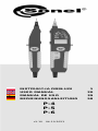 1
1
-
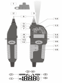 2
2
-
 3
3
-
 4
4
-
 5
5
-
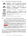 6
6
-
 7
7
-
 8
8
-
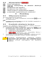 9
9
-
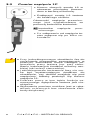 10
10
-
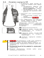 11
11
-
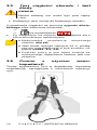 12
12
-
 13
13
-
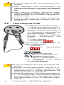 14
14
-
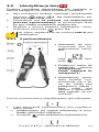 15
15
-
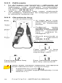 16
16
-
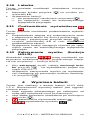 17
17
-
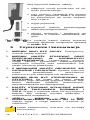 18
18
-
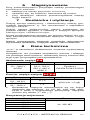 19
19
-
 20
20
-
 21
21
-
 22
22
-
 23
23
-
 24
24
-
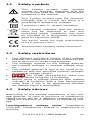 25
25
-
 26
26
-
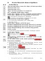 27
27
-
 28
28
-
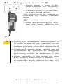 29
29
-
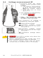 30
30
-
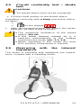 31
31
-
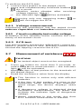 32
32
-
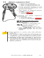 33
33
-
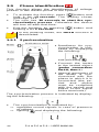 34
34
-
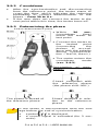 35
35
-
 36
36
-
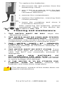 37
37
-
 38
38
-
 39
39
-
 40
40
-
 41
41
-
 42
42
-
 43
43
-
 44
44
-
 45
45
-
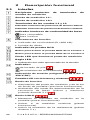 46
46
-
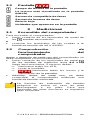 47
47
-
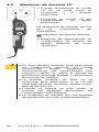 48
48
-
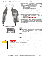 49
49
-
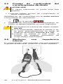 50
50
-
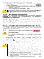 51
51
-
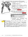 52
52
-
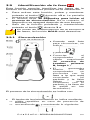 53
53
-
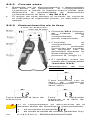 54
54
-
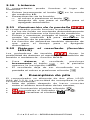 55
55
-
 56
56
-
 57
57
-
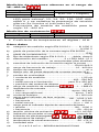 58
58
-
 59
59
-
 60
60
-
 61
61
-
 62
62
-
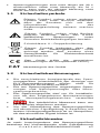 63
63
-
 64
64
-
 65
65
-
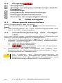 66
66
-
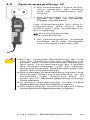 67
67
-
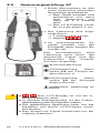 68
68
-
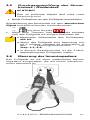 69
69
-
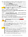 70
70
-
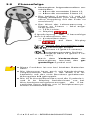 71
71
-
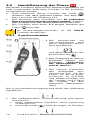 72
72
-
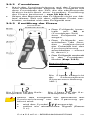 73
73
-
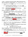 74
74
-
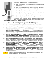 75
75
-
 76
76
-
 77
77
-
 78
78
-
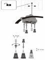 79
79
-
 80
80


Sonel P-4 Manual de usuario
- Categoría
- Medición
- Tipo
- Manual de usuario
en otros idiomas
- English: Sonel P-4 User manual
- Deutsch: Sonel P-4 Benutzerhandbuch
- polski: Sonel P-4 Instrukcja obsługi